Embed Size (px)
Citation preview

SIMATIC 505
High Speed Counterand Encoder Module
User Manual
Order Number: PPX:505–8113–2Manual Assembly Number: 2586546–0019Second Edition

01/21/92
Copyright 1992 by Siemens Industrial Automation, Inc. All Rights Reserved — Printed in USA
Reproduction, transmission or use of this document orcontents is not permitted without express consent ofSiemens Industrial Automation, Inc. All rights, including rightscreated by patent grant or registration of a utility model ordesign, are reserved.
Since Siemens Industrial Automation, Inc. does not possessfull access to data concerning all of the uses and applicationsof customer’s products, we do not assume responsibility eitherfor customer product design or for any infringements of patentsor rights of others which may result from our assistance.
Technical data is subject to change.
We check the contents of every manual for accuracy at thetime it is approved for printing; however, there may beundetected errors. Any errors found will be corrected insubsequent editions. Any suggestions for improvement arewelcomed.
�
Contents iii
Contents
Chapter 1 Overview1.1 Features 1-2. . . . . . . . . . . . . . . . . . . . . . . . . . . . . . . . . . . . . . . . . . . . . . . . . . . . . . . . . .
1.2 Inputs 1–4. . . . . . . . . . . . . . . . . . . . . . . . . . . . . . . . . . . . . . . . . . . . . . . . . . . . . . . . . . . .
1.3 Outputs 1–5. . . . . . . . . . . . . . . . . . . . . . . . . . . . . . . . . . . . . . . . . . . . . . . . . . . . . . . . . . .
1.4 LED Indicators 1–6. . . . . . . . . . . . . . . . . . . . . . . . . . . . . . . . . . . . . . . . . . . . . . . . . . . . .
1.5 Counting Modes 1–7. . . . . . . . . . . . . . . . . . . . . . . . . . . . . . . . . . . . . . . . . . . . . . . . . . 1.5.1 Pulse-Counter Mode 1–7. . . . . . . . . . . . . . . . . . . . . . . . . . . . . . . . . . . . . . . . . . . . . . . . . . 1.5.2 Quadrature Mode 1–8. . . . . . . . . . . . . . . . . . . . . . . . . . . . . . . . . . . . . . . . . . . . . . . . . . . . 1.5.3 1X Quadrature 1-8. . . . . . . . . . . . . . . . . . . . . . . . . . . . . . . . . . . . . . . . . . . . . . . . . . . . . . . 1.5.4 2X Quadrature 1-9. . . . . . . . . . . . . . . . . . . . . . . . . . . . . . . . . . . . . . . . . . . . . . . . . . . . . . . 1.5.5 4X Quadrature 1-10. . . . . . . . . . . . . . . . . . . . . . . . . . . . . . . . . . . . . . . . . . . . . . . . . . . . . . .
Chapter 2 Installation2.1 Before Installing the Module 2–2. . . . . . . . . . . . . . . . . . . . . . . . . . . . . . . . . . . . . . .
2.1.1 Visual Inspection 2-2. . . . . . . . . . . . . . . . . . . . . . . . . . . . . . . . . . . . . . . . . . . . . . . . . . . . . . 2.1.2 Additional References 2-2. . . . . . . . . . . . . . . . . . . . . . . . . . . . . . . . . . . . . . . . . . . . . . . . 2.1.3 Handling the Module 2-2. . . . . . . . . . . . . . . . . . . . . . . . . . . . . . . . . . . . . . . . . . . . . . . . . 2.1.4 General Wiring Considerations 2-3. . . . . . . . . . . . . . . . . . . . . . . . . . . . . . . . . . . . . . . . 2.1.5 Hierarchy of Installation 2-4. . . . . . . . . . . . . . . . . . . . . . . . . . . . . . . . . . . . . . . . . . . . . . .
2.2 Selecting Counter Operation 2-5. . . . . . . . . . . . . . . . . . . . . . . . . . . . . . . . . . . . . . 2.2.1 Selecting Counter Mode 2-5. . . . . . . . . . . . . . . . . . . . . . . . . . . . . . . . . . . . . . . . . . . . . . 2.2.2 Selecting the Reset Filter 2-6. . . . . . . . . . . . . . . . . . . . . . . . . . . . . . . . . . . . . . . . . . . . . .
2.3 Inserting the Module in the I/O Base 2-7. . . . . . . . . . . . . . . . . . . . . . . . . . . . . . .
2.4 Wiring the Module 2-8. . . . . . . . . . . . . . . . . . . . . . . . . . . . . . . . . . . . . . . . . . . . . . . . . 2.4.1 Wiring the Terminal Block 2-8. . . . . . . . . . . . . . . . . . . . . . . . . . . . . . . . . . . . . . . . . . . . . . 2.4.2 Powering Up the Module 2-8. . . . . . . . . . . . . . . . . . . . . . . . . . . . . . . . . . . . . . . . . . . . . .
2.5 Logging the Module into the Controller 2-10. . . . . . . . . . . . . . . . . . . . . . . . . . . . . 2.5.1 Updating the I/O Configuration Definition 2-10. . . . . . . . . . . . . . . . . . . . . . . . . . . . . . 2.5.2 Selecting the I/O Configuration 2-10. . . . . . . . . . . . . . . . . . . . . . . . . . . . . . . . . . . . . . . . 2.5.3 Viewing I/O Configuration Chart 2-11. . . . . . . . . . . . . . . . . . . . . . . . . . . . . . . . . . . . . .
Chapter 3 Programming3.1 Controller Input Words 3-2. . . . . . . . . . . . . . . . . . . . . . . . . . . . . . . . . . . . . . . . . . . .
3.1.1 WX1 (Status Word) 3-2. . . . . . . . . . . . . . . . . . . . . . . . . . . . . . . . . . . . . . . . . . . . . . . . . . . . 3.1.2 WX2 and WX3 (Channel Count) 3-3. . . . . . . . . . . . . . . . . . . . . . . . . . . . . . . . . . . . . . . 3.1.3 WY4 (Setup Word) 3-3. . . . . . . . . . . . . . . . . . . . . . . . . . . . . . . . . . . . . . . . . . . . . . . . . . . . 3.1.4 WY5 – WY8 (Preset Words) 3-4. . . . . . . . . . . . . . . . . . . . . . . . . . . . . . . . . . . . . . . . . . . . . 3.1.5 I/O Update Consideration 3-4. . . . . . . . . . . . . . . . . . . . . . . . . . . . . . . . . . . . . . . . . . . . .
iv Contents
Chapter 4 Troubleshooting4.1 Checking the Operation of the Module 4-2. . . . . . . . . . . . . . . . . . . . . . . . . . . . .
Chapter 5 Applications5.1 Sprayer Example 5-2. . . . . . . . . . . . . . . . . . . . . . . . . . . . . . . . . . . . . . . . . . . . . . . . . .
5.1.1 Description 5-2. . . . . . . . . . . . . . . . . . . . . . . . . . . . . . . . . . . . . . . . . . . . . . . . . . . . . . . . . . . 5.1.2 Solution 5-3. . . . . . . . . . . . . . . . . . . . . . . . . . . . . . . . . . . . . . . . . . . . . . . . . . . . . . . . . . . . . .
5.2 Flow Rate Example 5-5. . . . . . . . . . . . . . . . . . . . . . . . . . . . . . . . . . . . . . . . . . . . . . . . 5.2.1 Description 5-5. . . . . . . . . . . . . . . . . . . . . . . . . . . . . . . . . . . . . . . . . . . . . . . . . . . . . . . . . . . 5.2.2 Solution 5-5. . . . . . . . . . . . . . . . . . . . . . . . . . . . . . . . . . . . . . . . . . . . . . . . . . . . . . . . . . . . . .
5.3 Tank Filling Example 5-6. . . . . . . . . . . . . . . . . . . . . . . . . . . . . . . . . . . . . . . . . . . . . . . 5.3.1 Description 5-6. . . . . . . . . . . . . . . . . . . . . . . . . . . . . . . . . . . . . . . . . . . . . . . . . . . . . . . . . . . 5.3.2 Solution 5-6. . . . . . . . . . . . . . . . . . . . . . . . . . . . . . . . . . . . . . . . . . . . . . . . . . . . . . . . . . . . . .
Appendix A Terminal Block WorksheetA.1 Terminal Block Worksheet A-1. . . . . . . . . . . . . . . . . . . . . . . . . . . . . . . . . . . . . . . . .
Appendix B SpecificationsB.1 Environmental Specifications B-2. . . . . . . . . . . . . . . . . . . . . . . . . . . . . . . . . . . . . .
B.2 Electrical Specifications B-3. . . . . . . . . . . . . . . . . . . . . . . . . . . . . . . . . . . . . . . . . . .
B.3 Additional Compliances B-6. . . . . . . . . . . . . . . . . . . . . . . . . . . . . . . . . . . . . . . . . . .
�
Contents v
List of Figures
1-1 High Speed Counter Module 1-3. . . . . . . . . . . . . . . . . . . . . . . . . . . . . . . . . . . . . . 1-2 Output 1-5. . . . . . . . . . . . . . . . . . . . . . . . . . . . . . . . . . . . . . . . . . . . . . . . . . . . . . . . . . . 1-3 High Speed Counter LEDs 1-6. . . . . . . . . . . . . . . . . . . . . . . . . . . . . . . . . . . . . . . . . 1-4 Pulse Counter Mode 0 1-7. . . . . . . . . . . . . . . . . . . . . . . . . . . . . . . . . . . . . . . . . . . . . 1-5 1X Quadrature Mode 1-8. . . . . . . . . . . . . . . . . . . . . . . . . . . . . . . . . . . . . . . . . . . . . 1-6 2X Quadrature Mode 1-9. . . . . . . . . . . . . . . . . . . . . . . . . . . . . . . . . . . . . . . . . . . . . 1-7 4X Quadrature Mode 1-10. . . . . . . . . . . . . . . . . . . . . . . . . . . . . . . . . . . . . . . . . . . . .
2-1 Hierarchy of Installation 2-4. . . . . . . . . . . . . . . . . . . . . . . . . . . . . . . . . . . . . . . . . . . 2-2 Jumper Settings 2-5. . . . . . . . . . . . . . . . . . . . . . . . . . . . . . . . . . . . . . . . . . . . . . . . . . . 2-3 Inserting the Module into the I/O Base 2-7. . . . . . . . . . . . . . . . . . . . . . . . . . . . . . 2-4 Wiring Guidelines 2-8. . . . . . . . . . . . . . . . . . . . . . . . . . . . . . . . . . . . . . . . . . . . . . . . . 2-5 Sample Terminal Block Wiring Diagram 2-9. . . . . . . . . . . . . . . . . . . . . . . . . . . . . 2-6 Sample I/O Definition Chart 2-10. . . . . . . . . . . . . . . . . . . . . . . . . . . . . . . . . . . . . . . 2-7 I/O Configuration Chart 2-11. . . . . . . . . . . . . . . . . . . . . . . . . . . . . . . . . . . . . . . . . . .
3-1 Status Word Format 3-2. . . . . . . . . . . . . . . . . . . . . . . . . . . . . . . . . . . . . . . . . . . . . . . 3-2 Setup Word Format 3-3. . . . . . . . . . . . . . . . . . . . . . . . . . . . . . . . . . . . . . . . . . . . . . .
5-1 Sprayer Application 5-2. . . . . . . . . . . . . . . . . . . . . . . . . . . . . . . . . . . . . . . . . . . . . . . 5-2 HSC Connections 5-3. . . . . . . . . . . . . . . . . . . . . . . . . . . . . . . . . . . . . . . . . . . . . . . . . 5-3 Waveform Pattern 5-3. . . . . . . . . . . . . . . . . . . . . . . . . . . . . . . . . . . . . . . . . . . . . . . . 5-4 Ladder Logic for Sprayer Example 5-4. . . . . . . . . . . . . . . . . . . . . . . . . . . . . . . . . 5-5 Ladder Logic for Flow Rate Example 5-5. . . . . . . . . . . . . . . . . . . . . . . . . . . . . . . 5-6 Tank Filling Application 5-6. . . . . . . . . . . . . . . . . . . . . . . . . . . . . . . . . . . . . . . . . . . . 5-7 Ladder Logic for Tank Filling Example 5-7. . . . . . . . . . . . . . . . . . . . . . . . . . . . . . .

vi Contents
List of Tables
1-1 Determining Count in Pulse Counter Mode 1-7. . . . . . . . . . . . . . . . . . . . . . . . .
B-1 Environmental Specifications B-2. . . . . . . . . . . . . . . . . . . . . . . . . . . . . . . . . . . . . . B-2 Electrical Specifications B-3. . . . . . . . . . . . . . . . . . . . . . . . . . . . . . . . . . . . . . . . . . .
�
Overview 1-1Series 505 High Speed Counter and Encoder Module User’s Manual
Chapter 1
Overview
1.1 Features 1-2. . . . . . . . . . . . . . . . . . . . . . . . . . . . . . . . . . . . . . . . . . . . . . . . . . . . . . . . . .
1.2 Inputs 1-4. . . . . . . . . . . . . . . . . . . . . . . . . . . . . . . . . . . . . . . . . . . . . . . . . . . . . . . . . . . .
1.3 Outputs 1-5. . . . . . . . . . . . . . . . . . . . . . . . . . . . . . . . . . . . . . . . . . . . . . . . . . . . . . . . . . .
1.4 LED Indicators 1-6. . . . . . . . . . . . . . . . . . . . . . . . . . . . . . . . . . . . . . . . . . . . . . . . . . . . .
1.5 Counting Modes 1-7. . . . . . . . . . . . . . . . . . . . . . . . . . . . . . . . . . . . . . . . . . . . . . . . . . 1.5.1 Pulse-Counter Mode 1-7. . . . . . . . . . . . . . . . . . . . . . . . . . . . . . . . . . . . . . . . 1.5.2 Quadrature Mode Overview 1-8. . . . . . . . . . . . . . . . . . . . . . . . . . . . . . . . 1.5.3 1X Quadrature 1-8. . . . . . . . . . . . . . . . . . . . . . . . . . . . . . . . . . . . . . . . . . . . . . 1.5.4 2X Quadrature 1-9. . . . . . . . . . . . . . . . . . . . . . . . . . . . . . . . . . . . . . . . . . . . . . 1.5.5 4X Quadrature 1-10. . . . . . . . . . . . . . . . . . . . . . . . . . . . . . . . . . . . . . . . . . . . . .
��������1-2 Series 505 High Speed Counter and Encoder Module User’s Manual
1.1 Features
The Series 505 High Speed Counter (HSC) module (PPX:505-7002)provides two independent high-speed counter channels.
Each channel has the following features.
� Four counter modes:
� Pulse counter
� Quadrature counter modes: 1X, 2X, 4X
� A 10 kHz count rate with a minimum pulse width of 25 �s.
� Four inputs:
� two count inputs
� reset
� inhibit
� Two field outputs, each controlled by a separate programmable preset.
� LED indicators display the status of the A and B count inputs, and ofY1 and Y2 outputs.
All inputs may be sinking or sourcing (with external 24 VDC powersupply).
The HSC module operates asynchronously from the controller scan. Youcan program the controller to monitor the HSC and/or to provide high-levelcontrol of the HSC’s operation. To support these functions, the HSCprovides reset, inhibit, output and counter status to the controller andaccepts reset and inhibit commands, and preset values from the controller.
! ������� The HSC module controls its four outputs. If the controller switches from the Runmode to the Program mode, the HSC continues to function as programmed, andoutputs may be activated by the HSC. This means that if you switch the controllerto Program mode, any devices controlled by the four outputs of the HSC willcontinue to operate as programmed.
�
Overview 1-3Series 505 High Speed Counter and Encoder Module User’s Manual
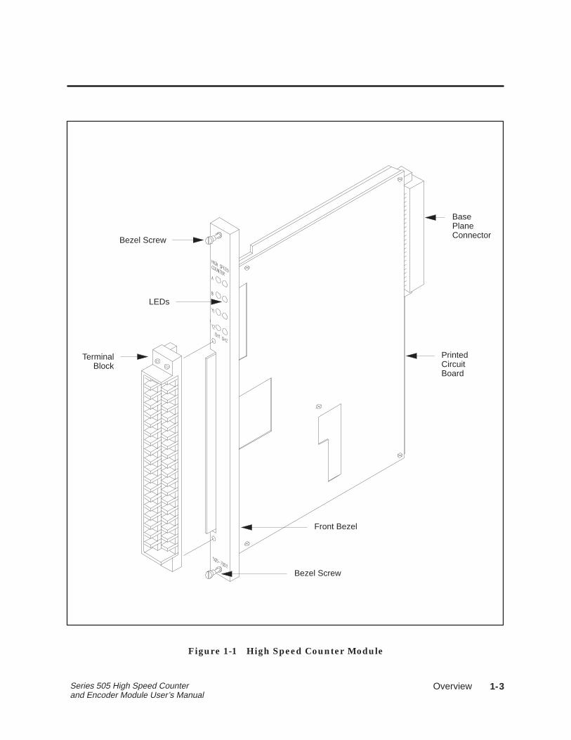
BasePlaneConnector
PrintedCircuitBoard
Front Bezel
Bezel Screw
LEDs
TerminalBlock
Bezel Screw
Figure 1-1 High Speed Counter Module
��������1-4 Series 505 High Speed Counter and Encoder Module User’s Manual
1.2 Inputs
The HSC module has two independent channels. Each channel has fourinputs.
� Reset
� Inhibit
� Two counter inputs
Each input may be used as either sinking or sourcing (with external 5–24VDC power supply). The input signals are connected to the field wiringterminal block on the front bezel.
������� �������Each channel has two counter inputs — Input A andInput B.
������Current flow through the reset input sets the channel’s counter tozero. The counter will be held at zero until the reset input becomesinactive.
��� ��Current flow through the inhibit input inhibits the channel fromcounting. The counter holds at the last value and does not change until theinhibit input becomes inactive.
���� When in the pulse counter mode, if the A or B input is in adifferent state at the beginning and end of an inhibit signal, the count willchange according to the normal counting logic. If both A and B inputs arein different states, the change may be as much as two counts.
���� There are also software reset and inhibit functions. See Section 3.
�
Overview 1-5Series 505 High Speed Counter and Encoder Module User’s Manual
1.3 Outputs
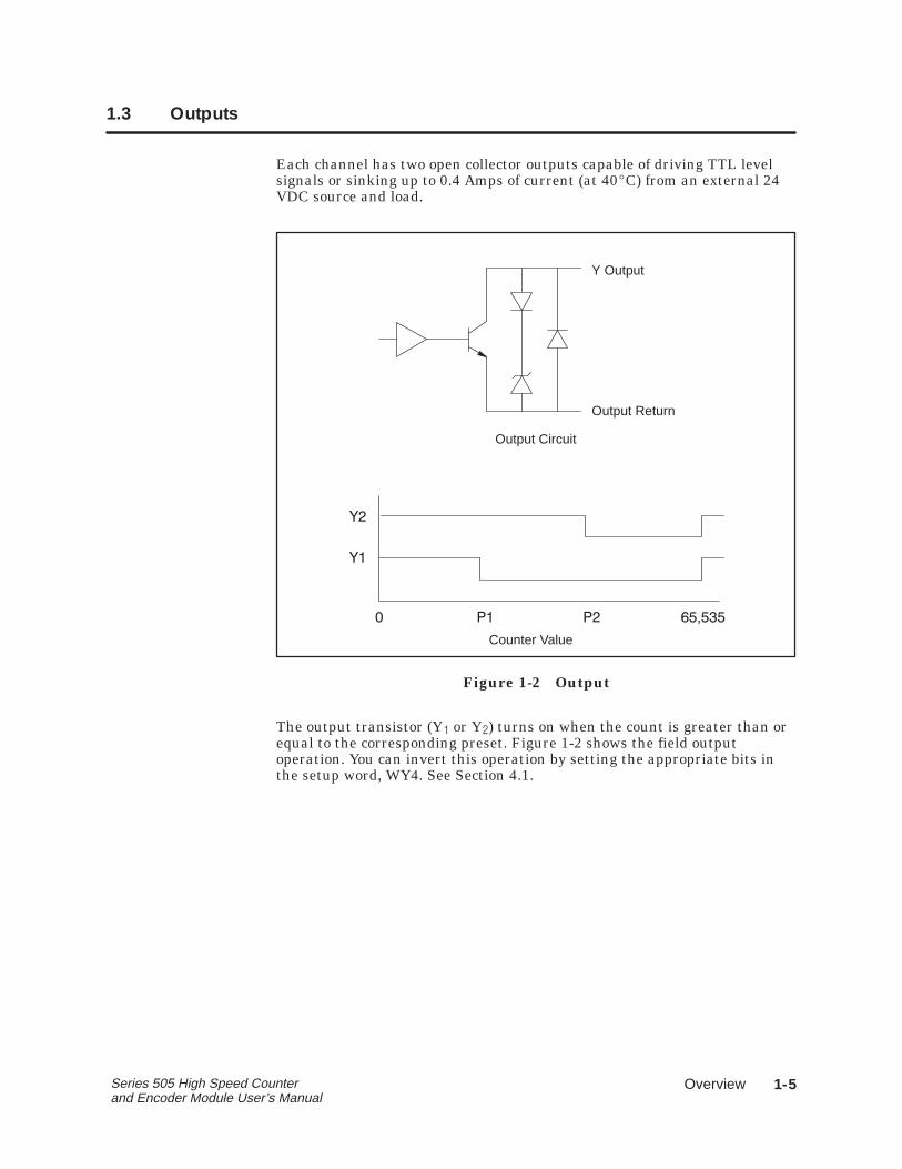
Each channel has two open collector outputs capable of driving TTL levelsignals or sinking up to 0.4 Amps of current (at 40�C) from an external 24VDC source and load.
Y Output
Output Return
Output Circuit
� �� �� ������
�
�
Counter Value
Figure 1-2 Output
The output transistor (Y� or Y�) turns on when the count is greater than orequal to the corresponding preset. Figure 1-2 shows the field outputoperation. You can invert this operation by setting the appropriate bits inthe setup word, WY4. See Section 4.1.
��������1-6 Series 505 High Speed Counter and Encoder Module User’s Manual
1.4 LED Indicators
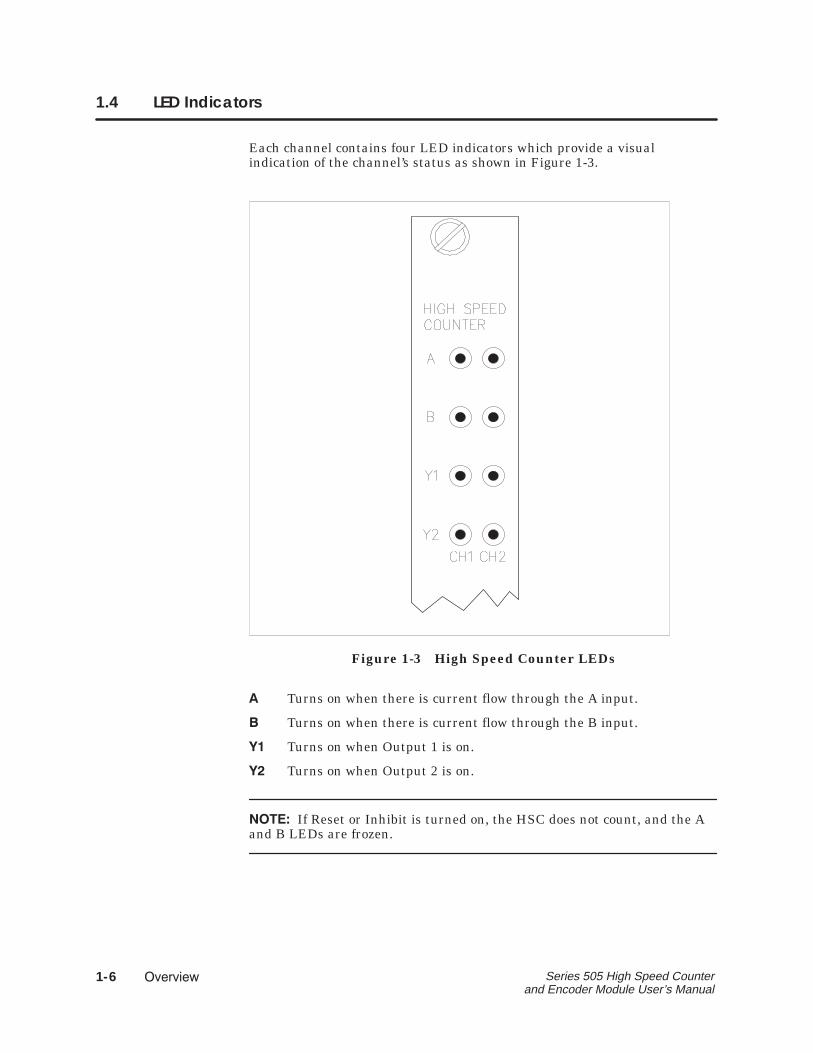
Each channel contains four LED indicators which provide a visualindication of the channel’s status as shown in Figure 1-3.
Figure 1-3 High Speed Counter LEDs
� Turns on when there is current flow through the A input.
� Turns on when there is current flow through the B input.
� Turns on when Output 1 is on.
� Turns on when Output 2 is on.
�����If Reset or Inhibit is turned on, the HSC does not count, and the Aand B LEDs are frozen.
�
Overview 1-7Series 505 High Speed Counter and Encoder Module User’s Manual
1.5 Counting Modes
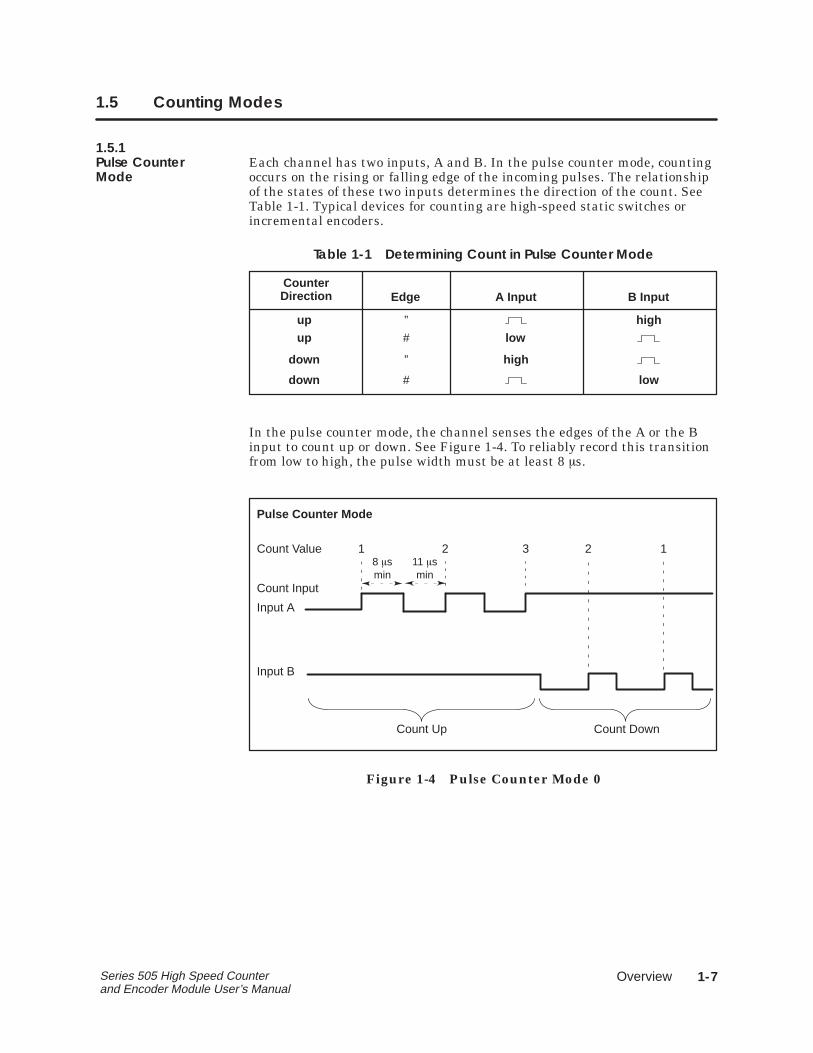
1.5.1Pulse Counter Each channel has two inputs, A and B. In the pulse counter mode, countingMode occurs on the rising or falling edge of the incoming pulses. The relationship
of the states of these two inputs determines the direction of the count. SeeTable 1-1. Typical devices for counting are high-speed static switches orincremental encoders.
Table 1-1 Determining Count in Pulse Counter Mode
CounterDirection Edge A Input B Input
up
up
down
down
”
”
#
#
low
high
high
low
In the pulse counter mode, the channel senses the edges of the A or the Binput to count up or down. See Figure 1-4. To reliably record this transitionfrom low to high, the pulse width must be at least 8 �s.
Count Value
Count Input
2 3 2 18 �smin
Input A
Input B
Count Up Count Down
Pulse Counter Mode
11 �smin
1
Figure 1-4 Pulse Counter Mode 0
��������1-8 Series 505 High Speed Counter and Encoder Module User’s Manual
Counting Modes (continued)
1.5.2Quadrature Mode For quadrature mode, each channel counts according to rising and/or�������� falling edges. Typical devices for quadrature inputs are optical encoders.
Different quadrature modes are selected based on the resolution requiredby the application and the encoder used.
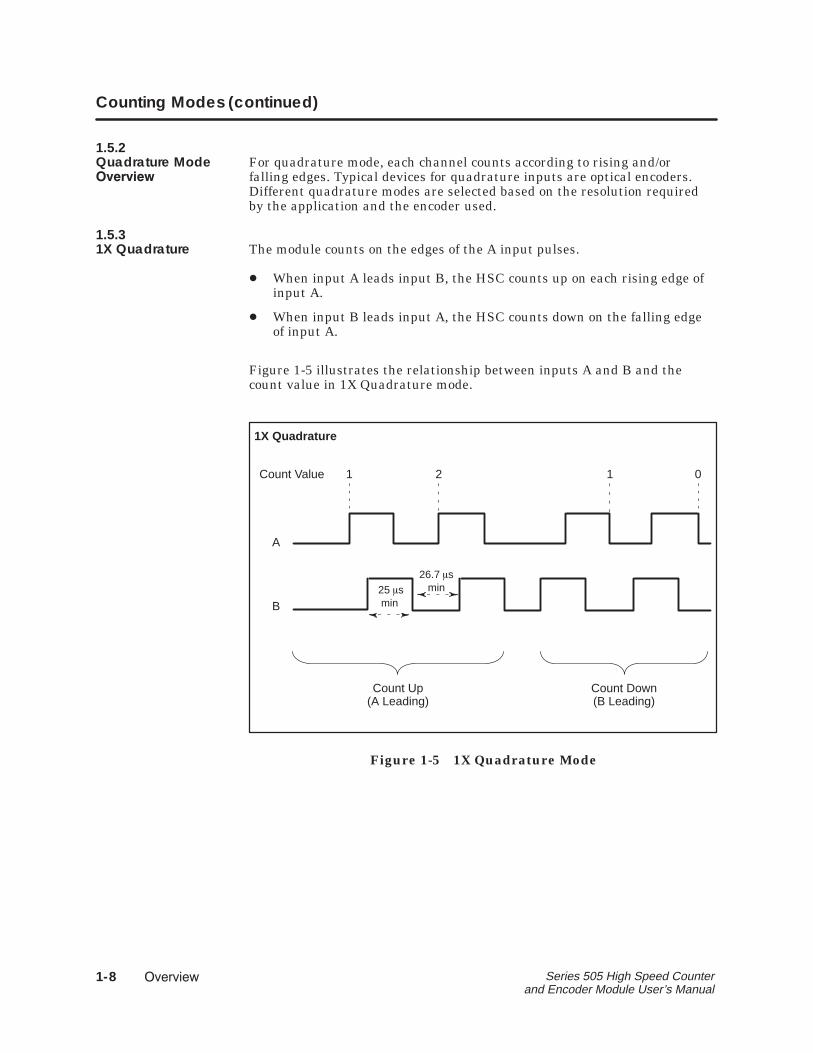
1.5.31X Quadrature The module counts on the edges of the A input pulses.
� When input A leads input B, the HSC counts up on each rising edge ofinput A.
� When input B leads input A, the HSC counts down on the falling edgeof input A.
Figure 1-5 illustrates the relationship between inputs A and B and thecount value in 1X Quadrature mode.
Count Value
1X Quadrature
1 2 1 0
A
B25 �s min
Count Up(A Leading)
Count Down(B Leading)
26.7 �smin
Figure 1-5 1X Quadrature Mode

�
Overview 1-9Series 505 High Speed Counter and Encoder Module User’s Manual
1.5.42X Quadrature If input A leads input B, the module counts up on both the rising and
falling edges of input A. If input B leads input A, the module counts downon the rising and falling edges of input A.
Figure 1-6 illustrates the relationship between inputs A and B and thecount value in the 2X quadrature mode.
2X Quadrature
1 2 3 4 3 2 1 0
A
B
25 �s min
Counts Up(A Leading)
Counts Down(B Leading)
Count Value
26.7 �smin
Figure 1-6 2X Quadrature Mode
��������1-10 Series 505 High Speed Counter and Encoder Module User’s Manual
Counting Modes (continued)
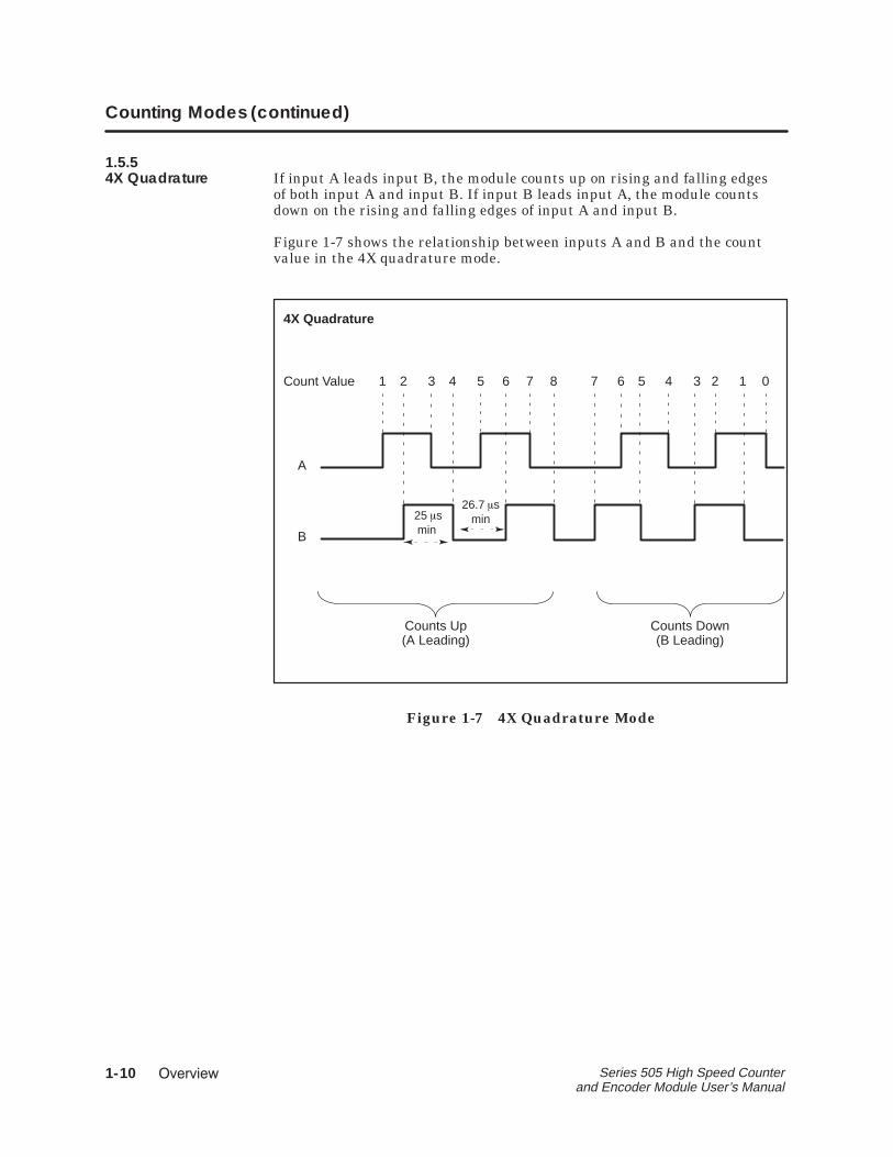
1.5.54X Quadrature If input A leads input B, the module counts up on rising and falling edges
of both input A and input B. If input B leads input A, the module countsdown on the rising and falling edges of input A and input B.
Figure 1-7 shows the relationship between inputs A and B and the countvalue in the 4X quadrature mode.
4X Quadrature
1 2 3 4 5 6 7 8 7 6 5 4 3 2 1 0
A
B
25 �s min
Counts Up(A Leading)
Count Value
Counts Down(B Leading)
26.7 �smin
Figure 1-7 4X Quadrature Mode
�
Installation 2-1Series 505 High Speed Counter and Encoder Module User’s Manual
Chapter 2
Installation
2.1 Before Installing the Module 2–2. . . . . . . . . . . . . . . . . . . . . . . . . . . . . . . . . . . . . . . 2.1.1 Visual Inspection 2-2. . . . . . . . . . . . . . . . . . . . . . . . . . . . . . . . . . . . . . . . . . . . 2.1.2 Additional References 2-2. . . . . . . . . . . . . . . . . . . . . . . . . . . . . . . . . . . . . . . 2.1.3 Handling the Module 2-2. . . . . . . . . . . . . . . . . . . . . . . . . . . . . . . . . . . . . . . . 2.1.4 General Wiring Considerations 2-3. . . . . . . . . . . . . . . . . . . . . . . . . . . . . . . 2.1.5 Hierarchy of Installation 2-4. . . . . . . . . . . . . . . . . . . . . . . . . . . . . . . . . . . . .
2.2 Selecting Counter Operation 2-5. . . . . . . . . . . . . . . . . . . . . . . . . . . . . . . . . . . . . . 2.2.1 Selecting Counter Mode 2-5. . . . . . . . . . . . . . . . . . . . . . . . . . . . . . . . . . . . 2.2.2 Selecting the Reset Filter 2-6. . . . . . . . . . . . . . . . . . . . . . . . . . . . . . . . . . . . .
2.3 Inserting the Module in the I/O Base 2-7. . . . . . . . . . . . . . . . . . . . . . . . . . . . . . .
2.4 Wiring the Module 2-8. . . . . . . . . . . . . . . . . . . . . . . . . . . . . . . . . . . . . . . . . . . . . . . . . 2.4.1 Wiring the Terminal Block 2-8. . . . . . . . . . . . . . . . . . . . . . . . . . . . . . . . . . . . 2.4.2 Powering Up the Module 2-8. . . . . . . . . . . . . . . . . . . . . . . . . . . . . . . . . . . .
2.5 Logging the Module into the Controller 2-10. . . . . . . . . . . . . . . . . . . . . . . . . . . . . 2.5.1 Updating the I/O Configuration Definition 2-10. . . . . . . . . . . . . . . . . . . . 2.5.2 Selecting the I/O Configuration 2-10. . . . . . . . . . . . . . . . . . . . . . . . . . . . . . 2.5.3 Viewing I/O Configuration Chart 2-11. . . . . . . . . . . . . . . . . . . . . . . . . . . . .
2-2 Installation Series 505 High Speed Counter and Encoder Module User’s Manual
2.1 Before Installing the Module
2.1.1Visual Inspection If there is any visible damage to the module, contact your Siemens
Industrial Automation, Inc. distributor for replacement.
2.1.2Additional Refer to the manuals listed below for instructions on installing,References programming, and troubleshooting your Series 505E controller.
� SIMATIC� TI545 System Manual (PPX:545–8101)
� SIMATIC� TI525 /TI535 Hardware and Installation Manual(PPX:505–8103)
� SIMATIC� TI505 Programming Reference Manual (PPX:505–8104)
2.1.3Handling the Many integrated circuit (IC) devices are susceptible to damage by theModule discharge of static electricity. Follow the suggestions listed below to reduce
the probability of damage to these devices when you are handling acontroller, a base controller, or any of the I/O modules.
Both the module and the person handling the module should be at thesame ground potential. To accomplish this, ensure the following.
� The module is transported in an anti-static container or antistaticmaterial.
� The work area has a conductive pad with a lead connecting it to acommon ground.
� You are grounded by making contact with the conductive pad and/or bywearing a grounded wrist strap.
�
Installation 2-3Series 505 High Speed Counter and Encoder Module User’s Manual
2.1.4General Wiring The count, inhibit, and unfiltered reset inputs are high-speed inputs whichConsiderations may respond to noise present on the lines. To avoid problems, follow these
guidelines when installing the HSC module.
� Use the shortest possible wires.
� Avoid placing signal wires parallel to high-energy wires. If the twomust meet, cross them at right angles.
� Avoid bending the wire into sharp angles.
� Use wireways for wire routing.
� When using shielded wires, ground them only at the source end forbetter noise immunity.
� Place wires so that they don’t interfere with existing wiring.
� Label the wires.
In some installations when both the HSC and TI505-49XX series of relaymodules are used, false counts may be induced when switching highvoltage in the relay module, (voltage > 40 Vrms). This is the result ofinternal arcing of the relay contacts.
If you encounter this problem, place a snubber consisting of a 47 ohm 1/4watt resistor and a 0.022 �Fd capacitor across the relay contact terminalson the terminal block. Snubbers were not included in the relay modules inorder to meet the need for lower current leakage in many applications.
����: Snubber components must be UL� component recognizedand/or CSA Certified for use across the rated voltage being switchedby the relay module.
2-4 Installation Series 505 High Speed Counter and Encoder Module User’s Manual
Before Installing the Module (continued)
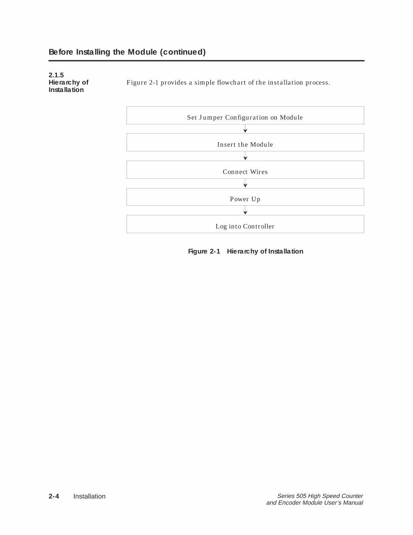
2.1.5Hierarchy of Figure 2-1 provides a simple flowchart of the installation process.Installation
Insert the Module
Connect Wires
Set Jumper Configuration on Module
Power Up
Log into Controller
Figure 2-1 Hierarchy of Installation
�
Installation 2-5Series 505 High Speed Counter and Encoder Module User’s Manual
2.2 Selecting Counter Operation
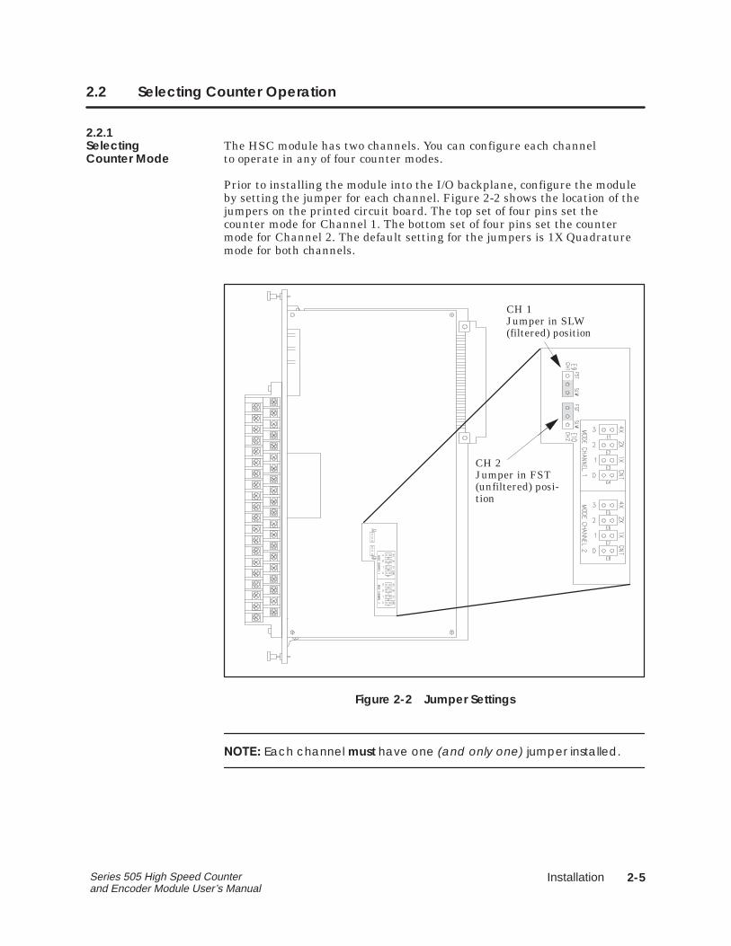
2.2.1Selecting The HSC module has two channels. You can configure each channelCounter Mode to operate in any of four counter modes.
Prior to installing the module into the I/O backplane, configure the moduleby setting the jumper for each channel. Figure 2-2 shows the location of thejumpers on the printed circuit board. The top set of four pins set thecounter mode for Channel 1. The bottom set of four pins set the countermode for Channel 2. The default setting for the jumpers is 1X Quadraturemode for both channels.
CH 1Jumper in SLW(filtered) position
CH 2Jumper in FST(unfiltered) posi-tion
Figure 2-2 Jumper Settings
����� Each channel must have one (and only one) jumper installed.
2-6 Installation Series 505 High Speed Counter and Encoder Module User’s Manual
Selecting Counter Operation (continued)
2.2.2Selecting the Some applications require faster response on the reset input line thanReset Filter the standard 3.75-ms filter allows. For faster response, select the optional
0.95-ms filter. (The 0.9-ms filter is more sensitive to noisy signals, as notedin the Environmental Specifications in Appendix B.)
The reset filter may be selected independently for each input channel byplacing the jumper in the ��� (fast) or ��� (slow) position as shown inFigure 2-2.
�
Installation 2-7Series 505 High Speed Counter and Encoder Module User’s Manual
2.3 Inserting the Module in the I/O Base
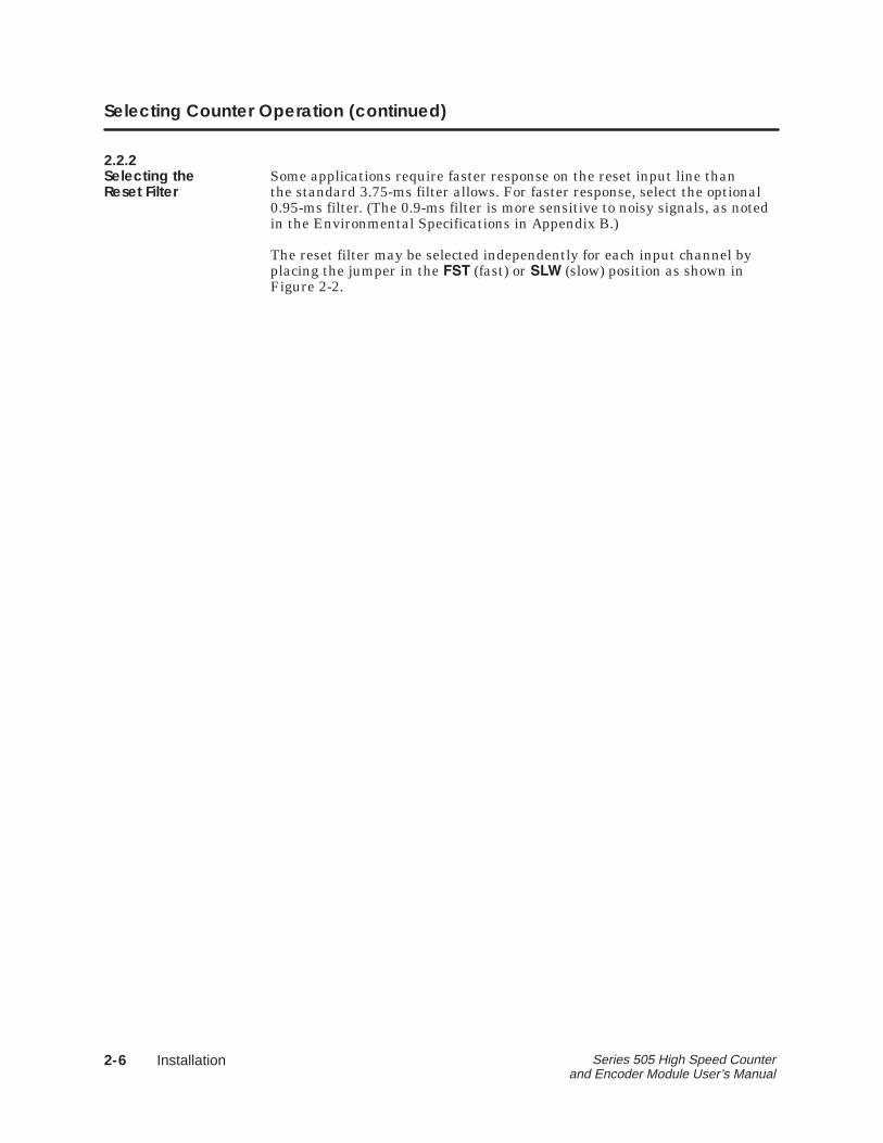
The HSC is a single-wide module. Insert it into any available slot on anySeries 505 I/O base. Do not touch the printed circuit board while insertingthe module. This could cause electrostatic damage to the components onthe board. Insert the module as shown in Figure 2-3.
! ������� To minimize potential shock, turn off power to the I/O base and anymodules installed in the base before inserting or removing a module.Failure to do so may result in potential injury to personnel or damage toequipment.
Base PlaneConnectors
��������������������� �� �� ���
Figure 2-3 Inserting the Module into the I/O Base
2-8 Installation Series 505 High Speed Counter and Encoder Module User’s Manual
2.4 Wiring the Module
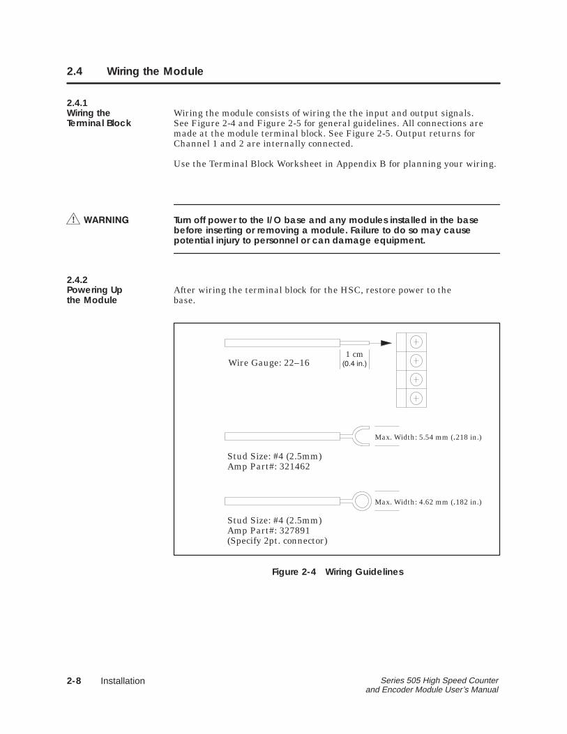
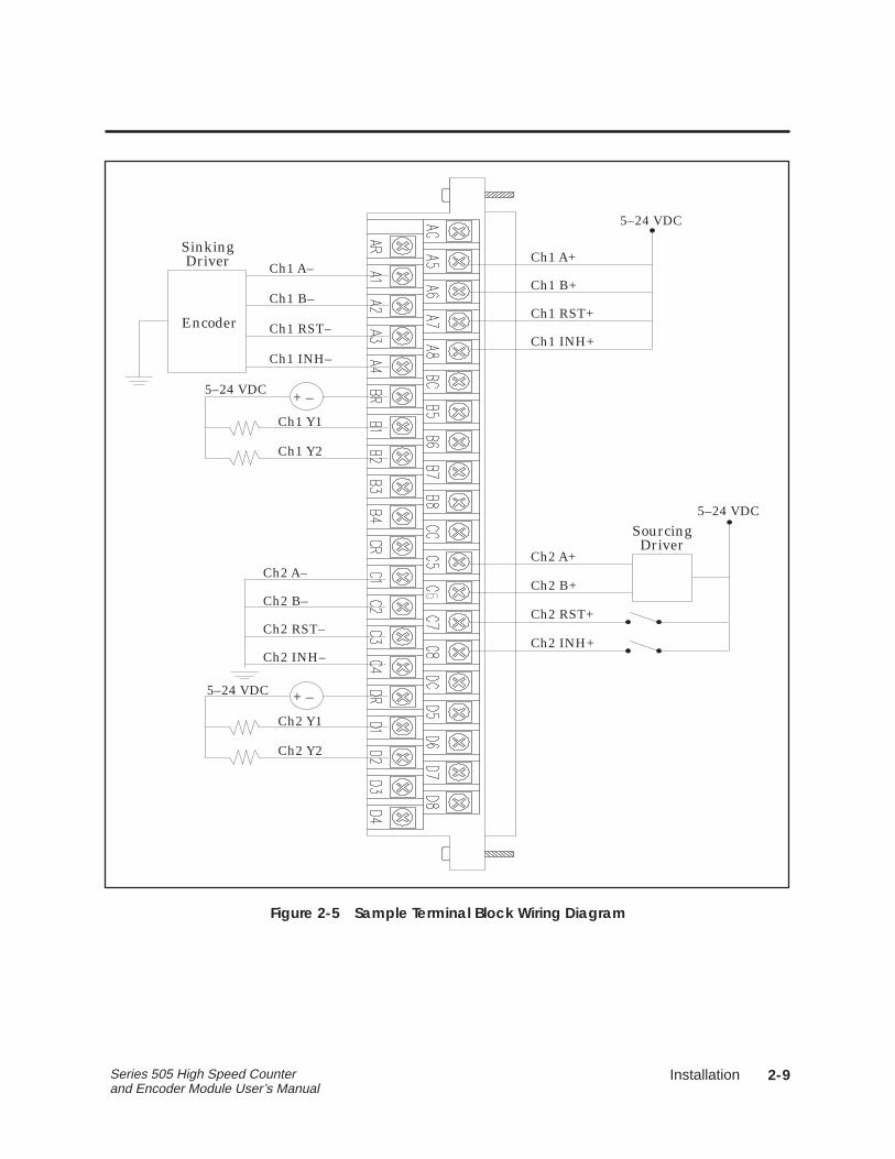
2.4.1Wiring the Wiring the module consists of wiring the the input and output signals.Terminal Block See Figure 2-4 and Figure 2-5 for general guidelines. All connections are
made at the module terminal block. See Figure 2-5. Output returns forChannel 1 and 2 are internally connected.
Use the Terminal Block Worksheet in Appendix B for planning your wiring.
! ������� Turn off power to the I/O base and any modules installed in the basebefore inserting or removing a module. Failure to do so may causepotential injury to personnel or can damage equipment.
2.4.2Powering Up After wiring the terminal block for the HSC, restore power to thethe Module base.
1 cm���� ����Wire Gauge: 22–16
Max. Width: 5.54 mm (.218 in.)
Stud Size: #4 (2.5mm)Amp Part#: 321462
Max. Width: 4.62 mm (.182 in.)
Stud Size: #4 (2.5mm)Amp Part#: 327891(Specify 2pt. connector)
Figure 2-4 Wiring Guidelines
�
Installation 2-9Series 505 High Speed Counter and Encoder Module User’s Manual
Ch1 A+
Ch1 B+
Ch1 RST+
Ch1 INH+
5–24 VDC
Ch2 A+
Ch2 B+
Ch2 RST+
Ch2 INH+
5–24 VDC
SourcingDriver
Ch2 INH–
Ch2 RST–
Ch2 B–
Ch2 A–
Ch2 Y2
Ch2 Y1
+ –
Ch1 Y2
Ch1 Y1
+ –
Sinking
5–24 VDC
Ch1 A–
Ch1 B–
Ch1 RST–
Ch1 INH–
Driver
Encoder
5–24 VDC
Figure 2-5 Sample Terminal Block Wiring Diagram
2-10 Installation Series 505 High Speed Counter and Encoder Module User’s Manual
2.5 Logging the Module into the Controller
2.5.1Updating the I/O After inserting the module into the base, update the I/O configurationConfiguration in the controller. The module does not automatically onfigure itself.Definition A VPU or other programming device must be connected to the controller to
register and verify controller module communication.
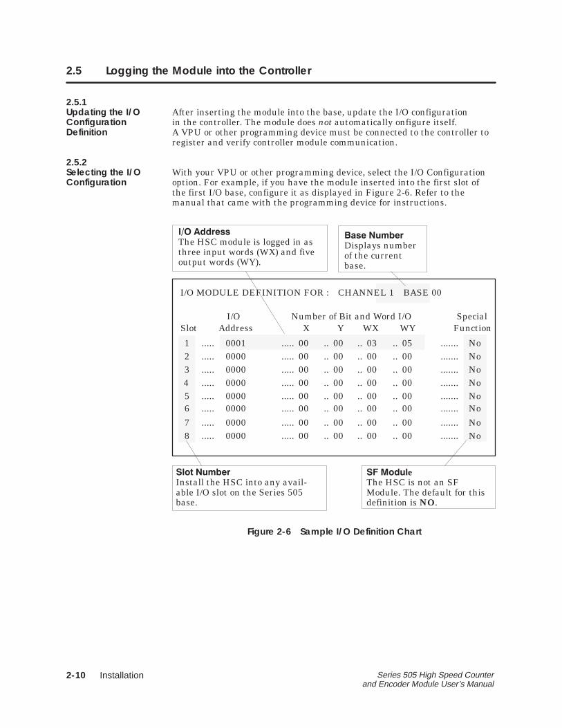
2.5.2Selecting the I/O With your VPU or other programming device, select the I/O ConfigurationConfiguration option. For example, if you have the module inserted into the first slot of
the first I/O base, configure it as displayed in Figure 2-6. Refer to themanual that came with the programming device for instructions.
I/O MODULE DEFINITION FOR : CHANNEL 1 BASE 00
Slot Address X Y WX WY FunctionI/O Number of Bit and Word I/O Special
123456
78
.....
.....
.....
.....
.....
.....
.....
.....
000100000000000000000000
00000000
.....
.....
.....
.....
.....
.....
.....
.....
000000000000
0000
..
..
..
..
..
..
..
..
000000000000
0000
..
..
..
..
..
..
..
..
0000000000
0000
..
..
..
..
..
..
..
..
0000000000
0000
.......
.......
.......
.......
.......
.......
.......
.......
NoNoNoNoNoNo
NoNo
03 05
���� ������ Displays numberof the currentbase.
��� ������ Install the HSC into any avail-able I/O slot on the Series 505base.
�� � ���� The HSC module is logged in asthree input words (WX) and fiveoutput words (WY).
� �� ��e The HSC is not an SFModule. The default for thisdefinition is NO.
Figure 2-6 Sample I/O Definition Chart
�
Installation 2-11Series 505 High Speed Counter and Encoder Module User’s Manual
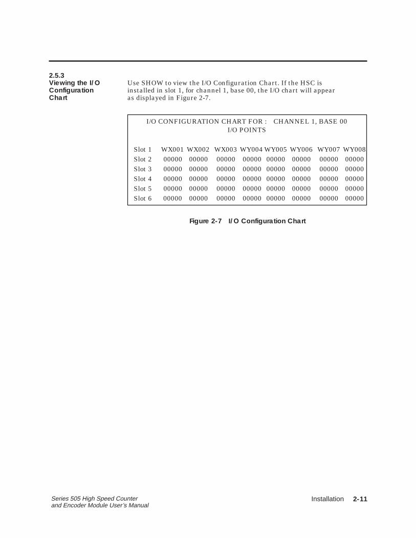
2.5.3Viewing the I/O Use SHOW to view the I/O Configuration Chart. If the HSC isConfiguration installed in slot 1, for channel 1, base 00, the I/O chart will appearChart as displayed in Figure 2-7.
I/O CONFIGURATION CHART FOR : CHANNEL 1, BASE 00
Slot 1
I/O POINTS
Slot 2Slot 3Slot 4Slot 5Slot 6
00000000000000000000
00000000000000000000
00000000000000000000
00000000000000000000
00000000000000000000
00000000000000000000
00000000000000000000
00000000000000000000
00000 00000 00000 00000 00000 00000 00000 00000WX001 WX002 WX003 WY004 WY005 WY006 WY007 WY008
Figure 2-7 I/O Configuration Chart
�
Programming 3-1Series 505 High Speed Counter and Encoder Module User’s Manual
Chapter 3
Programming
3.1 Controller Input Words 3-2. . . . . . . . . . . . . . . . . . . . . . . . . . . . . . . . . . . . . . . . . . . . . . 3.1.1 WX1 (Status Word) 3-2. . . . . . . . . . . . . . . . . . . . . . . . . . . . . . . . . . . . . . . . . . . . . . . . . . . . 3.1.2 WX2 and WX3 (Channel Count) 3-3. . . . . . . . . . . . . . . . . . . . . . . . . . . . . . . . . . . . . . . 3.1.3 WY4 (Setup Word) 3-3. . . . . . . . . . . . . . . . . . . . . . . . . . . . . . . . . . . . . . . . . . . . . . . . . . . . 3.1.4 WY5 – WY8 (Preset Words) 3-4. . . . . . . . . . . . . . . . . . . . . . . . . . . . . . . . . . . . . . . . . . . . . 3.1.5 I/O Update Consideration 3-4. . . . . . . . . . . . . . . . . . . . . . . . . . . . . . . . . . . . . . . . . . . . .
Programming3-2 Series 505 High Speed Counter and Encoder Module User’s Manual
3.1 Controller Input Words
The HSC module is configured as three word inputs (WX) and five wordoutputs (WY). It occupies eight words of the controller’s word imageregister.
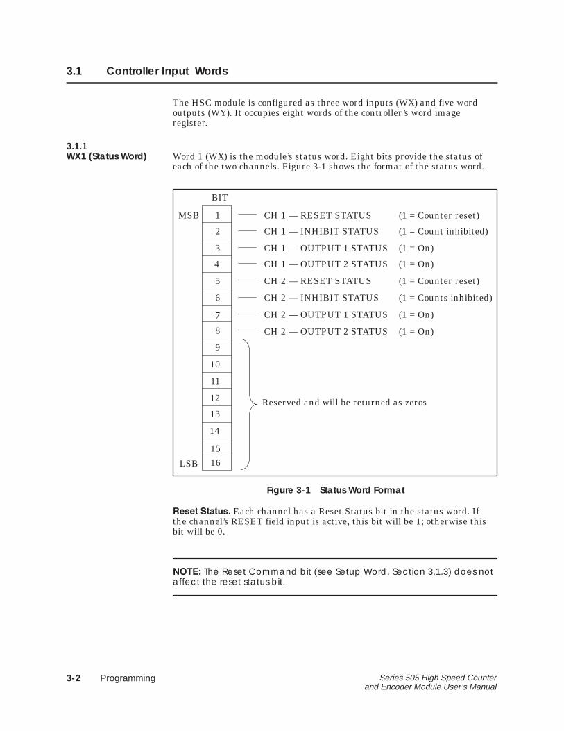
3.1.1WX1 (Status Word) Word 1 (WX) is the module’s status word. Eight bits provide the status of
each of the two channels. Figure 3-1 shows the format of the status word.
9
10
11
12
13
14
15
16
1
2
3
4
5
6
7
8
Reserved and will be returned as zeros
CH 1 — INHIBIT STATUS (1 = Count inhibited)
CH 1 — RESET STATUS
CH 1 — OUTPUT 1 STATUS
(1 = Counter reset)
(1 = On)
CH 1 — OUTPUT 2 STATUS
CH 2 — INHIBIT STATUS
(1 = On)
(1 = Counts inhibited)
CH 2 — RESET STATUS (1 = Counter reset)
CH 2 — OUTPUT 1 STATUS (1 = On)
CH 2 — OUTPUT 2 STATUS (1 = On)
BIT
MSB
LSB
Figure 3-1 Status Word Format
���� � ��� Each channel has a Reset Status bit in the status word. Ifthe channel’s RESET field input is active, this bit will be 1; otherwise thisbit will be 0.
�����The Reset Command bit (see Setup Word, Section 3.1.3) does notaffect the reset status bit.
�
Programming 3-3Series 505 High Speed Counter and Encoder Module User’s Manual
��� � � ��� Each channel has an Inhibit Status bit in the status word. Ifthe channel’s ������� field input is active or if its Inhibit Command bit is 1(see Setup Word, Section 3.1.3), this bit will be 1 and the counter will notcount. Otherwise, this bit will be 0.
�� �� � � ��� Each channel has an Output 1 Status and an Output 2Status bit in the status word. If the corresponding field output is on, the bitwill be 1. Otherwise, the bit will be 0.
3.1.2WX2 and WX3 Word 2 (WX2) contains the current value of the Channel 1 count(Channel Count) register, and Word 3 (WX3) contains the current value of the Channel 2
count register. These values are unsigned integers between 0 and 65,535(inclusive).
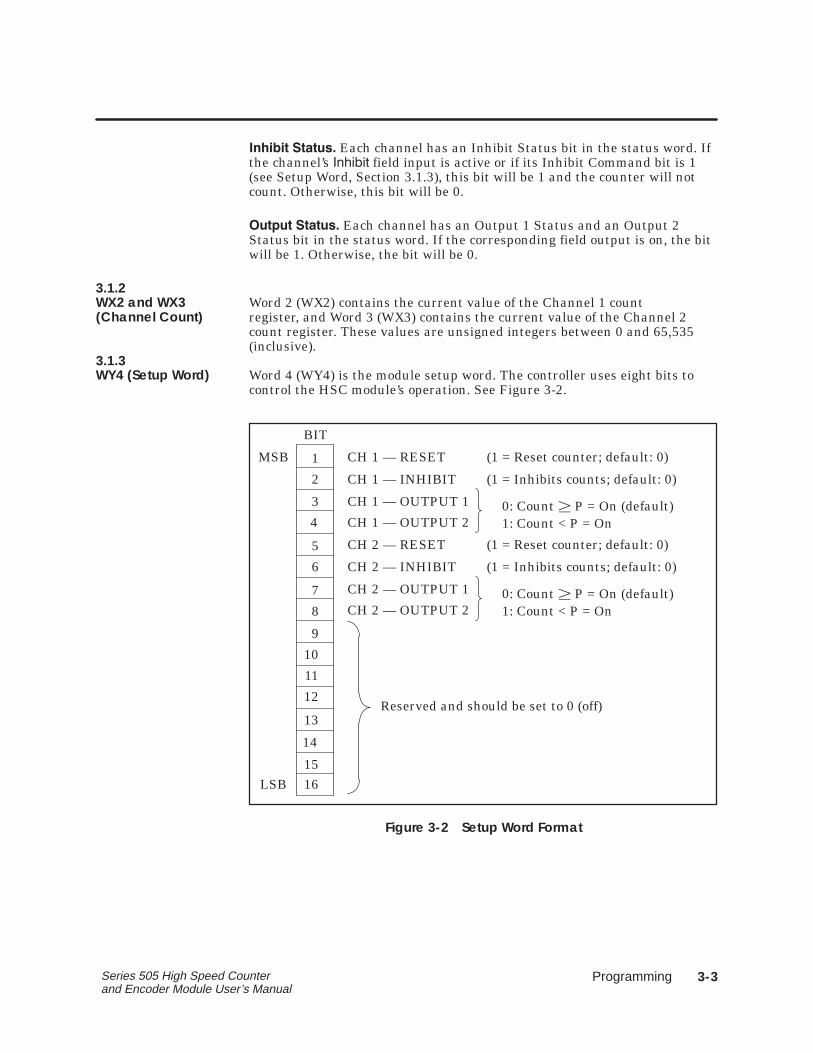
3.1.3WY4 (Setup Word) Word 4 (WY4) is the module setup word. The controller uses eight bits to
control the HSC module’s operation. See Figure 3-2.
9
10
11
12
13
14
1516
1
2
3
4
5
6
7
8
Reserved and should be set to 0 (off)
CH 1 — INHIBIT (1 = Inhibits counts; default: 0)
CH 1 — RESET (1 = Reset counter; default: 0)
CH 1 — OUTPUT 1 0: Count � P = On (default)1: Count < P = OnCH 1 — OUTPUT 2
CH 2 — INHIBIT (1 = Inhibits counts; default: 0)
CH 2 — RESET (1 = Reset counter; default: 0)
CH 2 — OUTPUT 1
CH 2 — OUTPUT 2
BIT
0: Count � P = On (default)1: Count < P = On
MSB
LSB
Figure 3-2 Setup Word Format
Programming3-4 Series 505 High Speed Counter and Encoder Module User’s Manual
Controller Input Words (continued)
���� �������� Both channels have a Reset Command bit. A transitionfrom 0 (off) to 1 (on) of the Reset Command acts as a one-shot (providing amomentary reset of the channel), setting the count to 0. Even though thebit remains 1, counting resumes.
���� �� �������� Both channels have an Inhibit Command bit. When thisbit is set to 1, the channel stops counting.
���� When in the pulse counter mode, if the A or B input is in adifferent state at the beginning and end of an inhibit signal, the countwill change according to the normal counting logic. If both A and Binputs are in different states, the change may be as much as twocounts.
����� ������ The output level bit specifies when the outputs for eachchannel turn on.
� Setting the output level bit to 0 turns the output on when the currentcount is greater than or equal to the preset. If the current count is lessthan the preset, the output is off.
� Setting the output level bit to 1 turns the output on when the currentcount is less than the preset. If the current count is greater than orequal to the preset, the output is off.
3.1.4WY5 – WY8 Words WY5 through WY8 specifies preset values for each channel.(Preset Words) You can specify any value between 0 and 65,535.
� ��� specifies the value for Preset 1, Channel 1.
� ��� specifies the value for Preset 2, Channel 1.
� ��� specifies the value for Preset 1, Channel 2.
� ��� specifies the value for Preset 2, Channel 2.
3.1.5I/O Update In each scan, the controller reads the module WX words before updatingConsideration the WY words. For example, during a scan when the controller resets the
module, the WX word(s) contain counter values existing prior to the reset.
�
Troubleshooting 4-1Series 505 High Speed Counter and Encoder Module User’s Manual
Chapter 4
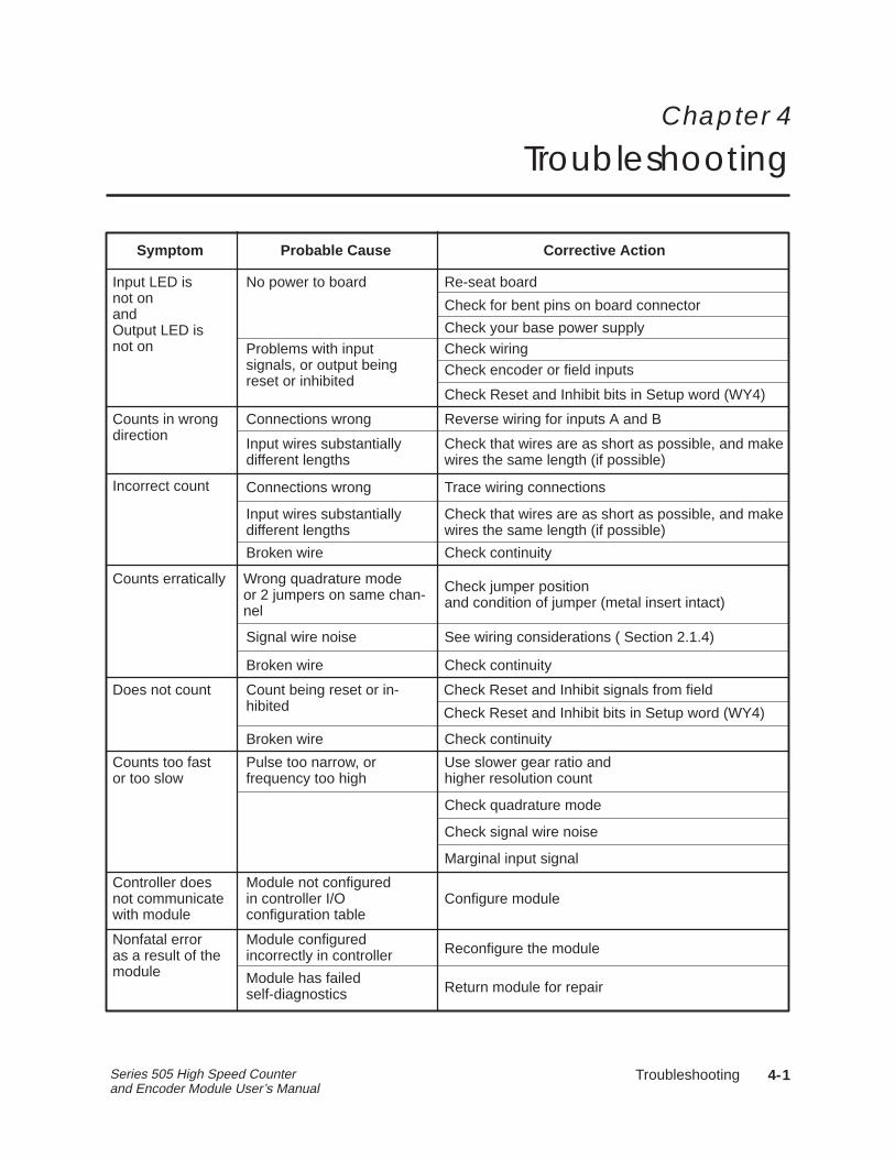
Troubleshooting
Re-seat board
Check jumper positionand condition of jumper (metal insert intact)
Symptom Probable Cause Corrective Action
Input LED isnot onand Output LED isnot on
Signal wire noise
Module not configuredin controller I/O configuration table
Module configured incorrectly in controller
Module has failed self-diagnostics
Nonfatal erroras a result of themodule
See wiring considerations ( Section 2.1.4)
Configure module
Return module for repair
Reconfigure the module
Check your base power supplyCheck wiringCheck encoder or field inputs
Incorrect count Connections wrong
Counts in wrongdirection
Connections wrong
Counts erratically Wrong quadrature modeor 2 jumpers on same chan-nel
Pulse too narrow, orfrequency too high
Use slower gear ratio and higher resolution count
Reverse wiring for inputs A and B
Trace wiring connections
Counts too fastor too slow
Check quadrature mode
Check signal wire noise
Marginal input signal
Does not count Count being reset or in-hibited
Check Reset and Inhibit signals from field
Controller does not communicatewith module
Broken wire Check continuity
Broken wire Check continuity
Broken wire Check continuity
Input wires substantiallydifferent lengths
Check that wires are as short as possible, and makewires the same length (if possible)
Input wires substantiallydifferent lengths
Check Reset and Inhibit bits in Setup word (WY4)
Check for bent pins on board connector
No power to board
Problems with input signals, or output beingreset or inhibited
Check that wires are as short as possible, and makewires the same length (if possible)
Check Reset and Inhibit bits in Setup word (WY4)
4-2 Troubleshooting Series 505 High Speed Counter and Encoder Module User’s Manual
4.1 Checking the Operation of the Module
To check the operation of the module, follow these steps.
����� Module outputs will turn on during this procedure.
1. Using a programming device, force all presets to 0.
2. Reset both counters through the reset signals from your application.
Using the default configuration, the outputs should turn on.
3. Using your programming device, force the presets to any numbergreater than 0.
The outputs should turn off.
����� Before resuming normal operation, clear any words that you haveforced. Otherwise, these words remain forced during operation and couldyield unexpected results.
If you used the setup word to configure the module, then the output followsyour configuration.
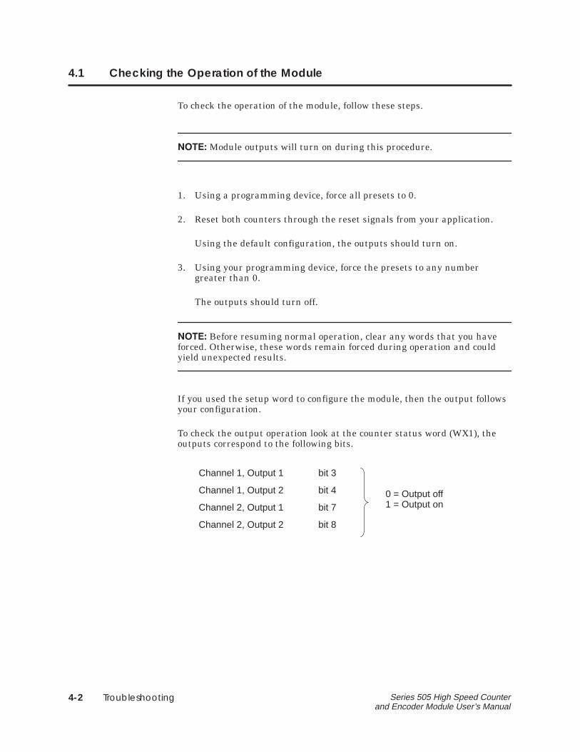
To check the output operation look at the counter status word (WX1), theoutputs correspond to the following bits.
Channel 1, Output 1 bit 3
Channel 1, Output 2 bit 4
Channel 2, Output 1 bit 7
Channel 2, Output 2 bit 8
0 = Output off1 = Output on
�
Applications 5-1Series 505 High Speed Counter and Encoder Module User’s Manual
Chapter 5
Applications
5.1 Sprayer Example 5-2. . . . . . . . . . . . . . . . . . . . . . . . . . . . . . . . . . . . . . . . . . . . . . . . . . 5.1.1 Description 5-2. . . . . . . . . . . . . . . . . . . . . . . . . . . . . . . . . . . . . . . . . . . . . . . . . . . . . . . . . . . . . . 5.1.2 Solution 5-3. . . . . . . . . . . . . . . . . . . . . . . . . . . . . . . . . . . . . . . . . . . . . . . . . . . . . . . . . . . . . . . . .
5.2 Flow Rate Example 5-5. . . . . . . . . . . . . . . . . . . . . . . . . . . . . . . . . . . . . . . . . . . . . . . . 5.2.1 Description 5-5. . . . . . . . . . . . . . . . . . . . . . . . . . . . . . . . . . . . . . . . . . . . . . . . . . . . . . . . . . . . . . 5.2.2 Solution 5-5. . . . . . . . . . . . . . . . . . . . . . . . . . . . . . . . . . . . . . . . . . . . . . . . . . . . . . . . . . . . . . . . .
5.3 Tank Filling Example 5-6. . . . . . . . . . . . . . . . . . . . . . . . . . . . . . . . . . . . . . . . . . . . . . . 5.3.1 Description 5-6. . . . . . . . . . . . . . . . . . . . . . . . . . . . . . . . . . . . . . . . . . . . . . . . . . . . . . . . . . . . . . 5.3.2 Solution 5-6. . . . . . . . . . . . . . . . . . . . . . . . . . . . . . . . . . . . . . . . . . . . . . . . . . . . . . . . . . . . . . . . .
Applications5-2 Series 505 High Speed Counter and Encoder Module User’s Manual
5.1 Sprayer Example
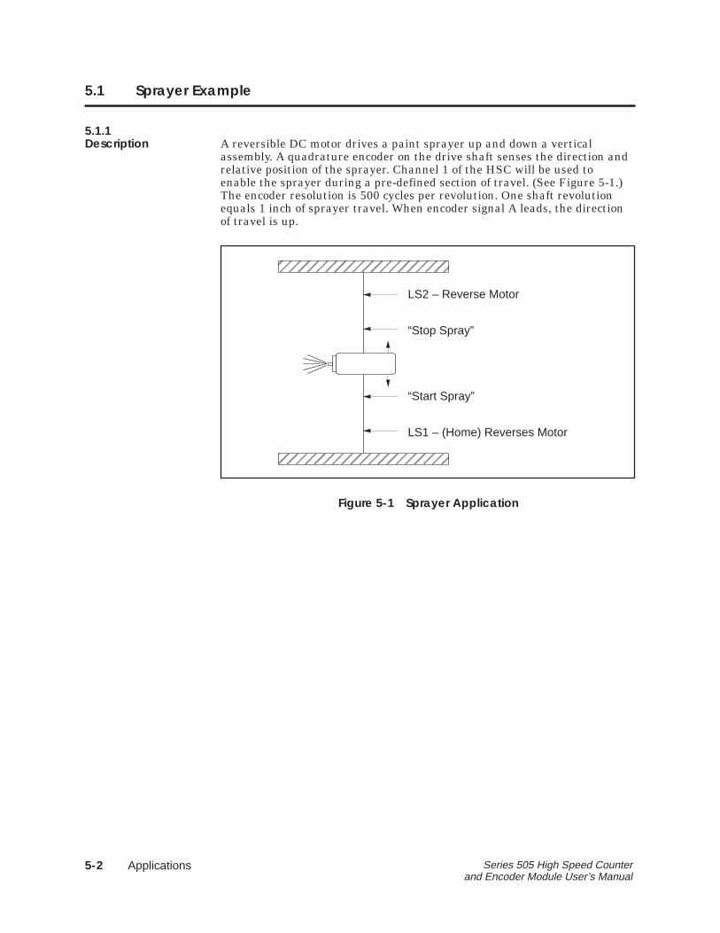
5.1.1Description A reversible DC motor drives a paint sprayer up and down a vertical
assembly. A quadrature encoder on the drive shaft senses the direction andrelative position of the sprayer. Channel 1 of the HSC will be used toenable the sprayer during a pre-defined section of travel. (See Figure 5-1.)The encoder resolution is 500 cycles per revolution. One shaft revolutionequals 1 inch of sprayer travel. When encoder signal A leads, the directionof travel is up.
ÉÉÉÉÉÉÉÉÉÉÉÉÉÉÉÉÉÉÉÉ
ÉÉÉÉÉÉÉÉÉÉ
LS2 – Reverse Motor
“Stop Spray”
“Start Spray”
LS1 – (Home) Reverses Motor
Figure 5-1 Sprayer Application
�
Applications 5-3Series 505 High Speed Counter and Encoder Module User’s Manual
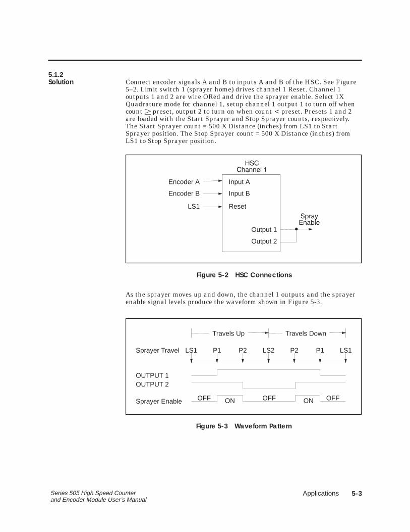
5.1.2Solution Connect encoder signals A and B to inputs A and B of the HSC. See Figure
5–2. Limit switch 1 (sprayer home) drives channel 1 Reset. Channel 1outputs 1 and 2 are wire ORed and drive the sprayer enable. Select 1XQuadrature mode for channel 1, setup channel 1 output 1 to turn off whencount � preset, output 2 to turn on when count � preset. Presets 1 and 2are loaded with the Start Sprayer and Stop Sprayer counts, respectively.The Start Sprayer count = 500 X Distance (inches) from LS1 to StartSprayer position. The Stop Sprayer count = 500 X Distance (inches) fromLS1 to Stop Sprayer position.
Encoder A
Encoder B
LS1
Input A
Input B
Reset
Output 1
Output 2
� ���
�����
���
�������
Figure 5-2 HSC Connections
As the sprayer moves up and down, the channel 1 outputs and the sprayerenable signal levels produce the waveform shown in Figure 5-3.
OFF ON OFF ON OFF
LS1 P1 P2 LS2 P2 P1 LS1
Travels Up Travels Down
Sprayer Travel
OUTPUT 1OUTPUT 2
Sprayer Enable
Figure 5-3 Waveform Pattern
Applications5-4 Series 505 High Speed Counter and Encoder Module User’s Manual
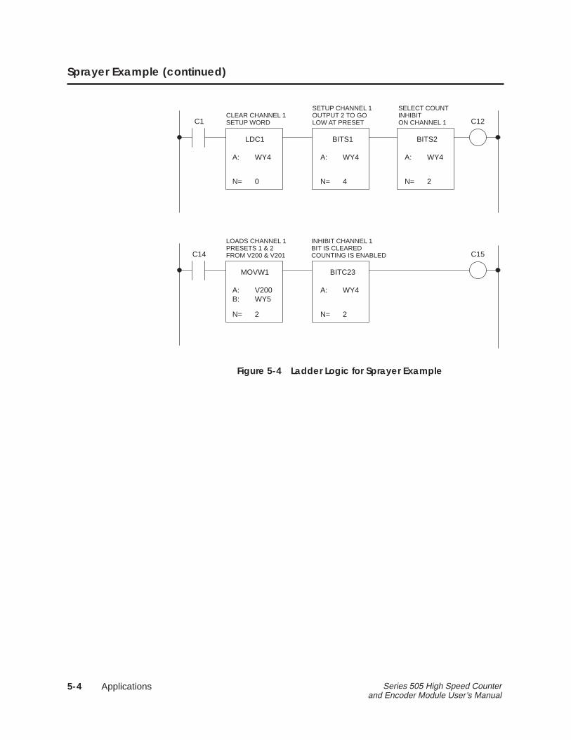
Sprayer Example (continued)
LDC1
A:
N=
WY4
0
BITS1
A:
N=
WY4
4
BITS2
A:
N=
WY4
2
C12C1
MOVW1
A:
N=
V200
2
BITC23
A:
N=
WY4
2
C15C14
B: WY5
CLEAR CHANNEL 1SETUP WORD
SETUP CHANNEL 1OUTPUT 2 TO GOLOW AT PRESET
SELECT COUNTINHIBITON CHANNEL 1
INHIBIT CHANNEL 1BIT IS CLEAREDCOUNTING IS ENABLED
LOADS CHANNEL 1PRESETS 1 & 2FROM V200 & V201
Figure 5-4 Ladder Logic for Sprayer Example
�
Applications 5-5Series 505 High Speed Counter and Encoder Module User’s Manual
5.2 Flow Rate Example
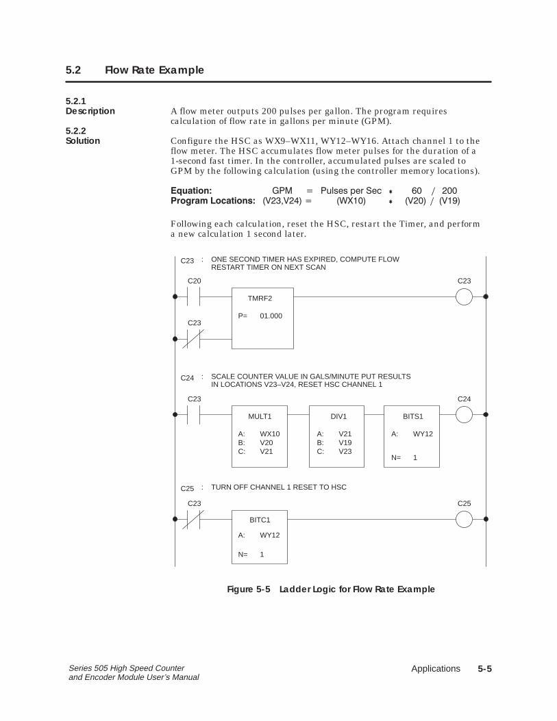
5.2.1Description A flow meter outputs 200 pulses per gallon. The program requires
calculation of flow rate in gallons per minute (GPM).5.2.2Solution Configure the HSC as WX9–WX11, WY12–WY16. Attach channel 1 to the
flow meter. The HSC accumulates flow meter pulses for the duration of a1-second fast timer. In the controller, accumulated pulses are scaled toGPM by the following calculation (using the controller memory locations).
� ������ �� � ������ ��� ��� � � � ���
������ ��������� �������� � ������ � ����� � �����
Following each calculation, reset the HSC, restart the Timer, and performa new calculation 1 second later.
TMRF2
P= 01.000
C23C20
BITC1
A:
N=
WY12
1
C25C23
MULT1
A: WX10
DIV1
A: V21
BITS1
A:
N=
WY12
1
C24C23
C23
C23
C25
C24
: ONE SECOND TIMER HAS EXPIRED, COMPUTE FLOWRESTART TIMER ON NEXT SCAN
: SCALE COUNTER VALUE IN GALS/MINUTE PUT RESULTSIN LOCATIONS V23–V24, RESET HSC CHANNEL 1
: TURN OFF CHANNEL 1 RESET TO HSC
B:C:
V20V21
B:C:
V19V23
Figure 5-5 Ladder Logic for Flow Rate Example
Applications5-6 Series 505 High Speed Counter and Encoder Module User’s Manual
5.3 Tank Filling Example
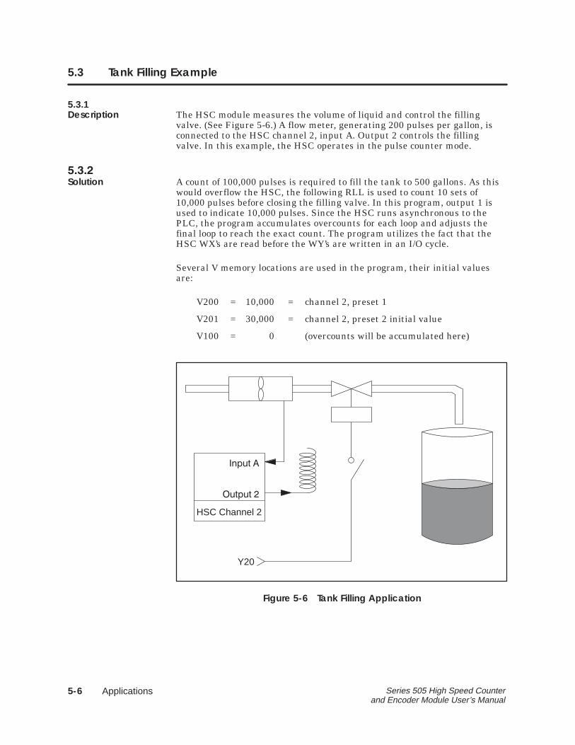
5.3.1Description The HSC module measures the volume of liquid and control the filling
valve. (See Figure 5-6.) A flow meter, generating 200 pulses per gallon, isconnected to the HSC channel 2, input A. Output 2 controls the fillingvalve. In this example, the HSC operates in the pulse counter mode.
�����
Solution A count of 100,000 pulses is required to fill the tank to 500 gallons. As thiswould overflow the HSC, the following RLL is used to count 10 sets of10,000 pulses before closing the filling valve. In this program, output 1 isused to indicate 10,000 pulses. Since the HSC runs asynchronous to thePLC, the program accumulates overcounts for each loop and adjusts thefinal loop to reach the exact count. The program utilizes the fact that theHSC WX’s are read before the WY’s are written in an I/O cycle.
Several V memory locations are used in the program, their initial valuesare:
V200 = 10,000 = channel 2, preset 1
V201 = 30,000 = channel 2, preset 2 initial value
V100 = 0 (overcounts will be accumulated here)
Y20
���� �
���� �
HSC Channel 2
Figure 5-6 Tank Filling Application
�
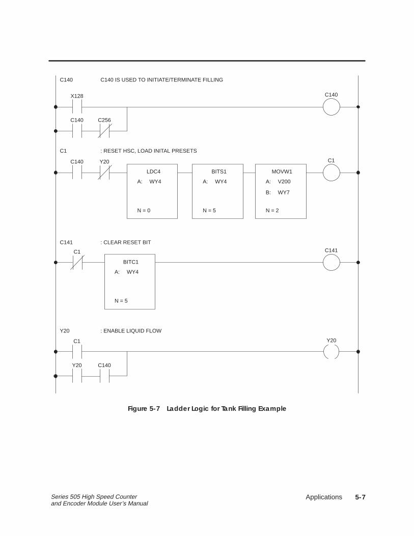
Applications 5-7Series 505 High Speed Counter and Encoder Module User’s Manual
C141
BITC1
A: WY4
N = 5
C140
X128 C140
C140 C256
C140 IS USED TO INITIATE/TERMINATE FILLING
C1
C140 C1
: RESET HSC, LOAD INITAL PRESETS
Y20
LDC4
A: WY4
N = 0
MOVW1
A: V200
N = 2
B: WY7
BITS1
A: WY4
N = 5
C141 : CLEAR RESET BIT
C1
Y20
C1 Y20
Y20 C140
: ENABLE LIQUID FLOW
Figure 5-7 Ladder Logic for Tank Filling Example
Applications5-8 Series 505 High Speed Counter and Encoder Module User’s Manual
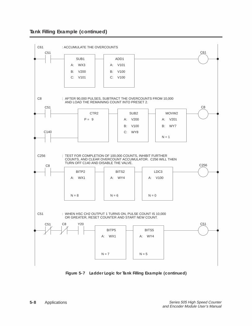
Tank Filling Example (continued)
C51
C8
C51 C8
: AFTER 90,000 PULSES, SUBTRACT THE OVERCOUNTS FROM 10,000AND LOAD THE REMAINING COUNT INTO PRESET 2.
CTR2
P = 9
MOVW2
A: V201
N = 1
B: WY7
SUB2
C51 C8 Y20
C61
SUB1
C61
C51
: ACCUMULATE THE OVERCOUNTS
A: WX3
B: V200
C: V101
ADD1
A: V101
B: V100
C: V100
A: V200
C:
B: V100
WY8C140
C256
C8 C256
: TEST FOR COMPLETION OF 100,000 COUNTS, INHIBIT FURTHERCOUNTS, AND CLEAR OVERCOUNT ACCUMULATOR. C256 WILL THENTURN OFF C140 AND DISABLE THE VALVE.
BITP2
A: WX1
LDC3
A: V100
N = 0
BITS2
A: WY4
N = 6N = 8
BITS5
A: WY4
N = 5
BITP5
A: WX1
N = 7
C51 : WHEN HSC CH2 OUTPUT 1 TURNS ON, PULSE COUNT IS 10,000OR GREATER, RESET COUNTER AND START NEW COUNT.
Figure 5-7 Ladder Logic for Tank Filling Example (continued)
�
Terminal Block Worksheet A-1Series 505 High Speed Counter and Encoder Module User’s Manual
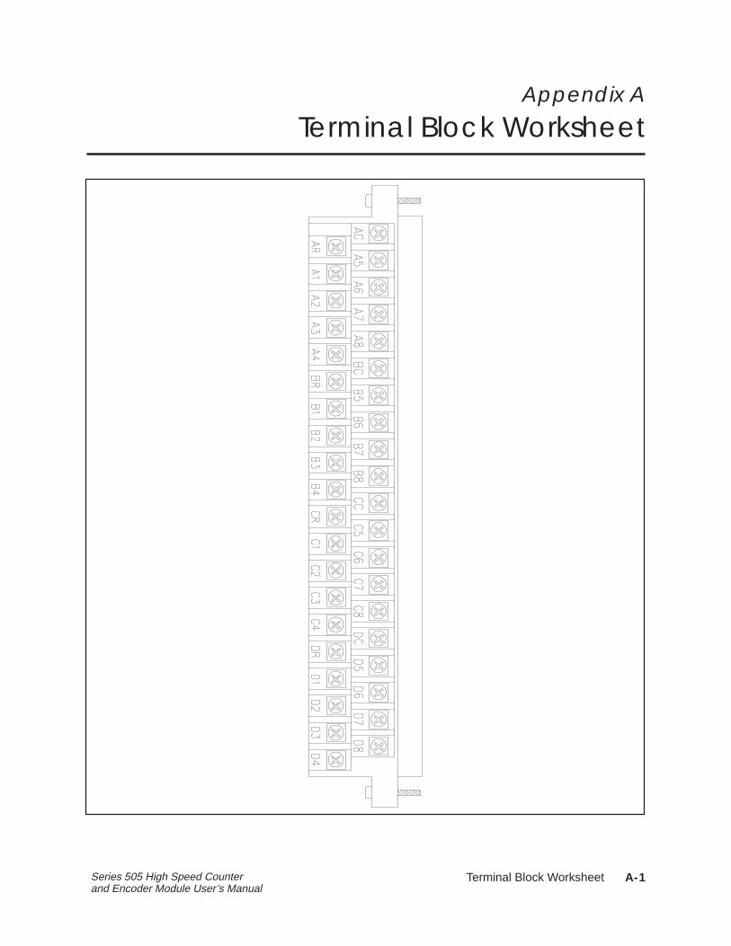
Appendix A
Terminal Block Worksheet
�
Specifications B-1Series 505 High Speed Counter and Encoder Module User’s Manual
Appendix B
Specifications
B.1 Environmental Specifications B-2. . . . . . . . . . . . . . . . . . . . . . . . . . . . . . . . . . . . . .
B.2 Electrical Specifications B-3. . . . . . . . . . . . . . . . . . . . . . . . . . . . . . . . . . . . . . . . . . .
B.3 Additional Compliances B-6. . . . . . . . . . . . . . . . . . . . . . . . . . . . . . . . . . . . . . . . . . .
SpecificationsB-2 Series 505 High Speed Counter and Encoder Module User’s Manual
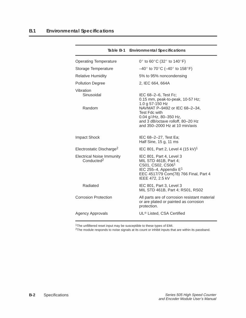
B.1 Environmental Specifications
Table B-1 Environmental Specifications
Operating Temperature 0� to 60�C (32� to 140�F)
Storage Temperature –40� to 70�C (–40� to 158�F)
Relative Humidity 5% to 95% noncondensing
Pollution Degree 2, IEC 664, 664A
VibrationSinusoidal IEC 68–2–6, Test Fc;
0.15 mm, peak-to-peak, 10-57 Hz;1.0 g 57-150 Hz
Random NAVMAT P–9492 or IEC 68–2–34,Test Fdc with0.04 g�/Hz, 80–350 Hz,and 3 dB/octave rolloff, 80–20 Hzand 350–2000 Hz at 10 min/axis
Impact Shock IEC 68–2–27, Test Ea;Half Sine, 15 g, 11 ms
Electrostatic Discharge2 IEC 801, Part 2, Level 4 (15 kV)1
Electrical Noise Immunity IEC 801, Part 4, Level 3Conducted2 MIL STD 461B, Part 4;
CS01, CS02, CS061
IEC 255–4, Appendix E1
EEC 4517/79 Com(78) 766 Final, Part 4IEEE 472, 2.5 kV
Radiated IEC 801, Part 3, Level 3MIL STD 461B, Part 4; RS01, RS02
Corrosion Protection All parts are of corrosion resistant materialor are plated or painted as corrosionprotection.
Agency Approvals UL� Listed, CSA Certified
1The unfilltered reset input may be susceptible to these types of EMI.2The module responds to noise signals at its count or inhibit inputs that are within its passband.
�
Specifications B-3Series 505 High Speed Counter and Encoder Module User’s Manual
B.2 Electrical Specifications
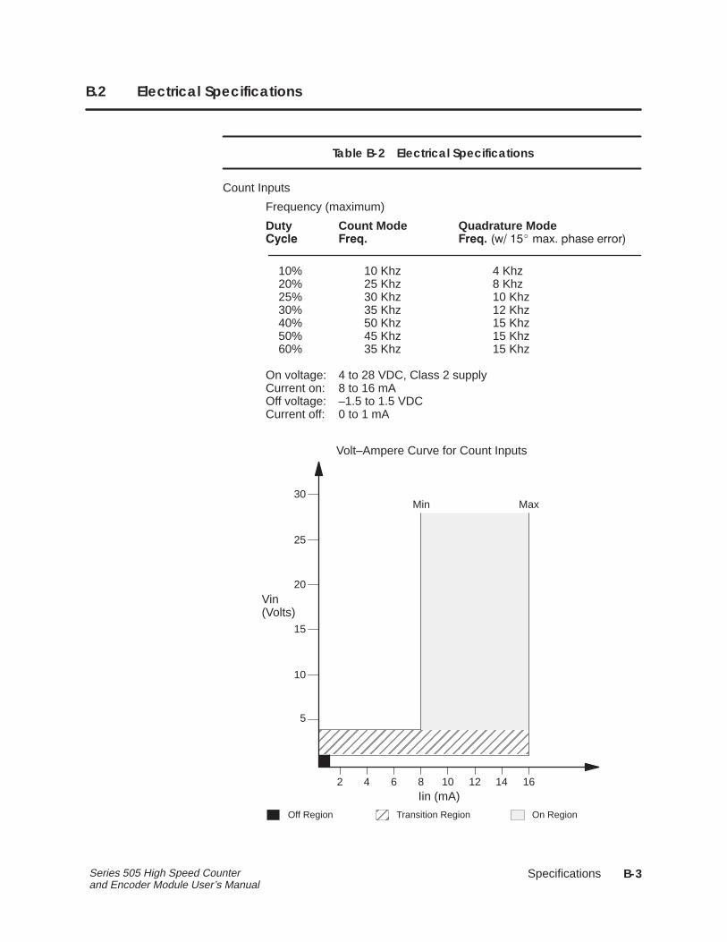
Table B-2 Electrical Specifications
Count Inputs
Frequency (maximum)
Duty Count Mode Quadrature Mode���� ���� ���� ��� ��� ���� �� �����
10% 10 Khz 4 Khz20% 25 Khz 8 Khz25% 30 Khz 10 Khz30% 35 Khz 12 Khz40% 50 Khz 15 Khz50% 45 Khz 15 Khz60% 35 Khz 15 Khz
On voltage: 4 to 28 VDC, Class 2 supplyCurrent on: 8 to 16 mAOff voltage: –1.5 to 1.5 VDCCurrent off: 0 to 1 mA
ÉÉÉÉÉÉÉÉÉÉÉÉÉÉÉÉÉÉÉÉÉÉÉÉÉÉÉÉÉÉÉÉÉÉÉÉ
Volt–Ampere Curve for Count Inputs
2
5
10
15
20
25
30
Vin(Volts)
Iin (mA)
Min Max
4 6 8 10 12 14 16
ÉÉOff Region Transition Region On Region
SpecificationsB-4 Series 505 High Speed Counter and Encoder Module User’s Manual
Electrical Specifications (continued)
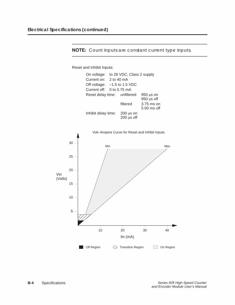
������Count inputs are constant current type inputs.
Reset and Inhibit Inputs:
On voltage: to 28 VDC, Class 2 supplyCurrent on: 2 to 40 mAOff voltage: –1.5 to 1.5 VDCCurrent off: 0 to 0.75 mAReset delay time: unfiltered 950 �s on
950 �s offfiltered 3.75 ms on
5.00 ms offInhibit delay time: 200 �s on
200 �s off
ÉÉÉÉÉÉ
Volt–Ampere Curve for Reset and Inhibit Inputs
10 20 30 40
5
10
15
20
25
30
Vin(Volts)
Iin (mA)
Min Max
ÉÉ
Off Region Transition Region On Region
�
Specifications B-5Series 505 High Speed Counter and Encoder Module User’s Manual
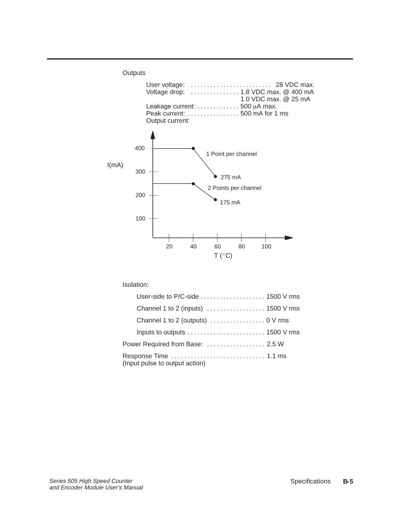
Outputs
User voltage: 28 VDC max.. . . . . . . . . . . . . . . . . . . . . . . . . Voltage drop: 1.8 VDC max. @ 400 mA. . . . . . . . . . . . . . .
1.0 VDC max. @ 25 mALeakage current: 500 �A max.. . . . . . . . . . . . . Peak current: 500 mA for 1 ms. . . . . . . . . . . . . . . . Output current:
400
300
200
100
20 40 60 80 100
275 mA
175 mA
I(mA)
T (�C)
1 Point per channel
2 Points per channel
Isolation:
User-side to P/C-side 1500 V rms. . . . . . . . . . . . . . . . . . . .
Channel 1 to 2 (inputs) 1500 V rms. . . . . . . . . . . . . . . . . .
Channel 1 to 2 (outputs) 0 V rms. . . . . . . . . . . . . . . . .
Inputs to outputs 1500 V rms. . . . . . . . . . . . . . . . . . . . . . . .
Power Required from Base: 2.5 W. . . . . . . . . . . . . . . . . .
Response Time 1.1 ms. . . . . . . . . . . . . . . . . . . . . . . . . . . . . (Input pulse to output action)
SpecificationsB-6 Series 505 High Speed Counter and Encoder Module User’s Manual
B.3 Additional Compliances
In addition, the system complies with applicable requirements of VerbandDeutscher Elektrotechniker (VDE) 0160: Electrical Equipment
Series 505 products have been developed with consideration of the draftstandard for programmable controllers as described in the proposedstandard of the International Electrotechnical Commission Committee(IEC–65A/WG6, Part 2).
Information concerning product reliability and compliance to the IEC orother standards can be provided upon request. Contact your SiemensIndustrial Automation, Inc. distributor for additional information.

Customer Registration
We would like to know what you think about our user manuals so that we can serve you better.How would you rate the quality of our manuals?
Excellent Good Fair Poor
AccuracyOrganizationClarityCompletenessOverall designSizeIndex
Would you be interested in giving us more detailed comments about our manuals?
Yes! Please send me a questionnaire.
No. Thanks anyway.
Your Name:
Title:
Telephone Number: ( )
Company Name:
Company Address:
Manual Name: High Speed Counter and Encoder Module User Manual Edition: Second
Manual Assembly Number: 2586546-0019 Date: 12/92
Order Number: PPX:505–8113–2

BUSINESS REPLY MAILFIRST CLASS PERMIT NO.3 JOHNSON CITY, TN
FOLD
FOLD
POSTAGE WILL BE PAID BY ADDRESSEE
NO POSTAGENECESSARYIF MAILED
IN THEUNITED STATES
SIEMENS INDUSTRIAL AUTOMATION, INC. 3000 BILL GARLAND RD.P.O. BOX 1255JOHNSON CITY TN 37605–1255
ATTN: Technical Communications M/S 3519
�
Index-1
Index
AAssistance, 2-2
CConfiguration
selecting, 2-10updating, 2-10
Configuringjumpers, 2-5User Options, 2-10
Count input, 1-4
Count rate, 1-2
Counter mode, 1-7
DDouble-count quadrature, 1-9
EElectrical specifications, B-3
Environmental specifications, B-2
FFeatures, 1-2
HHandling the HSC, 2-2
II/O
address, 2-10configuration chart, 2-11definition chart, 2-10
I/O base, 2-7
Inhibit, 1-2, 1-4
Input, 1-4count, 1-4inhibit, 1-4reset, 1-4Specifications, B-3
JJumper, 2-5
Jumper pins, 2-5
LLED, 1-2
A input, 1-6B input, 1-6
LED indicator, 1-6
Logging module into controller, 2-10
OOutput, 1-5
open collector, 1-5specifications, B-5
PPowering up the module, 2-8
Pulse counter mode, 1-7
Pulse width, 1-2, B-4
Index-2
QQuadrature Mode, quadruple count, 1-10
Quadrature modedouble-count, 1-9single-count, 1-8
Quadruple count, quadrature mode, 1-10
RReferences, 2-2
Reset, 1-2, 1-4
SSingle-count quadrature, 1-8
Static electricity, 2-2
TTerminal block, 2-8
wiring diagram, 2-9worksheet, 2-8
UUsing status words, 3-2
WWiring, 2-3, 2-8
considerations, 2-3

SIMATIC is a registered trademark of Siemens AG.
Series 505 and TISOFT are trademarks of Siemens Industrial Automation, Inc.
Texas Instruments and TI are registered trademarks of Texas Instruments Incorporated.
TI505, TI525, TI535, and TI545 are trademarks of Texas Instruments Incorporated.
UL is a registered trademark of Underwriters Laboratories.