Embed Size (px)
Citation preview

USER MANUAL
HEAT (ENERGY) RECOVERY
VENTILATION UNIT
Vents Frigate HRV 120 S
Vents Frigate ERV 120 S

2Frigate HRV(ERV) 120 SFrigate HRV(ERV) 120 S
IntroductionUseIncluded in the BoxDesignation Key Technical Data Safety Requirements Design and Operation Mounting and Installation Guidelines Condensate DrainageConnection to Power SupplyUnit Control System Maintenance Troubleshooting Storage and Transportation Warranty
CONTENT
3333456789
1011121313
3
INTRODUCTION
USE
INCLUDED IN THE BOX
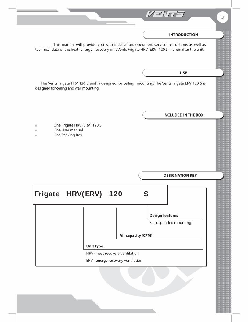
The Vents Frigate HRV 120 S unit is designed for ceiling mounting. The Vents Frigate ERV 120 S is designed for ceiling and wall mounting.
This manual will provide you with installation, operation, service instructions as well as technical data of the heat (energy) recovery unit Vents Frigate HRV (ERV) 120 S, hereinafter the unit.
One Frigate HRV (ERV) 120 S One User manual One Packing Box
Unit type
HRV - heat recovery ventilation
ERV - energy recovery ventilation
Air capacity [CFM]
Frigate HRV(ERV) 120 S
DESIGNATION KEY
Design features
S - suspended mounting

4Frigate HRV(ERV) 120 SFrigate HRV(ERV) 120 S
TECHNICAL DATA
Vents Frigate HRV (ERV) 120 S unit is designed for indoor installation and operation at the ambient air temperature ranging from +34 °F (+1 °С) up to +122 °F (50 °С) and RH max. 80%.
Ingress Protection rating: IP44 for the unit motors; IP 22 for the assembled unit connected to air ducts.
The Vents Frigate HRV 120 S unit net weight is 53 lbs. (24 kg). The Vents Frigate ERV 120 S unit net weight is 51 lbs. (23 kg).
The unit series designation, basic overall and connecting dimensions are shown in fi g. 1.The product design is periodically updated. Your unit may slightly diff er from the model described here.
10"5 1/16"
1 1/2" 5"
20 1/16"23 1/8"
7"11
/16"
1/2" 21"
24 7/8"
4"
20 1/16"
5"
7"1/
2"11
/16"
10"
23 1/8"
5 1/16"21"
24 7/8"
Vents Frigate HRV 120 S
Vents Frigate ERV 120 S
Fig. 1. Overall and connecting dimensions

5
Do not!
• Under no circumstances should the unit be operated in an environment with
temperatures exceeding the technical data indicated on the motor name plate.
• Do not connect a clothes dryer or other irrelevant equipment to the unit.
SAFETY REQUIREMENTS
During installation and operation, observe all codes and safety standards for your locale.Safe grounding must be provided! Check the unit for possible damages prior to connecting it to power supply. Make sure the unit does
not contain any foreign objects inside the case. Electrical connections should only be done by a qualifi ed electrician.
Warning!
Whenever the heat recovery unit is installed, serviced, moved, or repaired it
must be disconnected from the main power source.

6Frigate HRV(ERV) 120 SFrigate HRV(ERV) 120 S
1. Supply fan.2. Extract fan.3. Plate air-to-air heat recovery core of cross fl ow type.
Frigate ERV 120 S − made of polymerized cellulose. Frigate HRV 120 S − made of plastic.
4. G4 supply air fi lter.5. G4 extract air fi lter.6. Defrost thermostat. 7. Control unit.8. Drain pan (applicable only for Frigate HRV 120 S).9. Drain pipe (applicable only for Frigate HRV 120 S).
DESIGN AND OPERATION
STALE AIR FROM ROOM FRESH AIR FROM OUTSIDE
UTILIZED EXHAUST AIRAIR SUPPLIED TO ROOM
1
2 3 45
6
7
8 9
Fig. 2. Design and operation

7
The Frigate ERV 120 S unit is suitable also for wall mounting by means of the fi xing bracket that is fi xed with three screws and expansion bellows, Fig. 4.
MOUNTING AND INSTALLATION GUIDELINES
Be sure to provide suffi cient service access while installing the unit. Fix the unit to the ceiling by means of the belts to be rigidly fi xed to a horizontal plane, Fig. 3 or by means of the threaded rods and expansion anchors to be inserted in the ceiling.
Fig. 4. Unit wall mounting
This installation example is applicable only for Frigate ERV 120 S
min
2”
Fig. 3. Vents Frigate HRV 120 S, Vents Frigate ERV 120 S unit ceiling mounting

8Frigate HRV(ERV) 120 SFrigate HRV(ERV) 120 S
CONDENSATE DRAINAGE
Vents Frigate HRV 120 S includes a drain pipe for condensed water drainage, Fig. 5. Connect the drain pipe 1, the U-trap 3 (not included) and the sewage system 5 with hoses 2, 4
made of metal, plastic or rubber with the minimum hose slope angle 3°. Fill the system with water prior to connecting the unit to power supply and make sure the U-trap
is always fi lled with water. Check the drain system for correct operation and unhampered drainage to prevent condensed water accumulation inside the unit and overfl ow.
The unit is designed for indoor installation and operation at the temperatures above 32 °F (0 °C). If the expected ambient temperatures are below this point, the drain system must be heat-insulated and frost protected.
min 3°
1
3
5
2
4
Fig. 5. Condensate drainage

9
CONNECTION TO POWER SUPPLY
Disconnect the unit from power supply before connection and installation
operations. Electrical wiring should only be performed by a qualifi ed electrician. The nominal
electric parameters are shown on the name plate. Warranty will not cover equipment damage
or failure that is caused by improper installation.
The unit is rated for connection to 120 V / 60 Hz power supply source. The unit is supplied with a pre-wired power cable and an adapter. It is suitable for connection to any
standard grounded outlet. The cutout fuse is used for overload protection in case of an overload or a short circuit. To replace the
cutout fuse disconnect the unit from power supply source, troubleshoot an overload or a short circuit and then replace the cutout fuse. Check the unit for operation.
Refer to Fig. 6 for electrical connections.In case of freezing danger the integrated frost protection thermostat TS1, Fig. 6, stops the supply fan
to let warm extract air stream warm up the hear recovery core. The thermostat temperature set point is adjusted by positioning the control thermostat dial not
below the minimum thermostat response temperature. The thermostat settings are individually adjustable and are determined by the unit application. The recommended thermostat set point is 37 °F (+3 °С) and it is set by default.
РЕL N
Kon 1Kon 2PE M1PE M2Brown M1Cap1
Black M1Cap1
Black M2Cap2
Brown M2Cap2
Blue M1TermTermBlue M2
Х1
Х2
Х3SW1
123
Сap1
Сap2
TS1
М1FAN MOTOR
М2FAN MOTOR
t0
SW2
LowStand byMed
1
К1 К2 К3
2
9 10
11
Setup of Low Setup of Med
termostat
LowMedG0High
~24VPE
Two wirecontrol
9
2
10
2
11
34Y/GY/G5
1617
612
1819
87
141513
C2
~24V
~120V
Х5.1Х5.2
Х6.1
Х6.2
RedRed
WhiteWhite
TR1
GreenBlack
White
120V 60Hz
123456
12345678910111213141516Х4
W1
Fig. 6. Wiring the unit

10Frigate HRV(ERV) 120 SFrigate HRV(ERV) 120 S
Set the three-position switch into the Stand by position to activate the remote control.
Fig. 7. Unit control
External controls compatible with the unit: 1. Remote control (Thermostat).
Remote control (thermostat) functions: Unit turning on/off Setting air fl ow Displaying indoor air temperature
2. CO2 sensor
Recommended for use in offi ce buildings and public premises. When carbon dioxide concentration exceeds the set point, the unit changes into the High Speed Mode.
3. Humidistat
The humidistat is used for indoor humidity control. When indoor humidity rises above the set point, the unit changes into the High Speed Mode and runs with the high speed until the humidity level falls down below the set point. The humidity set point is adjustable.
Three-position mode switch
Contacts for remote control connection
UNIT CONTROL
The unit is controlled using a three-position switch, Fig. 7. It enables operation of the unit in the Low Speed Mode, Medium Speed Mode or Standby Mode, thus providing total air quality control. Up to fi ve external controls may be connected to the terminals 2 and 11, Fig. 6. If the connected control is activated, the unit changes into the High Speed Mode.

11
MAINTENANCE
Regular maintenance should be performed every 3 months as follows: 1. Filter maintenance.
Dirty fi lters increase air resistance and reduce supplied air volume to the room. Clean the fi lters as often as required, but at least 3-4 times per year. Clean the
fi lter with a vacuum cleaner or fl ush it with water. Replace the fi lter after the second cleaning. Contact your Seller for new fi lters.
2. Heat recovery core maintenance (once per year).
The regular fi lter maintenance may not completely prevent dust ingress into the heat recovery core. The heat recovery core must be regularly cleaned to maintain high heat recovery effi ciency. The clean the Vents Frigate ERV 120 S heat recovery core made of polymerised cellulose remove it from the unit and clean it with a vacuum cleaner. Do not use water, abrasive detergents, aggressive solvents and sharp objects. Re-install the heat recovery core back into the unit after cleaning. The clean the Vents Frigate HRV 120 S heat recovery core made of plastic remove it from the unit and wash it with soap water. Let the heat recovery core dry out and re-install it into the unit.
3. Fan maintenance (once per year).
Regular fi lter and heat recovery core maintenance may not completely prevent dust ingress into the unit fans. Clogged fi lter reduce supplied air volume to the room.
Clean the fans with a soft cloth or a brush. No water and abrasive detergent, sharp objects or solvents are allowed for cleaning to prevent the impeller damage.
4. Drain line maintenance (once per year).
The drain line may get clogged by extracted particles. Check the drain line functioning by fi lling the drain pan with water and clean the drain line if required.
5. Intake grille maintenance (twice per year).
The intake grille may get clogged with leaves and other outdoor pollutants. Check the intake grille twice per year and clean as required.
6. Air ductworks maintenance (once in 5 years).
If degraded performance is still noticeable after following all maintenance guidelines it is recommended that the ductwork be checked and cleaned if necessary.
4. Mechanical timer In case of the timer activation the unit changes into the High Speed Mode.
5. Switch
As the switch is turned ON the unit changes into the High Speed Mode and reverts to the permanent Low Speed Mode when the switch in turned OFF.

12Frigate HRV(ERV) 120 SFrigate HRV(ERV) 120 S
TROUBLESHOOTING
Troubles and troubleshooting
Trouble Probable reason Remedy
The fan is not started
Not power supply.Check connection to power supply. Troubleshoot connection error if required.
Fuse blowing.Disconnect the unit from power supply. Troubleshoot the connection error, replace the
Low supply air temperature
Extract fi lter clogging. Clean or replace the extract fi lter.
Heat recovery core freezing.
Check the heat recovery core for icing. If the heat recovery surface is iced, turn the unit off and let ice melt. Check the thermostat settings to prevent the heat recovery core icing.
Low air fl ow
Low set fan speed. Check the speed control dial position. Dirty fi lters, impellers, heat recovery core.
Clean or replace the fi lters. Clean the fans and the heat recovery core.
Dirty or damaged ventilation system.
Make sure the diff users and the louver shutters are opened. Check functioning of the extract hood and the supply grille and clean if required. Make sure the air ducts are intact and clean.
Noise, vibration Dirty impeller. Clean the impeller.Loose fan screw connection. Tighten the screws.
Water leakageObject stuck in the drain line, damaged or wrong mounted drain line.
Clean the drain line if required. Check the drain slope, U-trap and matching the temperature conditions.

13
WARRANTY
WARRANTY
Production meets standard operating requirements in the USA and Canada.VENTS US warrants to the original purchaser of the HRV (ERV) 120 S unit that it will be free from defects in materials or workmanship for a period of 60 months from the date of original purchase. The VENTS US warrants to the original purchaser of the HRV (ERV) 120 S unit that the integrated control unit will be free from defects in materials and workmanship for a period of 24 months from the date of origi-nal purchase. THERE ARE NO OTHER WARRANTIES, EXPRESS OR IMPLIED, INCLUDING, BUT NOT LIMITED TO, IMPLIED WARRANTIES OF MERCHANTABILITY OR FITNESS FOR A PARTICULAR PURPOSE. During the stated warranty period, VENTS US will, at its option, repair or replace, without charge, any product or part which is found to be defective under normal use and service. This warranty does not cover (a) nor-mal maintenance and normal service or (b) any products or parts which have been subject to misuse, negligence, accident, improper maintenance or repair (other than by VENTS US), faulty installation or negligence, accident, improper maintenance or repair (other than by VENTS US), faulty installation or installation contrary to recommended installation instructions. Labor to remove and replace products is not covered. The duration of any implied warranty is limited to the time period specifi ed for the express warranty. Some states do not allow limitations on how long an implied warranty lasts, so the above limitation may not apply to you. VENTS US OBLIGATION TO REPAIR OR REPLACE, AT VENTS US OPTION, SHALL BE THE PURCHASER’S SOLE AND EXCLUSIVE REMEDY UNDER THIS WARRANTY. VENTS US SHALL NOT BE LIABLE FOR INCIDENTAL, CONSEQUENTIAL OR SPECIAL DAMAGES ARISING OUT OF OR IN CON-NECTION WITH PRODUCT USE OR PERFORMANCE. Some states do not allow the exclusion or limitations of incidental or consequential damages, so the above limitation or exclusion may not apply to you. This warranty gives you specifi c legal rights, and you may also have other rights which vary from state to state. This warranty supersedes all prior warranties. If proof of sales date is absent, warranty period is calculated from the production date.
The unit can be exchanged at the following address:Bodor Vents, LLC DBA: VENTS-US11013 Kenwood Road Cincinnati, Ohio 45242Phone: (513)348-3853e-mail: [email protected] follow guidelines in this manual for product problem-free operation.
STORAGE AND TRANSPORTATION
Risk of injury when lifting and installing the unit. Get a helper and wear eye protection. Keep the unit a dry, weather protected premise in the manufacturer’s original packing box in a clean environment.Protect the unit against possible harmful environmental impact until it is fi nally mounted. We do not recommend storing of the unit longer than one year.Keep the duly temperature and humidity conditions in the stock environment.Connection of the unit to power mains is allowed only in 2 hours since its keeping in an premise with the room temperature.

V-US101(FRIGATE_HRV-ERV120S)EN-04


![(ID01)cQ] - symmetry-us.com](https://img.pdfslide.us/doc/110x75/61ee4095b6e83e4b007729f2/id01cq-symmetry-uscom.jpg)