Embed Size (px)
Citation preview
Proterra™
SERVICE MANUALAdvance models: 13300107 (Battery) 13300106 (3 cyl Diesel) 13300109 (3 cyl LPG) 13300108 (3 cyl Gasoline)
33020374(1)2009-07

SERVICE MANUAL ENGLISH
Proterra™ 33020374(1)2009-07 1
GENERAL INFORMATION .............................................................................................................................................. 5REFERENCES ................................................................................................................................................................................ 5MACHINE LIFTING ......................................................................................................................................................................... 5MACHINE TRANSPORTATION ....................................................................................................................................................... 5PUSHING/TOWING THE MACHINE ............................................................................................................................................... 5ACCESSORIES/OPTIONS .............................................................................................................................................................. 6OTHER AVAILABLE MANUALS ...................................................................................................................................................... 6SAFETY ........................................................................................................................................................................................... 6SYMBOLS ....................................................................................................................................................................................... 6GENERAL INSTRUCTIONS ............................................................................................................................................................ 7PARKING BRAKE ............................................................................................................................................................................ 9TECHNICAL DATA ........................................................................................................................................................................... 9DIMENSIONS .................................................................................................................................................................................11MAINTENANCE ............................................................................................................................................................................. 12SCHEDULED MAINTENANCE TABLE [Battery] ........................................................................................................................... 12SCHEDULED MAINTENANCE TABLE [Diesel / LPG / Gasoline] ................................................................................................. 13MACHINE NOMENCLATURE ....................................................................................................................................................... 14MACHINE NOMENCLATURE ....................................................................................................................................................... 14OPERATING CONTROLS ............................................................................................................................................................. 17
SWEEPING SYSTEM .................................................................................................................................................... 19TROUBLESHOOTING [All versions] ............................................................................................................................................. 19MAIN BROOM HEIGHT CHECK AND ADJUSTMENT [All versions] ............................................................................................ 20MAIN BROOM LONGITUDINAL PRESSURE ADJUSTMENT [All versions] ................................................................................. 21SIDE BROOM HEIGHT CHECK AND ADJUSTMENT [All versions] ............................................................................................. 22MAIN BROOM DISASSEMBLY/ASSEMBLY [All versions] ............................................................................................................ 23SIDE BROOM DISASSEMBLY/ASSEMBLY [All versions] ............................................................................................................ 25SIDE AND MAIN BROOM CHECK VALVE DISASSEMBLY/ASSEMBLY [All versions] ................................................................ 26MAIN BROOM MOTOR DISASSEMBLY/ASSEMBLY [All versions] ............................................................................................. 27SIDE BROOM MOTOR DISASSEMBLY/ASSEMBLY [All versions] .............................................................................................. 30SIDE BROOM HYDRAULIC LIFTING CYLINDER DISASSEMBLY/ASSEMBLY [All versions] .................................................... 31MAIN BROOM HYDRAULIC LIFTING CYLINDER DISASSEMBLY/ASSEMBLY [All versions] .................................................... 33
SKIRT ............................................................................................................................................................................. 35SKIRT HEIGHT AND OPERATION CHECK [All versions]............................................................................................................. 35SIDE SKIRT DISASSEMBLY/ASSEMBLY [All versions] ............................................................................................................... 37REAR SKIRT DISASSEMBLY/ASSEMBLY [All versions] .............................................................................................................. 40FRONT SKIRT AND SIDE GASKET DISASSEMBLY/ASSEMBLY [All versions] .......................................................................... 41
TABLE OF CONTENTS
ENGLISH SERVICE MANUAL
2 33020374(1)2009-07 Proterra™
DUST AND DEBRIS COLLECTION SYSTEM .............................................................................................................. 43TROUBLESHOOTING [All versions] ............................................................................................................................................. 43FILTER SHAKER OPERATION CHECK [All versions] .................................................................................................................. 44PANEL FILTER DISASSEMBLY/ASSEMBLY AND CLEANING [All versions] ............................................................................... 44CLOSED POCKET FILTER CLEANING (WITHOUT REMOVING IT FORM THE MACHINE) [All versions] ................................ 46CLOSED POCKET FILTER DISASSEMBLY/ASSEMBLY AND CLEANING [All versions] ............................................................ 48HOPPER CLOSURE CHECK AND ADJUSTMENT [All versions] ................................................................................................. 50VACUUM FAN MOTOR ELECTRICAL INPUT CHECK [All versions] ........................................................................................... 52VACUUM FAN DISASSEMBLY/ASSEMBLY [All versions] ............................................................................................................ 53PANEL FILTER SHAKER MOTOR DISASSEMBLY/ASSEMBLY [All versions] ............................................................................. 55CLOSED POCKET FILTER SHAKER MOTOR DISASSEMBLY/ASSEMBLY [All versions] ......................................................... 57HOPPER DOOR OPENING/CLOSING HYDRAULIC CYLINDER DISASSEMBLY/ASSEMBLY [All versions] ............................ 59HOPPER LIFTING HYDRAULIC CYLINDER DISASSEMBLY/ASSEMBLY [All versions] ............................................................ 61
DUST CONTROL SYSTEM ........................................................................................................................................... 67SYSTEM DIAGRAM [All versions] ................................................................................................................................................. 67TROUBLESHOOTING ................................................................................................................................................................... 67NOZZLE AND FILTER CLEANING [All versions] .......................................................................................................................... 68WATER FILTER DISASSEMBLY/ASSEMBLY AND CLEANING [All versions] .............................................................................. 69WATER TANK DISASSEMBLY/ASSEMBLY [All versions] ............................................................................................................ 70WATER PUMP DISASSEMBLY/ASSEMBLY [All versions] ........................................................................................................... 72
STEERING SYSTEM ..................................................................................................................................................... 73STEERING ASSEMBLY BEARING GREASING [All versions] ...................................................................................................... 73STEERING ASSEMBLY TAPER BEARING CHECK AND ADJUSTMENT [All versions] .............................................................. 74STEERING ASSEMBLY REMOVAL/INSTALLATION [All versions] ............................................................................................... 75STEERING WHEEL DISASSEMBLY/ASSEMBLY [All versions] ................................................................................................... 78POWER STEERING ASSEMBLY REMOVAL/INSTALLATION [All versions] ................................................................................ 79HYDRAULIC STEERING CYLINDER DISASSEMBLY/ASSEMBLY [All versions] ........................................................................ 80
BRAKE SYSTEM ........................................................................................................................................................... 81PARKING BRAKE AND SERVICE BRAKE CHECK AND ADJUSTMENT [All versions] ............................................................... 81BRAKE DISASSEMBLY/ASSEMBLY [All versions] ....................................................................................................................... 84
DRIVE SYSTEM ............................................................................................................................................................. 85TROUBLESHOOTING [All versions] ............................................................................................................................................. 85FORWARD/REVERSE GEAR PEDAL NEUTRAL POSITION CHECK AND ADJUSTMENT [All versions] .................................. 86REAR WHEEL DISASSEMBLY/ASSEMBLY [All versions] ............................................................................................................ 90FRONT WHEEL DISASSEMBLY/ASSEMBLY [All versions] ......................................................................................................... 91DRIVE SYSTEM MOTOR DISASSEMBLY/ASSEMBLY [All versions] .......................................................................................... 92
SERVICE MANUAL ENGLISH
Proterra™ 33020374(1)2009-07 3
MOTOR .......................................................................................................................................................................... 95OVERVIEW [Battery] ..................................................................................................................................................................... 95MAIN MOTOR ELECTRICAL INPUT CHECK [Battery] ................................................................................................................. 95MAIN MOTOR CARBON BRUSH REPLACEMENT [Battery] ....................................................................................................... 96MAIN MOTOR COOLING FAN REPLACEMENT [Battery] ............................................................................................................ 97MAIN MOTOR REMOVAL/REPLACEMENT [Battery] ................................................................................................................... 98
ENDOTHERMIC ENGINE .............................................................................................................................................. 99OVERVIEW [Diesel / LPG / Gasoline] ........................................................................................................................................... 99COOLANT RADIATOR FINS CHECK [Diesel / LPG / Gasoline] ................................................................................................. 100AIR FILTER DISASSEMBLY/ASSEMBLY [Diesel / LPG / Gasoline] ........................................................................................... 101COOLING FAN BELT DISASSEMBLY/ASSEMBLY [Diesel / LPG / Gasoline] ............................................................................ 102FUEL FLOAT DISASSEMBLY/ASSEMBLY [Diesel / Gasoline] ................................................................................................... 105
OTHER SYSTEMS ....................................................................................................................................................... 107CHECKING FOR LEAKS AND TIGHTENING OF SCREWS AND NUTS [All versions] .............................................................. 107REAR HOOD DISASSEMBLY/ASSEMBLY [All versions] ........................................................................................................... 108DRIVER’S SEAT DISASSEMBLY/ASSEMBLY [All versions] .......................................................................................................110HYDRAULIC CYLINDER JOINT GREASING [All versions] .........................................................................................................111
HYDRAULIC SYSTEM ................................................................................................................................................. 113TROUBLESHOOTING ..................................................................................................................................................................113HYDRAULIC DIAGRAM ...............................................................................................................................................................113HYDRAULIC DIAGRAM [Battery] .................................................................................................................................................114HYDRAULIC DIAGRAM [Diesel / LPG / Gasoline] .......................................................................................................................115COMPONENT LAYOUT [Battery] .................................................................................................................................................116COMPONENT LOCATION [Diesel / LPG / Gasoline] ...................................................................................................................117DRIVE SYSTEM HOSE AND COMPONENT LAYOUT [Battery] ..................................................................................................118STEERING SYSTEM HOSE AND COMPONENT LAYOUT [Battery] ..........................................................................................119SIDE BROOM SYSTEM HOSE AND COMPONENT LAYOUT [Battery] ......................................................................................119MAIN BROOM AND HOPPER HOSE AND COMPONENT LAYOUT [Battery] ........................................................................... 120DRIVE SYSTEM HOSE AND COMPONENT LAYOUT [Diesel / LPG / Gasoline] ....................................................................... 121STEERING SYSTEM HOSE AND COMPONENT LAYOUT [Diesel / LPG / Gasoline] ............................................................... 122SIDE BROOM SYSTEM HOSE AND COMPONENT LAYOUT [Diesel / LPG / Gasoline] ........................................................... 122MAIN BROOM AND HOPPER HOSE AND COMPONENT LAYOUT [Diesel / LPG / Gasoline] ................................................. 123HYDRAULIC SYSTEM OIL LEVEL CHECK [All versions]........................................................................................................... 124HYDRAULIC SYSTEM OIL COOLER FIN CHECK [Diesel / LPG / Gasoline] ............................................................................. 125HYDRAULIC SYSTEM OIL COOLER FIN CHECK [Battery] ....................................................................................................... 125DRIVE SYSTEM PUMP INTAKE OIL FILTER REPLACEMENT [All versions] ............................................................................ 126HYDRAULIC SYSTEM OIL FILTER REPLACEMENT [All versions] ........................................................................................... 127HYDRAULIC SYSTEM OIL DRAINING/FILLING [All versions] ................................................................................................... 128PRIORITY VALVE DISASSEMBLY/ASSEMBLY [All versions] .................................................................................................... 130ACCESSORY HYDRAULIC SYSTEM DISTRIBUTOR DISASSEMBLY/ASSEMBLY [All versions] ............................................ 131SIDE BROOM DISTRIBUTOR DISASSEMBLY [All versions] ..................................................................................................... 133ACCESSORY PUMP DISASSEMBLY/ASSEMBLY [All versions] ............................................................................................... 134DRIVE SYSTEM PUMP DISASSEMBLY/ASSEMBLY [All versions] ........................................................................................... 135OIL COOLER AND COOLING FAN DISASSEMBLY/ASSEMBLY (Battery) ................................................................................ 137
ENGLISH SERVICE MANUAL
4 33020374(1)2009-07 Proterra™
ELECTRICAL SYSTEM ............................................................................................................................................... 139TROUBLESHOOTING [All versions] ........................................................................................................................................... 139COMPONENT LAYOUT [Battery] ................................................................................................................................................ 140WIRING DIAGRAM [Battery] ....................................................................................................................................................... 142COMPONENT LOCATION [Diesel / LPG / Gasoline] .................................................................................................................. 143WIRING DIAGRAM [Diesel] ......................................................................................................................................................... 145BATTERY FLUID LEVEL CHECK [Battery] ................................................................................................................................. 147BATTERY FLUID LEVEL CHECK [Diesel / LPG / Gasoline] ....................................................................................................... 148FUSE CHECK/REPLACEMENT/RESET [Battery] ...................................................................................................................... 149FUSE CHECK/REPLACEMENT/RESET [Diesel / LPG / Gasoline] ............................................................................................ 150BATTERY DISASSEMBLY/ASSEMBLY [Battery] ........................................................................................................................ 151BATTERY AND BATTERY HOLDER DISASSEMBLY/ASSEMBLY [Diesel / LPG / Gasoline] .................................................... 152RELAY DISASSEMBLY/ASSEMBLY [All versions] ...................................................................................................................... 153
GENERAL INFORMATIONSERVICE MANUAL ENGLISH
Proterra™ 33020374(1)2009-07 5
GENERAL INFORMATIONREFERENCESForward, backward, front, rear, left or right are intended with reference to the operator’s position when driving.
MACHINE LIFTINGWARNING!Never work under the lifted machine without supporting it with safety stands.
MACHINE TRANSPORTATIONSee the Instructions for use.
WARNING!Before transporting the machine, ensure that:
All lids and cases are closed. –All moving parts are locked. –The ignition key is removed. –The machine is fi rmly fastened to the means of transport. –
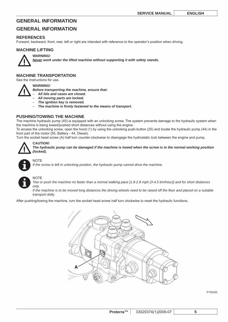
PUSHING/TOWING THE MACHINEThe machine hydraulic pump (45) is equipped with an unlocking screw. The system prevents damage to the hydraulic system when the machine is being towed/pushed short distances without using the engine.To access the unlocking screw, open the hood (1) by using the unlocking push-button (25) and locate the hydraulic pump (44) in the front part of the motor (55, Battery - 44, Diesel).Turn the socket head screw (A) half turn counter-clockwise to disengage the hydrostatic lock between the engine and pump.
CAUTION!The hydraulic pump can be damaged if the machine is towed when the screw is in the normal working position (locked).
NOTEIf the screw is left in unlocking position, the hydraulic pump cannot drive the machine.
NOTETow or push the machine no faster than a normal walking pace [1.8-2.8 mph (3-4.5 km/hour)] and for short distances only.If the machine is to be moved long distances the driving wheels need to be raised off the fl oor and placed on a suitable transport dolly.
After pushing/towing the machine, turn the socket head screw half turn clockwise to reset the hydraulic functions.
A
P100320
GENERAL INFORMATIONENGLISH SERVICE MANUAL
6 33020374(1)2009-07 Proterra™
ACCESSORIES/OPTIONSIn addition to the standard components, the machine can be equipped with the following accessories/equipment, according to the machine specifi c use:
Lead battery (WET) (for Battery version only) –Battery charger (for Battery version only) –Left side broom –Main and side brooms with harder or softer bristles –Polyester dust fi lter –Polyester closed pocket fi lter –Clogged fi lter sensor –Dust control system –Working light –Flashing light –Non-marking wheels –
Adjustable steering wheel –Driver’s seat with suspensions –Driver’s seat armrests –Safety belts –Side broom guard –Overhead guard –Fire extinguisher –Rearview mirrors –Rear bumper –Reverse gear buzzer –Hopper protection –Anti-skid mat –
OTHER AVAILABLE MANUALSThe following manuals are available at Advance Literature Service Department:
Proterra™ Diesel / LPG / Gasoline - Instructions for use – Advance Form Number 33019864 –Proterra™ Diesel / LPG / Gasoline - Spare Parts List – Advance Form Number 33019865 –Engine Manual – (supplied with the Instructions for use) –Proterra™ Battery - Instructions for use – Advance Form Number 33019867 –Proterra™ Battery - Spare Parts List – Advance Form Number 33019868 –12 V dust control system installation instructions – Advance Form Number 33018767 –48 V dust control system installation instructions – Advance Form Number 33019375 –Reverse gear buzzer installation instructions – Advance Form Number 33019168 –Left side broom installation instructions – Advance Form Number 33018767 –Rearview mirror installation instructions – Advance Form Number 33018767 –Closed pocket fi lter installation instructions – Advance Form Number 33018766 –Adjustable steering wheel installation instructions – Advance Form Number 33019157 –Safety belt installation instructions – Advance Form Number 33019209 –Right armrest installation instructions – Advance Form Number 33019211 –Anti-skid surface mirror installation instructions – Advance Form Number 33019195 –Rear protection installation instructions – Advance Form Number 33019205 –12 V front light system installation instructions – Advance Form Number 33019201 –48 V front light system installation instructions – Advance Form Number 33019561 –Hopper protection installation instructions – Advance Form Number 33019207 –
SAFETYThe following symbols indicate potentially dangerous situations. Always read this information carefully and take the necessary precautions to protect people and objects.
SYMBOLSDANGER!It indicates a dangerous situation with risk of death for the operator.
WARNING!It indicates a potential risk of injury for people or damage to objects.
CAUTION!It indicates a caution related to important or useful functions.Pay particular attention to the paragraphs marked by this symbol.
NOTEIt indicates a remark related to important or useful functions.
CONSULTATIONIt indicates the necessity to refer to the Instructions for use before performing any procedure.
GENERAL INFORMATIONSERVICE MANUAL ENGLISH
Proterra™ 33020374(1)2009-07 7
GENERAL INSTRUCTIONSSpecifi c warnings and cautions to inform about potential damages to people and machine are shown below.
DANGER![Battery / Diesel / LPG / Gasoline]
Before performing any maintenance, repair, cleaning or replacement procedure disconnect the battery –connector, remove the ignition key and engage the parking brake.This machine must be used by properly trained operators only. Children or disabled people cannot use this –machine.Sharp turns must be made at slowest possible speed. Avoid: abrupt turns on incline, turns when the hopper –is lifted. Do not lift the hopper when the machine is on incline. The machine loses stability on incline or when the –hopper is full. Do not wear jewels when working near electrical components. –Keep the battery away from sparks, fl ames and incandescent material. During the normal operation explosive –gases are released.Do not work under the lifted machine without supporting it with safety stands. –When working under open hoods, ensure that they cannot close by accident. –While performing maintenance or checks which require to pass/stop under the hopper, insert the hopper –safety support.Do not operate the machine near toxic, dangerous, infl ammable and/or explosive powders, liquids or vapors. –This machine is not suitable for collecting dangerous powders.(Equipped on Diesel / LPG / Gasoline, optional on Battery) When lead batteries (WET) are installed on this –machine, do not tilt the machine more than 30° from its horizontal position to prevent the highly corrosive acid to leak out of the batteries. When the machine is to be tilted to perform maintenance procedures, remove the batteries.
[Battery]If the machine is equipped with lead (WET) batteries, battery charging produces highly explosive hydrogen –gas. Keep the hood open when charging the batteries and perform this procedure in well-ventilated areas and away from naked fl ames.
[Diesel / LPG / Gasoline]Regularly check the tire pressure. –Be careful, fuel is highly fl ammable. –Do not smoke or bring naked fl ames in the area where the machine is refueled or where the fuel is stored. –Refuel outdoors or in a well-ventilated area, with the engine off. –Turn off the engine and let it cool down for a few minutes, then remove the fuel tank plug. –Leave at least a space of 1.6 in (4 cm) in the fi ller to allow the fuel to expand. –After refueling, check that the fi ller cap is tightly closed. –If any fuel is spilled while refueling, clean the tank area and allow the vapors to evaporate before starting the –engine.Avoid contact with skin and do not breathe in fuel vapors. Keep out of reach of children. –Do not tilt the engine too much to avoid fuel spillage. –When moving the machine, the fuel tank must not be full and the fuel tap must be closed. –Do not lay any object on the engine. –Stop the engine before performing any procedure on it. To prevent the engine from starting accidentally, –disconnect the battery negative terminal.See also the SAFETY RULES in the Engine Manual, which is to be considered an integral part of this Manual. –Do not use the machine in case of gas leaks. Disconnect the fuel hose and replace the LPG tank. If the gas –leak persists, disconnect the fuel hose and contact the Advance Service Center.
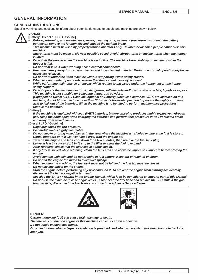
DANGER!Carbon monoxide (CO) can cause brain damage or death.The internal combustion engine of this machine can emit carbon monoxide.Do not inhale exhaust gas fumes.Only use indoors when adequate ventilation is provided, and when an assistant has been instructed to look after you.
GENERAL INFORMATIONENGLISH SERVICE MANUAL
8 33020374(1)2009-07 Proterra™
WARNING![Battery / Diesel / LPG / Gasoline]
Carefully read all the instructions before performing any maintenance/repair procedure. –When working on the machine always wear protective clothes and safety glasses. –Take all necessary precautions to prevent hair, jewels and loose clothes from being caught by the machine –moving parts.To avoid any unauthorized use of the machine, remove the ignition key. –Do not leave the machine unattended without being sure that it cannot move independently. –Do not use the machine on slopes with a gradient exceeding the specifi cations. –Use only brooms supplied with the machine and those specifi ed in the Instructions for use. Using other –brooms could reduce safety.Before using the machine, close all doors and/or covers. –Do not use the machine in particularly dusty areas. –Use the machine only where a proper lighting is provided. –If the machine is to be used where there are other people besides the operator, it is necessary to install the –pivoting light and the reverse gear buzzer (optional).Do not wash the machine with direct or pressurised water jets, or with corrosive substances. –Do not use compressed air to clean this type of machine, except for the fi lters (see the relevant paragraph). –While using this machine, take care not to cause damage to people and children especially. –Do not put any can containing fl uids on the machine. –The machine storage temperature must be 32°F to 104°F (0°C to +40°C). –The machine working temperature must be 32°F to 104°F (0°C to +40°C). –Humidity must be between 30% and 95%. –Always protect the machine against the sun, rain and bad weather, both under operation and inactivity –condition. Store the machine indoors, in a dry place. This machine must be used in dry conditions, it must not be used or kept outdoors in wet conditions.Do not use the machine as a means of transport, or for pushing/towing. –Do not allow the brushes to operate while the machine is stationary to avoid damaging the fl oor. –In case of fi re, use a powder fi re extinguisher, not a water one. –Do not bump into shelves or scaffoldings, particularly where there is a risk of falling objects. –Adjust the operation speed to suit the fl oor conditions. –Avoid sudden stops when the machine is going downhill. Avoid sharp turns. Drive at slow speed when going –downhill.This machine cannot be used on roads or public streets. –Do not tamper with the machine safety guards. –Follow the maintenance procedures scrupulously. –Do not remove or modify the plates affi xed to the machine. –In case of part replacement, order ORIGINAL spare parts from an authorized dealer or retailer. –The machine must be disposed of properly, because of the presence of toxic-harmful materials (batteries, –oil, plastics, etc.), which are subject to standards that require disposal in special centers (see Scrapping chapter).
[Battery]Do not smoke during battery charging. –
[Diesel / LPG / Gasoline]Pay attention to hot parts when working near the engine, the muffl er, the manifold and the cooler. –While the engine is running the silencer heats up. Do not touch the silencer to avoid serious scalding or fi re. –Do not run the engine if the oil level is low, to avoid damaging it seriously. Check the oil level with the engine –off and the machine on a level surface.Never run the engine if the air fi lter is not installed, because the engine could be damaged. –All diesel engine servicing procedures should be performed by an authorised Dealer. –Only use original spare parts or parts of matching quality for the diesel engine. Using spare parts of lower –quality can seriously damage the engine.See also the SAFETY RULES in the Engine Manual, which is to be considered an integral part of this Manual. –
GENERAL INFORMATIONSERVICE MANUAL ENGLISH
Proterra™ 33020374(1)2009-07 9
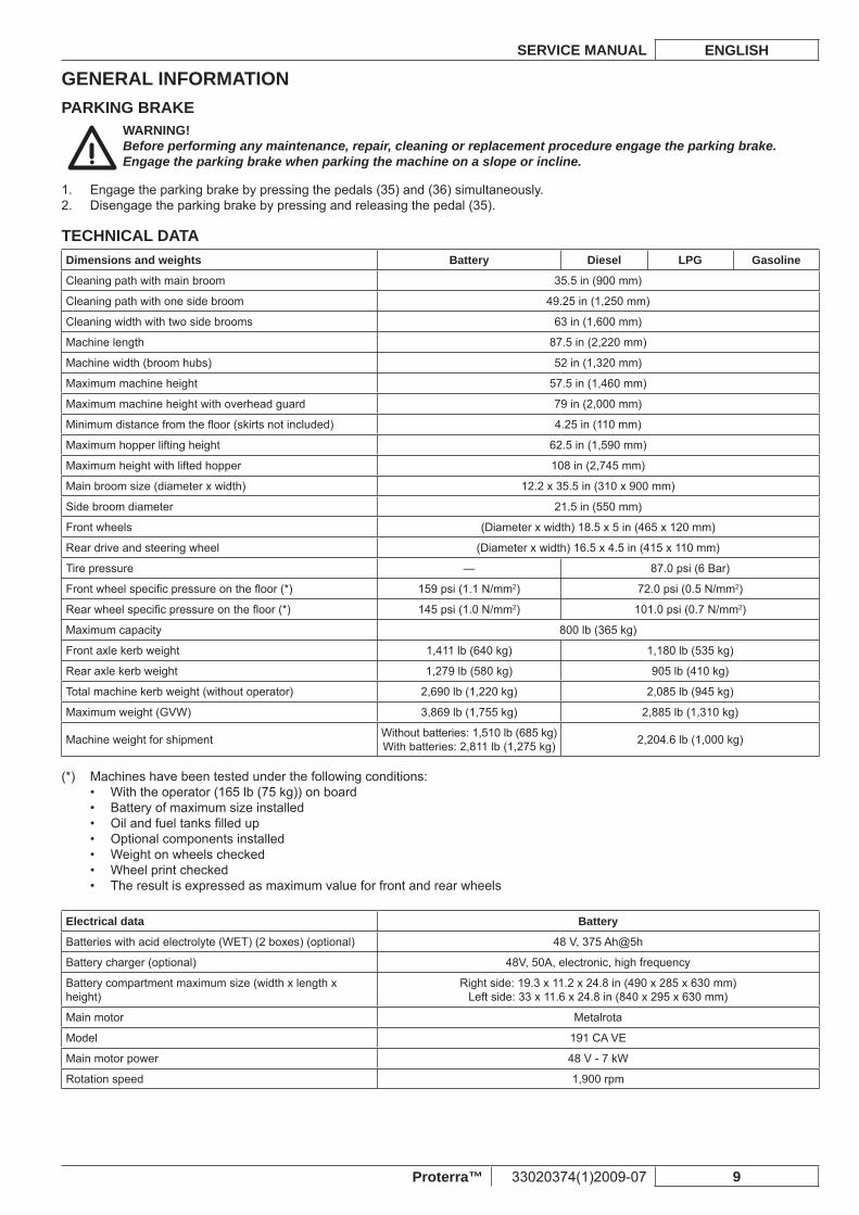
PARKING BRAKEWARNING!Before performing any maintenance, repair, cleaning or replacement procedure engage the parking brake.Engage the parking brake when parking the machine on a slope or incline.
Engage the parking brake by pressing the pedals (35) and (36) simultaneously.1. Disengage the parking brake by pressing and releasing the pedal (35).2.
TECHNICAL DATADimensions and weights Battery Diesel LPG Gasoline
Cleaning path with main broom 35.5 in (900 mm)
Cleaning path with one side broom 49.25 in (1,250 mm)
Cleaning width with two side brooms 63 in (1,600 mm)
Machine length 87.5 in (2,220 mm)
Machine width (broom hubs) 52 in (1,320 mm)
Maximum machine height 57.5 in (1,460 mm)
Maximum machine height with overhead guard 79 in (2,000 mm)
Minimum distance from the fl oor (skirts not included) 4.25 in (110 mm)
Maximum hopper lifting height 62.5 in (1,590 mm)
Maximum height with lifted hopper 108 in (2,745 mm)
Main broom size (diameter x width) 12.2 x 35.5 in (310 x 900 mm)
Side broom diameter 21.5 in (550 mm)
Front wheels (Diameter x width) 18.5 x 5 in (465 x 120 mm)
Rear drive and steering wheel (Diameter x width) 16.5 x 4.5 in (415 x 110 mm)
Tire pressure — 87.0 psi (6 Bar)
Front wheel specifi c pressure on the fl oor (*) 159 psi (1.1 N/mm2) 72.0 psi (0.5 N/mm2)
Rear wheel specifi c pressure on the fl oor (*) 145 psi (1.0 N/mm2) 101.0 psi (0.7 N/mm2)
Maximum capacity 800 lb (365 kg)
Front axle kerb weight 1,411 lb (640 kg) 1,180 lb (535 kg)
Rear axle kerb weight 1,279 lb (580 kg) 905 lb (410 kg)
Total machine kerb weight (without operator) 2,690 lb (1,220 kg) 2,085 lb (945 kg)
Maximum weight (GVW) 3,869 lb (1,755 kg) 2,885 lb (1,310 kg)
Machine weight for shipment Without batteries: 1,510 lb (685 kg)With batteries: 2,811 lb (1,275 kg) 2,204.6 lb (1,000 kg)
Machines have been tested under the following conditions:(*) With the operator (165 lb (75 kg)) on board• Battery of maximum size installed• Oil and fuel tanks fi lled up• Optional components installed• Weight on wheels checked• Wheel print checked• The result is expressed as maximum value for front and rear wheels•
Electrical data Battery
Batteries with acid electrolyte (WET) (2 boxes) (optional) 48 V, 375 Ah@5h
Battery charger (optional) 48V, 50A, electronic, high frequency
Battery compartment maximum size (width x length x height)
Right side: 19.3 x 11.2 x 24.8 in (490 x 285 x 630 mm)Left side: 33 x 11.6 x 24.8 in (840 x 295 x 630 mm)
Main motor Metalrota
Model 191 CA VE
Main motor power 48 V - 7 kW
Rotation speed 1,900 rpm
GENERAL INFORMATIONENGLISH SERVICE MANUAL
10 33020374(1)2009-07 Proterra™
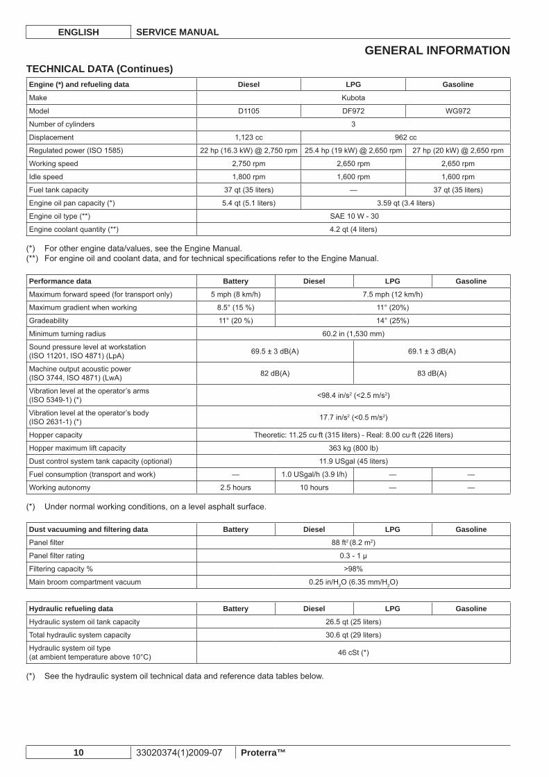
TECHNICAL DATA (Continues)Engine (*) and refueling data Diesel LPG Gasoline
Make Kubota
Model D1105 DF972 WG972
Number of cylinders 3
Displacement 1,123 cc 962 cc
Regulated power (ISO 1585) 22 hp (16.3 kW) @ 2,750 rpm 25.4 hp (19 kW) @ 2,650 rpm 27 hp (20 kW) @ 2,650 rpm
Working speed 2,750 rpm 2,650 rpm 2,650 rpm
Idle speed 1,800 rpm 1,600 rpm 1,600 rpm
Fuel tank capacity 37 qt (35 liters) — 37 qt (35 liters)
Engine oil pan capacity (*) 5.4 qt (5.1 liters) 3.59 qt (3.4 liters)
Engine oil type (**) SAE 10 W - 30
Engine coolant quantity (**) 4.2 qt (4 liters)
For other engine data/values, see the Engine Manual.(*) For engine oil and coolant data, and for technical specifi cations refer to the Engine Manual.(**)
Performance data Battery Diesel LPG Gasoline
Maximum forward speed (for transport only) 5 mph (8 km/h) 7.5 mph (12 km/h)
Maximum gradient when working 8.5° (15 %) 11° (20%)
Gradeability 11° (20 %) 14° (25%)
Minimum turning radius 60.2 in (1,530 mm)
Sound pressure level at workstation(ISO 11201, ISO 4871) (LpA) 69.5 ± 3 dB(A) 69.1 ± 3 dB(A)
Machine output acoustic power(ISO 3744, ISO 4871) (LwA) 82 dB(A) 83 dB(A)
Vibration level at the operator’s arms(ISO 5349-1) (*) <98.4 in/s2 (<2.5 m/s2)
Vibration level at the operator’s body(ISO 2631-1) (*) 17.7 in/s2 (<0.5 m/s2)
Hopper capacity Theoretic: 11.25 cu·ft (315 liters) - Real: 8.00 cu·ft (226 liters)
Hopper maximum lift capacity 363 kg (800 lb)
Dust control system tank capacity (optional) 11.9 USgal (45 liters)
Fuel consumption (transport and work) — 1.0 USgal/h (3.9 l/h) — —
Working autonomy 2.5 hours 10 hours — —
Under normal working conditions, on a level asphalt surface.(*)
Dust vacuuming and fi ltering data Battery Diesel LPG Gasoline
Panel fi lter 88 ft2 (8.2 m2)
Panel fi lter rating 0.3 - 1 μ
Filtering capacity % >98%
Main broom compartment vacuum 0.25 in/H2O (6.35 mm/H2O)
Hydraulic refueling data Battery Diesel LPG Gasoline
Hydraulic system oil tank capacity 26.5 qt (25 liters)
Total hydraulic system capacity 30.6 qt (29 liters)
Hydraulic system oil type (at ambient temperature above 10°C) 46 cSt (*)
See the hydraulic system oil technical data and reference data tables below.(*)
GENERAL INFORMATIONSERVICE MANUAL ENGLISH
Proterra™ 33020374(1)2009-07 11
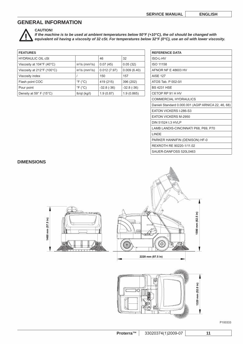
CAUTION!If the machine is to be used at ambient temperatures below 50°F (+10°C), the oil should be changed with equivalent oil having a viscosity of 32 cSt. For temperatures below 32°F (0°C), use an oil with lower viscosity.
FEATURES REFERENCE DATA
HYDRAULIC OIL cSt 46 32 ISO-L-HV
Viscosity at 104°F (40°C) in2/s (mm2/s) 0.07 (45) 0.05 (32) ISO 11158
Viscosity at 212°F (100°C) in2/s (mm2/s) 0.012 (7.97) 0.009 (6.40) AFNOR NF E 48603 HV
Viscosity index / 150 157 AISE 127
Flash point COC °F (°C) 419 (215) 396 (202) ATOS Tab. P 002-0/I
Pour point °F (°C) -32.8 (-36) -32.8 (-36) BS 4231 HSE
Density at 59° F (15°C) lb/qt (kg/l) 1.9 (0.87) 1.9 (0.865) CETOP RP 91 H HV
COMMERCIAL HYDRAULICS
Danieli Standard 0.000.001 (AGIP ARNICA 22, 46, 68)
EATON VICKERS I-286-S3
EATON VICKERS M-2950
DIN 51524 t.3 HVLP
LAMB LANDIS-CINCINNATI P68, P69, P70
LINDE
PARKER HANNIFIN (DENISON) HF-0
REXROTH RE 90220-1/11.02
SAUER-DANFOSS 520L0463
DIMENSIONS
1320
mm
(52.
0 in
)
1460
mm
(57.
5 in
)
1590
mm
(62.
5 in
)
2220 mm (87.5 in)
P100333
GENERAL INFORMATIONENGLISH SERVICE MANUAL
12 33020374(1)2009-07 Proterra™
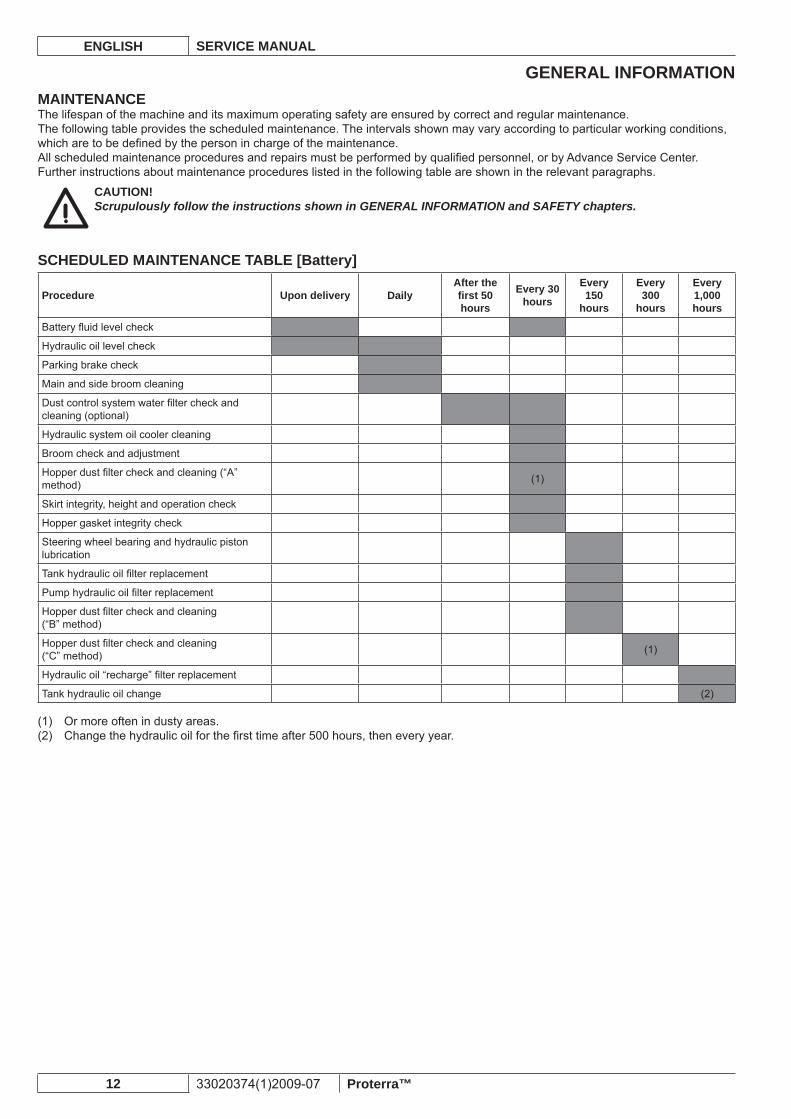
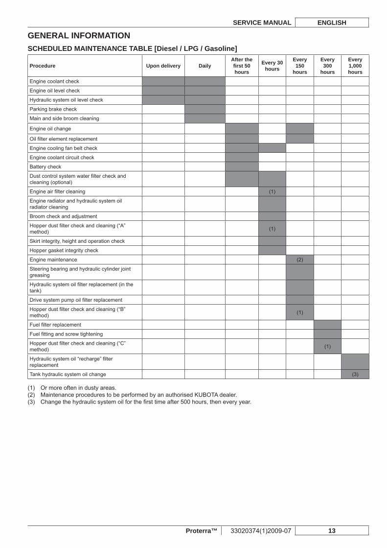
MAINTENANCEThe lifespan of the machine and its maximum operating safety are ensured by correct and regular maintenance.The following table provides the scheduled maintenance. The intervals shown may vary according to particular working conditions, which are to be defi ned by the person in charge of the maintenance.All scheduled maintenance procedures and repairs must be performed by qualifi ed personnel, or by Advance Service Center.Further instructions about maintenance procedures listed in the following table are shown in the relevant paragraphs.
CAUTION!Scrupulously follow the instructions shown in GENERAL INFORMATION and SAFETY chapters.
SCHEDULED MAINTENANCE TABLE [Battery]
Procedure Upon delivery DailyAfter the fi rst 50 hours
Every 30 hours
Every 150
hours
Every 300
hours
Every 1,000 hours
Battery fl uid level check
Hydraulic oil level check
Parking brake check
Main and side broom cleaning
Dust control system water fi lter check and cleaning (optional)
Hydraulic system oil cooler cleaning
Broom check and adjustment
Hopper dust fi lter check and cleaning (“A” method) (1)
Skirt integrity, height and operation check
Hopper gasket integrity check
Steering wheel bearing and hydraulic piston lubrication
Tank hydraulic oil fi lter replacement
Pump hydraulic oil fi lter replacement
Hopper dust fi lter check and cleaning(“B” method)
Hopper dust fi lter check and cleaning(“C” method) (1)
Hydraulic oil “recharge” fi lter replacement
Tank hydraulic oil change (2)
Or more often in dusty areas.(1) Change the hydraulic oil for the fi rst time after 500 hours, then every year.(2)
GENERAL INFORMATIONSERVICE MANUAL ENGLISH
Proterra™ 33020374(1)2009-07 13
SCHEDULED MAINTENANCE TABLE [Diesel / LPG / Gasoline]
Procedure Upon delivery DailyAfter the fi rst 50 hours
Every 30 hours
Every 150
hours
Every 300
hours
Every 1,000 hours
Engine coolant check
Engine oil level check
Hydraulic system oil level check
Parking brake check
Main and side broom cleaning
Engine oil change
Oil fi lter element replacement
Engine cooling fan belt check
Engine coolant circuit check
Battery check
Dust control system water fi lter check and cleaning (optional)
Engine air fi lter cleaning (1)
Engine radiator and hydraulic system oil radiator cleaning
Broom check and adjustment
Hopper dust fi lter check and cleaning (“A” method) (1)
Skirt integrity, height and operation check
Hopper gasket integrity check
Engine maintenance (2)
Steering bearing and hydraulic cylinder joint greasing
Hydraulic system oil fi lter replacement (in the tank)
Drive system pump oil fi lter replacement
Hopper dust fi lter check and cleaning (“B” method) (1)
Fuel fi lter replacement
Fuel fi tting and screw tightening
Hopper dust fi lter check and cleaning (“C” method) (1)
Hydraulic system oil “recharge” fi lter replacement
Tank hydraulic system oil change (3)
Or more often in dusty areas.(1) Maintenance procedures to be performed by an authorised KUBOTA dealer.(2) Change the hydraulic system oil for the fi rst time after 500 hours, then every year.(3)
GENERAL INFORMATIONENGLISH SERVICE MANUAL
14 33020374(1)2009-07 Proterra™
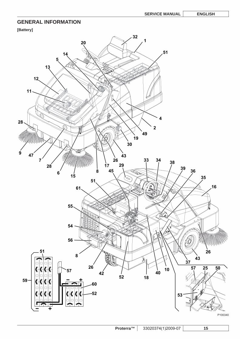
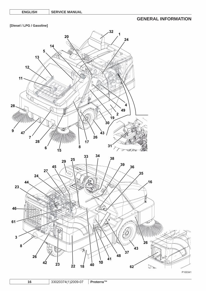
MACHINE NOMENCLATUREThroughout this Manual you will fi nd numbers in brackets – for example: (2). These numbers refer to the components indicated in these two nomenclature pages. Refer to these pages whenever it is necessary to identify a component mentioned in the text.
MACHINE NOMENCLATURE
Rear hood1. Left side main broom access panel2. [3. *D-G-P] BatteryLeft side hood, or dust guard system water tank (optional)4. Hopper safety support5. Hopper hood latch6. Working light (optional)7. Jacking locations (rear location is under the left battery box 8. or the engine radiator)Right side broom9. Serial number plate/technical data/conformity certifi cation10. Dust fi lter shaker assembly11. Hopper dust fi lter12. Panel fi lter (standard)Closed pocket fi lter (optional)Filter shaker assembly mounting knobs13. Drive system pump oil fi lter14. Left side broom (optional)15. Front hood16. Front hood support rod17. Right side main broom access panel18. Hydraulic system oil tank19. Hydraulic system oil tank plug20. [21. *D-P] Fuel tank plug[22. *D-P] Fuel tank[23. *D-G-P] Radiator plug[24. *D-G-P] Engine air fi lterRear hood release push-button25. Tie-down locations (3)26. [27. *D-G-P] Air fi lter service indicatorDust guard system nozzles (optional)28. Dust guard system water tank plug (optional)29. Water fi lter (optional)30.
[31. *D-G-P] Engine model and serial number plateDriver’s seat32. Control panel (see the following paragraph)33. Steering wheel34. Service brake pedal35. Parking brake pedal36. (To engage/disengage the parking brake, use simultaneously with the service brake pedal)Forward/reverse gear pedal37. Circuit breaker panel38. Hopper safety support handle39.
Pull backward to lock the support (*)• Push forward to unlock the support (*)•
Driver’s seat adjustment lever40. [41. *D-G-P] Engine air gridRear drive and steering wheel42. Front wheels43. [44. *D-G-P] EngineHydraulic pump45. [46. *D-G-P] Engine coolant/hydraulic oil radiatorHopper47. [48. *D-G-P] FusesHydraulic system oil level indicator49. [50. *B] Battery connector quick release control: This connector also works as EMERGENCY push-button to stop immediately all machine functions[51. *B] Left side batteries[52. *B] Right side batteries[53. *B] Fuse box cover (see the Fuse Check/Replacement/Reset paragraph)[54. *B] Hydraulic system oil cooler fan[55. *B] Main hydraulic pump motor[56. *B] Hydraulic system oil cooler[57. *B] Battery connector[58. *B] Driver’s seat adjustment lever[59. *B] Battery connection diagram[60. *B] Battery caps (for WET batteries only)Fire extinguisher (optional)61. [62. *G] LPG cylinder
[*B] Equipped on Battery version[*D] Equipped on Diesel version[*G] Equipped on LPG version[*P] Equipped on Gasoline version
GENERAL INFORMATIONSERVICE MANUAL ENGLISH
Proterra™ 33020374(1)2009-07 15
[Battery]
9
28
477
286
1551
4529
33 34
39 3635
16
3743
26
57 25 50
53
1840
1052
4226
8
56
54
55
61
51
57
60
52
59
38
817
2643
3019
492
4
321
51
20
145
13
12
11
P100340
GENERAL INFORMATIONENGLISH SERVICE MANUAL
16 33020374(1)2009-07 Proterra™
[Diesel / LPG / Gasoline]
9 477
286 15
2945
2724
4423
61
46
3
8
2642 23 22 18 40
4148
3743
26
16
3635
393825
33 34
817
2643
3019
249
4
24132
20
145
13
12
11
31
28
1062
P100341
GENERAL INFORMATIONSERVICE MANUAL ENGLISH
Proterra™ 33020374(1)2009-07 17
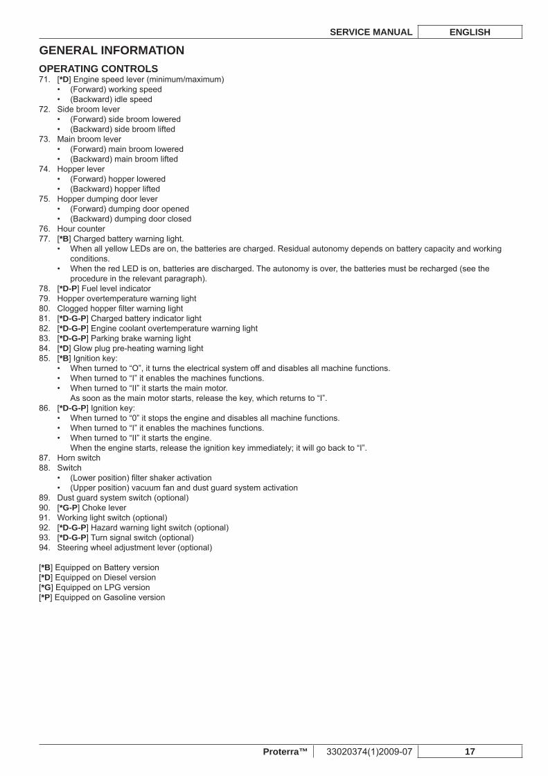
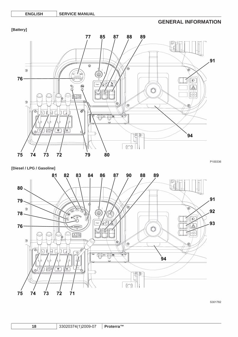
OPERATING CONTROLS[71. *D] Engine speed lever (minimum/maximum)
(Forward) working speed• (Backward) idle speed•
Side broom lever72. (Forward) side broom lowered• (Backward) side broom lifted•
Main broom lever73. (Forward) main broom lowered• (Backward) main broom lifted•
Hopper lever74. (Forward) hopper lowered• (Backward) hopper lifted•
Hopper dumping door lever75. (Forward) dumping door opened• (Backward) dumping door closed•
Hour counter76. [77. *B] Charged battery warning light.
When all yellow LEDs are on, the batteries are charged. Residual autonomy depends on battery capacity and working • conditions.When the red LED is on, batteries are discharged. The autonomy is over, the batteries must be recharged (see the • procedure in the relevant paragraph).
[78. *D-P] Fuel level indicatorHopper overtemperature warning light79. Clogged hopper fi lter warning light80. [81. *D-G-P] Charged battery indicator light[82. *D-G-P] Engine coolant overtemperature warning light[83. *D-G-P] Parking brake warning light[84. *D] Glow plug pre-heating warning light[85. *B] Ignition key:
When turned to “O”, it turns the electrical system off and disables all machine functions.• When turned to “I” it enables the machines functions.• When turned to “II” it starts the main motor.• As soon as the main motor starts, release the key, which returns to “I”.
[86. *D-G-P] Ignition key:When turned to “0” it stops the engine and disables all machine functions.• When turned to “I” it enables the machines functions.• When turned to “II” it starts the engine.• When the engine starts, release the ignition key immediately; it will go back to “I”.
Horn switch87. Switch88.
(Lower position) fi lter shaker activation• (Upper position) vacuum fan and dust guard system activation•
Dust guard system switch (optional)89. [90. *G-P] Choke lever Working light switch (optional)91. [92. *D-G-P] Hazard warning light switch (optional)[93. *D-G-P] Turn signal switch (optional)Steering wheel adjustment lever (optional)94.
[*B] Equipped on Battery version[*D] Equipped on Diesel version[*G] Equipped on LPG version[*P] Equipped on Gasoline version
GENERAL INFORMATIONENGLISH SERVICE MANUAL
18 33020374(1)2009-07 Proterra™
[Battery]
72 79 80737475
76
8577 87 88 89
91
94
P100336
[Diesel / LPG / Gasoline]
7172737475
76
78
79
80
81 82 83 84 86 87 8890 89
91
92
93
94
S301782
SWEEPING SYSTEMSERVICE MANUAL ENGLISH
Proterra™ 33020374(1)2009-07 19
SWEEPING SYSTEMTROUBLESHOOTING [All versions]Poor operation or excessive wear of the side and main broomsPossible cause:
The broom height is not properly adjusted (adjust).1.
The side or main broom lowers even when the relevant control is not activatedPossible causes
The check valve is faulty (replace).1.
The side or main broom does not turnPossible cause:
Debris wrapped around the broom drive (clean the broom).1. The hopper is not fully lowered (lower the hopper).2. There are oil leaks from hoses (replace gaskets/hoses).3. The distributor is faulty (repair or replace).4. The broom motor is faulty (repair or replace).5. The accessory pump does not pressurize the oil in the circuit (check the hydraulic system oil pressure).6.
The brooms do not lift/lowerPossible cause:
There are oil leaks from hoses (replace gaskets/hoses).1. The distributor is faulty (repair or replace).2. The lifting/lowering hydraulic cylinder gaskets are worn (check the cylinder).3. The accessory pump does not pressurize the oil in the circuit (check the hydraulic system oil pressure).4.
SWEEPING SYSTEMENGLISH SERVICE MANUAL
20 33020374(1)2009-07 Proterra™
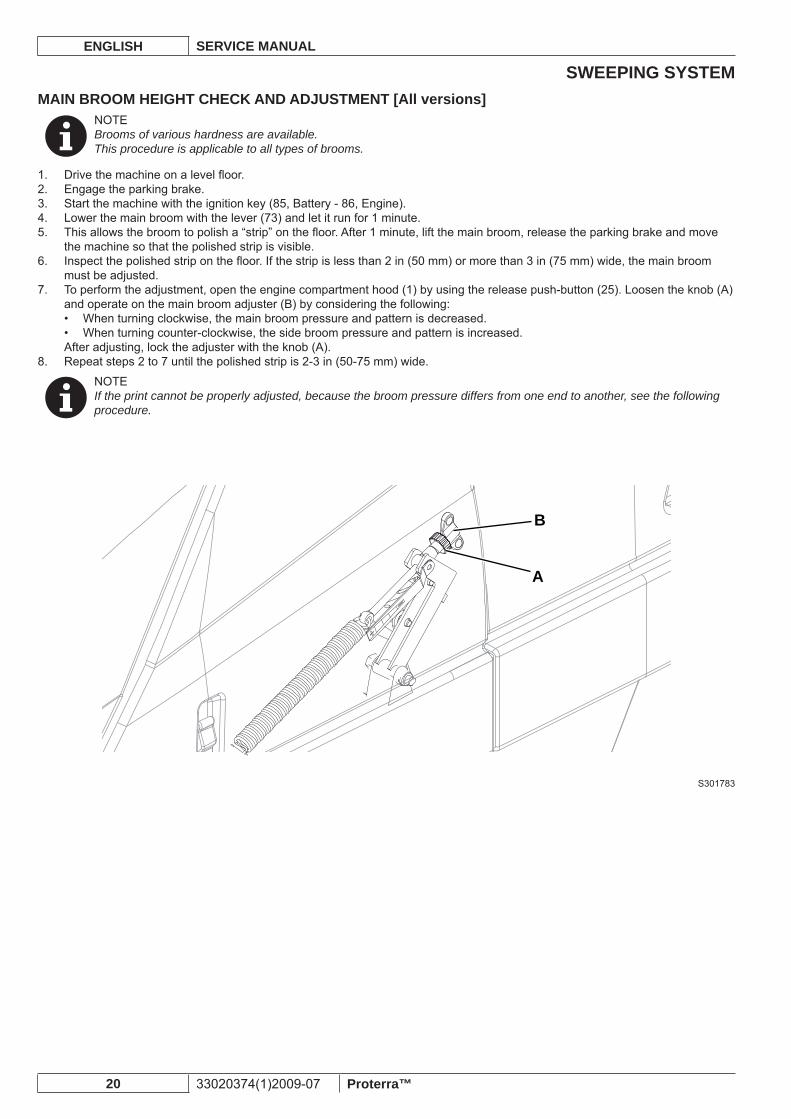
MAIN BROOM HEIGHT CHECK AND ADJUSTMENT [All versions]NOTEBrooms of various hardness are available.This procedure is applicable to all types of brooms.
Drive the machine on a level fl oor.1. Engage the parking brake.2. Start the machine with the ignition key (85, Battery - 86, Engine).3. Lower the main broom with the lever (73) and let it run for 1 minute.4. This allows the broom to polish a “strip” on the fl oor. After 1 minute, lift the main broom, release the parking brake and move 5. the machine so that the polished strip is visible.Inspect the polished strip on the fl oor. If the strip is less than 2 in (50 mm) or more than 3 in (75 mm) wide, the main broom 6. must be adjusted.To perform the adjustment, open the engine compartment hood (1) by using the release push-button (25). Loosen the knob (A) 7. and operate on the main broom adjuster (B) by considering the following:
When turning clockwise, the main broom pressure and pattern is decreased.• When turning counter-clockwise, the side broom pressure and pattern is increased.•
After adjusting, lock the adjuster with the knob (A).Repeat steps 2 to 7 until the polished strip is 2-3 in (50-75 mm) wide.8.
NOTEIf the print cannot be properly adjusted, because the broom pressure differs from one end to another, see the following procedure.
B
A
S301783
SWEEPING SYSTEMSERVICE MANUAL ENGLISH
Proterra™ 33020374(1)2009-07 21
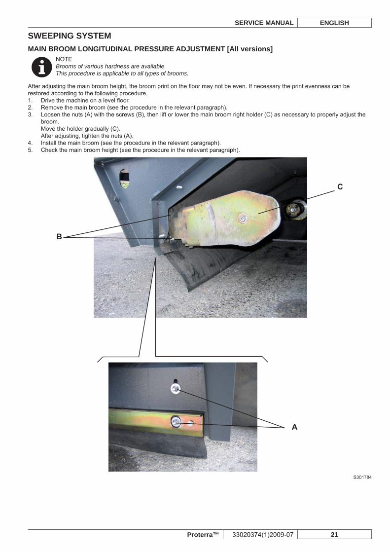
MAIN BROOM LONGITUDINAL PRESSURE ADJUSTMENT [All versions]NOTEBrooms of various hardness are available.This procedure is applicable to all types of brooms.
After adjusting the main broom height, the broom print on the fl oor may not be even. If necessary the print evenness can be restored according to the following procedure.
Drive the machine on a level fl oor.1. Remove the main broom (see the procedure in the relevant paragraph).2. Loosen the nuts (A) with the screws (B), then lift or lower the main broom right holder (C) as necessary to properly adjust the 3. broom.Move the holder gradually (C).After adjusting, tighten the nuts (A).Install the main broom (see the procedure in the relevant paragraph).4. Check the main broom height (see the procedure in the relevant paragraph).5.
D
S301784
SWEEPING SYSTEMENGLISH SERVICE MANUAL
22 33020374(1)2009-07 Proterra™
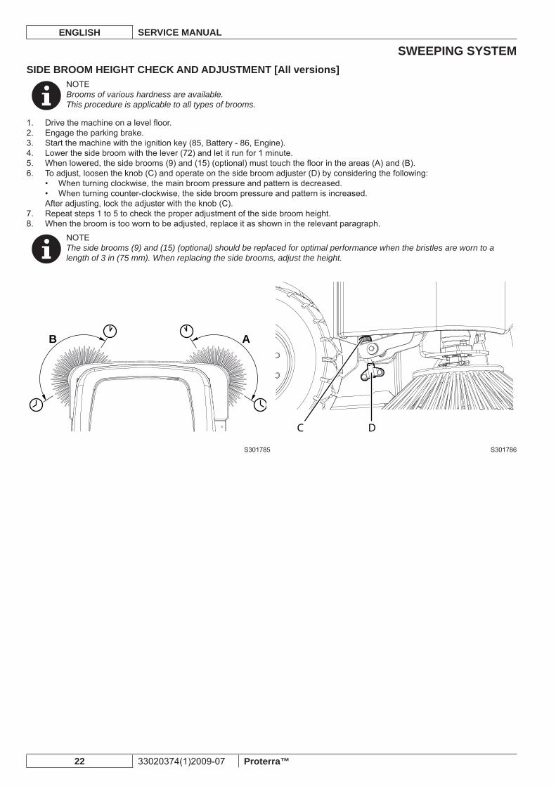
SIDE BROOM HEIGHT CHECK AND ADJUSTMENT [All versions]NOTEBrooms of various hardness are available.This procedure is applicable to all types of brooms.
Drive the machine on a level fl oor.1. Engage the parking brake.2. Start the machine with the ignition key (85, Battery - 86, Engine).3. Lower the side broom with the lever (72) and let it run for 1 minute.4. When lowered, the side brooms (9) and (15) (optional) must touch the fl oor in the areas (A) and (B).5. To adjust, loosen the knob (C) and operate on the side broom adjuster (D) by considering the following:6.
When turning clockwise, the main broom pressure and pattern is decreased.• When turning counter-clockwise, the side broom pressure and pattern is increased.•
After adjusting, lock the adjuster with the knob (C).Repeat steps 1 to 5 to check the proper adjustment of the side broom height.7. When the broom is too worn to be adjusted, replace it as shown in the relevant paragraph.8.
NOTEThe side brooms (9) and (15) (optional) should be replaced for optimal performance when the bristles are worn to a length of 3 in (75 mm). When replacing the side brooms, adjust the height.
AB
DC
S301785 S301786
SWEEPING SYSTEMSERVICE MANUAL ENGLISH
Proterra™ 33020374(1)2009-07 23
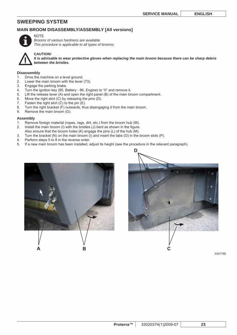
MAIN BROOM DISASSEMBLY/ASSEMBLY [All versions]NOTEBrooms of various hardness are available.This procedure is applicable to all types of brooms.
CAUTION!It is advisable to wear protective gloves when replacing the main broom because there can be sharp debris between the bristles.
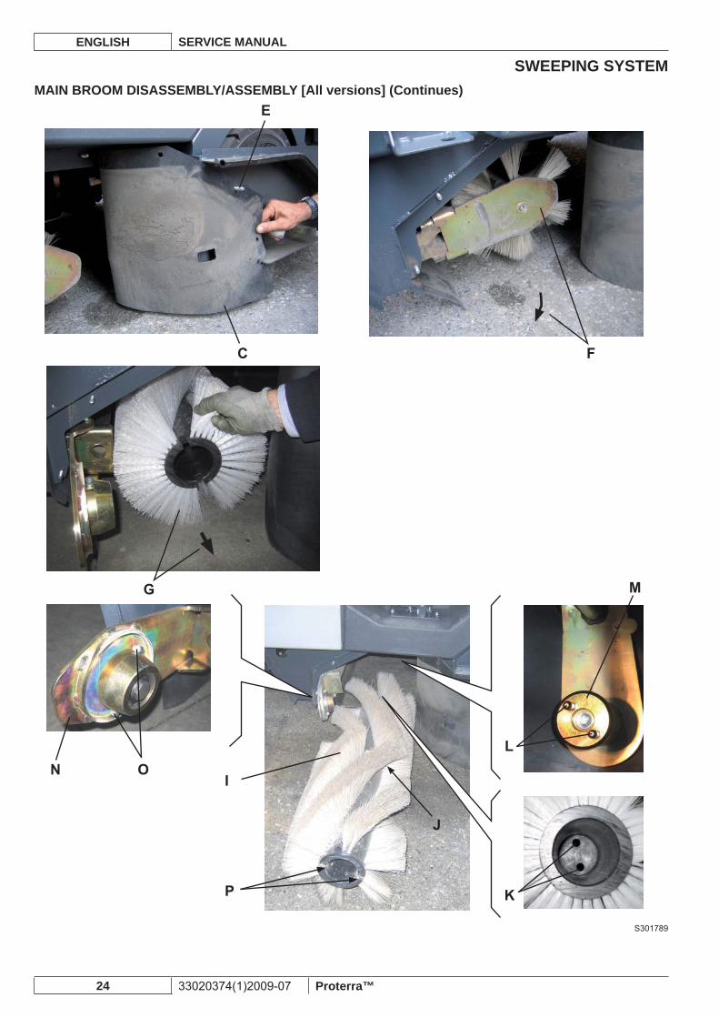
DisassemblyDrive the machine on a level ground.1. Lower the main broom with the lever (73).2. Engage the parking brake.3. Turn the ignition key (85, Battery - 86, Engine) to “0” and remove it.4. Lift the release lever (A) and open the right panel (B) of the main broom compartment.5. Move the right skirt (C) by releasing the pins (D).6. Fasten the right skirt (C) to the pin (E).7. Turn the right bracket (F) outwards, thus disengaging it from the main broom.8. Remove the main broom (G).9.
AssemblyRemove foreign material (ropes, rags, dirt, etc.) from the broom hub (M).1. Install the main broom (I) with the bristles (J) bent as shown in the fi gure.2. Also ensure that the broom holes (K) engage the pins (L) of the hub (M).Turn the bracket (N) on the main broom (I) and insert the tabs (O) in the broom slots (P).3. Perform steps 5 to 8 in the reverse order.4. If a new main broom has been installed, adjust its height (see the procedure in the relevant paragraph).5.
S301788
SWEEPING SYSTEMENGLISH SERVICE MANUAL
24 33020374(1)2009-07 Proterra™
MAIN BROOM DISASSEMBLY/ASSEMBLY [All versions] (Continues)
S301789
SWEEPING SYSTEMSERVICE MANUAL ENGLISH
Proterra™ 33020374(1)2009-07 25
SIDE BROOM DISASSEMBLY/ASSEMBLY [All versions]Where this symbol is shown, proceed according to the Instructions for use.(*)
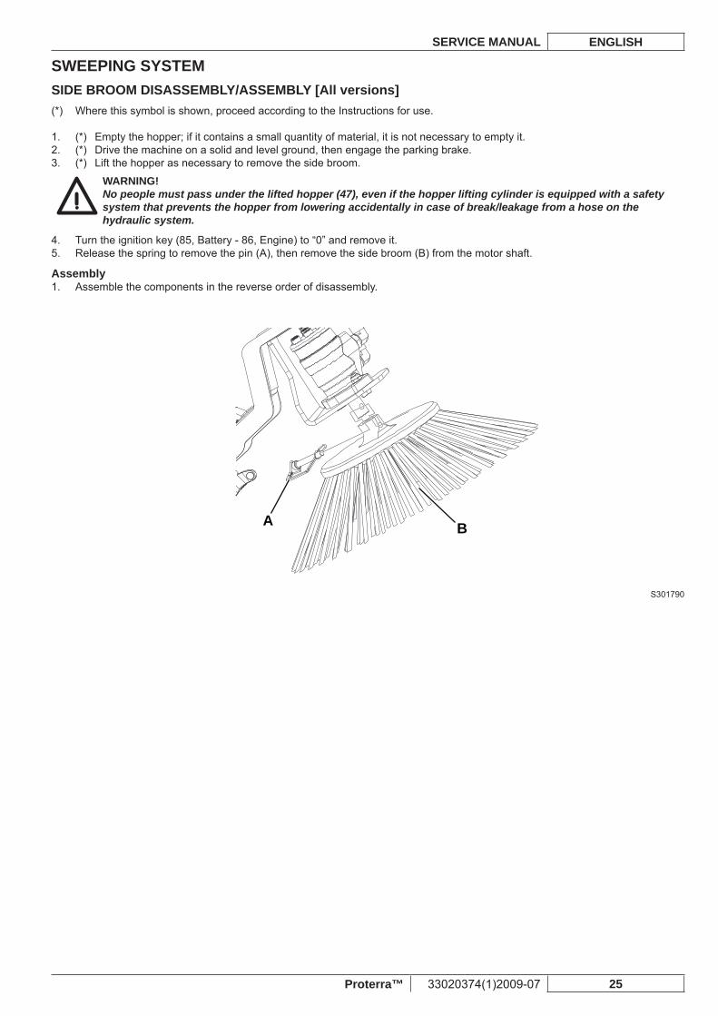
(*) Empty the hopper; if it contains a small quantity of material, it is not necessary to empty it.1. (*) Drive the machine on a solid and level ground, then engage the parking brake.2. (*) Lift the hopper as necessary to remove the side broom.3.
WARNING!No people must pass under the lifted hopper (47), even if the hopper lifting cylinder is equipped with a safety system that prevents the hopper from lowering accidentally in case of break/leakage from a hose on the hydraulic system.
Turn the ignition key (85, Battery - 86, Engine) to “0” and remove it.4. Release the spring to remove the pin (A), then remove the side broom (B) from the motor shaft.5.
AssemblyAssemble the components in the reverse order of disassembly.1.
A B
S301790
SWEEPING SYSTEMENGLISH SERVICE MANUAL
26 33020374(1)2009-07 Proterra™
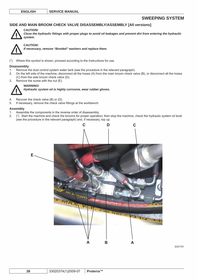
SIDE AND MAIN BROOM CHECK VALVE DISASSEMBLY/ASSEMBLY [All versions]CAUTION!Close the hydraulic fi ttings with proper plugs to avoid oil leakages and prevent dirt from entering the hydraulic system.
CAUTION!If necessary, remove “Bonded” washers and replace them.
Where this symbol is shown, proceed according to the Instructions for use.(*)
DisassemblyRemove the dust control system water tank (see the procedure in the relevant paragraph).1. On the left side of the machine, disconnect all the hoses (A) from the main broom check valve (B), or disconnect all the hoses 2. (C) from the side broom check valve (D).Remove the screw with the nut (E).3.
WARNING!Hydraulic system oil is highly corrosive, wear rubber gloves.
Recover the check valve (B) or (D).4. If necessary, remove the check valve fi ttings at the workbench.5.
AssemblyAssemble the components in the reverse order of disassembly.1. (*) Start the machine and check the brooms for proper operation; then stop the machine, check the hydraulic system oil level 2. (see the procedure in the relevant paragraph) and, if necessary, top up.
S301791
SWEEPING SYSTEMSERVICE MANUAL ENGLISH
Proterra™ 33020374(1)2009-07 27
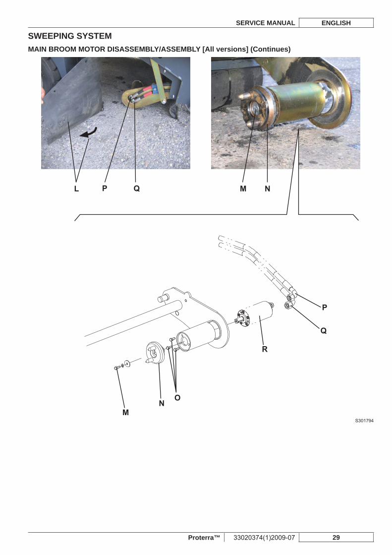
MAIN BROOM MOTOR DISASSEMBLY/ASSEMBLY [All versions]CAUTION!Close the hydraulic fi ttings with proper plugs to avoid oil leakages and prevent dirt from entering the hydraulic system.
Where this symbol is shown, proceed according to the Instructions for use.(*)
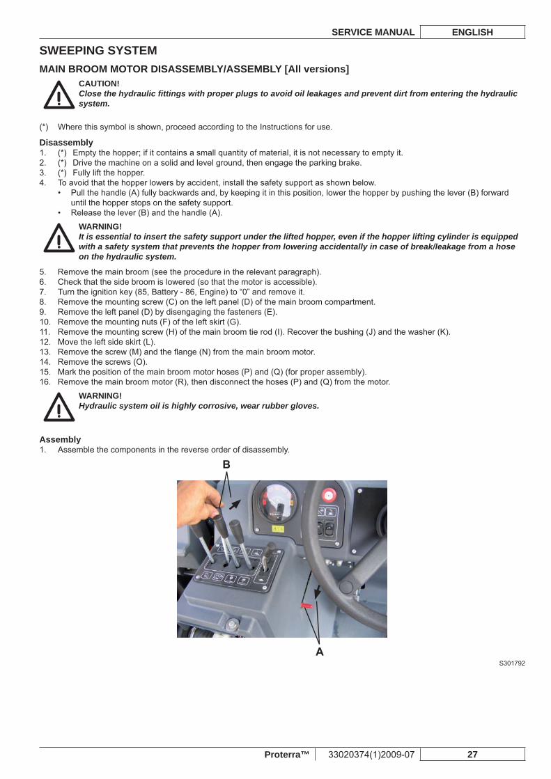
Disassembly(*) Empty the hopper; if it contains a small quantity of material, it is not necessary to empty it.1. (*) Drive the machine on a solid and level ground, then engage the parking brake.2. (*) Fully lift the hopper.3. To avoid that the hopper lowers by accident, install the safety support as shown below.4.
Pull the handle (A) fully backwards and, by keeping it in this position, lower the hopper by pushing the lever (B) forward • until the hopper stops on the safety support.Release the lever (B) and the handle (A).•
WARNING!It is essential to insert the safety support under the lifted hopper, even if the hopper lifting cylinder is equipped with a safety system that prevents the hopper from lowering accidentally in case of break/leakage from a hose on the hydraulic system.
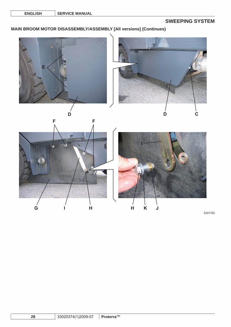
Remove the main broom (see the procedure in the relevant paragraph).5. Check that the side broom is lowered (so that the motor is accessible).6. Turn the ignition key (85, Battery - 86, Engine) to “0” and remove it.7. Remove the mounting screw (C) on the left panel (D) of the main broom compartment.8. Remove the left panel (D) by disengaging the fasteners (E).9. Remove the mounting nuts (F) of the left skirt (G).10. Remove the mounting screw (H) of the main broom tie rod (I). Recover the bushing (J) and the washer (K).11. Move the left side skirt (L).12. Remove the screw (M) and the fl ange (N) from the main broom motor.13. Remove the screws (O).14. Mark the position of the main broom motor hoses (P) and (Q) (for proper assembly).15. Remove the main broom motor (R), then disconnect the hoses (P) and (Q) from the motor.16.
WARNING!Hydraulic system oil is highly corrosive, wear rubber gloves.
AssemblyAssemble the components in the reverse order of disassembly.1.
S301792
SWEEPING SYSTEMENGLISH SERVICE MANUAL
28 33020374(1)2009-07 Proterra™
MAIN BROOM MOTOR DISASSEMBLY/ASSEMBLY [All versions] (Continues)
S301793
SWEEPING SYSTEMSERVICE MANUAL ENGLISH
Proterra™ 33020374(1)2009-07 29
MAIN BROOM MOTOR DISASSEMBLY/ASSEMBLY [All versions] (Continues)
S301794
SWEEPING SYSTEMENGLISH SERVICE MANUAL
30 33020374(1)2009-07 Proterra™
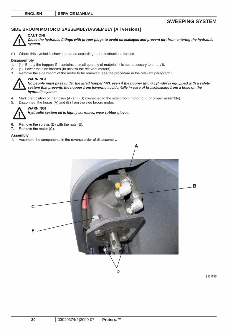
SIDE BROOM MOTOR DISASSEMBLY/ASSEMBLY [All versions]CAUTION!Close the hydraulic fi ttings with proper plugs to avoid oil leakages and prevent dirt from entering the hydraulic system.
Where this symbol is shown, proceed according to the Instructions for use.(*)
Disassembly(*) Empty the hopper; if it contains a small quantity of material, it is not necessary to empty it.1. (*) Lower the side brooms (to access the relevant motors).2. Remove the side broom of the motor to be removed (see the procedure in the relevant paragraph).3.
WARNING!No people must pass under the lifted hopper (47), even if the hopper lifting cylinder is equipped with a safety system that prevents the hopper from lowering accidentally in case of break/leakage from a hose on the hydraulic system.
Mark the position of the hoses (A) and (B) connected to the side broom motor (C) (for proper assembly).4. Disconnect the hoses (A) and (B) from the side broom motor.5.
WARNING!Hydraulic system oil is highly corrosive, wear rubber gloves.
Remove the screws (D) with the nuts (E).6. Remove the motor (C).7.
AssemblyAssemble the components in the reverse order of disassembly.1.
S301795
SWEEPING SYSTEMSERVICE MANUAL ENGLISH
Proterra™ 33020374(1)2009-07 31
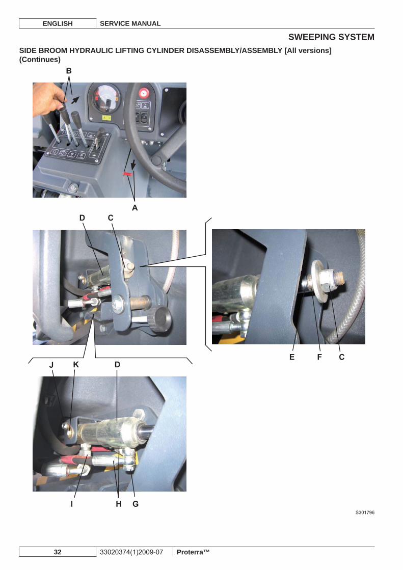
SIDE BROOM HYDRAULIC LIFTING CYLINDER DISASSEMBLY/ASSEMBLY [All versions]CAUTION!Close the hydraulic fi ttings with proper plugs to avoid oil leakages and prevent dirt from entering the hydraulic system.
CAUTION!If necessary, remove “Bonded” washers and replace them.
Where this symbol is shown, proceed according to the Instructions for use.(*)
Disassembly(*) Empty the hopper; if it contains a small quantity of material, it is not necessary to empty it.1. (*) Drive the machine on a solid and level ground, then engage the parking brake.2. (*) Fully lift the hopper.3. To avoid that the hopper lowers by accident, install the safety support as shown below.4.
Pull the handle (A) fully backwards and, by keeping it in this position, lower the hopper by pushing the lever (B) forward • until the hopper stops on the safety support.Release the lever (B) and the handle (A).•
WARNING!It is essential to insert the safety support under the lifted hopper, even if the hopper lifting cylinder is equipped with a safety system that prevents the hopper from lowering accidentally in case of break/leakage from a hose on the hydraulic system.
Lower the side brooms.5. Turn the ignition key (85, Battery - 86, Engine) to “0” and remove it.6. Remove the side broom of the hydraulic cylinder to be removed (see the procedure in the relevant paragraph).7. Unscrew the nut (C) of the side broom hydraulic lifting cylinder (D) by holding the rod (E) at the position (F).8. If the hydraulic cylinder (D) is locked and the rod (E) cannot be extracted to reach the position (F), remove the hoses before unscrewing the nut (C), as shown in steps 9 and 10.Remove the screw (G) and disconnect the hoses (H) from the hydraulic cylinder (D).9.
WARNING!Hydraulic system oil is highly corrosive, wear rubber gloves.
Unscrew the hose fi tting (I) from the hydraulic cylinder (D).10. Remove the screw (J) and the fl ange with the pin (K).11. Remove the side broom hydraulic lifting cylinder (D).12.
AssemblyAssemble the components in the reverse order of disassembly.1. (*) Start the machine and check the side brooms for proper lifting/lowering operation; then stop the machine, check the 2. hydraulic system oil level (see the procedure in the relevant paragraph) and, if necessary, top up.
SWEEPING SYSTEMENGLISH SERVICE MANUAL
32 33020374(1)2009-07 Proterra™
SIDE BROOM HYDRAULIC LIFTING CYLINDER DISASSEMBLY/ASSEMBLY [All versions] (Continues)
S301796
SWEEPING SYSTEMSERVICE MANUAL ENGLISH
Proterra™ 33020374(1)2009-07 33
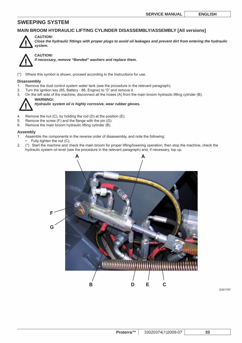
MAIN BROOM HYDRAULIC LIFTING CYLINDER DISASSEMBLY/ASSEMBLY [All versions]CAUTION!Close the hydraulic fi ttings with proper plugs to avoid oil leakages and prevent dirt from entering the hydraulic system.
CAUTION!If necessary, remove “Bonded” washers and replace them.
Where this symbol is shown, proceed according to the Instructions for use.(*)
DisassemblyRemove the dust control system water tank (see the procedure in the relevant paragraph).1. Turn the ignition key (85, Battery - 86, Engine) to “0” and remove it.2. On the left side of the machine, disconnect all the hoses (A) from the main broom hydraulic lifting cylinder (B).3.
WARNING!Hydraulic system oil is highly corrosive, wear rubber gloves.
Remove the nut (C), by holding the rod (D) at the position (E).4. Remove the screw (F) and the fl ange with the pin (G).5. Remove the main broom hydraulic lifting cylinder (B).6.
AssemblyAssemble the components in the reverse order of disassembly, and note the following:1.
Fully tighten the nut (C).• (*) Start the machine and check the main broom for proper lifting/lowering operation; then stop the machine, check the 2. hydraulic system oil level (see the procedure in the relevant paragraph) and, if necessary, top up.
S301797

SWEEPING SYSTEMENGLISH SERVICE MANUAL
34 33020374(1)2009-07 Proterra™
SKIRTSERVICE MANUAL ENGLISH
Proterra™ 33020374(1)2009-07 35
SKIRTSKIRT HEIGHT AND OPERATION CHECK [All versions]
Where this symbol is shown, proceed according to the Instructions for use.(*)
Preliminary operations(*) Empty the hopper.1. (*) Drive the machine on a level ground and engage the parking brake.2. Turn the ignition key (85, Battery - 86, Engine) to “0” and remove it.3.
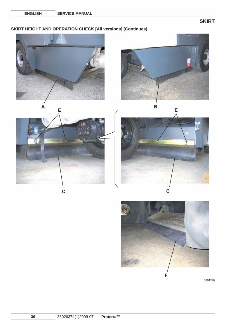
Side skirtsCheck the side skirts (A) and (B) for integrity. Replace the side skirts when cut or torn/broken (see the procedure in the 1. relevant paragraph), otherwise the machine vacuum capabilities can be affected.Check that the side skirts (A) and (B) are fl ush with the fl oor, or that the distance from the fl oor is not higher than 0.25 in (6 2. mm), otherwise replace them (see the procedure in the relevant paragraph).
Rear skirtCheck the rear skirt (C) for integrity. Replace the rear skirt when cut or torn/broken (see the procedure in the relevant 1. paragraph), otherwise the machine vacuum capabilities can be affected.Check that the rear skirt (C) is fl ush with the fl oor, or that the distance from the fl oor is not higher than 0.25 in (6 mm), otherwise adjust it as shown below:
Loosen the mounting screws (E) of the rear skirt.• By using the slots of the mounting holes, adjust the rear skirt (C) so that the distance from the fl oor is not higher than 0.2 in • (6 mm), then tighten the screws (E).
If the rear skirt cannot be adjusted, replace it (see the procedure in the relevant paragraph).
Front skirtRemove the main broom (see the procedure in the relevant paragraph).1. (*) Check that the hopper is fully lowered.2. (*) Fully open the hopper dumping door.3. Turn the ignition key (85, Battery - 86, Engine) to “0” and remove it.4. Check the front skirt (F) for integrity by looking through the main broom compartment. Replace the front skirt when cut or torn/5. broken (see the procedure in the relevant paragraph), otherwise the machine vacuum capabilities can be affected.Check that the front skirt (F) leans on the fl oor as shown in the fi gure; if it is detached from the fl oor proceed as follows:
If the front skirt (F) is not worn, adjust its height (see the procedure in Hopper Closure Check and Adjustment paragraph).• If the front skirt (F) is too worn, replace it (see the procedure in the relevant paragraph).•
ResetAssemble the components in the reverse order of disassembly.1.
SKIRTENGLISH SERVICE MANUAL
36 33020374(1)2009-07 Proterra™
SKIRT HEIGHT AND OPERATION CHECK [All versions] (Continues)
S301798
SKIRTSERVICE MANUAL ENGLISH
Proterra™ 33020374(1)2009-07 37
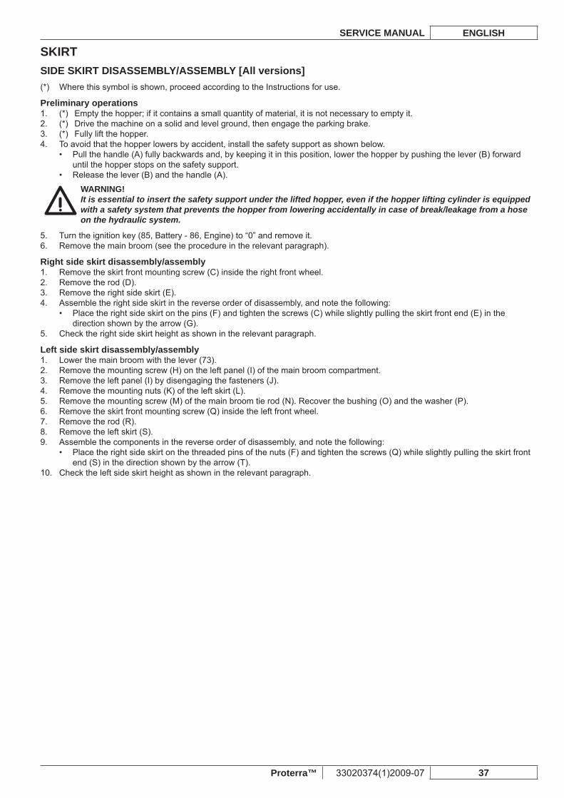
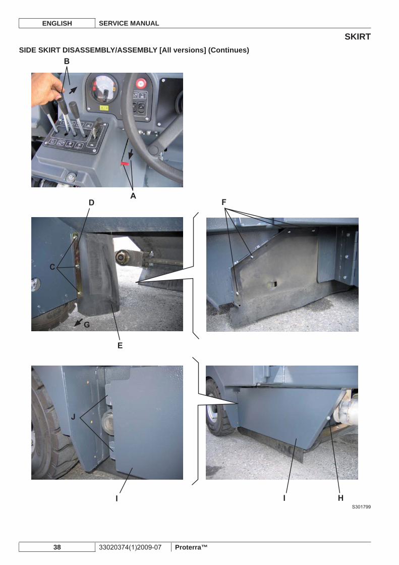
SIDE SKIRT DISASSEMBLY/ASSEMBLY [All versions]Where this symbol is shown, proceed according to the Instructions for use.(*)
Preliminary operations(*) Empty the hopper; if it contains a small quantity of material, it is not necessary to empty it.1. (*) Drive the machine on a solid and level ground, then engage the parking brake.2. (*) Fully lift the hopper.3. To avoid that the hopper lowers by accident, install the safety support as shown below.4.
Pull the handle (A) fully backwards and, by keeping it in this position, lower the hopper by pushing the lever (B) forward • until the hopper stops on the safety support.Release the lever (B) and the handle (A).•
WARNING!It is essential to insert the safety support under the lifted hopper, even if the hopper lifting cylinder is equipped with a safety system that prevents the hopper from lowering accidentally in case of break/leakage from a hose on the hydraulic system.
Turn the ignition key (85, Battery - 86, Engine) to “0” and remove it.5. Remove the main broom (see the procedure in the relevant paragraph).6.
Right side skirt disassembly/assemblyRemove the skirt front mounting screw (C) inside the right front wheel.1. Remove the rod (D).2. Remove the right side skirt (E).3. Assemble the right side skirt in the reverse order of disassembly, and note the following:4.
Place the right side skirt on the pins (F) and tighten the screws (C) while slightly pulling the skirt front end (E) in the • direction shown by the arrow (G).
Check the right side skirt height as shown in the relevant paragraph.5.
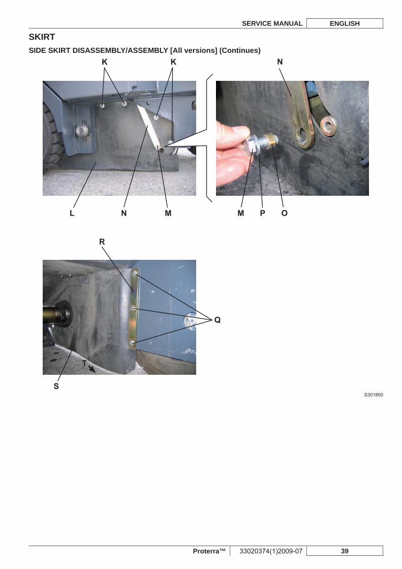
Left side skirt disassembly/assemblyLower the main broom with the lever (73).1. Remove the mounting screw (H) on the left panel (I) of the main broom compartment.2. Remove the left panel (I) by disengaging the fasteners (J).3. Remove the mounting nuts (K) of the left skirt (L).4. Remove the mounting screw (M) of the main broom tie rod (N). Recover the bushing (O) and the washer (P).5. Remove the skirt front mounting screw (Q) inside the left front wheel.6. Remove the rod (R).7. Remove the left skirt (S).8. Assemble the components in the reverse order of disassembly, and note the following:9.
Place the right side skirt on the threaded pins of the nuts (F) and tighten the screws (Q) while slightly pulling the skirt front • end (S) in the direction shown by the arrow (T).
Check the left side skirt height as shown in the relevant paragraph.10.
SKIRTENGLISH SERVICE MANUAL
38 33020374(1)2009-07 Proterra™
SIDE SKIRT DISASSEMBLY/ASSEMBLY [All versions] (Continues)
S301799
SKIRTSERVICE MANUAL ENGLISH
Proterra™ 33020374(1)2009-07 39
SIDE SKIRT DISASSEMBLY/ASSEMBLY [All versions] (Continues)
S301800
SKIRTENGLISH SERVICE MANUAL
40 33020374(1)2009-07 Proterra™
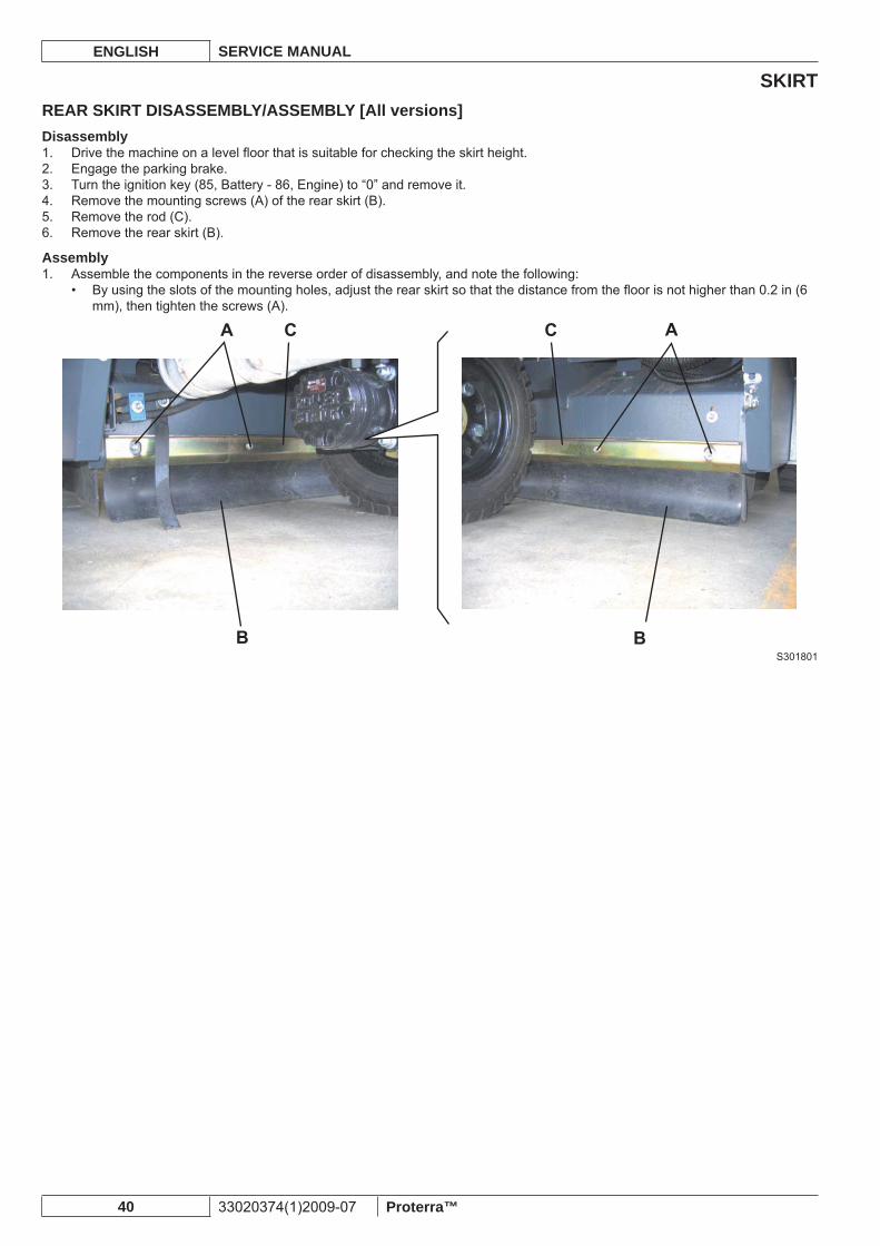
REAR SKIRT DISASSEMBLY/ASSEMBLY [All versions]Disassembly
Drive the machine on a level fl oor that is suitable for checking the skirt height.1. Engage the parking brake.2. Turn the ignition key (85, Battery - 86, Engine) to “0” and remove it.3. Remove the mounting screws (A) of the rear skirt (B).4. Remove the rod (C).5. Remove the rear skirt (B).6.
AssemblyAssemble the components in the reverse order of disassembly, and note the following:1.
By using the slots of the mounting holes, adjust the rear skirt so that the distance from the fl oor is not higher than 0.2 in (6 • mm), then tighten the screws (A).
S301801
SKIRTSERVICE MANUAL ENGLISH
Proterra™ 33020374(1)2009-07 41
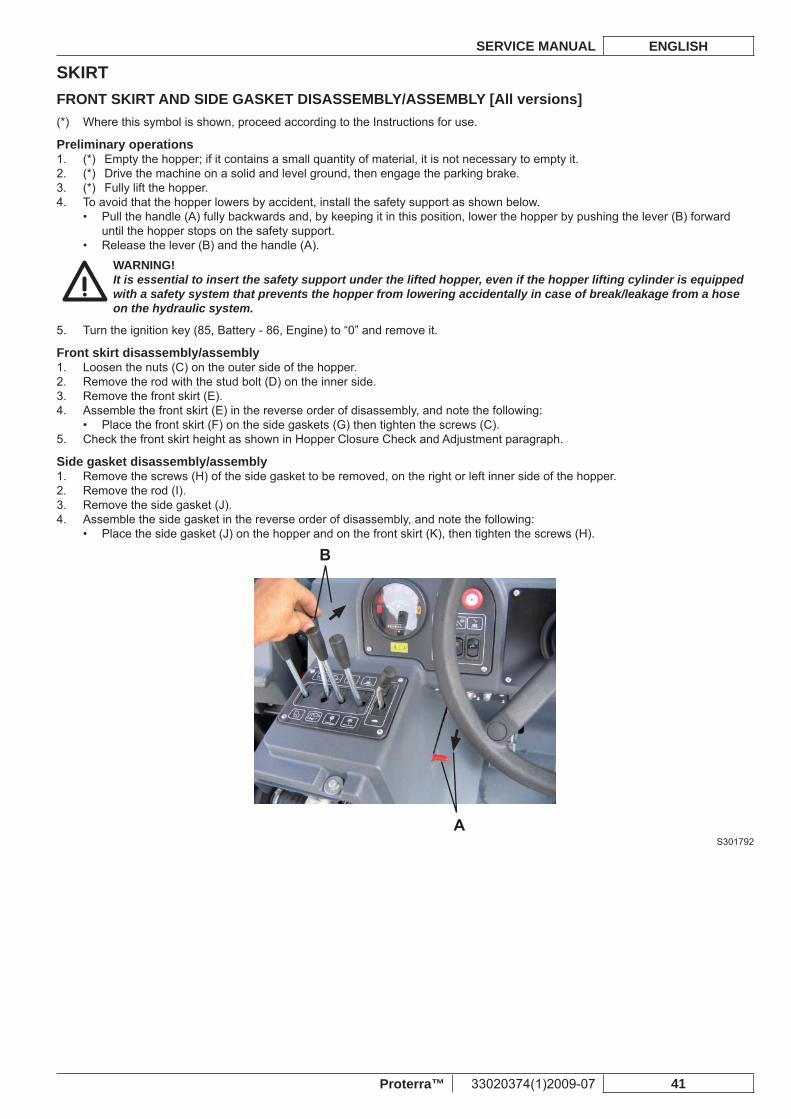
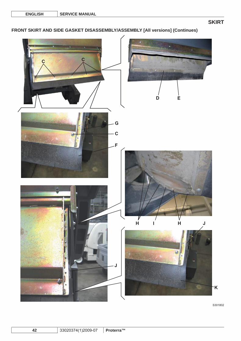
FRONT SKIRT AND SIDE GASKET DISASSEMBLY/ASSEMBLY [All versions]Where this symbol is shown, proceed according to the Instructions for use.(*)
Preliminary operations(*) Empty the hopper; if it contains a small quantity of material, it is not necessary to empty it.1. (*) Drive the machine on a solid and level ground, then engage the parking brake.2. (*) Fully lift the hopper.3. To avoid that the hopper lowers by accident, install the safety support as shown below.4.
Pull the handle (A) fully backwards and, by keeping it in this position, lower the hopper by pushing the lever (B) forward • until the hopper stops on the safety support.Release the lever (B) and the handle (A).•
WARNING!It is essential to insert the safety support under the lifted hopper, even if the hopper lifting cylinder is equipped with a safety system that prevents the hopper from lowering accidentally in case of break/leakage from a hose on the hydraulic system.
Turn the ignition key (85, Battery - 86, Engine) to “0” and remove it.5.
Front skirt disassembly/assemblyLoosen the nuts (C) on the outer side of the hopper.1. Remove the rod with the stud bolt (D) on the inner side.2. Remove the front skirt (E).3. Assemble the front skirt (E) in the reverse order of disassembly, and note the following:4.
Place the front skirt (F) on the side gaskets (G) then tighten the screws (C).• Check the front skirt height as shown in Hopper Closure Check and Adjustment paragraph.5.
Side gasket disassembly/assemblyRemove the screws (H) of the side gasket to be removed, on the right or left inner side of the hopper.1. Remove the rod (I).2. Remove the side gasket (J).3. Assemble the side gasket in the reverse order of disassembly, and note the following:4.
Place the side gasket (J) on the hopper and on the front skirt (K), then tighten the screws (H).•
S301792
SKIRTENGLISH SERVICE MANUAL
42 33020374(1)2009-07 Proterra™
FRONT SKIRT AND SIDE GASKET DISASSEMBLY/ASSEMBLY [All versions] (Continues)
S301802
DUST AND DEBRIS COLLECTION SYSTEMSERVICE MANUAL ENGLISH
Proterra™ 33020374(1)2009-07 43
DUST AND DEBRIS COLLECTION SYSTEMTROUBLESHOOTING [All versions]The machine collects little dustPossible causes
The vacuum system is turned off (turn on).1. The hopper is full (empty it).2. The skirts are not integral or not properly adjusted (replace/adjust).3. The main broom height is not correct (adjust).4. The dust fi lter is clogged (clean).5. The fi lter shaker is faulty (replace the fi lter shaker motor).6. The vacuum fan fi ns are broken/worn (replace the vacuum fan assembly).7. The vacuum fan motor is faulty (check the motor/replace the vacuum fan assembly).8. The thermal fuse is deactivated (reset the fuse).9.
The fi lter shaker motor does not workPossible causes
The fi lter shaker motor connector is not properly connected (connect).1. The motor is faulty (repair or replace).2. The fi lter shaker push-button is broken (replace).3. The wiring harness is damaged (repair).4. The thermal fuse is deactivated (reset the fuse).5.
The hopper door does not close properlyPossible causes
The door is stuck by debris (clean).1. The door is not properly adjusted (adjust).2. The hydraulic cylinder is faulty (repair or replace).3.
DUST AND DEBRIS COLLECTION SYSTEMENGLISH SERVICE MANUAL
44 33020374(1)2009-07 Proterra™
FILTER SHAKER OPERATION CHECK [All versions]Drive the machine and start sweeping as shown in the Instructions for use.1. Then empty the hopper. When the hopper has been dumped, turn on the fi lter shaker and check that more dust comes out by effect of the fi lter shaker activation. Check for fi lter shaker operation noise.
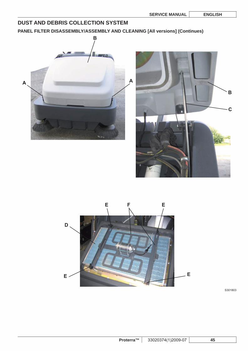
PANEL FILTER DISASSEMBLY/ASSEMBLY AND CLEANING [All versions]The hopper panel fi lter must be cleaned regularly to maintain the effi ciency of the vacuum system. Follow the recommended fi lter service intervals for the longest fi lter life.
WARNING!Wear safety glasses when cleaning the fi lter. –Do not puncture the fi lter. –Clean the fi lter in a well-ventilated area. –Wear appropriate dust mask to avoid breathing in dust. –
Drive the machine on a level fl oor, engage the parking brake and turn the ignition key (85, Battery - 86, Engine) to “0” and 1. remove it.Open the latches (A) and lift the front hood (B) then hold it with the support rod (C).2. Check the dust fi lter upper part (D) for damage. A large amount of dust on top of the fi lter is usually caused by a hole in the 3. fi lter or a damaged fi lter gasket.Unscrew the fi lter shaker assembly mounting knobs (E). Lift the fi lter shaker assembly (F) to access the fi lter (D).4. Lift the fi lter (D) and remove it from the machine.5. Clean the fi lter (D) by using one of the following methods:6.
Method “A”Vacuum loose dust from the fi lter. Then gently tap the fi lter against a fl at surface (with the dirty side down) to remove loose dust and dirt.
NOTETake care not to damage the metal lip which extends past the gasket.
Method “B”Vacuum loose dust from the fi lter. Then blow compressed air (maximum pressure 87.0 psi (6 Bar)) into the clean side of the fi lter (in the opposite direction of the airfl ow).
Method “C”Vacuum loose dust from the fi lter. Then soak the fi lter in warm water for 15 minutes, then rinse it under a gentle stream of water (maximum pressure 36.0 psi (2.5 Bar)). Let the fi lter dry completely before installing it back into the machine.
NOTEFor proper drying, lay the fi lter horizontally on two spacers to allow the air to fl ow under the fi lter.
NOTEFor a better cleaning, it is allowed to wash the fi lter with water and non-lathering detergents.This provides better quality cleaning but reduces the life of the fi lter, which will have to be replaced more frequently. Using inadequate detergents can damage the fi lter.
Assemble the fi lter in the reverse order of disassembly, and note the following:7. Install the fi lter with the wire gauze up.• If the fi lter gasket is damaged or missing, it must be replaced.•
NOTEBefore installing the fi lter, clear debris from dust plate located under fi lter.Check that the debris skirt at the rear of the dust plate swings freely.
DUST AND DEBRIS COLLECTION SYSTEMSERVICE MANUAL ENGLISH
Proterra™ 33020374(1)2009-07 45
PANEL FILTER DISASSEMBLY/ASSEMBLY AND CLEANING [All versions] (Continues)
S301803
DUST AND DEBRIS COLLECTION SYSTEMENGLISH SERVICE MANUAL
46 33020374(1)2009-07 Proterra™
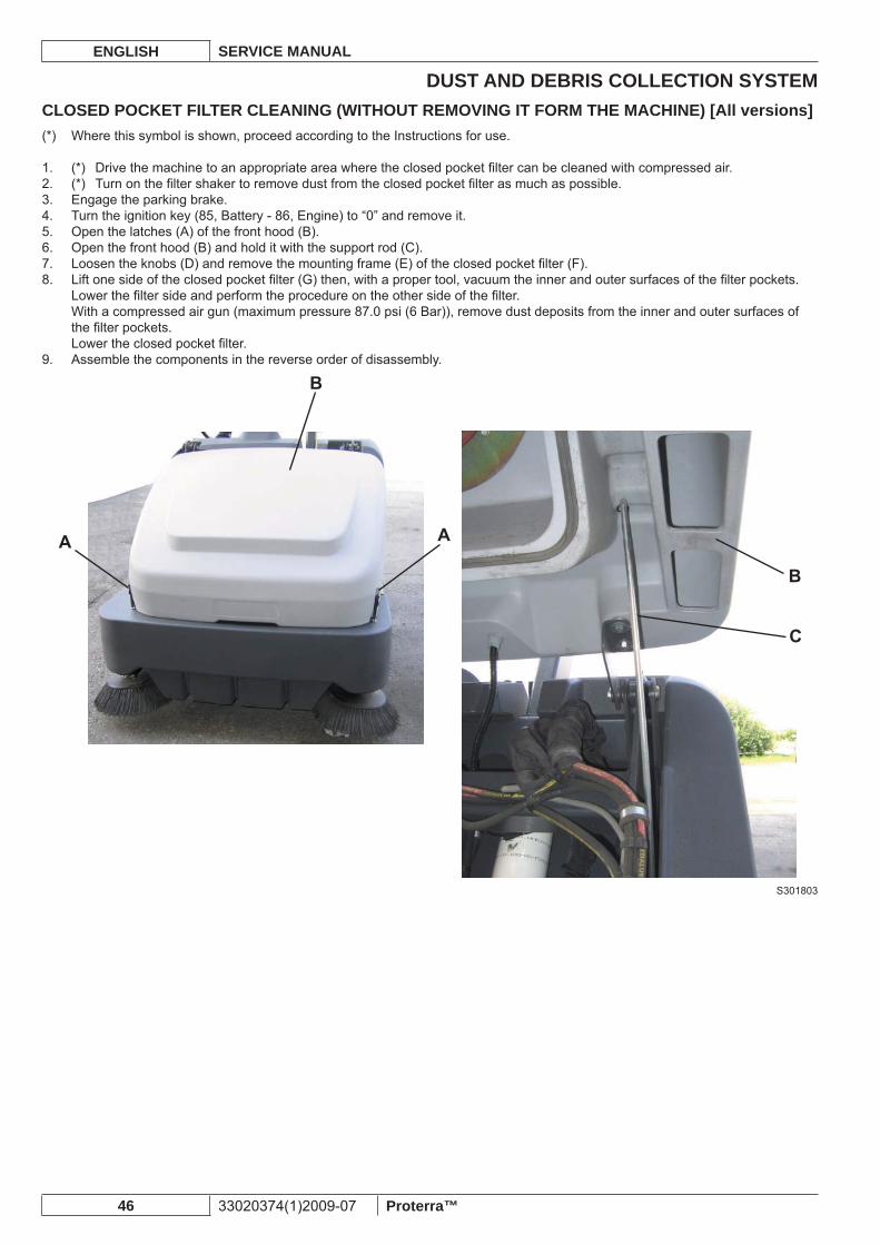
CLOSED POCKET FILTER CLEANING (WITHOUT REMOVING IT FORM THE MACHINE) [All versions]Where this symbol is shown, proceed according to the Instructions for use.(*)
(*) Drive the machine to an appropriate area where the closed pocket fi lter can be cleaned with compressed air.1. (*) Turn on the fi lter shaker to remove dust from the closed pocket fi lter as much as possible.2. Engage the parking brake.3. Turn the ignition key (85, Battery - 86, Engine) to “0” and remove it.4. Open the latches (A) of the front hood (B).5. Open the front hood (B) and hold it with the support rod (C).6. Loosen the knobs (D) and remove the mounting frame (E) of the closed pocket fi lter (F).7. Lift one side of the closed pocket fi lter (G) then, with a proper tool, vacuum the inner and outer surfaces of the fi lter pockets.8. Lower the fi lter side and perform the procedure on the other side of the fi lter.With a compressed air gun (maximum pressure 87.0 psi (6 Bar)), remove dust deposits from the inner and outer surfaces of the fi lter pockets.Lower the closed pocket fi lter.Assemble the components in the reverse order of disassembly.9.
S301803
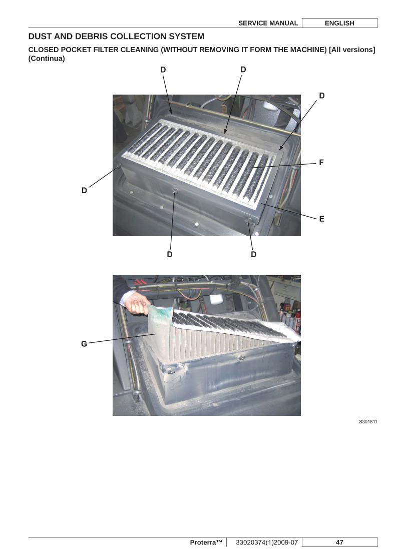
DUST AND DEBRIS COLLECTION SYSTEMSERVICE MANUAL ENGLISH
Proterra™ 33020374(1)2009-07 47
CLOSED POCKET FILTER CLEANING (WITHOUT REMOVING IT FORM THE MACHINE) [All versions] (Continua)
S301811
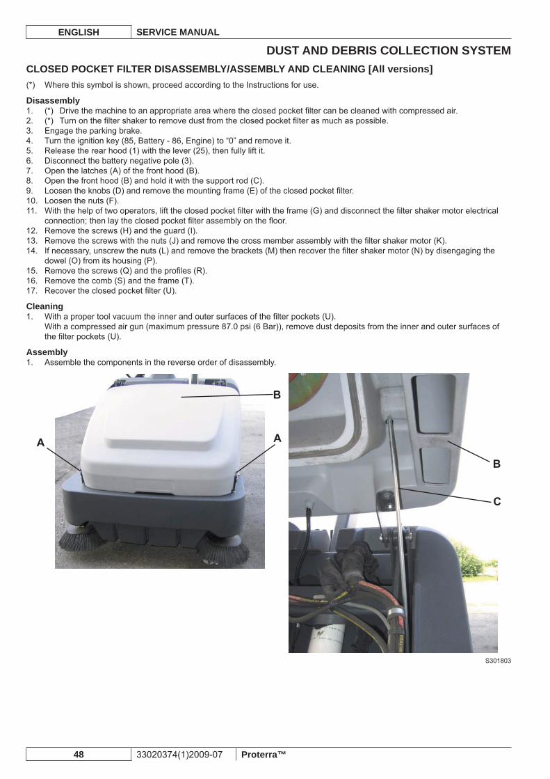
DUST AND DEBRIS COLLECTION SYSTEMENGLISH SERVICE MANUAL
48 33020374(1)2009-07 Proterra™
CLOSED POCKET FILTER DISASSEMBLY/ASSEMBLY AND CLEANING [All versions]Where this symbol is shown, proceed according to the Instructions for use.(*)
Disassembly(*) Drive the machine to an appropriate area where the closed pocket fi lter can be cleaned with compressed air.1. (*) Turn on the fi lter shaker to remove dust from the closed pocket fi lter as much as possible.2. Engage the parking brake.3. Turn the ignition key (85, Battery - 86, Engine) to “0” and remove it.4. Release the rear hood (1) with the lever (25), then fully lift it.5. Disconnect the battery negative pole (3).6. Open the latches (A) of the front hood (B).7. Open the front hood (B) and hold it with the support rod (C).8. Loosen the knobs (D) and remove the mounting frame (E) of the closed pocket fi lter.9. Loosen the nuts (F).10. With the help of two operators, lift the closed pocket fi lter with the frame (G) and disconnect the fi lter shaker motor electrical 11. connection; then lay the closed pocket fi lter assembly on the fl oor.Remove the screws (H) and the guard (I).12. Remove the screws with the nuts (J) and remove the cross member assembly with the fi lter shaker motor (K).13. If necessary, unscrew the nuts (L) and remove the brackets (M) then recover the fi lter shaker motor (N) by disengaging the 14. dowel (O) from its housing (P).Remove the screws (Q) and the profi les (R).15. Remove the comb (S) and the frame (T).16. Recover the closed pocket fi lter (U).17.
CleaningWith a proper tool vacuum the inner and outer surfaces of the fi lter pockets (U).1. With a compressed air gun (maximum pressure 87.0 psi (6 Bar)), remove dust deposits from the inner and outer surfaces of the fi lter pockets (U).
AssemblyAssemble the components in the reverse order of disassembly.1.
S301803
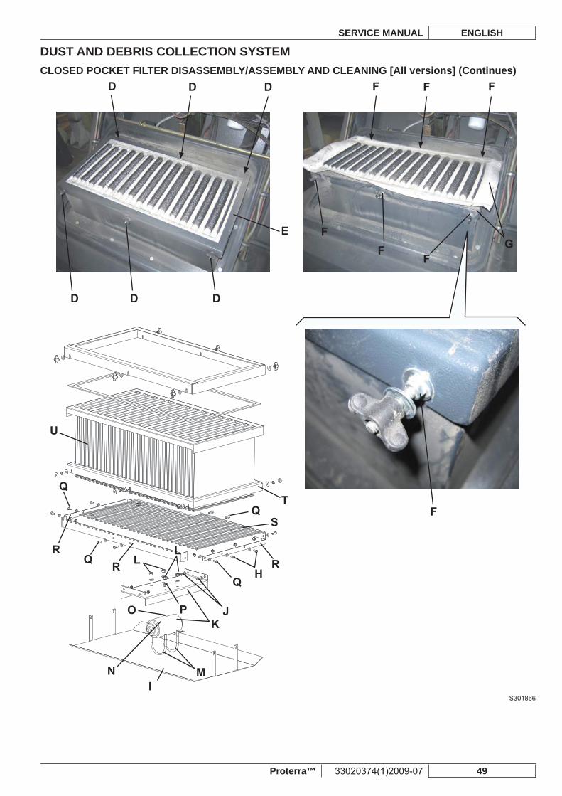
DUST AND DEBRIS COLLECTION SYSTEMSERVICE MANUAL ENGLISH
Proterra™ 33020374(1)2009-07 49
CLOSED POCKET FILTER DISASSEMBLY/ASSEMBLY AND CLEANING [All versions] (Continues)
S301866
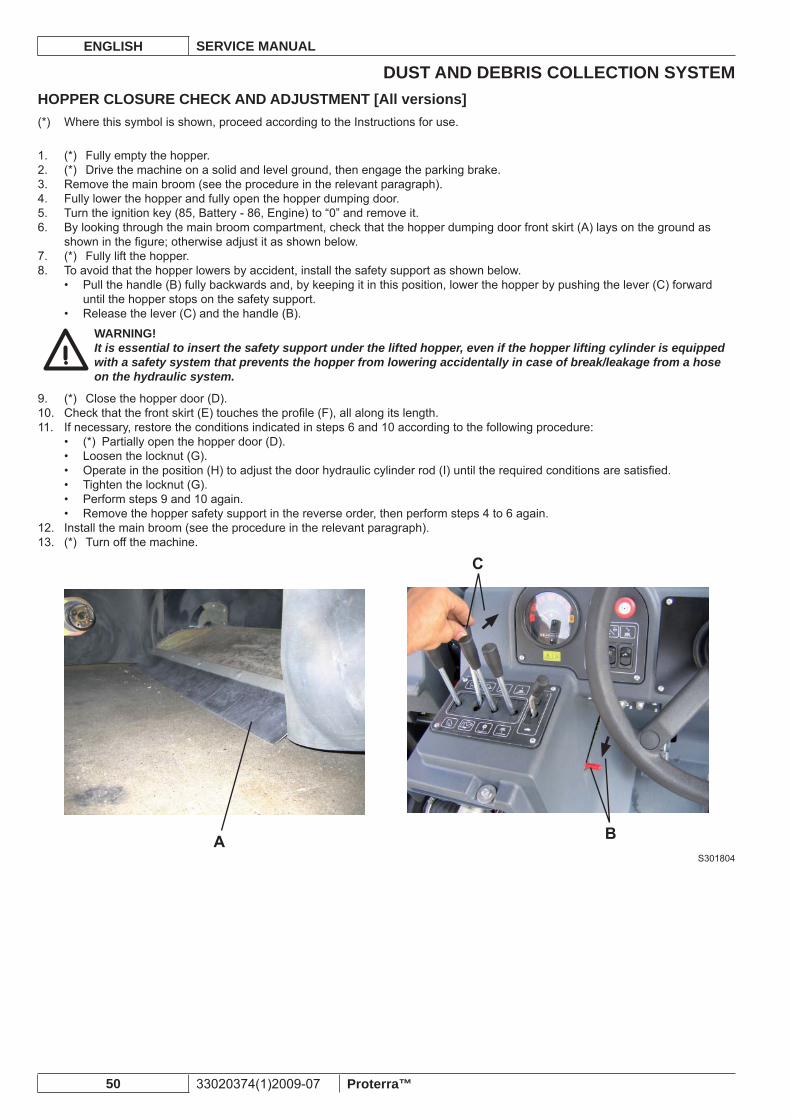
DUST AND DEBRIS COLLECTION SYSTEMENGLISH SERVICE MANUAL
50 33020374(1)2009-07 Proterra™
HOPPER CLOSURE CHECK AND ADJUSTMENT [All versions]Where this symbol is shown, proceed according to the Instructions for use.(*)
(*) Fully empty the hopper.1. (*) Drive the machine on a solid and level ground, then engage the parking brake.2. Remove the main broom (see the procedure in the relevant paragraph).3. Fully lower the hopper and fully open the hopper dumping door.4. Turn the ignition key (85, Battery - 86, Engine) to “0” and remove it.5. By looking through the main broom compartment, check that the hopper dumping door front skirt (A) lays on the ground as 6. shown in the fi gure; otherwise adjust it as shown below.(*) Fully lift the hopper.7. To avoid that the hopper lowers by accident, install the safety support as shown below.8.
Pull the handle (B) fully backwards and, by keeping it in this position, lower the hopper by pushing the lever (C) forward • until the hopper stops on the safety support.Release the lever (C) and the handle (B).•
WARNING!It is essential to insert the safety support under the lifted hopper, even if the hopper lifting cylinder is equipped with a safety system that prevents the hopper from lowering accidentally in case of break/leakage from a hose on the hydraulic system.
(*) Close the hopper door (D).9. Check that the front skirt (E) touches the profi le (F), all along its length.10. If necessary, restore the conditions indicated in steps 6 and 10 according to the following procedure:11.
(*) Partially open the hopper door (D).• Loosen the locknut (G).• Operate in the position (H) to adjust the door hydraulic cylinder rod (I) until the required conditions are satisfi ed.• Tighten the locknut (G).• Perform steps 9 and 10 again.• Remove the hopper safety support in the reverse order, then perform steps 4 to 6 again.•
Install the main broom (see the procedure in the relevant paragraph).12. (*) Turn off the machine.13.
S301804
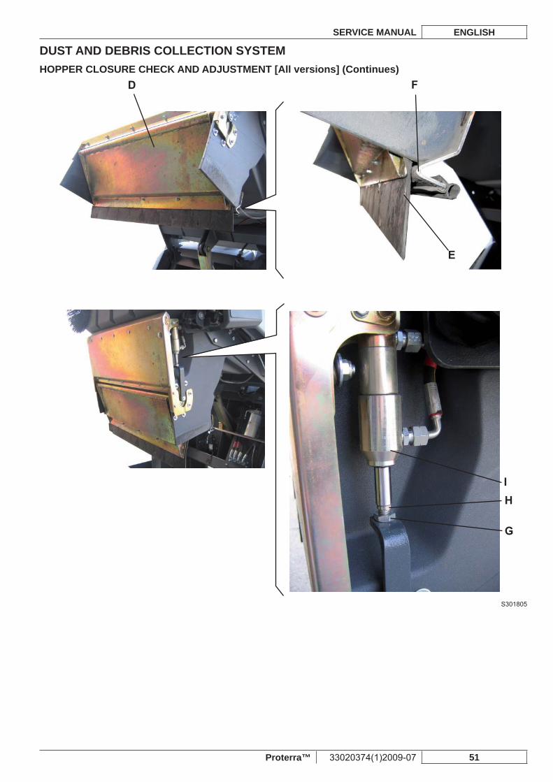
DUST AND DEBRIS COLLECTION SYSTEMSERVICE MANUAL ENGLISH
Proterra™ 33020374(1)2009-07 51
HOPPER CLOSURE CHECK AND ADJUSTMENT [All versions] (Continues)
S301805
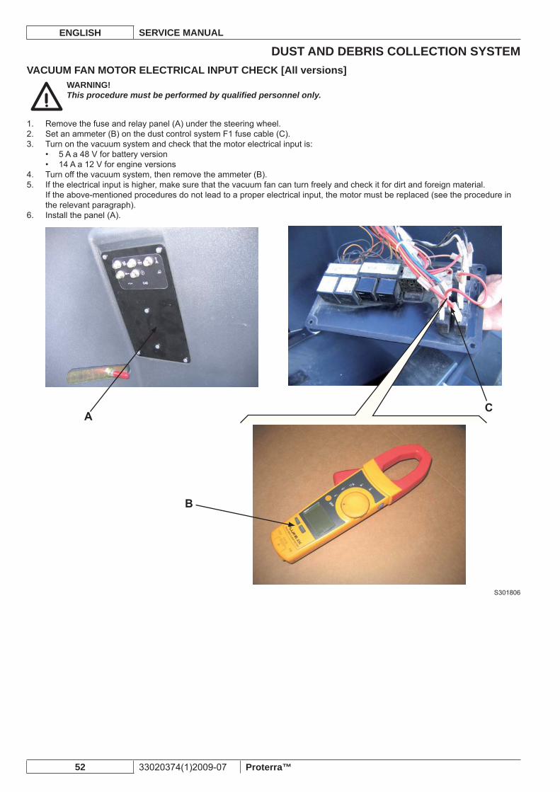
DUST AND DEBRIS COLLECTION SYSTEMENGLISH SERVICE MANUAL
52 33020374(1)2009-07 Proterra™
VACUUM FAN MOTOR ELECTRICAL INPUT CHECK [All versions]WARNING!This procedure must be performed by qualifi ed personnel only.
Remove the fuse and relay panel (A) under the steering wheel.1. Set an ammeter (B) on the dust control system F1 fuse cable (C).2. Turn on the vacuum system and check that the motor electrical input is:3.
5 A a 48 V for battery version• 14 A a 12 V for engine versions•
Turn off the vacuum system, then remove the ammeter (B).4. If the electrical input is higher, make sure that the vacuum fan can turn freely and check it for dirt and foreign material.5. If the above-mentioned procedures do not lead to a proper electrical input, the motor must be replaced (see the procedure in the relevant paragraph).Install the panel (A).6.
S301806
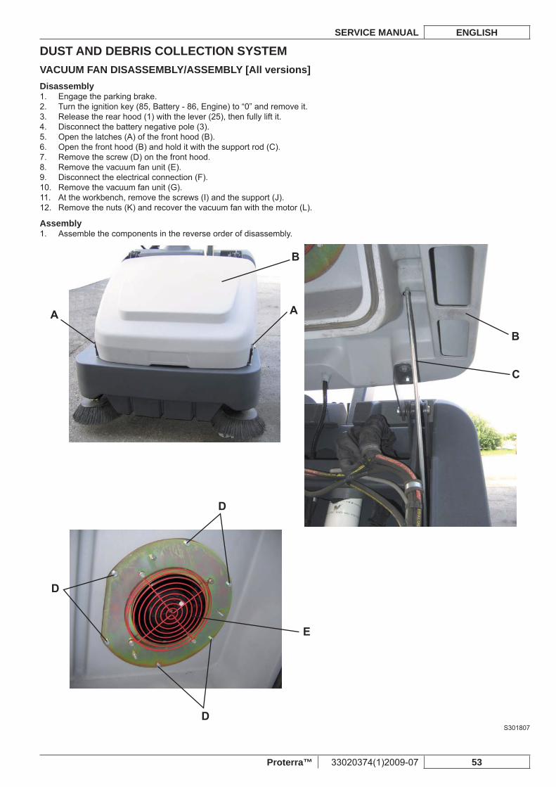
DUST AND DEBRIS COLLECTION SYSTEMSERVICE MANUAL ENGLISH
Proterra™ 33020374(1)2009-07 53
VACUUM FAN DISASSEMBLY/ASSEMBLY [All versions]Disassembly
Engage the parking brake.1. Turn the ignition key (85, Battery - 86, Engine) to “0” and remove it.2. Release the rear hood (1) with the lever (25), then fully lift it.3. Disconnect the battery negative pole (3).4. Open the latches (A) of the front hood (B).5. Open the front hood (B) and hold it with the support rod (C).6. Remove the screw (D) on the front hood.7. Remove the vacuum fan unit (E).8. Disconnect the electrical connection (F).9. Remove the vacuum fan unit (G).10. At the workbench, remove the screws (I) and the support (J).11. Remove the nuts (K) and recover the vacuum fan with the motor (L).12.
AssemblyAssemble the components in the reverse order of disassembly.1.
S301807
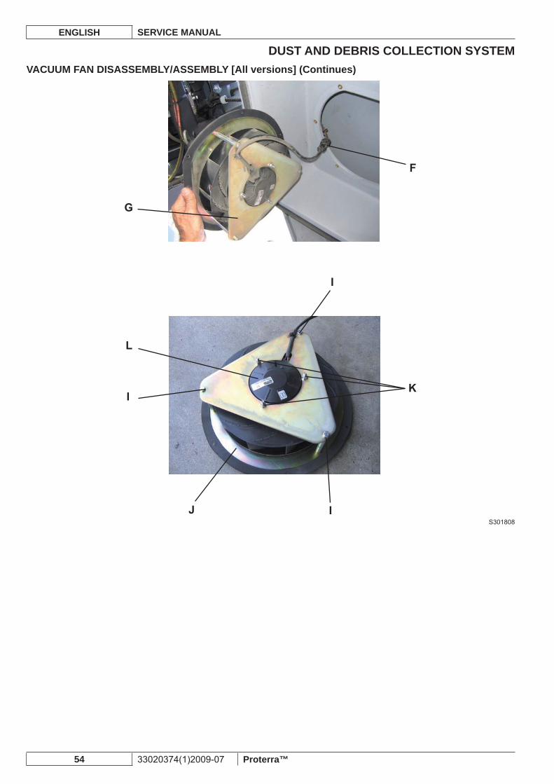
DUST AND DEBRIS COLLECTION SYSTEMENGLISH SERVICE MANUAL
54 33020374(1)2009-07 Proterra™
VACUUM FAN DISASSEMBLY/ASSEMBLY [All versions] (Continues)
S301808
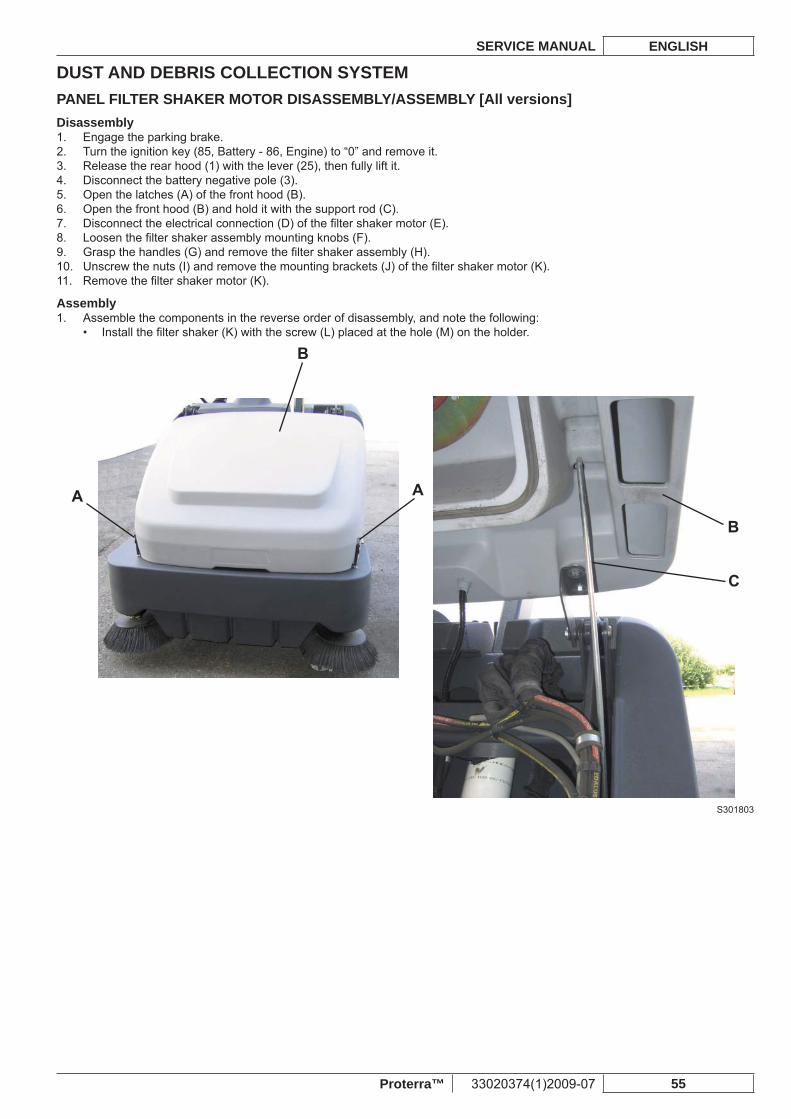
DUST AND DEBRIS COLLECTION SYSTEMSERVICE MANUAL ENGLISH
Proterra™ 33020374(1)2009-07 55
PANEL FILTER SHAKER MOTOR DISASSEMBLY/ASSEMBLY [All versions]Disassembly
Engage the parking brake.1. Turn the ignition key (85, Battery - 86, Engine) to “0” and remove it.2. Release the rear hood (1) with the lever (25), then fully lift it.3. Disconnect the battery negative pole (3).4. Open the latches (A) of the front hood (B).5. Open the front hood (B) and hold it with the support rod (C).6. Disconnect the electrical connection (D) of the fi lter shaker motor (E).7. Loosen the fi lter shaker assembly mounting knobs (F).8. Grasp the handles (G) and remove the fi lter shaker assembly (H).9. Unscrew the nuts (I) and remove the mounting brackets (J) of the fi lter shaker motor (K).10. Remove the fi lter shaker motor (K).11.
AssemblyAssemble the components in the reverse order of disassembly, and note the following:1.
Install the fi lter shaker (K) with the screw (L) placed at the hole (M) on the holder.•
S301803
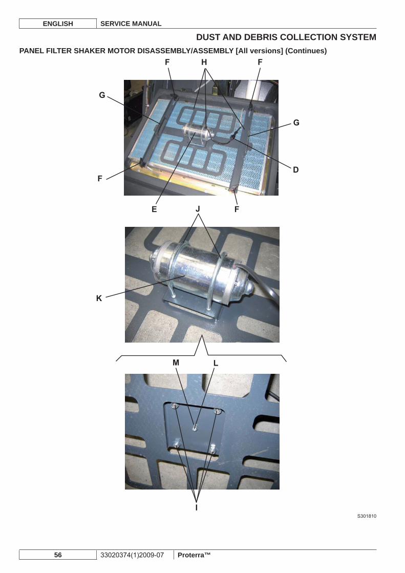
DUST AND DEBRIS COLLECTION SYSTEMENGLISH SERVICE MANUAL
56 33020374(1)2009-07 Proterra™
PANEL FILTER SHAKER MOTOR DISASSEMBLY/ASSEMBLY [All versions] (Continues)
S301810
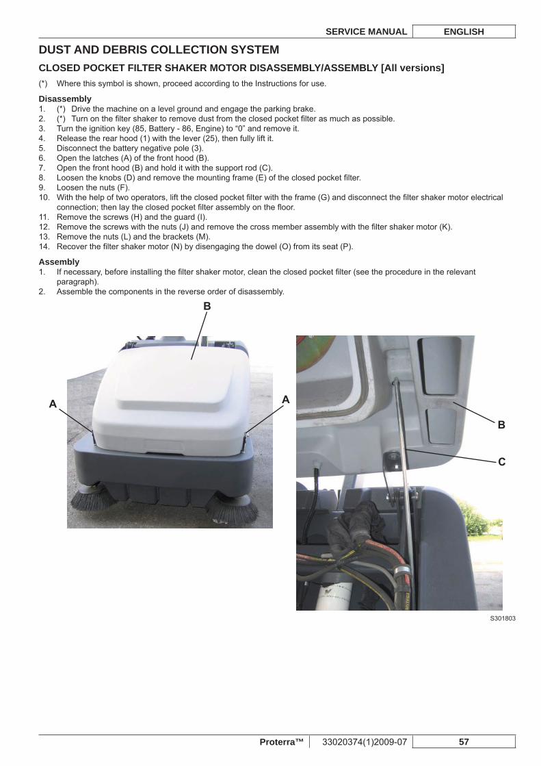
DUST AND DEBRIS COLLECTION SYSTEMSERVICE MANUAL ENGLISH
Proterra™ 33020374(1)2009-07 57
CLOSED POCKET FILTER SHAKER MOTOR DISASSEMBLY/ASSEMBLY [All versions]Where this symbol is shown, proceed according to the Instructions for use.(*)
Disassembly(*) Drive the machine on a level ground and engage the parking brake.1. (*) Turn on the fi lter shaker to remove dust from the closed pocket fi lter as much as possible.2. Turn the ignition key (85, Battery - 86, Engine) to “0” and remove it.3. Release the rear hood (1) with the lever (25), then fully lift it.4. Disconnect the battery negative pole (3).5. Open the latches (A) of the front hood (B).6. Open the front hood (B) and hold it with the support rod (C).7. Loosen the knobs (D) and remove the mounting frame (E) of the closed pocket fi lter.8. Loosen the nuts (F).9. With the help of two operators, lift the closed pocket fi lter with the frame (G) and disconnect the fi lter shaker motor electrical 10. connection; then lay the closed pocket fi lter assembly on the fl oor.Remove the screws (H) and the guard (I).11. Remove the screws with the nuts (J) and remove the cross member assembly with the fi lter shaker motor (K).12. Remove the nuts (L) and the brackets (M).13. Recover the fi lter shaker motor (N) by disengaging the dowel (O) from its seat (P).14.
AssemblyIf necessary, before installing the fi lter shaker motor, clean the closed pocket fi lter (see the procedure in the relevant 1. paragraph).Assemble the components in the reverse order of disassembly.2.
S301803
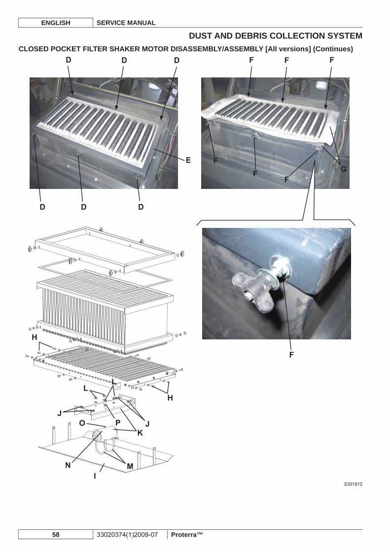
DUST AND DEBRIS COLLECTION SYSTEMENGLISH SERVICE MANUAL
58 33020374(1)2009-07 Proterra™
CLOSED POCKET FILTER SHAKER MOTOR DISASSEMBLY/ASSEMBLY [All versions] (Continues)
S301812
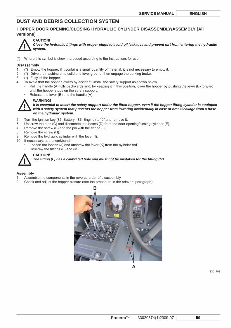
DUST AND DEBRIS COLLECTION SYSTEMSERVICE MANUAL ENGLISH
Proterra™ 33020374(1)2009-07 59
HOPPER DOOR OPENING/CLOSING HYDRAULIC CYLINDER DISASSEMBLY/ASSEMBLY [All versions]
CAUTION!Close the hydraulic fi ttings with proper plugs to avoid oil leakages and prevent dirt from entering the hydraulic system.
Where this symbol is shown, proceed according to the Instructions for use.(*)
Disassembly(*) Empty the hopper; if it contains a small quantity of material, it is not necessary to empty it.1. (*) Drive the machine on a solid and level ground, then engage the parking brake.2. (*) Fully lift the hopper.3. To avoid that the hopper lowers by accident, install the safety support as shown below.4.
Pull the handle (A) fully backwards and, by keeping it in this position, lower the hopper by pushing the lever (B) forward • until the hopper stops on the safety support.Release the lever (B) and the handle (A).•
WARNING!It is essential to insert the safety support under the lifted hopper, even if the hopper lifting cylinder is equipped with a safety system that prevents the hopper from lowering accidentally in case of break/leakage from a hose on the hydraulic system.
Turn the ignition key (85, Battery - 86, Engine) to “0” and remove it.5. Unscrew the nuts (C) and disconnect the hoses (D) from the door opening/closing cylinder (E).6. Remove the screw (F) and the pin with the fl ange (G).7. Remove the screw (H).8. Remove the hydraulic cylinder with the lever (I).9. If necessary, at the workbench:10.
Loosen the loosen (J) and unscrew the lever (K) from the cylinder rod.• Unscrew the fi ttings (L) and (M).•
CAUTION!The fi tting (L) has a calibrated hole and must not be mistaken for the fi tting (M).
AssemblyAssemble the components in the reverse order of disassembly.1. Check and adjust the hopper closure (see the procedure in the relevant paragraph).2.
S301792
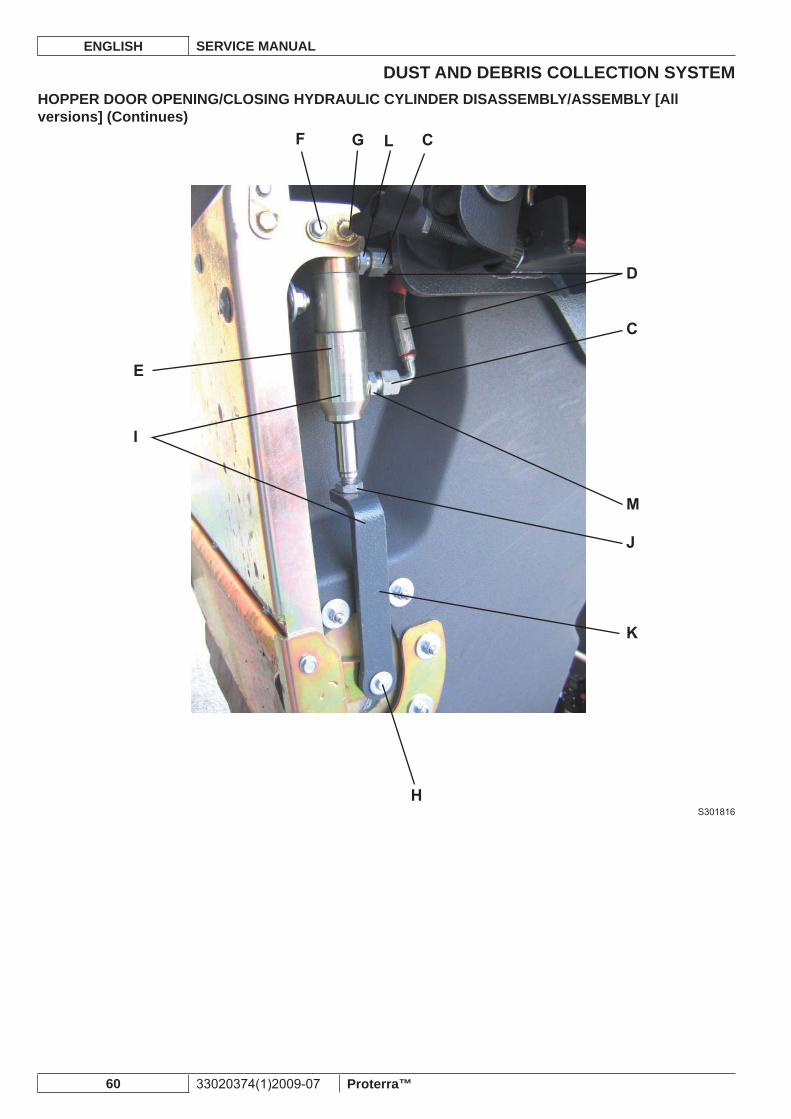
DUST AND DEBRIS COLLECTION SYSTEMENGLISH SERVICE MANUAL
60 33020374(1)2009-07 Proterra™
HOPPER DOOR OPENING/CLOSING HYDRAULIC CYLINDER DISASSEMBLY/ASSEMBLY [All versions] (Continues)
S301816
DUST AND DEBRIS COLLECTION SYSTEMSERVICE MANUAL ENGLISH
Proterra™ 33020374(1)2009-07 61
HOPPER LIFTING HYDRAULIC CYLINDER DISASSEMBLY/ASSEMBLY [All versions]CAUTION!Close the hydraulic fi ttings with proper plugs to avoid oil leakages and prevent dirt from entering the hydraulic system.
CAUTION!If necessary, remove “Bonded” washers and replace them.
Where this symbol is shown, proceed according to the Instructions for use.(*)
Disassembly(*) Empty the hopper.1. (*) Drive the machine on a solid and level ground, then engage the parking brake.2. (*) Lift the hopper nearly to the end-of-stroke.3. Open the hopper door (A).Lower the hopper until the side profi les (B) are horizontal, then lay the rear profi le (C) on a proper holder (D). Take into consideration that, when removing the hydraulic cylinder, the holder (D) must bear the whole weight of the hopper (approximate weight: 661 lb (300 kg)).If necessary, before laying the profi le (C) on the holder (D), remove the gasket (E) to prevent it from damage.Turn the ignition key (85, Battery - 86, Engine) to “0” and remove it.4. Release the rear hood (1) with the lever (25), then fully lift it.5. Remove the retaining ring (F).6. Mark the position of the shim rings (G) for proper assembly.7. Remove the pin (H) and recover the shim rings (G).8. Remove the rod (I).9. Disconnect the hoses (J) from the hopper hydraulic lifting cylinder (K).10.
WARNING!Hydraulic system oil is highly corrosive, wear rubber gloves.
Remove the screw (L) of the fl ange with mounting pin (M) of the hydraulic cylinder base.11. On the opposite side, move aside the cool air vacuum hose (N) of the engine.12. Tap on the mounting pin (O) of the hydraulic cylinder bottom and remove it.13. Remove the hopper lifting cylinder (K) from the front side of the machine.14.
AssemblyAssemble the components in the reverse order of disassembly.1. (*) Start the machine and check the hopper for proper lifting/lowering operation; then stop the machine, check the hydraulic 2. system oil level (see the procedure in the relevant paragraph) and, if necessary, top up.
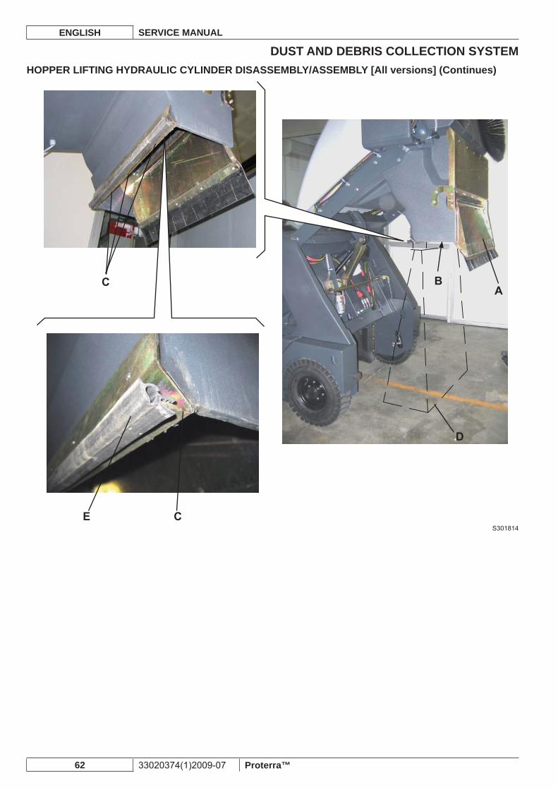
DUST AND DEBRIS COLLECTION SYSTEMENGLISH SERVICE MANUAL
62 33020374(1)2009-07 Proterra™
HOPPER LIFTING HYDRAULIC CYLINDER DISASSEMBLY/ASSEMBLY [All versions] (Continues)
S301814
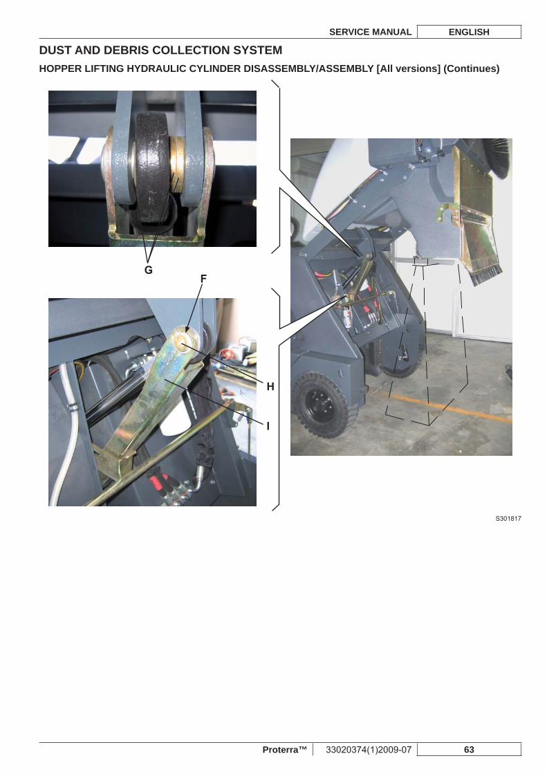
DUST AND DEBRIS COLLECTION SYSTEMSERVICE MANUAL ENGLISH
Proterra™ 33020374(1)2009-07 63
HOPPER LIFTING HYDRAULIC CYLINDER DISASSEMBLY/ASSEMBLY [All versions] (Continues)
S301817
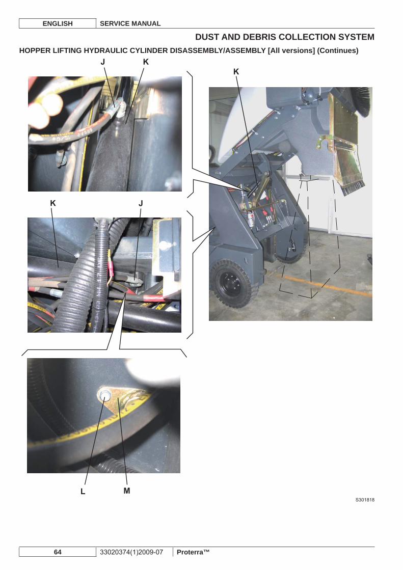
DUST AND DEBRIS COLLECTION SYSTEMENGLISH SERVICE MANUAL
64 33020374(1)2009-07 Proterra™
HOPPER LIFTING HYDRAULIC CYLINDER DISASSEMBLY/ASSEMBLY [All versions] (Continues)
S301818
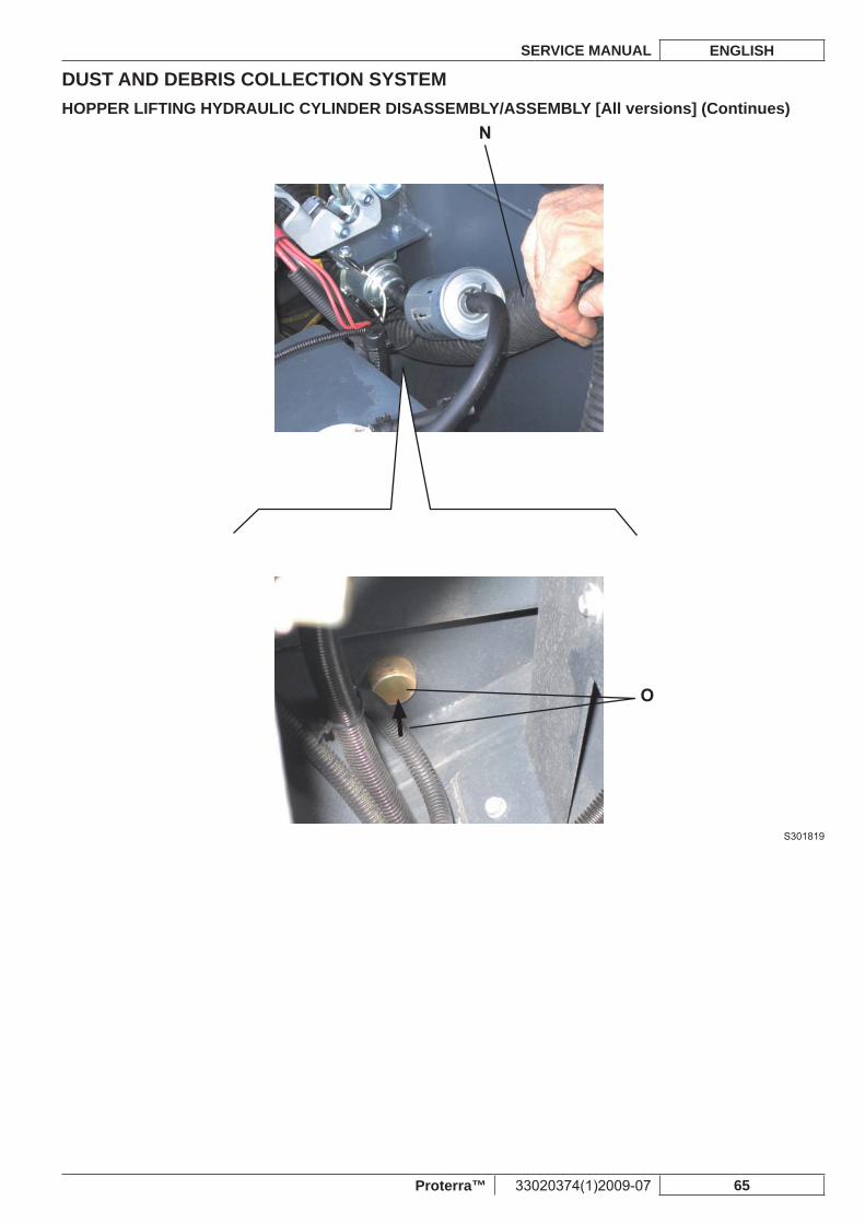
DUST AND DEBRIS COLLECTION SYSTEMSERVICE MANUAL ENGLISH
Proterra™ 33020374(1)2009-07 65
HOPPER LIFTING HYDRAULIC CYLINDER DISASSEMBLY/ASSEMBLY [All versions] (Continues)
S301819
DUST AND DEBRIS COLLECTION SYSTEMENGLISH SERVICE MANUAL
66 33020374(1)2009-07 Proterra™
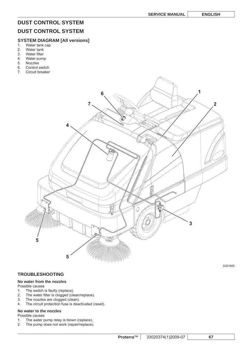
DUST CONTROL SYSTEMSERVICE MANUAL ENGLISH
Proterra™ 33020374(1)2009-07 67
DUST CONTROL SYSTEMSYSTEM DIAGRAM [All versions]
Water tank cap1. Water tank2. Water fi lter3. Water pump4. Nozzles5. Control switch6. Circuit breaker7.
1
2
3
4
5
5
7
6
S301809
TROUBLESHOOTINGNo water from the nozzlesPossible causes
The switch is faulty (replace).1. The water fi lter is clogged (clean/replace).2. The nozzles are clogged (clean).3. The circuit protection fuse is deactivated (reset).4.
No water to the nozzlesPossible causes
The water pump relay is blown (replace).1. The pump does not work (repair/replace).2.
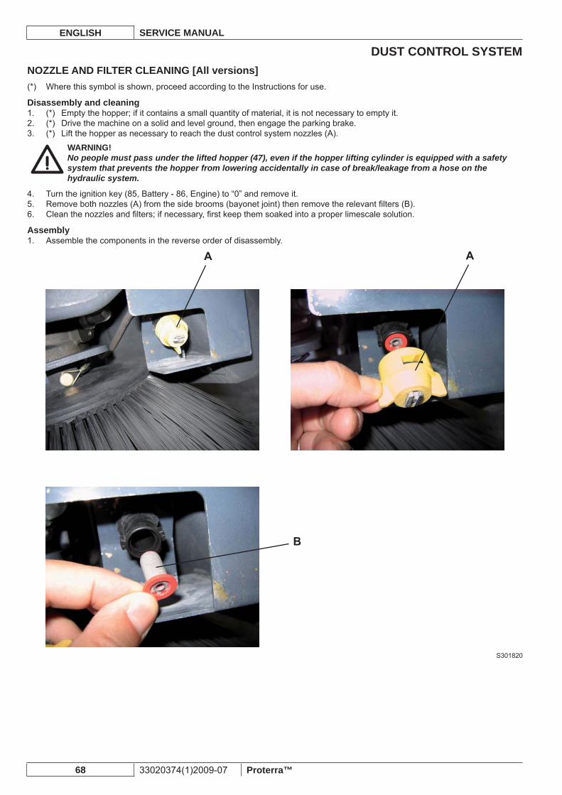
DUST CONTROL SYSTEMENGLISH SERVICE MANUAL
68 33020374(1)2009-07 Proterra™
NOZZLE AND FILTER CLEANING [All versions]Where this symbol is shown, proceed according to the Instructions for use.(*)
Disassembly and cleaning(*) Empty the hopper; if it contains a small quantity of material, it is not necessary to empty it.1. (*) Drive the machine on a solid and level ground, then engage the parking brake.2. (*) Lift the hopper as necessary to reach the dust control system nozzles (A).3.
WARNING!No people must pass under the lifted hopper (47), even if the hopper lifting cylinder is equipped with a safety system that prevents the hopper from lowering accidentally in case of break/leakage from a hose on the hydraulic system.
Turn the ignition key (85, Battery - 86, Engine) to “0” and remove it.4. Remove both nozzles (A) from the side brooms (bayonet joint) then remove the relevant fi lters (B).5. Clean the nozzles and fi lters; if necessary, fi rst keep them soaked into a proper limescale solution.6.
AssemblyAssemble the components in the reverse order of disassembly.1.
S301820
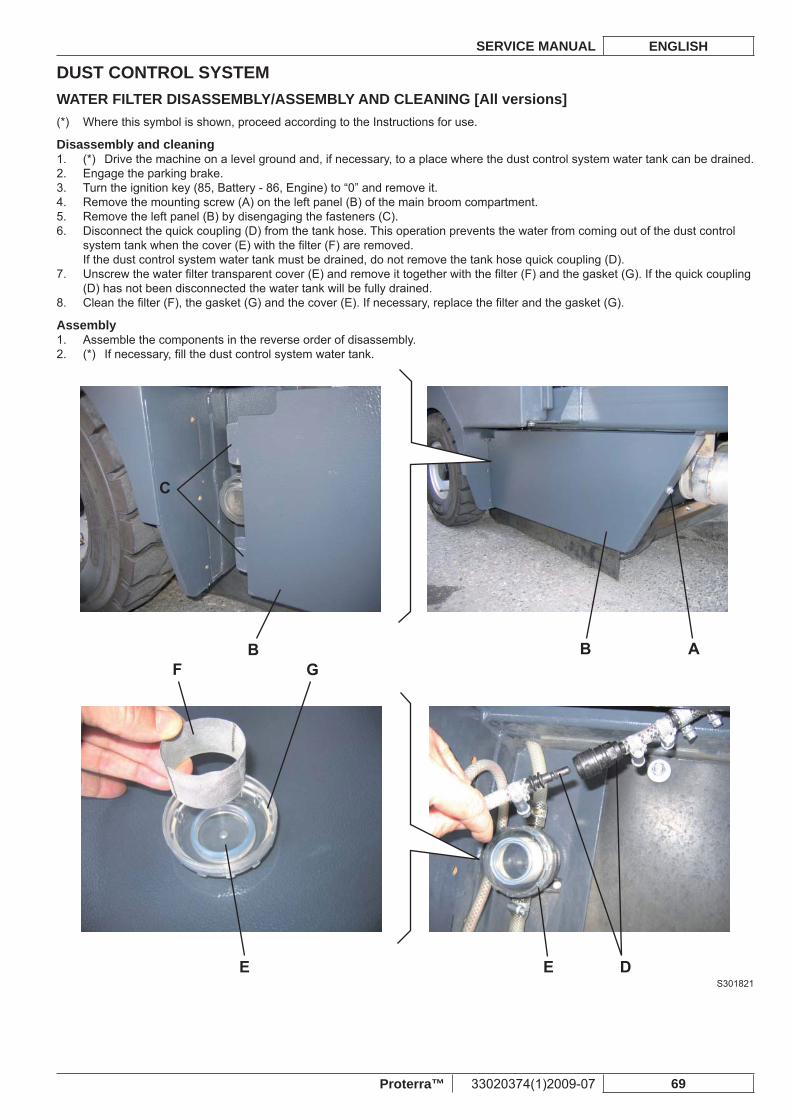
DUST CONTROL SYSTEMSERVICE MANUAL ENGLISH
Proterra™ 33020374(1)2009-07 69
WATER FILTER DISASSEMBLY/ASSEMBLY AND CLEANING [All versions]Where this symbol is shown, proceed according to the Instructions for use.(*)
Disassembly and cleaning(*) Drive the machine on a level ground and, if necessary, to a place where the dust control system water tank can be drained.1. Engage the parking brake.2. Turn the ignition key (85, Battery - 86, Engine) to “0” and remove it.3. Remove the mounting screw (A) on the left panel (B) of the main broom compartment.4. Remove the left panel (B) by disengaging the fasteners (C).5. Disconnect the quick coupling (D) from the tank hose. This operation prevents the water from coming out of the dust control 6. system tank when the cover (E) with the fi lter (F) are removed.If the dust control system water tank must be drained, do not remove the tank hose quick coupling (D).Unscrew the water fi lter transparent cover (E) and remove it together with the fi lter (F) and the gasket (G). If the quick coupling 7. (D) has not been disconnected the water tank will be fully drained.Clean the fi lter (F), the gasket (G) and the cover (E). If necessary, replace the fi lter and the gasket (G).8.
AssemblyAssemble the components in the reverse order of disassembly.1. (*) If necessary, fi ll the dust control system water tank.2.
S301821
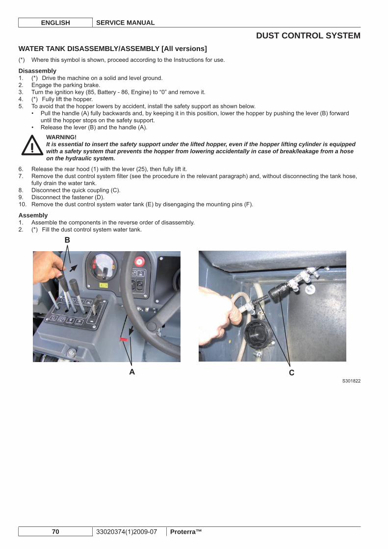
DUST CONTROL SYSTEMENGLISH SERVICE MANUAL
70 33020374(1)2009-07 Proterra™
WATER TANK DISASSEMBLY/ASSEMBLY [All versions]Where this symbol is shown, proceed according to the Instructions for use.(*)
Disassembly(*) Drive the machine on a solid and level ground.1. Engage the parking brake.2. Turn the ignition key (85, Battery - 86, Engine) to “0” and remove it.3. (*) Fully lift the hopper.4. To avoid that the hopper lowers by accident, install the safety support as shown below.5.
Pull the handle (A) fully backwards and, by keeping it in this position, lower the hopper by pushing the lever (B) forward • until the hopper stops on the safety support.Release the lever (B) and the handle (A).•
WARNING!It is essential to insert the safety support under the lifted hopper, even if the hopper lifting cylinder is equipped with a safety system that prevents the hopper from lowering accidentally in case of break/leakage from a hose on the hydraulic system.
Release the rear hood (1) with the lever (25), then fully lift it.6. Remove the dust control system fi lter (see the procedure in the relevant paragraph) and, without disconnecting the tank hose, 7. fully drain the water tank.Disconnect the quick coupling (C).8. Disconnect the fastener (D).9. Remove the dust control system water tank (E) by disengaging the mounting pins (F).10.
AssemblyAssemble the components in the reverse order of disassembly.1. (*) Fill the dust control system water tank.2.
S301822
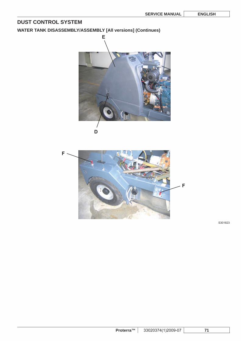
DUST CONTROL SYSTEMSERVICE MANUAL ENGLISH
Proterra™ 33020374(1)2009-07 71
WATER TANK DISASSEMBLY/ASSEMBLY [All versions] (Continues)
S301823
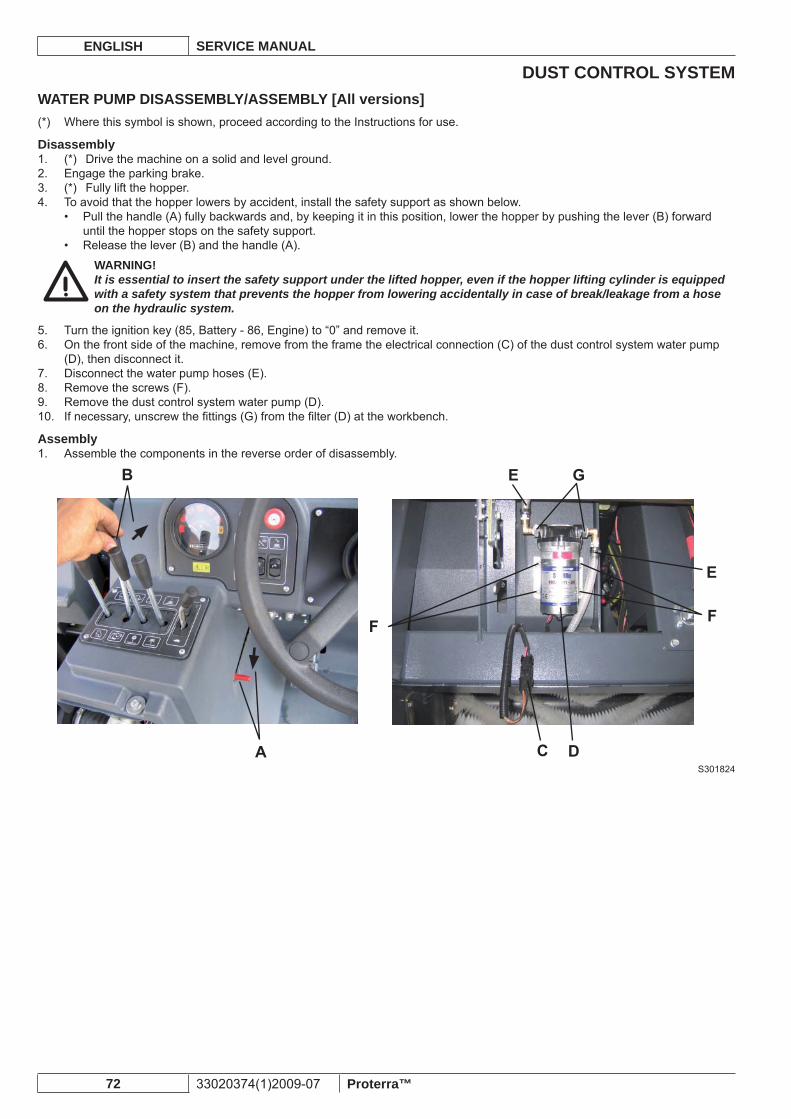
DUST CONTROL SYSTEMENGLISH SERVICE MANUAL
72 33020374(1)2009-07 Proterra™
WATER PUMP DISASSEMBLY/ASSEMBLY [All versions]Where this symbol is shown, proceed according to the Instructions for use.(*)
Disassembly(*) Drive the machine on a solid and level ground.1. Engage the parking brake.2. (*) Fully lift the hopper.3. To avoid that the hopper lowers by accident, install the safety support as shown below.4.
Pull the handle (A) fully backwards and, by keeping it in this position, lower the hopper by pushing the lever (B) forward • until the hopper stops on the safety support.Release the lever (B) and the handle (A).•
WARNING!It is essential to insert the safety support under the lifted hopper, even if the hopper lifting cylinder is equipped with a safety system that prevents the hopper from lowering accidentally in case of break/leakage from a hose on the hydraulic system.
Turn the ignition key (85, Battery - 86, Engine) to “0” and remove it.5. On the front side of the machine, remove from the frame the electrical connection (C) of the dust control system water pump 6. (D), then disconnect it.Disconnect the water pump hoses (E).7. Remove the screws (F).8. Remove the dust control system water pump (D).9. If necessary, unscrew the fi ttings (G) from the fi lter (D) at the workbench.10.
AssemblyAssemble the components in the reverse order of disassembly.1.
S301824
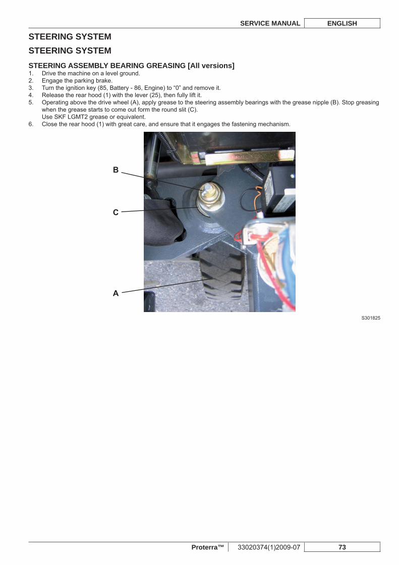
STEERING SYSTEMSERVICE MANUAL ENGLISH
Proterra™ 33020374(1)2009-07 73
STEERING SYSTEMSTEERING ASSEMBLY BEARING GREASING [All versions]
Drive the machine on a level ground.1. Engage the parking brake.2. Turn the ignition key (85, Battery - 86, Engine) to “0” and remove it.3. Release the rear hood (1) with the lever (25), then fully lift it.4. Operating above the drive wheel (A), apply grease to the steering assembly bearings with the grease nipple (B). Stop greasing 5. when the grease starts to come out form the round slit (C).Use SKF LGMT2 grease or equivalent.Close the rear hood (1) with great care, and ensure that it engages the fastening mechanism.6.
S301825
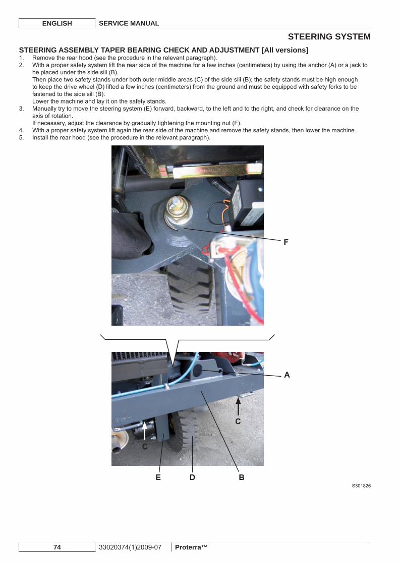
STEERING SYSTEMENGLISH SERVICE MANUAL
74 33020374(1)2009-07 Proterra™
STEERING ASSEMBLY TAPER BEARING CHECK AND ADJUSTMENT [All versions]Remove the rear hood (see the procedure in the relevant paragraph).1. With a proper safety system lift the rear side of the machine for a few inches (centimeters) by using the anchor (A) or a jack to 2. be placed under the side sill (B).Then place two safety stands under both outer middle areas (C) of the side sill (B); the safety stands must be high enough to keep the drive wheel (D) lifted a few inches (centimeters) from the ground and must be equipped with safety forks to be fastened to the side sill (B).Lower the machine and lay it on the safety stands.Manually try to move the steering system (E) forward, backward, to the left and to the right, and check for clearance on the 3. axis of rotation.If necessary, adjust the clearance by gradually tightening the mounting nut (F).With a proper safety system lift again the rear side of the machine and remove the safety stands, then lower the machine.4. Install the rear hood (see the procedure in the relevant paragraph).5.
S301826
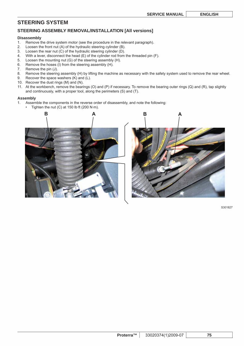
STEERING SYSTEMSERVICE MANUAL ENGLISH
Proterra™ 33020374(1)2009-07 75
STEERING ASSEMBLY REMOVAL/INSTALLATION [All versions]Disassembly
Remove the drive system motor (see the procedure in the relevant paragraph).1. Loosen the front nut (A) of the hydraulic steering cylinder (B).2. Loosen the rear nut (C) of the hydraulic steering cylinder (D).3. With a lever, disconnect the head (E) of the cylinder rod from the threaded pin (F).4. Loosen the mounting nut (G) of the steering assembly (H).5. Remove the hoses (I) from the steering assembly (H).6. Remove the pin (J).7. Remove the steering assembly (H) by lifting the machine as necessary with the safety system used to remove the rear wheel.8. Recover the space washers (K) and (L).9. Recover the dust rings (M) and (N).10. At the workbench, remove the bearings (O) and (P) if necessary. To remove the bearing outer rings (Q) and (R), tap slightly 11. and continuously, with a proper tool, along the perimeters (S) and (T).
AssemblyAssemble the components in the reverse order of disassembly, and note the following:1.
Tighten the nut (C) at 150 lb·ft (200 N·m).•
S301827
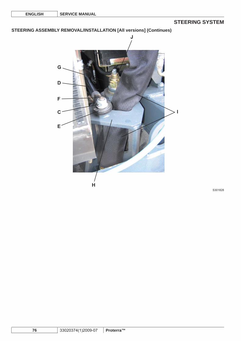
STEERING SYSTEMENGLISH SERVICE MANUAL
76 33020374(1)2009-07 Proterra™
STEERING ASSEMBLY REMOVAL/INSTALLATION [All versions] (Continues)
S301828
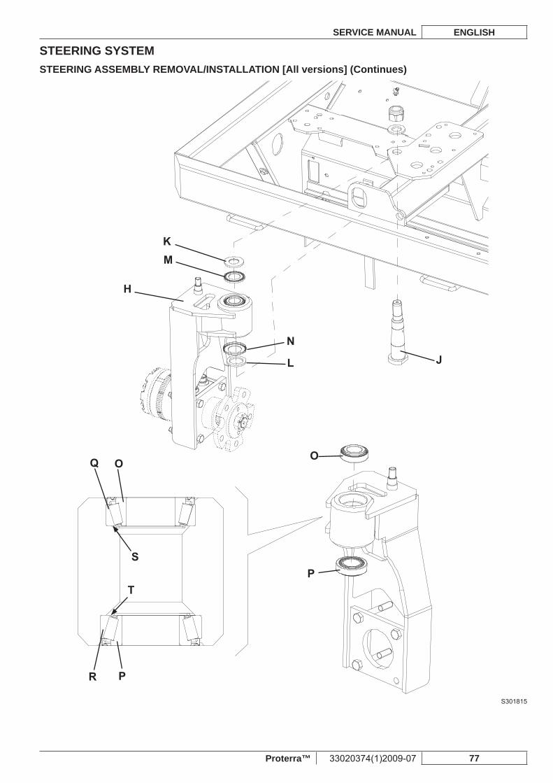
STEERING SYSTEMSERVICE MANUAL ENGLISH
Proterra™ 33020374(1)2009-07 77
STEERING ASSEMBLY REMOVAL/INSTALLATION [All versions] (Continues)
S301815
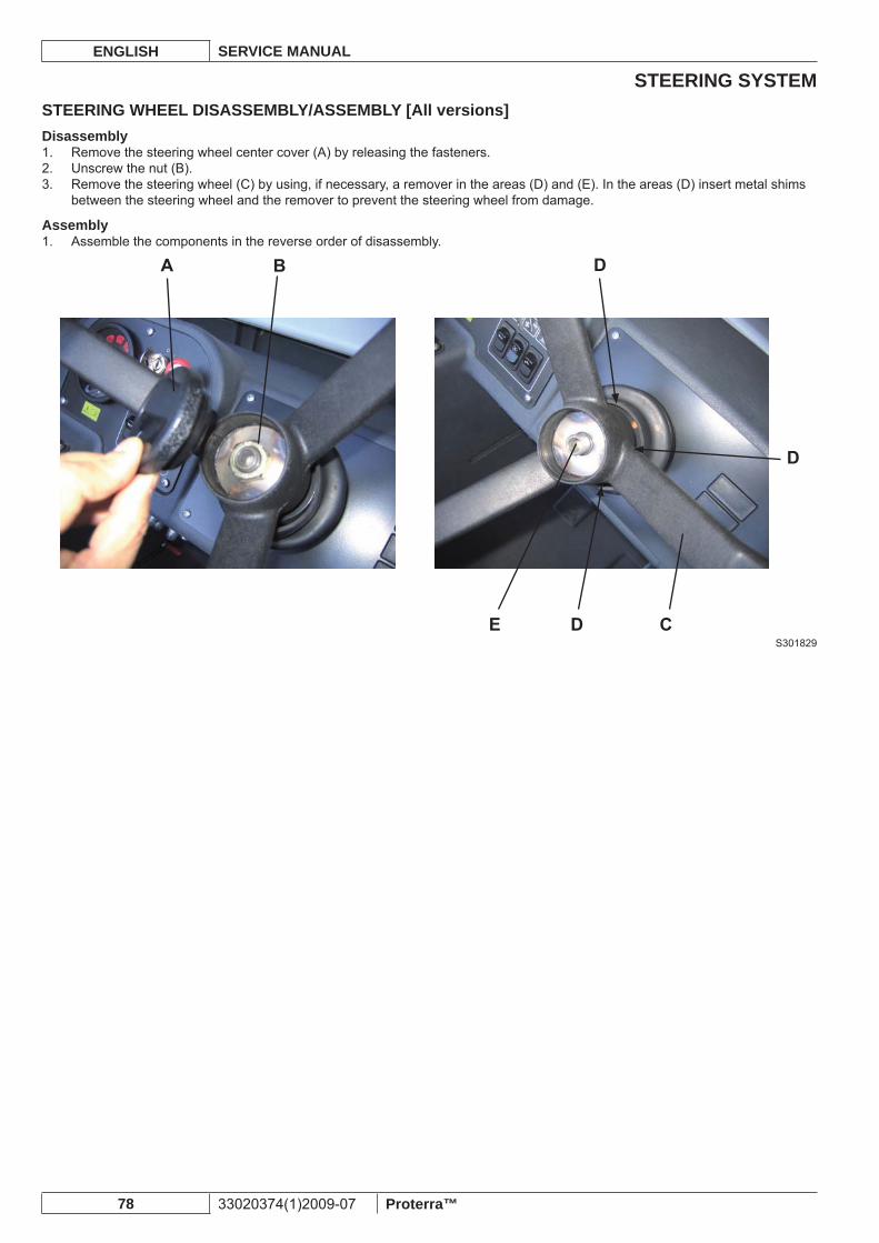
STEERING SYSTEMENGLISH SERVICE MANUAL
78 33020374(1)2009-07 Proterra™
STEERING WHEEL DISASSEMBLY/ASSEMBLY [All versions]Disassembly
Remove the steering wheel center cover (A) by releasing the fasteners.1. Unscrew the nut (B).2. Remove the steering wheel (C) by using, if necessary, a remover in the areas (D) and (E). In the areas (D) insert metal shims 3. between the steering wheel and the remover to prevent the steering wheel from damage.
AssemblyAssemble the components in the reverse order of disassembly.1.
S301829
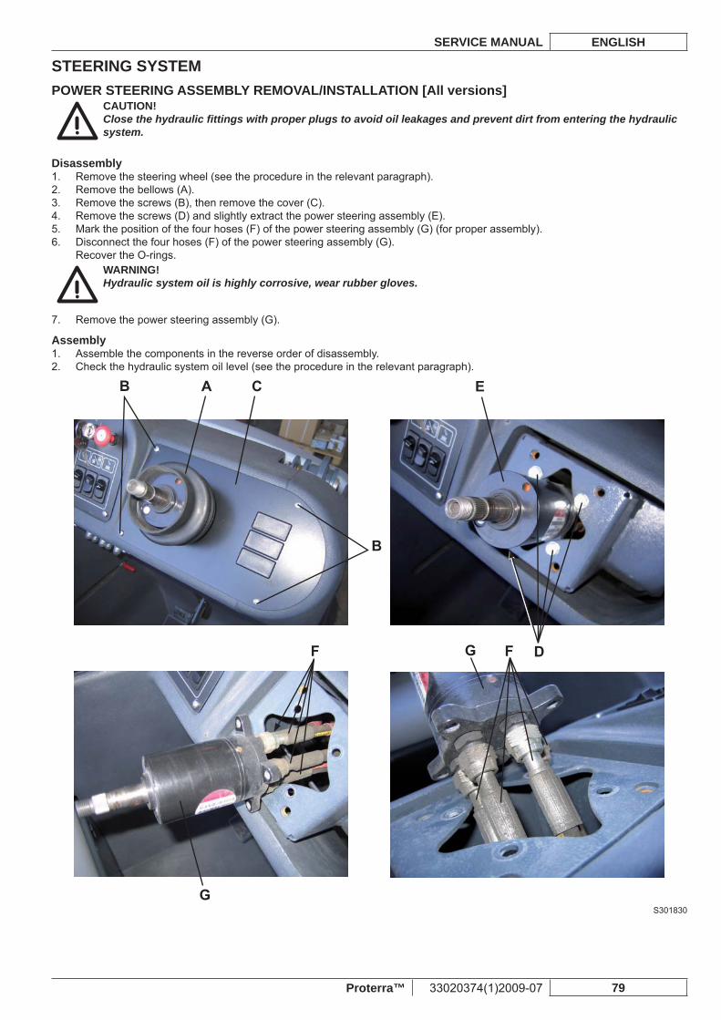
STEERING SYSTEMSERVICE MANUAL ENGLISH
Proterra™ 33020374(1)2009-07 79
POWER STEERING ASSEMBLY REMOVAL/INSTALLATION [All versions]CAUTION!Close the hydraulic fi ttings with proper plugs to avoid oil leakages and prevent dirt from entering the hydraulic system.
DisassemblyRemove the steering wheel (see the procedure in the relevant paragraph).1. Remove the bellows (A).2. Remove the screws (B), then remove the cover (C).3. Remove the screws (D) and slightly extract the power steering assembly (E).4. Mark the position of the four hoses (F) of the power steering assembly (G) (for proper assembly).5. Disconnect the four hoses (F) of the power steering assembly (G).6. Recover the O-rings.
WARNING!Hydraulic system oil is highly corrosive, wear rubber gloves.
Remove the power steering assembly (G).7.
AssemblyAssemble the components in the reverse order of disassembly.1. Check the hydraulic system oil level (see the procedure in the relevant paragraph).2.
S301830
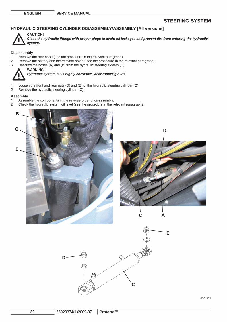
STEERING SYSTEMENGLISH SERVICE MANUAL
80 33020374(1)2009-07 Proterra™
HYDRAULIC STEERING CYLINDER DISASSEMBLY/ASSEMBLY [All versions]CAUTION!Close the hydraulic fi ttings with proper plugs to avoid oil leakages and prevent dirt from entering the hydraulic system.
DisassemblyRemove the rear hood (see the procedure in the relevant paragraph).1. Remove the battery and the relevant holder (see the procedure in the relevant paragraph).2. Unscrew the hoses (A) and (B) from the hydraulic steering system (C).3.
WARNING!Hydraulic system oil is highly corrosive, wear rubber gloves.
Loosen the front and rear nuts (D) and (E) of the hydraulic steering cylinder (C).4. Remove the hydraulic steering cylinder (C).5.
AssemblyAssemble the components in the reverse order of disassembly.1. Check the hydraulic system oil level (see the procedure in the relevant paragraph).2.
S301831
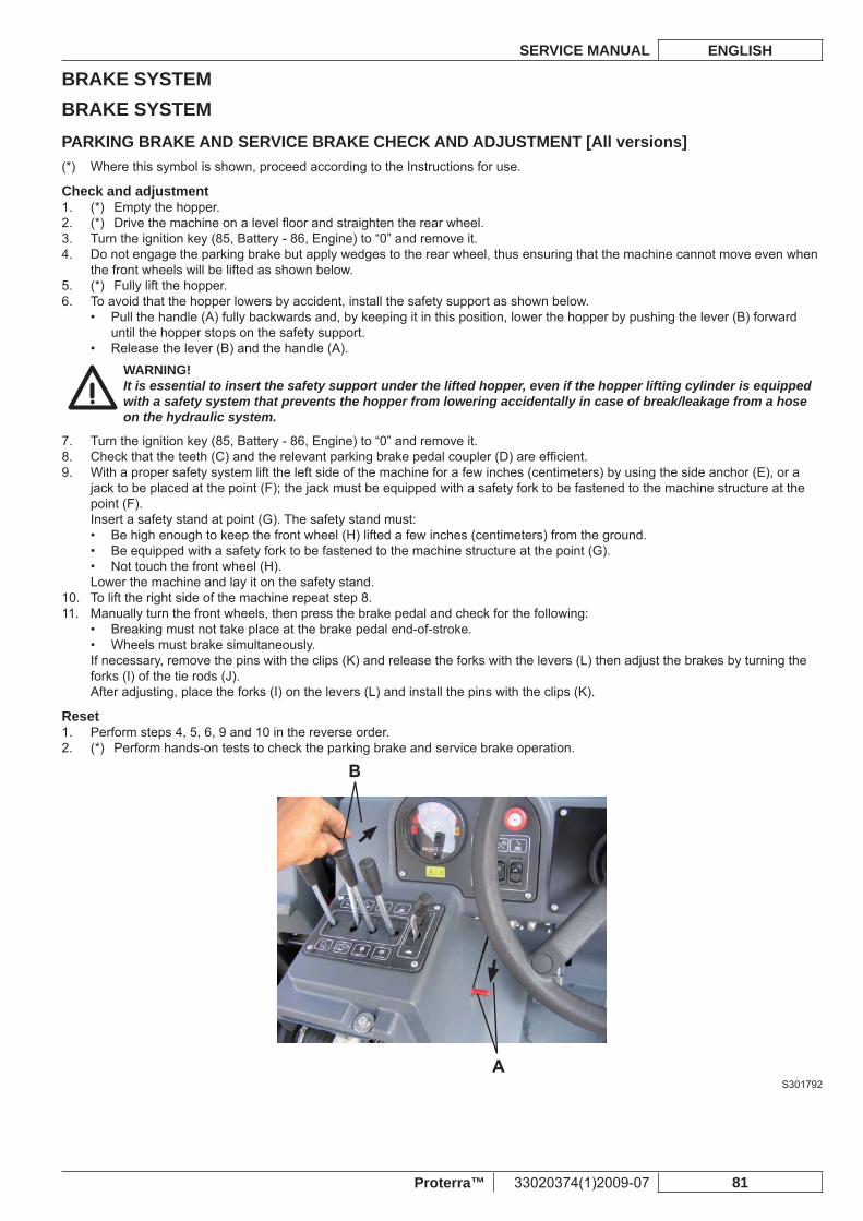
BRAKE SYSTEMSERVICE MANUAL ENGLISH
Proterra™ 33020374(1)2009-07 81
BRAKE SYSTEMPARKING BRAKE AND SERVICE BRAKE CHECK AND ADJUSTMENT [All versions]
Where this symbol is shown, proceed according to the Instructions for use.(*)
Check and adjustment(*) Empty the hopper.1. (*) Drive the machine on a level fl oor and straighten the rear wheel.2. Turn the ignition key (85, Battery - 86, Engine) to “0” and remove it.3. Do not engage the parking brake but apply wedges to the rear wheel, thus ensuring that the machine cannot move even when 4. the front wheels will be lifted as shown below.(*) Fully lift the hopper.5. To avoid that the hopper lowers by accident, install the safety support as shown below.6.
Pull the handle (A) fully backwards and, by keeping it in this position, lower the hopper by pushing the lever (B) forward • until the hopper stops on the safety support.Release the lever (B) and the handle (A).•
WARNING!It is essential to insert the safety support under the lifted hopper, even if the hopper lifting cylinder is equipped with a safety system that prevents the hopper from lowering accidentally in case of break/leakage from a hose on the hydraulic system.
Turn the ignition key (85, Battery - 86, Engine) to “0” and remove it.7. Check that the teeth (C) and the relevant parking brake pedal coupler (D) are effi cient.8. With a proper safety system lift the left side of the machine for a few inches (centimeters) by using the side anchor (E), or a 9. jack to be placed at the point (F); the jack must be equipped with a safety fork to be fastened to the machine structure at the point (F).Insert a safety stand at point (G). The safety stand must:
Be high enough to keep the front wheel (H) lifted a few inches (centimeters) from the ground.• Be equipped with a safety fork to be fastened to the machine structure at the point (G).• Not touch the front wheel (H).•
Lower the machine and lay it on the safety stand.To lift the right side of the machine repeat step 8.10. Manually turn the front wheels, then press the brake pedal and check for the following:11.
Breaking must not take place at the brake pedal end-of-stroke.• Wheels must brake simultaneously.•
If necessary, remove the pins with the clips (K) and release the forks with the levers (L) then adjust the brakes by turning the forks (I) of the tie rods (J).After adjusting, place the forks (I) on the levers (L) and install the pins with the clips (K).
ResetPerform steps 4, 5, 6, 9 and 10 in the reverse order.1. (*) Perform hands-on tests to check the parking brake and service brake operation.2.
S301792
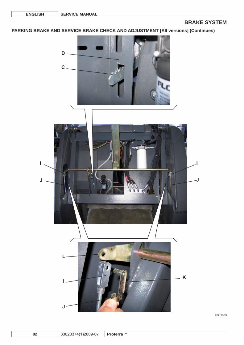
BRAKE SYSTEMENGLISH SERVICE MANUAL
82 33020374(1)2009-07 Proterra™
PARKING BRAKE AND SERVICE BRAKE CHECK AND ADJUSTMENT [All versions] (Continues)
S301833
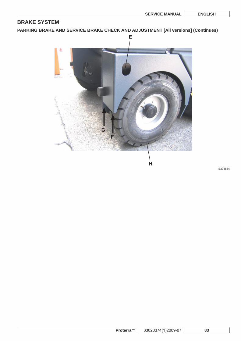
BRAKE SYSTEMSERVICE MANUAL ENGLISH
Proterra™ 33020374(1)2009-07 83
PARKING BRAKE AND SERVICE BRAKE CHECK AND ADJUSTMENT [All versions] (Continues)
S301834
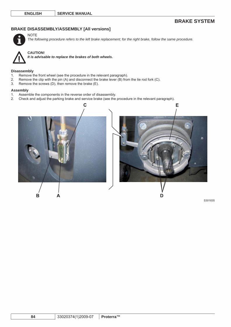
BRAKE SYSTEMENGLISH SERVICE MANUAL
84 33020374(1)2009-07 Proterra™
BRAKE DISASSEMBLY/ASSEMBLY [All versions]NOTEThe following procedure refers to the left brake replacement; for the right brake, follow the same procedure.
CAUTION!It is advisable to replace the brakes of both wheels.
DisassemblyRemove the front wheel (see the procedure in the relevant paragraph).1. Remove the clip with the pin (A) and disconnect the brake lever (B) from the tie rod fork (C).2. Remove the screws (D), then remove the brake (E).3.
AssemblyAssemble the components in the reverse order of disassembly.1. Check and adjust the parking brake and service brake (see the procedure in the relevant paragraph).2.
S301835
DRIVE SYSTEMSERVICE MANUAL ENGLISH
Proterra™ 33020374(1)2009-07 85
DRIVE SYSTEMTROUBLESHOOTING [All versions]The machine does not move.Possible causes
The drive system pump unlocking screw (for machine pushing/towing) is unscrewed (screw it down).1. The parking brake is engaged (disengage).2. There are oil leaks from the hydraulic system (repair).3. The drive system pump is not operating properly (check the pump oil pressure/replace the pump).4. The drive system motor is faulty (repair/replace).5. The protection fuse is deactivated (reset).6.
The machine moves even if the forward/reverse gear pedal is not pressedPossible causes
The forward/reverse gear pedal is misadjusted (adjust the neutral position of the pedal).1.
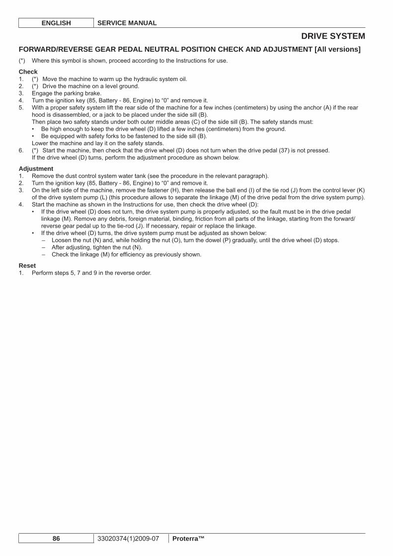
DRIVE SYSTEMENGLISH SERVICE MANUAL
86 33020374(1)2009-07 Proterra™
FORWARD/REVERSE GEAR PEDAL NEUTRAL POSITION CHECK AND ADJUSTMENT [All versions]Where this symbol is shown, proceed according to the Instructions for use.(*)
Check(*) Move the machine to warm up the hydraulic system oil.1. (*) Drive the machine on a level ground.2. Engage the parking brake.3. Turn the ignition key (85, Battery - 86, Engine) to “0” and remove it.4. With a proper safety system lift the rear side of the machine for a few inches (centimeters) by using the anchor (A) if the rear 5. hood is disassembled, or a jack to be placed under the side sill (B).Then place two safety stands under both outer middle areas (C) of the side sill (B). The safety stands must:
Be high enough to keep the drive wheel (D) lifted a few inches (centimeters) from the ground.• Be equipped with safety forks to be fastened to the side sill (B).•
Lower the machine and lay it on the safety stands.(*) Start the machine, then check that the drive wheel (D) does not turn when the drive pedal (37) is not pressed.6. If the drive wheel (D) turns, perform the adjustment procedure as shown below.
AdjustmentRemove the dust control system water tank (see the procedure in the relevant paragraph).1. Turn the ignition key (85, Battery - 86, Engine) to “0” and remove it.2. On the left side of the machine, remove the fastener (H), then release the ball end (I) of the tie rod (J) from the control lever (K) 3. of the drive system pump (L) (this procedure allows to separate the linkage (M) of the drive pedal from the drive system pump).Start the machine as shown in the Instructions for use, then check the drive wheel (D):4.
If the drive wheel (D) does not turn, the drive system pump is properly adjusted, so the fault must be in the drive pedal • linkage (M). Remove any debris, foreign material, binding, friction from all parts of the linkage, starting from the forward/reverse gear pedal up to the tie-rod (J). If necessary, repair or replace the linkage.If the drive wheel (D) turns, the drive system pump must be adjusted as shown below:•
Loosen the nut (N) and, while holding the nut (O), turn the dowel (P) gradually, until the drive wheel (D) stops. –After adjusting, tighten the nut (N). –Check the linkage (M) for effi ciency as previously shown. –
ResetPerform steps 5, 7 and 9 in the reverse order.1.
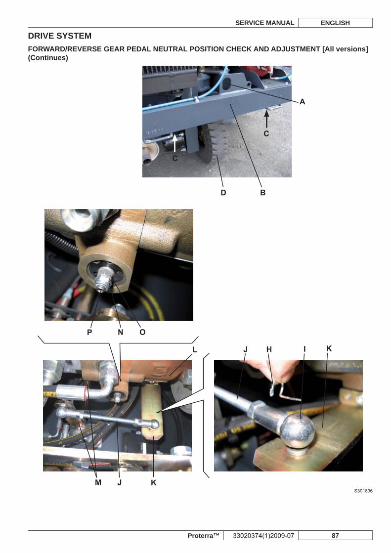
DRIVE SYSTEMSERVICE MANUAL ENGLISH
Proterra™ 33020374(1)2009-07 87
FORWARD/REVERSE GEAR PEDAL NEUTRAL POSITION CHECK AND ADJUSTMENT [All versions] (Continues)
S301836
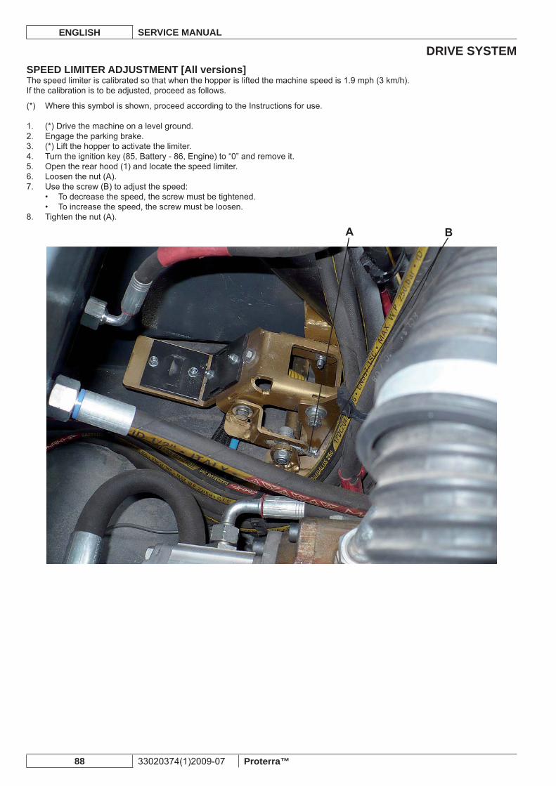
DRIVE SYSTEMENGLISH SERVICE MANUAL
88 33020374(1)2009-07 Proterra™
SPEED LIMITER ADJUSTMENT [All versions]The speed limiter is calibrated so that when the hopper is lifted the machine speed is 1.9 mph (3 km/h).If the calibration is to be adjusted, proceed as follows.
Where this symbol is shown, proceed according to the Instructions for use.(*)
(*) Drive the machine on a level ground.1. Engage the parking brake.2. (*) Lift the hopper to activate the limiter.3. Turn the ignition key (85, Battery - 86, Engine) to “0” and remove it.4. Open the rear hood (1) and locate the speed limiter.5. Loosen the nut (A).6. Use the screw (B) to adjust the speed: 7.
To decrease the speed, the screw must be tightened.• To increase the speed, the screw must be loosen.•
Tighten the nut (A).8.
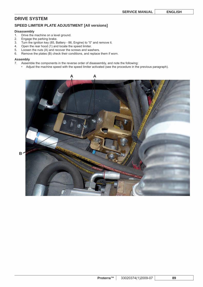
DRIVE SYSTEMSERVICE MANUAL ENGLISH
Proterra™ 33020374(1)2009-07 89
SPEED LIMITER PLATE ADJUSTMENT [All versions]Disassembly
Drive the machine on a level ground.1. Engage the parking brake.2. Turn the ignition key (85, Battery - 86, Engine) to “0” and remove it.3. Open the rear hood (1) and locate the speed limiter.4. Loosen the nuts (A) and recover the screws and washers.5. Remove the plates (B) check their conditions, and replace them if worn.6.
AssemblyAssemble the components in the reverse order of disassembly, and note the following:7.
Adjust the machine speed with the speed limiter activated (see the procedure in the previous paragraph).•
A
B
A
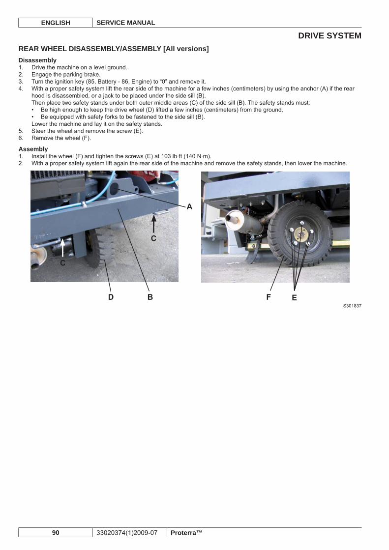
DRIVE SYSTEMENGLISH SERVICE MANUAL
90 33020374(1)2009-07 Proterra™
REAR WHEEL DISASSEMBLY/ASSEMBLY [All versions]Disassembly
Drive the machine on a level ground.1. Engage the parking brake.2. Turn the ignition key (85, Battery - 86, Engine) to “0” and remove it.3. With a proper safety system lift the rear side of the machine for a few inches (centimeters) by using the anchor (A) if the rear 4. hood is disassembled, or a jack to be placed under the side sill (B).Then place two safety stands under both outer middle areas (C) of the side sill (B). The safety stands must:
Be high enough to keep the drive wheel (D) lifted a few inches (centimeters) from the ground.• Be equipped with safety forks to be fastened to the side sill (B).•
Lower the machine and lay it on the safety stands.Steer the wheel and remove the screw (E).5. Remove the wheel (F).6.
AssemblyInstall the wheel (F) and tighten the screws (E) at 103 lb·ft (140 N·m).1. With a proper safety system lift again the rear side of the machine and remove the safety stands, then lower the machine.2.
S301837
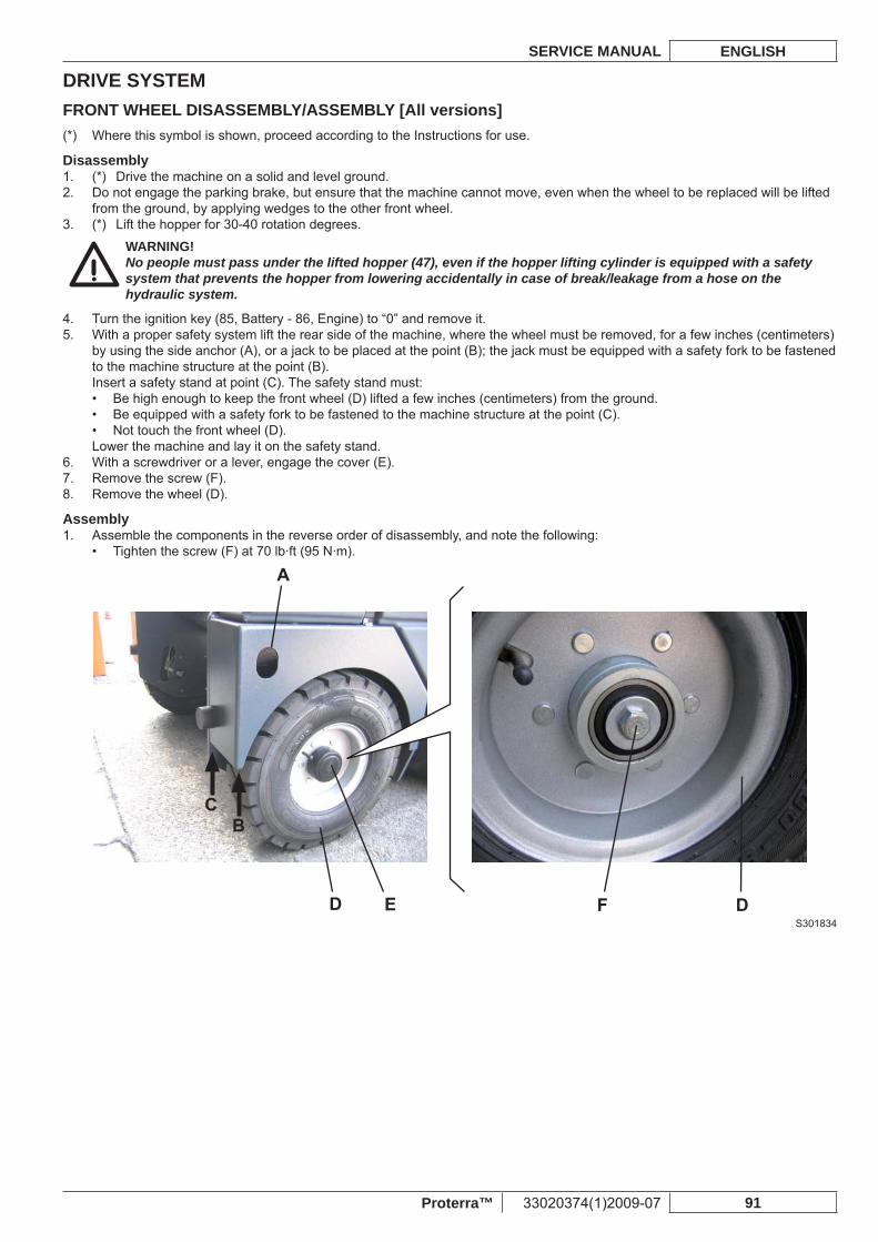
DRIVE SYSTEMSERVICE MANUAL ENGLISH
Proterra™ 33020374(1)2009-07 91
FRONT WHEEL DISASSEMBLY/ASSEMBLY [All versions]Where this symbol is shown, proceed according to the Instructions for use.(*)
Disassembly(*) Drive the machine on a solid and level ground.1. Do not engage the parking brake, but ensure that the machine cannot move, even when the wheel to be replaced will be lifted 2. from the ground, by applying wedges to the other front wheel.(*) Lift the hopper for 30-40 rotation degrees.3.
WARNING!No people must pass under the lifted hopper (47), even if the hopper lifting cylinder is equipped with a safety system that prevents the hopper from lowering accidentally in case of break/leakage from a hose on the hydraulic system.
Turn the ignition key (85, Battery - 86, Engine) to “0” and remove it.4. With a proper safety system lift the rear side of the machine, where the wheel must be removed, for a few inches (centimeters) 5. by using the side anchor (A), or a jack to be placed at the point (B); the jack must be equipped with a safety fork to be fastened to the machine structure at the point (B).Insert a safety stand at point (C). The safety stand must:
Be high enough to keep the front wheel (D) lifted a few inches (centimeters) from the ground.• Be equipped with a safety fork to be fastened to the machine structure at the point (C).• Not touch the front wheel (D).•
Lower the machine and lay it on the safety stand.With a screwdriver or a lever, engage the cover (E).6. Remove the screw (F).7. Remove the wheel (D).8.
AssemblyAssemble the components in the reverse order of disassembly, and note the following:1.
Tighten the screw (F) at 70 lb·ft (95 N·m).•
S301834
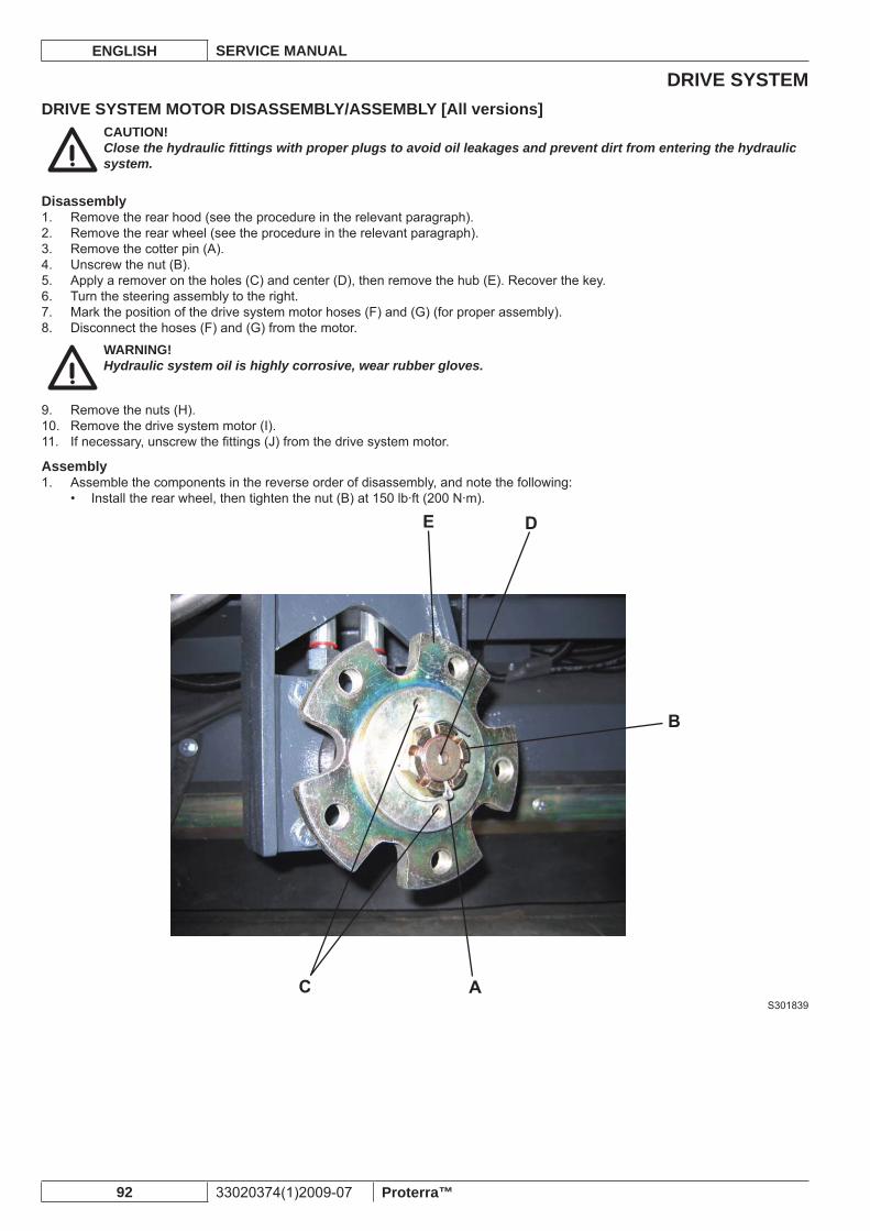
DRIVE SYSTEMENGLISH SERVICE MANUAL
92 33020374(1)2009-07 Proterra™
DRIVE SYSTEM MOTOR DISASSEMBLY/ASSEMBLY [All versions]CAUTION!Close the hydraulic fi ttings with proper plugs to avoid oil leakages and prevent dirt from entering the hydraulic system.
DisassemblyRemove the rear hood (see the procedure in the relevant paragraph).1. Remove the rear wheel (see the procedure in the relevant paragraph).2. Remove the cotter pin (A).3. Unscrew the nut (B).4. Apply a remover on the holes (C) and center (D), then remove the hub (E). Recover the key.5. Turn the steering assembly to the right.6. Mark the position of the drive system motor hoses (F) and (G) (for proper assembly).7. Disconnect the hoses (F) and (G) from the motor.8.
WARNING!Hydraulic system oil is highly corrosive, wear rubber gloves.
Remove the nuts (H).9. Remove the drive system motor (I).10. If necessary, unscrew the fi ttings (J) from the drive system motor.11.
AssemblyAssemble the components in the reverse order of disassembly, and note the following:1.
Install the rear wheel, then tighten the nut (B) at 150 lb·ft (200 N·m).•
S301839
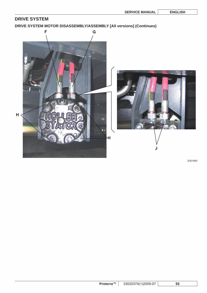
DRIVE SYSTEMSERVICE MANUAL ENGLISH
Proterra™ 33020374(1)2009-07 93
DRIVE SYSTEM MOTOR DISASSEMBLY/ASSEMBLY [All versions] (Continues)
S301840
DRIVE SYSTEMENGLISH SERVICE MANUAL
94 33020374(1)2009-07 Proterra™
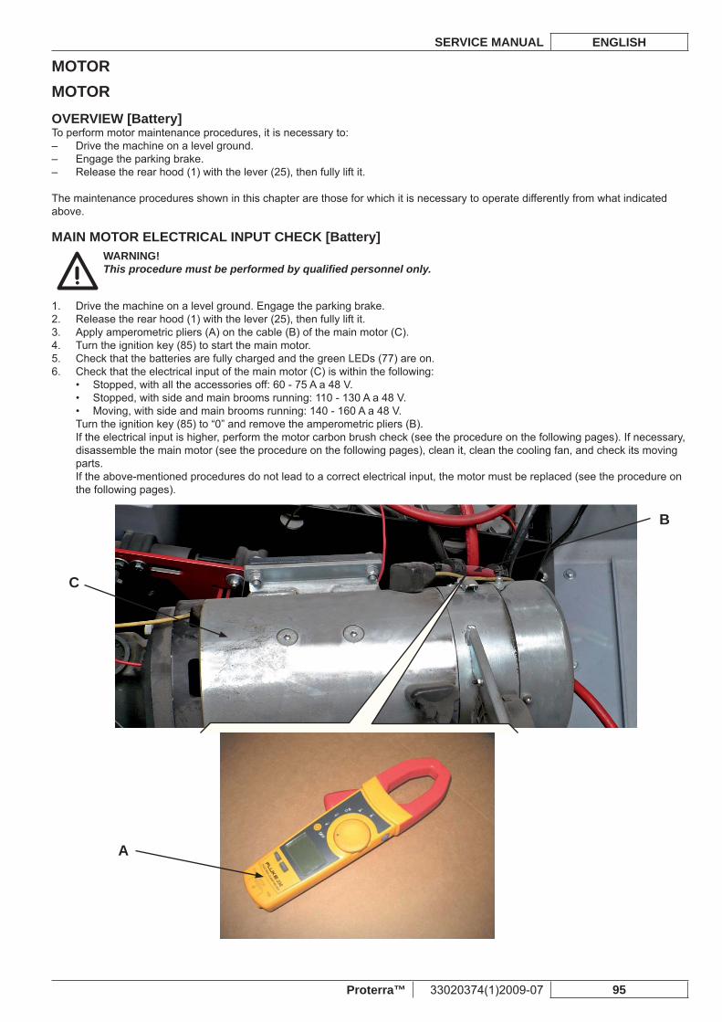
MOTORSERVICE MANUAL ENGLISH
Proterra™ 33020374(1)2009-07 95
MOTOROVERVIEW [Battery]To perform motor maintenance procedures, it is necessary to:
Drive the machine on a level ground. –Engage the parking brake. –Release the rear hood (1) with the lever (25), then fully lift it. –
The maintenance procedures shown in this chapter are those for which it is necessary to operate differently from what indicated above.
MAIN MOTOR ELECTRICAL INPUT CHECK [Battery]WARNING!This procedure must be performed by qualifi ed personnel only.
Drive the machine on a level ground. Engage the parking brake.1. Release the rear hood (1) with the lever (25), then fully lift it.2. Apply amperometric pliers (A) on the cable (B) of the main motor (C).3. Turn the ignition key (85) to start the main motor.4. Check that the batteries are fully charged and the green LEDs (77) are on.5. Check that the electrical input of the main motor (C) is within the following:6.
Stopped, with all the accessories off: 60 - 75 A a 48 V.• Stopped, with side and main brooms running: 110 - 130 A a 48 V.• Moving, with side and main brooms running: 140 - 160 A a 48 V.•
Turn the ignition key (85) to “0” and remove the amperometric pliers (B).If the electrical input is higher, perform the motor carbon brush check (see the procedure on the following pages). If necessary, disassemble the main motor (see the procedure on the following pages), clean it, clean the cooling fan, and check its moving parts.If the above-mentioned procedures do not lead to a correct electrical input, the motor must be replaced (see the procedure on the following pages).
A
C
B
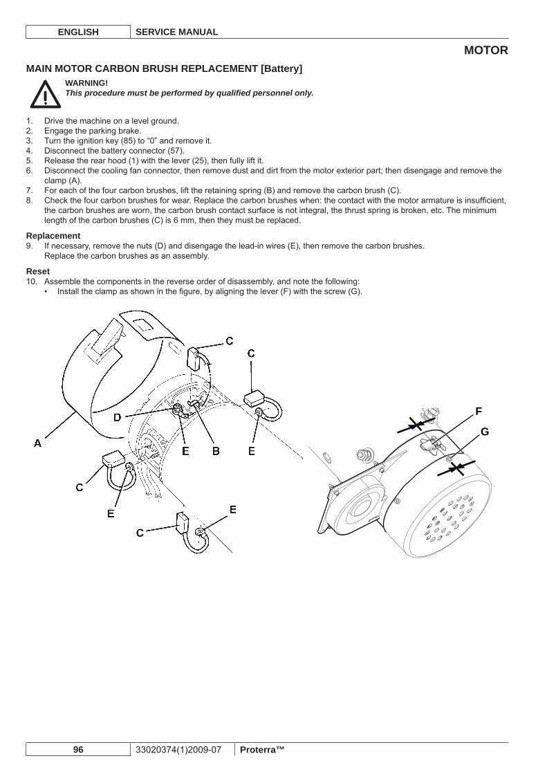
MOTORENGLISH SERVICE MANUAL
96 33020374(1)2009-07 Proterra™
MAIN MOTOR CARBON BRUSH REPLACEMENT [Battery]WARNING!This procedure must be performed by qualifi ed personnel only.
Drive the machine on a level ground. 1. Engage the parking brake.2. Turn the ignition key (85) to “0” and remove it.3. Disconnect the battery connector (57).4. Release the rear hood (1) with the lever (25), then fully lift it.5. Disconnect the cooling fan connector, then remove dust and dirt from the motor exterior part; then disengage and remove the 6. clamp (A).For each of the four carbon brushes, lift the retaining spring (B) and remove the carbon brush (C).7. Check the four carbon brushes for wear. Replace the carbon brushes when: the contact with the motor armature is insuffi cient, 8. the carbon brushes are worn, the carbon brush contact surface is not integral, the thrust spring is broken, etc. The minimum length of the carbon brushes (C) is 6 mm, then they must be replaced.
ReplacementIf necessary, remove the nuts (D) and disengage the lead-in wires (E), then remove the carbon brushes.9. Replace the carbon brushes as an assembly.
ResetAssemble the components in the reverse order of disassembly, and note the following:10.
Install the clamp as shown in the fi gure, by aligning the lever (F) with the screw (G).•
F
G
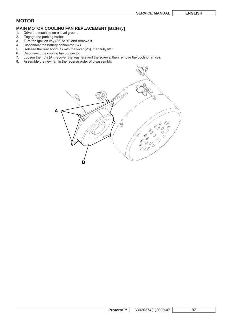
MOTORSERVICE MANUAL ENGLISH
Proterra™ 33020374(1)2009-07 97
MAIN MOTOR COOLING FAN REPLACEMENT [Battery]Drive the machine on a level ground. 1. Engage the parking brake.2. Turn the ignition key (85) to “0” and remove it.3. Disconnect the battery connector (57).4. Release the rear hood (1) with the lever (25), then fully lift it.5. Disconnect the cooling fan connector.6. Loosen the nuts (A), recover the washers and the screws, then remove the cooling fan (B).7. Assemble the new fan in the reverse order of disassembly. 8.
A
B
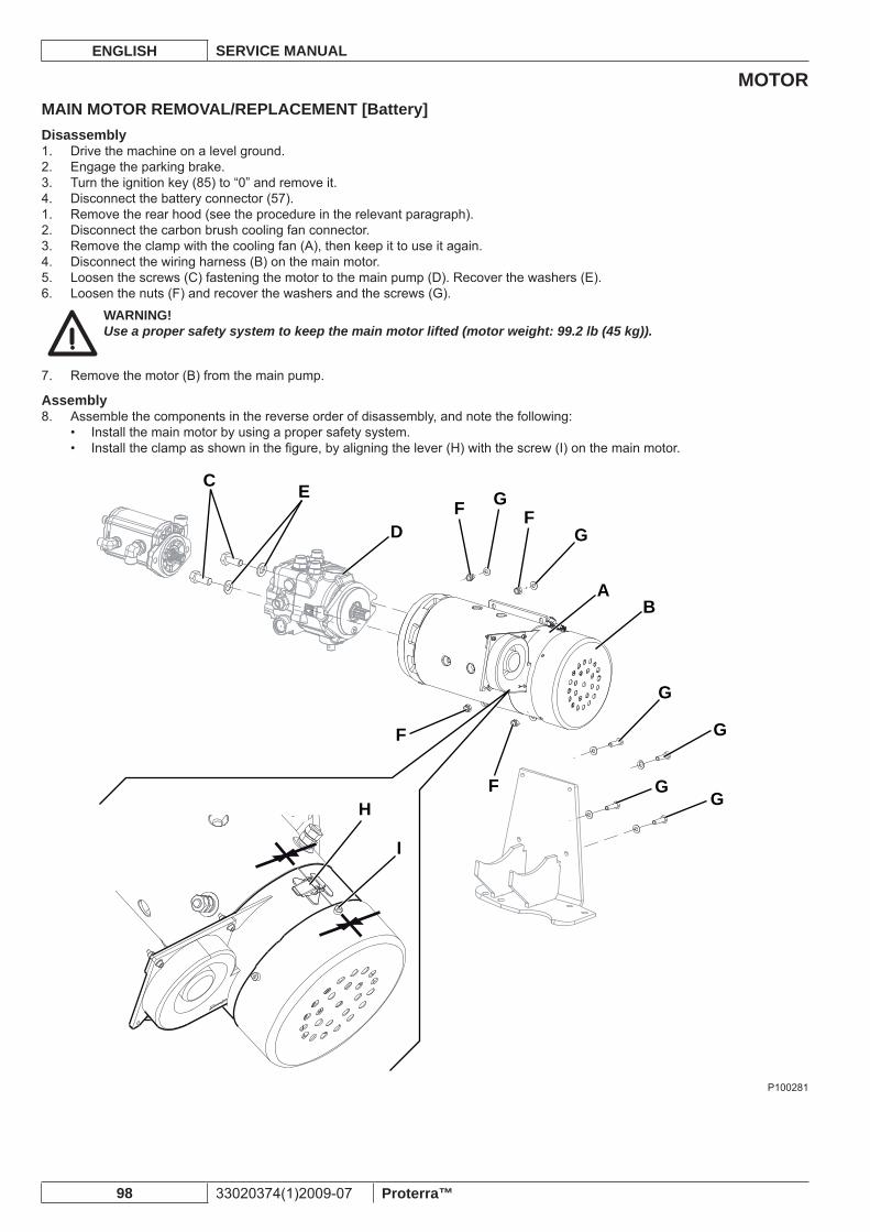
MOTORENGLISH SERVICE MANUAL
98 33020374(1)2009-07 Proterra™
MAIN MOTOR REMOVAL/REPLACEMENT [Battery]Disassembly
Drive the machine on a level ground. 1. Engage the parking brake.2. Turn the ignition key (85) to “0” and remove it.3. Disconnect the battery connector (57).4. Remove the rear hood (see the procedure in the relevant paragraph).1. Disconnect the carbon brush cooling fan connector.2. Remove the clamp with the cooling fan (A), then keep it to use it again.3. Disconnect the wiring harness (B) on the main motor.4. Loosen the screws (C) fastening the motor to the main pump (D). Recover the washers (E).5. Loosen the nuts (F) and recover the washers and the screws (G).6.
WARNING!Use a proper safety system to keep the main motor lifted (motor weight: 99.2 lb (45 kg)).
Remove the motor (B) from the main pump.7.
AssemblyAssemble the components in the reverse order of disassembly, and note the following:8.
Install the main motor by using a proper safety system.• Install the clamp as shown in the fi gure, by aligning the lever (H) with the screw (I) on the main motor.•
AB
C
DF
F
F
FG
G
G
G
GG
E
H
I
P100281
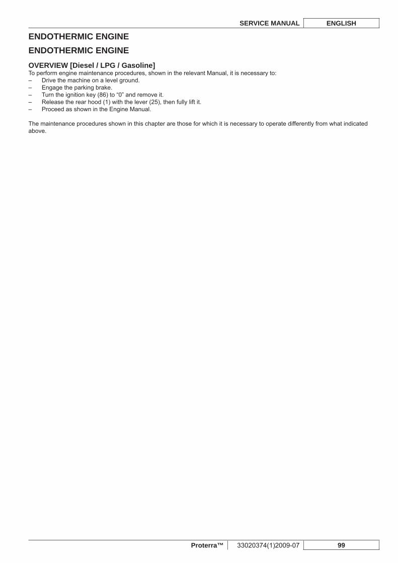
ENDOTHERMIC ENGINESERVICE MANUAL ENGLISH
Proterra™ 33020374(1)2009-07 99
ENDOTHERMIC ENGINEOVERVIEW [Diesel / LPG / Gasoline]To perform engine maintenance procedures, shown in the relevant Manual, it is necessary to:
Drive the machine on a level ground. –Engage the parking brake. –Turn the ignition key (86) to “0” and remove it. –Release the rear hood (1) with the lever (25), then fully lift it. –Proceed as shown in the Engine Manual. –
The maintenance procedures shown in this chapter are those for which it is necessary to operate differently from what indicated above.
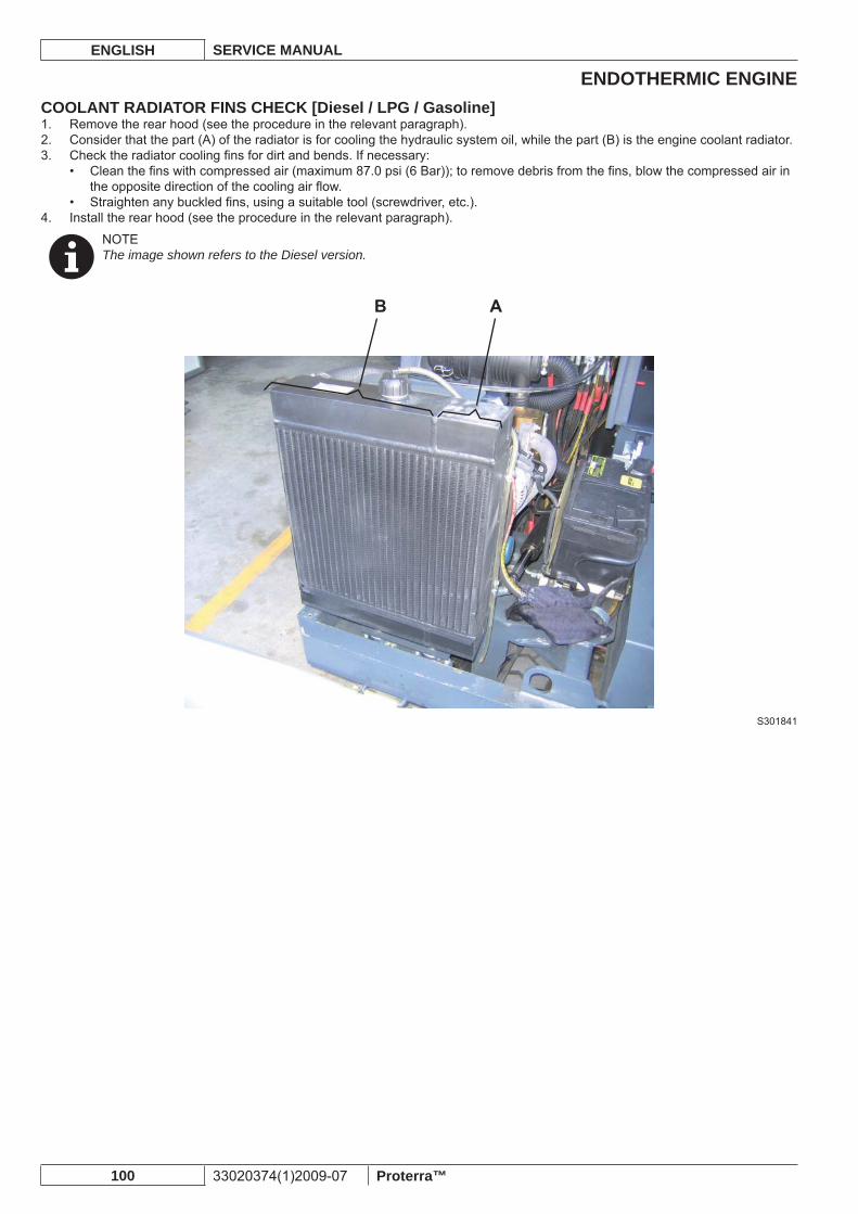
ENDOTHERMIC ENGINEENGLISH SERVICE MANUAL
100 33020374(1)2009-07 Proterra™
COOLANT RADIATOR FINS CHECK [Diesel / LPG / Gasoline]Remove the rear hood (see the procedure in the relevant paragraph).1. Consider that the part (A) of the radiator is for cooling the hydraulic system oil, while the part (B) is the engine coolant radiator.2. Check the radiator cooling fi ns for dirt and bends. If necessary:3.
Clean the fi ns with compressed air (maximum 87.0 psi (6 Bar)); to remove debris from the fi ns, blow the compressed air in • the opposite direction of the cooling air fl ow.Straighten any buckled fi ns, using a suitable tool (screwdriver, etc.).•
Install the rear hood (see the procedure in the relevant paragraph).4.
NOTEThe image shown refers to the Diesel version.
S301841
ENDOTHERMIC ENGINESERVICE MANUAL ENGLISH
Proterra™ 33020374(1)2009-07 101
AIR FILTER DISASSEMBLY/ASSEMBLY [Diesel / LPG / Gasoline]Disassembly
Remove the dust control system water tank (see the procedure in the relevant paragraph).1. Loosen the clamps (A) and disconnect the hoses (B) from the air fi lter assembly (C).2. Remove the two screws (D), then remove the air fi lter assembly (C).3.
AssemblyAssemble the components in the reverse order of disassembly.1.
NOTEThe image shown refers to the Diesel version.
S301842
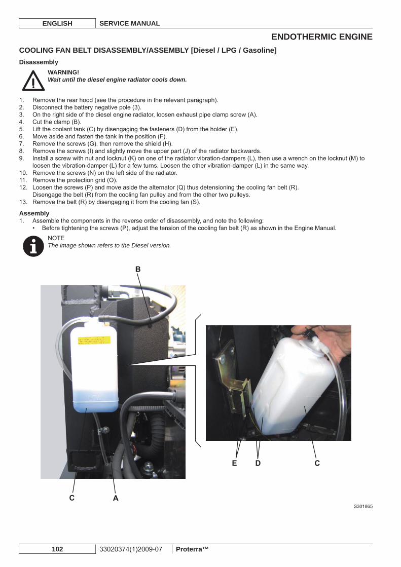
ENDOTHERMIC ENGINEENGLISH SERVICE MANUAL
102 33020374(1)2009-07 Proterra™
COOLING FAN BELT DISASSEMBLY/ASSEMBLY [Diesel / LPG / Gasoline]Disassembly
WARNING!Wait until the diesel engine radiator cools down.
Remove the rear hood (see the procedure in the relevant paragraph).1. Disconnect the battery negative pole (3).2. On the right side of the diesel engine radiator, loosen exhaust pipe clamp screw (A).3. Cut the clamp (B).4. Lift the coolant tank (C) by disengaging the fasteners (D) from the holder (E).5. Move aside and fasten the tank in the position (F).6. Remove the screws (G), then remove the shield (H).7. Remove the screws (I) and slightly move the upper part (J) of the radiator backwards.8. Install a screw with nut and locknut (K) on one of the radiator vibration-dampers (L), then use a wrench on the locknut (M) to 9. loosen the vibration-damper (L) for a few turns. Loosen the other vibration-damper (L) in the same way.Remove the screws (N) on the left side of the radiator.10. Remove the protection grid (O).11. Loosen the screws (P) and move aside the alternator (Q) thus detensioning the cooling fan belt (R).12. Disengage the belt (R) from the cooling fan pulley and from the other two pulleys.Remove the belt (R) by disengaging it from the cooling fan (S).13.
AssemblyAssemble the components in the reverse order of disassembly, and note the following:1.
Before tightening the screws (P), adjust the tension of the cooling fan belt (R) as shown in the Engine Manual.•
NOTEThe image shown refers to the Diesel version.
S301865
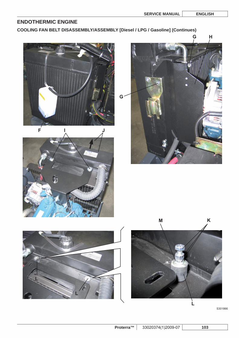
ENDOTHERMIC ENGINESERVICE MANUAL ENGLISH
Proterra™ 33020374(1)2009-07 103
COOLING FAN BELT DISASSEMBLY/ASSEMBLY [Diesel / LPG / Gasoline] (Continues)
S301866
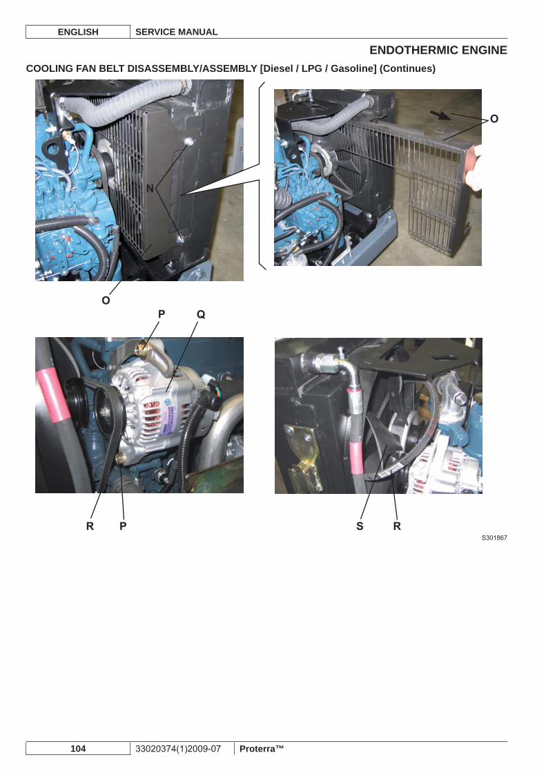
ENDOTHERMIC ENGINEENGLISH SERVICE MANUAL
104 33020374(1)2009-07 Proterra™
COOLING FAN BELT DISASSEMBLY/ASSEMBLY [Diesel / LPG / Gasoline] (Continues)
S301867
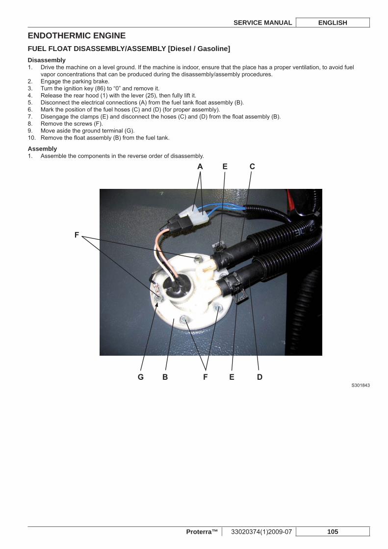
ENDOTHERMIC ENGINESERVICE MANUAL ENGLISH
Proterra™ 33020374(1)2009-07 105
FUEL FLOAT DISASSEMBLY/ASSEMBLY [Diesel / Gasoline]Disassembly
Drive the machine on a level ground. If the machine is indoor, ensure that the place has a proper ventilation, to avoid fuel 1. vapor concentrations that can be produced during the disassembly/assembly procedures.Engage the parking brake.2. Turn the ignition key (86) to “0” and remove it.3. Release the rear hood (1) with the lever (25), then fully lift it.4. Disconnect the electrical connections (A) from the fuel tank fl oat assembly (B).5. Mark the position of the fuel hoses (C) and (D) (for proper assembly).6. Disengage the clamps (E) and disconnect the hoses (C) and (D) from the fl oat assembly (B).7. Remove the screws (F).8. Move aside the ground terminal (G).9. Remove the fl oat assembly (B) from the fuel tank.10.
AssemblyAssemble the components in the reverse order of disassembly.1.
S301843

ENDOTHERMIC ENGINEENGLISH SERVICE MANUAL
106 33020374(1)2009-07 Proterra™
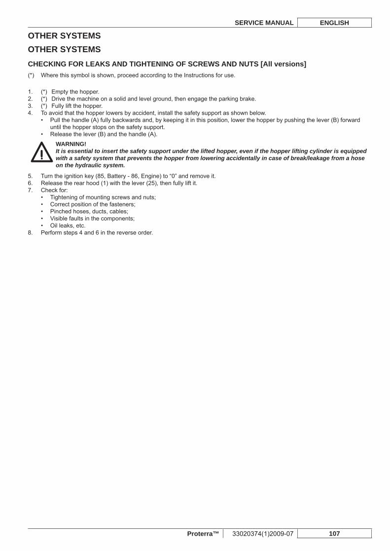
OTHER SYSTEMSSERVICE MANUAL ENGLISH
Proterra™ 33020374(1)2009-07 107
OTHER SYSTEMSCHECKING FOR LEAKS AND TIGHTENING OF SCREWS AND NUTS [All versions]
Where this symbol is shown, proceed according to the Instructions for use.(*)
(*) Empty the hopper.1. (*) Drive the machine on a solid and level ground, then engage the parking brake.2. (*) Fully lift the hopper.3. To avoid that the hopper lowers by accident, install the safety support as shown below.4.
Pull the handle (A) fully backwards and, by keeping it in this position, lower the hopper by pushing the lever (B) forward • until the hopper stops on the safety support.Release the lever (B) and the handle (A).•
WARNING!It is essential to insert the safety support under the lifted hopper, even if the hopper lifting cylinder is equipped with a safety system that prevents the hopper from lowering accidentally in case of break/leakage from a hose on the hydraulic system.
Turn the ignition key (85, Battery - 86, Engine) to “0” and remove it.5. Release the rear hood (1) with the lever (25), then fully lift it.6. Check for:7.
Tightening of mounting screws and nuts;• Correct position of the fasteners;• Pinched hoses, ducts, cables;• Visible faults in the components;• Oil leaks, etc.•
Perform steps 4 and 6 in the reverse order.8.
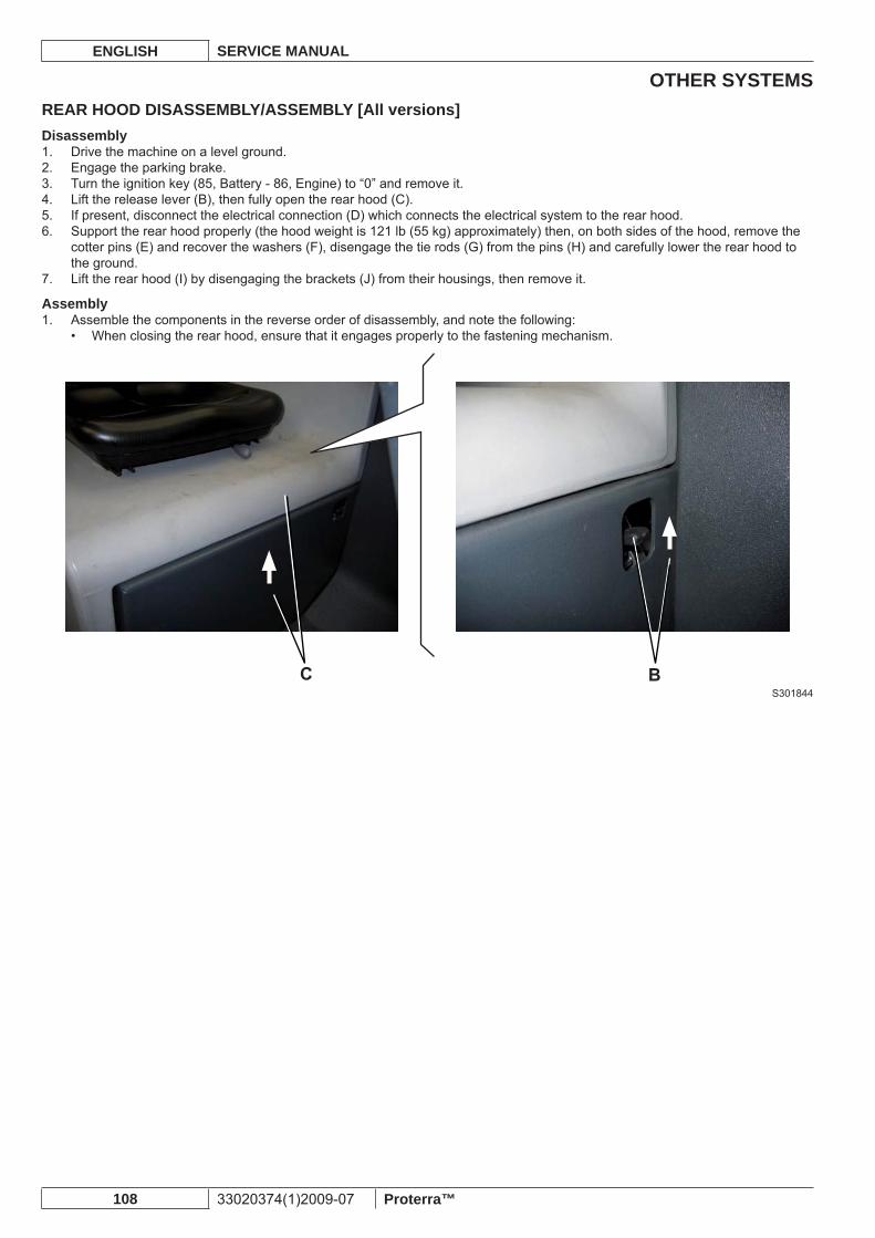
OTHER SYSTEMSENGLISH SERVICE MANUAL
108 33020374(1)2009-07 Proterra™
REAR HOOD DISASSEMBLY/ASSEMBLY [All versions]Disassembly
Drive the machine on a level ground.1. Engage the parking brake.2. Turn the ignition key (85, Battery - 86, Engine) to “0” and remove it.3. Lift the release lever (B), then fully open the rear hood (C).4. If present, disconnect the electrical connection (D) which connects the electrical system to the rear hood.5. Support the rear hood properly (the hood weight is 121 lb (55 kg) approximately) then, on both sides of the hood, remove the 6. cotter pins (E) and recover the washers (F), disengage the tie rods (G) from the pins (H) and carefully lower the rear hood to the ground.Lift the rear hood (I) by disengaging the brackets (J) from their housings, then remove it.7.
AssemblyAssemble the components in the reverse order of disassembly, and note the following:1.
When closing the rear hood, ensure that it engages properly to the fastening mechanism.•
S301844
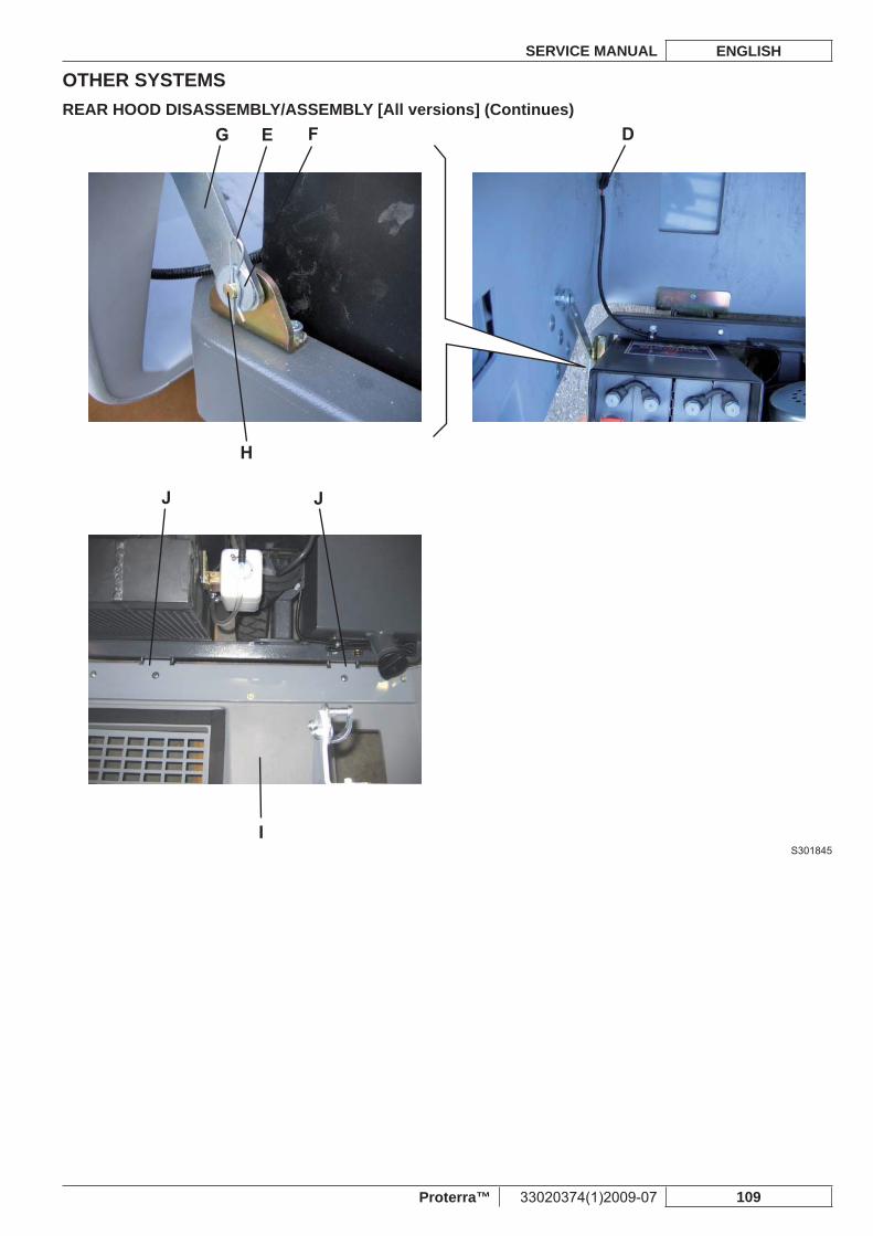
OTHER SYSTEMSSERVICE MANUAL ENGLISH
Proterra™ 33020374(1)2009-07 109
REAR HOOD DISASSEMBLY/ASSEMBLY [All versions] (Continues)
S301845
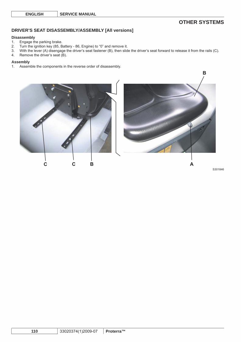
OTHER SYSTEMSENGLISH SERVICE MANUAL
110 33020374(1)2009-07 Proterra™
DRIVER’S SEAT DISASSEMBLY/ASSEMBLY [All versions]Disassembly
Engage the parking brake.1. Turn the ignition key (85, Battery - 86, Engine) to “0” and remove it.2. With the lever (A) disengage the driver’s seat fastener (B), then slide the driver’s seat forward to release it from the rails (C).3. Remove the driver’s seat (B).4.
AssemblyAssemble the components in the reverse order of disassembly.1.
S301846
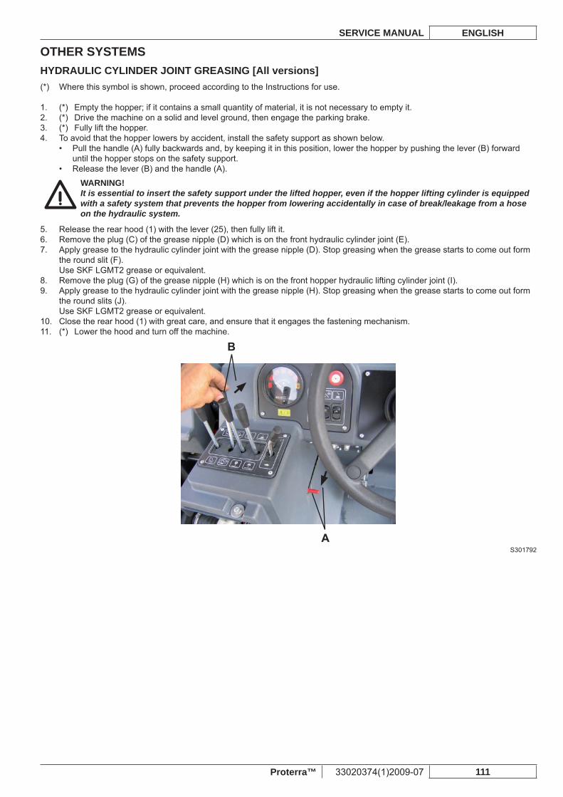
OTHER SYSTEMSSERVICE MANUAL ENGLISH
Proterra™ 33020374(1)2009-07 111
HYDRAULIC CYLINDER JOINT GREASING [All versions]Where this symbol is shown, proceed according to the Instructions for use.(*)
(*) Empty the hopper; if it contains a small quantity of material, it is not necessary to empty it.1. (*) Drive the machine on a solid and level ground, then engage the parking brake.2. (*) Fully lift the hopper.3. To avoid that the hopper lowers by accident, install the safety support as shown below.4.
Pull the handle (A) fully backwards and, by keeping it in this position, lower the hopper by pushing the lever (B) forward • until the hopper stops on the safety support.Release the lever (B) and the handle (A).•
WARNING!It is essential to insert the safety support under the lifted hopper, even if the hopper lifting cylinder is equipped with a safety system that prevents the hopper from lowering accidentally in case of break/leakage from a hose on the hydraulic system.
Release the rear hood (1) with the lever (25), then fully lift it.5. Remove the plug (C) of the grease nipple (D) which is on the front hydraulic cylinder joint (E).6. Apply grease to the hydraulic cylinder joint with the grease nipple (D). Stop greasing when the grease starts to come out form 7. the round slit (F).Use SKF LGMT2 grease or equivalent.Remove the plug (G) of the grease nipple (H) which is on the front hopper hydraulic lifting cylinder joint (I).8. Apply grease to the hydraulic cylinder joint with the grease nipple (H). Stop greasing when the grease starts to come out form 9. the round slits (J).Use SKF LGMT2 grease or equivalent.Close the rear hood (1) with great care, and ensure that it engages the fastening mechanism.10. (*) Lower the hood and turn off the machine.11.
S301792
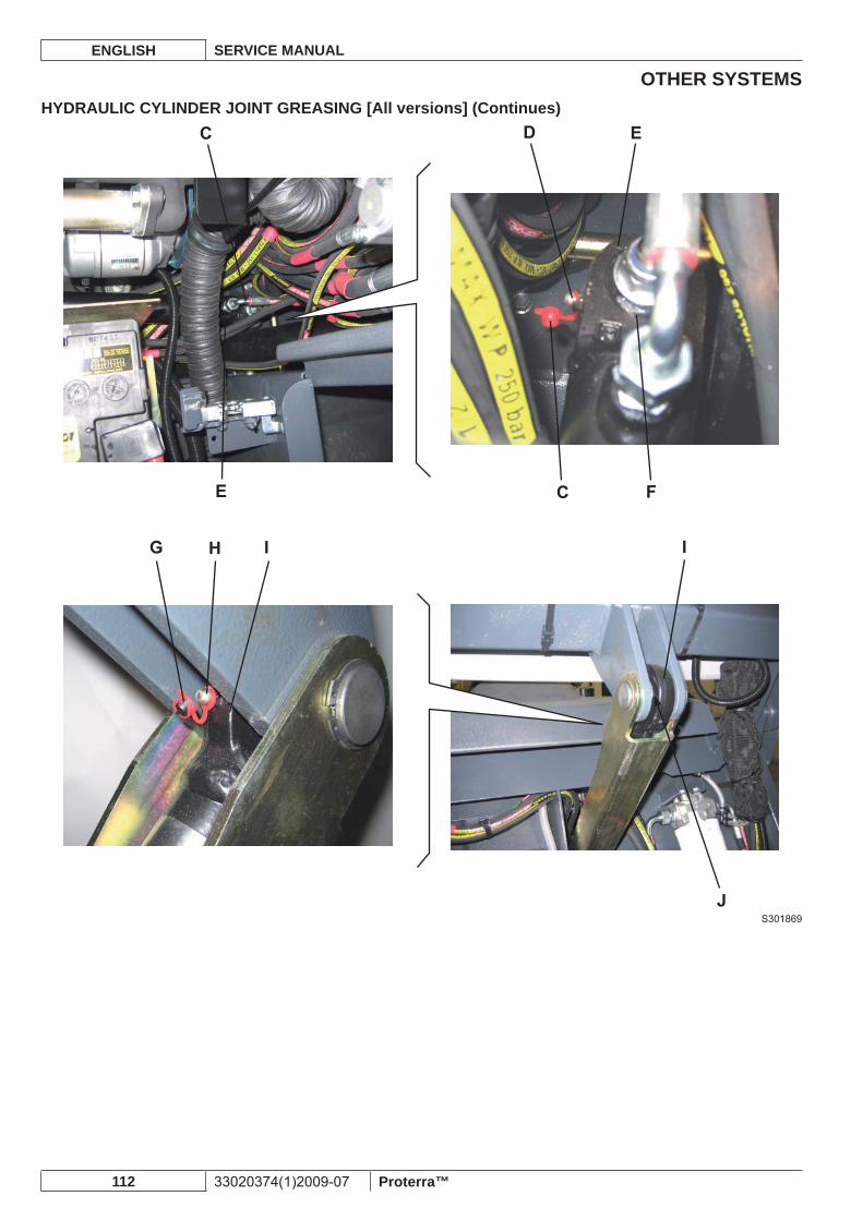
OTHER SYSTEMSENGLISH SERVICE MANUAL
112 33020374(1)2009-07 Proterra™
HYDRAULIC CYLINDER JOINT GREASING [All versions] (Continues)
S301869
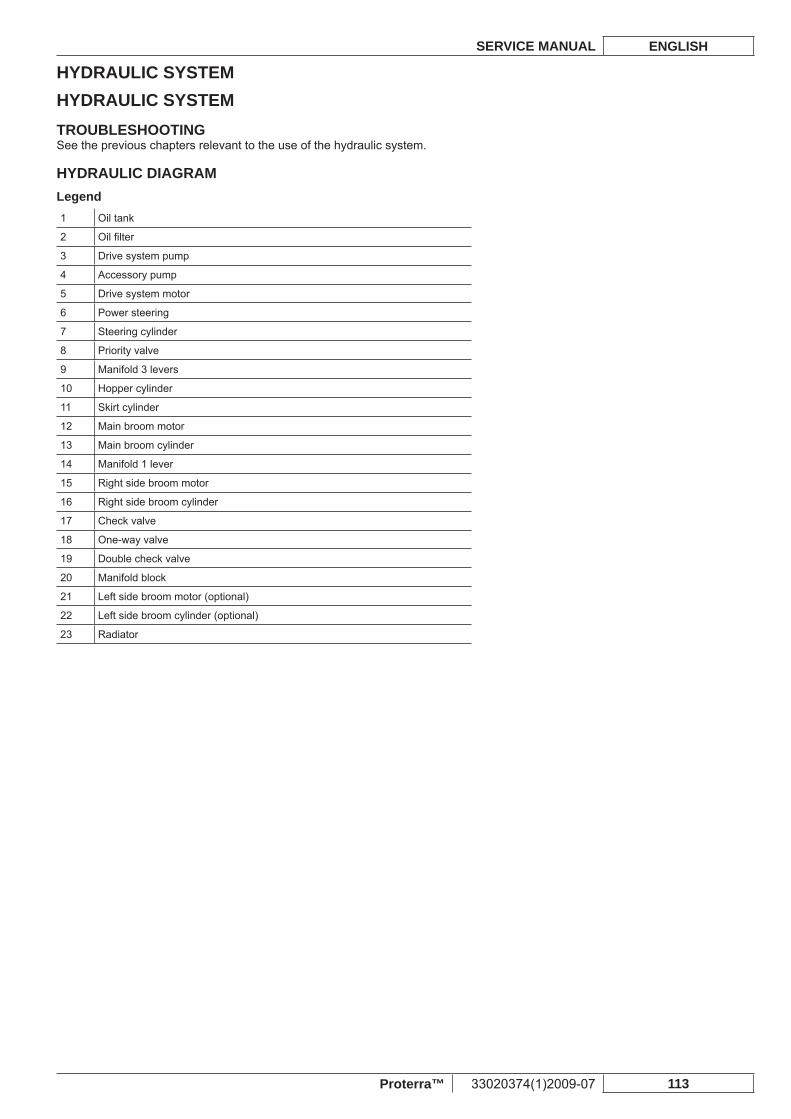
HYDRAULIC SYSTEMSERVICE MANUAL ENGLISH
Proterra™ 33020374(1)2009-07 113
HYDRAULIC SYSTEMTROUBLESHOOTINGSee the previous chapters relevant to the use of the hydraulic system.
HYDRAULIC DIAGRAMLegend1 Oil tank
2 Oil fi lter
3 Drive system pump
4 Accessory pump
5 Drive system motor
6 Power steering
7 Steering cylinder
8 Priority valve
9 Manifold 3 levers
10 Hopper cylinder
11 Skirt cylinder
12 Main broom motor
13 Main broom cylinder
14 Manifold 1 lever
15 Right side broom motor
16 Right side broom cylinder
17 Check valve
18 One-way valve
19 Double check valve
20 Manifold block
21 Left side broom motor (optional)
22 Left side broom cylinder (optional)
23 Radiator
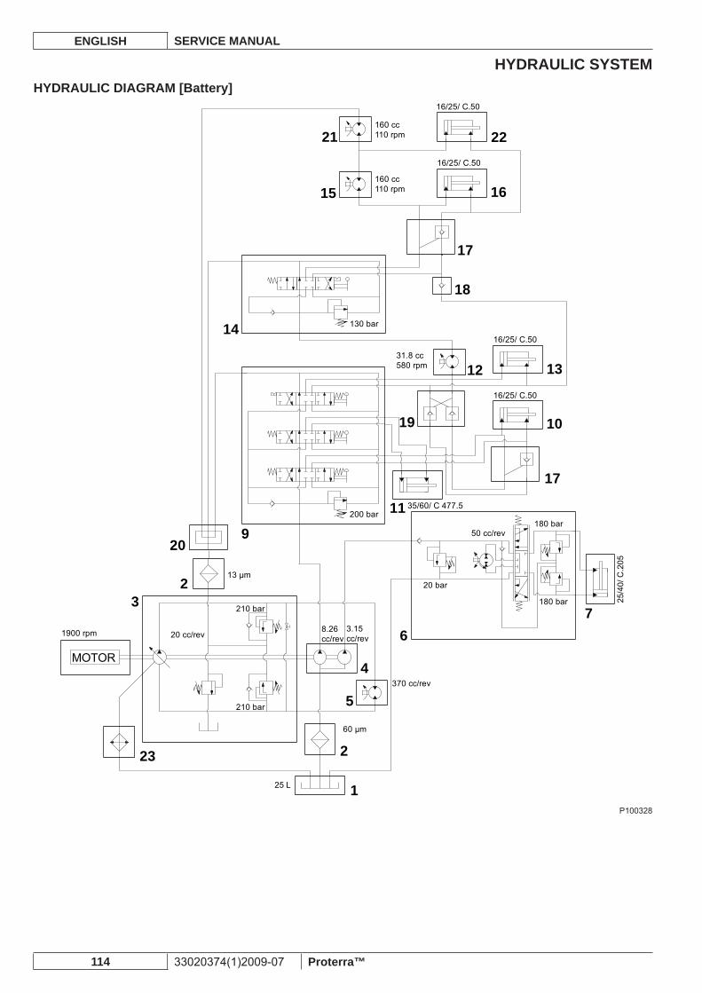
HYDRAULIC SYSTEMENGLISH SERVICE MANUAL
114 33020374(1)2009-07 Proterra™
HYDRAULIC DIAGRAM [Battery]
10
13
17
17
18
16
22
15
21
14
12
19
11
67
1
2
5
4
2
209
23
3
MOTOR
16/25/ C.50
160 cc110 rpm
160 cc110 rpm
31.8 cc580 rpm
130 bar
200 bar
16/25/ C.50
16/25/ C.50
16/25/ C.50
35/60/ C 477.5
370 cc/rev
50 cc/rev180 bar
180 bar
20 bar
3.15cc/rev
8.26cc/rev20 cc/rev1900 rpm
210 bar
210 bar
60 μm
13 μm
25 L
25/4
0/ C
.205
P100328
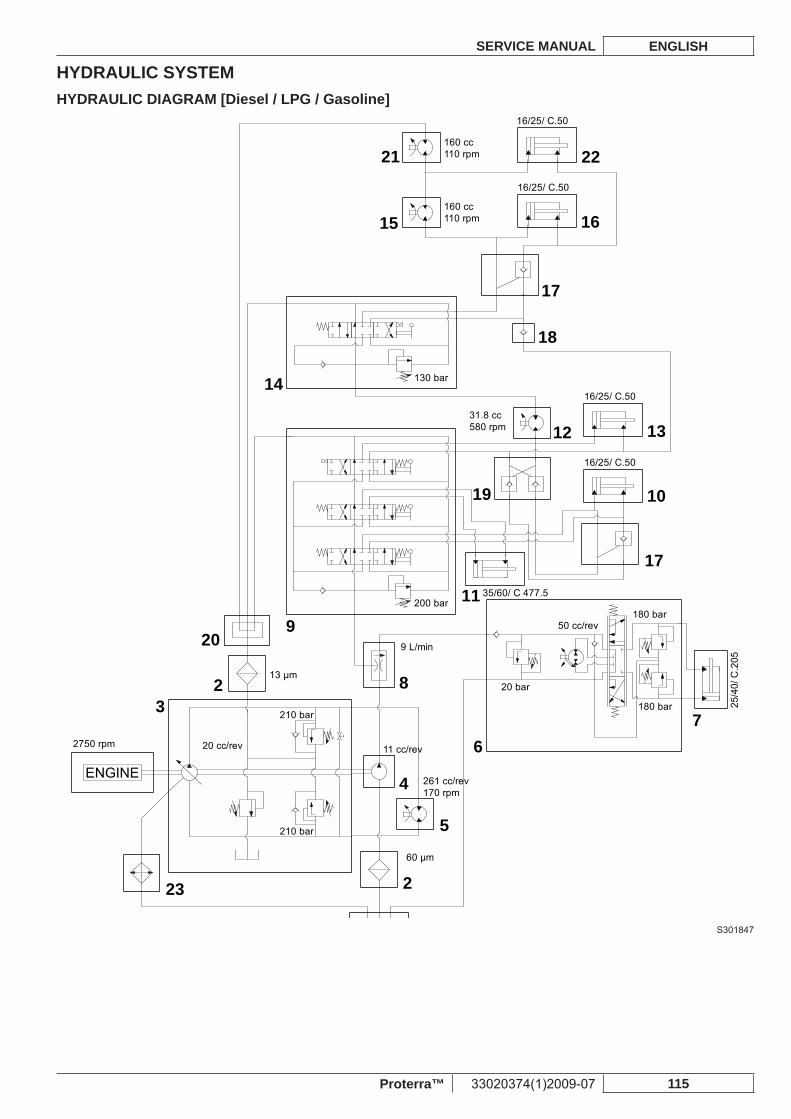
HYDRAULIC SYSTEMSERVICE MANUAL ENGLISH
Proterra™ 33020374(1)2009-07 115
HYDRAULIC DIAGRAM [Diesel / LPG / Gasoline]
10
13
17
17
18
16
22
15
21
14
12
19
11
67
2
5
4
82
209
23
3
ENGINE
16/25/ C.50
160 cc110 rpm
160 cc110 rpm
31.8 cc580 rpm
130 bar
200 bar
16/25/ C.50
16/25/ C.50
16/25/ C.50
35/60/ C 477.5
261 cc/rev170 rpm
50 cc/rev180 bar
180 bar
20 bar
9 L/min
11 cc/rev20 cc/rev2750 rpm
210 bar
210 bar
60 μm
13 μm
25/4
0/ C
.205
S301847
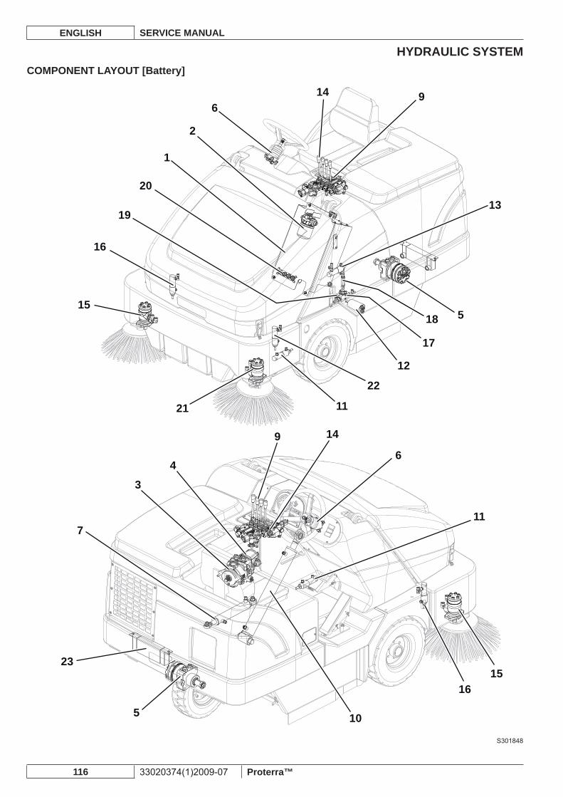
HYDRAULIC SYSTEMENGLISH SERVICE MANUAL
116 33020374(1)2009-07 Proterra™
COMPONENT LAYOUT [Battery]
13
12
3
23
17
18
6
6
9
11
11
22
21
16
16
10
15
15
14
149
1
4
5
5
20
19
2
7
S301848
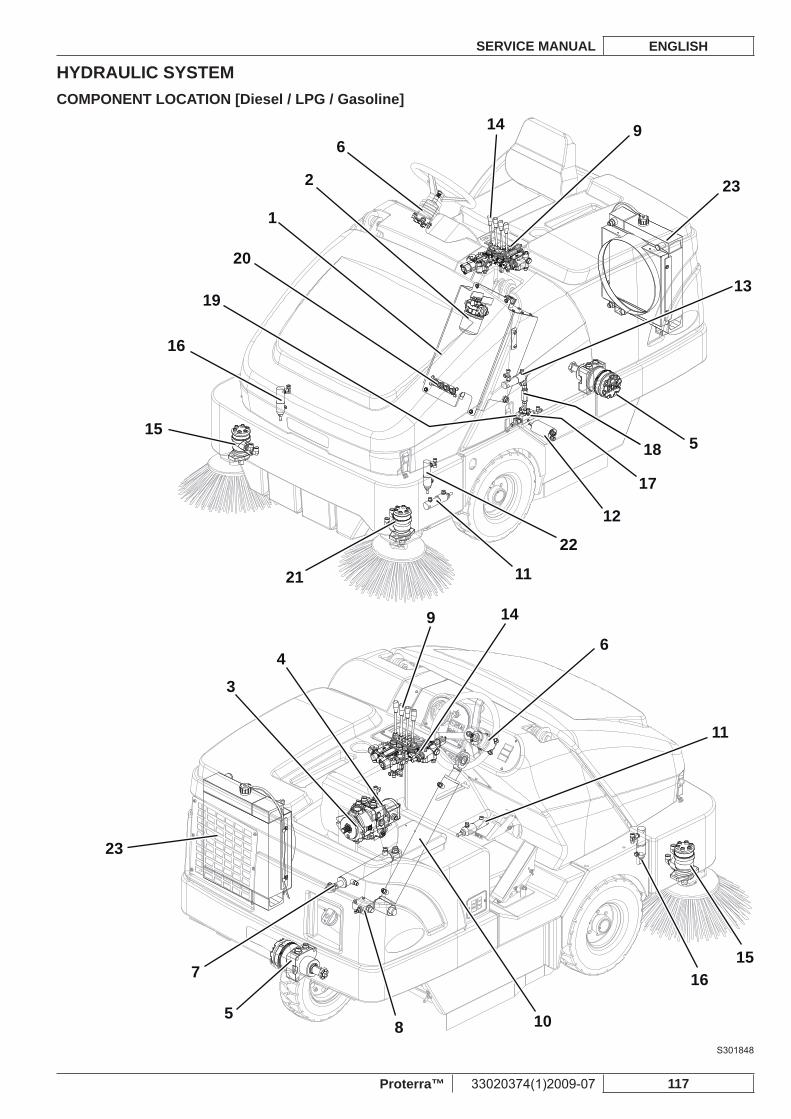
HYDRAULIC SYSTEMSERVICE MANUAL ENGLISH
Proterra™ 33020374(1)2009-07 117
COMPONENT LOCATION [Diesel / LPG / Gasoline]
13
12
3
8
23
23
17
18
6
6
9
11
11
22
21
16
16
10
15
15
14
149
1
4
5
5
20
19
2
7
S301848
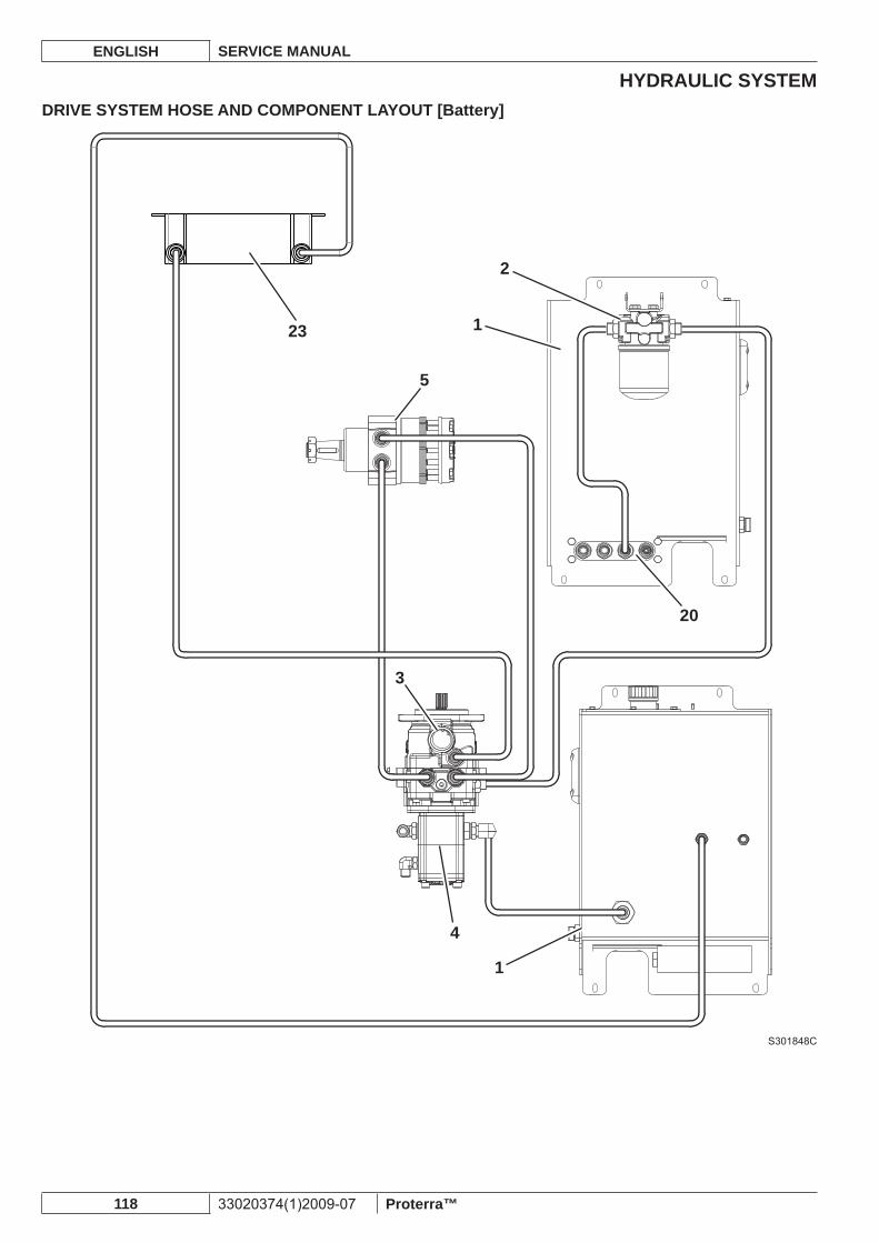
HYDRAULIC SYSTEMENGLISH SERVICE MANUAL
118 33020374(1)2009-07 Proterra™
DRIVE SYSTEM HOSE AND COMPONENT LAYOUT [Battery]
1
2
20
1
4
3
5
23
S301848C
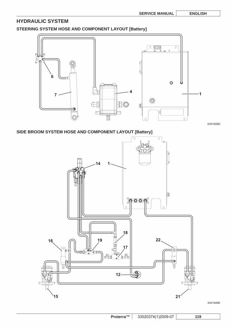
HYDRAULIC SYSTEMSERVICE MANUAL ENGLISH
Proterra™ 33020374(1)2009-07 119
STEERING SYSTEM HOSE AND COMPONENT LAYOUT [Battery]
1
6
74
S301848D
SIDE BROOM SYSTEM HOSE AND COMPONENT LAYOUT [Battery]
22
114
17
18
1916
12
2115S301848E
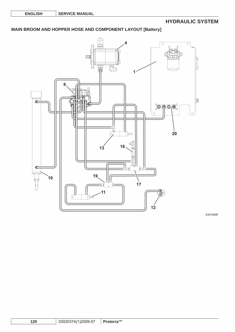
HYDRAULIC SYSTEMENGLISH SERVICE MANUAL
120 33020374(1)2009-07 Proterra™
MAIN BROOM AND HOPPER HOSE AND COMPONENT LAYOUT [Battery]
20
1
4
10
12
19
13 18
17
11
9
S301848F
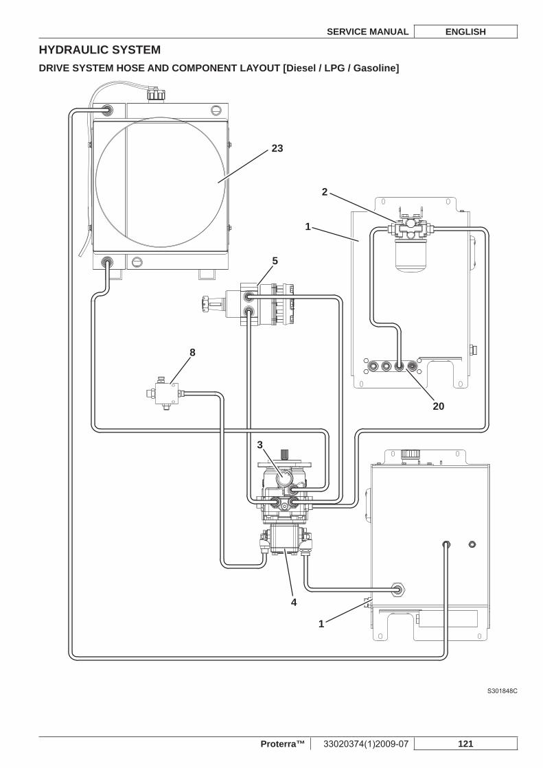
HYDRAULIC SYSTEMSERVICE MANUAL ENGLISH
Proterra™ 33020374(1)2009-07 121
DRIVE SYSTEM HOSE AND COMPONENT LAYOUT [Diesel / LPG / Gasoline]
1
2
20
1
4
3
8
5
23
S301848C
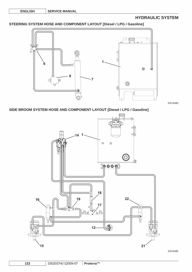
HYDRAULIC SYSTEMENGLISH SERVICE MANUAL
122 33020374(1)2009-07 Proterra™
STEERING SYSTEM HOSE AND COMPONENT LAYOUT [Diesel / LPG / Gasoline]
16
78
S301848D
SIDE BROOM SYSTEM HOSE AND COMPONENT LAYOUT [Diesel / LPG / Gasoline]
22
114
17
18
1916
12
2115S301848E
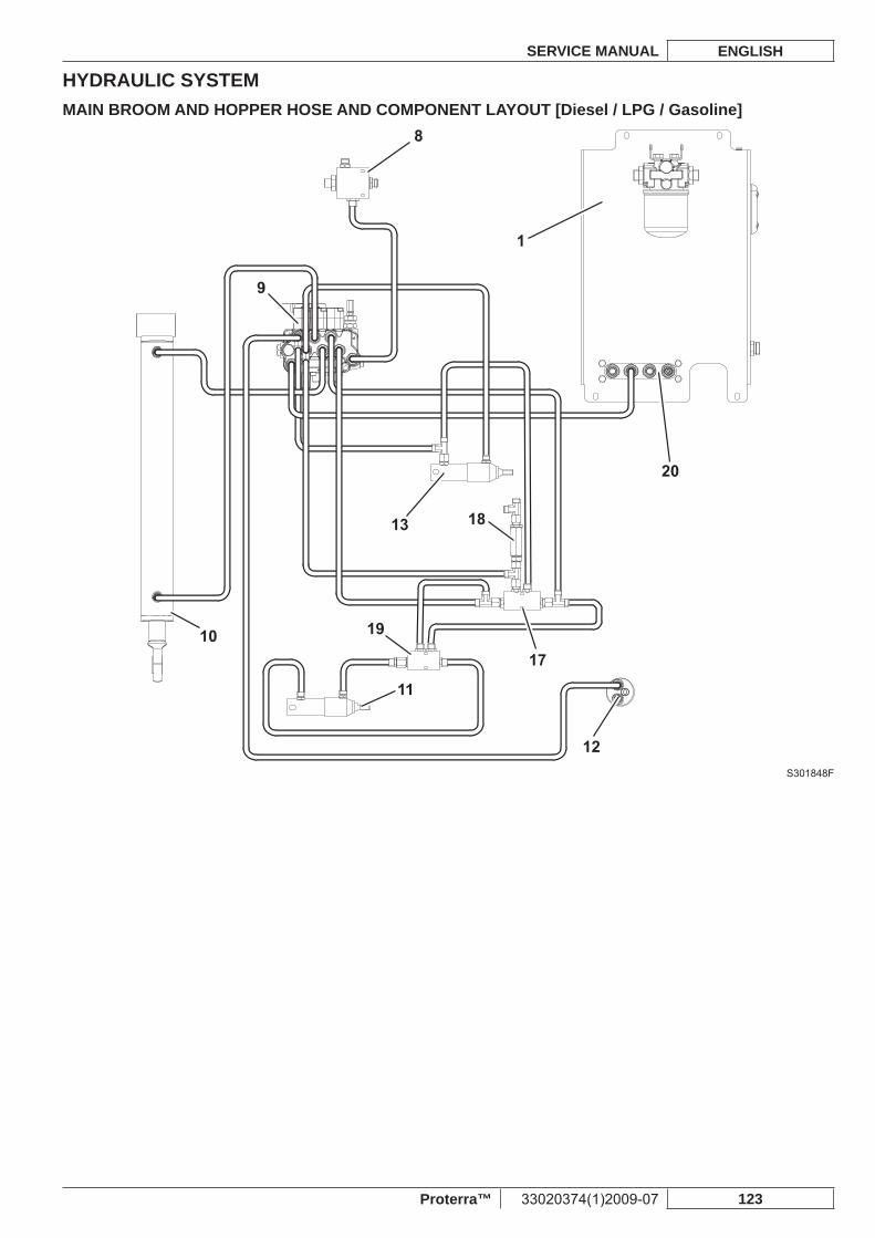
HYDRAULIC SYSTEMSERVICE MANUAL ENGLISH
Proterra™ 33020374(1)2009-07 123
MAIN BROOM AND HOPPER HOSE AND COMPONENT LAYOUT [Diesel / LPG / Gasoline]
20
1
8
10
12
19
13 18
17
11
9
S301848F
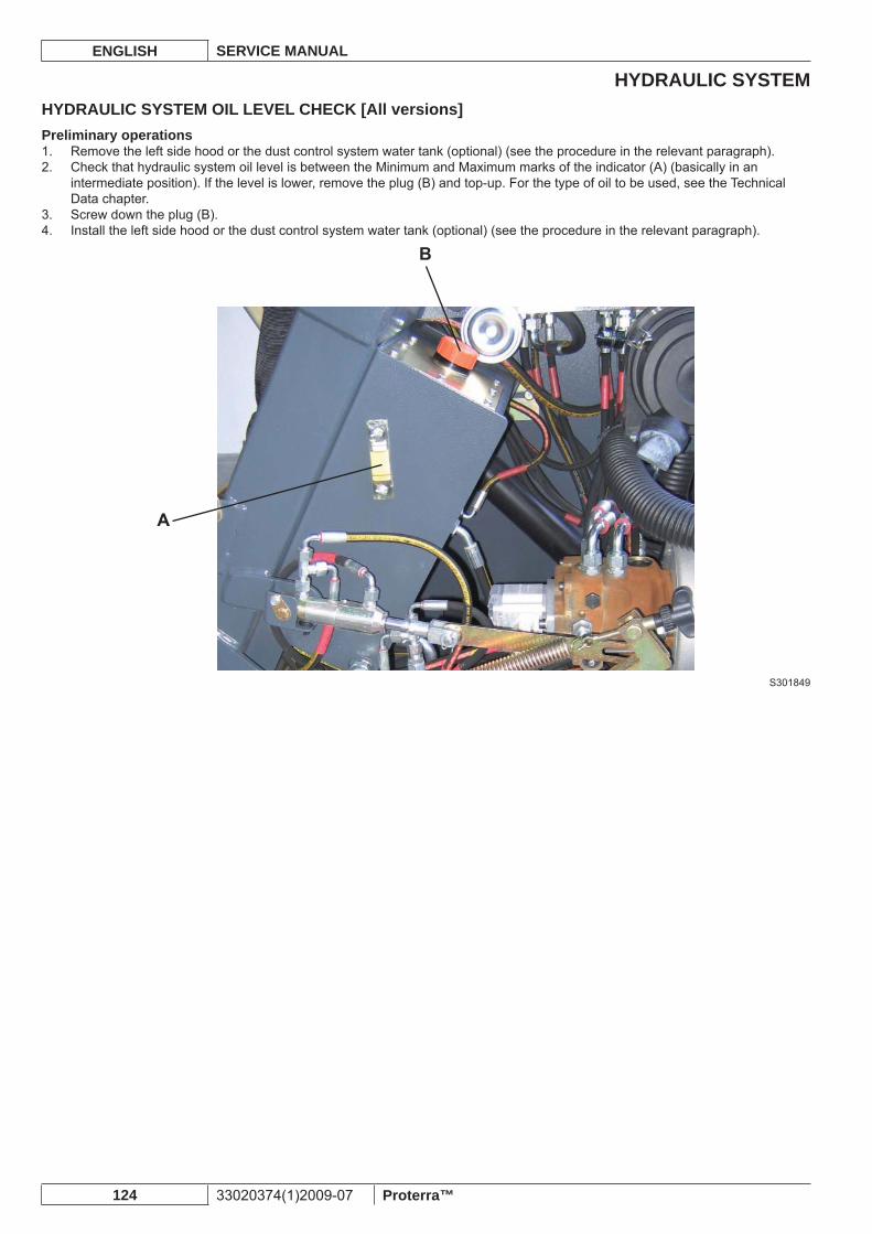
HYDRAULIC SYSTEMENGLISH SERVICE MANUAL
124 33020374(1)2009-07 Proterra™
HYDRAULIC SYSTEM OIL LEVEL CHECK [All versions]Preliminary operations
Remove the left side hood or the dust control system water tank (optional) (see the procedure in the relevant paragraph).1. Check that hydraulic system oil level is between the Minimum and Maximum marks of the indicator (A) (basically in an 2. intermediate position). If the level is lower, remove the plug (B) and top-up. For the type of oil to be used, see the Technical Data chapter.Screw down the plug (B).3. Install the left side hood or the dust control system water tank (optional) (see the procedure in the relevant paragraph).4.
S301849
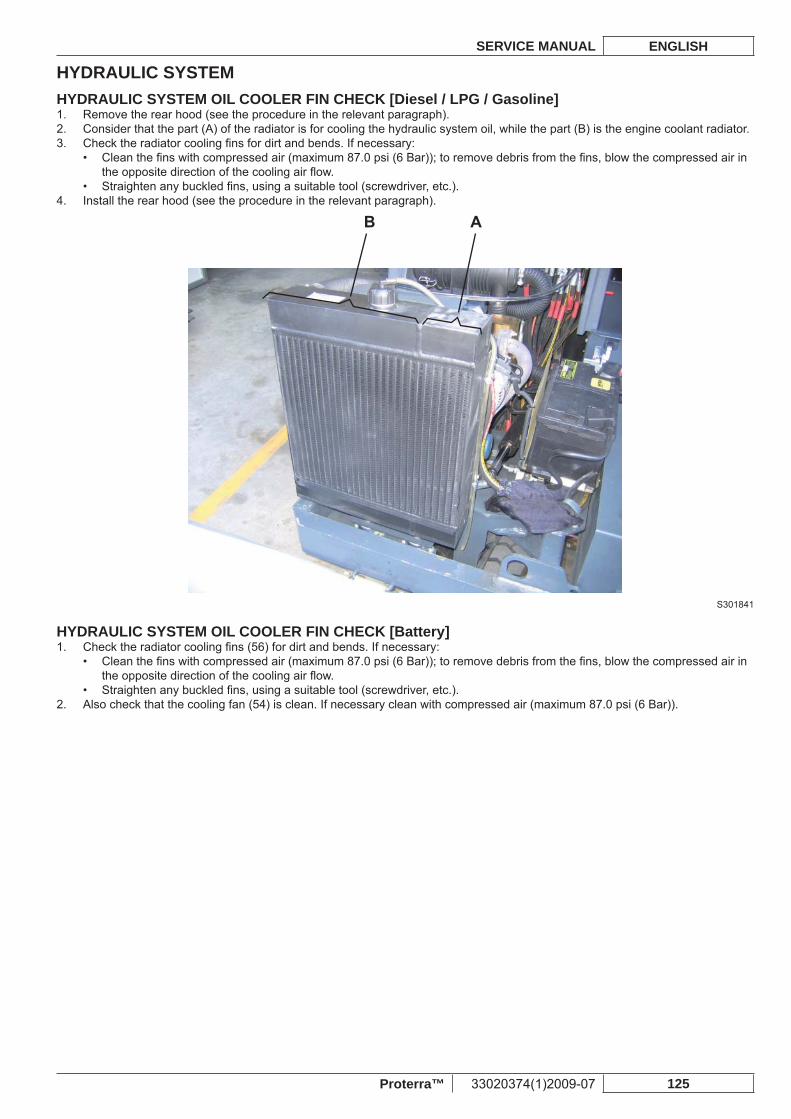
HYDRAULIC SYSTEMSERVICE MANUAL ENGLISH
Proterra™ 33020374(1)2009-07 125
HYDRAULIC SYSTEM OIL COOLER FIN CHECK [Diesel / LPG / Gasoline]Remove the rear hood (see the procedure in the relevant paragraph).1. Consider that the part (A) of the radiator is for cooling the hydraulic system oil, while the part (B) is the engine coolant radiator.2. Check the radiator cooling fi ns for dirt and bends. If necessary:3.
Clean the fi ns with compressed air (maximum 87.0 psi (6 Bar)); to remove debris from the fi ns, blow the compressed air in • the opposite direction of the cooling air fl ow.Straighten any buckled fi ns, using a suitable tool (screwdriver, etc.).•
Install the rear hood (see the procedure in the relevant paragraph).4.
S301841
HYDRAULIC SYSTEM OIL COOLER FIN CHECK [Battery]Check the radiator cooling fi ns (56) for dirt and bends. If necessary:1.
Clean the fi ns with compressed air (maximum 87.0 psi (6 Bar)); to remove debris from the fi ns, blow the compressed air in • the opposite direction of the cooling air fl ow.Straighten any buckled fi ns, using a suitable tool (screwdriver, etc.).•
Also check that the cooling fan (54) is clean. If necessary clean with compressed air (maximum 87.0 psi (6 Bar)).2.
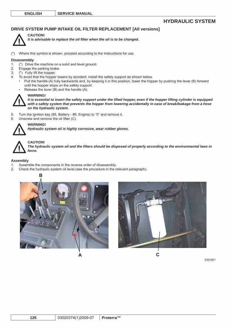
HYDRAULIC SYSTEMENGLISH SERVICE MANUAL
126 33020374(1)2009-07 Proterra™
DRIVE SYSTEM PUMP INTAKE OIL FILTER REPLACEMENT [All versions]CAUTION!It is advisable to replace the oil fi lter when the oil is to be changed.
Where this symbol is shown, proceed according to the Instructions for use.(*)
Disassembly(*) Drive the machine on a solid and level ground.1. Engage the parking brake.2. (*) Fully lift the hopper.3. To avoid that the hopper lowers by accident, install the safety support as shown below.4.
Pull the handle (A) fully backwards and, by keeping it in this position, lower the hopper by pushing the lever (B) forward • until the hopper stops on the safety support.Release the lever (B) and the handle (A).•
WARNING!It is essential to insert the safety support under the lifted hopper, even if the hopper lifting cylinder is equipped with a safety system that prevents the hopper from lowering accidentally in case of break/leakage from a hose on the hydraulic system.
Turn the ignition key (85, Battery - 86, Engine) to “0” and remove it.5. Unscrew and remove the oil fi lter (C).6.
WARNING!Hydraulic system oil is highly corrosive, wear rubber gloves.
CAUTION!The hydraulic system oil and the fi lters should be disposed of properly according to the environmental laws in force.
AssemblyAssemble the components in the reverse order of disassembly.1. Check the hydraulic system oil level (see the procedure in the relevant paragraph).2.
S301851
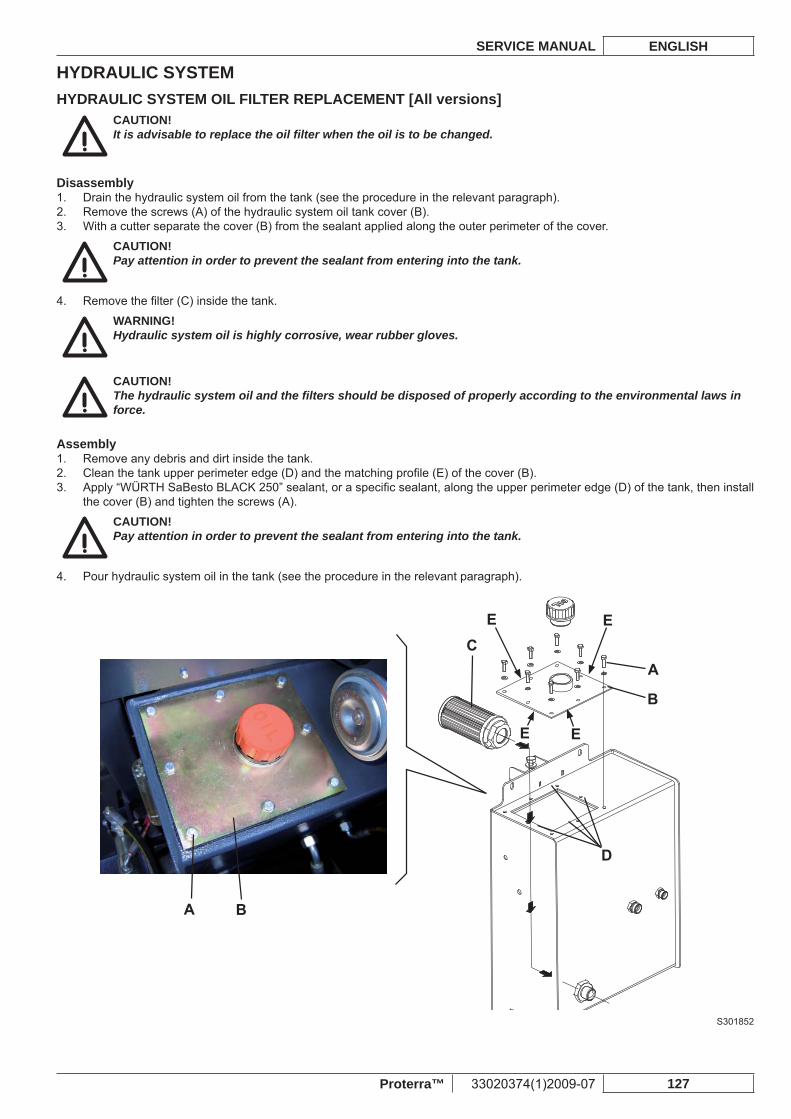
HYDRAULIC SYSTEMSERVICE MANUAL ENGLISH
Proterra™ 33020374(1)2009-07 127
HYDRAULIC SYSTEM OIL FILTER REPLACEMENT [All versions]CAUTION!It is advisable to replace the oil fi lter when the oil is to be changed.
DisassemblyDrain the hydraulic system oil from the tank (see the procedure in the relevant paragraph).1. Remove the screws (A) of the hydraulic system oil tank cover (B).2. With a cutter separate the cover (B) from the sealant applied along the outer perimeter of the cover.3.
CAUTION!Pay attention in order to prevent the sealant from entering into the tank.
Remove the fi lter (C) inside the tank.4.
WARNING!Hydraulic system oil is highly corrosive, wear rubber gloves.
CAUTION!The hydraulic system oil and the fi lters should be disposed of properly according to the environmental laws in force.
AssemblyRemove any debris and dirt inside the tank.1. Clean the tank upper perimeter edge (D) and the matching profi le (E) of the cover (B).2. Apply “WÜRTH SaBesto BLACK 250” sealant, or a specifi c sealant, along the upper perimeter edge (D) of the tank, then install 3. the cover (B) and tighten the screws (A).
CAUTION!Pay attention in order to prevent the sealant from entering into the tank.
Pour hydraulic system oil in the tank (see the procedure in the relevant paragraph).4.
S301852
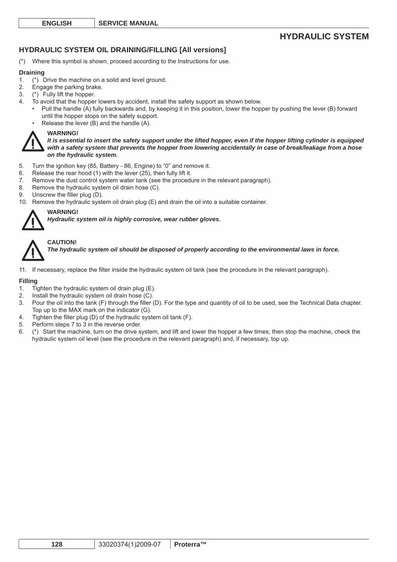
HYDRAULIC SYSTEMENGLISH SERVICE MANUAL
128 33020374(1)2009-07 Proterra™
HYDRAULIC SYSTEM OIL DRAINING/FILLING [All versions]Where this symbol is shown, proceed according to the Instructions for use.(*)
Draining(*) Drive the machine on a solid and level ground.1. Engage the parking brake.2. (*) Fully lift the hopper.3. To avoid that the hopper lowers by accident, install the safety support as shown below.4.
Pull the handle (A) fully backwards and, by keeping it in this position, lower the hopper by pushing the lever (B) forward • until the hopper stops on the safety support.Release the lever (B) and the handle (A).•
WARNING!It is essential to insert the safety support under the lifted hopper, even if the hopper lifting cylinder is equipped with a safety system that prevents the hopper from lowering accidentally in case of break/leakage from a hose on the hydraulic system.
Turn the ignition key (85, Battery - 86, Engine) to “0” and remove it.5. Release the rear hood (1) with the lever (25), then fully lift it.6. Remove the dust control system water tank (see the procedure in the relevant paragraph).7. Remove the hydraulic system oil drain hose (C).8. Unscrew the fi ller plug (D).9. Remove the hydraulic system oil drain plug (E) and drain the oil into a suitable container.10.
WARNING!Hydraulic system oil is highly corrosive, wear rubber gloves.
CAUTION!The hydraulic system oil should be disposed of properly according to the environmental laws in force.
If necessary, replace the fi lter inside the hydraulic system oil tank (see the procedure in the relevant paragraph).11.
FillingTighten the hydraulic system oil drain plug (E).1. Install the hydraulic system oil drain hose (C).2. Pour the oil into the tank (F) through the fi ller (D). For the type and quantity of oil to be used, see the Technical Data chapter.3. Top up to the MAX mark on the indicator (G).Tighten the fi ller plug (D) of the hydraulic system oil tank (F).4. Perform steps 7 to 3 in the reverse order.5. (*) Start the machine, turn on the drive system, and lift and lower the hopper a few times; then stop the machine, check the 6. hydraulic system oil level (see the procedure in the relevant paragraph) and, if necessary, top up.
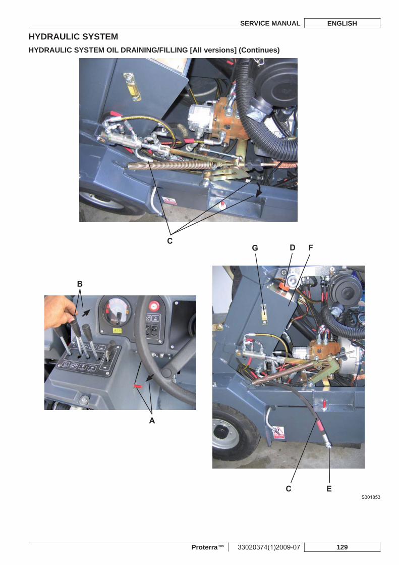
HYDRAULIC SYSTEMSERVICE MANUAL ENGLISH
Proterra™ 33020374(1)2009-07 129
HYDRAULIC SYSTEM OIL DRAINING/FILLING [All versions] (Continues)
S301853
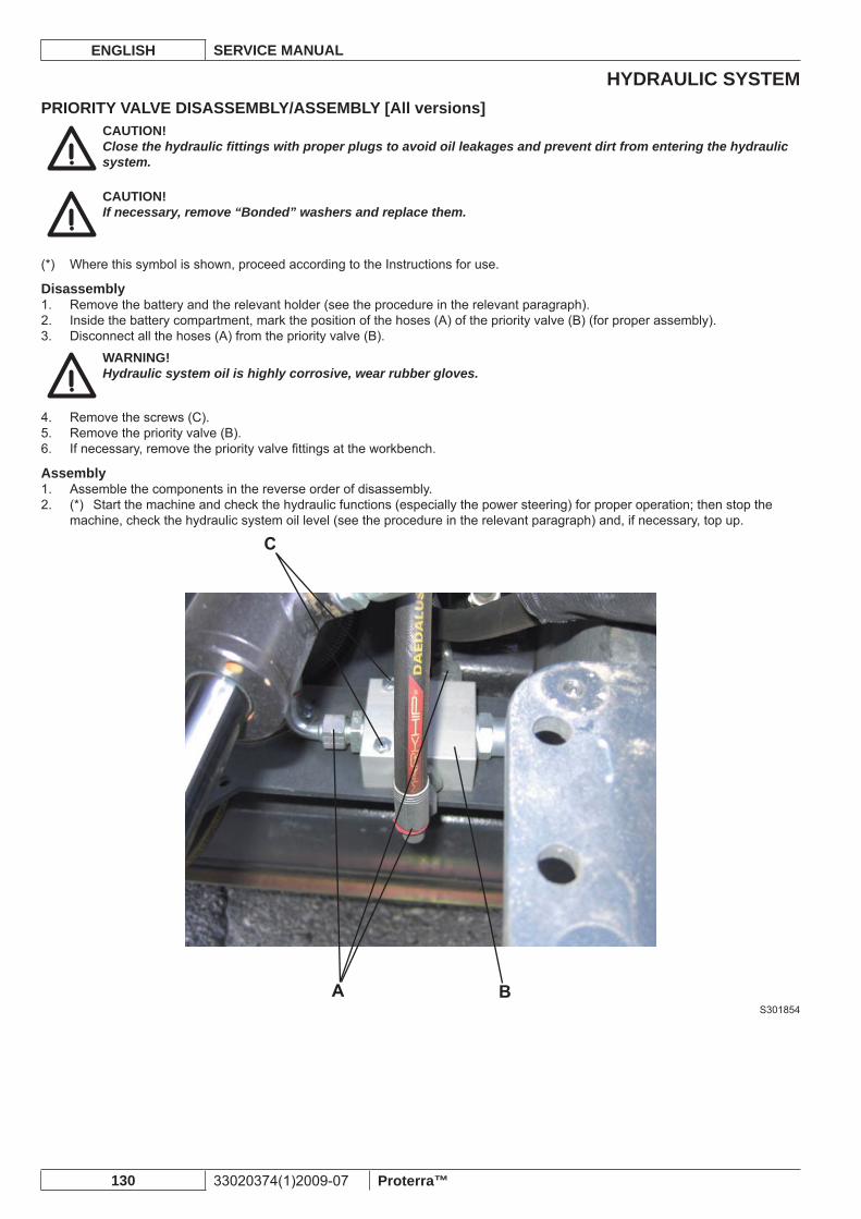
HYDRAULIC SYSTEMENGLISH SERVICE MANUAL
130 33020374(1)2009-07 Proterra™
PRIORITY VALVE DISASSEMBLY/ASSEMBLY [All versions]CAUTION!Close the hydraulic fi ttings with proper plugs to avoid oil leakages and prevent dirt from entering the hydraulic system.
CAUTION!If necessary, remove “Bonded” washers and replace them.
Where this symbol is shown, proceed according to the Instructions for use.(*)
DisassemblyRemove the battery and the relevant holder (see the procedure in the relevant paragraph).1. Inside the battery compartment, mark the position of the hoses (A) of the priority valve (B) (for proper assembly).2. Disconnect all the hoses (A) from the priority valve (B).3.
WARNING!Hydraulic system oil is highly corrosive, wear rubber gloves.
Remove the screws (C).4. Remove the priority valve (B).5. If necessary, remove the priority valve fi ttings at the workbench.6.
AssemblyAssemble the components in the reverse order of disassembly.1. (*) Start the machine and check the hydraulic functions (especially the power steering) for proper operation; then stop the 2. machine, check the hydraulic system oil level (see the procedure in the relevant paragraph) and, if necessary, top up.
S301854
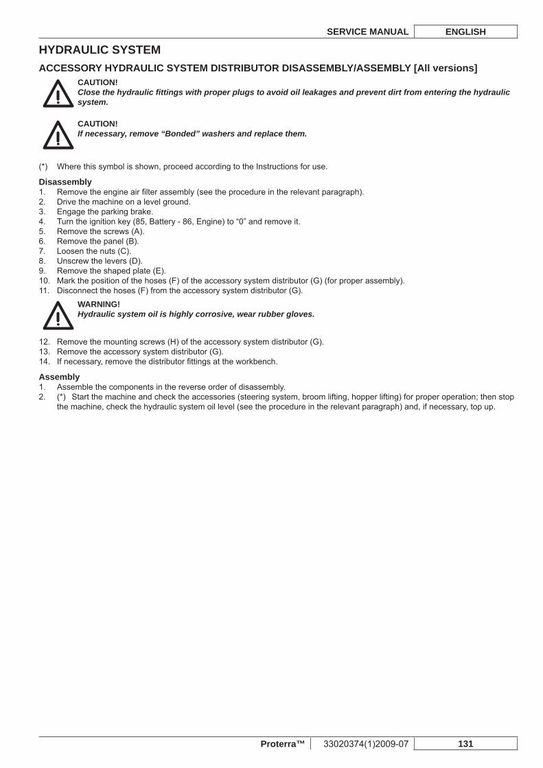
HYDRAULIC SYSTEMSERVICE MANUAL ENGLISH
Proterra™ 33020374(1)2009-07 131
ACCESSORY HYDRAULIC SYSTEM DISTRIBUTOR DISASSEMBLY/ASSEMBLY [All versions]CAUTION!Close the hydraulic fi ttings with proper plugs to avoid oil leakages and prevent dirt from entering the hydraulic system.
CAUTION!If necessary, remove “Bonded” washers and replace them.
Where this symbol is shown, proceed according to the Instructions for use.(*)
DisassemblyRemove the engine air fi lter assembly (see the procedure in the relevant paragraph).1. Drive the machine on a level ground.2. Engage the parking brake.3. Turn the ignition key (85, Battery - 86, Engine) to “0” and remove it.4. Remove the screws (A).5. Remove the panel (B).6. Loosen the nuts (C).7. Unscrew the levers (D).8. Remove the shaped plate (E).9. Mark the position of the hoses (F) of the accessory system distributor (G) (for proper assembly).10. Disconnect the hoses (F) from the accessory system distributor (G).11.
WARNING!Hydraulic system oil is highly corrosive, wear rubber gloves.
Remove the mounting screws (H) of the accessory system distributor (G).12. Remove the accessory system distributor (G).13. If necessary, remove the distributor fi ttings at the workbench.14.
AssemblyAssemble the components in the reverse order of disassembly.1. (*) Start the machine and check the accessories (steering system, broom lifting, hopper lifting) for proper operation; then stop 2. the machine, check the hydraulic system oil level (see the procedure in the relevant paragraph) and, if necessary, top up.
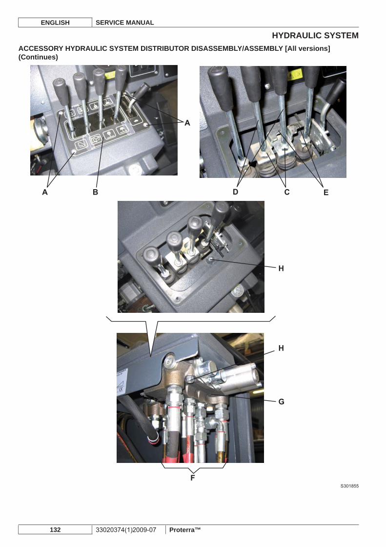
HYDRAULIC SYSTEMENGLISH SERVICE MANUAL
132 33020374(1)2009-07 Proterra™
ACCESSORY HYDRAULIC SYSTEM DISTRIBUTOR DISASSEMBLY/ASSEMBLY [All versions] (Continues)
S301855
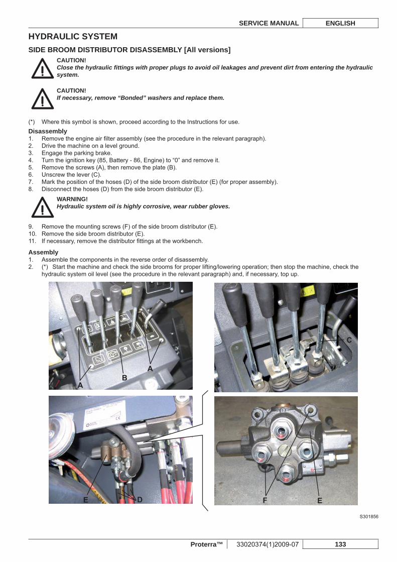
HYDRAULIC SYSTEMSERVICE MANUAL ENGLISH
Proterra™ 33020374(1)2009-07 133
SIDE BROOM DISTRIBUTOR DISASSEMBLY [All versions]CAUTION!Close the hydraulic fi ttings with proper plugs to avoid oil leakages and prevent dirt from entering the hydraulic system.
CAUTION!If necessary, remove “Bonded” washers and replace them.
Where this symbol is shown, proceed according to the Instructions for use.(*) Disassembly
Remove the engine air fi lter assembly (see the procedure in the relevant paragraph).1. Drive the machine on a level ground.2. Engage the parking brake.3. Turn the ignition key (85, Battery - 86, Engine) to “0” and remove it.4. Remove the screws (A), then remove the plate (B).5. Unscrew the lever (C).6. Mark the position of the hoses (D) of the side broom distributor (E) (for proper assembly).7. Disconnect the hoses (D) from the side broom distributor (E).8.
WARNING!Hydraulic system oil is highly corrosive, wear rubber gloves.
Remove the mounting screws (F) of the side broom distributor (E).9. Remove the side broom distributor (E).10. If necessary, remove the distributor fi ttings at the workbench.11.
AssemblyAssemble the components in the reverse order of disassembly.1. (*) Start the machine and check the side brooms for proper lifting/lowering operation; then stop the machine, check the 2. hydraulic system oil level (see the procedure in the relevant paragraph) and, if necessary, top up.
S301856
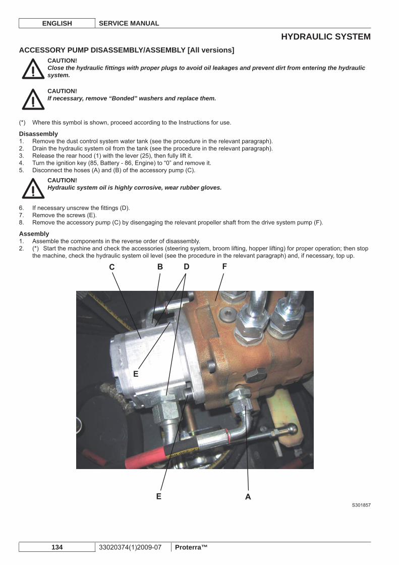
HYDRAULIC SYSTEMENGLISH SERVICE MANUAL
134 33020374(1)2009-07 Proterra™
ACCESSORY PUMP DISASSEMBLY/ASSEMBLY [All versions]CAUTION!Close the hydraulic fi ttings with proper plugs to avoid oil leakages and prevent dirt from entering the hydraulic system.
CAUTION!If necessary, remove “Bonded” washers and replace them.
Where this symbol is shown, proceed according to the Instructions for use.(*)
DisassemblyRemove the dust control system water tank (see the procedure in the relevant paragraph).1. Drain the hydraulic system oil from the tank (see the procedure in the relevant paragraph).2. Release the rear hood (1) with the lever (25), then fully lift it.3. Turn the ignition key (85, Battery - 86, Engine) to “0” and remove it.4. Disconnect the hoses (A) and (B) of the accessory pump (C).5.
CAUTION!Hydraulic system oil is highly corrosive, wear rubber gloves.
If necessary unscrew the fi ttings (D).6. Remove the screws (E).7. Remove the accessory pump (C) by disengaging the relevant propeller shaft from the drive system pump (F).8.
AssemblyAssemble the components in the reverse order of disassembly.1. (*) Start the machine and check the accessories (steering system, broom lifting, hopper lifting) for proper operation; then stop 2. the machine, check the hydraulic system oil level (see the procedure in the relevant paragraph) and, if necessary, top up.
S301857
HYDRAULIC SYSTEMSERVICE MANUAL ENGLISH
Proterra™ 33020374(1)2009-07 135
DRIVE SYSTEM PUMP DISASSEMBLY/ASSEMBLY [All versions]CAUTION!Close the hydraulic fi ttings with proper plugs to avoid oil leakages and prevent dirt from entering the hydraulic system.
CAUTION!If necessary, remove “Bonded” washers and replace them.
Where this symbol is shown, proceed according to the Instructions for use.(*)
DisassemblyRemove the dust control system water tank (see the procedure in the relevant paragraph).1. Drain the hydraulic system oil from the tank (see the procedure in the relevant paragraph).2. Release the rear hood (1) with the lever (25), then fully lift it.3. Turn the ignition key (85, Battery - 86, Engine) to “0” and remove it.4. Disconnect the hoses (A) and (B) of the accessory pump (C).5.
WARNING!Hydraulic system oil is highly corrosive, wear rubber gloves.
Mark the position of the hoses (D), (E), (F) and (G) of the drive system pump (H) (for proper assembly).6. Disconnect the hoses (D), (E), (F) and (G) of the drive system pump (H).7. If necessary unscrew the fi ttings (I).8. Remove the fastener (J), then release the ball end (K) of the tie rod (L) from the control lever (M) of the drive system pump (H).9. Remove the screws (N).10. Remove the drive system pump (H) by disengaging it from the engine transmission joint (the weight of the drive system pump 11. with accessory pump: 44 lb (20 kg)).At the workbench, if necessary, remove the screws (O) and separate the accessory pump (C) from the drive system pump (H) 12. by disengaging the propeller shaft which connects the pumps.
AssemblyAssemble the components in the reverse order of disassembly.1. (*) Start the machine and check the hydraulic functions for proper operation; then stop the machine, check the hydraulic 2. system oil level (see the procedure in the relevant paragraph) and, if necessary, top up.Adjust the forward/reverse gear pedal neutral position (see the procedure in the relevant paragraph).3.
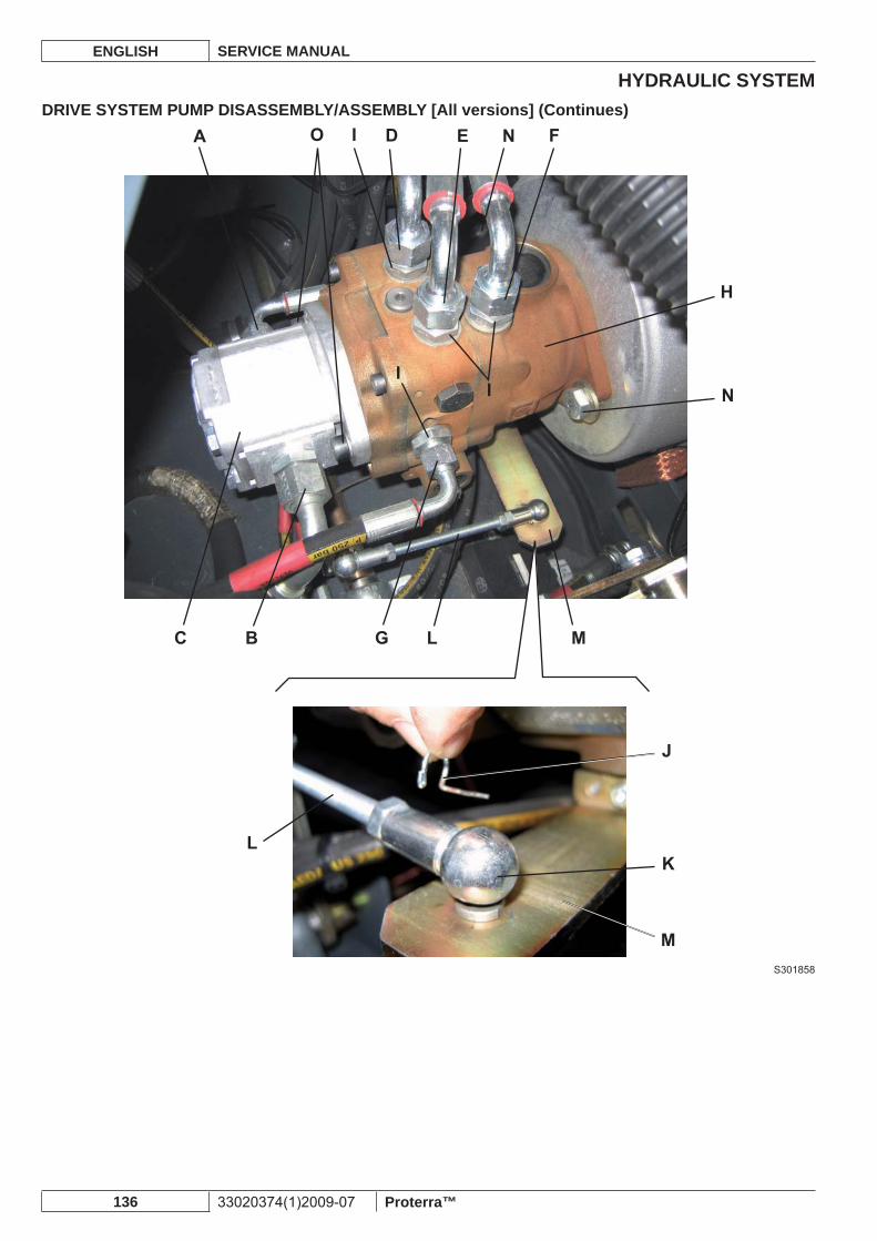
HYDRAULIC SYSTEMENGLISH SERVICE MANUAL
136 33020374(1)2009-07 Proterra™
DRIVE SYSTEM PUMP DISASSEMBLY/ASSEMBLY [All versions] (Continues)
S301858
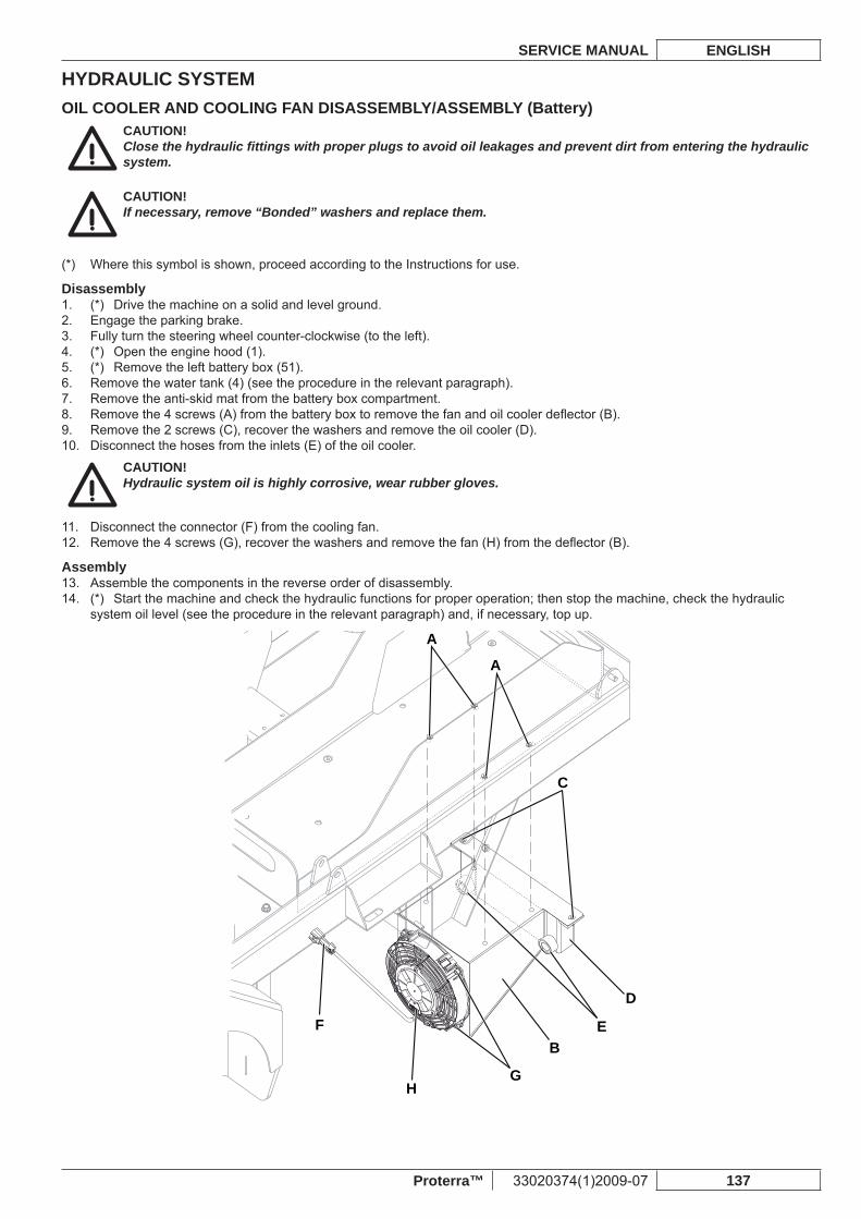
HYDRAULIC SYSTEMSERVICE MANUAL ENGLISH
Proterra™ 33020374(1)2009-07 137
OIL COOLER AND COOLING FAN DISASSEMBLY/ASSEMBLY (Battery)CAUTION!Close the hydraulic fi ttings with proper plugs to avoid oil leakages and prevent dirt from entering the hydraulic system.
CAUTION!If necessary, remove “Bonded” washers and replace them.
Where this symbol is shown, proceed according to the Instructions for use.(*)
Disassembly(*) Drive the machine on a solid and level ground.1. Engage the parking brake.2. Fully turn the steering wheel counter-clockwise (to the left).3. (*) Open the engine hood (1).4. (*) Remove the left battery box (51).5. Remove the water tank (4) (see the procedure in the relevant paragraph).6. Remove the anti-skid mat from the battery box compartment.7. Remove the 4 screws (A) from the battery box to remove the fan and oil cooler defl ector (B).8. Remove the 2 screws (C), recover the washers and remove the oil cooler (D).9. Disconnect the hoses from the inlets (E) of the oil cooler.10.
CAUTION!Hydraulic system oil is highly corrosive, wear rubber gloves.
Disconnect the connector (F) from the cooling fan.11. Remove the 4 screws (G), recover the washers and remove the fan (H) from the defl ector (B).12.
AssemblyAssemble the components in the reverse order of disassembly.13. (*) Start the machine and check the hydraulic functions for proper operation; then stop the machine, check the hydraulic 14. system oil level (see the procedure in the relevant paragraph) and, if necessary, top up.
A
A
C
BF
HG
E
D
HYDRAULIC SYSTEMENGLISH SERVICE MANUAL
138 33020374(1)2009-07 Proterra™
ELECTRICAL SYSTEMSERVICE MANUAL ENGLISH
Proterra™ 33020374(1)2009-07 139
ELECTRICAL SYSTEMTROUBLESHOOTING [All versions]See the previous chapters relevant to the use of the electrical system.Other possible causes:
The batteries are discharged or the connections are not effi cient (charge the batteries or clean the connections).1. The fuses are blown (replace).2. The wiring harness is cut or pinched (repair).3.
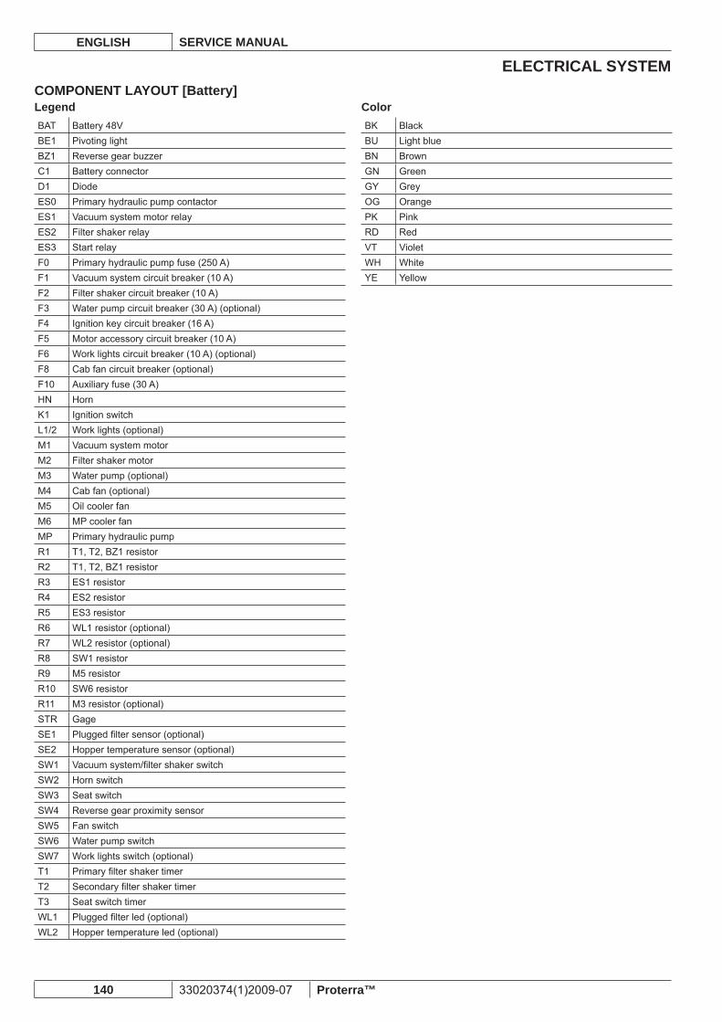
ELECTRICAL SYSTEMENGLISH SERVICE MANUAL
140 33020374(1)2009-07 Proterra™
COMPONENT LAYOUT [Battery]LegendBAT Battery 48VBE1 Pivoting lightBZ1 Reverse gear buzzerC1 Battery connectorD1 DiodeES0 Primary hydraulic pump contactorES1 Vacuum system motor relayES2 Filter shaker relayES3 Start relayF0 Primary hydraulic pump fuse (250 A)F1 Vacuum system circuit breaker (10 A)F2 Filter shaker circuit breaker (10 A)F3 Water pump circuit breaker (30 A) (optional)F4 Ignition key circuit breaker (16 A)F5 Motor accessory circuit breaker (10 A)F6 Work lights circuit breaker (10 A) (optional)F8 Cab fan circuit breaker (optional)F10 Auxiliary fuse (30 A)HN HornK1 Ignition switchL1/2 Work lights (optional)M1 Vacuum system motorM2 Filter shaker motorM3 Water pump (optional)M4 Cab fan (optional)M5 Oil cooler fanM6 MP cooler fanMP Primary hydraulic pumpR1 T1, T2, BZ1 resistorR2 T1, T2, BZ1 resistorR3 ES1 resistorR4 ES2 resistorR5 ES3 resistorR6 WL1 resistor (optional)R7 WL2 resistor (optional)R8 SW1 resistorR9 M5 resistorR10 SW6 resistorR11 M3 resistor (optional)STR GageSE1 Plugged fi lter sensor (optional)SE2 Hopper temperature sensor (optional)SW1 Vacuum system/fi lter shaker switchSW2 Horn switchSW3 Seat switch SW4 Reverse gear proximity sensorSW5 Fan switch SW6 Water pump switch SW7 Work lights switch (optional)T1 Primary fi lter shaker timerT2 Secondary fi lter shaker timerT3 Seat switch timerWL1 Plugged fi lter led (optional)WL2 Hopper temperature led (optional)
ColorBK BlackBU Light blueBN BrownGN GreenGY GreyOG OrangePK PinkRD RedVT VioletWH WhiteYE Yellow
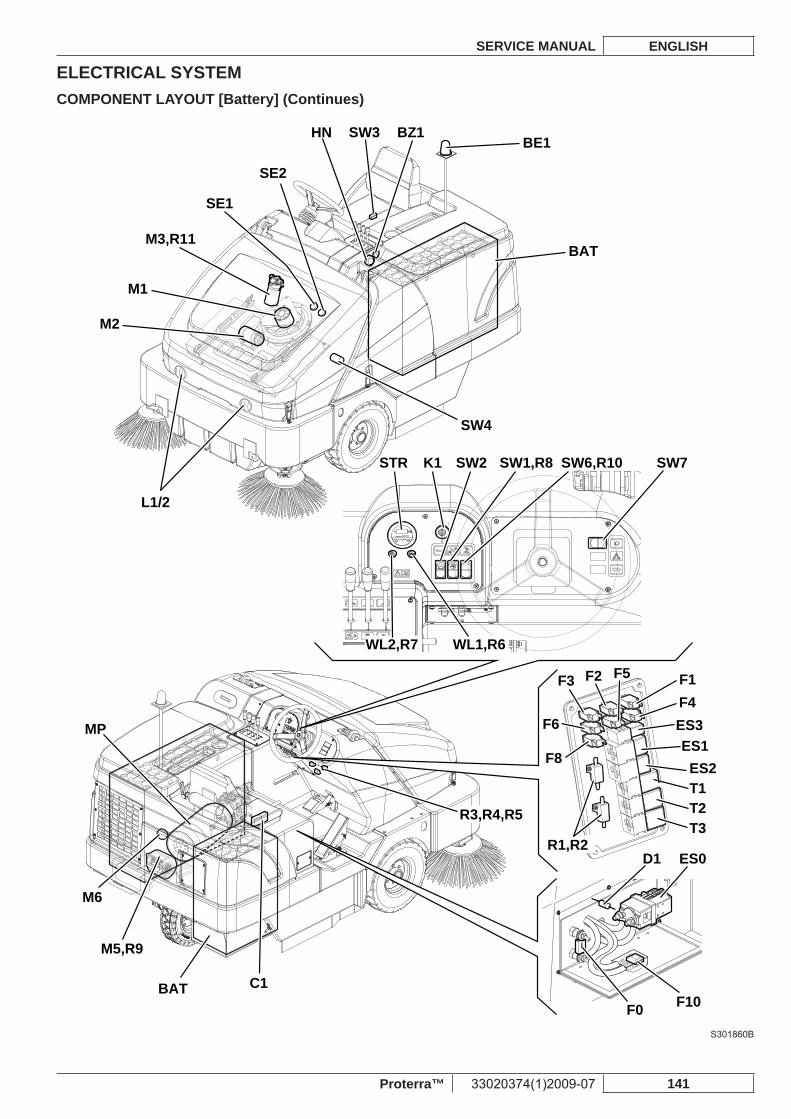
ELECTRICAL SYSTEMSERVICE MANUAL ENGLISH
Proterra™ 33020374(1)2009-07 141
COMPONENT LAYOUT [Battery] (Continues)
BE1
BAT C1
F0
F1F2F3F4
ES1ES3
ES2T1T2T3
F5
F6
F8
F10
D1 ES0
BAT
BZ1HN SW3
L1/2
K1
M1
M2
M5,R9
M6
MP
M3,R11
SW4
STR
WL1,R6WL2,R7
SW2 SW1,R8 SW6,R10 SW7
SE1
SE2
R1,R2
R3,R4,R5
S301860B
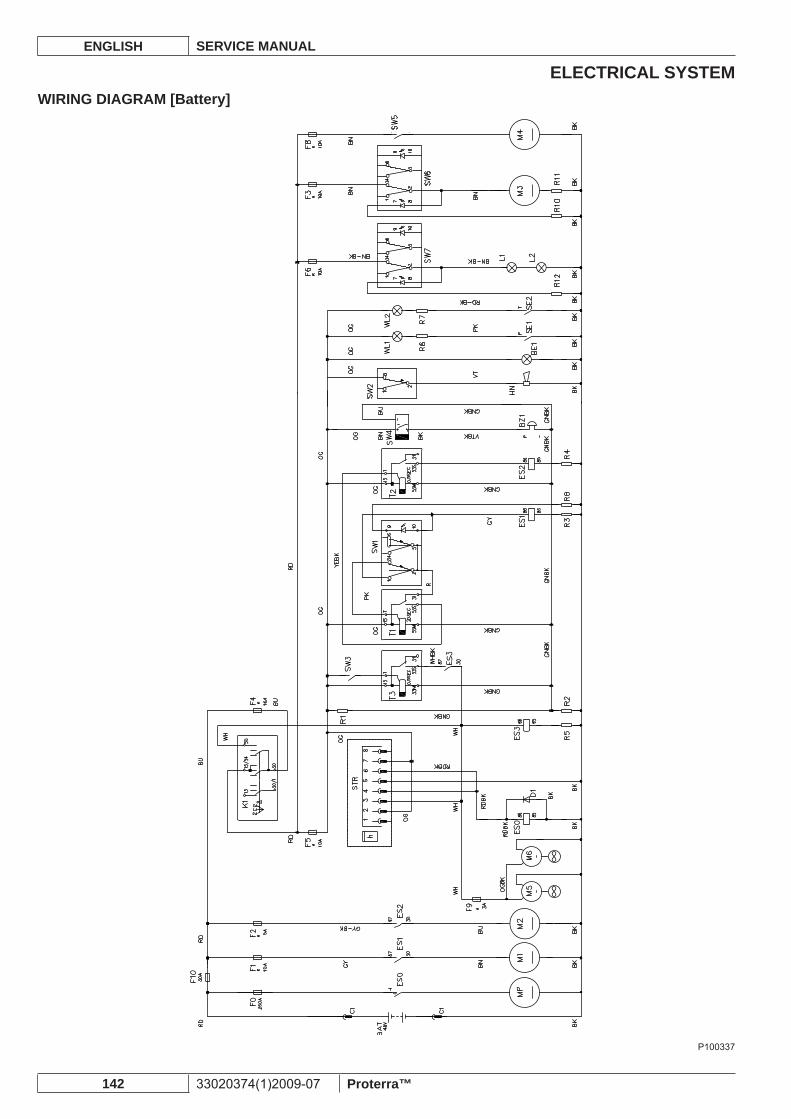
ELECTRICAL SYSTEMENGLISH SERVICE MANUAL
142 33020374(1)2009-07 Proterra™
WIRING DIAGRAM [Battery]
P100337
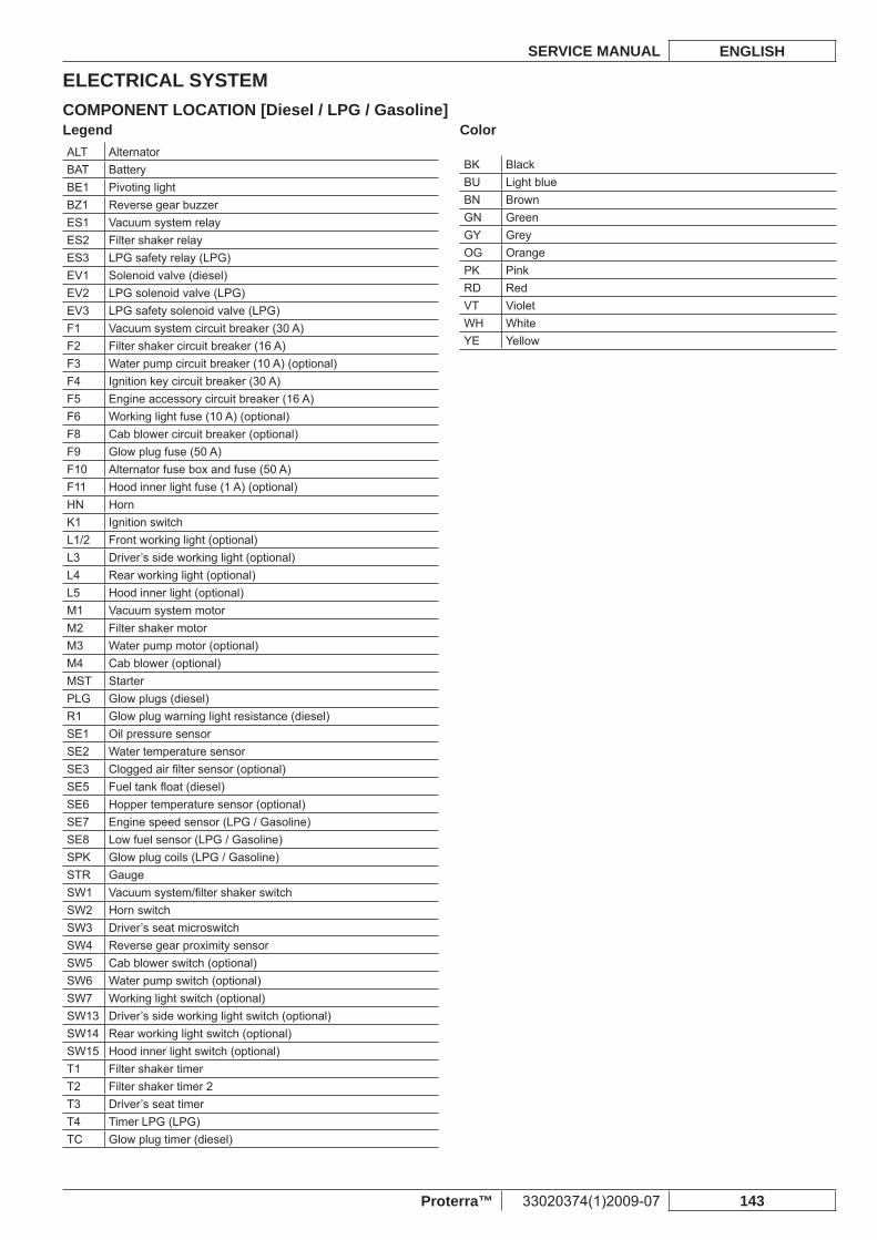
ELECTRICAL SYSTEMSERVICE MANUAL ENGLISH
Proterra™ 33020374(1)2009-07 143
COMPONENT LOCATION [Diesel / LPG / Gasoline]LegendALT AlternatorBAT BatteryBE1 Pivoting lightBZ1 Reverse gear buzzerES1 Vacuum system relayES2 Filter shaker relayES3 LPG safety relay (LPG)EV1 Solenoid valve (diesel)EV2 LPG solenoid valve (LPG)EV3 LPG safety solenoid valve (LPG)F1 Vacuum system circuit breaker (30 A)F2 Filter shaker circuit breaker (16 A)F3 Water pump circuit breaker (10 A) (optional)F4 Ignition key circuit breaker (30 A)F5 Engine accessory circuit breaker (16 A)F6 Working light fuse (10 A) (optional)F8 Cab blower circuit breaker (optional)F9 Glow plug fuse (50 A)F10 Alternator fuse box and fuse (50 A)F11 Hood inner light fuse (1 A) (optional)HN HornK1 Ignition switchL1/2 Front working light (optional)L3 Driver’s side working light (optional)L4 Rear working light (optional)L5 Hood inner light (optional)M1 Vacuum system motorM2 Filter shaker motorM3 Water pump motor (optional)M4 Cab blower (optional)MST StarterPLG Glow plugs (diesel)R1 Glow plug warning light resistance (diesel)SE1 Oil pressure sensorSE2 Water temperature sensorSE3 Clogged air fi lter sensor (optional)SE5 Fuel tank fl oat (diesel)SE6 Hopper temperature sensor (optional)SE7 Engine speed sensor (LPG / Gasoline)SE8 Low fuel sensor (LPG / Gasoline)SPK Glow plug coils (LPG / Gasoline)STR GaugeSW1 Vacuum system/fi lter shaker switchSW2 Horn switchSW3 Driver’s seat microswitchSW4 Reverse gear proximity sensorSW5 Cab blower switch (optional)SW6 Water pump switch (optional)SW7 Working light switch (optional)SW13 Driver’s side working light switch (optional)SW14 Rear working light switch (optional)SW15 Hood inner light switch (optional)T1 Filter shaker timerT2 Filter shaker timer 2T3 Driver’s seat timerT4 Timer LPG (LPG)TC Glow plug timer (diesel)
Color
BK BlackBU Light blueBN BrownGN GreenGY GreyOG OrangePK PinkRD RedVT VioletWH WhiteYE Yellow
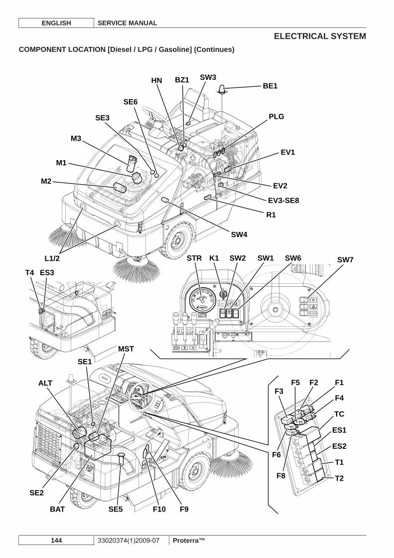
ELECTRICAL SYSTEMENGLISH SERVICE MANUAL
144 33020374(1)2009-07 Proterra™
COMPONENT LOCATION [Diesel / LPG / Gasoline] (Continues)
M1
M2
L1/2
ES3T4
BE1
PLG
EV1
M3
SE3
SE6
BZ1HN
EV2
EV3-SE8
STR
R1
SW4
K1 SW2 SW1 SW6 SW7
F1
F4
TC
ES1
ES2
T2
T1
F5 F2F3
F6
F8
A
SE1
LT
SE2
BAT SE5 F10 F9
MST
SW3
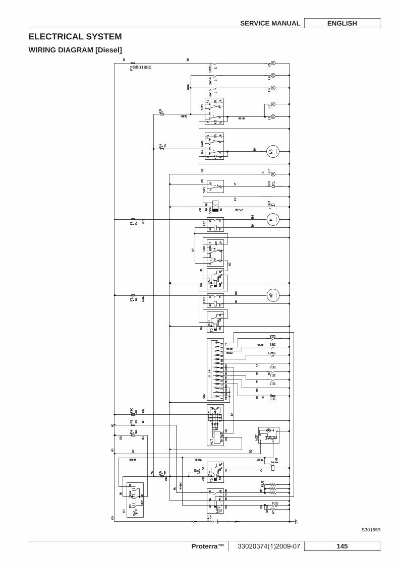
ELECTRICAL SYSTEMSERVICE MANUAL ENGLISH
Proterra™ 33020374(1)2009-07 145
S301860
WIRING DIAGRAM [Diesel]
S301859
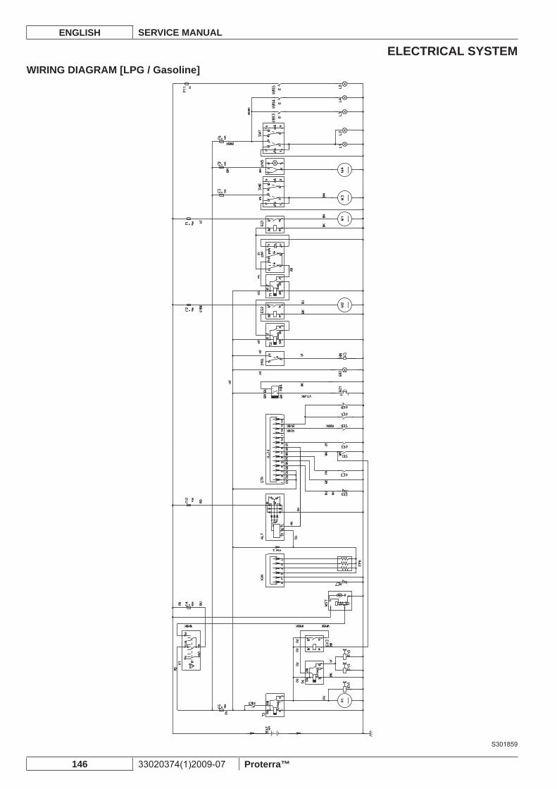
ELECTRICAL SYSTEMENGLISH SERVICE MANUAL
146 33020374(1)2009-07 Proterra™
WIRING DIAGRAM [LPG / Gasoline]
S301859
ELECTRICAL SYSTEMSERVICE MANUAL ENGLISH
Proterra™ 33020374(1)2009-07 147
BATTERY FLUID LEVEL CHECK [Battery]WARNING!Always protect body parts (eyes, hair, hands, etc.) when checking or cleaning the batteries.
Drive the machine on a level ground.1. Engage the parking brake.2. Turn the ignition key (85) to “0” and remove it.3. Disconnect the battery connector (57) with the quick release control (50).4. Release the rear hood (1) with the lever (25), then fully lift it.5. Open the plugs (A) and check the electrolyte level of batteries (B) and (C). For the proper level of the battery electrolyte refer 6. to the Battery Manual. If necessary add distilled water to restore the electrolyte level. The electrolyte level must be the same in all the elements so that the electrolyte density is even.Check the terminals (D) and (E) of the battery (B) for oxidation.Check the battery terminals (E), (F), (G) and (H) for oxidation.Clean and dry the battery surface.Connect the battery connector (57).7. Close the rear hood (1).8.
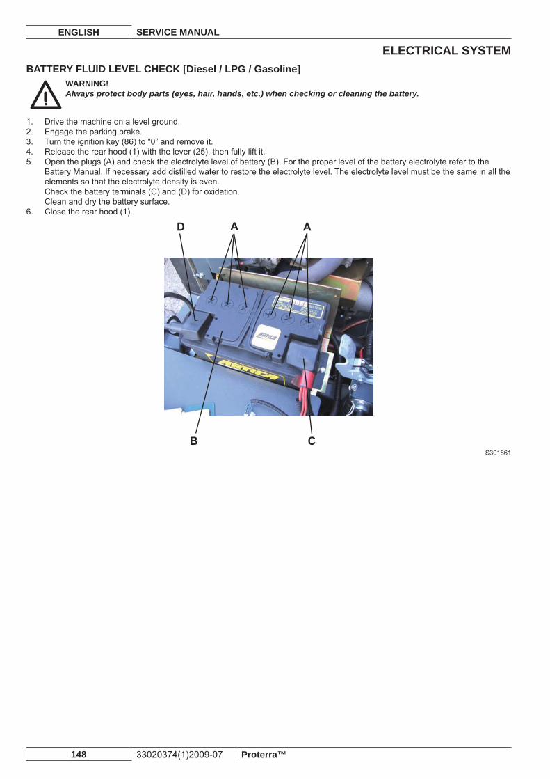
ELECTRICAL SYSTEMENGLISH SERVICE MANUAL
148 33020374(1)2009-07 Proterra™
BATTERY FLUID LEVEL CHECK [Diesel / LPG / Gasoline]WARNING!Always protect body parts (eyes, hair, hands, etc.) when checking or cleaning the battery.
Drive the machine on a level ground.1. Engage the parking brake.2. Turn the ignition key (86) to “0” and remove it.3. Release the rear hood (1) with the lever (25), then fully lift it.4. Open the plugs (A) and check the electrolyte level of battery (B). For the proper level of the battery electrolyte refer to the 5. Battery Manual. If necessary add distilled water to restore the electrolyte level. The electrolyte level must be the same in all the elements so that the electrolyte density is even.Check the battery terminals (C) and (D) for oxidation.Clean and dry the battery surface.Close the rear hood (1).6.
S301861
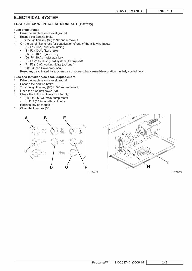
ELECTRICAL SYSTEMSERVICE MANUAL ENGLISH
Proterra™ 33020374(1)2009-07 149
FUSE CHECK/REPLACEMENT/RESET [Battery]Fuse check/reset
Drive the machine on a level ground.1. Engage the parking brake.2. Turn the ignition key (85) to “0” and remove it.3. On the panel (38), check for deactivation of one of the following fuses:4.
(A): F1 (10 A), dust vacuuming• (B): F2 (10 A), fi lter shaker• (C): F4 (16 A), ignition key• (D): F5 (10 A), motor auxiliary• (E): F3 (2 A), dust guard system (if equipped)• (F): F6 (10 A), working lights (optional)• (G): F8, cab blower (optional)•
Reset any deactivated fuse, when the component that caused deactivation has fully cooled down.
Fuse and lamellar fuse check/replacementDrive the machine on a level ground.1. Engage the parking brake.2. Turn the ignition key (85) to “0” and remove it.3. Open the fuse box cover (53).4. Check the following fuses for integrity:5.
(H): F0 (250 A), main pump motor• (I): F10 (30 A), auxiliary circuits•
Replace any open fuse.Close the fuse box (53).6.
A B E
G
C
D F HI
P100338 P100339S
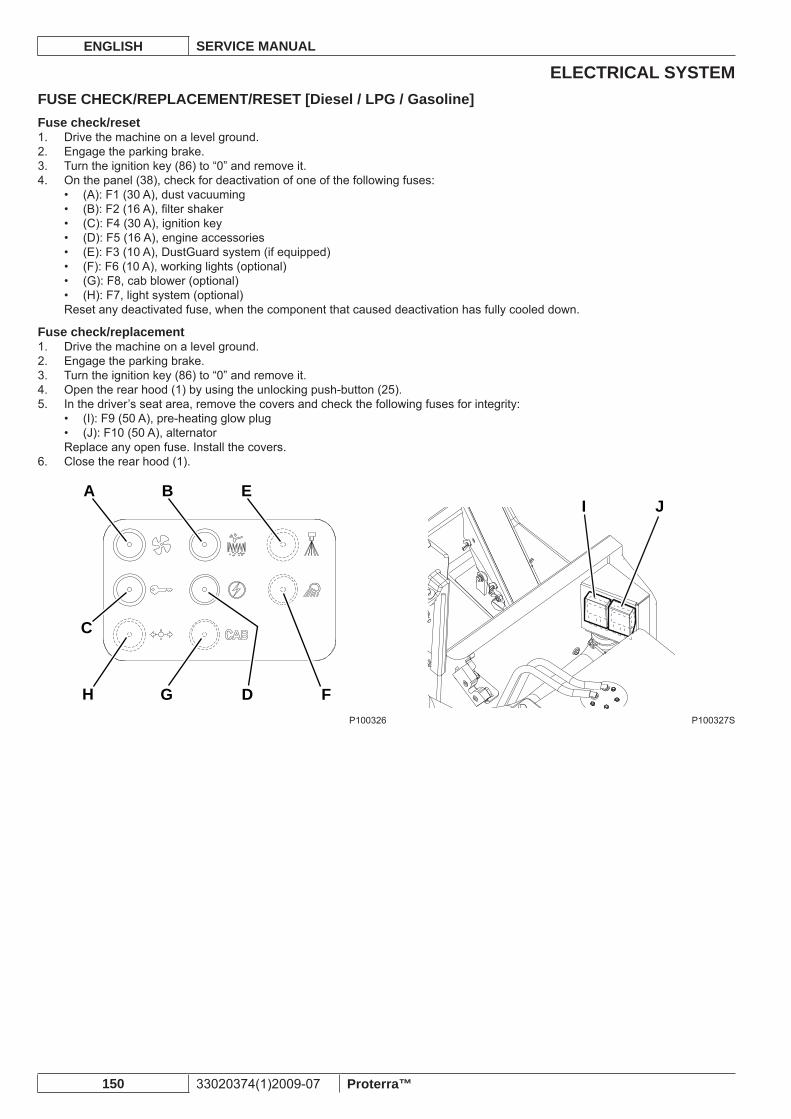
ELECTRICAL SYSTEMENGLISH SERVICE MANUAL
150 33020374(1)2009-07 Proterra™
FUSE CHECK/REPLACEMENT/RESET [Diesel / LPG / Gasoline]Fuse check/reset
Drive the machine on a level ground.1. Engage the parking brake.2. Turn the ignition key (86) to “0” and remove it.3. On the panel (38), check for deactivation of one of the following fuses:4.
(A): F1 (30 A), dust vacuuming• (B): F2 (16 A), fi lter shaker• (C): F4 (30 A), ignition key• (D): F5 (16 A), engine accessories• (E): F3 (10 A), DustGuard system (if equipped)• (F): F6 (10 A), working lights (optional)• (G): F8, cab blower (optional)• (H): F7, light system (optional)•
Reset any deactivated fuse, when the component that caused deactivation has fully cooled down.
Fuse check/replacementDrive the machine on a level ground.1. Engage the parking brake.2. Turn the ignition key (86) to “0” and remove it.3. Open the rear hood (1) by using the unlocking push-button (25).4. In the driver’s seat area, remove the covers and check the following fuses for integrity:5.
(I): F9 (50 A), pre-heating glow plug• (J): F10 (50 A), alternator•
Replace any open fuse. Install the covers.Close the rear hood (1).6.
A B E
G
C
D FH
I J
P100326 P100327S
ELECTRICAL SYSTEMSERVICE MANUAL ENGLISH
Proterra™ 33020374(1)2009-07 151
BATTERY DISASSEMBLY/ASSEMBLY [Battery]WARNING!Do not tilt the lead batteries (WET) to prevent the highly corrosive acid from leaking out of the batteries.Do not connect, not even accidentally, the battery positive and negative terminals by using tools, keys, etc. This could cause dangerous short-circuits.
For approved battery types, see the Technical Data paragraph.The batteries must be installed as shown in the diagram (59).
WARNING!WET batteries are inside an appropriate container to prevent the acid form leaking.Do not install WET batteries without an appropriate container.
DisassemblyDrive the machine on a level ground and engage the parking brake.1. Check that the ignition key (85) has been removed.2. Disconnect the battery connector (57) with the control (50).3. Open the battery compartment hood (1) by using the unlocking push-button (25).4. Disconnect the battery wiring harness (51 and 52).5. Check that WET battery caps (60) are closed, to prevent the highly corrosive acid from leaking out of the batteries.6. With the help of an assistant and an appropriate hoisting system, remove the batteries (51 and 52).7.
AssemblyWith the help of an assistant and an appropriate hoisting system, install the batteries and connect them as shown in the 8. diagram (59). Connect the battery connector (57) and close the hood (1).9. If necessary, charge the batteries (see the procedure in the Instructions for use).10.
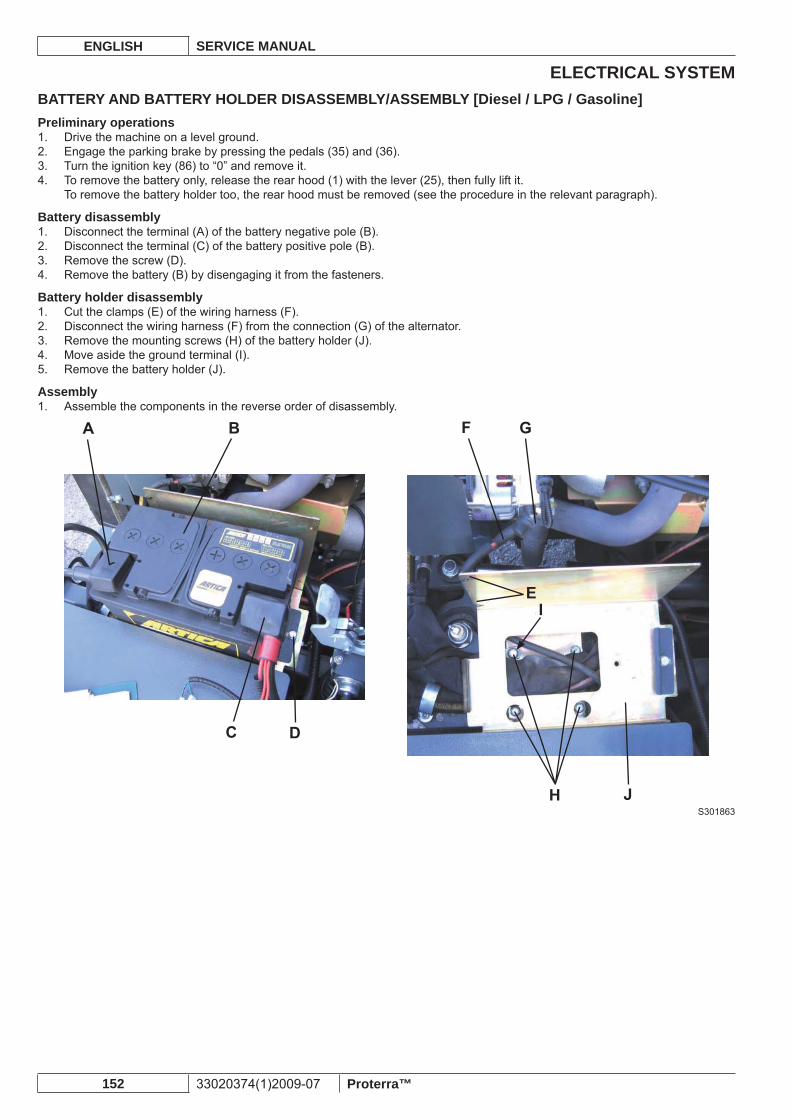
ELECTRICAL SYSTEMENGLISH SERVICE MANUAL
152 33020374(1)2009-07 Proterra™
BATTERY AND BATTERY HOLDER DISASSEMBLY/ASSEMBLY [Diesel / LPG / Gasoline]Preliminary operations
Drive the machine on a level ground.1. Engage the parking brake by pressing the pedals (35) and (36).2. Turn the ignition key (86) to “0” and remove it.3. To remove the battery only, release the rear hood (1) with the lever (25), then fully lift it.4. To remove the battery holder too, the rear hood must be removed (see the procedure in the relevant paragraph).
Battery disassemblyDisconnect the terminal (A) of the battery negative pole (B).1. Disconnect the terminal (C) of the battery positive pole (B).2. Remove the screw (D).3. Remove the battery (B) by disengaging it from the fasteners.4.
Battery holder disassemblyCut the clamps (E) of the wiring harness (F).1. Disconnect the wiring harness (F) from the connection (G) of the alternator.2. Remove the mounting screws (H) of the battery holder (J).3. Move aside the ground terminal (I).4. Remove the battery holder (J).5.
AssemblyAssemble the components in the reverse order of disassembly.1.
S301863
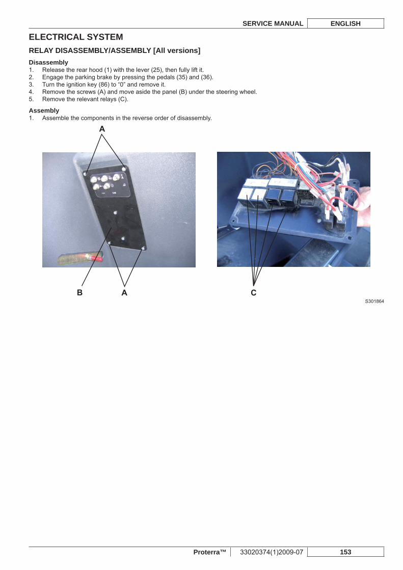
ELECTRICAL SYSTEMSERVICE MANUAL ENGLISH
Proterra™ 33020374(1)2009-07 153
RELAY DISASSEMBLY/ASSEMBLY [All versions]Disassembly
Release the rear hood (1) with the lever (25), then fully lift it.1. Engage the parking brake by pressing the pedals (35) and (36).2. Turn the ignition key (86) to “0” and remove it.3. Remove the screws (A) and move aside the panel (B) under the steering wheel.4. Remove the relevant relays (C).5.
AssemblyAssemble the components in the reverse order of disassembly.1.
S301864
ELECTRICAL SYSTEMENGLISH SERVICE MANUAL
154 33020374(1)2009-07 Proterra™


Nilfisk-Advance, Inc. 14600 21st Avenue North Plymouth, MN, 55447-3408 www.nilfisk-advance.com Phone: 800-989-2235 Fax: 800-989-6566©2008 Nilfisk-Advance, Inc., Plymouth, MN 55447-3408 Printed in Italy