Embed Size (px)
Citation preview

PARAMETRIC STRUCTURAL MODELING
User Manual
for Version 1.2.2
written by Clemens Preisinger
October 3, 2016

Contents
1. Introduction 7
1.1. Citing Karamba . . . . . . . . . . . . . . . . . . . . . . . . . . 7
1.2. How to obtain a pro- or pro-student-license . . . . . . . . . . 7
2. What's new in version 1.2.1. 9
2.1. Disclaimer . . . . . . . . . . . . . . . . . . . . . . . . . . . . . 10
3. Installation 11
4. Quick start 13
4.1. Basic Example . . . . . . . . . . . . . . . . . . . . . . . . . . . 13
4.2. Physical Units . . . . . . . . . . . . . . . . . . . . . . . . . . . 14
4.3. Elements . . . . . . . . . . . . . . . . . . . . . . . . . . . . . . 15
4.4. Materials . . . . . . . . . . . . . . . . . . . . . . . . . . . . . . 15
4.5. Cross Sections . . . . . . . . . . . . . . . . . . . . . . . . . . . 16
4.6. Supports . . . . . . . . . . . . . . . . . . . . . . . . . . . . . . 16
4.7. Loads . . . . . . . . . . . . . . . . . . . . . . . . . . . . . . . . 17
4.8. Model . . . . . . . . . . . . . . . . . . . . . . . . . . . . . . . . 17
4.9. Algorithms . . . . . . . . . . . . . . . . . . . . . . . . . . . . . 18
4.10. Visualization . . . . . . . . . . . . . . . . . . . . . . . . . . . . 18
4.11. Results . . . . . . . . . . . . . . . . . . . . . . . . . . . . . . . 19
5. Quick Component Reference 20
5.1. License . . . . . . . . . . . . . . . . . . . . . . . . . . . . . . . 20
5.2. Algorithms . . . . . . . . . . . . . . . . . . . . . . . . . . . . . 20
5.3. Cross Section . . . . . . . . . . . . . . . . . . . . . . . . . . . 20
5.4. Model . . . . . . . . . . . . . . . . . . . . . . . . . . . . . . . . 22
5.5. Export . . . . . . . . . . . . . . . . . . . . . . . . . . . . . . . 23
5.6. Load . . . . . . . . . . . . . . . . . . . . . . . . . . . . . . . . 23
5.7. Material . . . . . . . . . . . . . . . . . . . . . . . . . . . . . . 24
5.8. Results . . . . . . . . . . . . . . . . . . . . . . . . . . . . . . . 24
5.9. Utilities . . . . . . . . . . . . . . . . . . . . . . . . . . . . . . . 26
6. Component Reference 28
2

6.1. Ensemble . . . . . . . . . . . . . . . . . . . . . . . . . . . . . . 28
6.1.1. Activate Element . . . . . . . . . . . . . . . . . . . . 28
6.1.2. Assemble Model . . . . . . . . . . . . . . . . . . . . . 28
6.1.3. Connected Parts . . . . . . . . . . . . . . . . . . . . . 29
6.1.4. Disassemble Model . . . . . . . . . . . . . . . . . . . 30
6.1.5. Line to Beam . . . . . . . . . . . . . . . . . . . . . . 31
6.1.6. Index to Beam . . . . . . . . . . . . . . . . . . . . . . 32
6.1.7. Connectivity to Beam . . . . . . . . . . . . . . . . . . 33
6.1.8. Mesh to Shell . . . . . . . . . . . . . . . . . . . . . . 33
6.1.9. Modify Element . . . . . . . . . . . . . . . . . . . . . 34
6.1.10. Modify Element for Beams . . . . . . . . . . . . . . . 34
6.1.11. Modify Element for Shells . . . . . . . . . . . . . . . 38
6.1.12. Point-Mass . . . . . . . . . . . . . . . . . . . . . . . . 38
6.1.13. Disassemble Beam . . . . . . . . . . . . . . . . . . . . 39
6.1.14. Make Beam-Set . . . . . . . . . . . . . . . . . . . . . 39
6.1.15. Orientate Beam . . . . . . . . . . . . . . . . . . . . . 40
6.1.16. Select Beam . . . . . . . . . . . . . . . . . . . . . . . 41
6.1.17. Support . . . . . . . . . . . . . . . . . . . . . . . . . 42
6.2. Cross Section . . . . . . . . . . . . . . . . . . . . . . . . . . . 45
6.2.1. Beam Cross Section . . . . . . . . . . . . . . . . . . 46
6.2.2. Shell Cross Section . . . . . . . . . . . . . . . . . . . 47
6.2.3. Spring Cross Section . . . . . . . . . . . . . . . . . . 48
6.2.4. Beam-Joints . . . . . . . . . . . . . . . . . . . . . . . 49
6.2.5. Beam-Joint Agent . . . . . . . . . . . . . . . . . . . . 50
6.2.6. Disassemble Cross Section . . . . . . . . . . . . . . . 51
6.2.7. Eccentricity on Beam, Eccentricity on Cross Section 51
6.2.8. Cross Section Matcher . . . . . . . . . . . . . . . . . 53
6.2.9. Cross Section Range Selector . . . . . . . . . . . . . 54
6.2.10. Cross Section Selector . . . . . . . . . . . . . . . . . 54
6.2.11. Generate Cross Section Table . . . . . . . . . . . . . 55
6.2.12. Read Cross Section Table from File . . . . . . . . . . 56
6.3. Material . . . . . . . . . . . . . . . . . . . . . . . . . . . . . . 57
6.3.1. Material Properties . . . . . . . . . . . . . . . . . . . 57
6.3.2. Material Selection . . . . . . . . . . . . . . . . . . . . 59
6.3.3. Read Material Table from File . . . . . . . . . . . . 59
3
6.4. Load . . . . . . . . . . . . . . . . . . . . . . . . . . . . . . . . 60
6.4.1. Gravity . . . . . . . . . . . . . . . . . . . . . . . . . . 61
6.4.2. Point-Load . . . . . . . . . . . . . . . . . . . . . . . . 62
6.4.3. Imperfection-Load . . . . . . . . . . . . . . . . . . . . 62
6.4.4. Initial Strain-Load . . . . . . . . . . . . . . . . . . . . 63
6.4.5. Temperature-Load . . . . . . . . . . . . . . . . . . . 64
6.4.6. Line-Load on Element . . . . . . . . . . . . . . . . . 64
6.4.7. Mesh-Load . . . . . . . . . . . . . . . . . . . . . . . . 64
6.4.8. Prescribed displacements . . . . . . . . . . . . . . . . 68
6.5. Algorithms . . . . . . . . . . . . . . . . . . . . . . . . . . . . 69
6.5.1. Analyze Th. I . . . . . . . . . . . . . . . . . . . . . . 69
6.5.2. Analyze Th. II . . . . . . . . . . . . . . . . . . . . . . 71
6.5.3. Analyze Large Deformation . . . . . . . . . . . . . . 73
6.5.4. Buckling Modes . . . . . . . . . . . . . . . . . . . . . 75
6.5.5. Eigen Modes . . . . . . . . . . . . . . . . . . . . . . . 77
6.5.6. Natural Vibrations . . . . . . . . . . . . . . . . . . . 78
6.5.7. BESO for Beams . . . . . . . . . . . . . . . . . . . . 79
6.5.8. BESO for Shells . . . . . . . . . . . . . . . . . . . . . 84
6.5.9. Tension/Compression Eliminator . . . . . . . . . . . 86
6.5.10. Optimize Cross Section . . . . . . . . . . . . . . . . 87
6.6. Results . . . . . . . . . . . . . . . . . . . . . . . . . . . . . . 93
6.6.1. Deformation-Energy . . . . . . . . . . . . . . . . . . 93
6.6.2. ModelView . . . . . . . . . . . . . . . . . . . . . . . . 94
6.6.3. Nodal Displacements . . . . . . . . . . . . . . . . . . 99
6.6.4. Principal Strains Approximation . . . . . . . . . . . . 100
6.6.5. Reaction Forces . . . . . . . . . . . . . . . . . . . . . 101
6.6.6. Utilization of Elements . . . . . . . . . . . . . . . . . 101
6.6.7. Beam Displacements . . . . . . . . . . . . . . . . . . 103
6.6.8. BeamView . . . . . . . . . . . . . . . . . . . . . . . . 105
6.6.9. Resultant Section Forces . . . . . . . . . . . . . . . . 107
6.6.10. Beam Forces . . . . . . . . . . . . . . . . . . . . . . 109
6.6.11. Line Results on Shells . . . . . . . . . . . . . . . . . 110
6.6.12. Principal Force Directions on Shells . . . . . . . . . 115
6.6.13. Principal Stress Directions on Shells . . . . . . . . . 115
6.6.14. Shell Forces . . . . . . . . . . . . . . . . . . . . . . . 116
4

6.6.15. ShellView . . . . . . . . . . . . . . . . . . . . . . . . 116
6.7. Export . . . . . . . . . . . . . . . . . . . . . . . . . . . . . . . 118
6.7.1. Export Model to DStV . . . . . . . . . . . . . . . . . 118
6.8. Utilities . . . . . . . . . . . . . . . . . . . . . . . . . . . . . . . 118
6.8.1. Mesh Breps . . . . . . . . . . . . . . . . . . . . . . . . 118
6.8.2. Nearest Neighbors . . . . . . . . . . . . . . . . . . . . 120
6.8.3. Multi-dimensional Nearest Neighbors . . . . . . . . . 121
6.8.4. Remove Duplicate Lines . . . . . . . . . . . . . . . . 122
6.8.5. Remove Duplicate Points . . . . . . . . . . . . . . . . 122
6.8.6. Get Cells from Lines . . . . . . . . . . . . . . . . . . . 122
6.8.7. Line-Line Intersection . . . . . . . . . . . . . . . . . . 122
6.8.8. Element Felting . . . . . . . . . . . . . . . . . . . . . 123
6.8.9. Mapper . . . . . . . . . . . . . . . . . . . . . . . . . . 124
6.8.10. Interpolate Shape . . . . . . . . . . . . . . . . . . . . 125
6.8.11. Proximity Stitch . . . . . . . . . . . . . . . . . . . . . 126
6.8.12. Simple Stitch . . . . . . . . . . . . . . . . . . . . . . 127
6.8.13. Stacked Stitch . . . . . . . . . . . . . . . . . . . . . . 128
6.8.14. User Iso-Lines and Stream-Lines . . . . . . . . . . . 128
7. Trouble shooting 129
7.1. Karamba does not work for unknown reason . . . . . . . . . 130
7.2. �fem.karambaPINVOKE�-exception . . . . . . . . . . . . . . 131
7.3. The StackedStitch-components renders structures with over-
lapping diagonals . . . . . . . . . . . . . . . . . . . . . . . . . 132
7.4. Karamba does not work after reinstalling Grasshoper . . . . 132
7.5. Karamba does not appear nor any of its components seem
to be installed . . . . . . . . . . . . . . . . . . . . . . . . . . . 132
7.6. Karamba seems to get stuck while calculating a model . . . 133
7.7. Prede�ned displacements take no e�ect . . . . . . . . . . . . 133
7.8. The ModelView-component consistently displays all load cases
simultaneously . . . . . . . . . . . . . . . . . . . . . . . . . . . 133
7.9. The View-components do not show rendered meshes (stress,
strain,...), supports, etc. . . . . . . . . . . . . . . . . . . . . . 133
7.10. The ModelView-component does not display any tags . . . . 133
7.11. Circular cross sections show up as �at stripes when rendered 133
5

7.12. Icons in �Karamba�-toolbar do not show up . . . . . . . . . . 134
7.13. Error messages upon loading de�nitions saved with outdated
Karamba versions . . . . . . . . . . . . . . . . . . . . . . . . . 134
7.14. Component in old de�nition reports a run-time error . . . . 134
7.15. The �Optimize Cross Section�-component does not work . . 134
7.16. The �Optimize Cross Section�-component returns wrong results134
7.17. Other problems . . . . . . . . . . . . . . . . . . . . . . . . . . 135
A. Background information 136
A.1. Basic Properties of Materials . . . . . . . . . . . . . . . . . . 136
A.1.1. Material Sti�ness . . . . . . . . . . . . . . . . . . . . 136
A.1.2. Speci�c Weight . . . . . . . . . . . . . . . . . . . . . 136
A.1.3. Theoretical Background of Sti�ness, Stress and Strain137
A.2. Additional Information on Loads . . . . . . . . . . . . . . . . 137
A.3. Tips for Designing Statically Feasible Structures . . . . . . 138
A.4. Hints on Reducing Computation Time . . . . . . . . . . . . . 140
A.5. Natural Vibrations, Eigen Modes and Buckling . . . . . . . . 140
A.6. Approach Used for Cross Section Optimization . . . . . . . 141
6

1. Introduction
Karamba is a Finite Element program like many others. However it has
advantages over these programs in several important respects: It is easy
to use for non-experts, has been tailored to the needs of architects and
engineers in the early design phase, works interactively and costs slightly less
than the rest.
Karamba is fully embedded in the parametric environment of Grasshopper
which is a plug-in for the 3d modeling tool Rhinoceros. This makes it easy
to combine parameterized geometric models, �nite element calculations and
optimization algorithms like Octopus or Galapagos.
Besides the free version for non-commercial use only, there exists also a
pro-version of Karamba for commercial use and a trial-version. Table 1 lists
their main features.
Table 1: Variants of KarambaKaramba beam shell otherversion elements elements featuresfree unlimited unlimited limitedtrial ≤ 20 ≤ 50 unlimitedpro unlimited unlimited unlimited
pro-student unlimited unlimited unlimited
1.1. Citing Karamba
In case you use Karamba for your scienti�c work please cite the following
paper:
Preisinger, C. (2013), Linking Structure and Parametric Geometry. Archit
Design, 83: 110-113. doi: 10.1002/ad.1564.
1.2. How to obtain a pro- or pro-student-license
The commercial license (�pro�) without time limitation costs e 30 for stu-
dents and e 1250 for businesses. A pro-license with one year validity comes
at e 450. The pro-student version is for non-commercial use only. In case
7

you plan to use Karamba for university courses please contact us for special
conditions.
One single static license can be installed on two computers. A license
includes all updates of the current main version (i.e. currently 1.x.x.).
For commercial use a network license option exists. Being based on the
Zoo 6.0 license server of McNeel it comes at the same price as a static
license. Versions of one year and unlimited validity can be purchased.
In order to obtain the pro-version download Karamba from either http:
//www.karamba3d.com or http://www.food4rhino.com/project/karamba and in-
stall the trial-version. Then use the Karmba-license component (right-click
on the icon) to generate a �machine.id�-�le on the computers where you wish
to run Karamba on. Send these �les to [email protected] and buy a license
at http://www.karamba3d.com/downloads/. In return you will get a �license.lic�-
�le which turns your Karamba trial into a Karamba pro or pro-student ver-
sion. Start Rhino as an administrator, right-click on the Karamba-license
component and select �Load license �le�.
When purchasing a student version either attach a scan of your student ID
or send the e-mail from your university account. More information regarding
the pro-version can be obtained through the �License�-component (see �g.
1).
Figure 1: The ”License”-component
8

Those parts of this manual that apply to the pro/trial-version only, are either
blue or have blue section headings.
2. What's new in version 1.2.1.
� New solver makes Karamba roughly two times faster and uses up much
less memory compared to older versions.
� The �BESO for Shells�-component allows to do bidirectional evolution-
ary optimization with shell structures.
� Karamba comes with a new installer.
� Iso-lines on shells can now be positioned by value of the property to be
traced.
� Cross section forces: come now in two colors for positive and negative
values.
� �AnalyzeThI�- and �AnalyzeThII�-components issue warnings instead of
errors in case of rigid body modes or negative eigenvalues.
� �Deformation Energy�-component: elements for which to calculate bending-
or axial deformation energy can now be selected via their identi�ers.
� �Utilization�-component: outputs now stresses for beam- and truss-
elements.
� Added Exporter for RStab8.
� Models can be manipulated using Grasshopper's �Move�- and �Scale�-
components.
� The Assemble-component issues warnings if loads, materials or cross
sections do not apply to any elements.
� The 'karamba.ini'-�le gives more customization options (e.g. font-size,
o�set and color of annotations, value of the constant to be used as the
acceleration of gravity)
9

These bugs got �xed:
� Ouput of shell stresses was wrong by a factor of 10000 due to a con-
version bug.
� Confusion of lb mass and lb force gave wrong results for structures
under dead weight with Imperial Units.
� Eigenmode-component is now faster and more reliable.
� Element identi�ers that were made up of digits only led to strange
behavior. Element identi�ers are now required to not resemble integers.
� Removed bug that made Karamba crash in cases where zero elements
resulted after BESO for beams.
� AnalyzeThII: the warning in case of divergence gave a wrong conver-
gence information.
Known limitations:
� The contribution of locally de�ned loads to the system sti�ness is not
considered in second order analysis or the calculation of buckling load
factors.
Jon Mirtschin implemented an exporter from Karamba to IFC. This tool
is part of his �GeometryGym� suit of Grasshopper plug-ins. For details see
http://geometrygym.blogspot.co.at/.
2.1. Disclaimer
Although being tested thoroughly Karamba probably contains errors � there-
fore no guarantee can be given that Karamba computes correct results. Use
of Karamba is entirely at your own risk. Please read the license agreement
that comes with Karamba in case of further questions.
10
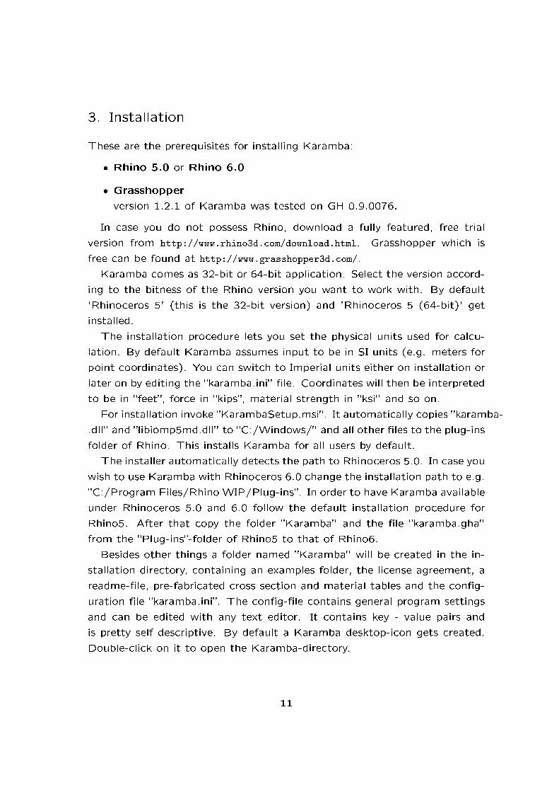
3. Installation
These are the prerequisites for installing Karamba:
� Rhino 5.0 or Rhino 6.0
� Grasshopper
version 1.2.1 of Karamba was tested on GH 0.9.0076.
In case you do not possess Rhino, download a fully featured, free trial
version from http://www.rhino3d.com/download.html. Grasshopper which is
free can be found at http://www.grasshopper3d.com/.
Karamba comes as 32-bit or 64-bit application. Select the version accord-
ing to the bitness of the Rhino version you want to work with. By default
'Rhinoceros 5' (this is the 32-bit version) and 'Rhinoceros 5 (64-bit)' get
installed.
The installation procedure lets you set the physical units used for calcu-
lation. By default Karamba assumes input to be in SI units (e.g. meters for
point coordinates). You can switch to Imperial units either on installation or
later on by editing the �karamba.ini� �le. Coordinates will then be interpreted
to be in �feet�, force in �kips�, material strength in �ksi� and so on.
For installation invoke �KarambaSetup.msi�. It automatically copies �karamba-
.dll� and �libiomp5md.dll� to �C:/Windows/� and all other �les to the plug-ins
folder of Rhino. This installs Karamba for all users by default.
The installer automatically detects the path to Rhinoceros 5.0. In case you
wish to use Karamba with Rhinoceros 6.0 change the installation path to e.g.
�C:/Program Files/Rhino WIP/Plug-ins�. In order to have Karamba available
under Rhinoceros 5.0 and 6.0 follow the default installation procedure for
Rhino5. After that copy the folder �Karamba� and the �le �karamba.gha�
from the �Plug-ins�-folder of Rhino5 to that of Rhino6.
Besides other things a folder named �Karamba� will be created in the in-
stallation directory, containing an examples folder, the license agreement, a
readme-�le, pre-fabricated cross section and material tables and the con�g-
uration �le �karamba.ini�. The con�g-�le contains general program settings
and can be edited with any text editor. It contains key - value pairs and
is pretty self descriptive. By default a Karamba desktop-icon gets created.
Double-click on it to open the Karamba-directory.
11

If all goes well you will notice upon starting Grasshopper that there is a
new category called Karamba on the component panel. It consists of ten
subsections (see �gure 2). In case you do not see any icons select �Draw
All Components� in Grasshoppers �View�-menu. The installation can be
tested by placing a Karamba �License�-component on the canvas: it should
not issue a warning or error. If not, see section 7.2 for how to solve that
issue. On Apple machines make sure to have Microsofts .NET Framework
4.0 installed.
Figure 2: Category ”Karamba” on the component panel
These are the subsections which show up in the Karamba category:
� �License�: The 'License'-component contained in here delivers informa-
tion regarding the current type of license and how to get a pro-version
of Karamba (see �g. 1).
� �Params�: containers for Karamba objects like beams, loads, models,...
� �Algorithms�: components for analyzing the structural model
� �Cross Section�: contains components to create and select cross sec-
tions for elements.
� �Ensemble�: lets you create models
� �Export�: for export of Karamba-models to RStab or Robot via DStV-
�le.
� �Load�: components for applying external forces
� �Materials�: components for the de�nition of material properties
� �Results�: for the retrieval of calculation results
12
� �Utils�: contains some extra geometric functionality that makes it easier
to handle and optimize models.
The colors of Karamba's icons have a special meaning: black or white
designates the entity or entities on which a component acts. Products of
components get referenced by a blue symbol.
Basic knowledge of Rhino and Grasshopper is needed to understand this
guide. It is recommended to download the Grasshopper Primer from the
Grasshopper web-site for introductory material on Grasshopper.
4. Quick start
4.1. Basic Example
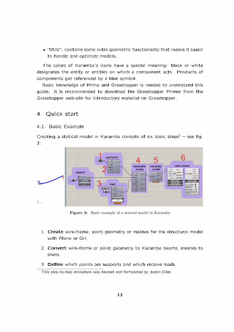
Creating a statical model in Karamba consists of six basic steps1 � see �g.
3:
Figure 3: Basic example of a statical model in Karamba
1. Create wire-frame, point geometry or meshes for the structural model
with Rhino or GH.
2. Convert wire-frame or point geometry to Karamba beams, meshes to
shells.
3. De�ne which points are supports and which receive loads.
1This step-by-step procedure was devised and formulated by Justin Diles
13

4. Assemble the Karamba structural model with points, elements, sup-
ports and loads. Optional: De�ne custom cross sections and materials
and add them as well. They reference elements either by index or user
de�ned element identi�ers.
5. Analyze the Karamba structural model.
6. View the analyzed model with the �ModelView�-component. De�ec-
tions can be scaled, multiple load cases can be viewed together or
separately. The �BeamView�- and �ShellView�-components (not shown
in �g 3) can be used to generate mesh representations of stresses, level
of material utilization,....
Karamba is intended to provide an intuitive approach to statical model-
ing. All its components come with extensive help-tags and there are lots
of examples on the web (see http://www.karamba3d.com/examples) and in the
installation folder (double-click on the Karamba desktop-icon) which can be
easily customized according to ones own needs.
4.2. Physical Units
On installing Karamba one can specify the family of physical units to be used
for input and results. The default option is metric (e.g. meters, centimeters,
degree Celsius, Newtons,...) but Karamba can also deal with Imperial units
(e.g. feet, inch, degree Fahrenheit, kiloponds,...).
The set of units to be used can be changed any time by editing the
�karamba.ini� �le.
Depending on the family of units Karamba interprets geometric input
either as meters or feet. The kind of physical units that components expect
to receive shows up in the tool-tip which appears when the mouse pointer
hovers over an input-plug.
Changing the type of physical units during the creation of a GH de�nition
may give rise to problems: The help text of Grasshopper components does
not change dynamically. Switching from SI to imperial units leaves the help
text of those components already placed on the canvas unaltered. The
interpretation of the input values however changes. Opening a GH de�nition
14

with Karamba versions with di�erently set physical units entails the same
problem.
4.3. Elements
Figure 4: Components for creating beam- (1) and shell-elements (2)
Beam- and shell-elements can be generated based on lines and meshes.
Give an �id� name for later reference (e.g. �B� and �S� in �g. 4). This
allows non-default cross sections and materials to be assigned to them. El-
ement names need not be unique. Karamba provides truss-, beam- and
shell-elements. All geometric input is assumed to be in meters when you use
SI-units and feet in case of Imperial units.
4.4. Materials
Figure 5: left: definition of a custom material (1). Right: selection of a material from thematerial library (2)
Materials can be de�ned by setting their mechanic properties. Alterna-
tively materials can be selected from a library of prede�ned materials that
comes with Karamba. The �Elems|Id� input-plug speci�es the names of the
elements to which the material shall be attached. Leaving �Elems|Id� empty
de�nes the material for all elements. Steel is the default for elements if
15

nothing is given.
4.5. Cross Sections
Figure 6: left: definition of a beam cross section (1); Middle: definition of a shell crosssection (2); Right: selection of a cross section from the default cross section library. (3)
Arbitrary I-, hollow box, �lled trapezoid and hollow circular cross sections
can be de�ned for beams, an element-wise variable height for shells. Cross
sections get attached to elements via element names (�B� and �S� in �g.
6). Alternatively cross sections can be chosen from a library.
The Karamba cross sections are available as multi-components: they can
be accessed via the single component �Cross Sections�. The drop down
menu lets you select the concrete type.
4.6. Supports
Figure 7: Component for creating supports.
Supports suppress translations or rotations at nodes. An activated button
appears black and means either zero translation (T) in the direction of the
global x-, y- or z-axis or zero rotation (R) about the corresponding global axis.
A node index or position can be used to specify the location of a support.
16

Supply a plane as input for specifying locally oriented support conditions.
4.7. Loads
Figure 8: definitions of gravity load (1), point load (2), uniformly distributed load on abeam (3) and distributed load on a mesh (4)
Fig. 8 shows examples for de�ning loads on parts of a structural model.
The input-plug �LCase� can be used to set the number of the load case
in which the load acts. This enables di�erent load scenarios (e.g. wind
from di�erent directions) to be created. Gravity loads (1) act on the whole
structure. The location of point loads (2) can be speci�ed by node index or
position. Beam loads (3) act on elements given by element identi�ers. Dis-
tributed loads on arbitrary meshes (4) get reduced to approximately statically
equivalent node and beam loads. The direction of gravity and point-loads is
given by a vector in input-plug �Vec� and refers to the global coordinate sys-
tem. The direction vector of beam- and mesh-loads can be speci�ed relative
to the global or local (relating to the element or mesh) coordinate system.
The loads can be accessed via the �Loads�-multi-component where the
concrete type is selected with the drop down menu.
4.8. Model
After de�ning elements, supports, loads and optionally cross sections and
materials the statical model can be assembled (see �g. 9). Elements get
rigidly connected in case they attach to the same node. The component
outputs the total mass of the model and its center of gravity (COG).
17

Figure 9: The model gets assembled from the generated structural information.
4.9. Algorithms
Figure 10: The model can be evaluated in several ways. Left: analysis of structural re-sponse under loads; Right: calculation of eigen-modes.
Karamba o�ers several di�erent ways of evaluating a structural model.
The �Analyze� component calculates the response of a model under external
loads. The numerical evaluation options comprise second order theory, eigen-
modes, natural vibration modes, large de�ections, evolutionary structural
optimization, cross section optimization and iterative elimination of tension
or compression elements. For each calculation option exists a corresponding
component which takes a model as input, calculates it and adds the results
to the model data.
4.10. Visualization
Karamba comes with three components for visualizing the structural model
(see �g. 11):
1. �ModelView�: Sets the basic visualization properties like scaling factor
of displacements, sizes of symbols, number of displayed load case,...
2. �BeamView�: visualizes beams
18

Figure 11: There are three components for visualizing the model: ”ModelView”,”BeamView” and ”ShellView”
3. �ShellView�: visualizes shells
Each of these components contains submenus which can be unfolded by
clicking on the black caption bar. The numerical range of sliders can be
set by double-clicking on their black knob. Visualization properties stick to
the model and stay valid until they get overruled by another downstream
visualization component.
4.11. Results
Figure 12: Retrieval of numerical results: nodal displacements (1), level of material uti-lization (2), resultant cross section forces (3) and reaction forces (4).
Structural response properties can be used to inform the model and e.g.
optimize it. Fig. 12 shows some of the available options.
19

5. Quick Component Reference
5.1. License
License: Returns the program version, license information and can be
used to manage the license �le.
5.2. Algorithms
AnalyzeThI: Calculates the de�ections of a given model using �rst
order theory.
AnalyzeThII: Calculates the de�ections of a given model using second
order theory.
Large Deformation Analysis: Does incremental geometrically non-
linear analysis for loads in load case zero.
Buckling Modes: Calculates the buckling-modes and buckling load-
factors of the given model under normal forces N II.
Eigen Modes: Calculates the eigen-modes of the given model ac-
cording to the special eigenvalue problem.
Natural Vibrations: Calculates the natural vibrations of the given
model.
BESO for Beams: Optimizes the topology of beams in a a structure
by using Bi-directional Evolutionary Structural Optimization.
BESO for Shells: Optimizes the topology of shells in a a structure
by using Bi-directional Evolutionary Structural Optimization.
Optimize Cross Section: Selects optimum cross sections for beams
and trusses in the model .
Tension/Compression Eliminator: Removes beams or trusses under
axial tension or compression. By default compression members will be
removed.
5.3. Cross Section
Cross Sections: Multi-component for creating cross sections:
20

� Box-Pro�le (default): Creates rectangular, trapezoid and tri-
angular hollow cross sections.
� Circular Hollow Pro�le: Creates circular hollow cross sections.
� I-Pro�le: Creates I-shaped cross sections.
� Shell Cross Section: Lets you set the height of a shell cross
section.
� Spring-Cross Section: De�nes the spring sti�ness of an ele-
ment.
� Trapezoid-Pro�le: Creates �lled rectangular, trapezoid and tri-
angular cross sections.
Beam-Joint Agent: Crawls around in the model and adds joints to
beams on the basis of geometric relations.
Beam-Joints: Adds hinges at the end-points of beams.
Disassemble Cross Section: Retrieves properties of a cross section.
Eccentricity on Beam: Sets the eccentricity of a cross section rela-
tive to the element axis in global coordinates.
Eccentricity on Cross Section: Sets the eccentricity of a cross sec-
tion relative to the element axis in local beam coordinates.
Modify Cross Sections: Multi-component for modifying cross sec-
tions. Works either directly on a cross section object or indirectly as
an autonomous agent:
� Modify Beam Cross Sections (default): Modi�es beam cross
sections only.
� Modify Shell Cross Sections: Modi�es shell cross sections only.
Cross Section Matcher: Returns for a cross section the best �tting
cross section contained in a given list. The matched cross section is
equal or better in all mechanical aspects at minimum weight.
21

Cross Section Range Selector: Lets you select cross sections by
country, shape, family or maximum depth or width.
Cross Section Selector: Lets you select cross sections by name,
regular expression or index from a list of cross sections.
Generate Cross Section Table: Converts a list of cross sections
into a string which can be streamed as a csv-�le and used as a cross
section table.
Read Cross Section Table from File: Reads cross section data from
a csv-�le.
5.4. Model
Activate Element: Activates the elements of a model according to
the activation list. Uses the soft kill approach for inactive elements.
Assemble Model: Creates a �nite element model by collecting given
entities (points, beams, shells, supports, loads, cross sections, mate-
rials,... ).
Connected Parts: Returns groups of interconnected lines of the
model.
Disassemble Model: Decomposes a model into its components.
Connectivity to Beam: Creates beams with default properties from
given connectivity diagram.
Index to Beam: Creates beams with default properties from given
node indexes.
Line to Beam: Creates beams with default properties from given
lines. Lines that meet at a common point are by default rigidly con-
nected with each other. Karamba assumes input to be in meter or feet.
Mesh to Shell: Creates shells with default properties from given
meshes. Quad faces are split to triangles.
Modify Element: Multi-component for modifying elements. Works
either directly on an element or indirectly as an autonomous agent:
22

� Modify Beam (default): Modi�es beams only.
� Modify Shell: Modi�es shells only.
Point-Mass: Attaches a point mass to a node of given index or po-
sition. Does not result in additional weight, only translational inertia.
Disassemble Element: Decomposes elements into their components.
Make Beam-Set: Puts beams designated by their beam identi�er
into a group.
Orientate Beam: Sets the local Z-axis of beams according to a given
vector and adds a rotation angle DAlpha [deg] about the longitudinal
axis. Flips beam direction according to a given x-vector.
Select Beam: Selects beams according to a given identi�er and puts
all incoming beams in two groups: selected or rejected. The identi�er
may be the element index, name or a regular expression.
Support: Creates supports at nodes of given node-indexes or node-
coordinates. Lets you select translations/rotations which should be
zero and the support orientation with respect to the global coordinate sys-
tem.
5.5. Export
Export Model to RStab: Exports a model to RStab5, RStab6,
RStab7, RStab8 or Robot by creating a DStV-�le.
5.6. Load
Dissemble Mesh Load: Splits a mesh-load into corresponding line-
and point-loads.
Loads: Multi-component for de�ning loads:
� Gravity (default): Creates gravity from a speci�ed direction
vector for given load-cases.
23

� Point-Load: Creates point loads at points of given index or
position.
� Imperfection-Load: De�nes imperfections for beams under nor-
mal forces N II.
� Initial Strain-Load: Sets initial axial strains on beams.
� Temperature-Load: Imposes a temperature di�erence on an
element with respect to its initial temperature at construction.
� Line-Load on Element: Creates a uniformly distributed load on
a beam.
� Mesh-Load: Creates approximately equivalent point- and line-
loads from a surface load on a mesh.
Prescribed Displacement: Prescribes displacements at nodes of given
node-indexes or node-coordinates. Select translations or rotations
which should be prescribed. For load-cases with no displacements prescribed
this will create a support.
5.7. Material
Material Properties: Sets the characteristic parameters of a material.
Material Selection: Lets you select a material by name, regular ex-
pression or index from a list of materials.
Read Material Table from File: Reads a list of materials from a
table given in csv-format.
5.8. Results
Deformation-Energy: Retrieves deformation energies of the elements
of the model.
Model View: Lets you inspect the general properties of the model.
24

Nodal Displacements: Returns nodal displacements: translation-
s/rotations in global x-, y-, and z-direction; rotations about global
x-, y- and z-axis.
Principal Strains Approximation: Approximates the principal strain
directions from the model deformation at arbitrary points.
Reaction Forces: Returns reaction forces and moments at supports.
Utilization of Elements: Multi-component that returns the utiliza-
tion of elements. �1� means 100%:
� Utilization of Beams (default): The utilization of beams is
calculated according to EC3 (see section A.6).
� Utilization of Shells: Returns the maximum Van Mises stress in
each sub-element of the shell.
Beam Displacements: Returns displacements along elements: trans-
lations/rotations in global x-, y-, and z-direction; rotations about
global x-, y- and z-axis.
Section Forces: Retrieves section forces along beams and trusses.
Resultant Section Forces: Retrieves resultant section forces of beams.
Beam View: Lets you inspect beam properties: section forces, cross
sections, displacement, utilization and stresses. Is to be plugged into
the de�nition after the ModelView-component.
Shell Line Results: Multi-component for generating line results on
shells:
� Force Flow Lines on Shells (default): Computes �ow lines for
forces in given direction at user de�ned positions.
� Isolines on shells: Creates lines that connect points of same
value for selected shell results (e.g. principal stresses, displace-
ment, utilization, cross section thickness) at user de�ned positions. Also
returns values and can thus be used for probing the shell state.
25

� Principal Moment Lines on Shells: Returns the principal mo-
ment lines that originate from user de�ned points on shells.
� Principal Stress Directions on Shells: Outputs the principal
stress directions in the center of each shell element.
Shell Vector Results: Multi-component for generating vector results
in each element of a shell:
� Principal Forces on Shells (default): Outputs the �rst and
second principal normal forces and moments in the center of each
shell element as vectors.
� Principal Stresses on Shells: Outputs the values of �rst and
second principal stress on a given layer in the center of each shell
element.
Shell forces: Outputs the values of �rst and second principal normal
forces and moments in the center of each shell element.
Shell View: Lets you inspect shell properties: displacement, utiliza-
tion, principal stresses and Van Mises stress. Is to be plugged into the
de�nition after the ModelView-component.
5.9. Utilities
Detect Collisions: Counts the number of intersections between the
model and a given mesh.
Get Cells from Lines: Creates closed cells from a graph and vertices
on a user supplied plane.
Line-Line Intersection: Intersects given lines and returns resulting
end-points and pieces.
Line-Mesh Intersection: Returns the points where given lines inter-
sect given meshes.
Mesh Breps: Takes multiple breps and generates a uni�ed mesh from
them. The algorithm takes account of common edges and prede�ned
points. This lets one de�ne positions for supports or point-loads on shells.
26

Nearest Neighbors: Connects each node of one set to a given number
of nearest neighbor nodes or neighbors within a speci�ed distance of
another set.
Multi-dimensional Nearest Neighbors: Performs a multidimensional
nearest neighbor search on a two sets of vectors.
Principal States Transformation: Transforms given principal vectors
of stresses, moments or in-plane forces to an arbitrary direction.
Remove Duplicate Lines: Eliminates identical lines.
Remove Duplicate Points: Eliminates identical points.
Element Felting: Felts elements of a model by connecting them at
their mutual closest points.
Mapper: Applies mappings (like Simple Stitch) to a model.
Interpolate Shapes: Interpolates between a base geometry (0.0) and
given shape(s) (1.0).
Simple Stitch: Multi-component for de�ning modes of connection
between sets of beams:
� Simple Stitch (default): Connects beam sets by a preset num-
ber of elements.
� Stacked Stitch: Connects beam sets by a preset number of
elements that do not intersect each other.
� Proximity Stitch: Connects beam sets by a preset number of
elements whose maximum inclination can be controlled via min/-
max o�set-limits from their starting point.
User Iso-Lines: Creates iso-lines on a model based on user supplied
nodal values.
User Stream-Lines: Creates stream-lines on a model based on user
supplied vectors at the nodes.
27

6. Component Reference
6.1. Ensemble
The subsection �Ensemble� of Karamba contains components for handling
the basic aspects of a statical model.
6.1.1. Activate Element
Figure 13: Setting the activation state of all elements of a model with a list of booleanvalues.
The activation state of an element can be controlled with the Activate
Element-component (see �g. 13). This component expects a model and
a list of boolean values as input. The list of true/false values will be
mapped to the activation status of the elements in the model. �true� corre-
sponds to �active�, �false� to inactive. Section 6.5.7 shows, how the Activate
Element-component enables one to view the solution history of the iterative
FindForcePath-algorithm.
Karamba sets elements inactive by giving them a very weak material with
zero weight.
6.1.2. Assemble Model
In order to calculate the behavior of a real world structure one needs to de�ne
its geometry, loads and supports. The component �Assemble� gathers all the
necessary information and creates a statical model from it (see �gure 14).
In case that some beams were de�ned by node indexes then these will
refer to the list of points given at the �Pt� input-plug.
28

Figure 14: The Assemble-component gathers data and creates a model from it.
The input-plug �LDist� can be used to de�ne the distance of points below
which they will be merged to one. This helps in dealing with inaccurate
geometry. Giving a negative value to �LDist� allows two separate nodes in a
model to reside on the same spot. This lets you de�ne zero length elements
such as springs connecting the two halves of a scissor structure.
The output-plug �Mass� renders the mass of the structure in kilogram,
�COG� the position of its center of gravity. When being plugged into a
panel the model prints basic information about itself: number of nodes,
elements, and so on. At the start of the list the characteristic length of the
model is given which is calculated as the distance between opposing corners
of its bounding box.
6.1.3. Connected Parts
When creating a model based on unprecise geometry or using a generative
process, elements may not be connected to each other as desired. The Con-
nected Parts-component (see �g. 15) takes a model as input and determines
its connected parts. It considers beams and trusses only. Connected groups
get listed in a data tree in descending order of group size.
29

Figure 15: The Connected Parts-component groups beams into sets of elements that haveat least on node in common each.
6.1.4. Disassemble Model
Figure 16: Model is decomposed into its components.
It is sometimes necessary to pull apart existing models in order to reassem-
ble them in di�erent con�gurations. The DisassembleModel-component can
be used for decomposing a statical model into its components (see �gure
16). Loads, supports and elements reference the nodes they connect to
by their node-index � regardless whether they were initially de�ned using
coordinates or node-indexes. This can be used to change the geometry of
a model without altering its topology: plug a list of modi�ed Grasshopper
points into the �Pt�-plug of an Assemble-component along with the objects
you get from DisassembleModel and see what happens.
30

6.1.5. Line to Beam
Figure 17 shows how Karambas LineToBeam-component takes two lines as
input, �nds out how they connect and outputs beams as well as a set of
unique points which are their end-points. Points count as identical if their
distance is less than that given in �LDist�. The default value is 0.005[m].
The LineToBeam-component accepts only straight lines as geometric input.
Therefore poly-lines and the like need to be exploded into segments �rst.
Figure 17: The LineToBeam-component that turns two lines into beams
All coordinates are in meters. In order to be of immediate use beams come
with a number of default values (see string-output in �gure 17): �active�
means that a beam will be included in the statical model. The default cross
section is a circular hollow pro�le of diameter 11.4[cm] with a wall-thickness
of 0.4[cm]. The default material is steel of grade �S235�.
Lines that fall below the length limit given by �LDist� get automatically
removed. Unless lines get removed there is a one to one correspondence
between the list of input lines and output beams. The order in which points
appear in the output node-list is random by default. However it is sometimes
advantageous to identify certain points by their list index in order to put loads
on them or to de�ne supports. This can be achieved by feeding a list of
coordinates into the �Points�-plug. They will be placed at the beginning of
the output nodes-list. So in order that the end-points of the structure in
�gure 17 have index 0 and 1 it is necessary to input a list of points with
coordinates (0/0/0) and (8/0/0).
There are four more input plugs on the LineToBeam-component:
� New: If this plug has the value �False� only those lines will be added to
the structure that start and end at one of the points given in the input
points-list.
31

� Remove: If this option has the value �True� the LineToBeam-component
checks for lines that lie on each other and merges such duplicates into
one. This prevents an error that is hard to detect by visual inspection
alone: Two lines on the same spot mean double member sti�ness in
the statical model.
� LDist: sets the limit distance for two points to be merged into one.
Lines of length less than that value will be discarded. The default value
is 5[mm].
� Id: takes a list of strings as identi�ers for beams. The default value
is an empty string. Each beam has a name by default: its zero based
index in the model. Identi�ers provide a useful means to group the
beams in order to modify or display them.
Beams that meet at a common point are by default connected rigidly in
the statical model like they were welded together. See section 6.2.4 on how
to de�ne joints at the end of beams. The �Info� output-plug informs about
the number of removed nodes and beams.
6.1.6. Index to Beam
Figure 18: The IndexToBeam-component lets you directly define the connectivity infor-mation of beams
Sometimes the initial geometry is already given as a set of points and
two lists of node-indexes with one entry for each start- and end-point of
beams respectively. In such a case it would be cumbersome to convert this
information into geometric entities only for feeding it into the LineToBeam-
component which reverses the previous step. The IndexToBeam-component
(see �gure 18) accepts a pair of lists of node-indexes and produces beams
32

with default properties from it. This speeds up model generation considerably
for there is no need to compare nodes for coincident coordinates.
The IndToBeam-component makes it possible to de�ne elements with
zero length. This proves useful in case you want to connect elements that
touch each other but should not be rigidly connected (think of a scissor �
see section 6.2.3 about springs).
6.1.7. Connectivity to Beam
In Grasshopper meshing algorithms can generate topological connectivity di-
agrams. With the help of the ConToBeam-component these may be directly
converted to beam-structures (see �gure 19).
Figure 19: The ConToBeam-component turns connectivity diagrams into sets of beams
6.1.8. Mesh to Shell
The �MeshToShell� component takes a triangle or quad mesh and turns
it into a group of shell elements (see �g. 20). Quads get automatically
decomposed to triangles. Each patch of shells can be given an identi�er for
later reference when attaching custom material or cross section properties.
Shell patches are rigidly connected when their nodes lie at a distance less
then that given in �LDist�. The �Pt� input serves the same purpose as in
the �LineToBeam�-component � see sec. 6.1.5. By default shells have a
thickness of 1[cm] and steel as their material.
The shell elements used in Karamba resemble the TRIC-element devised by
Argyris and coworkers (see [1], [2] for details). They are facetted (i.e. �at)
elements with constant strain in each layer. Karamba neglects transverse
shear deformation.
33

Figure 20: The MeshToShell-component turns meshes into shells
6.1.9. Modify Element
�Modify Element� id a multi-component which can be applied to shell-, beam-
and truss elements. Use the drop-down list at the bottom of the component
to select the type.
By default Karamba assumes the cross-section of beams to be steel tubes
with a diameter of 14.3[cm] and a wall-thickness of 0.4[cm]. When two beams
meet they are rigidly connected like they were welded together. Use the
ModifyElement-component with �Element Type� set to �Beam� to set the
beam properties according to your choice. Figure 21 shows how this can be
done. There are two variants for using the �Modify Element�-component:
1. Insert it in front of the Assemble-component and let element objects
�ow through it (see e.g. the modi�cation of beams in �g. 21). By
default the ModifyElement-component leaves all incoming elements un-
changed. Several ModifyBeam-components may act consecutively on
the same beam.
2. Create a stand-alone element-agent that can be fed into the �Elem�-
input-plug of the Assemble-component. The input-plug �ShellId� or
�BeamId� let you select the elements to be modi�ed. Use regular ex-
pressions to specify groups of elements.
6.1.10. Modify Element for Beams
These element properties can be modi�ed:
Activation status of beams
34
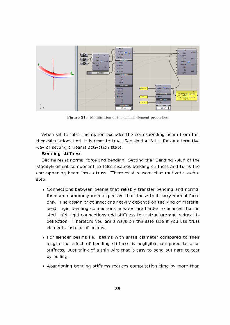
Figure 21: Modification of the default element properties.
When set to false this option excludes the corresponding beam from fur-
ther calculations until it is reset to true. See section 6.1.1 for an alternative
way of setting a beams activation state.
Bending sti�ness
Beams resist normal force and bending. Setting the �Bending�-plug of the
ModifyElement-component to false disables bending sti�ness and turns the
corresponding beam into a truss. There exist reasons that motivate such a
step:
� Connections between beams that reliably transfer bending and normal
force are commonly more expensive than those that carry normal force
only. The design of connections heavily depends on the kind of material
used: rigid bending connections in wood are harder to achieve than in
steel. Yet rigid connections add sti�ness to a structure and reduce its
de�ection. Therefore you are always on the safe side if you use truss
elements instead of beams.
� For slender beams i.e. beams with small diameter compared to their
length the e�ect of bending sti�ness is negligible compared to axial
sti�ness. Just think of a thin wire that is easy to bend but hard to tear
by pulling.
� Abandoning bending sti�ness reduces computation time by more than
35

half for each node with only trusses attached.
� Karamba bases de�ection calculations on the initial, undeformed geom-
etry. Some structures like ropes are form-active. This means that when
a rope spans between two points the deformed geometry together with
the axial forces in the rope provide for equilibrium. This e�ect is not
taken into account in Karamba. In Karamba only the bending sti�ness
of the rope (which is very small) keeps it from de�ecting inde�nitely.
One way to circumvent this lies in using a truss instead of a beam-
element. The second possibility would be to reduce the speci�c weight
of the rope to zero (see further below). The third possibility would be
to start from a slightly deformed rope geometry and apply the external
loads in small steps where the initial geometry of each step results from
the deformed geometry of the previous one (see section 6.5.3).
Trusses only take axial forces. Therefore they do not prevent the nodes
they are connected to from rotating. In case that only trusses attach to
a node, Karamba automatically removes its rotational degrees of freedom.
Otherwise the node could freely rotate which is a problem in static calcu-
lations. As soon as one beam connects to a node the node has rotational
degrees of freedom. Bear this in mind when the Analysis-component turns
red and reports a kinematic system. Transferring only axial forces means
that a truss reduces a nodes movability in one direction. A node that is
not attached to a support has three translational degrees of freedom. Thus
there must be three truss elements that do not lie in one plane for a node
to be �xed in space.
Height and wall-thickness of cross-sections
Height � which in case of circular tubes is equivalent to the outer diameter
D � and wall-thickness of a cross-section determine a beams axial and bend-
ing sti�ness. Karamba expects both input values to be given in centimeter.
The cross-section area is linear in both diameter and thickness whereas the
moment of inertia grows linearly with thickness and depends on D3 in case of
full sections and on D2 in case of hollow sections. So in case of insu�cient
bending sti�ness it is much more e�ective to increase a beams height (or
diameter) than increasing its wall thickness.
Local and Global Eccentricity of the Beam axis
36

The input-plugs �ecce-loc� and �ecce-glo� serve to set the eccentricity of
the beam-axis with respect to the connection line between its endpoints.
Both expect a three dimensional vector. �ecce-loc� refers the eccentricity
to the local, �ecce-glo� to the global coordinate system. Eccentricities of
beams can also be de�ned via the Eccent-Beam-component (see sec. 6.2.7).
Orientation of the Beam
Lets you de�ne the orientation of a beam. Works analogously to the
orientate-beam-component (see 6.1.15).
Buckling property for cross section optimization
Buckling can be turned o� for cross section optimization. This lets you
simulate pre-tensioned, slender elements without having to really pretension
them. The necessary pretension force is roughly the negative value of the
largest compressive axial normal force of all load cases.
Buckling length in local beam directions
For doing cross section optimization it is necessary to know a beams
buckling length. Karamba approximates it using the algorithm described in
section 6.5.10. For cases of system buckling this approximation does not
lie on the safe side. The input-plugs �BklLenY�, �BklLenZ� and �BklLenLT�
allow to specify the buckling length of a beam for its local Y- and Z- axis
respectively as well as for lateral torsional buckling. When speci�ed, these
values override those from the buckling length calculation of Karamba. The
value �lg� sets the distance of transverse loads from the center of shear of
the cross section. It defaults to zero. Positive values mean that the loads
point towards the shear center and thus act destabilizing for lateral torsional
buckling. The property �lg� in�uences the beams utilization with respect to
lateral torsional buckling according to EC3.
Second order theory normal force N II
Axial normal forces in�uence the sti�ness of a beam in second order theory
calculations. If compressive they lower, in case of tension they increase
its bending sti�ness. Think of a guitar string which vibrates at a higher
frequency (i.e. is sti�er) under increased tension. In Karamba the normal
force which impacts sti�ness (N II) is independent from the normal force
which actually causes stresses in the cross section (N). This enables one to
superimpose second order theory results on the safe side by choosing N II as
the largest compressive force N of each beam.
37

6.1.11. Modify Element for Shells
Height
Sets a uniform height throughout the shell.
Second order theory normal force N II
As for beams N II for shells speci�es the in-plane normal force which impact
sti�ness in case of second order theory calculations. It is a force per unit of
length assumed to be of same magnitude in all directions of the plane of the
shell.
6.1.12. Point-Mass
Figure 22: Vibration mode of beam with point mass in the middle.
Karamba is capable of calculating the natural vibration modes and fre-
quencies of structures (see sec. 6.5.6). For results to match reality the
inertia properties of a structure need to be modeled correctly. Masses of
elements (e.g. beams, trusses, shells) are automatically taken care of. All
other items need to be included via point-masses. Be aware of the fact that
masses de�ned with the �Point-Mass�-component do not have a weight but
inertia only! Thus they e�ect only the calculation of natural frequencies.
The �Point-Mass� component expects a mass in [kg] at its input-plug �Mass�
(see �g. 22). Nodes where masses shall sit can be identi�ed by supplying
node indexes or positions (just like for point-loads). Point masses get dis-
played as green spheres. Their diameters result from the volume calculated
as mass divided by density. The latter defaults to 7850[kg/m3] (steel) and
can be provided at the input-plug-�rho�.
38

Figure 23: A beam decomposed into its individual parts.
6.1.13. Disassemble Beam
When interested in the information contained in a beam component feed
it into the �DisassembleBeam�-component (see �g. 23). It is necessary to
provide the list of points that correspond to the list of nodes of the model.
This is due to the fact that beams can reference their nodes via index. The
component contains several subsections which can be unfolded by clicking
on the dark menu header.
6.1.14. Make Beam-Set
The �Make Beam-Set�-component provides a practical way for grouping dif-
ferent elements under one identi�er (see �g. 24). Beam-sets need not be
39

Figure 24: Beam-sets can be used to group beams.
disjoint. The �Beam Id� plug expects a list of strings with beam-identi�ers,
beam indexes, other beam-set-identi�ers or a regular expression. Regular
expressions have �&� as their �rst character by de�nition. �Set Id� expects
a string which serves as identi�er of the new set of beams.
The group of beams de�ned by a set can be used for de�ning geometric
mappings. In this context a beam-set represents a polygon of straight seg-
ments. The order of the elements in the set is de�ned by the order in which
they were entered into the set. Such polygons can be split at an arbitrary
position (see e.g. section 6.8.12). �MinSLen� (minimum segment length)
lets you set the minimum length which may result from such a split. In case
of potentially smaller segments the intersection point snaps to its nearest
neighbor.
In order to group a structure visually, beam-sets can be given di�erent
colors. These colors show when �Cross section� is enabled in the BeamViews
�Render Settings� (see section 6.6.8).
The identi�er of a beam-set can be used anywhere instead of a beam
identi�er. In order to be registered with the model, beam-sets need to be
fed into the �Set� input-plug of the Assemble-component.
6.1.15. Orientate Beam
In Karamba the default orientation of the local coordinate system of a beam
or truss follows these conventions:
� The local X-axis (of red color) is the beam axis and points from starting-
40

Figure 25: The orientation of the local beam coordinate system can be controlled withthe OrientateBeam-component.
node to end-node.
� The local Y-axis (green) is at right angle to the local X-axis and parallel
to the global XY-plane. This speci�es the local Y-axis uniquely unless
the local X-axis is perpendicular to the XY-plane. If this is the case,
then the local Y-axis is chosen parallel to the global Y-axis.
� The local Z-axis (blue) follows from the local X- and Y-axis so that the
three of them form a right-handed coordinate system.
The local coordinate system a�ects the direction of locally de�ned loads
and the orientation of the element's cross section. Use the �Orientate Beam�
component to set the local coordinate system (see �g. 25):
� The input plug �X-axis� accepts a vector. The local X-axis will be
oriented in such a way that its angle with the given vector is less than
90[deg]. This allows to give a consistent orientation to a group of beams.
� The local Z-axis lies in the plane which is de�ned by the local X-axis
and the vector plugged into the �Z-axis�-input.
� �Alpha� represents an additional rotation angle (in degree) of the local
Z-axis about the local X-axis.
6.1.16. Select Beam
All structural elements can be given identi�ers, i.e. names. These names
need not be unique: Two elements can have the same name without Karamba
41

Figure 26: Elements can be selected by using their identifiers.
complaining. By default an element identi�er corresponds to the elements
index. Figure 26 shows how a list of elements can be split into two data
trees using their identi�ers. The �Select Beam�-component expects a list of
elements in �Elems� as well as a list of identi�ers or regular expressions in
�Id�. Regular expressions need to be pre�xed by a �&�. They represent a
very mighty selection tool. In �g. 26 one can see three use-cases:
� �&.[1-2]�: a �.� matches any character; �[1-2]� matches one character
in the range of �1� to �2�. This is equivalent to �[12]�.
� �&b.�: matches any identi�er that starts with �b� followed by an arbi-
trary character.
� �&.[13]�: matches any identi�er that starts with an arbitrary character
followed either by �1� or �3�.
There are two output-plugs on the �Select Beam�-component: �SElem�
renders the selected elements which match the selection criteria, �RElem�
returns the rest. The entries of the �SElem� and �RElem� output data
remember their spot in the original list of elements. Joining them results in
the original order of elements.
6.1.17. Support
Without supports a structure would have the potential to freely move around
in space. This is not desirable in case of most buildings. The current version
of Karamba does statical calculations. This means that there must always
42

be enough supports so that the structure to be calculated can not move
without deforming. Thus rigid body modes are forbidden.
When de�ning the supports for a structure one has to bear in mind, that
in three dimensional space a body has six degrees of freedom (DOFs): three
translations and three rotations (see �gure 27). The structure must be
supported in such a way that none of these is possible without invoking
a reaction force at one of the supports. Otherwise Karamba will refuse
to calculate the de�ected state. Sometimes you get results from moveable
structures although you should not: The reason for this lies in the limited ac-
curacy of computer-calculations which leads to round-o� errors. Sometimes
one is tempted to think that if there act no forces in one direction � consider
e.g. a plane truss � then there is no need for corresponding supports. That
is wrong: What counts is the possibility of a displacement.
Figure 27: Metaphor for the six degrees of freedom of a body in three-dimensional space.
Bad choices of support conditions are easy to detect with Karamba: In
section 6.5.5 it is shown how to calculate the eigen-modes of a structure.
This kind of calculation works also in cases of moveable structures: rigid
body modes � if present � correspond to the �rst few eigen-modes.
Figure 28 shows a simply supported beam. The �Karamba/Ensemble/-
Support�-component takes as input either the index3 or the coordinates of
3In order to �nd out the index of a speci�c node enable the node-tag checkbox in the
ModelView-component. See section 6.1.5 on how to prede�ne the index of speci�c
nodes
43

Figure 28: Define the position of supports by node-index or position.
the point (or a list with indexes or positions of points) to which it applies.
By default the coordinate system for de�ning support conditions is the
global one. This can be changed by de�ning a plane and feeding it into the
�Plane�-input plug of the �Support� component.
Six small circles on the component indicate the type of �xation: The
�rst three correspond to translations in global x, y and z-direction, the last
stand for rotations about the global x,y and z-axis. Filled circles indicate
�xation which means that the corresponding degree of freedom is zero. The
state of each circle can be changed by clicking on it. The string output of
the component lists node-index or nodal coordinate, an array of six binaries
corresponding to its six degrees of freedom and the number of load-case to
which it applies. Supports apply to all load cases by default.
Supports cause reaction forces. These can be visualized by activating
�Reactions� in the �Display Scales� section of the ModelView (see section
6.6.2). They show as arrows with numbers in colors green � representing
forces � and purple � representing moments. The numbers either mean [kN ]
in case of forces or [kNm] when depicting moments. The orientation of the
moment arrows corresponds to the screw-driver convention: They rotate
about the axis of the arrow anti-clockwise when looked at in such a way that
the arrow head points towards the observer.
From the support-conditions in �gure 28 one can see that the structure
is a simply supported beam: green arrows symbolize locked displacements in
the corresponding direction. The translational movements of the left node
44

(a) (b)
Figure 29: Influence of support conditions – undeflected and deflected geometry. Left:Alltranslations fixed at supports. Right: One support moveable in horizontal direction.
are completely �xed. At the right side two supports in y- and z-direction
su�ce to block translational movements of the beam as well as rotations
about the global y- and z-axis. The only degree of freedom left is rotation of
the beam about its longitudinal axis. Therefore it has to be blocked at one
of the nodes. In this case it is the left node where a purple circle indicates
the rotational support.
The displacement boundary conditions may in�uence the structural re-
sponse signi�cantly. Figure 29 shows an example for this: when calculating
e.g. the de�ection of a chair, support its legs in such a way that no exces-
sive constraints exist in horizontal direction � otherwise you underestimate
its deformation. The more supports you apply the sti�er the structure and
the smaller the de�ection under given loads. In order to arrive at realistic
results introduce supports only when they reliably exist.
By default the size of the support symbols is set to approximately 1.5[m].
The slider with the heading �Support� on the ModelView-component lets
you scale the size of the support symbols. Double click on the knob of the
slider in order to set the range of values.
6.2. Cross Section
Karamba o�ers cross section de�nitions for beams, shells and springs. They
can be generated with the �Cross Sections� multi-component. Use the drop-
down list on the bottom to chose the cross section type.
45

The dimensions of each cross section may be de�ned manually or by
reference to a list of cross sections (see section 6.2.10).
Figure 30: Cantilever with four different kinds of cross section.
Cross sections are autonomous objects which can be plugged into the
Assemble-component (see �g. 30). They know about the elements (or
element sets) they belong to by their �ElemIds� property: This is a list
of strings containing element identi�ers (see 6.1.5) or regular expressions
that match a group of element identi�ers (elem-ids). Upon assembly all
elem-ids are compared to all �ElemIds� entries of a cross section. In case
of correspondence the cross section is attached to the element. An empty
string � which is the default value � signi�es that the cross section shall be
applied to all elements. If two cross sections refer to the same element then
that which gets processed later by the assemble-component wins. It makes
no sense to attribute beam cross sections to shells and vice versa � Karamba
ignores any such attempts.
6.2.1. Beam Cross Section
Karamba o�ers �ve basic types of beam cross section:
� circular tube � the default
� hollow box section
� �lled trapezoid section
46

� I-pro�le
Fig. 30 shows a cantilever with cross section properties de�ned by means
of beam identi�ers. Without eccentricities de�ned the beam axis always
coincides with the center of gravity of a cross section. Changing e.g the
upper �ange width of an I-section therefore results in a slight movement of
the whole section in the local Z-direction. In case the position of e.g. the
upper side of a cross section needs to be �xed specify an eccentricity (see
sec. 6.2.7). The corresponding position of the centroid can be retrieved
from the �Disassemble Cross Section�-component (see sec. 6.2.6).
Apart from the input-plugs that de�ne the cross section geometry there
are the �Family�- and �Name�-plug:
� �Family�: Each cross section belongs to a family. When doing cross
section optimization (see section 6.5.10), Karamba selects only pro�les
that belong to the same family as the original section. Families can be
composed of arbitrary section types.
� �Name�: the identi�er of a cross section � need not be unique. Enable
�CroSec names� in ModelViews �RenderSettings�-submenu in order to
view them.
6.2.2. Shell Cross Section
Each element of a shell can be given an individual, constant thickness by
using the �Cross Sections� multi-component set to �Shell�. Fig. 31 shows a
shell consisting of two elements. Meshes form the basis for de�ning a shell
geometry (see section 6.1.8) and specify the sequence of faces (i.e. shell
elements). The list of element thicknesses in �g. 31 corresponds to that
order. In case that there are more mesh faces than thickness speci�cations
the last value (6[cm] in this case) acts as the default value. Make sure to graft
the �Heights� input when you want to de�ne a list of shell cross sections.
Otherwise one cross section results where one would expect several.
When rendering the shell cross sections (see �g. 31) thicknesses get
linearly interpolated between the nodes. The cross section height at each
node results from the mean thickness of shell elements attached to it.
47

Figure 31: Shell made up of two elements with different thicknesses.
The input-plugs �Family� and �Name� have the same meaning as described
in section 6.2.1.
6.2.3. Spring Cross Section
Figure 32: Spring fixed at one end and loaded by a point load on the other.
Springs allow you to directly de�ne the sti�ness relation between two
nodes via spring constants. Each node has six degrees of freedom (DOFs):
three translations and three rotations. Using the �Cross Sections� multi-
component with �Cross Section� set to �Spring� lets one couple these DOFs
by means of six spring-constants. A relative movement ui,rel between two
nodes thus leads to a spring force Fi = ci · ui,rel. In this equation ui,rel stands
for a relative translation or rotation in any of the three possible directions
x, y, z, ci is the spring sti�ness. In Karamba the latter has the meaning of
kilo Newton per meter [kN/m] in case of translations and kilo Newton meter
per radiant [kNm/rad] in case of rotations. The input-plugs �Ct� and �Cr�
expect to receive vectors with translational and rotational sti�ness constants
respectively. Their orientation corresponds to the local beam coordinate
48

system to which they apply. In case of zero-length springs this defaults to
the global coordinate system but can be changed with the �OrientateBeam�-
component.
In case one wants to realize a rigid connection between two nodes the
question arises as to which spring sti�ness should be selected. A value too
high makes the global sti�ness matrix badly conditioned an can lead to a
numerically singular sti�ness matrix. A value too low results in unwanted
relative displacements. So you have to �nd out by trial and error which value
gives acceptable results.
Figure 32 shows a peculiarity one has to take into account when using
springs: They are unaware of the relative position of their endpoints. This
is why the load on the right end of the spring does not evoke a moment at
the left, �xed end of the spring.
6.2.4. Beam-Joints
Figure 33: Beam under dead weight, fixed at both supports with a fully disconnectedjoint at one end resulting in a cantilever.
A structure usually consists of a large number of load bearing elements
that need to be joined together. When rigidly connected such a joint has
to transfer three section forces (one axial force, two shear forces) and three
moments (one torsional and two bending moments). Depending on the type
of material such full connections are sometimes (e.g. for wood) hard to
achieve, costly and bulky. A solution to this problem consists in introducing
hinges.
49

Figure 33 shows a beam under dead weight with fully �xed boundary
conditions at both end-points. At the right end the joint (which is in fact
no joint any more) completely dissociates the beam from the support there.
The result is a cantilever.
The symbols for joints resemble that for supports: pink arrows represent
translational joints, white circles symbolize moment hinges. In Karamba
joints are realized by inserting a spring between the endpoint of a beam
and the node to which it connects. This necessitates su�cient support
conditions at the actual nodes to prevent them from freely moving around.
See for example the right node in �g. 33 which has to be fully �xed �
otherwise the system would be kinematic.
The �Crosec-Joint�-component allows to de�ne hinges at a beams starting-
and end-node. A list of beam-identi�ers lets you select the beams where the
joint de�nition shall apply. Filled circles mean that the corresponding degrees
of freedom represent joints. �T� stands for translation, �R� for rotation.
Feed the resulting cross-section into the �Joint�-plug of the �Assemble�-
component. The orientation of the axes of the joints corresponds to the
local coordinate system of the beam they apply to.
Sometimes the sti�ness of connections lies between fully �xed and zero.
With the input-plugs �Ct-start� and �Cr-start� it is possible to set the sti�ness
of the hinge in translation (kN/m) and rotation (kNm/rad) respectively at the
start of the element. �Ct-end� and �Cr-end� provide the same functionality
for the end-point.
In order to make the de�nition of hinges accessible to optimization the
input-plugs �Dofs-start� and �Dofs-end� can be used to set hinges at the
beams endpoints with a list of numbers. Integers in the range from '0' to
'5' signify degrees of freedom to be released in addition to those speci�ed
manually with the radio-buttons.
6.2.5. Beam-Joint Agent
The �Beam-Joint Agent� creates hinges on beams based on geometric rela-
tions. Fig. 34 shows three di�erent but equivalent possibilities for de�ning
a joint. The element or the group of elements where the joint(s) shall be
placed is set by providing a list element identi�ers at the �AtElemsIds� input-
50

Figure 34: Three different but equivalent possibilities for defining a hinge based on geo-metric relations using a ”Beam-Joint Agent”.
plug. Upon assembly the beam-joint agent crawls around in the model and
places hinges when one of the following conditions apply:
� The node on the at-element connects to an element whose identi�er is
listed in the �ToElemIds� input.
� The node on the at-element connects to a node which has a number
listed in the �ToNodeInd� input.
� The node on the at-element lies on one of the geometric items supplied
in �ToGeom�. This can be points, curves, planes, breps or meshes.
The tolerance for two geometric items touching in space is �LDist� as
de�ned on model assembly (see 6.1.2).
The meaning of �Ct�, �Cr� and �Dofs� is analogous to that of the Beam-
Joints-component.
6.2.6. Disassemble Cross Section
In some cases (e.g. after optimizing cross sections) it may be necessary
to retrieve the properties of a cross section. Use the �Disassemble Cross
Section�-component for that (see �g. 35). Unfold the component sub-
sections by clicking on the dark section headers.
6.2.7. Eccentricity on Beam, Eccentricity on Cross Section
Cross section forces of beam and truss elements relate to the line that con-
nects the cross section centroids. When a cross section changes, chances are
51

Figure 35: Properties of a given cross section can be retrieved via the ”Disassemble CrossSection”-component.
Figure 36: Beam positioned eccentrically with respect to the connection line of its twoend-nodes.
high that also the position of its centroid shifts. In case of elements predom-
inantly loaded by bending moments, such a shift can normally be neglected.
In the presence of normal forces however � e.g. when considering columns �
changes in the centroids position lead to additional bending moments that
may be decisive for a members cross section design.
In Karamba there exist two components that can be used to take care
of eccentricities (see �g. 36): One works on beams, the other on cross
sections. When both variants of de�nition coincide for an element then they
52

get additively combined. This enables one to de�ne families of cross sections
of di�erent size with e.g. the position of their upper sides at one level.
The de�nition of a local eccentricity for cross sections with a �Eccent-
CroSec�-component is straight forward: The �ecce-loc�-input plug expects a
vector that de�nes the o�set with respect to the local beam axes. Values
are expected in centimeters. �x� represents the longitudinal beam axis, �y� is
horizontal, �z� vertically upwards. Cross sections with eccentricities can be
stored in cross section tables using the �GenCSTable�-component and thus
be made reusable in other projects.
The �Eccent-Beam�-component has one additional input-plug as compared
to the cross section variant: �ecce-glo� lets one de�ne beam eccentricities
([cm]) with respect to the global coordinate system.
6.2.8. Cross Section Matcher
Figure 37: The ”Cross Section Matcher”-component returns a standard profile for acustom profile.
Use the �Cross Section Matcher�-component in case you want to �nd the
�rst pro�le from a given list that provides equal or higher resistance compared
to a given custom pro�le (see �g. 37). The �CSMatch�-component takes a
cross section and a list of cross sections as input. Traversing the list starting
from the �rst element it proceeds until an appropriate pro�le is found which
is returned as the result.
53

6.2.9. Cross Section Range Selector
The cross section library that comes with Karamba contains roughly 6000
pro�les. In order to reduce the amount of information the list can be short-
ened by applying selection criteria on it using the �Cross Section Range
Select� component (see �g. 38). The input-plugs �maxH� and �maxW� let
you limit the list according to maximum cross section height and width. The
submenu which unfolds when clicking on the black �select�-bar o�ers further
options for narrowing the search: country of origin, general shape and family
name.
In case one does not supply a list of cross sections at the �CroSec� input-
plug, the cross section table that comes with Karamba is used by default.
Figure 38: Selection of a range of cross sections from among a given list.
6.2.10. Cross Section Selector
The component �CroSecSelect� deals with selecting cross sections by name
or index from a list of cross sections. Provide the name(s) or index(es) of
desired cross sections in the �Name|Ind� plug. Cross section names are not
case sensitive. All characters coming after �#� count as remark. It is possible
to use regular expressions for selection. In this selection is case sensitive and
�&� has to be provided as �rst character. List indexes start from zero.
�CroSecSelect� lets you specify beams via the �Elems|Ids�-plug which shall
be assigned a speci�c cross section. The �Assemble�-component sets the
54

Figure 39: Cantilever with four different kinds of cross section taken from the standardcross section table.
cross-sections of elements accordingly.
In case one does not supply a list of cross sections at the �CroSec� input-
plug, the cross section table that comes with Karamba is used by default.
6.2.11. Generate Cross Section Table
An entry in a cross section table consists of a row which contains:
� �country�: country of origin
� �family�: name of the group to which the cross section belongs (see
sec. 6.2.1)
� �name�: name of the speci�c cross section (see sec. 6.2.1)
� a �shape� �eld which de�nes the basic cross section type:
� �I�: I-section
� �[]�: hollow box section
� �V�: trapezoid, �lled section
� �O�: circular tube
� �S�: spring
� �Sh�: shell
� geometric properties which are used for drawing the cross section
� area, moments of inertia, etc. that de�ne the cross sections mechanical
behavior.
55

The �GenCSTable�-component takes a cross section (or a list of cross sec-
tions) as input and returns the equivalent table data as a string. The physical
units used for output are always metric. When plugged into a panel the in-
formation can be streamed to a �le which then constitutes a valid cross
section table. Karamba reads the data of cross section tables only once. So
in order that changes in the table take e�ect restart Grasshopper.
Figure 40: Transformation of a list of cross sections to a cross section table.
6.2.12. Read Cross Section Table from File
Figure 41: List of cross sections generated from the standard cross section table.
Prede�ned cross sections stored in a csv-database can be used to gener-
ate lists of cross sections via the �ReadCSTable�-component (see �g. 41).
It works along the same lines as the �ReadMatTable� (see section 6.3.3)
component. When given no path to a valid csv-table �ReadCSTable� uses
the cross section table that comes with Karamba and is situated in �.../-
Grasshopper/Libraries/Karamba/CrossSectionValues.csv�. This table con-
tains de�nitions for a range of standard steel pro�les. Use a text editor or
OpenO�ce to view or extend the table. �#� is used to mark the rest of
a line as comment. The physical units are always assumed to be metric �
56
irrespective of the user settings at installation.
When opening the �Karamba�-folder you will �nd three di�erently named
cross section tables: �CrossSectionValues.csv� and �CrossSectionValues_sorted-
ForHeight.csv� contain cross sections sorted according to increasing height.
In �CrossSectionValues_sortedForWeight.csv� the area and thus weight per
unit of length determines a cross sections relative position within a family.
When doing cross section optimization (see section 6.5.10) those two sorting
options lead to di�erent results. Depending on external requirements they
result in structures of minimum cross section height or structural weight.
6.3. Material
There are two ways for de�ning materials in Karamba: Either select a ma-
terial by name from a list of materials (see section 6.3.2) or set mechanical
material properties manually (see below).
The Appendix (see section A.1) contains additional information on me-
chanical properties of materials.
Materials (like cross sections) are autonomous entities which may be
plugged into the �Assemble� component. They know about the elements
(or element sets) they apply to by their �Elems|Ids� property: This is a list
of strings containing element identi�ers (see 6.1.5) or regular expressions
that match a group of element identi�ers (element-ids). Upon assembly
each element-id is compared to all �Elems|Ids� entries of a material. In case
they match the material is attached to the element. An empty string �
which is the default value � signi�es that the material shall be applied to all
elements.
6.3.1. Material Properties
The component �MatProps� lets one directly de�ne material properties (see
�g. 42):
� �Elems|Ids�: list of identi�ers of elements or a regular expression that
depicts the elements that shall have the speci�ed material
� Young's Modulus �E� [kN/cm2]
57

Figure 42: The definition of the properties of two materials via the MatProps compo-nent, selection of the second Material from the resulting list (mid, bottom) or selectionfrom the default material table (mid, top).
� Shear modulus �G� [kN/cm2]
� speci�c weight �gamma� [kN/m3]
� coe�cient of thermal expansion �alphaT� [1/◦C]
� yield stress �fy� [kN/cm2]
� the name of the material in �Name�
The yield stress characterizes the strength of a material. The utilization of
cross sections as displayed by the BeamView (see section 6.6.8) is the ratio
of actual stress and yield stress. In case of shells, utilization is determined
as the ratio of Van Mises Stress and yield stress (see section 6.6.15). Cross
section optimization (see section 6.5.10) also makes use of the materials
yield stress.
In case of temperature changes materials expand or shorten. �alphaT�
sets the increase of strain per degree Celsius of an unrestrained element.
For steel the value is 1.0E − 5 (1.0E − 5 = 1.0 · 10−5 = 0.00001). Therefore an
unrestrained steel rod of length 10[m] lengthens by 1[mm] under an increase of
temperature of 10◦C. �alphaT� enters calculations when temperature loads
are present.
In order to be registered with the model the resulting material needs to
be plugged into the �Assemble Model�-component.
58

6.3.2. Material Selection
The �MatSelect�-component in the menu subsection �Material� lets you se-
lect a material by family, name or index from a given list of materials (see
�g. 42 or �g. 44). Input the list of materials via the plug �Mat�. In case no
list of materials is supplied the material table that comes with Karamba is
used.
The input-plug �Name|Ind� expects either the zero-based list index of the
selected material or its name. The names of materials are not case sensitive.
A �#� in a material name means that the rest of the line is a comment. �&�
starts a regular expression � in that case material names are case sensitive.
For quick access materials may be selected via the drop down lists �Family�
and �Name�, which unfold when clicking on the components �Select� bar.
These two entries serve as additional criteria which act on the list of materials
selected through the �Name|Ind� input.
6.3.3. Read Material Table from File
Figure 43: Partial view of the default data base of materials. SI units are used irrespec-tive of user settings. Automatic conversion ensures compatibility with Imperial units.
Karamba comes with a table of prede�ned materials. The csv-�le �Ma-
terialproperties.csv� resides in the �Karamba�-folder inside the installation
directory . By default the �ReadMatTable�- component takes this �le and
creates a list of materials from it. These are available at the output-plug
�Material�. The data-base currently holds properties for �steel�, �concrete�,
�wood� and �aluminum�. There exist di�erent types of steel, concrete etc..
The generic term �concrete� will result in the selection of an everyday type
of concrete - a C25/30 according to Eurocode. More speci�c descriptions
may be given: Have a look at the data-base in order to get an overview.
Material properties speci�ed via table are assumed to be in SI units. They
59

get automatically converted when used in the context of Imperial units.
The extension .csv stands for �comma separated value�. The �le can
be opened with any text editor and contains the table entries separated by
semicolons. It is preferable however to use OpenO�ce or Excel (both can
read and write csv-�les): They render the data neatly formatted (see �g.
43). Make sure to have a �.� and not a �,� set as your decimal separator.
In some countries �.� is used to separate thousands which then needs to be
adapted as well. The setting may be changed under Windows via �regional
settings� in �system settings�. All lines in the table that start with �#� are
comments. Feel free to de�ne your own materials. All physical units in the
table are assumed to be metric irrespective of the user choice at installation.
The �le path to the materials data-base can be changed in two ways: �rst
right-click on the component and hit �Select �le path to material de�nitions�
in the context menu that pops up. Second plug a panel with a �le path into
�Path�. Relative paths are relative to the directory where your de�nition lies.
Figure 44: List of materials resulting from the ”ReadMatTable”-component reading thedefault data base of materials. Selection of the default ”Steel” via ”MatSelect”.
6.4. Load
Currently Karamba supports these types of loads: gravity-, point-, imperfection-
, pretension-, temperature-, uniformly distributed-, mesh-loads and prescribed
displacements at supports. An arbitrary number of point-, mesh-, etc.-loads
and one gravity-load may be combined to form a load-case of which again an
arbitrary number may exist. Figure 45 shows the de�nition of loads with the
60

help of the �Loads� multi-component. On the bottom of the ModelView-
component (see section 6.6.2) there is a drop-down-list (unfold it by click-
ing on the �Load-case Selection�-menu header) which can be used to select
single load-cases for display. Select ��all�� in order to view all existing load-
de�nitions of all load-cases simultaneously. Use the force-slider to scale the
size of the load-symbols (double-clicking on its knob lets you change the
value range and its current value).
Figure 45: Simply supported beam with three loads and three load-cases.
6.4.1. Gravity
It is the default setting when you place a �Loads�-component on the canvas.
Each load case may contain zero or one de�nition for the vector of gravity.
In this way one can e.g. simulate the e�ect of an earthquake by applying
a certain amount of gravity in horizontal direction. For Vienna which has
medium earthquake loads this amounts to approximately 14% of gravity that
a building has to sustain in horizontal direction. In areas with severe earth-
quake loads this can rise to 100% (this however also depends on the sti�ness
properties of the structure and underlying soil).
Gravity applies to all active elements in the statical model for which gamma
(see section 6.3.1) is not zero. The gravity vector de�nes the direction in
which gravity shall act. A vector of length one corresponds to gravity as
encountered on earth.
61

6.4.2. Point-Load
The component �Point-Load� lets you de�ne loads on points. These get
attached to their points either by node-index6 or coordinate. Feed a cor-
responding list of items into the �Pos|Ind�-plug (quite analogous to the
Support-component). A point-loads can be either a forces (kN) or mo-
ments (kNm). Feed a force- or moment-vector into the �Force� or �Moment�
input-plug. Its components de�ne the force or moment in global x-, y- and
z-direction.
When set to �true� the boolean input �Local?� makes loads and moments
follow the nodal rotations in large displacement calculations (see section
6.5.3).
Plugging a point-load into a panel component gives the following informa-
tion: Node-index where the load gets applied, force-vector, moment vector,
the number of the load case to which it belongs and whether the load is tied
to the nodal coordinate system.
By default point loads will be put into load case zero. Any positive number
fed into the �LCase�-plug de�nes the load case to which the corresponding
load will be attributed. A value of −1 signals that the load acts in all existing
load cases.
For more information on loads and some typical values see section A.2.
6.4.3. Imperfection-Load
The exists no such thing as an ideally straight column positioned perfectly
vertical. The deviation of a real column from its ideal counterpart is called
imperfection. This term comprises geometric and material imperfections.
The �Imperfection� variant of the �Loads� multi-component allows to
specify geometric imperfections. �psi0� takes the vector of the initial in-
clination of the beam axis about the axes of the local element coordinate
system in radians. With �kappa0� one can specify the initial curvature.
Imperfection loads do not add directly to the beam displacements. They
act indirectly and only in the presence of a normal force N II. An initial
6In order to �nd out the index of a speci�c node enable the �node tag�-checkbox in the
ModelView-component. See section 6.1.5 on how to prede�ne the index of speci�c nodes
or node-position
62

inclination ψ0 causes transverse loads ψ0 ·N II at the elements endpoints. An
initial curvature κ0 results in a uniformly distributed line load of magnitude
κ0 ·N II and transverse forces at the elements endpoints that make the overall
resultant force zero. For details see e.g. [4].
6.4.4. Initial Strain-Load
Karamba lets you de�ne axial initial strains. Fig. 46 shows a beam with
both ends �xed, subject to a positive initial strain. The unit of dimension
of the pretension which gets fed into the �Eps0� plug is [mm/m]. A positive
value means that the element would become longer if unconstrained.
Applying initial strain to an element is not the same as applying a pair of
opposite forces at its endpoints: In case of initial strain the axial force in
the element depends on its boundary conditions: If the structure to which
it connects is very sti� then the resulting axial force will be N = −ε0 · A · E.In �gure 46 the supports are rigid, the elements cross section A = 25[cm2],
Young's Modulus E = 21000[kN/cm2] and ε0 = 0.00015. This results in an
axial force of N = −78.75[kN ] and shows up as horizontal support reactions.
When the rest of the structure does not resist, then a pretension-load merely
results in lengthening or shortening the corresponding element.
The input plug �ElemIds� de�nes the elements where the load acts and
�LCase� the load-case.
Figure 46: Member under initial strains fixed at both ends and resulting support reac-tions.
63

6.4.5. Temperature-Load
The de�nition of temperature loads works analogously to de�ning pretension
loads (see sec. 6.4.4). The coe�cient of thermal expansion (see section
6.3.1) characterizes the response of a material to temperature changes.
Figure 47: Temperature load on a member which is fixed at both ends.
6.4.6. Line-Load on Element
Figure 48 shows a tilted structure consisting of three beams under the action
of a uniformly distributed load at elements �0� and �2�. The load acts parallel
to the beams local z-axis. The components of the load vector are assumed
to be given in kilo Newton per meter [kN/m]. The input-plug �BeamIds�
receives a list of the identi�er of the beams on which the load shall act. See
section 6.1.5 for how to attach identi�ers to beams. By default beams are
named after their index in the FE-model. There are three options for the
orientation of the load: �local to element�, �global� and �global proj.�. Their
meaning corresponds to the options available for mesh-loads (see �g. 51).
The input-plug �LCase� which designates the load case defaults to �0�.
6.4.7. Mesh-Load
The Mesh-load-component can be used to transform surface loads into equiv-
alent node- or element-loads. This lets you de�ne life-loads on �oor slabs,
moving loads on bridges (see example �Bridge.ghx� in the examples collec-
tion on the Karamba web-site), snow on roofs, wind-pressure on a facade,
etc.. Figure 49 left side shows a simply supported beam and a mesh which
consists of two rectangular faces. Each face covers one half of the beam
and has a width of 2[m] perpendicular to the beam axis. With a distributed
64

Figure 48: Line loads on a structure consisting of three beam elements defined in localbeam coordinate systems.
load of 1[kN ] in negative global Z-direction a uniformly distributed load of
2[kN/m] results.
Figure 49: Simply supported beam loaded with line loads that approximate a given,evenly distributed surface load on a mesh.
With the input-plug �BeamIds�, groups of elements can be speci�ed on
which equivalent loads shall be generated. By default all beams of the
model are included. In case no beam loads shall be included uncheck the
�Line loads� button on the �Generation� submenu.
In order to de�ne structure nodes where equivalent point-loads may be
generated, plug a list of their coordinates into the �Pos�-plug. These need
to correspond to existing nodes � otherwise the Assembly-component turns
red. O�ending nodes will be listed in its run-time error message. By default
all points of the structure are included. Uncheck �Point loads� to avoid
point-loads.
65

The procedure for calculating nodal loads and uniformly distributed beam
loads from surface loads consists of the following steps: First Karamba
calculates the resultant load on each face of the given mesh. Then the
resultant load of each face gets evenly distributed among its three or four
vertices.
The second step consists of distributing the vertex-loads among the nodes
of the structure. In order to arrive at beam loads additional helper-nodes
along their axes get generated. The mutual distance of those is chosen equal
to a third of the mean edge length of the given mesh.
Each mesh vertex transfers its load to the nearest node. In case that there
are several nodes within a radius of less than �LDist� as set at the Assemble-
component (see section 6.1.2) the vertex load gets evenly distributed among
them. The loads received by the helper-nodes along beam axes get summed
up and divided by the element length. This results in the approximately
equivalent uniformly distributed load which is placed on the element. From
the procedure described, one can see that a crude mesh may lead to a locally
incorrect distribution of loads. In the system shown in �g. 49 the points
closest to the vertices are the element's end-points. Therefore the helper
nodes along the beam-axis do not receive a share in the mesh-load and thus
no line-load results.
Fig. 50 shows a similar setting as in �g. 49. The di�erence lies in the
re�ned mesh with more vertices along the beam axis. Now loads from the
mesh vertices get distributed also to the helper nodes along the element axis.
This leads to to the generation of a uniform line-load.
The right side of �gure 50 shows what data the Mesh-load-component
collects: The input-plug �Vec� expects a vector or list of vectors that de�ne
the surface load. Its physical units are kilo Newton per square meter (kN/m2).
The orientation of the load-vector depends on the checkbox selected under
�Orientation� (see also �gure 51):
� �local to mesh�: X-component of the force vector is at right angle to
the mesh-face; the Y-component acts horizontally if the mesh-face X-
axis is not parallel to the global Z-axis. Otherwise the Y-component
of the force is parallel to the global Y-axis. This means a surface load
with components only in X-direction acts like wind pressure.
66
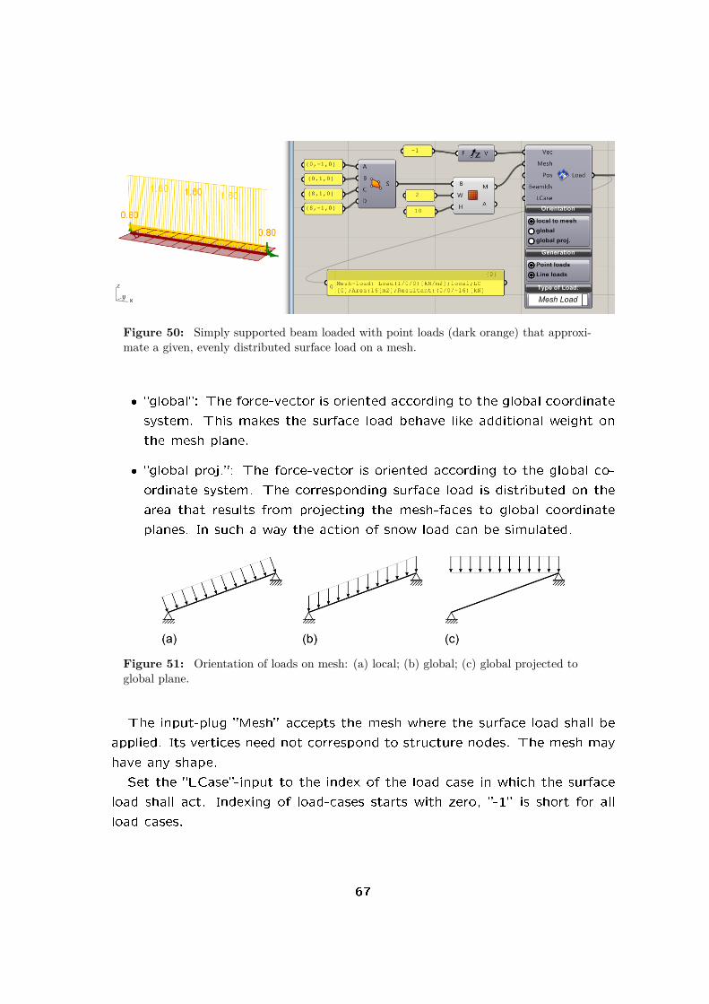
Figure 50: Simply supported beam loaded with point loads (dark orange) that approxi-mate a given, evenly distributed surface load on a mesh.
� �global�: The force-vector is oriented according to the global coordinate
system. This makes the surface load behave like additional weight on
the mesh plane.
� �global proj.�: The force-vector is oriented according to the global co-
ordinate system. The corresponding surface load is distributed on the
area that results from projecting the mesh-faces to global coordinate
planes. In such a way the action of snow load can be simulated.
Figure 51: Orientation of loads on mesh: (a) local; (b) global; (c) global projected toglobal plane.
The input-plug �Mesh� accepts the mesh where the surface load shall be
applied. Its vertices need not correspond to structure nodes. The mesh may
have any shape.
Set the �LCase�-input to the index of the load case in which the surface
load shall act. Indexing of load-cases starts with zero, �-1� is short for all
load cases.
67

6.4.8. Prescribed displacements
Supports as described in section 6.1.17 are a special case of displacement4
boundary conditions: They set the corresponding degree of freedom of a
node to zero. The more general PreDisp-component lets you preset arbitrary
displacements at nodes. Figure 52 shows a beam with prescribed, clockwise
rotations at both end-points.
The PreDisp-component resembles the Support-component to a large de-
gree: Nodes where displacement conditions apply can be selected via node-
index5 or nodal coordinates. The �Plane�-plug can be used to de�ne an
arbitrarily oriented coordinate system for the application of support condi-
tions.
Input-plug �LCase� lets you set the index of the load-case in which dis-
placements shall have a speci�ed value. The default value is �-1� which
means that the displacement condition is in place for all load-cases. It is not
possible to have displacement boundary conditions active in one load-case
and completely disabled in others: For load-cases not mentioned in �LCase�
the PreDisp-component will act like a simple support with �xed degrees of
freedom equal to zero.
Figure 52: Left: Deflection of a beam under predefined displacements at its end-supports;Right: PreDisp-component for setting displacement condition at left support.
The �Trans�- and �Rot�-input-plugs expect vectors. They de�ne nodal
translations and rotations either in global coordinates or in the coordinate
4The term �displacement� as used throughout this manual includes translations and rota-
tions.5In order to �nd out the index of a speci�c node enable the �node tag�-checkbox in the
ModelView-component. See section 6.1.5 on how to prede�ne the index of speci�c nodes
68
system de�ned by the plane fed into the �Plane�-input plug. Translations
are to be given in meter, rotations in degree. The X-component of the
rotation vector describes a rotation about the coordinate systems X-axis.
A positive value means that the node rotates counter-clockwise if the X-
axis points towards you. Analog de�nitions apply to rotations about the
Y- and Z-axis. Karamba is based on the assumption of small de�ections.
Thus be aware that large prescribed displacements and rotations give rise
to incorrect results (which can nevertheless be used for shape-�nding). For
approximating e�ects due to large displacements see section 6.5.3.
Displacements can only be prescribed if the corresponding displacement
degree of freedom is removed from the statical system. This means you
have to activate the corresponding button in the Conditions-section of the
PreDisp-component. The �rst three buttons stand for translations the last
three for rotations. Only those components of the �Trans�- and �Rot�-vectors
take e�ect which correspond to activated supports.
6.5. Algorithms
6.5.1. Analyze Th. I
With geometry, supports and loads de�ned the statical model is ready for
processing. The AnalyzeThI-component computes the de�ection for each
load case and adds this information to the model. It assumes that the
in�uence of axial forces is negligible thus �ThI� which stands for �rst order
theory. Whenever the AnalyzeThI-component reports an error (turns red)
despite the fact that the Assemble component works, it is probably a good
idea to check the support conditions.
Figure 53 shows a de�ected beam with two load-cases. An axial load acts
in load-case zero, a transverse load in mid-span in load-case one.
The analysis component not only computes the model de�ections but
also outputs the maximum nodal displacement (in meter), the maximum
total force of gravity (in kilo Newton, if gravity is set) and the structures
internal deformation energy of each load case - see section 6.6.1 for details
on work and energy.
These values can be used to rank structures in the course of a structural
69

Figure 53: Deflection of simply supported beam under single load in mid-span and axial,compressive load.
optimization procedure: the more e�cient a structure the smaller the max-
imum de�ection, the amount of material used and the value of the internal
elastic energy. Real structures are designed in such a way that their de-
�ection does not impair their usability. See section A.3 for further details.
Maximum de�ection and elastic energy both provide a benchmark for struc-
tural sti�ness yet from di�erent points of view: the value of elastic energy
allows to judge a structure as a whole; The maximum displacement returns
a local peak value.
In order to view the de�ected model use the ModelView-component (see
section 6.6.2) and select the desired load case in the menu �Load case
Selection�. There exist two options for scaling the de�ection output. First
there is a slider entitled �Deformation� in the menu �Display Scales� that lets
you do quick �ne-tuning on the visual output. Second option: the input-
plug �LC-Factor� which accepts a list of numbers that ModelView uses to
scale the loads. Its default value is 1.0. Each item in the list applies to
a load case. If the number of items in this list and the number of load
cases do not match then the last number item is copied until there is a one
to one correspondence. The second option for scaling displacements can
be used in the course of form-�nding operations: The model-plug at the
right side of the ModelView outputs the displaced geometry which can be
used for further processing. Selecting item ��all�� on the drop-down-list for
the selected load case results in a superposition of all load cases with their
corresponding scaling factor.
Looking at �gure 53 one immediately notices that only beam center
70
axes are shown. In order to see beams or shells in a rendered view add a
�BeamView�- or �ShellView�-component after the ModelView. See sections
6.6.8 and 6.6.15 for details.
6.5.2. Analyze Th. II
Axial forces in beams and in-plane forces in shells in�uence the structures
sti�ness. Compressive forces decrease a structure's sti�ness, tensile forces
increase it. The in�uence of compressive forces on displacements and cross
section forces may be neglected as long as their absolute value is less than
10% of the buckling load.
Karamba lets you consider second order theory (Th.II) via the AnalyzeThII-
component. It is based on small displacements and takes account of axial
forces via the element's geometric sti�ness matrix. For beams the procedure
outlined in [4] gets used for calculating cross section forces.
In Karamba distinction is made between normal forces Nx which cause
stresses in the members and normal forces N II which result in second order
e�ects (see also [4]). At �rst sight this concept seems weird. How can there
be two kinds of normal forces in the same beam? Well, in reality there can't.
In a computer program it is no problem: stresses get calculated as σ = Nx/A
and N II is used for determining second order e�ects. The advantage is, that
in the presence of several load-cases one can chose for each element the
largest compressive force as N II. This gives a lower limit for the structures
sti�ness. A reevaluation of the load-cases using these N II values leads to a
structural response which is too soft. However the di�erent load-cases may
then be safely superimposed.
In a model N II can be set using the ModifyBeam-component (see 6.1.9).
In such a case �0� has to be supplied at the �MaxIter�-input plug of the
AnalyzeThII-component. Otherwise N II will be determined in the course
of the iterative procedure. The value of N II can be displayed via the
ModelView-component (see 6.6.2).
Fig. 54 shows the same system as in �g. 53. This time with results
according to �rst and second order theory. When comparing the transverse
de�ections in load-case two one can see that the maximum de�ection in-
creased from 0.24[m] to 0.28[m] due to the e�ect of the axial compressive
71

load.
Figure 54: Deflection of simply supported beam under single load in mid-span and axialcompressive load. Comparison of first and second order theory results.
The AnalyzeThII-component features the following input-plugs:
�Model� Model to be considered.
�LC� Number of load-case from which to take the normal force N II in the
members which cause second order theory e�ects. If set to �-1� the
minimum normal force of all load-cases is considered.
�RTol� The determination of N II is a non-linear process. The value of �RTol�
is the upper limit of displacement increments from one iteration to the
next.
�MaxIter� Supply here the maximum number of iterations for determining
N II. The default is 50. In case �RTol� can not be reached within the
preset number of iterations the component turns orange. When N II is
known and set via e.g. the ModifyBeam-component (see 6.1.9) make
sure to feed �0� into �MaxIter�. otherwise N II will be overwritten by
the iterative procedure.
�NoTenNII� Tension forces increase the sti�ness of a statical system. When
calculating the global buckling load-factor for e.g. grid-shell this can
lead to negative values. Setting �NoTenNII� to �True� limits N II to
non-positive values.
The normal forces N II get attached to the model and will be considered
in all further analysis steps.
72

In case that N II lies beyond the buckling load an error will result. If
that happens reduce the normal forces in your structure and determine the
buckling load factor using the �Buckling Modes�-component.
6.5.3. Analyze Large Deformation
Before the advent of digital modeling people like Heinz Isler or Antoni Gaudi
helped themselves with physical models for generating curved geometries.
A popular method was to use the shape of meshes or elastic membranes
hanging from supports (see �g. 55).
(a) (b)
Figure 55: Hanging models. Left: Model of Antoni Gaudi for the Temple Expiatori de laSagrada Família (from the internet). Right: Some of Heinz Islers hanging models (from theinternet).
In Karamba the behavior of hanging models can be simulated with the
help of the �Analyze Large Deformation�-component. Figure 56 shows a
geometry derived from an initially �at mesh under evenly distributed point-
loads. Karamba handles geometric non-linearity by an incremental approach:
All external loads get applied in steps. After each step the model geometry
updates to the de�ected state. The more and the smaller the steps the
better the approximation of geometric non-linearity. The purely incremental
method however incurs an unavoidable drift from the exact solution. For
form-�nding this error should be negligible in most cases.
Figure 57 shows a simply supported beam under the action of uniformly
distributed point loads. Due to its slenderness axial sti�ness by far outweighs
bending sti�ness. Thus the de�ected shape corresponds to a string under
self weight.
The �LaDeform� component has four input-plugs:
73

Figure 56: Structure resulting from large deflection analysis with the ”LaDeform”-component.
Figure 57: Catenary resulting from point loads that do not change their direction whendisplaced.
�Model� : Model to be deformed. �LaDeform� uses load-case �0� for calcu-
lating the de�ected shape.
�Inc� : Number of increments for applying the loads
�MaxDisp� : Maximum displacement to be reached in meter [m]. When
supplied with a value the incremental de�ection in each step is scaled
to MaxDisp/Inc. This enables Karamba to handle problems with overly
large de�ections at the beginning of the incremental procedure. Think
of an initially straight string: Due to its negligible bending sti�ness it
tends to deform tremendously in the �rst loading step.
With no value supplied in �MaxDisp� external loads get incremented
74

proportionally in each step. Aside from cases like mentioned above this
results in an approximation of the structures �real� de�ections under
the given loads.
In �g. 57 the point loads are de�ned with respect to the global coordinate
system: The input-plug �Local?� at the point-load component is set to
�false�. Fig. 58 shows what happens if one changes that property to �true�:
The point-loads co-rotate with the points they apply to. This leads to a
pneumatic shape. The same happens for locally de�ned line-loads.
Figure 58: Pneumatic form resulting from point loads that rotate along with the pointsthey apply to.
The two output plugs of the �LaDeform�-component supply the de�ected
model and the maximum de�ection reached in the calculation.
The local coordinate system of each element gets updated along with its
positions. By default an elements local Y-axis is taken parallel to the global
X-Y-plane. If an element reaches a vertical position however, its default
coordinate system �ips � the Y-axis is then taken parallel to the global
Y-axis. This may lead to unwanted results when using line-loads which �ip
along with the local coordinate system. It is possible to avoid this by de�ning
local axes via the �OrientateBeam�-component.
In each incremental step the internal forces of the previous step get cleared.
This is the reason why the resulting, de�ected model contains no information
regarding internal forces.
6.5.4. Buckling Modes
Axial forces in beams and trusses as well as in-plane forces in shells change
the elements response under transverse load. Tension makes them sti�er,
compression has a softening e�ect.
75

Figure 59: Shape and load-factors of the first buckling mode of a cantilever analyzed as abeam and shell.
Slender columns or thin shells may fail due to buckling before the stresses
in the cross section reach the material strength. Stability analysis therefore
plays an important role in structural design.
When doing cross section optimization with the �Optimize Cross Section�-
component the design formulas applied take account of buckling, based on
the buckling length of the members. By default local buckling of individual
elements is assumed. So called global buckling occurs if a structural sub-
system consisting of several elements (like e.g. a truss) loses stability. Global
buckling can be checked with the �Buckling Modes�-component (see �g. 59).
The �Buckling Modes�-component expects these input parameters:
�Model� : Structure with second order normal forces N II de�ned. These
forces can either be taken from a second order theory calculation (like
in �g. 59) or speci�ed via a ModifyBeam-component.
�FromInd� : Index of the �rst buckling mode to be determined. The default
is �1�. This is also normally the only buckling shape of interest since it
corresponds to the mode of failure.
�NModes� : Number of buckling modes to be calculated. The default is �1�.
�MaxIter� : The determination of the buckling modes is an iterative proce-
dure. �MaxIter� sets the maximum number of iterations.
�Eps� : Represents the convergence criteria. For convergence the iterative
change of the norm of the displacements needs to fall below that value.
76

For the determination of buckling modes a so called Van Mises iteration
is applied. This procedure works well in case the buckling load factors are
nicely separated. Sometimes it occurs, that the load factors of the �rst
buckling shapes are identical or nearly the same. In such cases convergence
may prove hard or impossible to reach. Sometimes it helps to increase the
maximum number of iterations or the convergence criteria.
The model which comes out on the right side lists the computed buckling-
modes as load cases. Due to convergence problems it may happen that not all
desired buckling modes can be calculated. The �Buckling Modes�-component
tries to compute as many as possible.
�BLFacs� returns the buckling load factors which are assumed to be non-
negative. When multiplied with those factors the current normal forces
N II would lead to an unstable structure. The buckling load factors are
listed in ascending order. The calculation of buckling factors assumes small
de�ections up to the point of instability. This may not always be the case.
6.5.5. Eigen Modes
Figure 60: Left: 14th eigen-mode with strain display enabled. Right: EigenMode-component in action.
Karambas EigenMode-component allows to calculate eigen-modes and
77

corresponding eigen-values of structures (see �gure 60).
The input parameters are a model, the index of the �rst eigen-mode to be
computed and the number of desired eigen-modes. The model which comes
out on the right side lists the computed eigen-modes as load cases. Thus
they can be superimposed using the ModelView-component for form-�nding
or structural optimization. All loads which were de�ned on the input model
get discarded. The determination of eigen-shapes can take some while in
case of large structures or many modes to be calculated. Grasshopper has
no �Cancel�-button. Therefore you should save your model before
activating the component!.
The number of di�erent eigen-modes in a structure equals the number of
degrees of freedom. In case of beams there are six degrees of freedom per
node, with only trusses attached a node possesses three degrees of freedom.
Figure 61 shows the �rst nine eigen-modes of a triangular beam mesh that
is �xed at its lower corners. In the upper left corner of �gure 61 one sees the
unde�ected shape. The higher the index of an eigen-mode the more folds it
exhibits.
The eigen-values represent a measure for the resistance of a structure
against being deformed to the corresponding eigen-form. Values of zero
or nearly zero signal rigid body modes. In case that the �AnalyzeThI�- or
�AnalyzeThII�-components complain about a kinematic structure the eigen-
forms can be used to detect those kinematic modes.
6.5.6. Natural Vibrations
In case you want to know how and at which frequency a structure vibrates
use the �NaturalVibrations�-component (see �g. 62).
The mass of beams and trusses enters the calculation of natural vibrations
with the values derived from their material weight. Karamba uses consistent
mass matrixes for beam elements. For truss and shell elements a lumped
approach is applied.
At nodes additional masses (see sec. 22) can be de�ned to simulate the
e�ect of e.g. concrete slabs (these normally make up the majority of mass
in high-rises) in an approximate manner. These masses are assumed to have
translational inertia only.
78
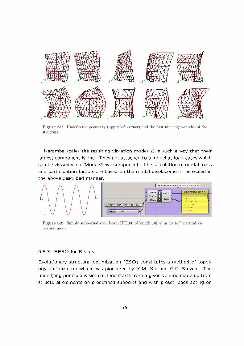
Figure 61: Undeflected geometry (upper left corner) and the first nine eigen-modes of thestructure.
Karamba scales the resulting vibration modes ~vi in such a way that their
largest component is one. They get attached to a model as load-cases which
can be viewed via a �ModelView�-component. The calculation of modal mass
and participation factors are based on the modal displacements as scaled in
the above described manner.
Figure 62: Simply supported steel beam IPE100 of length 10[m] in its 14th natural vi-bration mode.
6.5.7. BESO for Beams
Evolutionary structural optimization (ESO) constitutes a method of topol-
ogy optimization which was pioneered by Y.M. Xie and G.P. Steven. The
underlying principle is simple: One starts from a given volume made up from
structural elements on prede�ned supports and with preset loads acting on
79

it. Calculating the structural response will show that there are regions which
carry more of the external load than others. Now one removes a number
of those elements of the structure that are least strained and thus least ef-
fective. Again the response of the now thinned out model is determined,
under-utilized elements removed and so on. This iterative procedure stops
when a target volume or number of remaining structural elements is reached.
The above algorithm can be viewed as a way of tracing the internal force
�ow through a structure and removing those elements that do not form part
of it. Fig. 63 shows a cantilever after applying the �BESO for Beams�-
component on it. The algorithm works on beam and truss elements only.
For shells a separate component exists (see section 6.5.8).
Figure 63: Cantilever with initially regular mesh after application of the ”BESO forBeams”-component.
Figure 64 shows the �BESO for Beams�-component at work. On the
left side one can see the initial geometry which is a triangular mesh derived
from a surface. There exist two load cases with loads acting in the plane of
the structure in horizontal and vertical direction respectively. Three corner
80

nodes of the structure are held �xed. The right picture shows the opti-
mized structure reduced to 45% of its initial mass in the course of 20 design
iterations.
Here the description of the input parameters:
�Model� : Receives the model to be processed.
�ElemIds� : There are two alternatives concerning this input parameter:
� No input: The whole of the structure will be included in the opti-
mization procedure.
� The input consists of one string: All elements whose identi�ers
match take part.
�LCases� : List of load cases to be considered. Zero is the index of the �rst
load case. Considering the total e�ect of several load cases amounts
to adding up their individual in�uences on an element.
�TargetRatio� : Ratio of the target mass of beam- or truss elements to the
initial mass of beams/trusses in a structure. When determining the ini-
tial mass all beam- or truss- elements of the structure � irrespective of
state of activation � count. In the target structure only active elements
contribute to its mass. This enables one to apply BESO-components
in series. Depending on the activation status of the model elements
applying �BESO for Beams� will lead to an increase or decrease in the
number of active elements. The activation status of individual ele-
ments can be set by means of the �ModifyBeam�- and �ActivateModel�
components.
�MaxChangeIter� : Number of iterations within which the target mass of
the structure should be reached. If the number of iterations is selected
too low then it may occur that single beams get disconnected from the
main structure and they seem to �y. The reason for this lies in the fact
that Karamba applies a so called soft-kill approach for thinning out the
structure: elements are not removed but simply given small sti�ness
values. This ensures that structural response can be calculated under
all circumstances.
81

�MaxConvIter� : Maximum number of additional iterations for convergence
after the structures mass has reached its target value using �nChangeIter�
iterations.
�GroupIds� : Expects list of strings. Elements that match a given list entry
take part in the optimization and belong to one group. They get col-
lectively activated or deactivated during force path �nding. A structure
may consist of active and non-active elements. The initial state of a
group is determined by the state of the majority of its elements. Groups
need not be disjoint.
By clicking on the �Settings� bar you can unfold the following input-plugs:
�Factors for weighting forces/moments� : The �BESO for Beams�-component
lets you select weighting factors for the di�erent force and bending
components in an element. The weight of an element is determined
on the basis of the density of deformation energy induced by individual
cross section force components. Multiplication by the corresponding
user given weighting factor and adding up the component contributions
results in the element weight. The weight of groups results from the
average of their members. These are the available weighting factors:
� �WTension�: factor for axial tension force
� �WCompr.�: factor for axial compression force
� �WShear�: factor for resultant shear force
� �WMoment�: factor for resultant moments
�BESOFac� : Say in each iteration step there needs to be a mass of n[kg]
removed in order to meet the structures target mass in the given
nChangeIter number of iterations. With BESOFac = m there will be
(m+ 1) · n active elements moved to the pool of inactive elements. An
evaluation of the structures response follows. In a second step m · nmembers get �ipped from inactive to active so that the balance is right
again. This adds a bi-directional component to the process which often
leads to improved results.
82

�MinDist� : In some cases one wishes to limit the number of elements that
get added or removed in a certain area. �MinDist� lets you select the
minimum distance in meter [m] between the endpoints of elements that
may be changed in one iteration.
�WLimit� : At the end of the BESO-process it often occurs that a small
fraction of the elements is much less utilized than the average. �WLimit�
lets you remove those elements whose weight is below �WLimit� times
the average weight of elements.
Figure 64: Triangular mesh of beams before (a) and after (b) applying the ”BESO forBeams”-component.
On the right side of the �BESOBeam�-component these output-plugs ex-
ist:
�Max.disp� : maximum displacement of the resulting model from among all
load cases.
�Model� : structure with element activation according to the force path
found.
�Hist� : a data tree which contains for each iteration step a list of boolean
values that signify whether an element in active (true) or inactive (false).
The boolean values map directly on the model elements. Using a �Tree
Branch� component with a slider connected to a �Activate Model�-
component (see section 6.1.1) lets you inspect the history of the BESO-
process (see �g. 64).
�Is active� : renders a list of true/false values � one for each element. True
signals that the corresponding element is part of the �nal structure (i.e.
83

active). Otherwise it contains a �false� entry.
�Weights� : List of element or group weights in ascending order in the �nal
structure. This can be used as a qualitative check of the result: The
more evenly distributed the weights, the better utilized the structure.
There will always be force concentrations around supports and external
loads which show up as sharp peaks. A good way of visualization is to
use a �Quick Graph�-component (see �g. 64).
6.5.8. BESO for Shells
An in-depth description of the BESO for shells algorithm used in Karamba
can be found in [3]. Fig. 65 shows an example which starts o� from a
rectangular wall which supports two point-loads at each of its upper corners.
The result of the BESO procedure is the X-shaped structure shown on the
left side.
Figure 65: Bidirectional Evolutionary Structural Optimization (BESO) for a rectangularplate under two corner loads.
These are the main parameters that control the optimization process:
�Model� : Model to be optimized.
�ElemIds� : List of identi�ers of shells that take part in the optimization. In
case of an empty list (the default) all shells are included.
�LCases� : List of load cases to be considered. Zero is the index of the �rst
load case. Considering the total e�ect of several load cases amounts
to adding up their individual in�uences on an element.
�TargetRatio� : Ratio of the target mass to the initial mass of the shells
in a structure. When determining the initial mass all shell elements of
84
the structure � irrespective of state of activation � count. In the target
structure only active elements contribute to its mass. This enables one
to apply BESO-components in series.
�MaxIter� : Maximum number of iterations.
Under the submenu �Settings� these additional options can be used to
further customize the optimization procedure:
�ER� : Is short for evolutionary ratio and de�nes the ratio between the
volumes Vi and Vi+1 of the optimized structure in two consecutive steps:
Vi+1 = Vi · (1±ER). The sign before �ER� depends on whether elements
shall be added or removed. In case that ER < 0 � which is the default �
�ER� is set automatically: ER = (1−TargetRatio)/MaxIter+ARmax/2. In
case that �ER� is too small, the target mass of the optimized structure
can not be reached within �MaxIter� steps.
�ARmax� : The ratio between maximum number of elements to be added
per step and all shell elements.
�Nhist� : Number of iterations between the steps which are used for calcu-
lating the convergence criteria.
�Conv� : Relative change of the mass between two iterations Nhist cycles
apart below which convergence is assumed.
�Rmin� : In order to avoid the formation of checkerboard patterns a �lter
scheme is used for calculating the �tness of individual elements (see
[3], section 3.3.2). Rmin de�nes the radius of in�uence in meters for
determining the element sensitivity. It is thus important to choose this
value according to the mean element size. If Rmin < 0 (the default) then
Rmin is set equal to the characteristic element length which is calculated
as (totalArea/numberOfElements)0.5 · 2.
�Rexp� : Determines how the strain energy at nodes within the distance Rmin
of the element center is weighted for calculating an elements sensitivity.
The weight is determined as w = (Rij/∑Rij)Rexp. Here Rij = Rmin − R
with R being the distance between a sample node and the center of the
85

element.∑Rij is the sum of the center distances of all nodes closer
than Rmin to the element center.
�KillThick� : The BESO for shell procedure makes use of a so called �soft
kill� approach. Instead of removing elements from the model they are
made very soft by reducing their thickness. With the input-plug �KillTh-
ick� a value other than the default 0.00001[m] can be selected.
The output-plugs of the �BESOShell�-component return the following
data:
�Model� Model which results from the BESO optimization.
�ModelHist� List of intermediate models � one for each iteration step of the
BESO procedure.
�CHist� History of the volume weighted compliance of the structure which
drives the BESO procedure. When fed into a �Quick Graph� component
one can check whether the BESO procedure converged: at the end the
chart should be horizontal. If that is not the case try a smaller �ER�-
value.
�VHist� List of values which chart the development of the volume of the
shells to be optimized.
�Info� Returns information regarding the solution process in case something
goes wrong.
6.5.9. Tension/Compression Eliminator
The �Tension/Compression Eliminator�-component removes elements from
a model based on the sign of their axial force.
These are the available input parameters:
�Model� : model to be processed.
�MaxIter� The removal of tensile or compressive elements works in an it-
erative fashion. The procedure stops either when no changes occur
from one step to another or if the the maximum number of iterations
�MaxIter� is reached.
86

Figure 66: The ”Tension/Compression Eliminator”-component.
�BeamInds� Indexes of the elements that may be removed in the course of
the procedure. By default the whole structure is included.
�LC� You can specify a special load case to consider. The default is �0�.
�Compr� If true, then only members under compression will be kept. Oth-
erwise only members under tension will survive. This value is false by
default.
Elements selected for removal are assigned a negligible sti�ness (i.e. a
soft-kill approach is used).
6.5.10. Optimize Cross Section
Use the �Optimize Cross Section�(OptiCroSec)-component for the automatic
selection of the most appropriate cross sections of beams and shells. It takes
into account the cross sections load bearing capacity and optionally limits
the maximum de�ection of the structure.
Figure 67 shows a typical set-up. The initial structure consisted of I-
sections of type HEA100 which have a height and width of 100[mm]. They
could not sustain the given load: The resulting bending stresses would lie
way beyond the yield stress of the assumed material which is steel S235 with
fy = 23.5[kN/cm2].
First the OptiCroSec-component determines the cross section of each
element in such a way that their load-bearing capacity is su�cient for all
87

Figure 67: Cross section optimization with the OptiCroSec-component on a simply sup-ported beam.
load-cases. In order to achieve this, Karamba uses the following procedure:
1. Determination of section forces at �nSamples� points along all beams
using the initial cross section
2. For each element or given set of elements: selection of the �rst su�cient
entry from the family to which each cross section belongs
3. If no changes were necessary in step two or the maximum number of
design iterations is reached, the algorithm stops. Otherwise it returns
to step one using the cross sections selected in step two.
In statically indeterminate structures the section forces depend on the
sti�ness (i.e. cross section) of the members. This necessitates the iterative
procedure described above.
Figure 68: Cross section optimization with the OptiCroSec-component on a cantileverdiscretized with shell elements.
When performing thickness optimization on shells the list structure for
de�ning a cross section family plays a crucial role. In �g. 68 one can see
the example of a cantilever: The optimization results in thicker shells at the
top and bottom edge of the built-in side. When de�ning a list of shell cross
88

sections one needs to supply a list of lists of thicknesses and corresponding
cross section names. Each sub-list speci�es the element thicknesses of one
shell (see section 6.2.2).
For shells the mechanical utilization is calculated as the maximum Van
Mises stress in a point divided by the material strength. For cross section
optimization of shells the same procedure applies as for beams. Starting
with the �rst item of a cross section family the algorithm tests all members
and stops when a cross section is encountered for which the utilization is
less than 1.
After ensuring safety against structural failure a second, optional step fol-
lows where Karamba tries to approach a user supplied maximum de�ection.
Behind the scenes Karamba iteratively adapts temporarily the yield stress of
the materials. This may lead to uneconomic results in case of structures
where the maximum displacement occurs in a small region whereas the rest
of the structure shows a much smaller deformation. In order that the iter-
ative adaption for the maximum displacement works, the number of design
iterations should be chosen appropriately � �ve is normally su�cient.
Building codes prescribe di�erent levels of safety against reaching max-
imum displacement and load bearing limits. When using external loads at
ultimate limit state level one should keep in mind that this is approximately
1.4 times the loads used to check maximum displacement requirements.
When the given loads surpass the load bearing capacity of the biggest
cross section available in a cross section family, Karamba issues a warning
via the �Info� output-plug.
There is no guarantee, that the iteration procedure for �nding the optimal
cross sections eventually converges � so check the results via the utilization-
output of the �ModelView�-component. Due to the lower-bound theorem of
plasticity the structure will be su�cient for the given loads at any iteration
step � although some elements may show overutilization � provided that
the material is su�ciently plastic (like e.g. steel). With increasing number
of iterations the statical system tends to become more and more statically
determinate.
The pro�le selection procedure assumes that the cross sections of a family
are ordered: starting with your most favorite and descending to the least de-
sired cross section. In the cross section table �CrossSectionValues.csv� that
89

comes with Karamba all families are ranked according to their height. The
cross section with the smallest height comes �rst, the one with the largest
height last. When using cross section area as sorting criteria, structures of
minimum weight (and thus approximately cost) result. See 6.2.12 for how
to switch between minimum height and minimum weight design. Ordering
the pro�les by area may lead to structures where the cross section heights
vary signi�cantly from one beam to the next.
In order to check whether a given beam cross section is su�cient Karamba
applies a procedure for steel beams according to Eurocode 1993-1-1. The
interaction values for the cross section forces kyy, kyz and so on get calculated
according to EN 1993-1-1 appendix B. The values Cmy and Cmz are limited
to a minimum of 0.9. The design procedure takes account of normal force,
biaxial bending, torsion and shear force. For more details see section A.6. It
is possible to switch o� the in�uence of buckling for single members or set
user de�ned values for the buckling length (see section 6.1.10).
The adverse e�ect of compressive normal forces in a beam can be taken
into account globally (see section 6.5.4) or locally on the level of individual
members. The procedure applied in Karamba for cross section optimization
works on member level. A crucial precondition for this method to deliver
useful results is the determination of a realistic buckling length lb of an
element. For this the following simpli�cation � which is not always on the
safe side � is applied: Starting from the endpoints of an element, proceeding
to its neighbors, the �rst nodes are tracked that connect to more than two
elements. The buckling length is determined as the distance between these
two nodes. It lies on the safe side in case of endpoints held by the rest of the
structure against translation. When beams are elements of a larger part of a
system that buckles (e.g. a girder of a truss) then the applied determination
of buckling length produces unsafe results! One should always check this
by calculating the global buckling modes (see section 6.5.4). In case of
a free end the buckling length is doubled. Compressive normal force in
slender beams reduces their allowable maximum stress below the yield limit.
Visualizing the level of utilization with the ModelView-component will then
show values below 100% in the compressive range.
The design procedure applied in Karamba takes lateral torsional buckling
into account. An elements lateral torsional buckling length is calculated in
90

the same way as for conventional buckling. The buckling length for lat-
eral torsional buckling can be set manually via the property �BklLenLT� of
the �Modify Beam�-component. In the course of cross section optimization
Karamba checks the cross sections for local buckling and issues a warning
if necessary. The check for local buckling uses the classi�cation of cross
sections into classes 1 to 4 according to EN 1993-1-1. Class 4 cross sections
are susceptible to local buckling.
During the optimization of cross sections normal forces N II are not up-
dated. In order to include second order theory e�ects either set N II manually
or use �AnalysisThII� (see section 6.5.2) to determine N II iteratively.
The OptiCroSec-component provides the following set of input-plugs:
�Model� Model to be optimized
�ElemIds� Identi�ers of elements that should be optimized. If not speci�ed,
optimization is carried out for the entire model.
�GroupIds� List of identi�ers of groups of elements that take part in cross
section design and shall have uniform cross section. One can use the
names of element sets and regular expressions for de�ning groups..
�CroSecs� Cross section-list that contains families of cross sections ordered
from most favorite to least desired. Family membership of cross sections
is given via their �family� property.
�MaxUtil� Target value of the element utilization where �1.0� means full
utilization - the default. In some situations (e.g. early stage design)
loads or geometry can not be fully speci�ed. Then it makes sense to
keep some structural reserves for later phases by setting this value to
less than �1.0�.
�MaxDisp� For usability of a structure it is necessary to put a limit on its
maximum de�ection. This can be done using the �MaxDisp�-plug. By
default its value is �-1� which means that the maximum de�ection is not
considered for cross section design. When working with design loads
keep in mind that those are roughly a factor of 1.4 above the level to
be considered for usability.
91

In order to see all input-plugs click on the �Settings�-button to unfold the
rest of the component:
�ULSIter� Maximum number of design iterations for su�cient load bearing
capacity in the ultimate limit state (ULS). The default value is �ve.
�DispIter� Maximum number of iterations used to reach the maximum dis-
placement criteria in case there is one. The design iterations for maxi-
mum displacement come after those for load bearing capacity.
�nSamples� Number of points along beams at which their utilization is de-
termined. The default is three.
�Elast� If set to �true� (the default) cross section design is done within
the elastic range. This means that under given loads the maximum
resulting stress in a cross section has to lie below the yield stress fy
of the material. In case of materials with high ductility (like steel)
the plastic capacity of cross sections can be exploited. Depending on
the cross section shape the plastic capacity is 10% to 20% higher than
the elastic capacity. Set �Elast� to �false� in order to activate plastic
cross section design. When enabling plastic cross section design do not
be surprised that the ModelView reports utilization-levels beyond 100%.
The reason is that Karamba assumes linear elastic material behavior.
�gammeM0� Material safety factor according to EN 1993-1-1 in case that
failure is not initiated by buckling. Its default value is 1.0. In some
European countries this factor lies above 1.0
�gammeM1� Material safety factor according to EN 1993-1-1 in case that
buckling initiates failure. The default value again lies at 1.0 - may be
speci�ed di�erently in your national application document of EN 1993-
1-1.
On the output side the �Model�-plug renders the structure with optimized
cross sections. Check the �Info�-plug in order to see whether any problems
occurred during optimization. The �Mass�-plug informs you about the overall
mass of the optimized structure. �Disp�- and �Energy�-plugs return the
92

maximum displacement and internal energy of the structure after the last
cross section design iteration.
The aim of the design procedure applied in Karamba is to render plausible
cross section choices. Be aware that it builds upon assumptions like the
correct determination of buckling lengths.
6.6. Results
The results category consists of three sections. The �rst contains compo-
nents that apply to a structure in general. Components of the second and
third category apply to beams and shells respectively.
6.6.1. Deformation-Energy
In mechanics energy is equal to force times displacement parallel to its di-
rection. Think of a rubber band: If you stretch it you do work on it. This
work gets stored inside the rubber and can be transformed into other kinds
of energy. You may for example launch a small toy airplane with it: Then
the elastic energy in the rubber gets transformed into kinetic energy. When
stretching an elastic material the force to be applied at the beginning is zero
and then grows proportionally to the sti�ness and the increase of length
of the material. The mechanical work is equal to the area beneath the
curve that results from drawing the magnitude of the applied force over its
corresponding displacement. In case of linear elastic materials this gives a
rectangular triangle with the �nal displacement forming one leg and the �nal
force being its other leg. From this one can see, that for equal �nal forces the
elastic energy stored in a material decreases with decreasing displacements
which corresponds to increasing sti�ness.
Via the input �ElemIds� one can supply identi�ers of those parts for which
the deformation energy shall be calculated. An empty list means that all ele-
ments are considered. The structure of the data tree returned from the �D-
Energy�-component (see �g. 69) corresponds to Model/Load-case/Element-
result. In case of shells the list on the lowest level contains the axial or
bending energy of each element of the shell.
93

Figure 69: Simply supported beam under axial and transversal point-load: List of axialdeformation energy and bending energy for each element and load case.
6.6.2. ModelView
The ModelView-component of the �Results� subsection controls the general
display properties of the statical model (see �gure 14). More speci�c visual
properties that relate to beam and shell elements can be de�ned with the
�BeamView� and �ShellView�-component. The viewing options get stored
in the model. Settings of View-components thus stick with the model and
remain valid further down the data-stream until changed by another View-
component.
When adding a ModelView to the de�nition it is sometimes a good idea to
turn o� the preview of all other components so that they do not interfere.
Clicking on the black menu headings unfolds the ModelView and unveils
widgets for tuning the model display. Each of these will be explained further
below. The range and current value of the sliders may be set by double-
clicking on the knob.
Figure 70: Partial view of a model.
The ModelView-component features �ve plugs on its left side:
94

� �Model� expects the model to be displayed
� �LC-Factor� can be used to scale individual load cases (see further
below).
� �LC-Index� lets one select the visible load-case. The value in �LC-
Index� will be added to the load-case selected in the drop-down-list of
ModelView (��all�� counts as -1). If the resulting number is larger
than the number of available load-cases the ModelView turns red. If
the resulting value is smaller than 0 all load-cases are superimposed.
The possibility of using a number-slider for selecting load-cases makes
life easier in case that there are many of them.
� �Colors�: Color plots for e.g. stresses use a color spectrum from blue to
white to red by default. One can customize the color range by handing
over a list of RGB-values to the �Colors�-plug. There have to be at
least four colors given. The �rst color is used for values below, the last
color for values above the current number range. The remaining colors
get distributed over the number range (see �g. 71). The colors are
centered on zero if zero is part of the number range. Otherwise the
colors spread evenly between lower and upper numerical limit. In case
you want to change the coloring defaults, set them in the �karamba.ini�
�le. There it is also possible to switch o� the centering around zero by
setting �center_color_range_on_zero� to false.
� �Ids�: This plug lets one select those parts of a model which shall be
displayed. It expects a list of strings. The default value is an empty
string which means that all of the model shall be visible. As one can
see in �g. 70 it is possible to input regular expressions. These must
start with the character �&� and adhere to the conventions for regular
expressions as used in C#. The identi�er of each element of the model
is compared to each item of the given string list. In case a list entry
matches the element identi�er the element will be displayed. Fig. 70
contains four examples of �Id� lists: The �rst would limit visibility to
element �A�, the second to element �B�. The third is a regular expression
which matches elements �A� or �C�. The fourth matches elements �A�
to �C�.
95

Figure 71: Color plot of strains with custom color range.
There are �ve output plugs on the ModelView-component:
� �Model� is the model which was fed in on the left side.
� From the �defMesh� output-plug you can get the mesh of the shells and
beam cross sections of the deformed model for further processing. It is
a list of meshes with each item corresponding to one shell or beam.
� The �defAxes� plug delivers the axes of the beams of the deformed
structure as interpolated 3rd degree nurb-splines. Use the Length/Sub-
division slider to set the number of interpolation points.
� �defModel�: When there are results available from a statical calculation
de�ections are scaled and added to the node coordinates of the original
model so that it contains the deformed geometry.
The �Display Scales�-submenu
The �Display Scales�-submenu contains check boxes and sliders to enable/dis-
able and scale displacements, reaction forces at supports, load-symbols,
support-symbols, local coordinate systems and symbols for joints at the
endpoints of elements. The displacement scale in�uences the display and
the output at the model-plug. It has no e�ect on stresses, strains, etc.. The
colors of the local coordinate axes red, green, blue symbolize the local X-,
Y-, and Z-axis.
96

Figure 72: Local axes of cantilever composed of two beam elements, reaction force andmoment at support.
The �Render Settings�-submenu
The slider entitled �Length/Segment[m]� lets one control the distance at
which beam results (displacements, forces, moments, etc.) are plotted (see
6.6.8). It also sets the number of control points that are used for the
�defAxes�-output and for displaying.
In some cases the color display of results gets distorted by the presence of
stress concentrations or utilization peeks. They make much of the structure
look unstrained with some small patches of color where the peeks are. The
�Upper Result Threshold�- and �Lower Result Threshold�-sliders let you elim-
inate these extreme values. In case of the �Upper Result Threshold�-slider
a value of x% sets the upper boundary value of the color range in such a
way that x% of the actual value range is below. For the lower threshold it is
vice versa. Values in the model beyond the given thresholds are given special
colors to make them easily recognizable.
By default the result threshold values given above refer to the value range
in percent. Sometimes it turns out to be practical to prescribe absolute
97

values as thresholds (e.g. the yield stress of a material). The radio button
group �Result Threshold as� can be used to switch between relative and
absolute thresholds.
Limiting the value range of utilization values can be confusing: If the
result thresholds are given in percent, then setting the lower threshold to
zero and the upper to 100 displays the full range of utilization values. If the
result thresholds are given as absolute values then a lower threshold of −100
and an upper threshold of 100 limit the color range to the areas where the
material resistance is su�cient.
The �Structure Tags�-submenu
The �Structure Tags� menu contains checkboxes for adding visual informa-
tion to parts of the model:
� �Node tags� attaches node-indexes to each node.
� �Element tags� attaches element-indexes to each element.
� �Element Ids� displays the element identi�ers.
� �Elements�: If enabled the �defAxes� output-plug emits the axis of the
deformed elements as lines and shows them on the Rhino-canvas.
� �CroSec names� displays the name of the cross-section of each element
� �Material names� displays the name of the material of each element
� �Eccentricities� visualizes beam eccentricities as blue lines at the end-
points if active.
� �Load values� adds the numerical values of loads or point masses to the
corresponding sysmbols.
� �NII� prints the value of second order theory normal forces N II for all
element where it is not equal to zero. For the meaning of N II see 6.5.2.
The �Load-case Selection�-submenu
The �Load-case Selection� menu contains a drop-down list from which one
can choose the load-case which should be displayed. By default it is set to
98

��all�� which means that the results of all load-cases are superimposed.
De�ne load-factors by feeding a corresponding list of numbers into the �LC-
Factor� input-plug.
The �Load-case Selection� sets the load-case to be queried for the shell
results-components placed further downstream (e.g. �Force Flow Lines on
Shells�, �Principal Stress Lines on Shells�,...).
6.6.3. Nodal Displacements
Figure 73: Simply supported beam under axial and transverse point-load: List of nodaldisplacements: vectors with translations and rotations for each node and load case.
The �NodeDisp� component lists the displacements of each node for all
load cases. Two data-trees consisting of vectors make up its output. The
two rightmost dimensions correspond to Model/LoadCase. The data for
each node at the output plugs �Trans� and �Rot� consists of a vector which
contains the three translations or three rotations (see �g. 73). The vectors
refer to the global coordinate system. Their units are meter and radiant
respectively. A positive rotation say about the global X-axis means that the
node rotates counter clockwise for someone who looks at the origin of the
coordinate system with the X-axis pointing towards him or her.
99

Figure 74: Approximation of principal strains in a simply supported slab simulated withbeam elements under a point-load. Irregularity of principal strain directions is due to theirregularity of the element grid.
6.6.4. Principal Strains Approximation
Karamba includes shell elements from which principal stress lines can be
retrieved (see sec. 6.6.11). In case of single layer grid shells made up
of beams the �Approximate Principal Strains�-component can be used to
determine the approximate principal strain directions of such structures (see
�g. 74). It works on arbitrary sets of deformed points.
The calculation of principal strains is based on the assumption of a con-
tinua. When applied to nodes connected with linear elements the result can
thus only result in a qualitative picture � therefore the term �Approximate�.
The �Approximate Principal Strains�-component expects as input a refer-
ence model (input-plug �Model�) and the same model in a deformed con�g-
uration (input-plug �def.Model�). The deformed model can be the output
of a ModelView-component. Hand over a list of points to the input-plug
'Point' where principal strain directions shall be computed. For each point
in this list the following two steps are applied: First those three nodes of
the reference model that do not lie on a line and have minimum distance
to the given point are determined. Second the strains in the sides of the
thus found triangle determine the principal strain directions � plane stress is
assumed. The conversion of �rst (output-plug �VT1�) and second principal
strains (output-plug �VT2�) to vectors occurs in such a way that they align
with the average displacement of the triangle that de�nes the corresponding
strain-state. The size of the vectors emanating from �VT1� and �VT2� can
100

be scaled by providing a factor in the input-plug �Scale�.
The principal strains are tangents to the principal stress lines of a struc-
ture. Use e.g. Daniel Hambleton's �SPM Vector Components� (see http:
//www.grasshopper3d.com/group/spmvectorcomponents) to retrieve these lines
from the strain-vector-�eld.
6.6.5. Reaction Forces
Figure 75: Beam under axial and transverse point-load: Reaction forces and moments forboth load cases.
The �Reaction Forces�-component gives access to the reaction forces and
moments at supports. It expects a model at its input-plug and returns via
�RF� and �RM� a tree containing reaction forces in [kN ] and reaction mo-
ments in [kNm] as three dimensional vectors. The two rightmost dimensions
correspond to LoadCase/Support. The support reactions are ordered in such
a way that the indexes of the nodes they attach to form an ascending se-
quence. In case of locally oriented supports, reaction forces refer to the local
coordinate system. �Pos� returns the position of the supports in the same
order as the results. �SumRF� and �SumRM� o�er the possibility to check
the resultant reaction moments and forces of each load-case.
6.6.6. Utilization of Elements
Use the �Utilization of Elements�-component in order to get the level of
utilization for each element. It comes as a multi-component where the drop-
down list on the bottom decides whether the utilization of shell of beam
101

Figure 76: Beam under axial and transverse point-load: Utilization of the cross sectionsof the elements.
elements shall be returned.
The input-plug �Model� expects an analyzed model. With �ElemIds� it
is possible to limit the range of elements which shall be considered. By
default the component returns results for all elements. The �LCase� selects
the load-case to be used for calculating the utilization. By default it is set
to �-1� which means that the maximum utilization of all load-cases will be
returned.
Utilization of Beams
Fig. 76 shows the utilization component for beams. The meaning of the
input-plugs �nSamples�, �Elast�, �gammaM0� and �gammaM1� exactly corre-
sponds to that of the �Optimize Cross Section� (see 6.5.10). The algorithm
for determining an elements utilization corresponds is the same as that under-
lying the cross section optimization procedure. Set the input-plug �Details?�
to �true� in order to get intermediate values of the utilization calculation at
the output-plug �Details�. For large structures the generation of the detailed
output may take some time.
Utilization numbers for beams rendered by this component (output-plug
�Util�) and the ModelView show di�erences - especially for compressive axial
forces: The ModelView-component returns the ratio of stress to yield stress
as level of utilization, whereas the �Utilization of Elements�-component also
includes buckling. See for example the two utilization entries on the in �g.
76: The second load case (i.e. number �1�) is made up of an axial load
102

acting in the middle of the beam. As both ends are axially �xed, one beam
is in tension, on in compression. The absolute value of the normal force in
both elements is the same. Yet the beam under compression has a utilization
of 0.26, the one under tension only 0.05. �1� means 100%.
The output-plugs �sig-max� and �sig-min� return the minimum and maxi-
mum stress in each beam.
In order to diagnose the reason why a speci�c beam shows over-utilization
the output-plugs �Util-N�, �Util-Vy�, �Util-Vz�, �Util-Mt�, �Util-My� and �Util-
Mz� return the contribution of each cross section component to the overall
utilization. When enabled via �Details?� the output-plug �Details� renders
a detailed account of intermediate values used for the calculation of the
element's utilization according to EN 1993-1-1.
Utilization of Shells
Figure 77: Utilization of a shell consisting of two elements.
The utilization calculated for shells (see �g. 77) is the ratio between yield
stress and Van Mises Stress in each element of the shell. The output-plug
�Util� lists the utilization of each element of the shell in the same order as
the mesh-faces are listed in the mesh which underlies the shell geometry.
6.6.7. Beam Displacements
In case you want to know how displacements change over the length of
a beam use the �Beam Displacements�-component (see �g. 78). The
� 'LCase�, 'maxL� and � 'NRes� input-plugs work analogously to those of
the �Section Forces�-component (see section 6.6.10).
103

Figure 78: Beam consisting of two elements under axial and transverse point-load: Listof displacements along the axis: three components of translations and rotations for eachsection and load case.
Figure 79: Display of utilization and bending moments of cantilever beam.
104

6.6.8. BeamView
The �BeamView� components controls the display options related to beams
(see �g. 79). This concerns the rendering of cross section forces, resultant
displacements, utilization of material and axial stress.
The �Render Settings�-submenu
When activated, �Cross section�, �Displacement�, �Utilization� and �Axial
Stress� result in a rendered view of the model. Utilization is calculated as
the ratio between the normal stress at a point and the yield stress of the
corresponding material. Shear and buckling are not considered.
(a) (b)
Figure 80: Rendered images of the beam. Left: ”Cross section”-option enabled. Right:”Axial Stress” enabled.
The color range of the results starts at the minimum value and stretches to
the maximum. You can de�ne individual color ranges for all result quantities
in the �karamba.ini�-�le. A �Legend�-component lets you inspect the meaning
of the colors.
The mesh of the rendered image is available at the �Mesh�-output of the
�BeamView�-component. Two sliders control the mesh-size of the rendered
beams: First �Length/Segment� of �ModelView� determines the size of sec-
tions along the middle axis of the beams. Second �Faces/Cross section�
of �BeamView� controls the number of faces per cross-section. For ren-
dering circular hollow cross sections the number of �Faces/Cross section� is
multiplied by six in order to get a smooth visual result.
It is instructive to see which parts of a beam are under tension or com-
pression. Activate the �Stress�-checkbox in menu �Render Settings� in order
to display the stresses in longitudinal beam direction. Red (like brick) means
compression, blue (like steel) tension. In some models there may exist small
regions with high stresses with the rest of the structure having comparatively
105

Figure 81: Mesh of beams under dead weight with Render Color Margin set to 5%.
low stress levels. This results in a stress rendering that is predominantly
white and not very informative. With the sliders for �Result Threshold� of
the �ModelView� you can set the percentage of maximum tensile and com-
pressive stress at which the color-scale starts. Compressive stress values
beyond that level appear yellow, excessive tensile strains green (see �gure
81).
Display of cross section forces and moments
The �Section Forces� sub-menu lets you plot section forces and moments as
curves, meshes and with or without values attached. All generated curves
and meshes get appended to the BeamViews curve and Mesh output. The
graphical representation is oriented according to the local coordinate axes
of the beam and takes the unde�ected geometry as its base. The index of
bending moments indicates the local axis about which they rotate, for shear
forces it is the direction in which they act (see also �g. 83). Customize
the mesh-colors via �karamba.ini�. The slider �Length/Subdivision� in sub-
menu �Render Settings� of the ModelView-component controls the number
of interpolation points.
106

Figure 82: Moment My (green) about the local beam Y-Axis and shear force Vz (blue) inlocal Z-direction.
6.6.9. Resultant Section Forces
The �Beam Resultant Forces�-component retrieves axial forces N, resultant
bending moments M and shear forces V for all beams and load cases. See
�g. 83 for the de�nition of N, V and M. The sequence of element results
corresponds to the sequence of beams. Thus the data can be used for cross
section design of radially symmetric elements.
Figure 84 shows a beam with two load cases presented in one picture.
The beam consists of two elements and has a total length of eight meters.
In load case zero a vertical force of magnitude 1kN acts vertically downwards
in the middle of the beam. Load case one consists of a point-load of 3kN
directed parallel to the undeformed beam axis. The results at the output-
plugs �N� and �M� in �g. 84 are trees that hold the beams normal force in
kilo Newton [kN] and resultant bending moment in kilo Newton times meter
[kNm] respectively. There is only one model fed into the S-Force component
107

Figure 83: Normal force N, shear force V and resultant moment M at a cross sectionwith local coordinate axes XYZ. Force and bending moment components are positive in thedirection of the local coordinate axes.
thus the second index from the right is zero. The �rst index from the right
refers to the load case. If the input-plug �LCase� has a value other than the
default of �-1� the output in �N�, �M�, and �V� is limited to the load-case
with the corresponding index. With �BeamIds� the result output may be
con�ned to a subset of the beams in the model.
Tensile normal forces come out positive, compressive normal forces have
negative sign. The resultant moment yields always positive values as it is
the length of the resultant moment vector in the plane of the cross section.
Figure 84: Beam under axial and transverse point-load: List of normal forces, shearforces and moments for all elements and all load cases.
108

The input-plug �NRes� sets the number of equidistant points along the
beam axis where resultant forces are calculated in order to determine the
maximum values for output. In case of zero gravity and in the absence of
uniform beam loads the maximum values of M and N occur at the endpoints.
Otherwise these maxima may lie inside the elements. The default value of
�NRes� is three which means that values are checked at the beams end-points
and in the middle.
As M is always rendered positive the maximum along an element is un-
ambiguously given. Under gravity normal forces in a beam may change sign.
In such a case Karamba returns that N which gives the maximum absolute
value.
Fig. 84 shows the results of a simply supported beam consisting of two
elements under two load-cases: In load case zero both elements return zero
normal force because there acts no external axial load. The maximum mo-
ment of both elements is 2[kNm]. For a simply supported beam under a
mid-point transverse load the maximum moment occurs in the middle and
turns out to be M = F · L/4 = 1[kN ] · 8[m]/4 = 2[kNm].
The axial force of 3[kN ] in load case one �ows to equal parts into both
axial supports. It causes tension (1.5[kN ]) in the left element and compression
(−1.5[kN ]) in the right one.
6.6.10. Beam Forces
Sometimes it is desirable to have section forces and moments represented as
components in the direction of the local axes of the cross section instead of
resultant values. Use the �Beam Forces�-component in such a case. Its out-
put is similarly structured as that of the �Beam Resultant Forces�-component
described above, but its output plugs comprise the force components in local
directions (see �g. 85). The input parameters �maxL� and �NRes� determine
the number of results along the beam axis. �maxL� can be used to control
the maximum distance between results. A negative value for �maxL� means
that there is no maximum distance condition. �NRes� sets the number of
results along the beams. The beams endpoints are automatically included
in the output.
�LCase� and �BeamIds� input can be used to limit the results to a speci�c
109

load-case of a subset of the beams in the model.
Figure 85: Simply supported beam under axial and transverse point-load: List of normalforces, shear forces and moments for all elements and all load cases along an the elements.
6.6.11. Line Results on Shells
�Line Results on Shells� is a multi-component which can be used to generate
force-�ow-lines, iso-lines, principal moment- and stress-lines.
Force Flow Lines on Shells
Figure 86: Cantilever consisting of triangular shell elements: Flow lines of force in hori-zontal direction.
Force �ow (FF) lines or load pathes (as they are also sometimes called)
illustrate the load distribution in structures [5]). There is a loose analogy
between those force �ow (FF) lines and streamlines in hydromechanics: The
law of conservation of mass in hydromechanics is matched by the static
conditions of equilibrium in a speci�ed direction. If there are two FF-lines
the resultant force between those in a prede�ned direction stays constant.
110
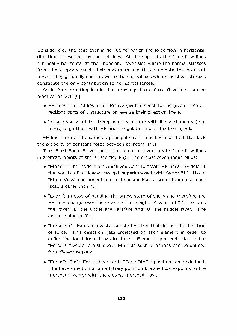
Consider e.g. the cantilever in �g. 86 for which the force �ow in horizontal
direction is described by the red lines. At the supports the force �ow lines
run nearly horizontal at the upper and lower side where the normal stresses
from the supports reach their maximum and thus dominate the resultant
force. They gradually curve down to the neutral axis where the shear stresses
constitute the only contribution to horizontal forces.
Aside from resulting in nice line drawings those force �ow lines can be
practical as well [5]:
� FF-lines form eddies in ine�ective (with respect to the given force di-
rection) parts of a structure or reverse their direction there.
� In case you want to strengthen a structure with linear elements (e.g.
�bres) align them with FF-lines to get the most e�ective layout.
FF-lines are not the same as principal stress lines because the latter lack
the property of constant force between adjacent lines.
The �Shell Force Flow Lines�-component lets you create force �ow lines
in arbitrary points of shells (see �g. 86). There exist seven input plugs:
� �Model�: The model from which you want to create FF-lines. By default
the results of all load-cases get superimposed with factor �1�. Use a
�ModelView�-component to select speci�c load-cases or to impose load-
factors other than �1�.
� �Layer�: In case of bending the stress state of shells and therefore the
FF-lines change over the cross section height. A value of �-1� denotes
the lower �1� the upper shell surface and �0� the middle layer. The
default value in �0�.
� �ForceDirs�: Expects a vector or list of vectors that de�nes the direction
of force. This direction gets projected on each element in order to
de�ne the local force �ow directions. Elements perpendicular to the
�ForceDir�-vector are skipped. Multiple such directions can be de�ned
for di�erent regions.
� �ForceDirPos�: For each vector in �ForceDirs� a position can be de�ned.
The force direction at an arbitrary point on the shell corresponds to the
�ForceDir�-vector with the closest �ForceDirPos�.
111

� �Source�: De�nes points on the shell where FF-lines shall originate. You
can feed points on or near the shell into this plug. It is also possible to
use lines that intersect the shell. In case of multiple intersections there
will be the same number of FF-lines.
� �Seg-L�: Intended length of the segments of the resulting FF-lines. Is
0.5[m] by default. A negative value means that only INT (abs(Seg − L))
line segments will be drawn.
� �dA�: This parameter sets the accuracy with which the FF-lines get
determined: It is the maximum di�erential angle between to adjacent
pieces of a FF-line. If this criteria results in pieces of length smaller
than �Seg-L� then they will be joined before sent to the output-plug
�Line�. By default this value is set to 5[deg].
� �theta�: Here you can de�ne an angle between the FF-lines and those
lines output at the �Line�-output plug. The angle is in [deg] and defaults
to zero.
The output of the �ShellFFlow�-component consists of lines arranged in
a data tree. The right-most dimension contains the branches of each �ow-
path: In case of a e.g. a plane there are two branches that originate from
the given intersection point. In case of T-like shell topologies this number
can grow to three and larger.
The load-case considered is that de�ned in the nearest upstream �ModelView�-
component.
Isolines on Shells
The �Isolines on Shells�-component lets you do two thing. First draw con-
tour lines on shells that connect points of equal principal stresses, principal
moments, utilization, resultant displacements or shell thickness (see �g. 87).
Second query results in arbitrary points of the shell.
The input-plugs �Model�, �Layer� and �Seg-L� have the same meaning
as for the �Force Flow Lines on Shells�-component (see sec. 6.6.11). In
terms of placing iso-lines on the structure the input �Vals|Pts|Lines� o�ers
the following options:
112
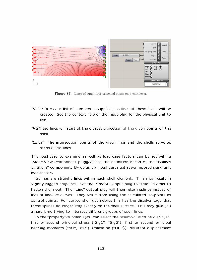
Figure 87: Lines of equal first principal stress on a cantilever.
�Vals�: In case a list of numbers is supplied, iso-lines at these levels will be
created. See the context help of the input-plug for the physical unit to
use.
�Pts�: Iso-lines will start at the closest projection of the given points on the
shell.
�Lines�: The intersection points of the given lines and the shells serve as
seeds of iso-lines
The load-case to examine as well as load-case factors can be set with a
�ModelView�-component plugged into the de�nition ahead of the �Isolines
on Shells�-component. By default all load-cases get superimposed using unit
load-factors.
Isolines are straight lines within each shell element. This may result in
slightly rugged poly-lines. Set the �Smooth�-input plug to �true� in order to
�atten them out. The �Line�-output-plug will then return splines instead of
lists of line-like curves. They result from using the calculated iso-points as
control-points. For curved shell geometries this has the disadvantage that
those splines no longer stay exactly on the shell surface. This may give you
a hard time trying to intersect di�erent groups of such lines.
In the �property�-submenu you can select the result-value to be displayed:
�rst or second principal stress (�Sig1�, �Sig2�), �rst or second principal
bending moments (�m1�, �m2�), utilization (�Util�)), resultant displacement
113

(�Disp�) or shell thickness (�Thick�).
The �Lines�-output data-structure corresponds to that of the �Force Flow
Lines on Shells�-component. Each number in the output-plug �Value� cor-
responds to one piece of isoline from the �Lines'-output.
Principal Moment Lines on Shells
Works like the �Principal Stress Lines on Shells� component (see section
6.6.11). Instead of principal stress lines it returns principal moment lines.
Principal Stress Lines on Shells
Figure 88: Principal stress lines: they are tangent to the first and second principal stressdirection. The coloring reflects the level of material utilization.
Principal stress (PS) lines are tangent to the principal stress directions (see
�g. 88). In the case of a cantilever they either run parallel or at right angle
to the free boundaries. In the middle where normal stresses due to bending
vanish �rst and second principal stress lines intersect at 90[deg].
The meaning of the input-plugs of the �Principal Stress Lines on Shells�-
component correspond to that of the �Force Flow Lines on Shells�-component
(see sec. 6.6.11 for details). On the output side �Lines1� and �Lines2� hold
the �rst and second principal stress lines in data trees: the right-most di-
mension holds a list of lines that represent a part of a PS-line. There are
usually two parts per line that start o� to either side of the starting point.
In case of more complicated topologies there can be more than two parts.
These parts populate the second dimension from the right.
114

Figure 89: Cantilever analyzed as shell structure: directions of second principal normalforces at element centers.
6.6.12. Principal Force Directions on Shells
The �Principal Force Directions on Shells�-component lets you retrieve prin-
cipal normal forces and moments at element centers (see �g. 89). All shells
of a model get considered by default. Use the input-plug �ElemIds� to select
a subset. Results refer to the selected load-case at the nearest upstream
�ModelView�-component.
The order of all result lists corresponds to the order of faces in the mesh
used to generate the shell. Output-plug �P� lists the coordinates of the
element centers where the normal forces and bending moments were cal-
culated. �N1� and �N2� deliver the �rst and second principal normal force
directions as vectors. Their length corresponds to the absolute value of the
corresponding quantity in [kN/m]. The output plugs �M1� and �M2� return
�rst and second principal bending moment directions.
6.6.13. Principal Stress Directions on Shells
This components provides the same results as the �Princ. Stress 1-2� option
of the �ShellView�-component (see �g. 90). The output-plug �P� renders
the positions of the elements centroids. �V1� and �V2� return corresponding
vectors for the �rst and second principal stresses there. Thin out results
by setting �Result Threshold� of ModelView (needs to be upstream of the
data-�ow) to a value of less than 100% . Like for isoline and force-�ow
lines a speci�c load case or superimposition of load cases can be set via
115

Figure 90: Triangular mesh of shell elements and principal stress directions at their cen-troids. Colors indicate the resultant displacement.
ModelView. By default all load-case results get added up using unit load
factors.
6.6.14. Shell Forces
Sometimes it is of interest to know not only the directions (see section
6.6.12) but also the value of principal normal forces and moments on shells.
In such cases the �Shell Forces�-component comes in handy. It lists the
results in the same order as the �Principal Force Directions on Shells�-
component. Thus the element centers returned there can be used in com-
bination with the numeric results.
Distributed normal forces are negative in case of compression. Positive
bending moments result in tension on the upper side of a shell. The upper
side of a shell element is de�ned by a positive value of the local Z-axis. When
in doubt about the orientation of your shell elements enable the preview of
local element axes in the �ModelView�-component (see section 6.6.2).
6.6.15. ShellView
The �ShellView�-component works like the �BeamView�-component (see sec.
6.6.8 and controls the display of shell results. Figure 91 shows the resultant
displacement of a shell.
You can choose from these rendering options:
116

Figure 91: Resultant displacement of a shell.
� �Cross section�: shows the upper and lower shell surface and adds them
to the output at the �Mesh�-output plug.
� �Displacement�: colors the shell according to the resultant displacement.
� �Utilization�: renders the material utilization of shells. The utilization is
calculated as the ratio between yield stress of the material and maximum
Van Mises Stress along the shells cross section hight. The Van Mises
Yield criterion is not applicable to brittle materials like concrete.
� �Princ. Stress 1�: visualizes the resultant value of the �rst principal
stress in the plane of the shell.
� �Princ. Stress 2�: displays the resultant value of the second principal
stress. direction would also be a correct result.
� �Van Mises Stress�: renders the Van Mises Stress.
� �Layer of Results�: sets the shell layer on which results are calculated.
A value of +1 corresponds to the upper surface, −1 to the lower.
� �Princ. Stress 1-2�: Enables/disables and scales the vector display of
principal stresses in the element centers. Use the �Result Threshold�
sliders in the �Display Scales�-menu of the �ModelView�-component to
thin them out if necessary.
117

6.7. Export
Karamba is not meant to be a substitute for a full blown structural engi-
neering �nite element software package. Instead it aims at providing �ex-
ibility in testing di�erent structural designs that the more traditional FE-
applications lack. We therefore started to implement interfaces to those
traditional civil engineering packages. At the moment Karamba supports
data exchange with RStab5, RStab6, RStab7 and Robot. With Geome-
tryGym (see https://geometrygym.wordpress.com/downloads/ it is possible to
export Karamba model data to IFC.
6.7.1. Export Model to DStV
Communication between Karamba and RStab or Robot works via �DAStV�-
�le which is a �STEP�-derivative.
In order to create an exchange �le place a �Export Model to DStV�-
component on you de�nition and feed it with a model via the �Model�-plug.
The �Path�-plug lets you chose a name for the exchange-�le. RStab names
cross sections and materials depend on the selected language. Therefore set
RStab to �English� before importing Karamba DAStV-�les.
The output-plug �DAStV� returns the export-�le as a list of strings which
can be viewed with a �Panel�-component. Check the output of the �Info�-
plug to see whether Karamba encountered problems during export.
The di�erent versions of RStab interpret some aspects of DAStV data
di�erently. For example distributed, projected loads will not be imported
correctly in all versions of RStab. Therefore you should always compare
the structural response calculated with the exported model in RStab to that
obtained with Karamba.
6.8. Utilities
6.8.1. Mesh Breps
Mesh Breps1: In Karamba the geometry of shells is represented by meshes.
Each mesh face corresponds to a constant strain �nite element. The element
1The �Mesh Breps� component was programmed by Moritz Heimrath.
118

Figure 92: Unified mesh generated from Breps using the ”MeshBreps”-component; cre-ated by Moritz Heimrath.
nodes determine its connectivity to the other parts of the structure. Thus
point-loads, supports, point-masses and the like can only be attached to
mesh vertices. When two meshes have common boundaries they need to
have identical vertices there in order to be structurally connected.
The �MeshBreps�-component ensures the connectedness of meshes gen-
erated from multiple breps. It also allows to de�ne points on those breps
where mesh vertices shall result. Fig. 92 shows the uni�ed mesh based on
four breps and one prede�ned point.
These input-plugs control mesh generation (see �g. 93):
� �Brep�: List of breps to be joined and meshed.
� �IPts�: Points on breps or at their boundaries where mesh vertices shall
be generated.
� �MRes�: Target size of mesh faces in meter.
� �Edge Re�nement Factor�: Multiplication factor for �MRes� that deter-
mines the target edge length of faces at brep-boundaries.
119

Figure 93: In- and output of the ”MeshBreps”-component; created by Moritz Heimrath.
� �Point Reduction�: If �True� vertices in overly dense areas get culled.
Such regions may result from a distorted UV-space in the underlying
brep. Points closer than half of �MRes� to their next neighbor get
removed.
� �SStep� and �SIter�: These two parameters let you control mesh relax-
ation. Triangular �nite shell elements give better results when having
sides of approximately equal length. The smoothing algorithm tries
to improve the mesh in that direction: It moves each vertex towards
the center of gravity of those vertices it connects to. During mesh
relaxation vertices always remain on the brep they belong to.
The output of the �MeshBreps�-component consists of meshes with iden-
tical vertices at common boundaries. The �Info� output-plug provides infor-
mation regarding the meshing process.
6.8.2. Nearest Neighbors
Assume you have two lists of points: say �FromPts� and �ToPts�. Further
imagine you want to have a network that connects each point of the �rst set
with a prede�ned number of its nearest neighbors in the second set (or to
points in set two that lie within a given distance). In that case the �Nearest
Neighbor�-component will be the right choice. It outputs lists of connection
lines and a corresponding connectivity diagram. Be aware of the fact that
120

these lists will probably contain duplicate lines. But this is no big problem
(see section 6.8.4).
6.8.3. Multi-dimensional Nearest Neighbors
Figure 94: Random points in a unit volume connected to their nearest neighbor in a 5-Dsetting
A nearest neighbor search can be generalized to any number of dimensions.
Use the �Multi-dimensional Nearest Neighbors�-component in case of more
than three. Fig. 94 shows an example with �ve dimensions: Dimensions one
to three represent space. Dimension four is the shortest distance between
each point and the thick red guide line. The curve parameter of the guide
line at the point where it meets the line of shortest distance acts as �fth
dimension. Each of the randomly generated points is connected with its
nearest neighbor. One can see from �g. 94 that the resulting line segments
align to the guide curve � in some way.
There are three input-plugs on the component:
� �FromPts�: expects a list of lists, where the rightmost list comprises
n values which are the coordinates of the point. The 'FromPts�-input
121

speci�es points where nearest neighbor connections can start.
� �ToPts�: expects the same sort of input as �FromPts�. It contains the
points where nearest neighbor connections can end.
� �NN�: number of nearest neighbor connections to be generated for each
point in �FromPts�
The output �C� of the �Multi-dimensional Nearest Neighbors�-component
is a connectivity diagram.
6.8.4. Remove Duplicate Lines
When you have a list of lines that you suspect of containing duplicate lines
then send it through this component and out comes a puri�ed list of ones of
a kind. The input-plug �LDist� determines the limit distance for nodes to be
considered as identical. Lines of length less than �LDist� will be discarded.
Lines that overlap only partly can not be detected.
6.8.5. Remove Duplicate Points
Does essentially the same as the component described above � only with
points instead of lines.
6.8.6. Get Cells from Lines
This component takes a connectivity diagram and corresponding nodes and
determines all closed cells. Input plug �Pl� can be used to supply planes that
are approximately parallel to the cells. The result is a connectivity diagram
of the closed cells.
6.8.7. Line-Line Intersection
This component takes a list of lines as input and mutually tests them for
intersection. Output-plug �IP� delivers a list of intersection points. �LSS�
returns all the line-segments including those which result from mutual inter-
section. The input-plug �LTol� sets the tolerance length in meter for �nding
122

intersections between lines that do not actually intersect. �LTol� is also the
minimum length of segments at the ends of lines (e.g. at T-intersections).
6.8.8. Element Felting
Figure 95: The elements ”A” and ”B” of the original model are connected resulting inthe additional element ”C”.
Sometimes one has several (potentially) structural elements neatly posi-
tioned in space but no connections between them. The �Element Felting�-
component helps out in such situations by generating connections between
neighboring elements (see �g. 95). The components behavior can be con-
trolled with these input-plugs:
� �Model�: Karamba model to be dealt with
� �LimDist� [m]: The �Element Felting�-component calculates the short-
est distance between each pair of elements in the model. If this distance
is less than �LimDist� a connection will be generated.
� �SnapLen� [m]: In case that a connection is to be generated the par-
ticipating elements need to be divided and a connection element intro-
duced. If any of the thus arising elements has a length of less than
�SnapLen� then the element will be removed and its endpoints snap to
the older point of the two.
� �MaxELen� [m]: you can set here a length limit for elements that shall
take part in the felting-process. All element longer than the value of
�MaxELen� will be ignored.
123
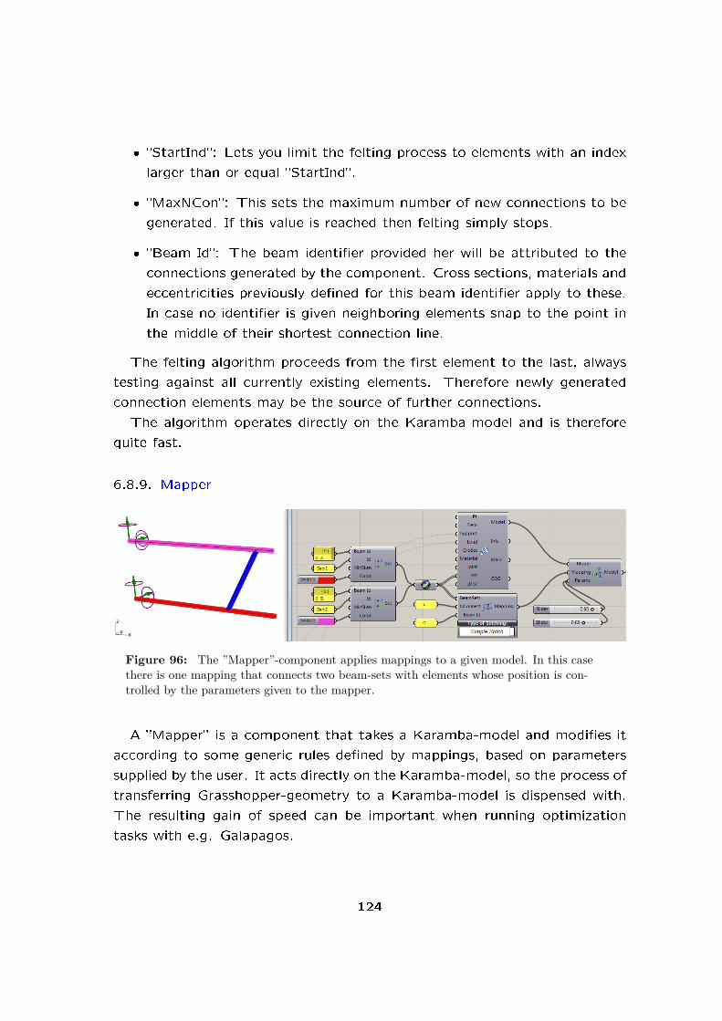
� �StartInd�: Lets you limit the felting process to elements with an index
larger than or equal �StartInd�.
� �MaxNCon�: This sets the maximum number of new connections to be
generated. If this value is reached then felting simply stops.
� �Beam Id�: The beam identi�er provided her will be attributed to the
connections generated by the component. Cross sections, materials and
eccentricities previously de�ned for this beam identi�er apply to these.
In case no identi�er is given neighboring elements snap to the point in
the middle of their shortest connection line.
The felting algorithm proceeds from the �rst element to the last, always
testing against all currently existing elements. Therefore newly generated
connection elements may be the source of further connections.
The algorithm operates directly on the Karamba-model and is therefore
quite fast.
6.8.9. Mapper
Figure 96: The ”Mapper”-component applies mappings to a given model. In this casethere is one mapping that connects two beam-sets with elements whose position is con-trolled by the parameters given to the mapper.
A �Mapper� is a component that takes a Karamba-model and modi�es it
according to some generic rules de�ned by mappings, based on parameters
supplied by the user. It acts directly on the Karamba-model, so the process of
transferring Grasshopper-geometry to a Karamba-model is dispensed with.
The resulting gain of speed can be important when running optimization
tasks with e.g. Galapagos.
124

Fig. 96 shows a de�nition where a mapper applies a mapping called �Sim-
ple Stitch� on a given model which originally consists of two elements: �A�
and �B�. The input-plug �Params� receives two parameters. In the context of
the �Simple Stitch�-mapping these parameters give the relative position on
the two beam-sets �A� and �B� where a connection �C� shall be introduced.
So a mapping encapsulates an operation and the mapper activates it 10.
Currently Karamba o�ers mappings which mainly deal with connecting
existing beam-sets by variants of an operation termed �stitching�. The notion
comes from the analogy to joining together pieces of cloth. These mappings
will be explained further below. They are rooted in the research project
�Algorithmic Generation of Complex Space Frames� which was conducted at
the University of Applied Arts Vienna.
6.8.10. Interpolate Shape
The �Interpolate Shape�-component allows one to span a design-space with
basic means: one Karamba-model acts as origin of that space; an arbitrary
number of other models de�ne a coordinate axis each. Linear interpolation
takes place between the model at the origin and those de�ning the axes. A
parameter value of 0.0 corresponds to the origin, 1.0 to the model de�ning
the corresponding axis.
Figure 97: Definition for optimizing the shape of a simply supported beam under mid-span single load.
Fig. 97 shows a de�nition where the �rst 30 eigen-forms (the thin red
lines in 98) of a simply supported beam serve as the shape-dimensions of
10In other words: a mapping is a functor.
125

the design space.
Galapagos is used to determine the position in that design-space which
results in minimum de�ection under a single load at mid-span. It is clear
(think of a hanging model) that the optimum shape has a sharp kink under
the load and is otherwise straight.
Fig. 98 shows the result of the optimization run which resembles the
ideal shape to a large degree. A sharper bend underneath the load could be
achieved by including more shape-dimensions in the design space.
Figure 98: Result of shape optimization (thick red line) for a simply supported beamunder mid-span single load using the first 30 eigen-forms – the thin red lines – as axes ofthe design space.
6.8.11. Proximity Stitch
Figure 99: ”Proximity Stitch”-mapping with the same set-up as in fig. 96 but ten ran-dom connections instead of two.
The �Stitches�-multi-component has three states which correspond to
126
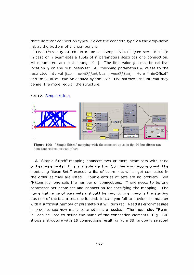
three di�erent connection types. Select the concrete type via the drop-down
list at the bottom of the component.
The �Proximity Stitch� is a tamed �Simple Stitch� (see sec. 6.8.12):
In case of n beam-sets a tuple of n parameters describes one connection.
All parameters are in the range [0, 1]. The �rst value p1 sets the relative
location l1 on the �rst beam-set. All following parameters pn relate to the
restricted interval [ln−1 − minOffset, ln−1 + maxOffset]. Here �minO�set�
and �maxO�set� can be de�ned by the user. The narrower the interval they
de�ne, the more regular the structure.
6.8.12. Simple Stitch
Figure 100: ”Simple Stitch”-mapping with the same set-up as in fig. 96 but fifteen ran-dom connections instead of two.
A �Simple Stitch�-mapping connects two or more beam-sets with truss
or beam-elements. It is available via the �Stitches�-multi-component.The
input-plug �BeamSets� expects a list of beam-sets which get connected in
the order as they are listed. Double entries of sets are no problem. Via
�NConnect� one sets the number of connections. There needs to be one
parameter per beam-set and connection for specifying the mapping. The
numerical range of parameters should be zero to one: zero is the starting
position of the beam-set, one its end. In case you fail to provide the mapper
with a su�cient number of parameters it will turn red. Read its error-message
in order to see how many parameters are needed. The input plug �Beam
Id� can be used to de�ne the name of the connection elements. Fig. 100
shows a structure with 15 connections resulting from 30 randomly selected
127

parameters.
This �simple�-variant of stitches is also the most versatile one: it gives
you great freedom in generating connection patterns by de�ning the way
how a set of parameters is mapped to the set of values that are fed into the
�Simple Stitch�. Sections 6.8.11 and 6.8.13 deal with variants of the �Simple
Stitch� which are limiting the scope of possible patters. This approach leads
to faster convergence in case of optimization with e.g. Galapagos and spares
you programming e�ort but lacks the full �exibility of the �Simple Stitch�.
6.8.13. Stacked Stitch
Figure 101: ”Stacked Stitch”-mapping with the same set-up as in fig. 96 but fifteenrandom connections instead of two.
A �Stacked Stich�-component works along the same lines as a �Simple
Stitch�. The di�erence is, that it maps the given parameters to a geometry in
such a way, that no two connection elements cross each other (see �g. 101).
The input-plug �unevenness� can be used to �ne-tune the average irregularity
of the result. Zero means totally even: the connection elements are placed
at equal distance along the beam-sets (in terms of the corresponding beam-
set parameter). The larger the value in �unevenness� the more irregular the
layout of connection elements.
6.8.14. User Iso-Lines and Stream-Lines
The components �User Iso-Lines� and �User Stream-Lines� let you draw iso-
lines and stream-lines on arbitrary meshes by de�ning values and vectors at
their vertices.
128

Figure 102: User defined Iso-lines (red) and stream-lines (green) on a rectangular shellpatch.
The de�nition �Shell_UserDe�nedIsoAndStreamLines.gh� in �..Libraries/-
Karamba/Examples/TestExamples/� uses a function which when given a
point returns the distance from and direction to a prede�ned source point
(see �g. 102).
Both components �User Iso-Lines� and �User Stream Lines� work similar
to the �IsoLines�- (see section 6.6.11) and �Principal Stress Lines on Shells�-
components (see section 6.6.11) respectively. The only di�erence lies in the
fact that for each node of the model (which includes also nodes that only
connect to beams) a value (input-plug �Vals�) or vector (input-plug �TVecs�)
tangent to the �ow needs to be supplied.
7. Trouble shooting
Do not panic in case some Karamba-components turn red upon feeding them
with your model. Read the error message. It usually contains information
that helps you further. A very e�cient technique for tracking errors is to
divide and conquer:
1. Split the model in half.
2. Check both parts.
3. Scrutinize the part that does not work.
129

4. See whether you can �nd an error in it.
5. If not take that part as your new model and proceed to point 1.
7.1. Karamba does not work for unknown reason
This is the recommended procedure:
1. If a component turns red read its runtime-error-message.
2. In case that more than one item is plugged into an input, check the
incoming data via a panel component.
3. Sometimes �attening the input data helps: The dimension of input-lists
must be consistent. For diagnosis plug them into a Panel-component
which will show the dimensionality of the data. Another method is
to enable �Draw Fancy Wires� in the View menu: Di�erently outlined
connection lines signify di�erent dimensionality of the data that �ows
through them.
4. If no results show, check whether preview is enabled on the ModelView,
BeamView or ShellView-component.
5. If the Analyze-component reports a kinematic structure do the follow-
ing:
� Check the supports for forgotten support conditions.
� Start to �x all degrees of freedom on your supports until the
Analyze-component reacts.
� Introduce additional supports.
� Plug the model into the EigenModes-component. The �rst eigen-
modes will be the rigid body modes you forgot to �x. Save your
model before doing that: Large models can take a long time to
calculate.
� If the �rst few eigen-modes seemingly show an un-de�ected struc-
ture there might be beams in the system that rotate about their lon-
gitudinal axis. Enable �Local Axes� in the ModelView-component
and move the slider for scaling Deformation in order to check this.
130

� Turn trusses into beams by activating their bending-sti�ness. Be
aware of the fact that a node has to be �xed by at least three
trusses that do not lie in one plane.
� Remember that trusses have no torsional or bending sti�ness and
thus can not serve to �x the corresponding rotations on a beam
that attaches to the same node.
� Check whether an element has zero area, height or Young's mod-
ulus.
7.2. �fem.karambaPINVOKE�-exception
On some computers the analysis component of Karamba refuses to work and
throws a �fem.karambaPINVOKE� exception. This may be due to left-overs
from previous Karamba installations which were not removed properly during
the installation procedure. In such a case precede as follows:
� Uninstall Karamba completely via settings/Software/...
� Make sure that everything was removed:
� Remove �karamba.dll� and �libiomp5md.dll� from the windows folder
if they sill exist.
� Search your hard-disk for �karamba.dll�- and �karamba.gha�-�les and
remove all occurrences by hand.
� reinstall Karamba.
If this does not help do the following:
� Check whether the �karamba.dll� '-�le in the �Windows�-folder is blocked:
right-click on the �le and select �Properties� then security.
� Make sure that you installed a Karamba version with the correct bitness:
Karamba (64bit) can be used together with �Rhinoceros 5 (64bit)�;
Karamba (32bit) with �Rhinoceros 5�. Be aware of the fact that both
versions of Rhino get installed.
This is plan b if the above does not help:
131

� Start Grasshopper
� Type �GrasshopperDeveloperSettings� in the Rhino Window and hit
�ENTER�
� Toggle the status of the �Memoryload *.GHA assemblies using COFF
byte arrays� option
� Restart Rhino
Plan c is to post a help request to the Karamba group at http://www.
grasshopper3d.com/group/karamba.
7.3. The StackedStitch-components renders structures with
overlapping diagonals
Beam-sets have an orientation. You probably use beam-sets with opposing
directions.
7.4. Karamba does not work after reinstalling Grasshoper
Upon installing Grasshopper some �les of the Karamba package may have
been erased. Try to reinstall Karamba.
7.5. Karamba does not appear nor any of its components seem to
be installed
In case of multiple versions of Grasshopper on your machine make sure that
you installed Karamba to that Grasshopper version which is used by Rhino. In
Rhino select �Tools/Options.../Plug-ins� from the menu, then �Grasshopper�
from the list of plug-ins. Press the �Properties...�-button to check the path
to Grasshopper.
Multiple Grasshopper versions can result if there are more than one users
on a machine and each of them installs his or her own Grasshopper.
132

7.6. Karamba seems to get stuck while calculating a model
Depending on your computer (CPU, size of internal memory) Karamba can
handle models in the order of 10000 elements e�ciently. If overlong com-
putation times occur check the number of models you actually calculate.
Having the path structures of the input-data wrong may lead to multiple
models. In such cases �attening or simplifying the input-data helps.
7.7. Prede�ned displacements take no e�ect
Check whether you disabled the correct degrees of freedom in the �Condi-
tions� section of the PreDisp-component.
7.8. The ModelView-component consistently displays all load cases
simultaneously
If the ModelView-component does not seem to react to selections done with
the drop-down-list for load cases, check the value in the �LC-Index�-input
plug. Remember that its value is added to the load case index selected on
the drop-down-list. If the sum is negative all load cases will be displayed.
7.9. The View-components do not show rendered meshes (stress,
strain,...), supports, etc.
Check whether �Shaded Preview� is enabled in Grasshoppers Solution menu.
7.10. The ModelView-component does not display any tags
Check whether your Rhino background color is black. Some types of tags
are printed in black and do not show on a black canvas. You can change the
text color in the 'karamba.ini�-�le (see section 3).
7.11. Circular cross sections show up as �at stripes when rendered
Set the �Faces/Cross section� slider of the �ModelView�-component to a
value larger than two such that the displayed result su�ciently corresponds
to your idea of roundness.
133

7.12. Icons in �Karamba�-toolbar do not show up
Sometimes it happens that Karambas component panels do not display any
component icons. Select menu item �View/Show all components� in order
to make them show up.
7.13. Error messages upon loading de�nitions saved with outdated
Karamba versions
When loading de�nitions based on outdated Karamba version a pop-up win-
dow will inform you that �IO generated x messages,...�. Normally this can
be ignored. It may happen however that very old Karamba components do
not load. In this case put their current versions in place. Deprecated com-
ponents issue a warning-message (turn orange). In case you enable �Draw
Icons� in Grasshoppers �View� menu, deprecated components are marked by
a skull.
7.14. Component in old de�nition reports a run-time error
On some components the order of input-plugs changed over time (e.g. the
Assemble-component). They will turn red when loaded and the runtime error
message will state that one object can not be cast to some other object.
In this case replace the old component with a new one and reattach the
input-plugs accordingly.
7.15. The �Optimize Cross Section�-component does not work
Make sure that the beams you intend to optimize belong to the same family
as those you want them to be selected from.
7.16. The �Optimize Cross Section�-component returns wrong
results
Increase the value at the �iter�-input-plug. The cross section optimization
algorithm is an iterative procedure. In case you stop too early � having
limited the maximum number of iterations to a small value � the algorithm
134

has no chance to converge and thus returns seemingly wrong results. Always
check the �Info�-output of the component for information on the solution
procedure.
7.17. Other problems
In case you encounter any further problems please do not hesitate to con-
tact us at [email protected] or via the Karamba group at http://www.
grasshopper3d.com/group/karamba.
135

A. Background information
A.1. Basic Properties of Materials
A.1.1. Material Sti�ness
The sti�ness i.e. resistance of a material against deformation is characterized
by its Young's Modulus or modulus of elasticity E. The higher its value
the sti�er the material. Table 2 lists E-values for some popular building
materials.
type of material E[kN/cm2]
steel 21000aluminum 7000reinforced concrete 3000glass �ber 7000wood (spruce) 1000
Table 2: Young’s Modulus of materials
For composite materials � like in the case of rods made from glass �ber
and epoxy � it is necessary to defer a mean value for E using material tests.
Karamba expects the input for E to be in kilo Newton per square centimeter
[kN/cm2].
If one stretches a piece of material it not only gets longer but also thinner:
it contracts laterally. In case of steel for example lateral strain amounts to
30% of the longitudinal strain. In case of beams with a large ratio of cross
section height to span this e�ect in�uences the displacement response. In
common beam structures however this e�ect is of minor importance. The
shear modulus �G� describes material behavior in this respect.
A.1.2. Speci�c Weight
The value of �gamma� is expected to be in kilo Newton per cubic meter
[kN/m3]. This is a force per unit of volume. Due to Earths gravitational
acceleration (a = g = 9.81[kg ·m/s2]) and according to Newtons law (f = m ·a)a mass m of one kilogram acts downwards with a force of f = 9.81N . For
136

calculating de�ections of structures the assumption of f = 10N is accurate
enough. Table 3 gives speci�c weights of a number of typical building mate-
rials. The weight of materials only takes e�ect if gravity is added to a load
case (see section 6.4.1).
A.1.3. Theoretical Background of Sti�ness, Stress and Strain
As mentioned in section 6.5.1 strain is the quotient between the increase
of length of a piece of material when loaded and its initial length. Usually
one uses the Greek letter ε for strains. Strain induces stress in a material.
Stress is force per unit of area. From the stress in an beam cross-section one
can calculate the normal force that it withstands by adding up (integrating)
the product of area and stress in each point of the cross-section. Stress is
normally symbolized by the Greek letter σ. Linear elastic materials show a
linear dependence between stress and strain. The relation is called Hooke's
Law and looks like this:
σ = E · ε
E stands for Young's Modulus which depends on the material and depicts its
sti�ness. Hooke's law expresses the fact that the more you deform something
the more force you have to apply.
A.2. Additional Information on Loads
Karamba expects all force-de�nitions to be in kilo Newton (kN). On earth
the mass of 100kg corresponds to a weight force of roughly 1kN . The exact
number would be 0.981kN but 1kN is normally accurate enough. Table 3
contains the speci�c weight of some everyday materials. Rules of thumb
numbers for loads can be found in table 4. Do not take these values too
literally. For example snow loads vary strongly depending on the geographical
situation.
Loads acting along lines or on a speci�ed area can be approximated by
point-loads. All you need to do is estimate the area or length of in�uence
for each node and multiply it with the given load value. The Mesh-Load-
component (see section 6.4.7) automates this task for surface loads.
137

type of material [kN/m3]
reinforced concrete 25.0glass 25.0steel 78.5aluminum 27.0�r wood 3.2snow loose 1.2snow wet 9.0water 10.0
Table 3: Specific weights of some building materials
loads
type [kN/m2]
life load in dwellings 3.0life load in o�ces 4.0snow on horizontal plane 1.0cars on parking lot (no trucks) 2.5trucks on bridge 16.7
Table 4: Loads for typical scenarios
A.3. Tips for Designing Statically Feasible Structures
Karamba can be used to analyze the response of structures of any scale.
When using the �Analysis�-component for assessing the structural behavior
be aware of two preconditions: First de�ections are small as compared to
the size of the structure. Second materials do behave in a linear elastic
manner � i.e. a certain increase of deformation is always coupled to the
same increase of load. Real materials behave di�erently: they weaken at
some point and break eventually. If you want to calculate structures with
large de�ections you have to increase the load in several steps and update
the de�ected geometry. This can be done with the �Large Deformation
Analysis�-component (see section 6.5.3)
For typical engineering structures the assumptions mentioned above su�ce
for an initial design. In order to get meaningful cross section dimensions limit
138

Figure 103: Simply supported beam.
the maximum de�ection of the structure.
Figure 103 shows a simply supported beam of length L with maximum
de�ection ∆ under a single force at mid-span. The maximum de�ection of a
building should be such that people using it do not start to feel uneasy. As a
rough rule of thumb try to limit it to ∆ ≤ L/300. If your structure is more like
a cantilever ∆ ≤ L/150 will do. This can always be achieved by increasing the
size of the cross-section. If de�ection is dominated by bending (like in �gure
103) it is much more e�cient to increase the height of the cross-section than
its area (see section 6.1.10). Make sure to include all signi�cant loads (dead
weight, live load, wind...) when checking the allowable maximum de�ection.
For a �rst design however it will be su�cient to take a multiple of the dead-
weight (e.g. with a factor of 1.5). This can be done in Karamba by giving
the vector of gravity a length of 1.5.
In case of structures dominated by bending, collapse is preceded by large
de�ections (see for example the video of the collapse of the Tacoma-Narrows
bridge at http://www.youtube.com/watch?v=3mclp9QmCGs which also gives an
impression of what normal shapes are). So limiting de�ection automatically
leads to a safe design. If however compressive forces initiate failure, col-
lapse may occur without prior warning. The phenomenon is called buckling.
In Karamba it makes no di�erence whether an axially loaded beam resists
compressive or tensile loads: it either gets longer or shorter and the abso-
lute value of its change of length is the same. In real structures the more
slender a beam the less compressive force it takes to buckle it. An extreme
example would be a rope. As a rule of thumb limit the slenderness � which
is approximately the ratio of free span to diameter � of compressed elements
to 1/100.
139

A.4. Hints on Reducing Computation Time
Karamba spends most of its time solving for the de�ections of a model.
The time needed depends on the number of degrees of freedom n of the
statical system and how many connections exist between the nodes. In
the theoretical case that each node is connected to all others computation-
time grows with n3. If each node is connected to nneigh others and the
overall structure has a main axis along which it is oriented (i.e. there are
no connections between distant nodes) then computational e�ort increases
approximately with 0.5 · n · n2neigh. Karamba makes use of multiple processors
so having more than one saves time. Using trusses instead of beams more
than halves computation time. When doing optimization with Galapagos
the continuous display updates slow down things considerably. For better
performance disable the preview of all components or minimize the Rhino
window.
A.5. Natural Vibrations, Eigen Modes and Buckling
The Eigen-modes of a structure describe the shapes to which it can be
deformed most easily in ascending order. The �rst mode is the one which
can be achieved most easily. The higher the mode number the more force
has to be applied. An Eigen-mode ~x is the solution to the matrix-equation
C˜ · ~x = λ · ~x which is called the special eigen-value problem. Where C˜ is a
matrix, ~x a vector and λ a scalar (that is a number) called eigen-value. The
whole thing does not necessarily involve statical structures. Eigen-modes and
eigen-values are intrinsic properties of a matrix. When applied to structures
then C˜ stands for the sti�ness-matrix whose number of rows and columns
corresponds to the number of degrees of freedom of the statical system. ~x
is an eigen-mode as can be computed with Karamba.
Vibration modes ~x of structures result from the solution of a general
Eigenvalue problem. This has the form C˜ · ~x = ω2 ·M˜ · ~x. In a structural
context M˜ is the mass-matrix which represents the e�ect of inertia. The
scalar ω can be used to compute the eigen-frequency f of the dynamic
system from the equation f = ω/2π. In the context of structural dynamics
eigen-modes are also called normal-modes or vibration-modes.
140

The �Buckling Modes�-component calculates the factor with which the
normal forces N II need to be multiplied in order to cause structural instability.
The buckling factors are the eigenvalues of the general Eigenvalue problem
C˜ ·~x+λ2 ·CG˜ ·~x = 0. Here C˜ is the elastic sti�ness matrix and CG˜ the geometric
sti�ness matrix. The latter captures the in�uence of normal forces N II on
a structures deformation response.
A.6. Approach Used for Cross Section Optimization
Karamba does cross section design by going through the list of cross sections
in a group of cross sections called a family. It starts at the �rst entry and
proceeds to the next until a cross section is found that is su�cient for the
given cross section forces.
The calculation of the utilization of a beam is done using the procedure
described in EN 1993-1-1 i.e. Eurocode (EC) 3. It takes account of buckling
and lateral torsional buckling. The superposition of di�erent cross section
forces works according to procedure 2 (see annex B of EC 3). The values
Cmy, Cmz and CmLT are limited to 0.9. The Utilization components �Details�-
output returns a listing of intermediate values from the calculation according
to EC3 (see section 6.6.6).
References
[1] J. H. Argyris, L. Tenek, and L. Olofsson. Tric: a simple but sophisticated
3-node triangular element based on 6 rigid.body and 12 straining modes
for fast computational simulations of arbitrary isotropic and laminated
composite shells. Comput. Methods Appl. Mech. Engrg., 145:11�85,
1997.
[2] J.H. Argyris, M. Papadrakakis, C. Apostolopoulou, and S. Koutsourelakis.
The tric shell element: theoretical and numerical investigation. Comput.
Methods Appl. Mech. Engrg., 182:217�245, 2000.
[3] X. Huang and M. Xie. Evolutionary Topology Optimization of Continuum
Structures: Methods and Applications. Wiley, 2010.
141

[4] Rubin H. Schneider K.-J. Baustatik Theorie I. und II. Ordnung. Werner-
Verlag, 1996.
[5] H. Moldenhauer. Die visualisierung des kraft�usses in stahlbaukonstruk-
tionen. Stahlbau, Ernst & Sohn Verlag für Architektur und technische
Wissenschaften GmbH & Co. KG, Berlin, 81:32�40, 2012.
142