Embed Size (px)
DESCRIPTION
Karamba
Citation preview
Peer-reviewed by international ex-perts and accepted for publication by SEI Editorial Board
Paper received: July 15, 2013Paper accepted: November 18, 2013
Structural Engineering International 2/2014 Scientific Paper 217
Karamba—A Toolkit for Parametric Structural DesignClemens Preisinger, Dipl.-Ing., Dr., University of Applied Arts Vienna, Structural Design, Vienna, Austria;
Moritz Heimrath, Mag. Arch., Bollinger Grohmann Schneider ZT GmbH, Research and Development, Vienna, Austria.
Contact: [email protected]
DOI: 10.2749/101686614X13830790993483
Abstract
An increasing number of architectural design practices harness the power of parametric design tools. The aim of these tools is to facilitate and control com-plex building geometries. Parametric design programs such as Grasshopper (GH) for Rhino or Generative Components popularized this approach by pro-viding easy-to-use visual programming environments that integrate with com-puter-aided design (CAD) packages. A logical next step consists in connecting parametric designs to applications that evaluate non-geometric aspects such as building physics or structural performance. This brings about new opportunities of collaboration between architects and engineers in the early stages of build-ing design. The ease of testing alternatives by tweaking a set of parameters also opens the door for the application of generic optimization algorithms. Karamba is a finite element program geared towards interactive use in the parametric design environment GH. Being a GH plug-in, it seamlessly integrates with the diverse habitat of other third party programs available for GH. These range from build-ing physics applications to genetic optimization engines. In the author’s company, Karamba is used in early-stage design, form-finding, and structural optimization. “White Noise”, a mobile exhibition pavilion for the Salzburg Biennale, serves as a case study that shows how Karamba can be used to optimize the structural performance of intricate building geometries.
Keywords: parametric design environment; structural; inter active; finite elements; optimization; integrated planning process.
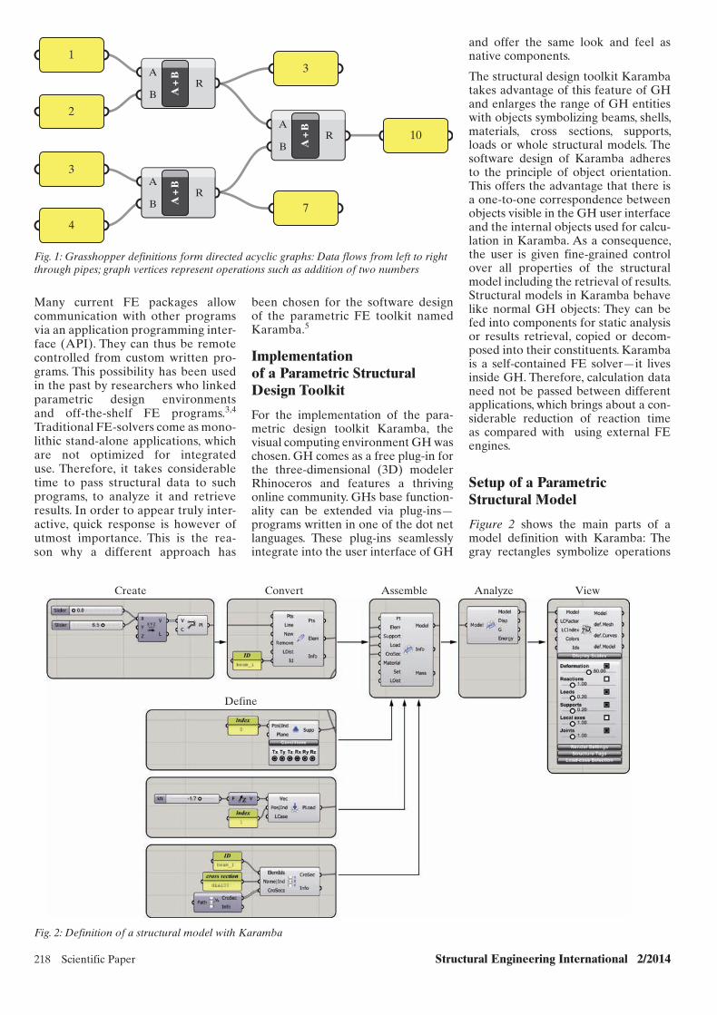
drawing. One early approach consisted in recording the history of commands that lead to a given geometry. The command history implicitly stores the dependencies between the objects of a drawing. It can be used to update elements (e.g. lines) when their par-ent entities from which they derive (e.g. points) change. This offers flex-ibility with respect to the input param-eters (e.g. point coordinates): A series of commands can be automatically re-executed in a preset order to cre-ate an altered version of the original geometry.
The next step in enhancing flexibility of geometry creation consisted in mak-ing the history explicit and letting the user control the order of commands. Current parametric design environ-ments such as Generative Components (GC)1 or Grasshopper (GH)2 imple-ment that idea. They provide the user with a visual environment where commands can be linked together to form a directed acyclic graph (Fig. 1): Data flows through the graph edges (visualized as pipes) from left to right and gets processed at the vertices that
symbolize operations. Figure 1 shows a simple case where a GH definition is used to sum up four user-defined numbers. Algorithms formulated in such a way lack features of traditional programming languages such as loops. This makes them easier to learn and enables users to express geometric production rules without the need of having to think in terms of a program-ming language. When necessity arises though, GH definitions can be supple-mented by custom scripts (devised in C# or Visual Basic) that provide a higher level of expressiveness.
Parametric Structural Design
Currently, parametric design strate-gies focus on the generation of geom-etries—primarily in an architectural context. They allow the user to test a large number of different but related geometries without much effort. This is most important in early design stages where a complex network of contra-dicting architectural objectives needs to be considered for finding the best solution.
Presently, applications of paramet-ric tools in structural design remain scarce. This is rooted in the traditional approach to building projects where architects hand over a “frozen” geom-etry for further analysis to structural engineers. Typical finite element (FE) programs are geared toward thor-ough analysis of a given structure that does not change significantly in the course of design. The current trend of increased complexity of architectural designs entails the need to incorporate structural assessment early on. The ideal solution would be an automated feedback loop between architectural design and structural response in real time: An architect changes the param-eters of his or her design and receives immediate response regarding the impact on structural performance. In later project stages, flexibility and tolerance toward changes are no less beneficial as in practice architectural designs tend to change even after being frozen.
Introduction
Digital tools have transformed the process of architectural and struc-tural design tremendously since they superseded the drawing board about 20 years ago. One feature that remained constant though, is the fact that designs tend to change signifi-cantly from conception to completion. Therefore, increased flexibility consti-tutes the key feature that motivates the adoption of new design technolo-gies: Computer-aided design (CAD) programs became popular because they allowed to change a digital draw-ing with a few clicks of a mouse instead of having to use a razor blade on a large sheet of paper.
Later on, flexibility was further enhanced by adding context informa-tion to the constituents of a digital
218 Scientific Paper Structural Engineering International 2/2014
and offer the same look and feel as native components.
The structural design toolkit Karamba takes advantage of this feature of GH and enlarges the range of GH entities with objects symbolizing beams, shells, materials, cross sections, supports, loads or whole structural models. The software design of Karamba adheres to the principle of object orientation. This offers the advantage that there is a one-to-one correspondence between objects visible in the GH user interface and the internal objects used for calcu-lation in Karamba. As a consequence, the user is given fine-grained control over all properties of the structural model including the retrieval of results. Structural models in Karamba behave like normal GH objects: They can be fed into components for static analysis or results retrieval, copied or decom-posed into their constituents. Karamba is a self-contained FE solver—it lives inside GH. Therefore, calculation data need not be passed between different applications, which brings about a con-siderable reduction of reaction time as compared with using external FE engines.
Setup of a Parametric Structural Model
Figure 2 shows the main parts of a model definition with Karamba: The gray rectangles symbolize operations
been chosen for the software design of the parametric FE toolkit named Karamba.5
Implementation of a Parametric Structural Design Toolkit
For the implementation of the para-metric design toolkit Karamba, the visual computing environment GH was chosen. GH comes as a free plug-in for the three-dimensional (3D) modeler Rhinoceros and features a thriving online community. GHs base function-ality can be extended via plug-ins—programs written in one of the dot net languages. These plug-ins seamlessly integrate into the user interface of GH
Many current FE packages allow communication with other programs via an application programming inter-face (API). They can thus be remote controlled from custom written pro-grams. This possibility has been used in the past by researchers who linked parametric design environments and off-the-shelf FE programs.3,4
Traditional FE-solvers come as mono-lithic stand-alone applications, which are not optimized for integrated use. Therefore, it takes considerable time to pass structural data to such programs, to analyze it and retrieve results. In order to appear truly inter-active, quick response is however of utmost importance. This is the rea-son why a different approach has
13
7
10
2
3
4
A
BR
A +
BA
BR
A +
B
A
BR
A +
B
Fig. 1: Grasshopper definitions form directed acyclic graphs: Data flows from left to right through pipes; graph vertices represent operations such as addition of two numbers
Create Convert
Define
Assemble Analyze View
Fig. 2: Definition of a structural model with Karamba
Structural Engineering International 2/2014 Scientific Paper 219
finished structure, a prestressed mem-brane, shields visitors from wind and rain. This surface may not be crossed by structural members and thus deter-mined their starting points. In order to arrive at a structure of uniform visual density, the inner starting points of rods were positioned at uniform mutual distance with a phase shift between neighboring layers (Fig. 4). The incli-nation of the aluminum rods should differ within a certain range, following global rules for aggregation and allow-ing for an individual behavior. The aim was to keep the visitors’ focus switch-ing between single members and the integrated whole. The aluminum rods had to adhere to the condition that no two members of the same layer over-lap. This constraint came from the side of architectural design. Figure 4 shows how the members of neighboring lay-ers (colored blue and red) are joined to each other: where two members cross they get connected via circular studs (symbolized in the drawing as black circles). The structural perfor-mance of the pavilion thus depended heavily on the relative position of the aluminum rods.
Based on the given geometry of the inner hull and the constraints for-mulated above, a parametric model was set up in GH. Twenty parameters controlled the orientation of the alu-minum rods. The positions of the con-necting circular studs between them were determined using GHs geometric analysis capabilities.
For each of the five main parts, a static model was created using Karamba. Although different in shape, one basic setup for geometry and structural
form-finding processes or optimization strategies.
Application to Real-World Structures
In the structural engineering office, Karamba can be used at all stages of project development: from structural assessment of architectural competi-tion entries to design development and generation of construction documents. The project “White Noise” will be used to describe how Karamba fits into the structural design process.
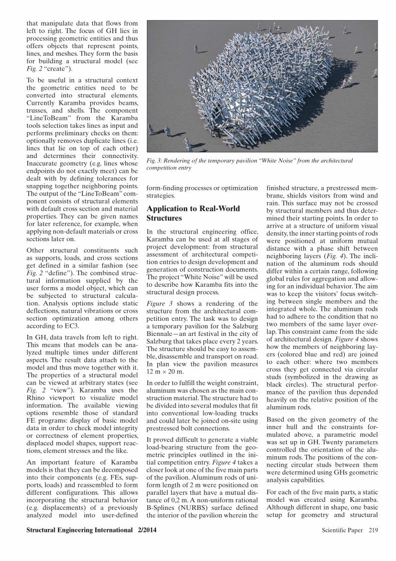
Figure 3 shows a rendering of the structure from the architectural com-petition entry. The task was to design a temporary pavilion for the Salzburg Biennale—an art festival in the city of Salzburg that takes place every 2 years. The structure should be easy to assem-ble, disassemble and transport on road. In plan view the pavilion measures 12 m × 20 m.
In order to fulfill the weight constraint, aluminum was chosen as the main con-struction material. The structure had to be divided into several modules that fit into conventional low-loading trucks and could later be joined on-site using prestressed bolt connections.
It proved difficult to generate a viable load-bearing structure from the geo-metric principles outlined in the ini-tial competition entry. Figure 4 takes a closer look at one of the five main parts of the pavilion. Aluminum rods of uni-form length of 2 m were positioned on parallel layers that have a mutual dis-tance of 0,2 m. A non-uniform rational B-Splines (NURBS) surface defined the interior of the pavilion wherein the
that manipulate data that flows from left to right. The focus of GH lies in processing geometric entities and thus offers objects that represent points, lines, and meshes. They form the basis for building a structural model (see Fig. 2 “create”).
To be useful in a structural context the geometric entities need to be converted into structural elements. Currently Karamba provides beams, trusses, and shells. The component “LineToBeam” from the Karamba tools selection takes lines as input and performs preliminary checks on them: optionally removes duplicate lines (i.e. lines that lie on top of each other) and determines their connectivity. Inaccurate geometry (e.g. lines whose endpoints do not exactly meet) can be dealt with by defining tolerances for snapping together neighboring points. The output of the “LineToBeam” com-ponent consists of structural elements with default cross section and material properties. They can be given names for later reference, for example, when applying non-default materials or cross sections later on.
Other structural constituents such as supports, loads, and cross sections get defined in a similar fashion (see Fig. 2 “define”). The combined struc-tural information supplied by the user forms a model object, which can be subjected to structural calcula-tion. Analysis options include static deflections, natural vibrations or cross section optimization among others according to EC3.
In GH, data travels from left to right. This means that models can be ana-lyzed multiple times under different aspects. The result data attach to the model and thus move together with it. The properties of a structural model can be viewed at arbitrary states (see Fig. 2 “view”). Karamba uses the Rhino viewport to visualize model information. The available viewing options resemble those of standard FE programs: display of basic model data in order to check model integrity or correctness of element properties, displaced model shapes, support reac-tions, element stresses and the like.
An important feature of Karamba models is that they can be decomposed into their components (e.g. FEs, sup-ports, loads) and reassembled to form different configurations. This allows incorporating the structural behavior (e.g. displacements) of a previously analyzed model into user-defined
Fig. 3: Rendering of the temporary pavilion “White Noise” from the architectural competition entry

220 Scientific Paper Structural Engineering International 2/2014
Fig. 5: Calculated deflections at the beginning of the structural optimization procedure
model proofed sufficient for all five main parts. As the geometry of the inner hull constitutes just one more input parameter, it simply had to be switched from part to part with the rest of the parametric definition remaining unchanged.
Figure 5 shows an axis model of the initial geometry (red) and the deformed structure (yellow) with mag-nified deflections. The green arrows at the base of the structure represent supports against nodal translations. Wind in horizontal direction proved to be the governing load case in most situations, but also the loads from the
prestressed membrane contributed significantly to the stress in the ele-ments and connections.
For each of the partial models, the 20 free parameters had to be determined in such a way that neither usability was impaired by large deflections nor stresses in the elements and connec-tions exceeded the allowable limit. There exists no continuously differen-tiable relationship between the inclina-tion of the aluminum rods and overall structural performance because the number of connections changes in a stepwise fashion. Owing to the open platform philosophy of GH, there are
several solvers freely available that can handle such problems efficiently. For the job at hand, a genetic algorithm solver called “Galapagos”7 was used. Genetic algorithm procedures8 work along the principles of natural selec-tion. They breed solutions from an ini-tial, randomly generated population of parameter sets. By evaluating a large number of solutions with respect to a fitness function, genetic algorithms gradually converge to reasonably good solutions even for very difficult problems.
In the case of the White Noise pavilion, three criteria were considered for driv-ing the optimization process:
1. Largest displacement dmax in the structure under exterior loads—to be minimized to ensure serviceability.
2. Number of connections ncon between the aluminum rods—to be minimized in order to lower produc-tion effort and cost.
3. A global variation value vvar, which measured the difference of inclina-tion of neighboring members—to be maximized for esthetic reasons.
In order to feed the genetic algorithm solver with a single fitness function, the three criteria were combined using the following heuristic formula:
Fitness = vvar/(dmaxncon)
The numbers of fitness evaluations for different sets of input parameters were in the range of several ten thousands. One optimization run took roughly 4 h on a quad-core workstation.
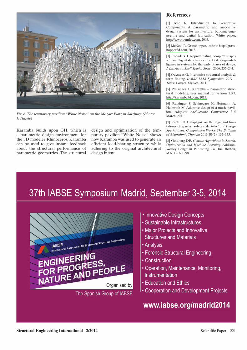
Figure 6 shows the pavilion White Noise after completion on the Mozart Platz in Salzburg. A comparison with the initial competition rendering in Fig. 3 proves that the structure could be realized according to the architect’s design intent.
Conclusions
Parametric visual design environments provide a powerful, flexible tool for defining and handling complex geom-etries. They enable users to express their general idea about structural shapes in an algorithmic way without the need to resort to formal program-ming languages. Owing to their depen-dence on parameters, algorithmically defined geometries can be changed easily: either interactively in order to study the architectural qualities of alternatives or automatically in combi-nation with optimization engines. The parametric structural design toolkit
Fig. 4: The load carrying structure consists of parallel layers of differently inclined aluminum rods that connect to each other via circular studs
Structural Engineering International 2/2014 Scientific Paper 221
Fig. 6: The temporary pavilion “White Noise” on the Mozart Platz in Salzburg (Photo: F. Hafele)
Karamba builds upon GH, which is a parametric design environment for the 3D modeler Rhinoceros. Karamba can be used to give instant feedback about the structural performance of parametric geometries. The structural
design and optimization of the tem-porary pavilion “White Noise” shows how Karamba was used to generate an efficient load-bearing structure while adhering to the original architectural design intent.
References
[1] Aish R. Introduction to Generative Components, A parametric and associative design system for architecture, building engi-neering and digital fabrication. White paper, http://www.bentley.com, 2005.
[2] Mc Neel R. Grasshopper. website http://grass-hopper3d.com, 2013.
[3] Coenders J. Approximating complex shapes with intelligent structures: embedded design intel-ligence in systems for the early phases of design. J. Int. Assoc. Shell Spatial Struct. 2006; 237–244.
[4] Odysseas G. Interactive structural analysis & form finding. IABSE-IASS Symposium 2011 – Taller, Longer, Lighter, 2011.
[5] Preisinger C. Karamba – parametric struc-tural modeling, user manual for version 1.0.3. http://karamba3d.com, 2013.
[6] Rutzinger S, Schinegger K, Hofmann A, Heimrath M. Adaptive design of a music pavil-ion. Adaptive Architecture Converence 3–5 March, 2011.
[7] Rutten D. Galapagos: on the logic and limi-tations of generic solvers. Architectural Design Special issue: Computation Works: The Building of Algorithmic Thought 2013; 83(2): 132–135.
[8] Goldberg DE. Genetic Algorithms in Search, Optimization and Machine Learning, Addison-Wesley Longman Publishing Co., Inc. Boston, MA, USA 1998.
The Spanish Group of IABSE
www.iabse.org/madrid2014
• Innovative Design Concepts • Sustainable Infrastructures• Major Projects and Innovative Structures and Materials• Analysis• Forensic Structural Engineering• Construction• Operation, Maintenance, Monitoring, Instrumentation • Education and Ethics• Cooperation and Development Projects
Madrid, September 3-5, 201437th IABSE Symposium
Organised by