Embed Size (px)
Citation preview

This information may be subject to change. All brand and product names are trademarks and/orregistered trademarks of their respective owners. All rights reserved.Copyright © 2001 by OPTICOM GmbH · www.opticom.de
User Manualfor the OPERA™ E1/T1 Option
OPR-002-E1T-P
C O N T E N T S
i
ContentsContents.............................................................................................................................................i
1 Preface......................................................................................................................................1
2 Setup of the Cable Connections...........................................................................................3
3 Setup of the E1/T1 Board Parameters ..................................................................................53.1 Configuration Parameters Overview...........................................................................5
3.1.1 Protocols ................................................................................................................53.1.2 Call Progress Tones..............................................................................................63.1.3 D-Channel Configuration.....................................................................................73.1.4 Line Code ...............................................................................................................73.1.5 T1 Framing Method..............................................................................................73.1.6 CAS ABCD Idle Pattern .......................................................................................73.1.7 Coding Law............................................................................................................83.1.8 Line Build Out........................................................................................................83.1.9 Destination Numbering Type..............................................................................83.1.10 Destination Numbering Plan ...............................................................................83.1.11 Source Numbering Type......................................................................................83.1.12 Source Number Presentation...............................................................................83.1.13 Source Number Screening ...................................................................................83.1.14 Source Phone Number..........................................................................................83.1.15 Source Phone Subnumber...................................................................................83.1.16 Transfer Capability ...............................................................................................93.1.17 Inter Exchange Prefix Number.............................................................................93.1.18 B-Channel Selection .............................................................................................9
3.2 Using the OptiConf™ Application.............................................................................93.2.1 The Parameter Field “Protocol Type”..............................................................103.2.2 The Parameter Field “Protocol Version”..........................................................103.2.3 The Parameter Field “Protocol Subversion”...................................................103.2.4 The Parameter Field “Call Progress Tones Conf.”.........................................113.2.5 The Parameter Field “DChannel Configuration”............................................113.2.6 The Parameter Field “Line Code” .....................................................................113.2.7 The Parameter Field “T1 Framing Method”....................................................113.2.8 The Parameter Field “CAS ABCD Idle Pattern”.............................................113.2.9 The Parameter Field “Coding Law” ..................................................................113.2.10 The Parameter Field “Line Build Out ”.............................................................113.2.11 The Parameter Field “Termination Side” .........................................................123.2.12 The Parameter Field "Set B-Channel Parameters"..........................................12
3.3 Setting up B-Channel Configuration Parameters ....................................................12
4 Signal Acquisition Using OptiCall™.................................................................................17
5 OptiCall™ Command Line Parameters ...............................................................................19
6 Measurement Examples .......................................................................................................216.1 Example Parameter Settings for Several Protocol Types........................................21
6.1.1 E1_Euro_ISDN ....................................................................................................216.1.2 T1_CAS................................................................................................................226.1.3 E1_MFCR2...........................................................................................................256.1.4 E1_CAS_R2 .........................................................................................................266.1.5 T1_NI2_ISDN......................................................................................................266.1.6 T1_5ESS_10_ISDN.............................................................................................286.1.7 T1_DMS100_ISDN.............................................................................................28
6.2 Example 1: Stand Alone Loop Measurement...........................................................296.3 Example 2: Measurements From a Batch File ...........................................................32

C O N T E N T S
ii
7 Options for Advanced Users..............................................................................................337.1 Editing a Call Progress Tones Configuration File ...................................................337.2 Editing a CAS Protocol Table ....................................................................................34
7.2.1 Overview..............................................................................................................347.2.2 Constructing or Modifying a CAS Protocol Table ........................................357.2.3 Table Elements ....................................................................................................357.2.4 State’s Line Structure .........................................................................................38
7.3 Protocol Trace Option.................................................................................................447.3.1 Tracing CAS/Robbed Bit Protocols .................................................................44
7.4 Downloadables Construction Utility ........................................................................467.4.1 Location................................................................................................................467.4.2 Description...........................................................................................................467.4.3 Operation..............................................................................................................46
8 Technical Specifications......................................................................................................47
9 References .............................................................................................................................48
10 Glossary of Terms ............................................................................................................4910.1 ANI.................................................................................................................................4910.2 CLI..................................................................................................................................49
C H A P T E R 1 : P R E F A C E
1
1 PrefaceThe documentation on hand is meant as a completion to the user manual ofthe OPERA™ measurement system. This documentation describes the E1/T1Option (OPR-002-E1T-P) for the OPERA™ voice quality analyzer. Before youstart reading this documentation, you should have studied the OPERA™ UserManual thoroughly, since the basic operation of components of the OPERA™system is assumed to be known in the following.
OPTICOM's E1/T1 interface option provides you with a large variety ofprotocols. In the current version the following protocol types are available:
E1 Euro ISDN,
E1 MFC-R2 CAS protocol including many country-specific variants,
E1 CAS-R2 protocol including R2D and R2D modified variants,
T1 CAS/Robbed Bit protocols including E&M wink start, E&Mimmediate start, E&M delay dial/start, loop start and ground start, and
T1 National ISDN-2 PRI protocol.
T1 ISDN implementations for particular switches are supported as
T1 ISDN PRI protocol for the Lucent®/AT&T® 4ESS switch,
T1 ISDN PRI protocol for the Lucent®/AT&T® 5ESS-9 switch,
T1 ISDN PRI protocol for the Lucent®/AT&T® 5ESS-10, and
T1 ISDN PRI protocol for the Nortel® DMS100 switch.
In addition, a number of transparent protocols are available that provide thephysical interface layer, without any signalling-related functions. Theprotocol types including all parameter settings for the interface board arefully software configurable.
With the E1/T1 Option for the OPERA™ voice quality analyzer, you maymodify the protocol parameters and even the entire state machine of T1CAS, E1 MFC-R2 and E1 CAS-R2 protocols. You may also create your owncall progress tones configuration files if the files provided by OPTICOMshould not meet your requirements.
In Section 2 of this document you will find a description of the boardhardware. Section 3 provides information about the setup process of theinterface board parameters, an overview of the available parameters andtheir meaning is given here. How to perform measurements with the E1/T1interface is explained in Section 4, the new command line parameters forautomated measurements from script files are described in Section 5.Measurement examples can be found in Section 6. Here, you will also findexample parameter settings for several protocol types.

C H A P T E R 1 : P R E F A C E
2
Advanced users will find descriptions for useful options in Section 7. Onthese pages, it is explained how to modify or construct CAS protocol tablesand how to edit call progress tones configurations. In addition, you willlearn how to trace protocols. The technical specifications for the interfaceboard are listed in Section 8. The documentation concludes with referencesand a glossary of terms in Sections 9 and 10.
C H A P T E R 2 : S E T U P O F T H E C A B L E C O N N E C T I O N S
3
2 Setup of the Cable ConnectionsThe E1/T1 Option for the OPERA™ voice quality analyzer enables you toperform measurements with digital PSTN systems like Primary Rate Access(PRA) to ISDN, E1 CAS/MFR2 protocols or T1 CAS/Robbed Bit protocols.
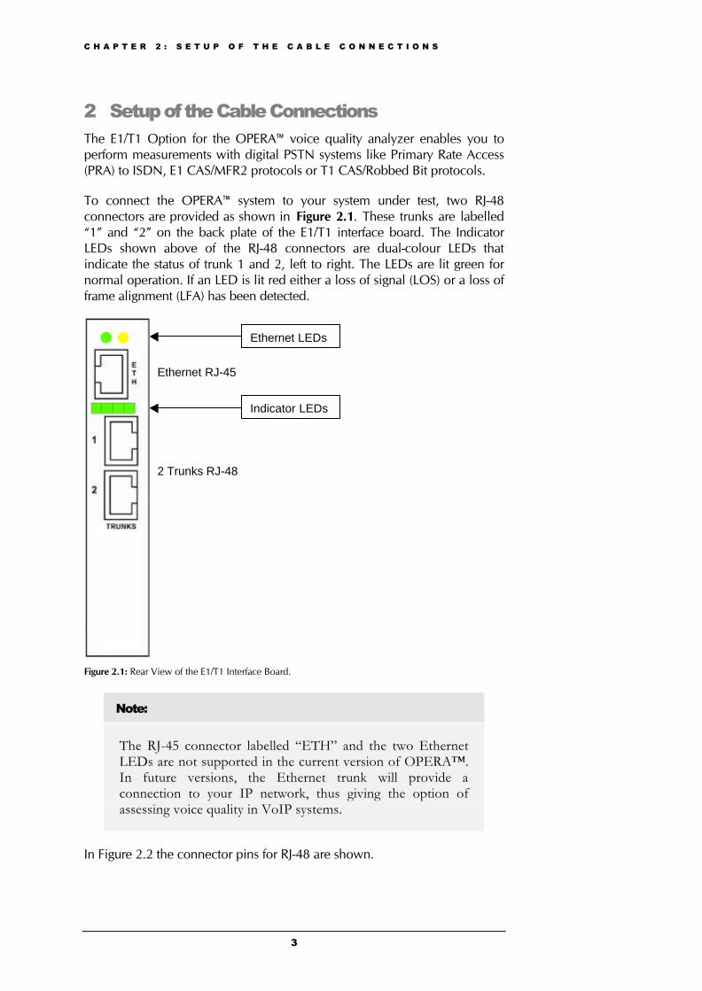
To connect the OPERA™ system to your system under test, two RJ-48connectors are provided as shown in Figure 2.1. These trunks are labelled“1” and “2” on the back plate of the E1/T1 interface board. The IndicatorLEDs shown above of the RJ-48 connectors are dual-colour LEDs thatindicate the status of trunk 1 and 2, left to right. The LEDs are lit green fornormal operation. If an LED is lit red either a loss of signal (LOS) or a loss offrame alignment (LFA) has been detected.
Figure 2.1: Rear View of the E1/T1 Interface Board.
Note:
The RJ-45 connector labelled “ETH” and the two EthernetLEDs are not supported in the current version of OPERA™.In future versions, the Ethernet trunk will provide aconnection to your IP network, thus giving the option ofassessing voice quality in VoIP systems.
In Figure 2.2 the connector pins for RJ-48 are shown.
Ethernet LEDs
Indicator LEDs
Ethernet RJ-45
2 Trunks RJ-48

C H A P T E R 2 : S E T U P O F T H E C A B L E C O N N E C T I O N S
4
Figure 2.2: RJ-48 Connector Pins
C H A P T E R 3 : S E T U P O F T H E E 1 / T 1 B O A R D P A R A M E T E R S
5
3 Setup of the E1/T1 Board ParametersBefore you will be able to start performing measurements with the E1/T1interface board, the board’s configuration parameters will have to be set up.These parameters affect the board’s operation. For instance, the protocoltype that is being used is defined at this point.
After the user has finished setting all necessary parameter values, theinitialization process is started during which the configuration parameter setis downloaded via the computer host’s PCI bus to the E1/T1 interface board.
Note:
The board configuration parameters are not “on-the-fly-changeable” in the sense that changes will only take effectafter the consecutive initialization process.
Please note, that after the start-up of the OPERA™ host PC, the last chosenparameter configuration set of the E1/T1 board is immediately available. Ifthis configuration meets your requirements, you may directly start theOptiCall™ application in order to perform measurements. For a descriptionof the OptiCall™ application, please refer to Section 4.
3.1 Configuration Parameters OverviewIn this section an overview of the available configuration parameters andtheir meaning is given. Only those parameters are described that will have tobe set up by the user.
3.1.1 ProtocolsThe E1/T1 Option for OPERA™ offers a large variety of protocol types whichare listed and described in the following.
E1 Euro-ISDN – ISDN PRI Pan-European (CTR4) protocol with manyinformation elements and call control messages.
E1 MFC-R2 - Common E1 MFC-R2 CAS protocols including line signallingand compelled register signalling. National variants such as for China, Israel,Mexico, Philippines and more are available. You may change the protocolparameters and even the entire state machine by editing the protocol textualtable that is downloaded to the E1/T1 interface board after the setup of theconfiguration parameters will have been finished. For a description of howto edit a CAS protocol table, please refer to Section 7.1.
E1 CAS-R2 - Common E1 CAS protocols including line signalling andMF/DTMF address transfer. Available are R2D and R2D modified variants.You may change the protocol parameters and the state machine by editingthe protocol textual table. For a description of how to edit a CAS protocoltable, please refer to Section 7.1.
C H A P T E R 3 : S E T U P O F T H E E 1 / T 1 B O A R D P A R A M E T E R S
6
T1 CAS – Common T1 robbed bit protocols including E&M wink start, E&Mimmediate start, E&M delay dial/start, loop start and ground start. You maychange the protocol parameters and the state machine by editing theprotocol textual table. For a description of how to edit a CAS protocol table,please refer to Section 7.1.
T1 NI2 ISDN - National ISDN-2 PRI protocol with many ISDN informationelements and call control messages.
T1 4ESS ISDN - ISDN PRI protocol for the Lucent®/AT&T® 4ESS switch withmany ISDN information elements and call control messages.
T1 5ESS-9 ISDN - ISDN PRI protocol for the Lucent®/AT&T® 5ESS-9 switchwith many ISDN information elements and call control messages.
T1 5ESS-10 ISDN - ISDN PRI protocol for the Lucent®/AT&T® 5ESS-10switch with many ISDN information elements and call control messages.
T1 DMS100 ISDN - ISDN PRI protocol for the Nortel® DMS100 switch withmany ISDN information elements and call control messages.
In addition to these protocol types, the E1/T1 Option for OPERA™ offers anumber of transparent protocols. Transparent protocols provide the physicalinterface layer, without any signalling-related functions. These protocol typesare listed below.
E1 Transparent-62 – Transparent protocol, where no signalling is to beprovided by the E1/T1 interface board. Time slots 1-31 of each trunk aremapped to the DSP channels hosted on the board. The first trunk is fullymapped, i.e. all 31 time slots, while the last trunk and its last time slots (30and 31) will not have any DSP channel.
E1 Transparent-60 - Transparent protocol, where no signalling is to beprovided by the E1/T1 interface board. Time slots 1-31, excluding time slot16 of both trunks, are mapped to 60 DSP channels on the board.
T1 TRANSPARENT - Transparent protocol, where no signalling is to beprovided by the E1/T1 board. Time slots 1-24 of both trunks are mapped to60 DSP channels.
J1 TRANSPARENT - Transparent protocol, where no signalling is to beprovided by the E1/T1 board. [AUDI01]
3.1.2 Call Progress TonesThe call progress tones to be detected, or generated by the board,respectively, are defined in a Call Progress Tones Configuration File. Youcan either use one of the files supplied by OPTICOM, or construct your ownfile. A description of how to edit a Call Progress Tones Configuration Filecan be found in Section 7.1.
C H A P T E R 3 : S E T U P O F T H E E 1 / T 1 B O A R D P A R A M E T E R S
7
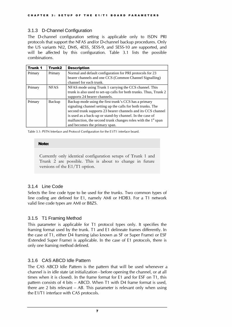
3.1.3 D-Channel ConfigurationThe D-channel configuration setting is applicable only to ISDN PRIprotocols that support the NFAS and/or D-channel backup procedures. Onlythe US variants NI2, DMS, 4ESS, 5ESS-9, and 5ESS-10 are supported, andwill be affected by this configuration. Table 3.1 lists the possiblecombinations.
Trunk 1 Trunk2 DescriptionPrimary Primary Normal and default configuration for PRI protocols for 23
bearer channels and one CCS (Common Channel Signalling)channel for each trunk.
Primary NFAS NFAS mode using Trunk 1 carrying the CCS channel. Thistrunk is also used to set-up calls for both trunks. Thus, Trunk 2supports 24 bearer channels.
Primary Backup Backup mode using the first trunk’s CCS has a primarysignaling channel setting up the calls for both trunks. Thesecond trunk supports 23 bearer channels and its CCS channelis used as a back-up or stand-by channel. In the case ofmalfunction, the second trunk changes roles with the 1st spanand becomes the primary span.
Table 3.1: PSTN Interface and Protocol Configuration for the E1/T1 interface board.
Note:
Currently only identical configuration setups of Trunk 1 andTrunk 2 are possible. This is about to change in futureversions of the E1/T1 option.
3.1.4 Line CodeSelects the line code type to be used for the trunks. Two common types ofline coding are defined for E1, namely AMI or HDB3. For a T1 networkvalid line code types are AMI or B8ZS.
3.1.5 T1 Framing MethodThis parameter is applicable for T1 protocol types only. It specifies theframing format used by the trunk. T1 and E1 delineate frames differently. Inthe case of T1, either D4 framing (also known as SF or Super Frame) or ESF(Extended Super Frame) is applicable. In the case of E1 protocols, there isonly one framing method defined.
3.1.6 CAS ABCD Idle PatternThe CAS ABCD Idle Pattern is the pattern that will be used whenever achannel is in idle state (at initialization - before opening the channel, or at alltimes when it is closed). In the frame format for E1 and for ESF on T1, thispattern consists of 4 bits – ABCD. When T1 with D4 frame format is used,there are 2 bits relevant – AB. This parameter is relevant only when usingthe E1/T1 interface with CAS protocols.

C H A P T E R 3 : S E T U P O F T H E E 1 / T 1 B O A R D P A R A M E T E R S
8
3.1.7 Coding LawThe coding law parameter defines the companding characteristic that is usedon the PC internal TDM bus. The companding characteristic is a formulawhich translates the amplitudes of the sampled voice signal into the 8 bitcode words. Supported coding laws are A-Law and Mu-Law. The codinglaw must match the coding law of the speech file that is send through asystem under test. Please note, this parameter does not refer to the telephoneline coding law.
3.1.8 Line Build OutThere are two parameters applicable for the line build out, the Line BuildOut Loss parameter and the Overwrite parameter. The Line Build Out Lossparameter is used to control loss for different lengths of the line andapplicable only to T1 protocols. The second parameter, Overwrite, enablesusers to write to the 3 Pulse Mask (XPM) registers, thus controlling thetrunk’s analog pulse shape (applicable to E1 and T1 trunks).
3.1.9 Destination Numbering TypeThe type of the destination (called) number as defined in Q.931(ISDN only).
3.1.10 Destination Numbering PlanThe plan number of the destination (called) number as defined in Q.931(ISDN only).
3.1.11 Source Numbering TypeIn the case of ISDN, this parameter specifies the type of the source (calling)number as defined in Q.931. For MFC-R2 protocols, the source number typeis used to provide the calling number category.
3.1.12 Source Number PresentationPresentation of source phone (calling) number as defined in Q.931 (ISDNonly).
3.1.13 Source Number ScreeningScreening of source phone (calling) number as defined in Q.931 (ISDNonly).
3.1.14 Source Phone Number Specifies the phone number of the calling (originating) party for protocolsthat use ANI (Automatic Number Identification) or CLI (Calling LineIdentification).
3.1.15 Source Phone SubnumberSpecifies the source sub address phone number for ANI.
C H A P T E R 3 : S E T U P O F T H E E 1 / T 1 B O A R D P A R A M E T E R S
9
3.1.16 Transfer CapabilityIn the case of ISDN, this parameter specifies controls the BC (BearerCapability) and optionally HLC (Higher Layer Capability). For MFC-R2protocols, the transfer capability is used to provide the service category.
3.1.17 Inter Exchange Prefix NumberThis parameter is an option to send an additional phone number before theaddress (destination) phone number. The address phone number is selectedin the OptiCall™ application.
3.1.18 B-Channel SelectionThis parameter defines whether the B-channel is used in exclusive mode. If acall is initiated in exclusive mode, the calling party exclusively defines the B-channel to be used for the call. Alternatively, the PSTN is assumed to specifythe B-channel to be used for the call (ISDN only). [AUDI01]
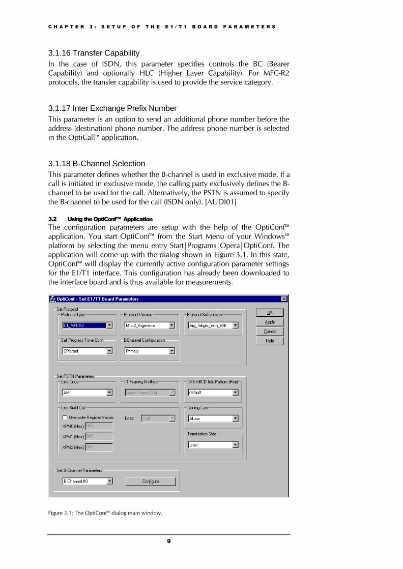
3.2 Using the OptiConf™ ApplicationThe configuration parameters are setup with the help of the OptiConf™application. You start OptiConf™ from the Start Menu of your Windows™platform by selecting the menu entry Start|Programs|Opera|OptiConf. Theapplication will come up with the dialog shown in Figure 3.1. In this state,OptiConf™ will display the currently active configuration parameter settingsfor the E1/T1 interface. This configuration has already been downloaded tothe interface board and is thus available for measurements.
Figure 3.1: The OptiConf™ dialog main window.

C H A P T E R 3 : S E T U P O F T H E E 1 / T 1 B O A R D P A R A M E T E R S
10
If these settings do not meet your requirements, you may change them. In afirst step you might for example select an entry from the Protocol Typecontrol listbox field. After having done so, the corresponding parametervalues will be set in the other parameter fields of the OptiConf™ dialog. Ifnecessary, you may modify one or more parameters now. This is done byeither selecting an entry from the listbox field of a control or by directlyentering the necessary value in an edit field where possible.
Some parameter fields are shown in grey colour and thus may not bemodified. These disabled configuration parameters are either not relevant forthe protocol chosen, or there is only one valid value.
After you will have finished setting all the necessary parameter values, youmay start the initialization process by either clicking on the OK or the Applybutton. After having done so, a message dialog comes up that informs youthat the download process might take up to approx. 2 minutes. Please note,that the initialization process is started only after you have confirmed themessage by clicking on the OK button. The application will then downloadthe configuration set to the E1/T1 interface board.
Note:
Start OptiCall™ only after the initialization process isfinished. Only then the chosen E1/T1 configuration isavailable to perform measurements.
In the following the parameter fields and its valid values are described. Formore detailed information about the parameters, refer to the overview inSection 3.1.
3.2.1 The Parameter Field “Protocol Type”Here you select the name of the protocol type. After choosing a protocolfrom the list, the corresponding default parameter values will be assigned tothe parameter fields in the OptiConf™ dialog. For some protocol types, thereare variants available that may represent country specific variants, forinstance. These variants are available in the Protocol Version and ProtocolSubversion control fields.
3.2.2 The Parameter Field “Protocol Version”This control offers a set of protocol variants that are available for someprotocol types. If there are no variants available, the control will show “Notavailable”.
3.2.3 The Parameter Field “Protocol Subversion”Some protocol types provide another subset of variants which are availablefrom this control field. For example, the MFC-R2 protocol provides variantsfor several countries in the Protocol Version field, and a subset of differentprotocol variants for the chosen country in the Subversion control.
C H A P T E R 3 : S E T U P O F T H E E 1 / T 1 B O A R D P A R A M E T E R S
11
3.2.4 The Parameter Field “Call Progress Tones Conf.”Selects the call progress tones configurations file. If no call progress tonesare to be used the correct entry is “No call progress support”.
3.2.5 The Parameter Field “DChannel Configuration”The D-channel configuration can be set to Primary, NFAS or Backup.
3.2.6 The Parameter Field “Line Code”Specifies the line code type. Select AMI or HDB3 for E1 protocols and AMIor B8ZS for a T1 network.
3.2.7 The Parameter Field “T1 Framing Method”This parameter is applicable for T1 protocol types only. It is used to select“Super Frame (D4)” (12 frames multi-frame - SF) or “Extended Super Frame”(24 frames multi-frame - ESF) for T1.
3.2.8 The Parameter Field “CAS ABCD Idle Pattern”When defining the Idle Pattern, you may choose between an entry in the listfield of the controls or you may enter a value in the control’s edit field.Please note, that the entered value needs to be a hexadecimal number. Youmay enter the value including the prefix “0x” or without it. In both casesyour entry will be interpreted as a hex value. Valid entries are in the rangebetween 0x0 - 0xf.
For example, if you want to specify a pattern ABCD=1010, you have toenter the corresponding hex value which is 0xa.
3.2.9 The Parameter Field “Coding Law”This control selects the coding law that is used on the PC internal TDM bus.Available values are Mu-Law and A-Law. The coding law must match thecoding law of the speech file that is send through a system under test. Pleasenote, that this parameter does not refer to the telephone line coding law.
3.2.10 The Parameter Field “Line Build Out ”The Line Build Out Loss parameter can be set to 0 dB, -7.5 dB, -15 dB, or -22.5 dB. This parameter is disabled in the case of E1 protocols.
The Overwrite parameter may be switched on by by enabling the checkbox.Then, you may define the values for the 3 Pulse Mask (XPM) registers. Pleasenote, that these values have to be entered in hexadecimal data format only.As in the CAS ABCD Idle Pattern field, you may enter the value includingthe prefix “0x” or without it. In both cases your entry will be interpreted as ahex value. The Overwrite parameter is applicable to E1 and T1 protocols.
C H A P T E R 3 : S E T U P O F T H E E 1 / T 1 B O A R D P A R A M E T E R S
12
3.2.11 The Parameter Field “Termination Side”Some protocols are not symmetrical, that is, the user and the network side ofthe protocol are different. In the Termination Side control field you maychange whether your OPERA host computer shall be configured as the userside or the network side of a protocol.
3.2.12 The Parameter Field "Set B-Channel Parameters"For some protocol types, like ISDN or MFC-R2, the parameters for the B-channels need to be set.. In this field you may select from the drop-down listthe B-channel you want to configure. After clicking on the "Configure"button, the dialog for the B-channel configuration will come up as shown inFigure 3.2.
Please note, that only those channels are shown in the list that may carryvoice information. That is, for instance, the D-channel of an ISDNconfigured trunk will not be found in the B-channel list. The numbering ofthe B-channels starts with zero.
Note:
Currently only identical configuration setups of Trunk 1 andTrunk 2 are possible. This is about to change in futureversions of the E1/T1 option.
3.3 Setting up B-Channel Configuration ParametersSections 3.1.9 to 3.1.16 describe a number of parameters that are to be setfor each single B-channel of a trunk. Most of these channel configurationparameters are applicable for ISDN. Only some might be applicable forMFC-R2 protocols, too, which are Source Phone Number, Source PhoneSubnumber, Source Number Type and Transfer Capability.
For modifying B-channel parameter settings, choose the B-channel that yourchanges shall apply to in the main dialog of OptiConf™. When pressing the"Configure" button the dialog shown in Figure 3.2 will come up. Here, youwill see the current settings of the selected B-channel. The parameter valuesfor each B-channels are set separately, and modifying them for one specificB-channel will not affect the settings of another B-channel.
You may also configure all available B-Channels in one step by selecting theentry “All Channels” from the drop-down list in the “Set B-ChannelParameters” field of the main dialog.
In the following, an overview of the B-channel parameters is given.

C H A P T E R 3 : S E T U P O F T H E E 1 / T 1 B O A R D P A R A M E T E R S
13
Figure 3.2: The B-Channel Configuration dialog window.
Note:
Please recall, when changing the channel configuration, yourchanges will only be available after you have re-initialized theE1/T1 board.
Note:
Currently, only channel configuration settings for Trunk #0are supported. That is, that the channel configurations of thesecond trunk will be the same as for the first trunk of theinterface board. . This is about to change in future versions ofthe E1/T1 option.
Destination Numbering Type- Table 3.2 gives an overview of the values forthe parameter Destination Numbering Type.
Not IncludedUnknown NumberInternational NumberNational NumberNetwork Specific Number
C H A P T E R 3 : S E T U P O F T H E E 1 / T 1 B O A R D P A R A M E T E R S
14
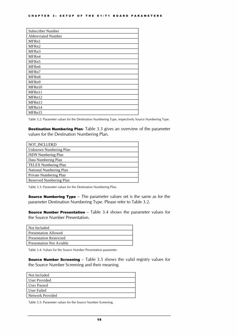
Subscriber NumberAbbreviated NumberMFRn1MFRn2MFRn3MFRn4MFRn5MFRn6MFRn7MFRn8MFRn9MFRn10MFRn11MFRn12MFRn13MFRn14MFRn15
Table 3.2: Parameter values for the Destination Numbering Type, respectively Source Numbering Type.
Destination Numbering Plan- Table 3.3 gives an overview of the parametervalues for the Destination Numbering Plan.
NOT_INCLUDEDUnknown Numbering PlanISDN Numbering PlanData Numbering PlanTELEX Numbering PlanNational Numbering PlanPrivate Numbering PlanReserved Numbering Plan
Table 3.3: Parameter values for the Destination Numbering Plan.
Source Numbering Type – The parameter values set is the same as for theparameter Destination Numbering Type. Please refer to Table 3.2.
Source Number Presentation – Table 3.4 shows the parameter values forthe Source Number Presentation.
Not IncludedPresentation AllowedPresentation RestrictedPresentation Not Aviable
Table 3.4: Values for the Source Number Presentation parameter.
Source Number Screening – Table 3.5 shows the valid registry values forthe Source Number Screening and their meaning.
Not IncludedUser ProvidedUser PassedUser FailedNetwork Provided
Table 3.5: Parameter values for the Source Number Screening.
C H A P T E R 3 : S E T U P O F T H E E 1 / T 1 B O A R D P A R A M E T E R S
15
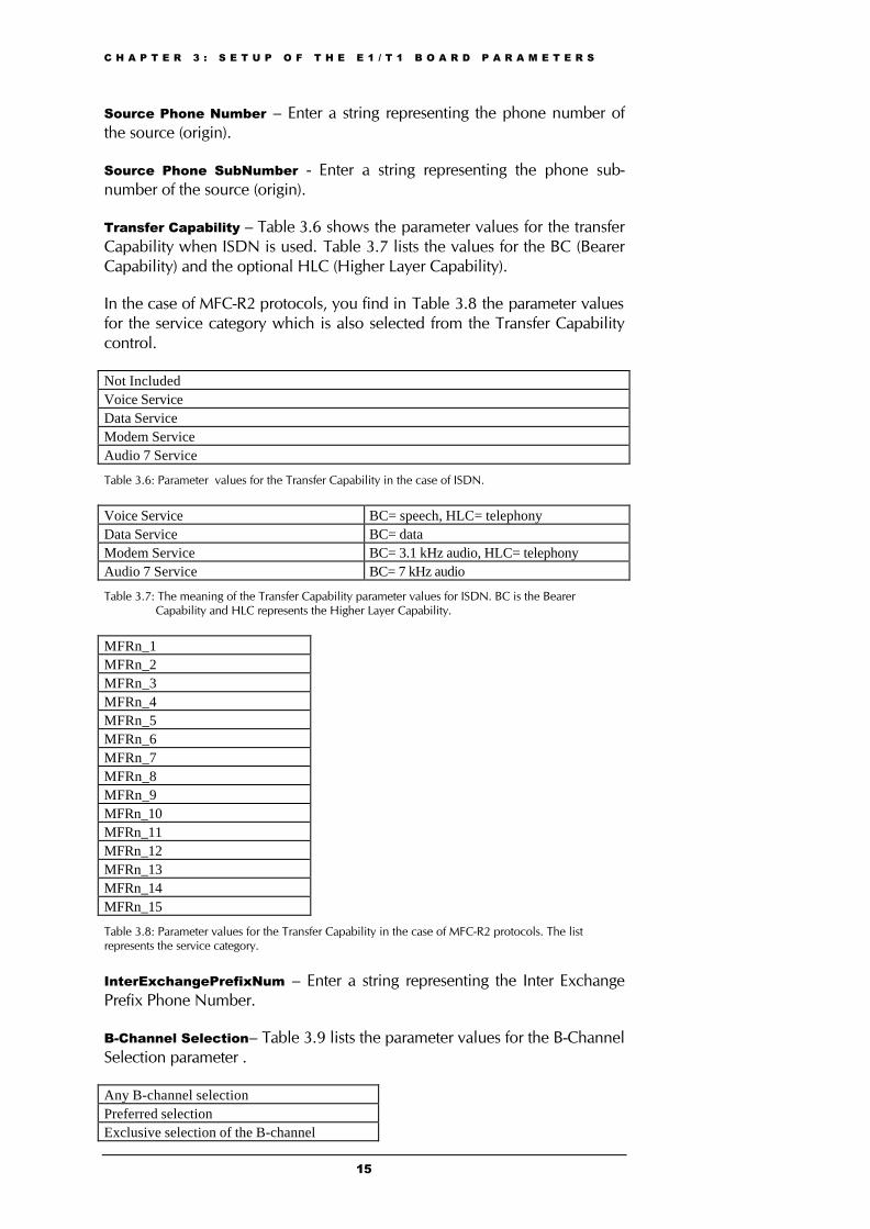
Source Phone Number – Enter a string representing the phone number ofthe source (origin).
Source Phone SubNumber - Enter a string representing the phone sub-number of the source (origin).
Transfer Capability – Table 3.6 shows the parameter values for the transferCapability when ISDN is used. Table 3.7 lists the values for the BC (BearerCapability) and the optional HLC (Higher Layer Capability).
In the case of MFC-R2 protocols, you find in Table 3.8 the parameter valuesfor the service category which is also selected from the Transfer Capabilitycontrol.
Not IncludedVoice ServiceData ServiceModem ServiceAudio 7 Service
Table 3.6: Parameter values for the Transfer Capability in the case of ISDN.
Voice Service BC= speech, HLC= telephonyData Service BC= dataModem Service BC= 3.1 kHz audio, HLC= telephonyAudio 7 Service BC= 7 kHz audio
Table 3.7: The meaning of the Transfer Capability parameter values for ISDN. BC is the BearerCapability and HLC represents the Higher Layer Capability.
MFRn_1MFRn_2MFRn_3MFRn_4MFRn_5MFRn_6MFRn_7MFRn_8MFRn_9MFRn_10MFRn_11MFRn_12MFRn_13MFRn_14MFRn_15
Table 3.8: Parameter values for the Transfer Capability in the case of MFC-R2 protocols. The listrepresents the service category.
InterExchangePrefixNum – Enter a string representing the Inter ExchangePrefix Phone Number.
B-Channel Selection– Table 3.9 lists the parameter values for the B-ChannelSelection parameter .
Any B-channel selectionPreferred selectionExclusive selection of the B-channel

C H A P T E R 3 : S E T U P O F T H E E 1 / T 1 B O A R D P A R A M E T E R S
16
Table 3.9: Parameter values for the Exclusive and their meaning.

C H A P T E R 4 : S I G N A L A C Q U I S I T I O N U S I N G O P T I C A L L ™
17
4 Signal Acquisition Using OptiCall™This section provides a short description of how to use the OptiCall™application to perform measurements using the E1/T1 interfaces. For a moredetailed explanation, please refer to Section 4.2.3 (page 39) in the OPERA™User Manual Version 3.0.
If you are already familiar with using OptiCall™ with POTS telephony oraudio interfaces, you will not face any need for reorientation whenperforming measurements with the E1/T1 interface option. There are only afew things you need to notice which are explained in the following.
Figure 4.1: The OptiCall™ dialog showing selected E1 MFC-R2 interface devices.
As shown in the example screen shot of OptiCall™ in Figure 4.1, theprotocol type you have selected within OptiConf™ (see Section 3.2), isshown as a part of the device name in the list box for the origin andtermination device, respectively. The protocol name is then followed by theport number that represents the index of a trunk of the E1/T1 interface board.For instance, “Port 0” represents the first trunk.
Each E1/T1 device name is terminated by the B-channel notation – e.g. “BCh0” would represent the first valid voice bearing channel of a particular trunk.Please note, that only those channels of a trunk are registered in the devicelist that may carry voice information. That is, the D-channel of an ISDNconfigured trunk will not be found in the device list of OptiCall™, forinstance. Consequently, all E1/T1 entries found in the list boxes of OptiCall™may be used for measuring. The numbering of those channels starts withzero.

C H A P T E R 4 : S I G N A L A C Q U I S I T I O N U S I N G O P T I C A L L ™
18
Note:
The DDLC™ mechanism that compensates for latencies ofthe Windows NT operating system is not available for thecurrent version of the E1/T1 interface option. This may resultin a lower accuracy when measuring the delay of signals.However, this restriction is about to change in future versions.
C H A P T E R 5 : O P T I C A L L ™ C O M M A N D L I N E P A R A M E T E R S
19
5 OptiCall™ Command Line ParametersThis section describes the new features for the automated execution use ofOptiCall™ from scripts. For more detailed explanation of the functionality ofthe command line parameters, refer to page 46 in Section 4.2.3 in theOPERA User Manual Version 3.0.
Note:
The command line parameters described in this sectioncorrespond with the OptiCall™ application but not withOptiConf™. Please remind that you have to configure theE1/T1 interface board using the OptiConf™ dialog beforeusing the automated execution option.
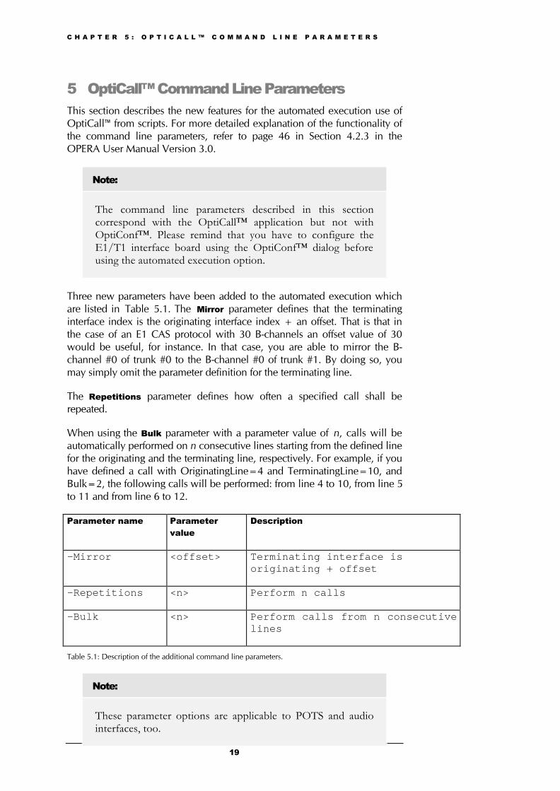
Three new parameters have been added to the automated execution whichare listed in Table 5.1. The Mirror parameter defines that the terminatinginterface index is the originating interface index + an offset. That is that inthe case of an E1 CAS protocol with 30 B-channels an offset value of 30would be useful, for instance. In that case, you are able to mirror the B-channel #0 of trunk #0 to the B-channel #0 of trunk #1. By doing so, youmay simply omit the parameter definition for the terminating line.
The Repetitions parameter defines how often a specified call shall berepeated.
When using the Bulk parameter with a parameter value of n, calls will beautomatically performed on n consecutive lines starting from the defined linefor the originating and the terminating line, respectively. For example, if youhave defined a call with OriginatingLine=4 and TerminatingLine=10, andBulk=2, the following calls will be performed: from line 4 to 10, from line 5to 11 and from line 6 to 12.
Parameter name Parametervalue
Description
-Mirror <offset> Terminating interface isoriginating + offset
-Repetitions <n> Perform n calls
-Bulk <n> Perform calls from n consecutivelines
Table 5.1: Description of the additional command line parameters.
Note:
These parameter options are applicable to POTS and audiointerfaces, too.

C H A P T E R 5 : O P T I C A L L ™ C O M M A N D L I N E P A R A M E T E R S
20
C H A P T E R 6 : M E A S U R E M E N T E X A M P L E S
21
6 Measurement ExamplesThis chapter will be helpful if you are not yet familiar with the OPERA™E1/T1 option. The first section provides some example parameter settings forall protocol types available. Section 6.2 demonstrates a typical loopmeasurement using OptiCall™, while 6.3 will show a typical application ofan automated measurement using a script file. Both examples put theemphasis on the signal acquisition. If you are looking for examples of howto use the OPERA™ analyzer, please refer to the OPERA™ user manual.
6.1 Example Parameter Settings for Several Protocol TypesIn the following, a number of tables containing parameter configurations arelisted. These tables represent example settings for all protocol typesavailable, except for the transparent protocol types. The parameterconfiguration is divided into two sets, the trunk parameters and the B-channel parameters. In the case of those protocol types that do not supportany B-channel parameters, you may simply omit the configuration of thoseparameters. Some of the supported protocols are not symmetrical, that is,that the user and the network side of the protocol are different. The relevantconfiguration field is “Termination Side”. Please note, that currently onlyidentical configurations for all trunks of a board are supported. As aconsequence, it is currently not possible to configure one trunk as the userside and the other as the network side of the protocol.
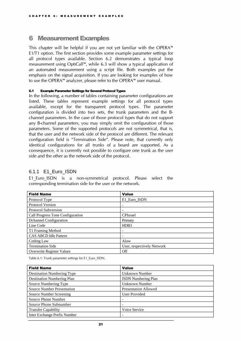
6.1.1 E1_Euro_ISDNE1_Euro_ISDN is a non-symmetrical protocol. Please select thecorresponding termination side for the user or the network.
Field Name ValueProtocol Type E1_Euro_ISDNProtocol Version -Protocol Subversion -Call Progress Tone Configuration CPIsraelDchannel Configuration PrimaryLine Code HDB3T1 Framing Method -CAS ABCD Idle Pattern -Coding Law AlawTermination Side User, respectively NetworkOverwrite Register Values Off
Table 6.1: Trunk parameter settings for E1_Euro_ISDN.
Field Name ValueDestination Numbering Type Unknown NumberDestination Numbering Plan ISDN Numbering PlanSource Numbering Type Unknown NumberSource Number Presentation Presentation AllowedSource Number Screening User ProvidedSource Phone Number -Source Phone Subnumber -Transfer Capability Voice ServiceInter Exchange Prefix Number -
C H A P T E R 6 : M E A S U R E M E N T E X A M P L E S
22
B-Channel Selection Exclusive Selection
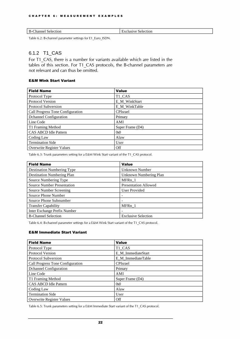
Table 6.2: B-channel parameter settings for E1_Euro_ISDN.
6.1.2 T1_CASFor T1_CAS, there is a number for variants available which are listed in thetables of this section. For T1_CAS protocols, the B-channel parameters arenot relevant and can thus be omitted.
E&M Wink Start Variant
Field Name ValueProtocol Type T1_CASProtocol Version E_M_WinkStartProtocol Subversion E_M_WinkTableCall Progress Tone Configuration CPIsraelDchannel Configuration PrimaryLine Code AMIT1 Framing Method Super Frame (D4)CAS ABCD Idle Pattern 0x0Coding Law AlawTermination Side UserOverwrite Register Values Off
Table 6.3: Trunk parameters setting for a E&M Wink Start variant of the T1_CAS protocol.
Field Name ValueDestination Numbering Type Unknown NumberDestination Numbering Plan Unknown Numbering PlanSource Numbering Type MFRn_1Source Number Presentation Presentation AllowedSource Number Screening User ProvidedSource Phone Number -Source Phone Subnumber -Transfer Capability MFRn_1Inter Exchange Prefix Number -B-Channel Selection Exclusive Selection
Table 6.4: B-channel parameter settings for a E&M Wink Start variant of the T1_CAS protocol.
E&M Immediate Start Variant
Field Name ValueProtocol Type T1_CASProtocol Version E_M_ImmediateStartProtocol Subversion E_M_ImmediateTableCall Progress Tone Configuration CPIsraelDchannel Configuration PrimaryLine Code AMIT1 Framing Method Super Frame (D4)CAS ABCD Idle Pattern 0x0Coding Law AlawTermination Side UserOverwrite Register Values Off
Table 6.5: Trunk parameters setting for a E&M Immediate Start variant of the T1_CAS protocol.
C H A P T E R 6 : M E A S U R E M E N T E X A M P L E S
23
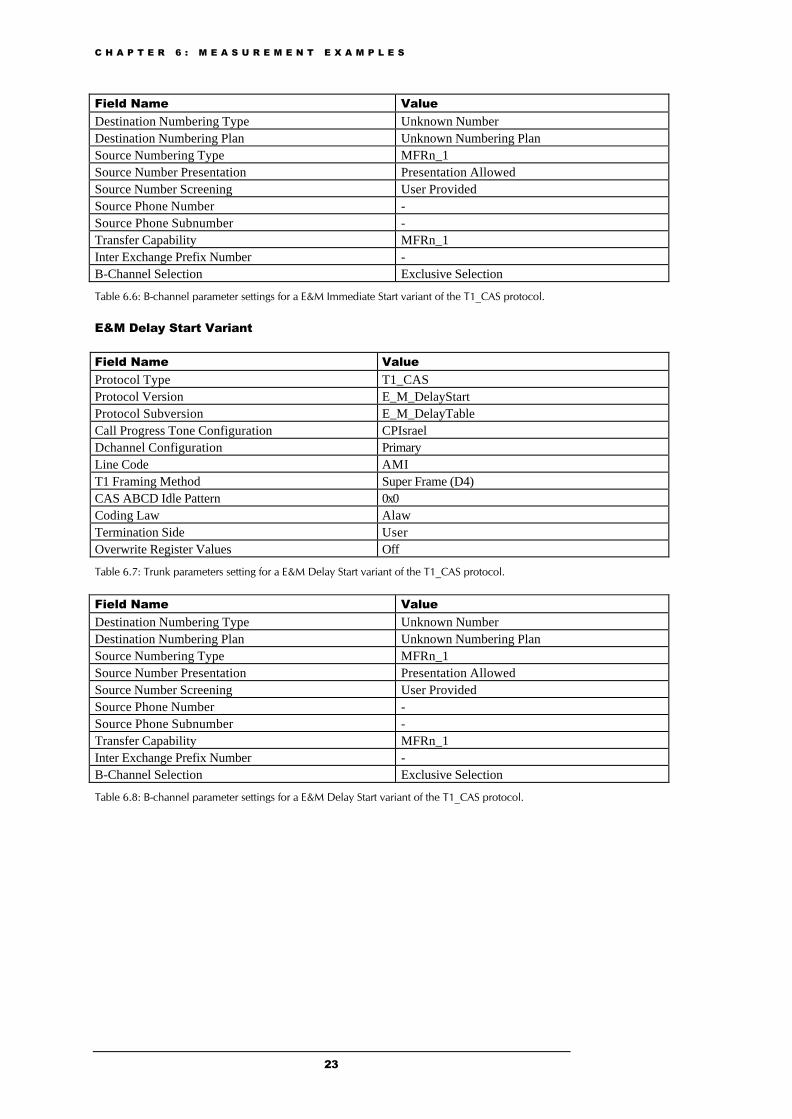
Field Name ValueDestination Numbering Type Unknown NumberDestination Numbering Plan Unknown Numbering PlanSource Numbering Type MFRn_1Source Number Presentation Presentation AllowedSource Number Screening User ProvidedSource Phone Number -Source Phone Subnumber -Transfer Capability MFRn_1Inter Exchange Prefix Number -B-Channel Selection Exclusive Selection
Table 6.6: B-channel parameter settings for a E&M Immediate Start variant of the T1_CAS protocol.
E&M Delay Start Variant
Field Name ValueProtocol Type T1_CASProtocol Version E_M_DelayStartProtocol Subversion E_M_DelayTableCall Progress Tone Configuration CPIsraelDchannel Configuration PrimaryLine Code AMIT1 Framing Method Super Frame (D4)CAS ABCD Idle Pattern 0x0Coding Law AlawTermination Side UserOverwrite Register Values Off
Table 6.7: Trunk parameters setting for a E&M Delay Start variant of the T1_CAS protocol.
Field Name ValueDestination Numbering Type Unknown NumberDestination Numbering Plan Unknown Numbering PlanSource Numbering Type MFRn_1Source Number Presentation Presentation AllowedSource Number Screening User ProvidedSource Phone Number -Source Phone Subnumber -Transfer Capability MFRn_1Inter Exchange Prefix Number -B-Channel Selection Exclusive Selection
Table 6.8: B-channel parameter settings for a E&M Delay Start variant of the T1_CAS protocol.
C H A P T E R 6 : M E A S U R E M E N T E X A M P L E S
24
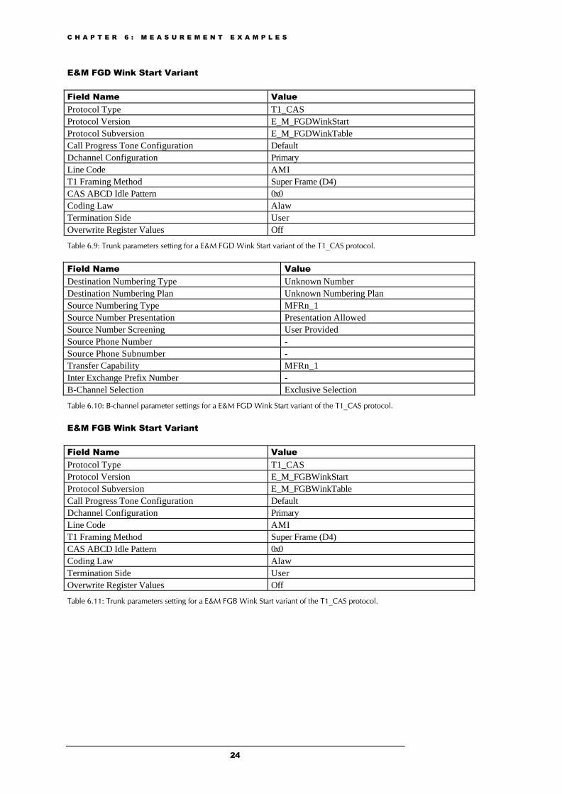
E&M FGD Wink Start Variant
Field Name ValueProtocol Type T1_CASProtocol Version E_M_FGDWinkStartProtocol Subversion E_M_FGDWinkTableCall Progress Tone Configuration DefaultDchannel Configuration PrimaryLine Code AMIT1 Framing Method Super Frame (D4)CAS ABCD Idle Pattern 0x0Coding Law AlawTermination Side UserOverwrite Register Values Off
Table 6.9: Trunk parameters setting for a E&M FGD Wink Start variant of the T1_CAS protocol.
Field Name ValueDestination Numbering Type Unknown NumberDestination Numbering Plan Unknown Numbering PlanSource Numbering Type MFRn_1Source Number Presentation Presentation AllowedSource Number Screening User ProvidedSource Phone Number -Source Phone Subnumber -Transfer Capability MFRn_1Inter Exchange Prefix Number -B-Channel Selection Exclusive Selection
Table 6.10: B-channel parameter settings for a E&M FGD Wink Start variant of the T1_CAS protocol.
E&M FGB Wink Start Variant
Field Name ValueProtocol Type T1_CASProtocol Version E_M_FGBWinkStartProtocol Subversion E_M_FGBWinkTableCall Progress Tone Configuration DefaultDchannel Configuration PrimaryLine Code AMIT1 Framing Method Super Frame (D4)CAS ABCD Idle Pattern 0x0Coding Law AlawTermination Side UserOverwrite Register Values Off
Table 6.11: Trunk parameters setting for a E&M FGB Wink Start variant of the T1_CAS protocol.
C H A P T E R 6 : M E A S U R E M E N T E X A M P L E S
25
Field Name ValueDestination Numbering Type Unknown NumberDestination Numbering Plan Unknown Numbering PlanSource Numbering Type MFRn_1Source Number Presentation Presentation AllowedSource Number Screening User ProvidedSource Phone Number -Source Phone Subnumber -Transfer Capability MFRn_1Inter Exchange Prefix Number -B-Channel Selection Exclusive Selection
Table 6.12: B-channel parameter settings for a E&M FGB Wink Start variant of the T1_CAS protocol.
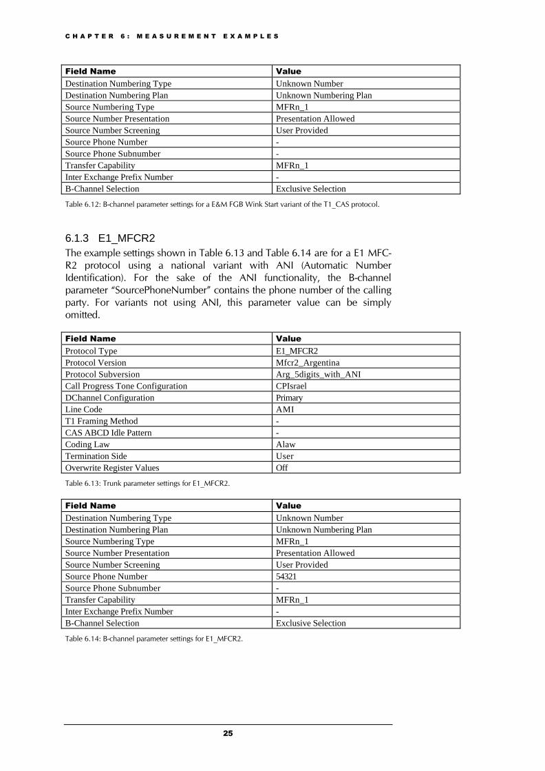
6.1.3 E1_MFCR2The example settings shown in Table 6.13 and Table 6.14 are for a E1 MFC-R2 protocol using a national variant with ANI (Automatic NumberIdentification). For the sake of the ANI functionality, the B-channelparameter “SourcePhoneNumber” contains the phone number of the callingparty. For variants not using ANI, this parameter value can be simplyomitted.
Field Name ValueProtocol Type E1_MFCR2Protocol Version Mfcr2_ArgentinaProtocol Subversion Arg_5digits_with_ANICall Progress Tone Configuration CPIsraelDChannel Configuration PrimaryLine Code AMIT1 Framing Method -CAS ABCD Idle Pattern -Coding Law AlawTermination Side UserOverwrite Register Values Off
Table 6.13: Trunk parameter settings for E1_MFCR2.
Field Name ValueDestination Numbering Type Unknown NumberDestination Numbering Plan Unknown Numbering PlanSource Numbering Type MFRn_1Source Number Presentation Presentation AllowedSource Number Screening User ProvidedSource Phone Number 54321Source Phone Subnumber -Transfer Capability MFRn_1Inter Exchange Prefix Number -B-Channel Selection Exclusive Selection
Table 6.14: B-channel parameter settings for E1_MFCR2.

C H A P T E R 6 : M E A S U R E M E N T E X A M P L E S
26
6.1.4 E1_CAS_R2Field Name ValueProtocol Type E1_CAS_R2Protocol Version E1_R2DProtocol Subversion E1_R2DCall Progress Tone Configuration CPIsraelDchannel Configuration PrimaryLine Code AMIT1 Framing Method -CAS ABCD Idle Pattern -Coding Law AlawTermination Side UserOverwrite Register Values Off
Table 6.15: Trunk parameter settings for E1_CAS_R2.
Field Name ValueDestination Numbering Type Unknown NumberDestination Numbering Plan Unknown Numbering PlanSource Numbering Type MFRn_1Source Number Presentation Presentation AllowedSource Number Screening User ProvidedSource Phone Number -Source Phone Subnumber -Transfer Capability MFRn_1Inter Exchange Prefix Number -B-Channel Selection Exclusive Selection
Table 6.16: B-channel parameter settings for E1_CAS_R2.
6.1.5 T1_NI2_ISDNT1_NI2_ISDN is a non-symmetrical protocol. Please select thecorresponding termination side for the user or the network.
Field Name ValueProtocol Type T1_NI2_ISDNProtocol Version -Protocol Subversion -Call Progress Tone Configuration CPIsraelDchannel Configuration PrimaryLine Code B8ZST1 Framing Method Extended Super FrameCAS ABCD Idle Pattern -Coding Law AlawTermination Side User, respectively NetworkOverwrite Register Values Off
Table 6.17: Trunk parameter settings for T1_NI2_ISDN.

C H A P T E R 6 : M E A S U R E M E N T E X A M P L E S
27
Field Name ValueDestination Numbering Type National NumberDestination Numbering Plan ISDN Numbering PlanSource Numbering Type National NumberSource Number Presentation Presentation AllowedSource Number Screening User ProvidedSource Phone Number -Source Phone Subnumber -Transfer Capability Voice ServiceInter Exchange Prefix Number -B-Channel Selection Exclusive Selection
Table 6.18: B-channel parameter settings for T1_NI2_ISDN.

C H A P T E R 6 : M E A S U R E M E N T E X A M P L E S
28
6.1.6 T1_5ESS_10_ISDNT1_5ESS_10_ISDN is a non-symmetrical protocol. Please select thecorresponding termination side for the user or the network.
Field Name ValueProtocol Type T1_5ESS_10_ISDNProtocol Version -Protocol Subversion -Call Progress Tone Configuration CPIsraelDchannel Configuration PrimaryLine Code B8ZST1 Framing Method Extended Super FrameCAS ABCD Idle Pattern -Coding Law AlawTermination Side User, respectively NetworkOverwrite Register Values Off
Table 6.19: Trunk parameter settings for T1_5ESS_10_ISDN.
Field Name ValueDestination Numbering Type National NumberDestination Numbering Plan ISDN Numbering PlanSource Numbering Type National NumberSource Number Presentation Presentation AllowedSource Number Screening User ProvidedSource Phone Number -Source Phone Subnumber -Transfer Capability Voice ServiceInter Exchange Prefix Number -B-Channel Selection Exclusive Selection
Table 6.20: B-channel parameter settings for T1_5ESS_10_ISDN.
6.1.7 T1_DMS100_ISDNT1_DMS100_ISDN is a non-symmetrical protocol. Please select thecorresponding termination side for the user or the network.
Field Name ValueProtocol Type T1_DMS100_ISDNProtocol Version -Protocol Subversion -Call Progress Tone Configuration CPIsraelDchannel Configuration PrimaryLine Code B8ZST1 Framing Method Extended Super FrameCAS ABCD Idle Pattern -Coding Law AlawTermination Side User, respectively NetworkOverwrite Register Values Off
Table 6.21: Trunk parameter settings for T1_DMS100_ISDN.

C H A P T E R 6 : M E A S U R E M E N T E X A M P L E S
29
Field Name ValueDestination Numbering Type National NumberDestination Numbering Plan ISDN Numbering PlanSource Numbering Type National NumberSource Number Presentation Presentation AllowedSource Number Screening User ProvidedSource Phone Number -Source Phone Subnumber -Transfer Capability Voice ServiceInter Exchange Prefix Number -B-Channel Selection Exclusive Selection
Table 6.22: B-channel parameter settings for T1_DMS100_ISDN.
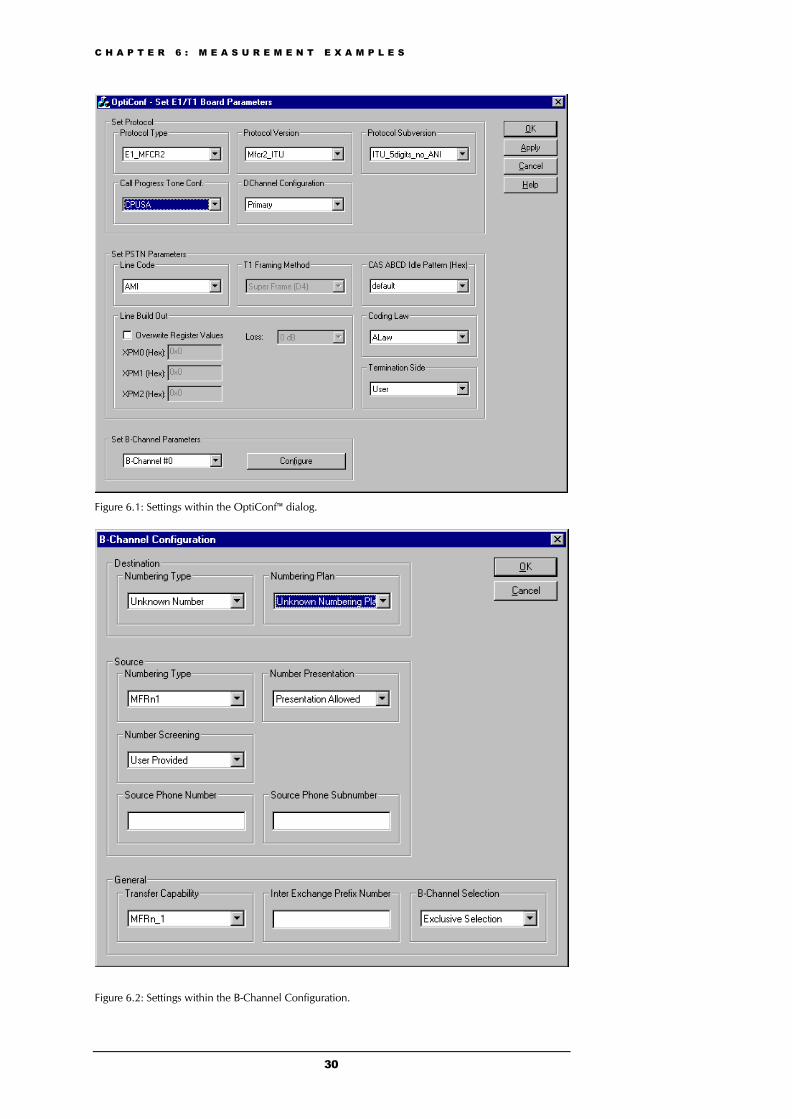
6.2 Example 1: Stand Alone Loop MeasurementFirst of all, in order to perform a loop call, you will have to take care that thetelephone line is looped back on the far end, so you will get your signal tothe terminating line. After having connected both trunks of the E1/T1interface board to the SUT, start the board parameter configurator bychoosing the menu Start|Programs|Opera|OptiConf. In the dialog ofOptiConf™, we select the protocol type “E1_MFCR2” as shown in Figure6.1. The protocol version “Mfcr2_ITU” is chosen with a subversion using 5digits without ANI function.
We will run a measurement from B-channel 0 with OptiCall™. For this B-channel, the parameter settings as shown in Figure 6.2 are selected withinthe B-channel configuration dialog. Confirm the B-channel configurationwith the OK button.
All the other parameter values in the main dialog of OptiConf™ are assumedto be fine in our example. We leave them as they are and start theinitialization process by clicking on the Apply button.
C H A P T E R 6 : M E A S U R E M E N T E X A M P L E S
30
Figure 6.1: Settings within the OptiConf™ dialog.
Figure 6.2: Settings within the B-Channel Configuration.
C H A P T E R 6 : M E A S U R E M E N T E X A M P L E S
31
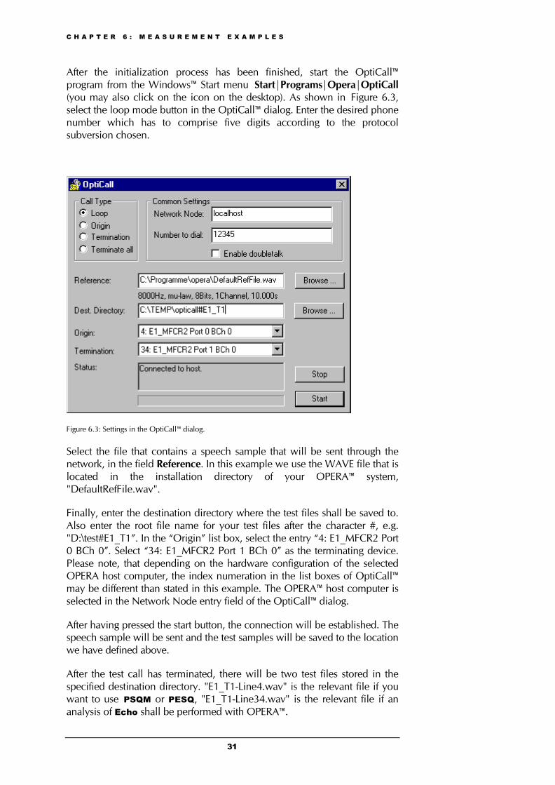
After the initialization process has been finished, start the OptiCall™program from the Windows™ Start menu Start|Programs|Opera|OptiCall(you may also click on the icon on the desktop). As shown in Figure 6.3,select the loop mode button in the OptiCall™ dialog. Enter the desired phonenumber which has to comprise five digits according to the protocolsubversion chosen.
Figure 6.3: Settings in the OptiCall™ dialog.
Select the file that contains a speech sample that will be sent through thenetwork, in the field Reference. In this example we use the WAVE file that islocated in the installation directory of your OPERA™ system,"DefaultRefFile.wav".
Finally, enter the destination directory where the test files shall be saved to.Also enter the root file name for your test files after the character #, e.g."D:\test#E1_T1”. In the “Origin” list box, select the entry “4: E1_MFCR2 Port0 BCh 0”. Select “34: E1_MFCR2 Port 1 BCh 0” as the terminating device.Please note, that depending on the hardware configuration of the selectedOPERA host computer, the index numeration in the list boxes of OptiCall™may be different than stated in this example. The OPERA™ host computer isselected in the Network Node entry field of the OptiCall™ dialog.
After having pressed the start button, the connection will be established. Thespeech sample will be sent and the test samples will be saved to the locationwe have defined above.
After the test call has terminated, there will be two test files stored in thespecified destination directory. "E1_T1-Line4.wav" is the relevant file if youwant to use PSQM or PESQ, "E1_T1-Line34.wav" is the relevant file if ananalysis of Echo shall be performed with OPERA™.
C H A P T E R 6 : M E A S U R E M E N T E X A M P L E S
32
6.3 Example 2: Measurements From a Batch FileThis example describes only the command line functionality to acquire thesignals with a system under test. For an example of how to use thecommand line option to analyze files, please refer to the OPERA™ usermanual.
Again, you will have to take care that the telephone line is looped back onthe far end, so you will get your signal to the terminating line. Connect bothtrunks of the E1/T1 interface board to the SUT. As described in the examplein 6.1, we have to configure the E1/T1 interface using the OptiConf™ dialog,before we run the automated measurement from the script file. In OptiConf™™, we select the protocol type “E1_MFCR2”, the protocol version“Mfcr2_ITU” and the subversion using 5 digits without ANI function (seeFigure 6.1). Since all the other parameter values are fine for our example, weleave them as they are and start the initialization process by clicking on theApply button.
Note:
Only run the batch file after you have received the messagethat the initialization process has been finished. Only then theboard configuration is available for the automated execution.
We now want to use the same settings as described in Example 1. We willperform a loop measurement, the number to dial is “12345”, the referencefile is taken from the location “C:\programme\opera\DefaultRefFile.wav”,destination directory is "D:\test#E1_T1”. The originating line index is chosencorresponding to the index number of the device entry “4:E1_MFCR2_ITU_5Digits_no_ANI Port 0 BCh 0” and the terminating lineindex would then be 34. We will use the Mirror parameter to set theterminating line. The correct offset value is then 30 in accordance with thechosen E1 protocol. Thus, the correct command line will be as follows(should be written in one line in the batch file):
Opticall /Exec –Loop –OriginatingLine 4 –Mirror 30 –Phonenumber 12345 –RefFileOrigin
C:\programme\opera\DefaultRefFile.wav –RefFileTerminationC:\programme\opera\DefaultRefFile.wav –DestinationPath D:\test –Root E1_T1
After the batch file has been executed, the resulting files will beD:\test\E1_T1-Line4.wav (to be used for PSQM or PESQ analysis) andD:\test\E1_T1-Line34.wav (for Echo analysis).
C H A P T E R 7 : O P T I O N S F O R A D V A N C E D U S E R S
33
7 Options for Advanced Users7.1 Editing a Call Progress Tones Configuration FileThe Call Progress Tones Configuration File contains the definitions of thecall progress tones to be detected/generated by the board. Users can useeither one of the files supplied by OPTICOMor construct their own file.
The Call Progress Tones Configuration File used for the configuration of theE1/T1 interface board is a binary file (with extension .dat). Users canconstruct their own configuration file by starting with the Windows ini fileformat and then converting it into binary format using the “Downloadableconstruction utility” described in Section 7.4.
The Windows® ini file format contains two sections, [NUMBER OF CALLPROGRESS TONES] and [CALL PROGRESS TONE #X]. A description ofboth of them is given in the following.
[NUMBER OF CALL PROGRESS TONES] Only one key is provided:
• Number of Call Progress Tones - Defines the number of callprogress tones to be defined in the file.
[CALL PROGRESS TONE #X] - Containing the Xth tone definition(starting from 1 and not exceeding the number of call progress tones definedin the first section) using the following keys:
• Tone Type - Call progress tone type as defined in Table 7.1(assign the number and not the enumeration):
Tone Type Number DefinitionCallProgressDialTone 1CallProgressRingingTone 2CallProgressBusyTone 3CallProgressCongestionTone 4CallProgressSpecialInfoTone 5CallProgressWarningTone 6CallProgressReorderTone 7
Table 7.1: Available tone types and assigned number definitions.
• Low Freq [Hz] - Frequency in Hertz of the lower tonecomponent in the case of a dual frequency tone or the frequency ofthe tone in the case of a single tone.
• High Freq [Hz] - Frequency in Hertz of the higher tonecomponent in the case of dual frequency tone or zero (0) in the caseof a single tone.
• Low Freq Level [-dBm] - Generation level in dBm of the lowertone component in the case of a dual frequency tone or thegeneration level of the tone in the case of a single tone.
C H A P T E R 7 : O P T I O N S F O R A D V A N C E D U S E R S
34
• High Freq Level [-dBm] - Generation level in dBm of thehigher tone component in the case of a dual frequency tone, or zero(0) in the case of a single tone.
• First Signal On Time [10 msec] - “Signal On” period (in 10msec units) for the first cadence on-off cycle.
• First Signal Off Time [10 msec] - “Signal Off” period (in 10msec units) for the first cadence on-off cycle.
• Second Signal On Time [10 msec] - “Signal On” period (in 10 msecunits) for the second cadence on-off cycle.
• Second Signal Off Time [10 msec] - “Signal Off” period (in 10 msecunits) for the second cadence on-off cycle.
Using this configuration file, the user can create up to 16 different callprogress tones using up to 15 different frequencies. Each one of the callprogress tones is specified by the following parameters: the tone frequency(either single or dual frequencies are supported) and the tone cadence. Thisis specified by 2 sets of ON/OFF periods, but you may discard the use of thesecond On/Off cycle by setting the relevant parameters to zero. When thetone is made up of single frequency, the second frequency field should beset to zero. [AUDI01]
7.2 Editing a CAS Protocol Table
7.2.1 OverviewCAS/Robbed Bit protocols implement the specific state machine. The usercan change the protocol’s parameters and even the entire state machine viatwo related files: the Protocol Table Text File and the User-definedParameters Header File.
The Protocol Table Text File is describing the protocol state machine andvarious initialization parameters for tuning to a specific switch or PBX. TheProtocol Table Text File is named xxx.txt.
The User-defined Parameters Header File maps the text-named parametersdefined in the above Protocol Table Text File to their User-defined numericalvalues. The User-defined Parameters Header File is namedUserProt_defines_xxx.h.
The Protocol Table/Script File is the file that is being created after theProtocol Table Text File xxx.txt has been compiled. It is the file which isdownloaded to the E1/T1 interface board during the initialization process.The Protocol Table/Script File is named xxx.dat.
After a change has been made, the Protocol Table Text File must be re-compiled and the interface board must be re-initialized in order to downloadthe updated Protocol Table/Script File xxx.dat.
C H A P T E R 7 : O P T I O N S F O R A D V A N C E D U S E R S
35
7.2.2 Constructing or Modifying a CAS Protocol TableThe protocol table text file is a textual file containing the protocol’s statemachine that defines the whole protocol process. It is constructed of States,pre-defined Actions/Events, and pre-defined Functions.
Thus, the user has full control of the CAS protocol by a relatively simpletextual tool. The user is capable of defining or changing any CAS protocol bywriting the protocol state machine in a text file with a few simple rules.
The user procedure to generate the protocol file is as follows:
• Learn the protocol text file rules which are explained in thefollowing sections. Rules detailed in this manual and syntax arebased on C pre-processor commands.
• Get example files provided by Opticom. These files can be found inthe directory ~\E1_T1 Protocols where “~” represents the OPERA™installation directory. For instance, you might want to have a look atthe directory ~\E1_T1 Protocols\T1_CAS\E_M_WinkStart.
• Build the specific protocol table text file (xxx.txt) and its relatednumerical value header file (xxx.h).
• Compile the xxx.txt with the Downloadable Conversion Utility toproduce the xxx.dat file. Refer to Section 7.4 for a detaileddescription of the utility usage.
• Re-initialize the E1/T1 interface using OptiConf™.
7.2.3 Table ElementsThe file CASSetup.h includes all the pre-defined tools needed to build a newprotocol text file or modifying an existing one. The protocol table text file iscomposed of the following elements:
INIT variablesThe user can change the numeric values of INIT variables inUserProt_defines_xxx.h. For example, INIT_RC_IDLE_CAS defines theABCD bits expected to be received in the IDLE state, INIT_DTMF_DIALdefines the on-time and off-time for the DTMF digits generated towards thePSTN. See the detailed list in CASSetup.h and in the sample protocol textfile. Please refer to the ST_INIT detailed explanation below.
ActionsActions (i.e. protocol table events) are protocol table events activated eitherby the DSP (e.g. EV_CAS_01) or by the user (e.g., EV_PLACE_CALL,EV_TIMER_EXPIRED1). The full list of the possible pre-defined events listcan be found in the CASSetup.h file.
C H A P T E R 7 : O P T I O N S F O R A D V A N C E D U S E R S
36
FunctionsThe functions define a certain procedure that can be activated in any state orin the transition from one state to another. The available functions includefor example SET_TIMER (timer number, timeout in ms.) or SEND_CAS (ABvalue, CD value). A full list of the possible pre-defined functions list can befound in the CASSetup.h file.
StatesEach Protocol Table consists of several states that it switches between duringthe call setup and tear down process. Every state definition begins with theprefix ST_ followed by the state name and colons. The body of the state iscomposed of up to 4 unconditional performed functions and list of actionsthat may trigger this state.
As an example, the following was taken from an E&M wink start tableprotocol file. Table 7.2 shows the protocol table elements for the dial stateST_DIAL.
ParameterAction Function
#1 #2 #3
Next State
FUNCTION0 SET_TIMER 2 Extra DelayBefore Dial
None DO
EV_TIMER_EXPIRED2
SEND_DEST_NUM
None None None NO_STATE
EV_DIAL_ENDED
SET_TIMER 4 No Answer Time None ST_DIAL_ENDED
Table 7.2: ST_DIAL: Protocol table elements.
When the state machine reaches the dial state, it sets timer number 2 andthen waits for one of the two possible actions to trigger: either timer 2expiration or end of dial event. When timer 2 expires, the protocol tableexecutes SEND_DEST_NUM function and stays in the same state(NEXT_STATE=NO_STATE). When the dial event ends, the protocol tablesets timer 4 and moves to ST_DIAL_ENDED written in the NEXT_STATEfield.
Although Users can define their own states, there are two states defined inthe CASSetup.h file that must appear in every protocol table created. Thosetwo states are ST_INIT and ST_IDLE which are described in the following.
1) ST_INIT - When channels initialization is selected, the table enters theInit state. This state contains functions that initialize the global parametersdescribed in Table 7.3.
Parameter Description
RC_IDLE_CAS Defines the ABCD bits expected to be received in the IDLE state in the specificprotocol.
TX_IDLE_CAS Defines the ABCD bits transmitted on IDLE state in the specific protocol.
DIAL_PLAN A change regarding the issue of an incoming call dialed number is implemented inrevision 3.21 as opposed to revision 3.2 and earlier. In revision 3.2 and earlier, users
C H A P T E R 7 : O P T I O N S F O R A D V A N C E D U S E R S
37
had to pre-define the expected number of digit to receive an incoming call. If a lowernumber of digits from the expected were received, the call setup would have failed.
Table 7.3: Global parameters for ST_INIT.
The incoming call detection event is processed by declaring the end of digitreception in the following ways (both for ADDRESS/destination number andANI/source number):
• Receiving ‘#’ digit (in MF or DTMF).
• The number of digits collected reaches its max value defined asDIAL_PLAN Parameter #1 and #2 for destination and ANI numbersrespectively.
• A pre-defined time-out value defined as DIAL_PLAN Parameter #3elapses.
Note:
This method is not used when working with MFC-R2protocols. MFC-R2 uses the expected number of digitsdefined in the file UserProt_defines_xxx.h.
• DTMF_DIAL - Defines the on-time and off-time for the DTMF digitsgenerated towards the PSTN.
• COMMA_PAUSE_TIME - Defines the delay between each digitwhen a comma is used as part of the dialed number string.
• DTMF_DETECTION - Defines the min/max On time for DTMFdigit dialing detection.
• PULSE_DIAL_TIME - Not supported by current stack version.Defines the Break and Make time for pulse dialing.
• PULSE_DIAL - Not supported by current stack version. Defines theBreak and Make ABCD bits for pulse dialing.
• DEBOUNCE - Defines the interval time of CAS to be considered asa hit.
• COLLECT_ANI - Enable or Disable reception of ANI in aspecific protocol.
• DIGIT_TYPE - Defines the dialing method used (DTMF, MF). Inthe case of MFC-R2 protocols, this parameter is not applicable (digitsare assumed to be R2 digits).
2) ST_IDLE - When no active call is established or being established, thetable resides in Idle state, allowing it to start the process of incoming or
C H A P T E R 7 : O P T I O N S F O R A D V A N C E D U S E R S
38
outgoing calls. When the call is cleared the state machine table returns to itsidle state.
Reserved wordsReserved words like DO, NO_STATE, etc. are listed in CASSetup.h.
7.2.4 State’s Line StructureEach text line in the body of each state is composed of 6 columns:
• action/event
• function
• parameter #1
• parameter #2
• parameter #3
• next state
These columns are described in the following.
Action/eventThe name of the table’s events which are the possible triggers for the wholeprotocol state machine. Those can be selected from the list of events definedin the CASSetup.h file (e.g. EV_DISCONNECT_INCOMING).
At the beginning of the state, there can be up to 4 special unconditionalaction/events called FUNCTION. These events are functions that areunconditionally performed when the table reaches the state. These actionsare labeled FUNCTION0 to FUNCTION3.
Following is the list of available protocols table actions (events to the statemachine):
1) User command oriented:
EV_PLACE_CALL - when the user places a call.
EV_ANSWER - when the user answers a call.
EV_DISCONNECT_OUTGOING - when the user disconnects acall and the call is outgoing.
EV_DISCONNECT_INCOMING - when the user disconnects a call andthe call is incoming.
EV_RELEASE_CALL - when the user releases a call.
2) CAS change oriented:
C H A P T E R 7 : O P T I O N S F O R A D V A N C E D U S E R S
39
EV_CAS_1_1 - a new CAS A,B bits received (A=1, B=1, wasstable for the bouncing period).
EV_CAS_1_0 - a new CAS A,B bits received (A=1, B=0, wasstable for the bouncing period).
EV_CAS_0_1 - a new CAS A,B bits received (A=0, B=1, wasstable for the bouncing period).
EV_CAS_0_0 - a new CAS A,B bits received (A=0, B=0, wasstable for the bouncing period).
3) Timers oriented:
EV_TIMER_EXPIRED1 - timer 1 that was previously set by table hadexpired.
EV_TIMER_EXPIRED2 - timer 2 that was previously set by table hadexpired.
EV_TIMER_EXPIRED3 - timer 3 that was previously set by table hadexpired.
EV_TIMER_EXPIRED4 - timer 4 that was previously set by table hadexpired.
EV_TIMER_EXPIRED5 - timer 5 that was previously set by table hadexpired.
EV_TIMER_EXPIRED6 - timer 6 that was previously set by table hadexpired.
EV_TIMER_EXPIRED7 - timer 7 that was previously set by table hadexpired.
EV_TIMER_EXPIRED8 - timer 8 that was previously set by table hadexpired.
4) Counters oriented:
EV_COUNTER1_EXPIRED - counter 1 value reached 0.
EV_COUNTER2_EXPIRED - counter 2 value reached 0.
5) IBS oriented:
EV_RB_TONE_STARTED - ring back tone according to its definition inthe call progress ini file (type and index) was detected.
EV_RB_TONE_STOPPED - ring back tone according to its definition inthe call progress ini file (type and index) was stopped after it waspreviously detected.
6) MF oriented (MFC-R2 protocol related):

C H A P T E R 7 : O P T I O N S F O R A D V A N C E D U S E R S
40
EV_MFRn_1 - MF digit 1 detected.
EV_MFRn_2 - MF digit 2 detected.
EV_MFRn_3 - MF digit 3 detected.
EV_MFRn_4 - MF digit 4 detected.
EV_MFRn_5 - MF digit 5 detected.
EV_MFRn_6 - MF digit 6 detected.
EV_MFRn_7 - MF digit 7 detected.
EV_MFRn_8 - MF digit 8 detected.
EV_MFRn_9 - MF digit 9 detected.
EV_MFRn_10 - MF digit 10 detected.
EV_MFRn_11 - MF digit 11 detected.
EV_MFRn_12 - MF digit 12 detected.
EV_MFRn_13 - MF digit 13 detected.
EV_MFRn_14 - MF digit 14 detected.
EV_MFRn_15 - MF digit 15 detected.
EV_MFRn_1_STOPPED - MF digit 1 previously detected, nowstopped.
EV_MFRn_2_ STOPPED - MF digit 2 previously detected, nowstopped.
EV_MFRn_3_ STOPPED - MF digit 3 previously detected, nowstopped.
EV_MFRn_4_ STOPPED - MF digit 4 previously detected, nowstopped.
EV_MFRn_5_ STOPPED - MF digit 5 previously detected, nowstopped.
EV_MFRn_6_ STOPPED - MF digit 6 previously detected, nowstopped.
EV_MFRn_7_ STOPPED - MF digit 7 previously detected, nowstopped.
EV_MFRn_8_ STOPPED - MF digit 8 previously detected, nowstopped.
C H A P T E R 7 : O P T I O N S F O R A D V A N C E D U S E R S
41
EV_MFRn_9_ STOPPED - MF digit 9 previously detected, nowstopped.
EV_MFRn_10_ STOPPED - MF digit 10 previously detected, nowstopped.
EV_MFRn_11_ STOPPED - MF digit 11 previously detected, nowstopped.
EV_MFRn_12_ STOPPED - MF digit 12 previously detected, nowstopped.
EV_MFRn_13_ STOPPED - MF digit 13 previously detected, nowstopped.
EV_MFRn_14_ STOPPED - MF digit 14 previously detected, nowstopped.
EV_MFRn_15_ STOPPED - MF digit 15 previously detected, nowstopped.
EV_END_OF_MF_DIGIT - User dialed an MF number and no moredialed number digits are available. (They havealready been sent. For example, the far siderequests the next ANI digit, but all digits havebeen already sent). This event usually appearsin MFR2 tables.
EV_NO_ANI - User dialed an MF number and no ANI wasspecified by the outgoing subscriber. (MFC-R2protocols specifications should define what todo when no ANI digits are available. UsuallyI-12 is sent).
Note:
MF digit is MF R1 or R2-FWD or R2-BWD according to thecontext, protocol type and call direction.
EV_ACCEPT - When the user accepts a call (usedonly in MFC-R2) with CALLED_IDLEas its reason parameter.
EV_REJECT_BUSY - When the user rejects a call withCALLED_BUSY as its reasonparameter.
EV_REJECT_CONGESTION - User rejects a call withCALLED_CONGESTION as its reasonparameter.
C H A P T E R 7 : O P T I O N S F O R A D V A N C E D U S E R S
42
EV_REJECT_UNALLOCATED - When the user rejects a call withCALLED_UNALLOCATED as itsreason parameter.
EV_REJECT_RESERVE1 - User rejects a call withCALLED_RESERVE1 as its reasonparameter.
EV_REJECT_RESERVE2 - User rejects a call withCALLED_RESERVE2 as its reasonparameter.
7) Miscellaneous:
EV_DIALED_NUM_DETECTED - (Incoming call) dialed destinationnumber has been collected afterSTART_COLLECT was previouslyactivated and the condition forincoming_call_detected event issatisfied (see ST_INIT for conditionsdetails).
EV_DIAL_ENDED - Dialing initiated by tableSEND_DEST_NUM has beencompleted (last digit has been sent).
EV_ANI_NUM_DETECTED - This action is used to inform thescript file of a successful reception ofthe ANI digits string, or when timeoutof digit waiting occurs. This will bereported at the incoming call detectedevent, when ANI flag is YES.
EV_FIRST_DIGIT - Reception of first digit out of theincoming digit string. Used in the FXOprotocols, where informing the scriptof receiving of the first digit, enablesthe script to use SEND_PROG_TONfunction to stop the dial tone.
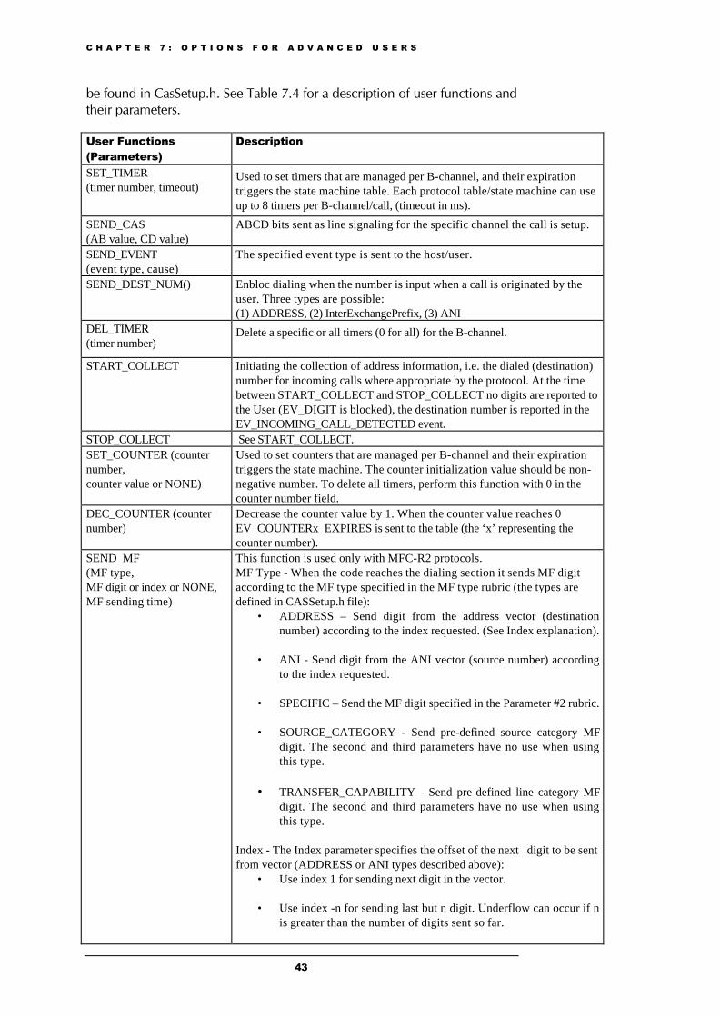
FunctionThe function rubric holds the name of the function to be activated when theaction specified in the action/events field occurs. Select the functions fromthe list of the eight functions defined in CasSetup.h. (e.g., START_COLLECT).When NONE is specified in this rubric, no function is executed. For adescription of the available functions and their parameters, please refer toTable 7.4.
Parameter #1, Parameter #2, Parameter #3These columns are used as the function’s parameters. NONE should beplaced when the parameter is not essential. The list of global parameters can
C H A P T E R 7 : O P T I O N S F O R A D V A N C E D U S E R S
43
be found in CasSetup.h. See Table 7.4 for a description of user functions andtheir parameters.
User Functions(Parameters)
Description
SET_TIMER(timer number, timeout)
Used to set timers that are managed per B-channel, and their expirationtriggers the state machine table. Each protocol table/state machine can useup to 8 timers per B-channel/call, (timeout in ms).
SEND_CAS(AB value, CD value)
ABCD bits sent as line signaling for the specific channel the call is setup.
SEND_EVENT(event type, cause)
The specified event type is sent to the host/user.
SEND_DEST_NUM() Enbloc dialing when the number is input when a call is originated by theuser. Three types are possible:(1) ADDRESS, (2) InterExchangePrefix, (3) ANI
DEL_TIMER(timer number)
Delete a specific or all timers (0 for all) for the B-channel.
START_COLLECT Initiating the collection of address information, i.e. the dialed (destination)number for incoming calls where appropriate by the protocol. At the timebetween START_COLLECT and STOP_COLLECT no digits are reported tothe User (EV_DIGIT is blocked), the destination number is reported in theEV_INCOMING_CALL_DETECTED event.
STOP_COLLECT See START_COLLECT.SET_COUNTER (counternumber,counter value or NONE)
Used to set counters that are managed per B-channel and their expirationtriggers the state machine. The counter initialization value should be non-negative number. To delete all timers, perform this function with 0 in thecounter number field.
DEC_COUNTER (counternumber)
Decrease the counter value by 1. When the counter value reaches 0EV_COUNTERx_EXPIRES is sent to the table (the ‘x’ representing thecounter number).
SEND_MF(MF type,MF digit or index or NONE,MF sending time)
This function is used only with MFC-R2 protocols.MF Type - When the code reaches the dialing section it sends MF digitaccording to the MF type specified in the MF type rubric (the types aredefined in CASSetup.h file):
• ADDRESS – Send digit from the address vector (destinationnumber) according to the index requested. (See Index explanation).
• ANI - Send digit from the ANI vector (source number) accordingto the index requested.
• SPECIFIC – Send the MF digit specified in the Parameter #2 rubric.
• SOURCE_CATEGORY - Send pre-defined source category MFdigit. The second and third parameters have no use when usingthis type.
• TRANSFER_CAPABILITY - Send pre-defined line category MFdigit. The second and third parameters have no use when usingthis type.
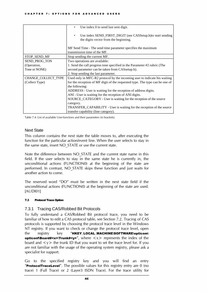
Index - The Index parameter specifies the offset of the next digit to be sentfrom vector (ADDRESS or ANI types described above):
• Use index 1 for sending next digit in the vector.
• Use index -n for sending last but n digit. Underflow can occur if nis greater than the number of digits sent so far.
C H A P T E R 7 : O P T I O N S F O R A D V A N C E D U S E R S
44
• Use index 0 to send last sent digit.
• Use index SEND_FIRST_DIGIT (see CASSetup.h)to start sendingthe digits vector from the beginning.
MF Send Time - The send time parameter specifies the maximumtransmission time of the MF.
STOP_SEND_MF Stop sending the current MF.SEND_PROG_TON (Operation,Tone or NONE)
Two operations are available:1. Send the call progress tone specified in the Parameter #2 rubric (Thesecond parameter can be taken from CASsetup.h).2. Stop sending the last parameter.
CHANGE_COLLECT_TYPE(Collect Type)
Used only in MFC-R2 protocol by the incoming user to indicate his waitingfor the reception of MF digit of the requested type. The type can be one ofthe following:ADDRESS - User is waiting for the reception of address digits.ANI - User is waiting for the reception of ANI digits.SOURCE_CATEGORY - User is waiting for the reception of the sourcecategory.TRANSFER_CAPABILITY - User is waiting for the reception of the sourcetransfer capability (line category).
Table 7.4: List of available User-functions and their parameters (in brackets).
Next StateThis column contains the next state the table moves to, after executing thefunction for the particular action/event line. When the user selects to stay inthe same state, insert NO_STATE or use the current state.
Note the difference between NO_STATE and the current state name in thisfield. If the user selects to stay in the same state he is currently in, theunconditional actions (FUNCTION0) at the beginning of the state areperformed. In contrast, NO_STATE skips these function and just waits foranother action to come.
The reserved word “DO” must be written in the next state field if theunconditional actions (FUNCTION0) at the beginning of the state are used.[AUDI01]
7.3 Protocol Trace Option
7.3.1 Tracing CAS/Robbed Bit ProtocolsTo fully understand a CAS/Robbed Bit protocol trace, you need to befamiliar of how to edit a CAS protocol table, see Section 7.2. Tracing of CASprotocols is supported by choosing the protocol trace level in the WindowsNT registry. If you want to check or change the protocol trace level, openthe registry key “HKEY_LOCAL_MACHINE\SOFTWARE\opticom\opticonf\Board#<x>\Trunk#<y>”, where <x> represents the index of theboard and <y> the trunk ID that you want to set the trace level for. If youare not familiar with the usage of the operating system registry, please ask aspecialist for support.
Go to the specified registry key and you will find an entry“ProtocolTraceLevel”. The possible values for this registry entry are 0 (notrace) 1 (Full Trace) or 2 (Layer3 ISDN Trace). For the trace utility for
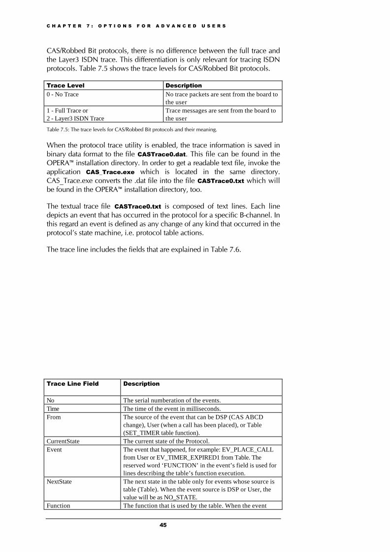
C H A P T E R 7 : O P T I O N S F O R A D V A N C E D U S E R S
45
CAS/Robbed Bit protocols, there is no difference between the full trace andthe Layer3 ISDN trace. This differentiation is only relevant for tracing ISDNprotocols. Table 7.5 shows the trace levels for CAS/Robbed Bit protocols.
Trace Level Description0 - No Trace No trace packets are sent from the board to
the user1 - Full Trace or2 - Layer3 ISDN Trace
Trace messages are sent from the board tothe user
Table 7.5: The trace levels for CAS/Robbed Bit protocols and their meaning.
When the protocol trace utility is enabled, the trace information is saved inbinary data format to the file CASTrace0.dat. This file can be found in theOPERA™ installation directory. In order to get a readable text file, invoke theapplication CAS_Trace.exe which is located in the same directory.CAS_Trace.exe converts the .dat file into the file CASTrace0.txt which willbe found in the OPERA™ installation directory, too.
The textual trace file CASTrace0.txt is composed of text lines. Each linedepicts an event that has occurred in the protocol for a specific B-channel. Inthis regard an event is defined as any change of any kind that occurred in theprotocol’s state machine, i.e. protocol table actions.
The trace line includes the fields that are explained in Table 7.6.
Trace Line Field Description
No The serial numberation of the events.Time The time of the event in milliseconds.From The source of the event that can be DSP (CAS ABCD
change), User (when a call has been placed), or Table(SET_TIMER table function).
CurrentState The current state of the Protocol.Event The event that happened, for example: EV_PLACE_CALL
from User or EV_TIMER_EXPIRED1 from Table. Thereserved word ‘FUNCTION’ in the event’s field is used forlines describing the table’s function execution.
NextState The next state in the table only for events whose source istable (Table). When the event source is DSP or User, thevalue will be as NO_STATE.
Function The function that is used by the table. When the event
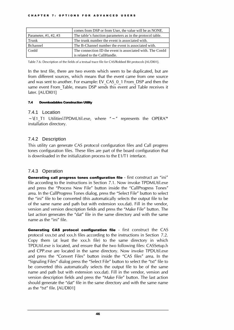
C H A P T E R 7 : O P T I O N S F O R A D V A N C E D U S E R S
46
comes from DSP or from User, the value will be as NONE.Parameter, #1, #2, #3 The table’s function parameters as in the protocol table.Trunk The trunk number the event is associated with.Bchannel The B-Channel number the event is associated with.ConId The connection ID the event is associated with. The ConId
is related to the CallHandle.
Table 7.6: Description of the fields of a textual trace file for CAS/Robbed Bit protocols [AUDI01].
In the text file, there are two events which seem to be duplicated, but arefrom different sources, which means that the event came from one sourceand was sent to another. For example: EV_CAS_0_1 From_DSP and then thesame event From_Table, means DSP sends this event and Table receives itlater. [AUDI01]
7.4 Downloadables Construction Utility
7.4.1 Location~\E1_T1 Utilities\TPDMUtil.exe, where “~” represents the OPERA™installation directory.
7.4.2 DescriptionThis utility can generate CAS protocol configuration files and Call progresstones configuration files. These files are part of the board configuration thatis downloaded in the initialization process to the E1/T1 interface.
7.4.3 OperationGenerating call progress tones configuration file - first construct an “ini”file according to the instructions in Section 7.1. Now invoke TPDMUtil.exeand press the “Process New File” button inside the “CallProgress Tones”area. In the CallProgress Tones dialog, press the “Select File” button to selectthe “ini” file to be converted (this automatically selects the output file to beof the same name and path but with extension xxx.dat). Fill in the vendor,version and version description fields and press the “Make File” button. Thelast action generates the “dat” file in the same directory and with the samename as the “ini” file.
Generating CAS protocol configuration file - first construct the CASprotocol xxx.txt and xxx.h files according to the instructions in Section 7.2.Copy them (at least the xxx.h file) to the same directory in whichTPDUtil.exe is located, and ensure that the two following files: CASSetup.hand CPP.exe are located in the same directory. Now invoke TPDUtil.exeand press the “Convert Files” button inside the “CAS files” area. In the“Signaling Files” dialog press the “Select File” button to select the “txt” file tobe converted (this automatically selects the output file to be of the samename and path but with extension xxx.dat). Fill in the vendor, version andversion description fields and press the “Make File” button. The last actionshould generate the “dat” file in the same directory and with the same nameas the “txt” file. [AUDI01]
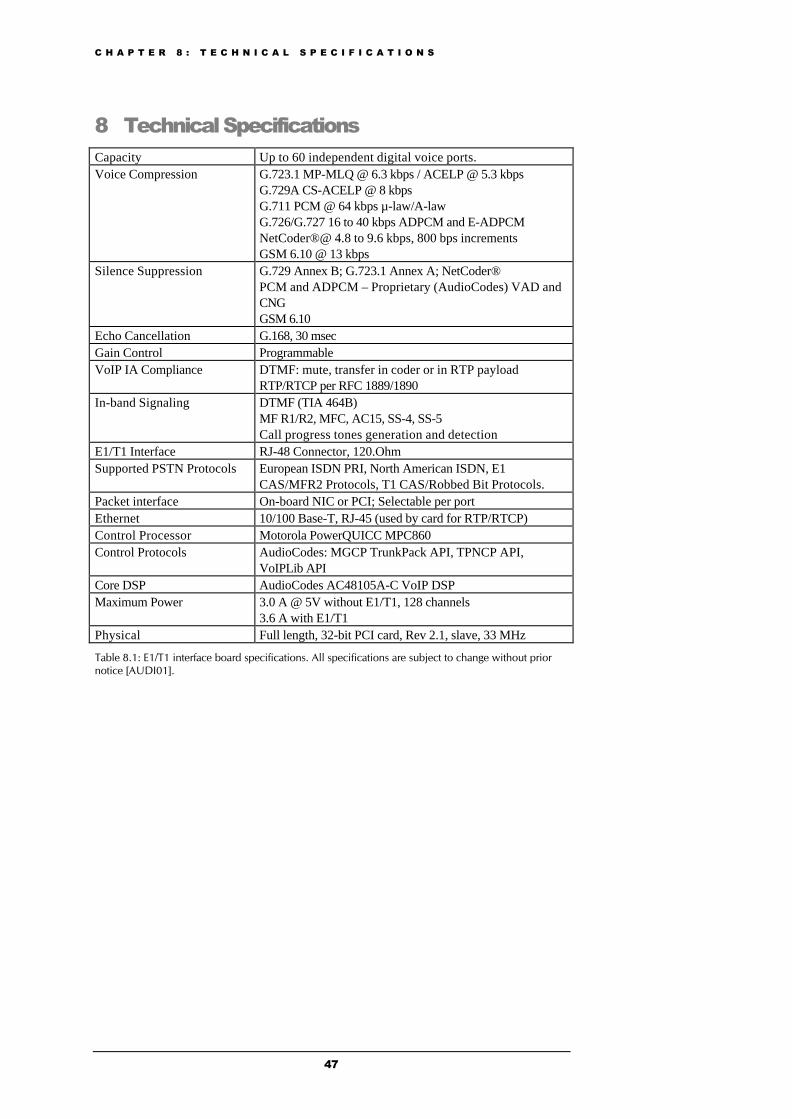
C H A P T E R 8 : T E C H N I C A L S P E C I F I C A T I O N S
47
8 Technical SpecificationsCapacity Up to 60 independent digital voice ports.Voice Compression G.723.1 MP-MLQ @ 6.3 kbps / ACELP @ 5.3 kbps
G.729A CS-ACELP @ 8 kbpsG.711 PCM @ 64 kbps µ-law/A-lawG.726/G.727 16 to 40 kbps ADPCM and E-ADPCMNetCoder®@ 4.8 to 9.6 kbps, 800 bps incrementsGSM 6.10 @ 13 kbps
Silence Suppression G.729 Annex B; G.723.1 Annex A; NetCoder®PCM and ADPCM – Proprietary (AudioCodes) VAD andCNGGSM 6.10
Echo Cancellation G.168, 30 msecGain Control ProgrammableVoIP IA Compliance DTMF: mute, transfer in coder or in RTP payload
RTP/RTCP per RFC 1889/1890In-band Signaling DTMF (TIA 464B)
MF R1/R2, MFC, AC15, SS-4, SS-5Call progress tones generation and detection
E1/T1 Interface RJ-48 Connector, 120.OhmSupported PSTN Protocols European ISDN PRI, North American ISDN, E1
CAS/MFR2 Protocols, T1 CAS/Robbed Bit Protocols.Packet interface On-board NIC or PCI; Selectable per portEthernet 10/100 Base-T, RJ-45 (used by card for RTP/RTCP)Control Processor Motorola PowerQUICC MPC860Control Protocols AudioCodes: MGCP TrunkPack API, TPNCP API,
VoIPLib APICore DSP AudioCodes AC48105A-C VoIP DSPMaximum Power 3.0 A @ 5V without E1/T1, 128 channels
3.6 A with E1/T1Physical Full length, 32-bit PCI card, Rev 2.1, slave, 33 MHz
Table 8.1: E1/T1 interface board specifications. All specifications are subject to change without priornotice [AUDI01].

C H A P T E R 9 : R E F E R E N C E S
48
9 References[AUDI01] AudioCodes, User Manual and Library Reference.
[INTM01] INT Media Group Incorporated, http://isp.webopedia.com.
[STT100] Standards Committee T1 Telecommunications,http://www.its.bldrdoc.gov/projects/telecomglossary2000.
C H A P T E R 1 0 : G L O S S A R Y O F T E R M S
49
10 Glossary of Terms10.1 ANIShort for automatic number identification, a service that provides thetelephone number of an incoming call. ANI is used for a variety of functions-- by receiving the incoming telephone number, telephone companies candirect a call to the proper long distance carrier's equipment; it can helpidentify the caller's address to speed response time to 911 calls; and it canroute an 800 call to the nearest vendor. ISDN supports ANI [INTM01].
10.2 CLICalling line identification (CLI): At a minimum, the calling line identificationincludes a single calling party number; it may also include a second callingparty number, a calling party subaddress, and redirecting numberinformation. Calling line identification may not include any calling partynumber due to interworking, or because of an interaction with the CLIRsupplementary service [STT100].