Embed Size (px)
Citation preview
ANL/NE-14/7
User Manual for EXODUS II Mesh Converter
Nuclear Engineering Division
About Argonne National Laboratory
Argonne is a U.S. Department of Energy laboratory managed by UChicago Argonne, LLC
under contract DE-AC02-06CH11357. The Laboratory’s main facility is outside Chicago,
at 9700 South Cass Avenue, Argonne, Illinois 60439. For information about Argonne
and its pioneering science and technology programs, see www.anl.gov.
DOCUMENT AVAILABILITY
Online Access: U.S. Department of Energy (DOE) reports produced after 1991 and a
growing number of pre-1991 documents are available free via DOE’s SciTech Connect
(http://www.osti.gov/scitech/)
Reports not in digital format may be purchased by the public from the
National Technical Information Service (NTIS):
U.S. Department of Commerce
National Technical Information Service
5301 Shawnee Rd
Alexandra, VA 22312
www.ntis.gov
Phone: (800) 553-NTIS (6847) or (703) 605-6000
Fax: (703) 605-6900
Email: [email protected]
Reports not in digital format are available to DOE and DOE contractors from the
Office of Scientific and Technical Information (OSTI):
U.S. Department of Energy
Office of Scientific and Technical Information
P.O. Box 62
Oak Ridge, TN 37831-0062
www.osti.gov
Phone: (865) 576-8401
Fax: (865) 576-5728
Disclaimer
This report was prepared as an account of work sponsored by an agency of the United States Government. Neither the United States
Government nor any agency thereof, nor UChicago Argonne, LLC, nor any of their employees or officers, makes any warranty, express
or implied, or assumes any legal liability or responsibility for the accuracy, completeness, or usefulness of any information, apparatus,
product, or process disclosed, or represents that its use would not infringe privately owned rights. Reference herein to any specific
commercial product, process, or service by trade name, trademark, manufacturer, or otherwise, does not necessarily constitute or imply
its endorsement, recommendation, or favoring by the United States Government or any agency thereof. The views and opinions of
document authors expressed herein do not necessarily state or reflect those of the United States Government or any agency thereof,
Argonne National Laboratory, or UChicago Argonne, LLC.
ANL/NE-14/7
User Manual for EXODUS II Mesh Converter
prepared by
E. R. Shemon and C. W. Attaway
Nuclear Engineering Division, Argonne National Laboratory
August 15, 2014
ABSTRACT
A mesh conversion program has been developed to convert EXODUS II-formatted finite element
meshes to the ascii format used by the PROTEUS-SN neutronics code developed at Argonne National
Laboratory. This manual contains instructions, usage examples, and methodology for the mesh
converter.
The PROTEUS-SN neutronics code requires a finite element mesh input file in one of several
accepted formats (ascii, nemesh, pntmesh, or bgpmesh). None of these file formats are directly
produced by conventional finite element file modeling codes, therefore format conversion is required.
Currently, most finite element meshes are prepared using the Cubit program developed by Sandia
National Laboratory. Cubit can export finite element meshes in a variety of formats including the
portable EXODUS II format. EXODUS II files are binary files with NetCDF data storage structures
designed to handle large object-oriented arrays. While a specialized EXODUS II application
programming interface (API) exists to query EXODUS II data, the general NetCDF API can also be used
for the same purpose.
The described program improves upon a previous tool which had limited flexibility and
performance. Notably, the new converter successfully converts EXODUS II files generated with more
recent versions of Cubit (version 13+) and has no limitation on mesh size (total number of vertices or
elements). The converter queries data from the EXODUS II file using NetCDF API commands, reads the
data in the file, reorganizes it, and writes it to the ascii file format used by PROTEUS-SN.
User Manual for EXODUS II Mesh Converter
August 15, 2014
2
TABLE OF CONTENTS
Abstract ............................................................................................................................................1
Table of Contents .............................................................................................................................2 1. Introduction ................................................................................................................................3
1.1 Input File Summary .............................................................................................................3
1.2 Output File Summary ...........................................................................................................3 2. Code Installation and Usage ......................................................................................................5
2.1 Quick Start Guide ................................................................................................................3
2.2 NetCDF Library Requirements ............................................................................................5
2.3 Building the Converter .........................................................................................................7
2.4 Execution Syntax .................................................................................................................7
2.5 Limitations ...........................................................................................................................8 3. Conversion Methodology...........................................................................................................9
3.1 EXODUS II Overview .........................................................................................................9
3.1.1 Dimensions Section ...................................................................................................9
3.1.2 Variables Section .......................................................................................................9
3.1.3 Data Section ............................................................................................................10
3.2 Conversion Process ............................................................................................................11
3.2.1 Command Line Input and Output File Creation ......................................................11
3.2.2 Reading the Dimensions ..........................................................................................12
3.2.3 Reading the Variables .............................................................................................12
3.2.4 Writing Coordinates and Basic Block Information .................................................12
3.2.5 Connectivity Remapping .........................................................................................12
3.2.6 Boundary Information .............................................................................................13
3.3 Output File Descriptions ....................................................................................................15
3.3.1 ASCII File Format ...................................................................................................15
3.3.2 Report File ...............................................................................................................16 4. Benchmark Problems ...............................................................................................................18
5. Summary ..................................................................................................................................20 6. References ................................................................................................................................21 APPENDIX A ................................................................................................................................22 APPENDIX B ................................................................................................................................23
User Manual for EXODUS II Mesh Converter
August 15, 2014
3
1. Introduction This chapter describes the basic functionality of the EXODUS II mesh converter program, whose
purpose is to convert EXODUS II finite element meshes to the ascii format used by the PROTEUS
transport code developed at Argonne National Laboratory. The program is written in C++ and depends
on a C++-enabled NetCDF [3] library to access and interpret data collected from the input EXODUS II
mesh.
1.1 Input File Summary
The program requires input in the form of one or more EXODUS II finite element meshes with
proper extension type (“.e” or “.exo”). The EXODUS II files must contain data following the EXODUS II
naming conventions and must not be empty.
The Cubit meshing program [4] developed by Sandia National Laboratory is typically used to create
meshes in EXODUS II format and has been routinely used to for PROTEUS-SN neutronics analysis. This
converter program is compatible with EXODUS II meshes exported from Cubit versions 12+. Note that
Cubit 13+ EXODUS II meshes have slightly different keywords for the vertex coordinates, and this
difference is handled inside the converter automatically without user intervention.
1.2 Output File Summary
For each EXODUS II input mesh, two output files are produced: the ascii-formatted mesh for
PROTEUS and an informative report file. Both files are generated in the same directory as the input
EXODUS II mesh and follow a natural naming convention (input file Sample.e yields output files
Sample.ascii and Sample_REPORT.txt). The report file is provided as a user convenience to ensure
accurate conversion and enable debugging – the conversion procedure is echoed in this file during the
conversion process, including any errors encountered.
1.3 Quick Start Guide
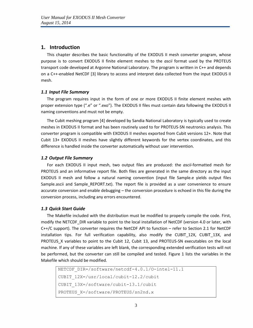
The Makefile included with the distribution must be modified to properly compile the code. First,
modify the NETCDF_DIR variable to point to the local installation of NetCDF (version 4.0 or later, with
C++/C support). The converter requires the NetCDF API to function – refer to Section 2.1 for NetCDF
installation tips. For full verification capability, also modify the CUBIT_12X, CUBIT_13X, and
PROTEUS_X variables to point to the Cubit 12, Cubit 13, and PROTEUS-SN executables on the local
machine. If any of these variables are left blank, the corresponding extended verification tests will not
be performed, but the converter can still be compiled and tested. Figure 1 lists the variables in the
Makefile which should be modified.
NETCDF_DIR=/software/netcdf-4.0.1/O-intel-11.1
CUBIT_12X=/usr/local/cubit-12.2/cubit
CUBIT_13X=/software/cubit-13.1/cubit
PROTEUS_X=/software/PROTEUS/sn2nd.x
User Manual for EXODUS II Mesh Converter
August 15, 2014
4
Figure 1. Makefile variables to be modified for installing and testing converter.
Next, the code can be compiled using “make” to create the executable, and “make check” to test
basic performance. Optional extended testing with Cubit and PROTEUS are available by typing “make
verify” after also providing paths to Cubit and PROTEUS executable locations in CUBIT_12X,
CUBIT_13X, and PROTEUS_X variables as shown in the figure above.
$> make
$> make check
$> make verify (only works if Cubit & PROTEUS are installed)
Figure 2. Commands to compile and test the converter.
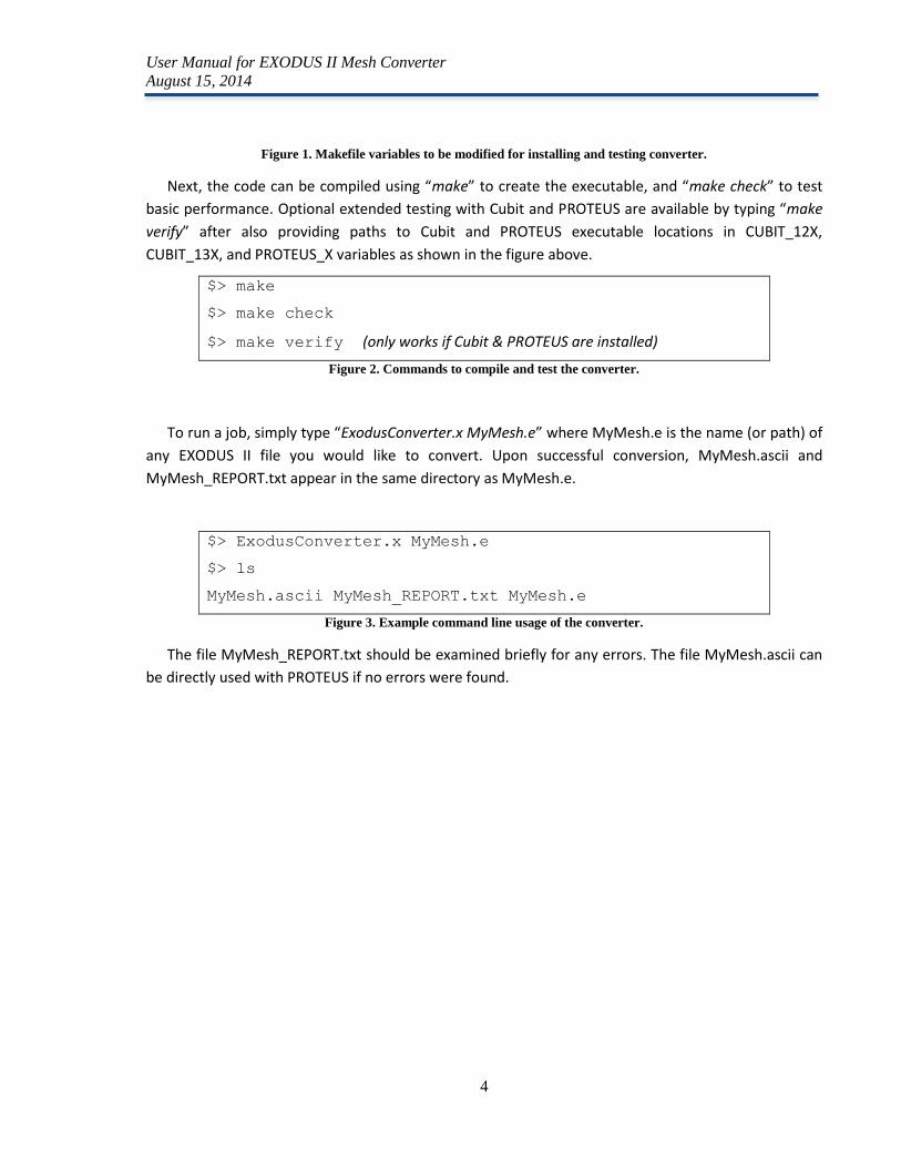
To run a job, simply type “ExodusConverter.x MyMesh.e” where MyMesh.e is the name (or path) of
any EXODUS II file you would like to convert. Upon successful conversion, MyMesh.ascii and
MyMesh_REPORT.txt appear in the same directory as MyMesh.e.
$> ExodusConverter.x MyMesh.e
$> ls
MyMesh.ascii MyMesh_REPORT.txt MyMesh.e
Figure 3. Example command line usage of the converter.
The file MyMesh_REPORT.txt should be examined briefly for any errors. The file MyMesh.ascii can
be directly used with PROTEUS if no errors were found.
User Manual for EXODUS II Mesh Converter
August 15, 2014
5
2. Code Installation and Usage This section describes how to install and use the EXODUS II finite element mesh converter.
2.1 NetCDF Library Requirements
The EXODUS II mesh converter has a dependency on the NetCDF library. It uses the NetCDF API to
query data from EXODUS II files which are actually specialized NetCDF data files. As mentioned in the
previous section, the NETCDF_DIR variable in the Makefile must point to a local installation of the
NetCDF library, version 4.0+, with C and C++ capabilities enabled. The NetCDF library must be built
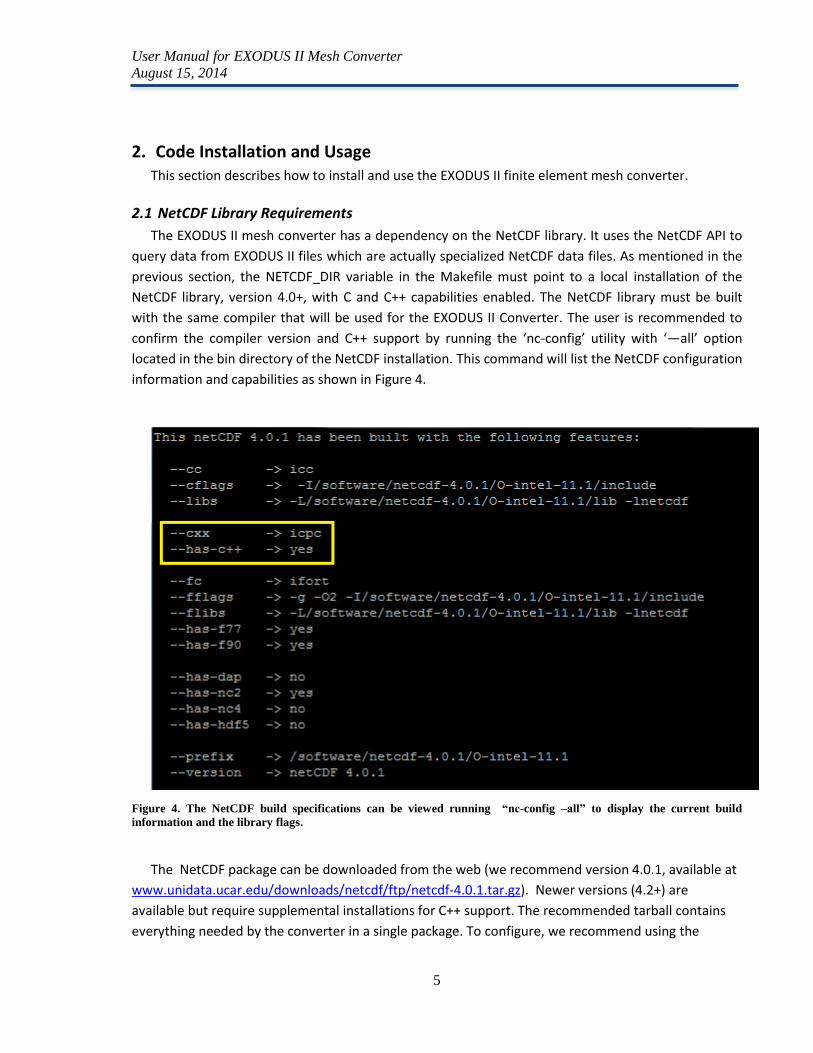
with the same compiler that will be used for the EXODUS II Converter. The user is recommended to
confirm the compiler version and C++ support by running the ‘nc-config’ utility with ‘—all’ option
located in the bin directory of the NetCDF installation. This command will list the NetCDF configuration
information and capabilities as shown in Figure 4.
Figure 4. The NetCDF build specifications can be viewed running “nc-config –all” to display the current build
information and the library flags.
The NetCDF package can be downloaded from the web (we recommend version 4.0.1, available at
www.unidata.ucar.edu/downloads/netcdf/ftp/netcdf-4.0.1.tar.gz). Newer versions (4.2+) are
available but require supplemental installations for C++ support. The recommended tarball contains
everything needed by the converter in a single package. To configure, we recommend using the
User Manual for EXODUS II Mesh Converter
August 15, 2014
6
options in Figure 5, where the compilers should be consistent with those you plan to use for the
EXODUS II converter. The “--disable-netcdf-4 --disable-dap-remote-tests” options disable extended
NetCDF functionalities that may require additional dependencies that are unnecessary for the
converter.
$> ./configure --prefix=/software/netcdf-4.0.1/O-intel-11.1 CC=icc F77=ifort
FC=ifort F90=ifort CXX=icpc --disable-netcdf-4 --disable-dap-remote-tests
$> make check install
Figure 5. Recommended NetCDF configuration options for NetCDF 4.0 or 4.1 versions.
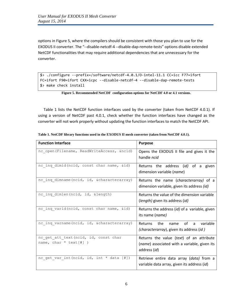
Table 1 lists the NetCDF function interfaces used by the converter (taken from NetCDF 4.0.1). If
using a version of NetCDF past 4.0.1, check whether the function interfaces have changed as the
converter will not work properly without updating the function interfaces to match the NetCDF API.
Table 1. NetCDF library functions used in the EXODUS II mesh converter (taken from NetCDF 4.0.1).
Function Interface Purpose
nc_open(Filename, ReadWriteAccess, &ncid) Opens the EXODUS II file and gives it the
handle ncid
nc_inq_dimid(ncid, const char name, &id) Returns the address (id) of a given
dimension variable (name)
nc_inq_dimname(ncid, id, &characterarray) Returns the name (characterarray) of a
dimension variable, given its address (id)
nc_inq_dimlen(ncid, id, &length) Returns the value of the dimension variable
(length) given its address (id)
nc_inq_varid(ncid, const char name, &id) Returns the address (id) of a variable, given
its name (name)
nc_inq_varname(ncid, id, &characterarray) Returns the name of a variable
(characterarray), given its address (id )
nc_get_att_text(ncid, id, const char
name, char * text[#] )
Returns the value (text) of an attribute
(name) associated with a variable, given its
address (id)
nc_get_var_int(ncid, id, int * data [#]) Retrieve entire data array (data) from a
variable data array, given its address (id)
User Manual for EXODUS II Mesh Converter
August 15, 2014
7
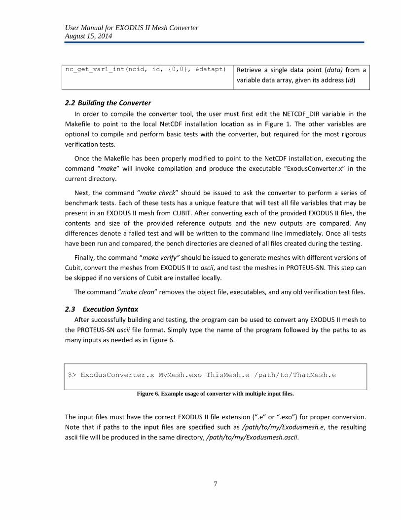
nc_get_var1_int(ncid, id, {0,0}, &datapt) Retrieve a single data point (data) from a
variable data array, given its address (id)
2.2 Building the Converter
In order to compile the converter tool, the user must first edit the NETCDF_DIR variable in the
Makefile to point to the local NetCDF installation location as in Figure 1. The other variables are
optional to compile and perform basic tests with the converter, but required for the most rigorous
verification tests.
Once the Makefile has been properly modified to point to the NetCDF installation, executing the
command “make” will invoke compilation and produce the executable “ExodusConverter.x” in the
current directory.
Next, the command “make check” should be issued to ask the converter to perform a series of
benchmark tests. Each of these tests has a unique feature that will test all file variables that may be
present in an EXODUS II mesh from CUBIT. After converting each of the provided EXODUS II files, the
contents and size of the provided reference outputs and the new outputs are compared. Any
differences denote a failed test and will be written to the command line immediately. Once all tests
have been run and compared, the bench directories are cleaned of all files created during the testing.
Finally, the command “make verify” should be issued to generate meshes with different versions of
Cubit, convert the meshes from EXODUS II to ascii, and test the meshes in PROTEUS-SN. This step can
be skipped if no versions of Cubit are installed locally.
The command “make clean” removes the object file, executables, and any old verification test files.
2.3 Execution Syntax
After successfully building and testing, the program can be used to convert any EXODUS II mesh to
the PROTEUS-SN ascii file format. Simply type the name of the program followed by the paths to as
many inputs as needed as in Figure 6.
$> ExodusConverter.x MyMesh.exo ThisMesh.e /path/to/ThatMesh.e
Figure 6. Example usage of converter with multiple input files.
The input files must have the correct EXODUS II file extension (“.e” or “.exo”) for proper conversion.
Note that if paths to the input files are specified such as /path/to/my/Exodusmesh.e, the resulting
ascii file will be produced in the same directory, /path/to/my/Exodusmesh.ascii.
User Manual for EXODUS II Mesh Converter
August 15, 2014
8
2.4 Limitations
The converter supports Cubit element types which are also supported by PROTEUS. Therefore,
some element types available within Cubit are not valid element types for the converter and
PROTEUS. When generating a mesh with Cubit, use only the following element types: BAR, BAR2,
BAR3, TRI, TRI3, TRI6, QUAD, QUAD4, QUAD8, QUAD9, TETRA, TETRA4, TETRA10, HEX, HEX8, HEX10. In
particular, ensure that the EXODUS II mesh does not contain SHELL or TRISHELL element types which
are not supported by PROTEUS-SN or the converter. SHELL or TRISHELL element types are typically
assigned by default if the user fails to specify an element type – thus the user should carefully check
that they have assigned all element blocks properly.
User Manual for EXODUS II Mesh Converter
August 15, 2014
9
3. Conversion Methodology This chapter contains a description of the code methodology and is intended for an advanced user
who wishes to modify the converter or understand exactly how the conversion is performed. We focus
on describing EXODUS II finite element files created by Cubit 12+. EXODUS II files created by other
software may have slightly different formats.
3.1 EXODUS II Overview
The EXODUS II file type is binary, portable, and cannot be read in a standard text editor. To read
the contents of an EXODUS II file, the NetCDF utility “ncdump” can be used to dump the content to
plain text. Each EXODUS II mesh file contains three important data sections: “dimensions”, “variables”,
and “data”.
3.1.1 Dimensions Section
The “dimensions” section of an EXODUS II file defines values for the following “dimension”
variables. These dimensions are used to declare arrays appearing later in the file.
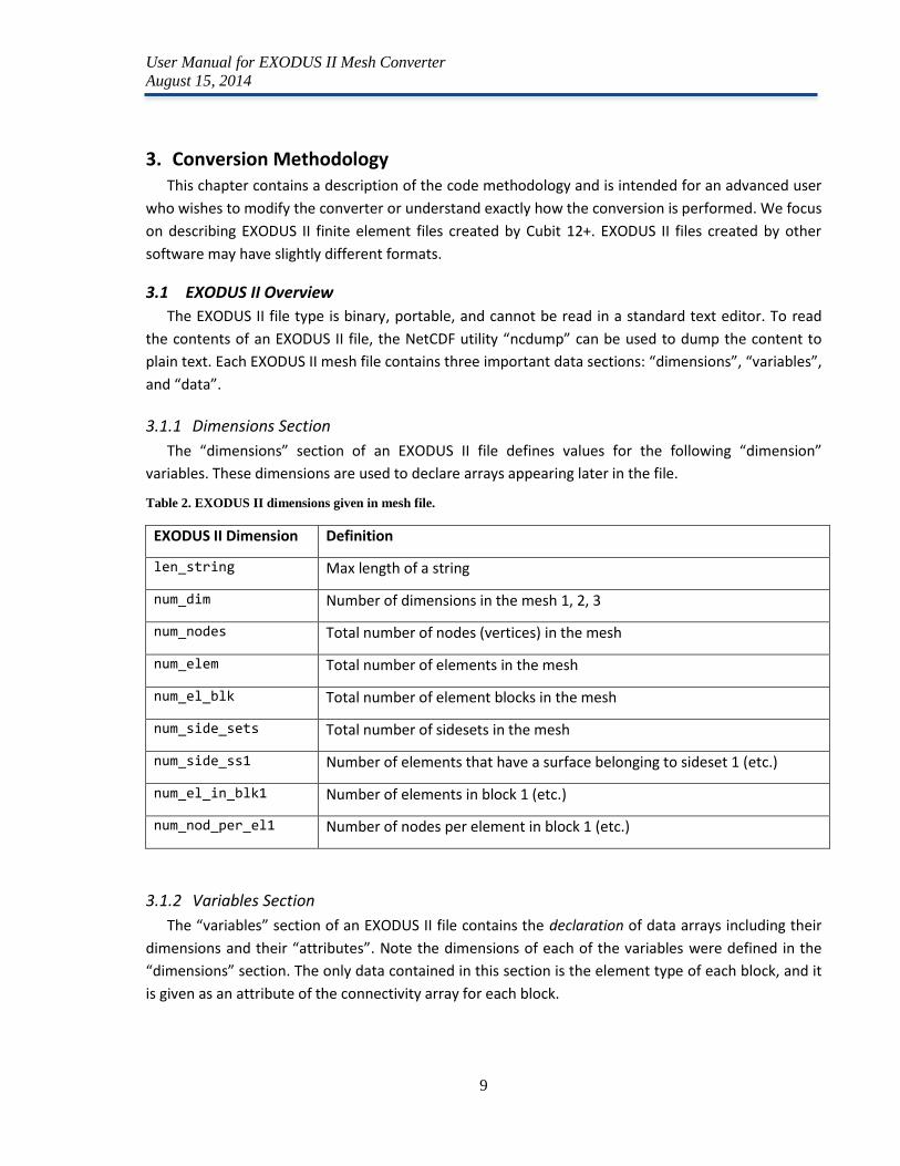
Table 2. EXODUS II dimensions given in mesh file.
EXODUS II Dimension Definition
len_string Max length of a string
num_dim Number of dimensions in the mesh 1, 2, 3
num_nodes Total number of nodes (vertices) in the mesh
num_elem Total number of elements in the mesh
num_el_blk Total number of element blocks in the mesh
num_side_sets Total number of sidesets in the mesh
num_side_ss1 Number of elements that have a surface belonging to sideset 1 (etc.)
num_el_in_blk1 Number of elements in block 1 (etc.)
num_nod_per_el1 Number of nodes per element in block 1 (etc.)
3.1.2 Variables Section
The “variables” section of an EXODUS II file contains the declaration of data arrays including their
dimensions and their “attributes”. Note the dimensions of each of the variables were defined in the
“dimensions” section. The only data contained in this section is the element type of each block, and it
is given as an attribute of the connectivity array for each block.
User Manual for EXODUS II Mesh Converter
August 15, 2014
10
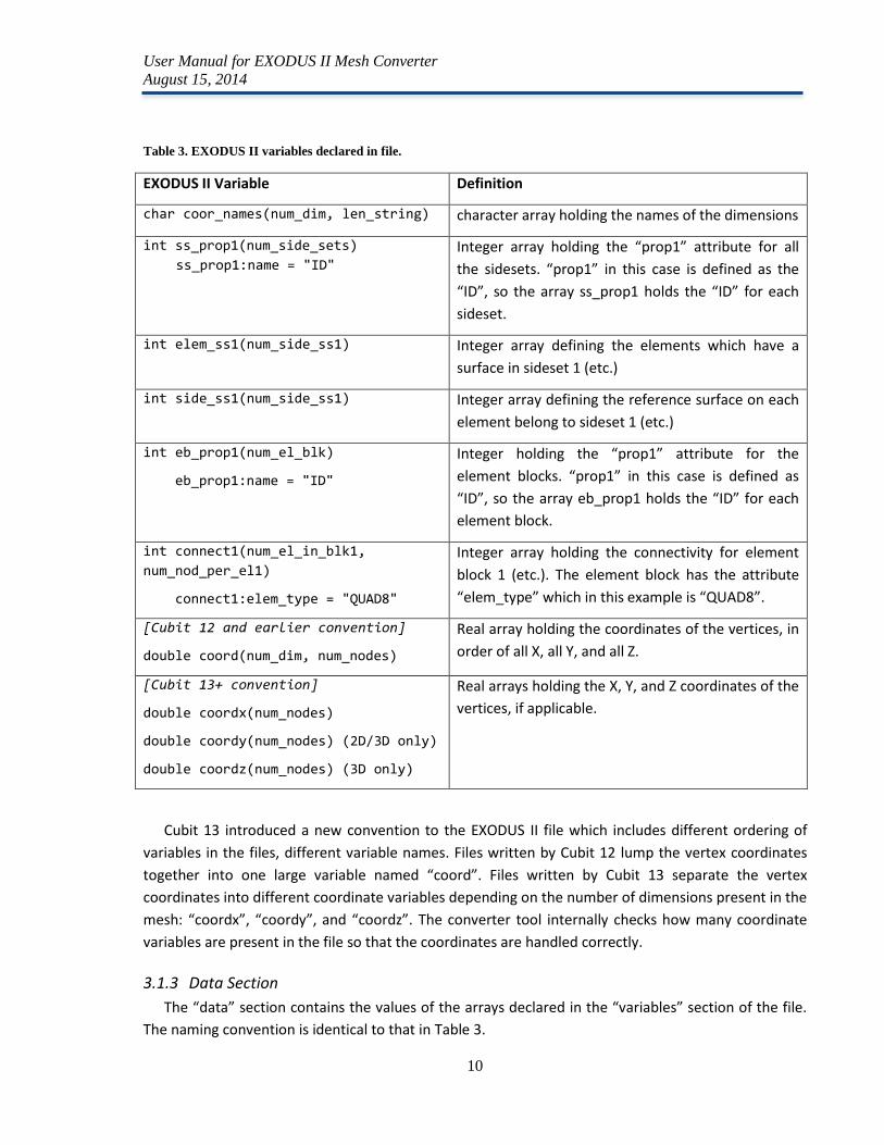
Table 3. EXODUS II variables declared in file.
EXODUS II Variable Definition
char coor_names(num_dim, len_string) character array holding the names of the dimensions
int ss_prop1(num_side_sets)
ss_prop1:name = "ID"
Integer array holding the “prop1” attribute for all
the sidesets. “prop1” in this case is defined as the
“ID”, so the array ss_prop1 holds the “ID” for each
sideset.
int elem_ss1(num_side_ss1) Integer array defining the elements which have a
surface in sideset 1 (etc.)
int side_ss1(num_side_ss1) Integer array defining the reference surface on each
element belong to sideset 1 (etc.)
int eb_prop1(num_el_blk)
eb_prop1:name = "ID"
Integer holding the “prop1” attribute for the
element blocks. “prop1” in this case is defined as
“ID”, so the array eb_prop1 holds the “ID” for each
element block.
int connect1(num_el_in_blk1,
num_nod_per_el1)
connect1:elem_type = "QUAD8"
Integer array holding the connectivity for element
block 1 (etc.). The element block has the attribute
“elem_type” which in this example is “QUAD8”.
[Cubit 12 and earlier convention]
double coord(num_dim, num_nodes)
Real array holding the coordinates of the vertices, in
order of all X, all Y, and all Z.
[Cubit 13+ convention]
double coordx(num_nodes)
double coordy(num_nodes) (2D/3D only)
double coordz(num_nodes) (3D only)
Real arrays holding the X, Y, and Z coordinates of the
vertices, if applicable.
Cubit 13 introduced a new convention to the EXODUS II file which includes different ordering of
variables in the files, different variable names. Files written by Cubit 12 lump the vertex coordinates
together into one large variable named “coord”. Files written by Cubit 13 separate the vertex
coordinates into different coordinate variables depending on the number of dimensions present in the
mesh: “coordx”, “coordy”, and “coordz”. The converter tool internally checks how many coordinate
variables are present in the file so that the coordinates are handled correctly.
3.1.3 Data Section
The “data” section contains the values of the arrays declared in the “variables” section of the file.
The naming convention is identical to that in Table 3.
User Manual for EXODUS II Mesh Converter
August 15, 2014
11
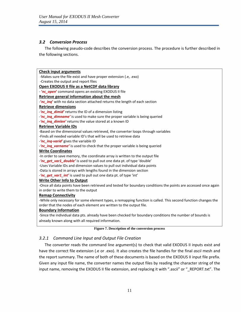
3.2 Conversion Process
The following pseudo-code describes the conversion process. The procedure is further described in
the following sections.
Check input arguments -Makes sure the file exist and have proper extension (.e, .exo) -Creates the output and report files
Open EXODUS II file as a NetCDF data library - ‘nc_open’ command opens an existing EXODUS II file Retrieve general information about the mesh -‘nc_inq’ with no data section attached returns the length of each section
Retrieve dimensions -‘nc_inq_dimid’ returns the ID of a dimension listing -‘nc_inq_dimname’ is used to make sure the proper variable is being queried -‘nc_inq_dimlen’ returns the value stored at a known ID
Retrieve Variable IDs -Based on the dimensional values retrieved, the converter loops through variables -Finds all needed variable ID’s that will be used to retrieve data -‘nc_inq-varid’ gives the variable ID -‘nc_inq_varname’ is used to check that the proper variable is being queried
Write Coordinates -In order to save memory, the coordinate array is written to the output file -‘nc_get_var1_double’ is used to pull out one data pt. of type ‘double’ -Uses Variable IDs and dimension values to pull out individual data points -Data is stored in arrays with lengths found in the dimension section -‘nc_get_var1_int’ is used to pull out one data pt. of type ‘int’
Write Other Info to Output -Once all data points have been retrieved and tested for boundary conditions the points are accessed once again in order to write them to the output
Remap Connectivity -While only necessary for some element types, a remapping function is called. This second function changes the order that the nodes of each element are written to the output file.
Boundary Information -Since the individual data pts. already have been checked for boundary conditions the number of bounds is
already known along with all required information.
Figure 7. Description of the conversion process
3.2.1 Command Line Input and Output File Creation
The converter reads the command line argument(s) to check that valid EXODUS II inputs exist and
have the correct file extension (.e or .exo). It also creates the file handles for the final ascii mesh and
the report summary. The name of both of these documents is based on the EXODUS II input file prefix.
Given any input file name, the converter names the output files by reading the character string of the
input name, removing the EXODUS II file extension, and replacing it with “.ascii” or “_REPORT.txt”. The
User Manual for EXODUS II Mesh Converter
August 15, 2014
12
converter can process files outside of the current working directory, but output files are created in the
same directory as the input file, not the current working directory.
3.2.2 Reading the Dimensions
The converter opens the EXODUS II file as a NetCDF data library using the nc_open command. The
converter uses NetCDF commands (see Error! Reference source not found.) to parse through the
dimension section and retrieve the information needed to initialize array and set loop variables later
on for the variable section. The key information queried here is the number of dimensions, number of
element blocks in the mesh, total number of nodes, number of sidesets, number of elements held in
each block, and the number of nodes per element in each block. These values are written to the ascii
file.
3.2.3 Reading the Variables
Using the dimensions retrieved from the dimension section, the converter sets loops to collect the
IDs of each block, sideset, and connectivity variable. An ID is essentially an “address” in the file. In
order to ensure the correct variable is read, a variable name check is implemented in each major
variable retrieval loop.
3.2.4 Writing Coordinates and Basic Block Information
At this point, the location and size of important data has been determined. The converter begins
process the vertex array point by point rather than as a whole. This point-by-point method takes more
time than processing everything at once, but removes any size limitations on the input file. At this
stage the vertex coordinates are all written to the output file.
Next, the basic block information is written to the output file: the number of elements in the block,
number of boundary elements in the block, number of nodes per element in the block and the
equation and interpolation orders of the elements. Each EXODUS II element type is then mapped to a
PROTEUS-SN element type, and the PROTEUS-SN element type is written to file along with the block
Region ID and the connectivity array.
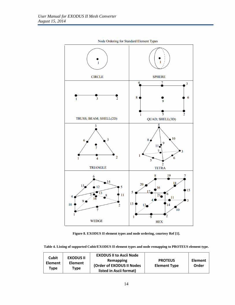
3.2.5 Connectivity Remapping
The connectivity of each element given in the EXODUS II file format is based on EXODUS II element
type ordering [1], shown in Figure 8. However, each EXODUS II element type must be mapped via the
converter to a PROTEUS-SN element type as shown in Table 4. For element types with different vertex
ordering, the connectivity array is changed in order to follow the PROTEUS-SN convention.
Note that CIRCLE, SPHERE and SHELL(3D) EXODUS II element types are not supported as they are
not realistic for neutronics simulations. WEDGE may be added in the future although it is not currently
supported. Appendix B contains figures that define the element types and node ordering supported by
PROTEUS.
User Manual for EXODUS II Mesh Converter
August 15, 2014
13
3.2.6 Boundary Information
During the data retrieval stage, each element was tested to see if it contained a boundary surface.
These elements are then written out to the output file followed by the array of sideset IDs to which
each element belongs. Finally, the converter prints a list sideset IDs corresponding to the boundary
elements, as well as the element number within the block and the reference surface number
containing the boundary surface.
User Manual for EXODUS II Mesh Converter
August 15, 2014
14
Figure 8. EXODUS II element types and node ordering, courtesy Ref [1].
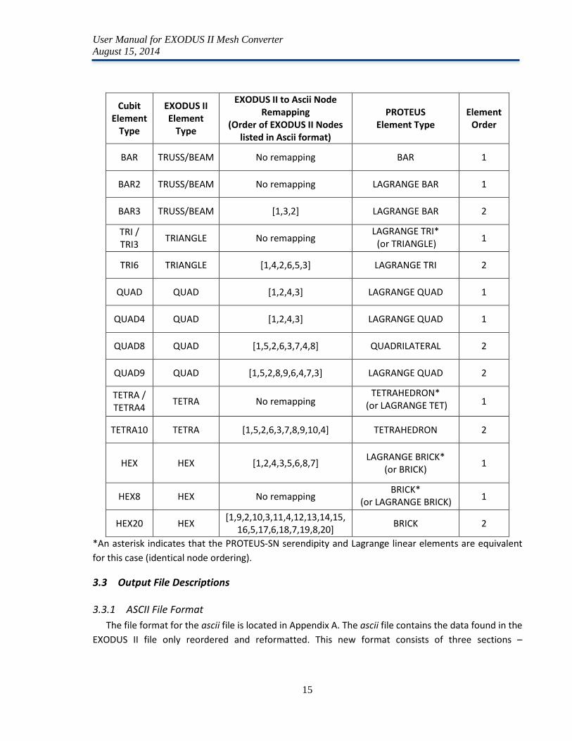
Table 4. Listing of supported Cubit/EXODUS II element types and node remapping to PROTEUS element type.
Cubit Element
Type
EXODUS II Element
Type
EXODUS II to Ascii Node Remapping
(Order of EXODUS II Nodes listed in Ascii format)
PROTEUS Element Type
Element Order
User Manual for EXODUS II Mesh Converter
August 15, 2014
15
Cubit Element
Type
EXODUS II Element
Type
EXODUS II to Ascii Node Remapping
(Order of EXODUS II Nodes listed in Ascii format)
PROTEUS Element Type
Element Order
BAR TRUSS/BEAM No remapping BAR 1
BAR2 TRUSS/BEAM No remapping LAGRANGE BAR 1
BAR3 TRUSS/BEAM [1,3,2] LAGRANGE BAR 2
TRI / TRI3
TRIANGLE No remapping LAGRANGE TRI*
(or TRIANGLE) 1
TRI6 TRIANGLE [1,4,2,6,5,3] LAGRANGE TRI 2
QUAD QUAD [1,2,4,3] LAGRANGE QUAD 1
QUAD4 QUAD [1,2,4,3] LAGRANGE QUAD 1
QUAD8 QUAD [1,5,2,6,3,7,4,8] QUADRILATERAL 2
QUAD9 QUAD [1,5,2,8,9,6,4,7,3] LAGRANGE QUAD 2
TETRA / TETRA4
TETRA No remapping TETRAHEDRON*
(or LAGRANGE TET) 1
TETRA10 TETRA [1,5,2,6,3,7,8,9,10,4] TETRAHEDRON 2
HEX HEX [1,2,4,3,5,6,8,7] LAGRANGE BRICK*
(or BRICK) 1
HEX8 HEX No remapping BRICK*
(or LAGRANGE BRICK) 1
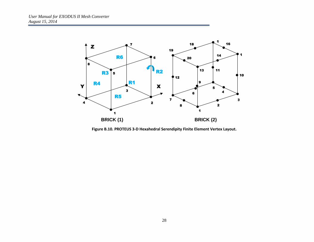
HEX20 HEX [1,9,2,10,3,11,4,12,13,14,15,
16,5,17,6,18,7,19,8,20] BRICK 2
*An asterisk indicates that the PROTEUS-SN serendipity and Lagrange linear elements are equivalent
for this case (identical node ordering).
3.3 Output File Descriptions
3.3.1 ASCII File Format
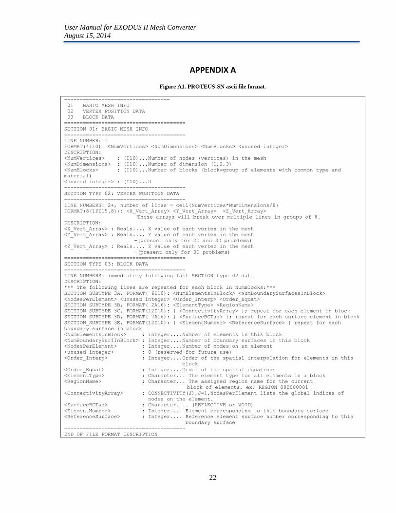
The file format for the ascii file is located in Appendix A. The ascii file contains the data found in the
EXODUS II file only reordered and reformatted. This new format consists of three sections –
User Manual for EXODUS II Mesh Converter
August 15, 2014
16
information regarding the mesh as a whole, the entire coordinate table listing, and the individual block
data.
The general mesh information is always located on the first line and states the total number of
vertices in the mesh, the number of dimension, the total number of blocks that are present in the
mesh, and lastly an unused integer set to zero for later use.
The second section is a list of all coordinates in the mesh ordered by dimension with all X
dimension coordinates being listed first, then the Y’s, and lastly the Z’s. Only the coordinates listed in
the EXODUS II file are printed to the ascii file, for example, in 2D, X and Y vertices only are printed.
The final section holds information regarding each element block. The first line for each block holds
the number of elements in the block, the number of boundary conditions, and how many nodes are
attached to each element, an unused integer, the order of interpolation, and the equation order.
Following this line is a listing of the element type of the entire block and the region name. The
connectivity arrays that hold the node ordering are then listed. The connectivity of a given element
type may or may not be reordered from the EXODUS II depending on the element type and
interpolation order found during the conversion process. The final pieces of information for this
section are the sidesets that correspond to the boundary elements found in the side sets, the
boundary elements (numbered by element number within the specific element block ), and lastly the
boundary surface associated with each boundary element.
3.3.2 Report File
For each conversion performed, a report file is written to show the success or failure of each step
in the conversion process. While it is easy to read the error immediately from the command line, the
report allows for review later on if needed.
User Manual for EXODUS II Mesh Converter
August 15, 2014
17
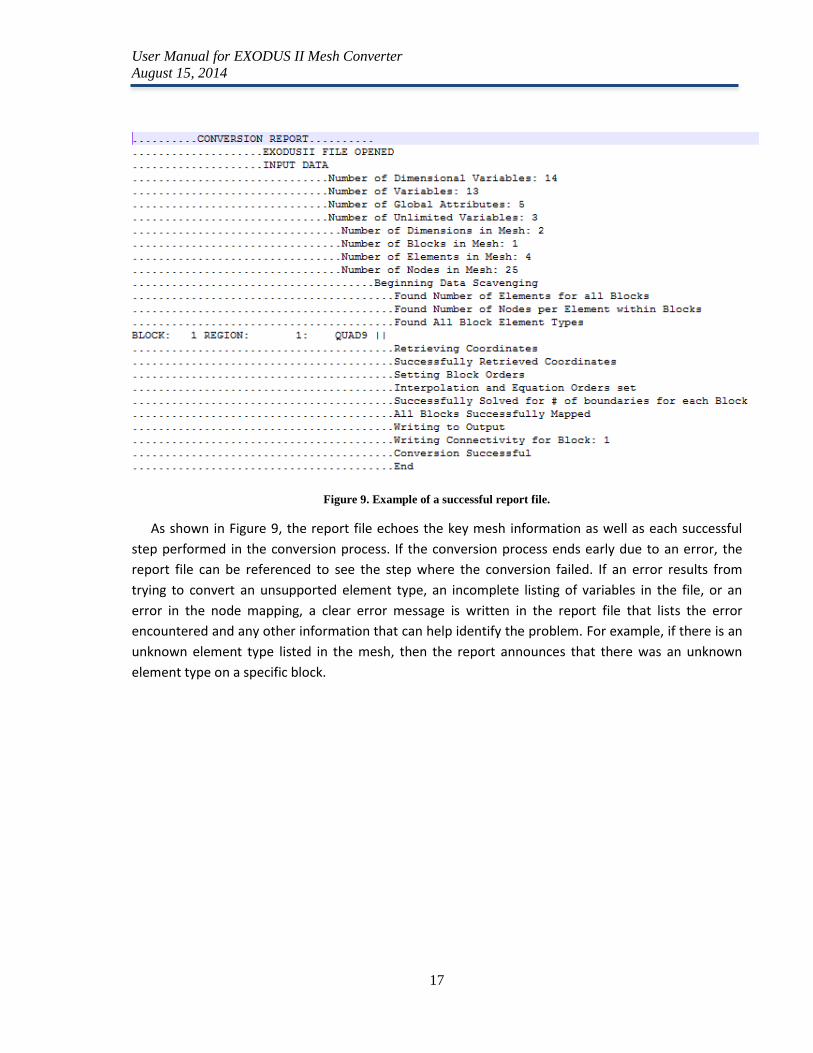
Figure 9. Example of a successful report file.
As shown in Figure 9, the report file echoes the key mesh information as well as each successful
step performed in the conversion process. If the conversion process ends early due to an error, the
report file can be referenced to see the step where the conversion failed. If an error results from
trying to convert an unsupported element type, an incomplete listing of variables in the file, or an
error in the node mapping, a clear error message is written in the report file that lists the error
encountered and any other information that can help identify the problem. For example, if there is an
unknown element type listed in the mesh, then the report announces that there was an unknown
element type on a specific block.
User Manual for EXODUS II Mesh Converter
August 15, 2014
18
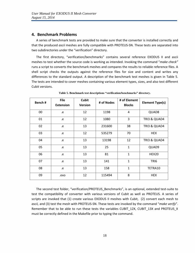
4. Benchmark Problems A series of benchmark tests are provided to make sure that the converter is installed correctly and
that the produced ascii meshes are fully compatible with PROTEUS-SN. These tests are separated into
two subdirectories under the “verification” directory.
The first directory, “verification/benchmarks” contains several reference EXODUS II and ascii
meshes to test whether the source code is working as intended. Invoking the command “make check”
runs a script to converts the benchmark meshes and compares the results to reliable reference files. A
shell script checks the outputs against the reference files for size and content and writes any
differences to the standard output. A description of the benchmark test meshes is given in Table 5.
The tests are intended to cover meshes containing various element types, sizes, and also test different
Cubit versions.
Table 5. Benchmark test descriptions “verification/benchmarks” directory.
Bench # File
Extension
Cubit
Version # of Nodes
# of Element
Blocks Element Type(s)
00 .e 12 1198 4 QUAD8
01 .e 12 1080 3 TRI3 & QUAD4
02 .e 13 231600 38 TRI3 & QUAD4
03 .e 12 535279 70 HEX
04 .e 13 13198 12 TRI3 & QUAD4
05 .e 13 25 1 QUAD9
06 .e 13 81 1 HEX20
07 .e 13 141 1 TRI6
08 .e 13 158 1 TETRA10
09 .exo 12 115494 8 HEX
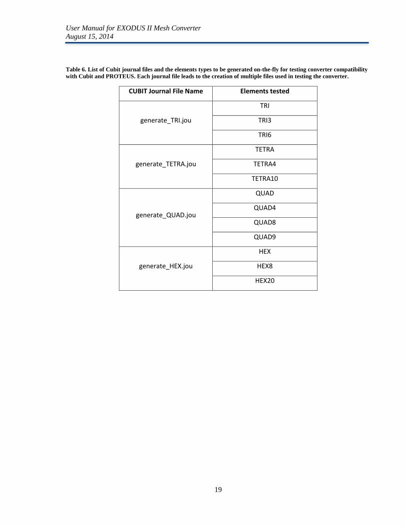
The second test folder, “verification/PROTEUS_Benchmarks”, is an optional, extended test-suite to
test the compatibility of converter with various versions of Cubit as well as PROTEUS. A series of
scripts are invoked that (1) create various EXODUS II meshes with Cubit, (2) convert each mesh to
ascii, and (3) test the mesh with PROTEUS-SN. These tests are invoked by the command “make verify”.
Remember that to be able to run these tests the variables CUBIT_12X, CUBIT_13X and PROTEUS_X
must be correctly defined in the Makefile prior to typing the command.
User Manual for EXODUS II Mesh Converter
August 15, 2014
19
Table 6. List of Cubit journal files and the elements types to be generated on-the-fly for testing converter compatibility
with Cubit and PROTEUS. Each journal file leads to the creation of multiple files used in testing the converter.
CUBIT Journal File Name Elements tested
generate_TRI.jou
TRI
TRI3
TRI6
generate_TETRA.jou
TETRA
TETRA4
TETRA10
generate_QUAD.jou
QUAD
QUAD4
QUAD8
QUAD9
generate_HEX.jou
HEX
HEX8
HEX20

User Manual for EXODUS II Mesh Converter
August 15, 2014
20
5. Summary A new EXODUS II finite element mesh converter has been developed to convert EXODUS II meshes
(typically created by Cubit) to PROTEUS-SN ascii mesh format. The conversion program replaces an old
converter which had limitations on mesh size and compatibility issues with Cubit. The new program
works with different versions of Cubit (any version 12+) and has no limitation on EXODUS II file size.
Error checking, error reporting and usage syntax have also been greatly improved. The converter is
limited to element types supported by PROTEUS-SN (a subset of those produced by Cubit).
For questions, assistance, or to obtain the converter, please contact [email protected].
User Manual for EXODUS II Mesh Converter
August 15, 2014
21
6. References
1. Schoof, Larry A. and Yarberry, Victor R., “EXODUS II: A Finite Element Data Model” Sandia National
Laboratories, Computational Mechanics and Visualization Department, November, 1995.
2. Shemon, E. R., M. A. Smith, C.H. Lee, and A. Marin-Lafleche, “PROTEUS-SN User Manual”, ANL/NE-
14/6, Argonne National Laboratory, June 30, 2014.
3. Russ Rew, Glenn Davis, Steve Emmerson, Harvey Davies, Ed Hartnett, Dennis Heimbigner and Ward
Fisher, “NetCDF Documentation” UCAR & UCP , Unidata, 2008.
4. Ted Blacker, Randy Morris, “Cubit 13.1 User Documentation”, Sandia National Laboratories,
Albuquerque, NM, 2012.
User Manual for EXODUS II Mesh Converter
August 15, 2014
22
APPENDIX A
Figure A1. PROTEUS-SN ascii file format.
==================================
01 BASIC MESH INFO
02 VERTEX POSITION DATA
03 BLOCK DATA
=======================================
SECTION 01: BASIC MESH INFO
=======================================
LINE NUMBER: 1
FORMAT(4I10): <NumVertices> <NumDimensions> <NumBlocks> <unused integer>
DESCRIPTION:
<NumVertices> : (I10)...Number of nodes (vertices) in the mesh
<NumDimensions> : (I10)...Number of dimension (1,2,3)
<NumBlocks> : (I10)...Number of blocks (block=group of elements with common type and
material)
<unused integer> : (I10)...0
=======================================
SECTION TYPE 02: VERTEX POSITION DATA
=======================================
LINE NUMBERS: 2+, number of lines = ceil{NumVertices*NumDimensions/8}
FORMAT(8(1PE15.8)): <X_Vert_Array> <Y_Vert_Array> <Z_Vert_Array>
-These arrays will break over multiple lines in groups of 8.
DESCRIPTION:
<X_Vert_Array> : Reals.... X value of each vertex in the mesh
<Y_Vert_Array> : Reals.... Y value of each vertex in the mesh
-(present only for 2D and 3D problems)
<Z_Vert_Array> : Reals.... Z value of each vertez in the mesh
-(present only for 3D problems)
=======================================
SECTION TYPE 03: BLOCK DATA
=======================================
LINE NUMBERS: immediately following last SECTION type 02 data
DESCRIPTION:
*** The following lines are repeated for each block in NumBlocks:***
SECTION SUBTYPE 3A, FORMAT( 6I10): <NumElementsInBlock> <NumBoundarySurfacesInBlock>
<NodesPerElement> <unused integer> <Order_Interp> <Order_Equat>
SECTION SUBTYPE 3B, FORMAT( 2A16): <ElementType> <RegionName>
SECTION SUBTYPE 3C, FORMAT(12I10): { <ConnectivityArray> }; repeat for each element in block
SECTION SUBTYPE 3D, FORMAT( 7A16): { <SurfaceBCTag> }; repeat for each surface element in block
SECTION_SUBTYPE 3E, FORMAT(12I10): { <ElementNumber> <ReferenceSurface> } repeat for each
boundary surface in block
<NumElementsInBlock> : Integer....Number of elements in this block
<NumBoundarySurfInBlock> : Integer....Number of boundary surfaces in this block
<NodesPerElement> : Integer....Number of nodes on an element
<unused integer> : 0 (reserved for future use)
<Order_Interp> : Integer....Order of the spatial interpolation for elements in this
block
<Order_Equat> : Integer....Order of the spatial equations
<ElementType> : Character... The element type for all elements in a block
<RegionName> : Character... The assigned region name for the current
block of elements, ex. REGION_000000001
<ConnectivityArray> : CONNECTIVITY(J),J=1,NodesPerElement lists the global indices of
nodes on the element.
<SurfaceBCTag> : Character.... (REFLECTIVE or VOID)
<ElementNumber> : Integer.... Element corresponding to this boundary surface
<ReferenceSurface> : Integer.... Reference element surface number corresponding to this
boundary surface
=======================================
END OF FILE FORMAT DESCRIPTION
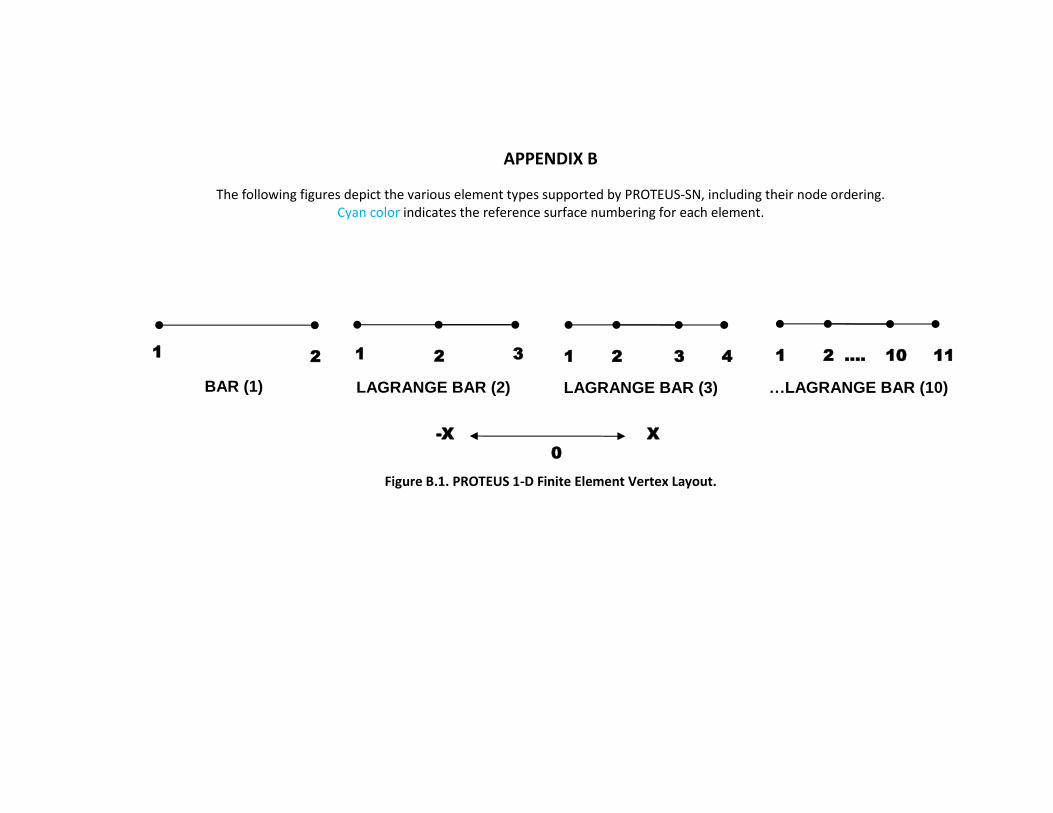
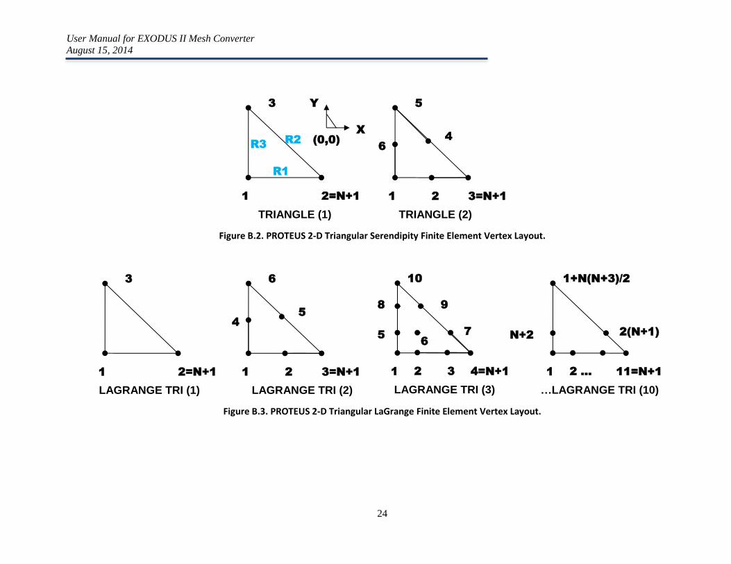
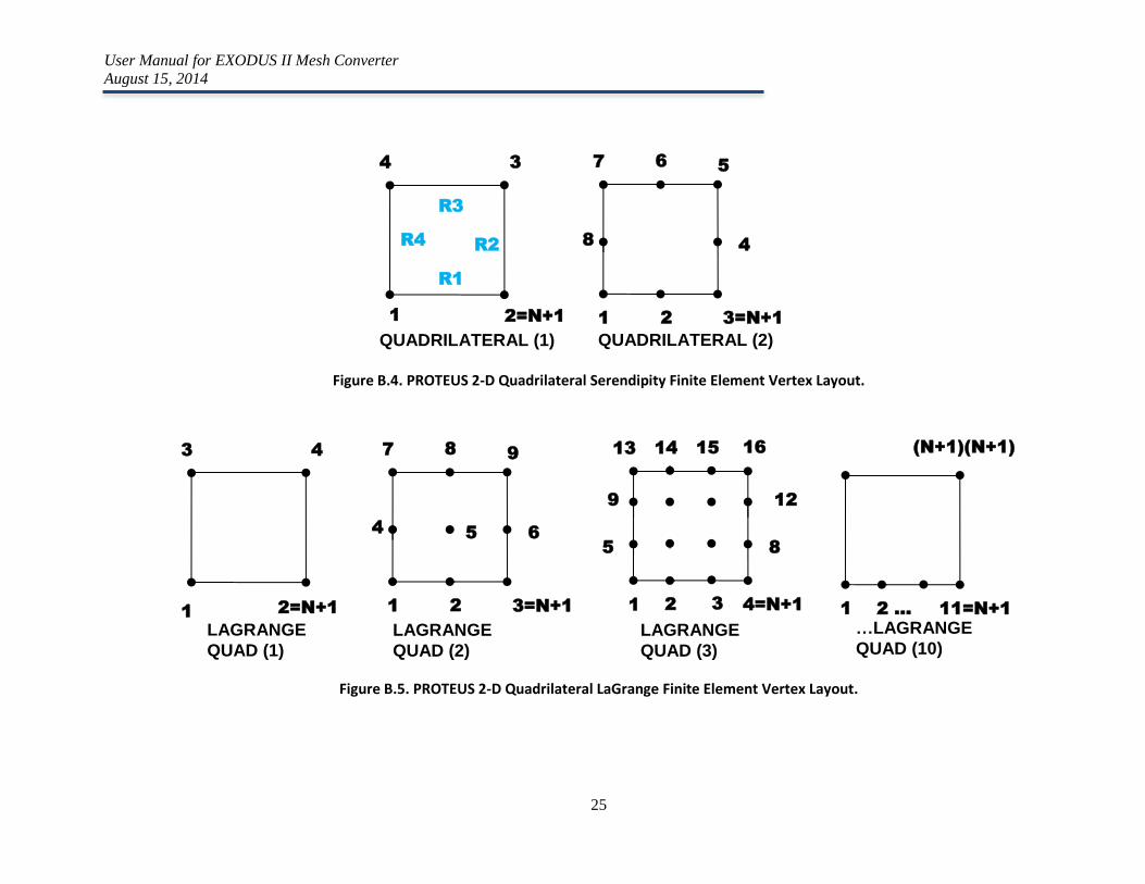
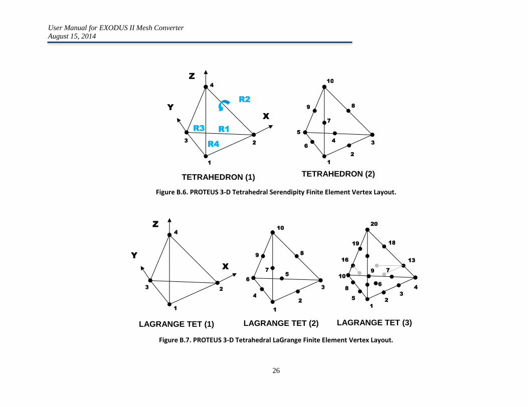
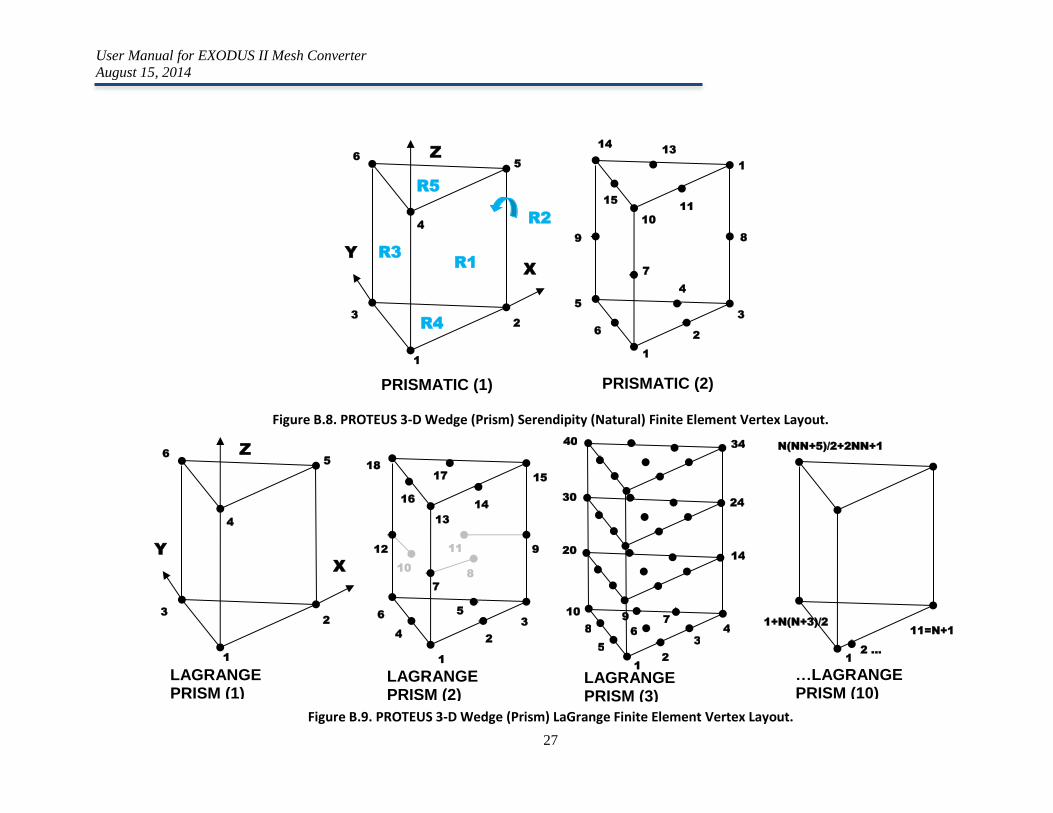
APPENDIX B
The following figures depict the various element types supported by PROTEUS-SN, including their node ordering. Cyan color indicates the reference surface numbering for each element.
Figure B.1. PROTEUS 1-D Finite Element Vertex Layout.
1 2 1 3 2
BAR (1) LAGRANGE BAR (2)
1 4 2 3
LAGRANGE BAR (3)
1 11 2 .... 10
…LAGRANGE BAR (10)
-X X
0
User Manual for EXODUS II Mesh Converter
August 15, 2014
24
Figure B.2. PROTEUS 2-D Triangular Serendipity Finite Element Vertex Layout.
Figure B.3. PROTEUS 2-D Triangular LaGrange Finite Element Vertex Layout.
1 2=N+1
TRIANGLE (1)
Y
X
(0,0)
3
1 3=N+1
TRIANGLE (2)
5
2
6
4
R1
R2 R3
1 2=N+1
LAGRANGE TRI (1)
3
1 3=N+1
LAGRANGE TRI (2)
6
2
4
5
1 4=N+1
LAGRANGE TRI (3)
10
2
5 7
3
6
8 9
1 11=N+1
…LAGRANGE TRI (10)
1+N(N+3)/2
2 …
N+2 2(N+1)
User Manual for EXODUS II Mesh Converter
August 15, 2014
25
Figure B.4. PROTEUS 2-D Quadrilateral Serendipity Finite Element Vertex Layout.
Figure B.5. PROTEUS 2-D Quadrilateral LaGrange Finite Element Vertex Layout.
1 2=N+1
QUADRILATERAL (1)
4 3
1 3=N+1 2
8 4
7 6 5
R1
R2
R3
R4
QUADRILATERAL (2)
1 2=N+1
LAGRANGE
QUAD (1)
3
1 3=N+1 2
4
4
5 6
7 8 9
1 4=N+1 2
5 8
13 14
3
12 9
15 16
1 11=N+1 2 …
(N+1)(N+1)
LAGRANGE
QUAD (2)
LAGRANGE
QUAD (3)
…LAGRANGE
QUAD (10)
User Manual for EXODUS II Mesh Converter
August 15, 2014
26
Figure B.6. PROTEUS 3-D Tetrahedral Serendipity Finite Element Vertex Layout.
Figure B.7. PROTEUS 3-D Tetrahedral LaGrange Finite Element Vertex Layout.
1
TETRAHEDRON (1)
Z
X
Y
2 3
4
1
2
3 4
5
6
7
8 9
10
R1 R3
R4
R2
TETRAHEDRON (2)
LAGRANGE TET (1)
Z
X
Y
1
2
3
4
7 9
10
8
5
18 19
20
1
2 3
4
1
2
3
4
5
6
7
8 9
10
6
13 16
LAGRANGE TET (2) LAGRANGE TET (3)
User Manual for EXODUS II Mesh Converter
August 15, 2014
27
Figure B.8. PROTEUS 3-D Wedge (Prism) Serendipity (Natural) Finite Element Vertex Layout.
Figure B.9. PROTEUS 3-D Wedge (Prism) LaGrange Finite Element Vertex Layout.
1
PRISMATIC (1)
Z
X
Y
2
3
4
5
6
1
2
3
4
6
5
7
8 9
10
11
1
2
13 14
15
R1
R3
R4
R5
R2
PRISMATIC (2)
LAGRANGE PRISM (1)
N(NN+5)/2+2NN+1
1
2
3
4
5
6
7
8
9 10
40
20
30
14
24
34
1
2 …
11=N+1
1+N(N+3)/2
1
Z
X
Y
2
3
4
5
6
1
2
3
5 6
4
7
8
9 11 12
10
13
14
15 17
18
16
LAGRANGE PRISM (2)
LAGRANGE PRISM (3)
…LAGRANGE PRISM (10)
User Manual for EXODUS II Mesh Converter
August 15, 2014
28
Figure B.10. PROTEUS 3-D Hexahedral Serendipity Finite Element Vertex Layout.
BRICK (1)
1
2
3
4
5
6
7
8
X Y
Z
1
3
5
7
13
1
5
1
7
19
2
4 6
8
9
10
11
12
14
16 18
20
R1
R3
R4
R5
R6
R2
BRICK (2)
User Manual for EXODUS II Mesh Converter
August 15, 2014
29
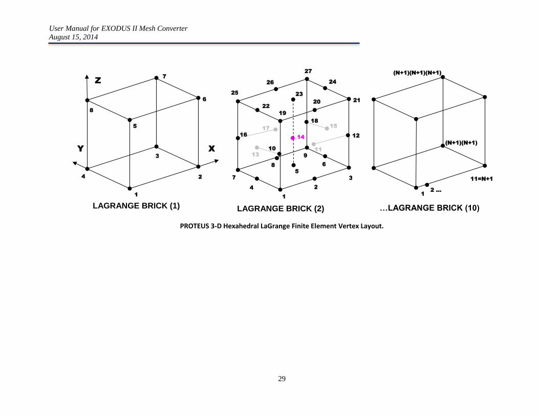
PROTEUS 3-D Hexahedral LaGrange Finite Element Vertex Layout.
LAGRANGE BRICK (1)
1
2
3
4
5
6
7
8
X Y
Z
1
3
9
7
19
21
27
25
2
6 8
4
10
12
18
16
20
9
24 26
22
1
11=N+1
(N+1)(N+1)(N+1)
2 …
(N+1)(N+1)
5
11
15 17
13
14
23
LAGRANGE BRICK (2) …LAGRANGE BRICK (10)

Argonne National Laboratory is a U.S. Department of Energy
laboratory managed by UChicago Argonne, LLC
Nuclear Engineering Division Argonne National Laboratory
9700 South Cass Avenue, Bldg. 208
Argonne, IL 60439-4842
www.anl.gov