Embed Size (px)
Citation preview

USER MANUAL – EN
IN 14172 Recumbent inSPORTline Gemini R200

2
CONTENTS
SAFETY PRECAUTIONS ........................................................................................................................ 3
PARTS DETAILS ..................................................................................................................................... 4
SCREW BAG ........................................................................................................................................... 6
EXPLODED DRAWING ........................................................................................................................... 7
PARTS LIST ............................................................................................................................................ 8
ASSEMBLY STEPS .............................................................................................................................. 12
CONSOLE OPERATION INSTRUCTIONS ........................................................................................... 15
DISPLAY INTRODUCTION ............................................................................................................... 15
DISPLAY AND START-UP OF THE BOOT WINDOW ...................................................................... 15
KEY INSTRUCTIONS ........................................................................................................................ 15
PROGRAM FUNCTION ..................................................................................................................... 16
PROGRAM GRAPHS ............................................................................................................................ 20
TERMS AND CONDITIONS OF WARRANTY, WARRANTY CLAIMS ................................................. 21
3
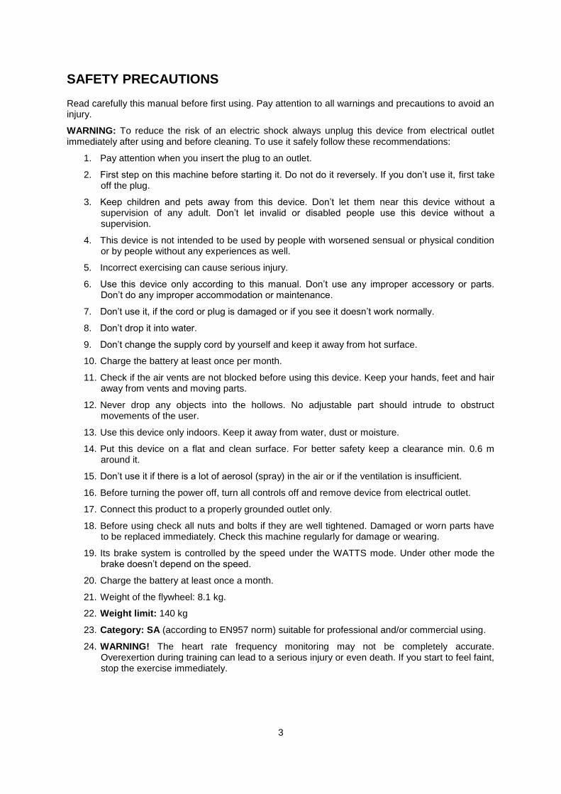
SAFETY PRECAUTIONS
Read carefully this manual before first using. Pay attention to all warnings and precautions to avoid an injury.
WARNING: To reduce the risk of an electric shock always unplug this device from electrical outlet immediately after using and before cleaning. To use it safely follow these recommendations:
1. Pay attention when you insert the plug to an outlet.
2. First step on this machine before starting it. Do not do it reversely. If you don’t use it, first take off the plug.
3. Keep children and pets away from this device. Don’t let them near this device without a supervision of any adult. Don’t let invalid or disabled people use this device without a supervision.
4. This device is not intended to be used by people with worsened sensual or physical condition or by people without any experiences as well.
5. Incorrect exercising can cause serious injury.
6. Use this device only according to this manual. Don’t use any improper accessory or parts. Don’t do any improper accommodation or maintenance.
7. Don’t use it, if the cord or plug is damaged or if you see it doesn’t work normally.
8. Don’t drop it into water.
9. Don’t change the supply cord by yourself and keep it away from hot surface.
10. Charge the battery at least once per month.
11. Check if the air vents are not blocked before using this device. Keep your hands, feet and hair away from vents and moving parts.
12. Never drop any objects into the hollows. No adjustable part should intrude to obstruct movements of the user.
13. Use this device only indoors. Keep it away from water, dust or moisture.
14. Put this device on a flat and clean surface. For better safety keep a clearance min. 0.6 m around it.
15. Don’t use it if there is a lot of aerosol (spray) in the air or if the ventilation is insufficient.
16. Before turning the power off, turn all controls off and remove device from electrical outlet.
17. Connect this product to a properly grounded outlet only.
18. Before using check all nuts and bolts if they are well tightened. Damaged or worn parts have to be replaced immediately. Check this machine regularly for damage or wearing.
19. Its brake system is controlled by the speed under the WATTS mode. Under other mode the brake doesn’t depend on the speed.
20. Charge the battery at least once a month.
21. Weight of the flywheel: 8.1 kg.
22. Weight limit: 140 kg
23. Category: SA (according to EN957 norm) suitable for professional and/or commercial using.
24. WARNING! The heart rate frequency monitoring may not be completely accurate. Overexertion during training can lead to a serious injury or even death. If you start to feel faint, stop the exercise immediately.

4
PARTS DETAILS
A. Console mast set
B. Main frame set
C. Front stabilizer set
D. Rear stabilizer set
E. Handrail tube set
F. Back seat pad
G. Seat pad

5
H. Console mast decoration cover (L/R)
I. Left and right pedal set
J. Console set (LED)
K. Water bottle holder
L. Accessory holder
M. Console front decoration cover (L/R)
N. Console lower decoration cover

6
SCREW BAG
Item Description Qty Item Description Qty
K01 Truss inner hex screw M8xP1.25x25 4 K13 Truss inner hex screw M8xP1.25x20 4
K02 Spring washer M8 4 K14 Spring washer M8 4
K03 Washer Φ8xΦ16x1.5t 4 K15 Flat washer ∮8x∮16x1.0t 4
K04 CKS inner hex steel screw M8xP1.25x20
4 K16 Truss cross screw M4xP0.7x12
2
K05 Washer ∮8x∮12x1.0t 4 K17 Truss cross screw M5xP0.8x10 4
K06 Truss inner hex screw M8xP1.25x40 4 K18 Truss cross screw M5xP0.8x12 2
K07 Washer Φ8xΦ16x1.5t 8 K19 Truss cross self-tapping screw Φ4x10 2
K08 Nylon nut M8xP1.25 4 K20 Truss cross self-tapping screw Φ4x20 3
K09 CKS inner hex steel screw M8xP1.25x20
4 K21 Truss cross self-tapping screw Φ4x16
4
K10 Spring washer M8 4
K22 L-shaped hex wrench + cross opener 5 mm
1
K11 Flat washer ∮8x∮16x1.0t 8 K23 Opening wrench 13mm+15mm 1
K12 Nylon nut M8xP1.25 4
K24 L-shaped hex wrench + cross opener 6 mm
1
7
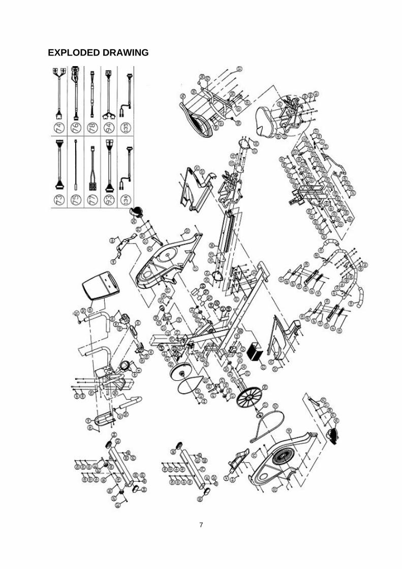
EXPLODED DRAWING
8
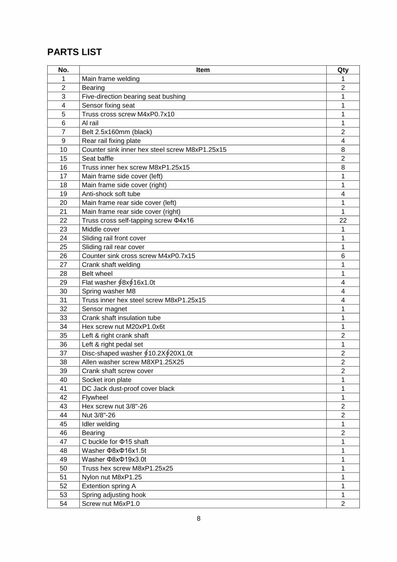
PARTS LIST
No. Item Qty
1 Main frame welding 1
2 Bearing 2
3 Five-direction bearing seat bushing 1
4 Sensor fixing seat 1
5 Truss cross screw M4xP0.7x10 1
6 Al rail 1
7 Belt 2.5x160mm (black) 2
9 Rear rail fixing plate 4
10 Counter sink inner hex steel screw M8xP1.25x15 8
15 Seat baffle 2
16 Truss inner hex screw M8xP1.25x15 8
17 Main frame side cover (left) 1
18 Main frame side cover (right) 1
19 Anti-shock soft tube 4
20 Main frame rear side cover (left) 1
21 Main frame rear side cover (right) 1
22 Truss cross self-tapping screw Φ4x16 22
23 Middle cover 1
24 Sliding rail front cover 1
25 Sliding rail rear cover 1
26 Counter sink cross screw M4xP0.7x15 6
27 Crank shaft welding 1
28 Belt wheel 1
29 Flat washer ∮8x∮16x1.0t 4
30 Spring washer M8 4
31 Truss inner hex steel screw M8xP1.25x15 4
32 Sensor magnet 1
33 Crank shaft insulation tube 1
34 Hex screw nut M20xP1.0x6t 1
35 Left & right crank shaft 2
36 Left & right pedal set 1
37 Disc-shaped washer ∮10.2X∮20X1.0t 2
38 Allen washer screw M8XP1.25X25 2
39 Crank shaft screw cover 2
40 Socket iron plate 1
41 DC Jack dust-proof cover black 1
42 Flywheel 1
43 Hex screw nut 3/8"-26 2
44 Nut 3/8"-26 2
45 Idler welding 1
46 Bearing 2
47 C buckle for Φ15 shaft 1
48 Washer Φ8xΦ16x1.5t 1
49 Washer Φ8xΦ19x3.0t 1
50 Truss hex screw M8xP1.25x25 1
51 Nylon nut M8xP1.25 1
52 Extention spring A 1
53 Spring adjusting hook 1
54 Screw nut M6xP1.0 2

9
55 Belt -52"x6 groove 1
56 Small dynamo fixing iron slice 1
57 Truss philips screw M4xP0.7x10 4
58 Dynamo 1
60 Washer Φ6xΦ19x1.5t 1
61 Truss philips screw M6xP1.0x12 1
62 Belt 350" J2 1
63 Small motor 1
64 Cable 1
65 Nylon nut M5xP0.8 4
66 Truss philips screw M5xP0.8x40 4
67 EMS lower controller 1
68 Truss cross screwM4xP0.7x10 2
69 Battery 6V 2.3Ah 1
70 Buckle-F 38X50 1
71 Buckle-M 38X50 1
72 Belt 2.5x160mm (black) 5
73 Control wire (lower) 1
74 Grinding wheel control wire 1
75 Speed sensor wire 1
76 Power supply wire 1
77 Battery power wire 1
78 Wire grip power wire 1
79 Rear stabalizer tube welding 1
80 Arc tube oval 50x100x2.0t 2
81 Hex screw nut M8xP1.25 2
82 Adjusting feet pad M8X25mm 2
83 Front stabalizer tube welding 1
84 Arc tube oval 50x100x2.0t 2
85 Rolling wheel #032 2
86 Nylon nut M8xP1.25 2
87 Truss inner hex screw M8xP1.25x40 2
88 Hex screw nut M8xP1.25 2
89 Adjusting feet pad M8X25mm 2
90 Control tube welding 1
91 Mushroom end cap -Φ1-1/4" 2
92 HDR foam inner dia ∮28x3tx400mm 2
93 Control wire middle 1
94 Hand grip fast connection wire 1
95 Back pad fixing tube welding 1
96 Back pad 1
97 Truss cross self-tapping screw Φ4x20 6
98 Flat tube inner cap φ1-1/8" X1.5t 4
99 Seat welding 1
100 Rolling wheel bushing 4
101 POM rolling wheel 6
Bearing 6
103 Rolling shaft 2
104 Nylon nut M12xP1.75 2
105 Allen screw M8xP1.25x35 4
106 Washer Φ8xΦ16x1.5t 8
107 Nylon nut M8xP1.25 6

10
108 Adjusting shaft 1
109 Seat brake block set 1
110 Washer ψ5xψ12x1.0t 1
111 Pressing head cross screw M4xP0.7x8 1
112 Adjusting ring bushing 1
113 Adjusting handle bar welding dipping PU 1
114 Nylon nut M12xP1.75 1
115 Wire fixing knob UC-0.5 1
116 Truss cross screw M4xP0.7x10 1
117 Extention spring 1
118 Washer Φ6xΦ19x1.5t 1
119 Truss inner hex screw M6xP1.0x15 1
120 Copper bushing 1
121 Washer Φ8xΦ20x1.5t 1
122 Spring washer M8 1
123 Truss inner hex steel screw M8xP1.25x15 1
124 Handrail welding 1
125 Hand grip heart pulse cover (long) 2
Heart pulse sensor plate B nake board stainless steel 2
127 Hand grip heart pulse cover (short) 2
Heart pulse sensor plate A nake board stainless steel 2
129 Membrane handrail key transform board 2
130 Round head cross self-tapping screw Φ2x6 2
131 Counter sink cross screw M3xP0.5x25 4
132 Membrane key - left 2-key <STOP&START> 1
133 Membrane key - right 2-key <LEVEL> 1
134 Hand grip fast key connection wire (lower) left 1
135 Hand grip fast key connection wire (lower) right 1
136 HDR foam inner dia ∮27x5tx245mm 2
137 TPR handle bar 2
138 Counter sink inner hex steel screw M4xP0.7x8 2
139 Computer console set (led) 1
139-1 TPR computer console book shelf 1
139-2 ABS computer console book shelf 1
139-3 Comouter console lower cover 1
139-4 Truss cross self-tapping screw Φ4x12 11
139-5 Computer console upper cover 1
139-6 Panel decal-LED 1
139-7 Membrane key 1
139-8 Key decal 1
139-9 Membrane key connection wire 1
139-10 EVA anti-slip pad 2
139-11 Bugle 2
139-14 Mult-media board 1
139-15 RJ45 dust-proof cap black 2
139-16 USB dust-proof cap black 1
139-17 Round head cross self-tapping screw Φ3x8 12
139-18 Wire fixng knob 1
139-19 Truss cross self-tapping screw Φ4x12 1
139-21 Upper control board 1
139-22 Round head cross self-tapping screw Φ2x6 6
139-23 Wireless heart receiver 1

11
139-24 Wireless heart board connection wire 1
139-25 Mult-media board connection wire 1
139-26 Control wire (upper) 1
139-27 Hand grip fast key connection wire (upper) 1
140 Computer console lower decoration cover 1
141 Computer console front decoration cover (left) 1
142 Computer console front decoration cover (right) 1
143 Stuff bottle shelf 1
144 Bottle shelf 1
145 Control tube decoration cover (left) 1
146 Control tube decoration cover (right) 1
147 Truss cross screw M4xP0.7x12 2
148 Washer ∮8x∮12x1.0t 4
149 CKS inner hex screw M8XP1.25X20 4
150 Truss cross screw M5xP0.8x12 2
151 Truss cross screw M5xP0.8x10 4
152 Truss cross self-tapping screw Φ4x20 2
153 Truss cross self-tapping screw Φ4x10 3
154 Washer Φ8xΦ16x1.5t 4
155 Spring washer M8 4
156 Truss inner hex screw M8xP1.25x20 4
157 Washer Φ8xΦ16x1.5t 8
158 Nylon nut M8xP1.25 4
159 Truss inner hex screw M8xP1.25x40 4
160 Flat washer ∮8x∮16x1.0t 8
161 Nylon nut M8xP1.25 4
162 Spring washer M8 4
163 CKS inner hex screw M8XP1.25X20 4
164 Truss cross self-tapping screw Φ4x16 4
165 Flat washer ∮8x∮16x1.0t 4
166 Spring washer M8 4
167 Truss inner hex screw M8xP1.25x20 4
168 L-shaped wrench+cross opener 6x40x120mm 1
169 Opener wrench 13mm+15mm 1
170 L-shaped hex wrench+cross opener 5mmx40mmx180mm 1
171 Power supplier DC 7.5V / 2.5A 1
172 Power wire 1
190 Seat pad 1
192 Iron hex rivet nuts 4
12
ASSEMBLY STEPS
To assemble this device correctly, follow these steps:
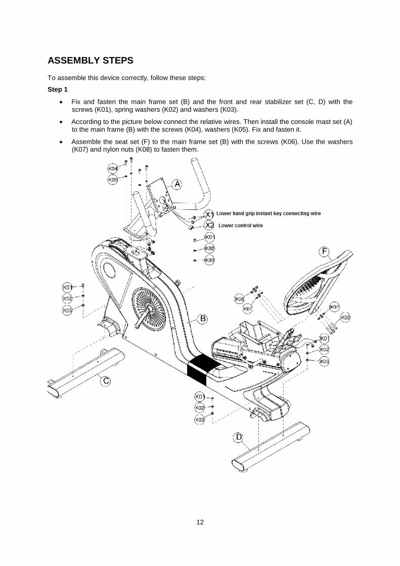
Step 1
Fix and fasten the main frame set (B) and the front and rear stabilizer set (C, D) with the screws (K01), spring washers (K02) and washers (K03).
According to the picture below connect the relative wires. Then install the console mast set (A) to the main frame (B) with the screws (K04), washers (K05). Fix and fasten it.
Assemble the seat set (F) to the main frame set (B) with the screws (K06). Use the washers (K07) and nylon nuts (K08) to fasten them.

13
Step 2
According to the picture connect the relative wires.
Thereafter lock the handrail set (E) to the main frame set (B) with the screws (K09), washers (K10 and K11) and nylon nuts (K12). Don’t fasten them too tightly.
Plug the rest wires into the main frame set and fasten tightly the screws (K09), washers (K10 and K11) and nylon nuts (K12).
If you have done all previous steps you can fasten the seat (G) to the main frame set with the screws (K13), washers (K14 and K15) as shown below.
Fasten the console mast decoration cover (H) to the main frame with the screws (K16).
Install the left and right pedals (I). Please, distinguish the left one and the right one. You can find the signs “L” and “R” at the pedal bottom.
14
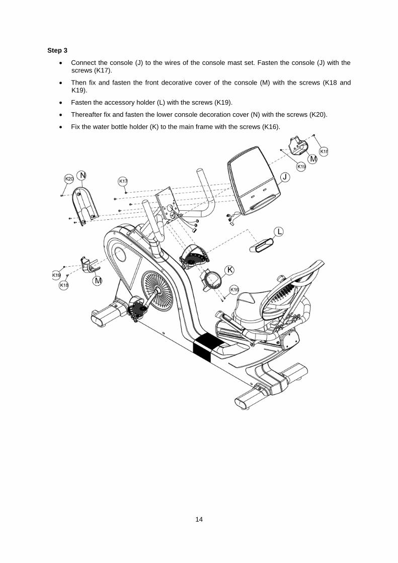
Step 3
Connect the console (J) to the wires of the console mast set. Fasten the console (J) with the screws (K17).
Then fix and fasten the front decorative cover of the console (M) with the screws (K18 and K19).
Fasten the accessory holder (L) with the screws (K19).
Thereafter fix and fasten the lower console decoration cover (N) with the screws (K20).
Fix the water bottle holder (K) to the main frame with the screws (K16).
15
CONSOLE OPERATION INSTRUCTIONS
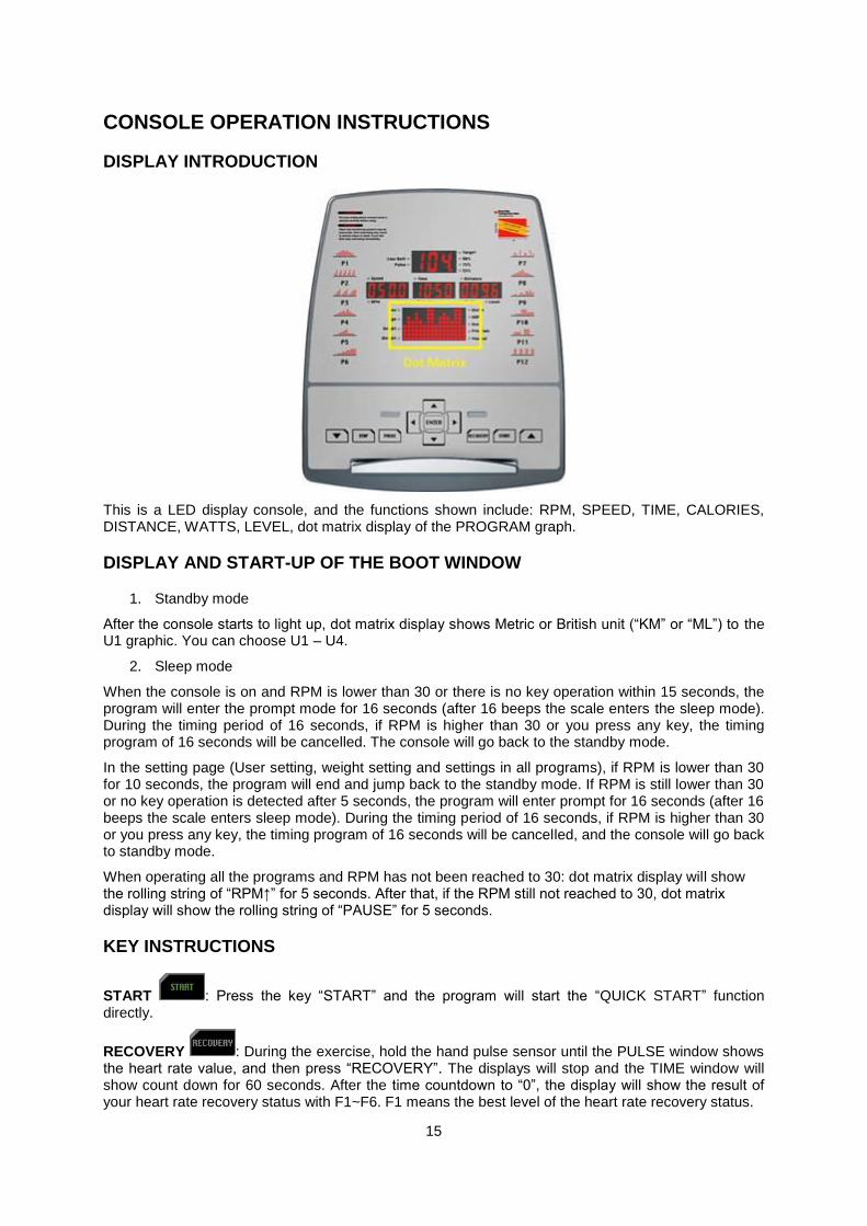
DISPLAY INTRODUCTION
This is a LED display console, and the functions shown include: RPM, SPEED, TIME, CALORIES, DISTANCE, WATTS, LEVEL, dot matrix display of the PROGRAM graph.
DISPLAY AND START-UP OF THE BOOT WINDOW
1. Standby mode
After the console starts to light up, dot matrix display shows Metric or British unit (“KM” or “ML”) to the U1 graphic. You can choose U1 – U4.
2. Sleep mode
When the console is on and RPM is lower than 30 or there is no key operation within 15 seconds, the program will enter the prompt mode for 16 seconds (after 16 beeps the scale enters the sleep mode). During the timing period of 16 seconds, if RPM is higher than 30 or you press any key, the timing program of 16 seconds will be cancelled. The console will go back to the standby mode.
In the setting page (User setting, weight setting and settings in all programs), if RPM is lower than 30 for 10 seconds, the program will end and jump back to the standby mode. If RPM is still lower than 30 or no key operation is detected after 5 seconds, the program will enter prompt for 16 seconds (after 16 beeps the scale enters sleep mode). During the timing period of 16 seconds, if RPM is higher than 30 or you press any key, the timing program of 16 seconds will be cancelled, and the console will go back to standby mode.
When operating all the programs and RPM has not been reached to 30: dot matrix display will show the rolling string of “RPM↑” for 5 seconds. After that, if the RPM still not reached to 30, dot matrix display will show the rolling string of “PAUSE” for 5 seconds.
KEY INSTRUCTIONS
START : Press the key “START” and the program will start the “QUICK START” function directly.
RECOVERY : During the exercise, hold the hand pulse sensor until the PULSE window shows the heart rate value, and then press “RECOVERY”. The displays will stop and the TIME window will show count down for 60 seconds. After the time countdown to “0”, the display will show the result of your heart rate recovery status with F1~F6. F1 means the best level of the heart rate recovery status.

16
PAUSE : If you press this button while exercising, the program will immediately operate the “PAUSE” operation. If you press it during the program setting you can go back to the program selected page and rework it.
STOP : Press the “STOP” key to stop it. You can use “ENTER” key to switch the display screen in this order: “SPEED - TIME – DISTANCE / RPM - CALORIES - WATTS”.
ENTER : Press this button during program setting to confirm it and to go to the next page.
DIRECTION , , , , , : Using these buttons you can increase or decrease various values (WEIGHT, HEIGHT, AGE, SEX, PULSE, TIME…), functional modes (WATT, HRP, USER, PROGRAM, MANUAL. You also can increase or decrease the resistance.
PROGRAM FUNCTION
Program mode: PROGRAMS P1~P12
1. Press the direction keys to select P1P12 PROGRAM.
2. Press Enter to get into the target value setting page.
3. Thereafter press “ENTER”, the TIME indicator lights up and the LED indicator light shines on the display of “TIME”. The initial value of “TIME” is “0:00”. Press direction keys to set the “TIME”.
4. After the “TIME” setting press “ENTER”, the DISTANCE indicator lights up and the LED indicator light shines on the display of “DISTANCE”. The initial value of “DISTANCE” is “0.0”. Press direction keys to set the “DISTANCE”.
5. After the “DISTANCE” setting press “ENTER” and the CALORIES indicator lights up and the LED indicator light shines on the display of “CALORIES”. The initial value of “CALORIES” is “0”. Press direction keys to set the “CALORIES”.
6. The TIME – DISTANCE – CALORIES can be set as a cycle setting. After the target values of TIME, DISTANCE and CALORIES have been set in, press the key “START”. The mode starts to operate.
If you press “ENTER” during exercising, you can switch and fix the display screen in this order: “SPEED - TIME – DISTANCE / RPM - CALORIES - WATTS”.
Press the “PAUSE” button during exercising and the program will pause. The TIME/DISTANCE/CALORIES display will show motion data by turns. If you want to continue the previous exercising (after the pause), press “START” and the program will continue with the time, distance and calories data as they were before the pause.
Press “STOP” and you will stop the program. Press it again and you will clean the exercise data and will go back to the main program selecting page for MANUAL/PROGRAM/USER/HRC/WATTS.
Dot matrix displayed messages during exercising:
If the RPM of 30 (during exercising) has not been reached, the screen displays twice a rolling string of “RPM↑” for 5 seconds. After this message, if the RPM still has not the required value (30), there will appear twice the rolling string of “PAUSE” on the screen (for 5 seconds).
Manual mode
1. Press the direction keys to select “MANUAL”.
2. Press “ENTER” to get into the target value setting page.
3. Thereafter press “ENTER”, the TIME indicator lights up and the LED indicator light shines on the display of “TIME”. The initial value of “TIME” is “0:00”. Press direction keys to set “TIME”.
4. After the setting of TIME, press “ENTER”, the DISTANCE indicator lights up and the LED indicator light shines on the display of “DISTANCE”. The initial value of “DISTANCE” is “0.0”. Press direction keys to set “DISTANCE”.
17
5. After the setting of “DISTANCE”, press “ENTER” key, the CALORIES indicator lights up and the LED indicator light shines on the display of “CALORIES”. The initial value of “CALORIES” is “0”. Press direction keys to set “CALORIES”.
6. The TIME – DISTANCE – CALORIES can be set as a cycle. After the target values of TIME, DISTANCE and CALORIES have been set in, press the key “START”. The mode starts to operate.
If you press “ENTER” during exercising, you can switch and fix the display screen in this order: “SPEED - TIME – DISTANCE / RPM - CALORIES - WATTS”.
Press the “PAUSE” button during exercising and the program will pause. The TIME/DISTANCE/CALORIES display will show motion data by turns. If you want to continue the previous exercising (after the pause), press “START” and the program will continue with the time, distance and calories data as they were before the pause.
Press “STOP” and you will stop the program. Press it again and you will clean the exercise data and will go back to the main program selecting page for MANUAL/PROGRAM/USER/HRC/WATTS.
Dot matrix displayed messages during exercising:
If the RPM of 30 (during exercising) has not been reached, the screen displays twice a rolling string of “RPM↑” for 5 seconds. After this message, if the RPM still has not the required value (30), there will appear twice the rolling string of “PAUSE” on the screen (for 5 seconds).
User mode
1. Press the direction keys to select “USER”.
2. Press “ENTER” to get into the target value setting page.
3. After pressing “ENTER”, the TIME indicator lights up and the LED indicator light shines on the display of “TIME”. The initial value of “TIME” is “0:00”. Press direction keys to set “TIME”.
4. After the setting of “TIME”, press “ENTER”, the DISTANCE indicator lights up and the LED indicator light shines on the display of “DISTANCE”. The initial value of “DISTANCE” is “0.0”. Press direction keys to set “DISTANCE”.
5. After the setting of “DISTANCE”, press “ENTER”, the CALORIES indicator lights up and the LED indicator light shines on the display of “CALORIES”. The initial value of “CALORIES” is “0”. Press direction keys to set “CALORIES”.
6. The TIME – DISTANCE – CALORIES can be set as a cycle. After the target values of TIME, DISTANCE and CALORIES have been set in, press the key “START”. The mode starts to operate.
If the user wants to do the operating program of graphical editing:
1. Enter into “USER” program, the TIME indicator lights up and the LED indicator light shines on the display of “TIME”. The initial value of “TIME” is “0:00”.
2. For editing of graphs, press “ENTER” for 3 seconds, then the first row on the Dot Matrix flicked. At the TIME display chart will show code S-1 to show the editing.
3. Press DIRECTION keys to set the “LEVEL”. After complete setting is confirmed, press “ENTER” to set program of LEVEL on the next row.
4. When entering the LEVEL setting but failed on setting, the user can press “ENTER” and convert to the next operation setting program. There are “S-1 ~ S-16” locations in total, which can be set in. After the setting of those locations, the machine converts to the setting program of “TIME” for operation.
If you press “ENTER” during exercising, you can switch and fix the display screen in this order: “SPEED - TIME – DISTANCE / RPM - CALORIES - WATTS”.
Press the “PAUSE” button during exercising and the program will pause. The TIME/DISTANCE/CALORIES display will show motion data by turns. If you want to continue the previous exercising (after the pause), press “START” and the program will continue with the time, distance and calories data as they were before the pause.

18
Press “STOP” and you will stop the program. Press it again and you will clean the exercise data and will go back to the main program selecting page for MANUAL/PROGRAM/USER/HRC/WATTS.
Dot matrix displayed messages during exercising:
If the RPM of 30 (during exercising) has not been reached, the screen displays twice a rolling string of “RPM↑” for 5 seconds. After this message, if the RPM still has not the required value (30), there will appear twice the rolling string of “PAUSE” on the screen (for 5 seconds).
HRP mode
1 Press the direction keys to select “HRP”.
2 Press “ENTER” to get into the target value setting page.
3 After pressing “ENTER”, the “HEIGHT” indicator lights up and the Dot Matrix display will show “HEIGHT”. The initial value of “HEIGHT” is “170”. Press direction keys to set the “HEIGHT”.
4 After the setting of HEIGHT, press “ENTER”, the “AGE” indicator lights up and the Dot Matrix display will show “AGE”. The initial value of “AGE” is “30”. Press direction keys to set the “AGE”.
5 After the setting of AGE, press “ENTER”, the “SEX” indicator lights up and the Dot Matrix display will show “GENDER”. The initial value of “SEX” is “M” as male and “F” as female. Press direction keys to set the “SEX”.
6 After the setting of SEX, press “ENTER”, the “TARGET, 90%, 75%, 55%” indicator lights up and at “PULSE” display will show the initial value. Press the direction keys to select the target. TARGET could allow user to set the target heart rate value with the direction keys. The initial value of 90%, 75% and 55% depends on the HEIGHT, AGE and SEX setting.
7 After the complete setting of “PULSE”, press “ENTER”, the TIME indicator lights up and the LED indicator light shines on the display of “TIME”. The initial value of “TIME” is “0:00”. Press direction keys to set “TIME”.
8 After the setting of “TIME”, press “ENTER”, the DISTANCE indicator lights up and the LED indicator light shines on the display of “DISTANCE”. The initial value of “DISTANCE” is “0.0”. Press direction keys to set the “DISTANCE”.
9 After the setting of “DISTANCE”, press “ENTER”, the CALORIES indicator lights up and the LED indicator light shines on the display of “CALORIES”. The initial value of “CALORIES” is “0”. Press direction keys to set the “CALORIES”.
10 The TIME – DISTANCE – CALORIES can be set as a cycle. After the target values of TIME, DISTANCE and CALORIES have been set in, press the key “START”. The mode starts to operate.
If you press “ENTER” during exercising, you can switch and fix the display screen in this order: “SPEED - TIME – DISTANCE / RPM - CALORIES - WATTS”.
Press the “PAUSE” button during exercising and the program will pause. The TIME/DISTANCE/CALORIES display will show motion data by turns. If you want to continue the previous exercising (after the pause), press “START” and the program will continue with the time, distance and calories data as they were before the pause.
Press “STOP” and you will stop the program. Press it again and you will clean the exercise data and will go back to the main program selecting page for MANUAL/PROGRAM/USER/HRC/WATTS.
A) Operation of “WARM-UP” function
1) Resistance is preset at level 1, and “Heart Rate Control” function will automatically work after 1 minute.
2) Users can still use the direction keys to increase or reduce resistance.

19
B) Operating program of “HEART RATE CONTROL” function
1) In the program, comparison between “actual heart rate” and “preset heart rate (55% / 75% / 90% / TARGET)” will be conducted once each 10 seconds.
2) When the program fails to detect “actual heart rate”, then the program will be paused and resistance won’t be increased. The PULSE display will show “P”.
3) Users can also use the direction keys to increase or reduce the resistance.
4) When the “actual heart rate” is lower than the “preset heart rate” with 4, the program will automatically increase the resistance. Each time will increase for 1 level; the maximum will be increased to level 16.
5) When the “actual heart rate” is higher than the “preset heart rate” with 4, the program will automatically reduce the resistance. Each time will decrease for 1 level; the minimum will be decreased to level 1.
6) When the actual heart rate reaches the preset heart rate for consecutive 3 minutes, or when the preset time is over, the program will automatically stop the “Heart Rate Control” function, and enter into the “COOL DOWN” phase.
C) “COOL DOWN” for 1 min. after the “Heart rate control”
1) When the “1-minute COOL DOWN” function starts, the program makes a long sound of “beep”, and the Dot Matrix display will show “COOL”. The TIME display will start counting down (1 min.).
2) In the COOL DOWN function the resistance will be on the level 1. All data will be taken and used as a continuation from previous “Heart rate control” function.
3) In this COOL DOWN function you can only use “STOP/ RESET” key.
Watts mode
1 Press the direction keys to select “WATTS”.
2 Press “ENTER” to get into the target value setting page.
3 After pressing “ENTER”, the WATTS indicator lights up and the LED indicator light shines on the display of “WATTS”. The initial value of “WATTS” is “120”. Press direction keys to set “WATTS”.
4 After the setting of WATTS, press “ENTER”, the TIME indicator lights up and the LED indicator light shines on the display of “TIME”. The initial value of “TIME” is “0:00”. Press direction keys to set the “TIME”.
5 After the setting of “TIME”, press “ENTER”, the DISTANCE indicator lights up and the LED indicator light shines on the display of “DISTANCE”. The initial value of “DISTANCE” is “0.0”. Press direction keys to set “DISTANCE”.
6 After the setting of “DISTANCE”, press “ENTER”, the CALORIES indicator lights up and the LED indicator light shines on the display of “CALORIES”. The initial value of “CALORIES” is “0”. Press direction keys to set “CALORIES”.
7 The TIME – DISTANCE – CALORIES can be cycle setting. After the target settings of TIME, DISTANCE and CALORIES are determined, press the key “START”, and this mode starts to operate.
If you press “ENTER” during exercising, you can switch and fix the display screen in this order: “SPEED - TIME – DISTANCE / RPM - CALORIES - WATTS”.
Press the “PAUSE” button during exercising and the program will pause. The TIME/DISTANCE/CALORIES display will show motion data by turns. If you want to continue the previous exercising (after the pause), press “START” and the program will continue with the time, distance and calories data as they were before the pause.
Press “STOP” and you will stop the program. Press it again and you will clean the exercise data and will go back to the main program selecting page for MANUAL/PROGRAM/USER/HRC/WATTS.

20
Dot matrix displayed messages during exercising:
If the RPM of 30 (during exercising) has not been reached, the screen displays twice a rolling string of “RPM↑” for 5 seconds. After this message, if the RPM still has not the required value (30), there will appear twice the rolling string of “PAUSE” on the screen (for 5 seconds).
PROGRAM GRAPHS
Manual HRC WATT

21
TERMS AND CONDITIONS OF WARRANTY, WARRANTY CLAIMS
General Conditions of Warranty and Definition of Terms
All Warranty Conditions stated hereunder determine Warranty Coverage and Warranty Claim Procedure. Conditions of Warranty and Warranty Claims are governed by Act No. 40/1964 Coll. Civil Code, Act No. 513/1991 Coll., Commercial Code, and Act No. 634/1992 Coll., Consumer Protection Act, as amended, also in cases that are not specified by these Warranty rules.
The seller is SEVEN SPORT s.r.o. with its registered office in Borivojova Street 35/878, Prague 13000, Company Registration Number: 26847264, registered in the Trade Register at Regional Court in Prague, Section C, Insert No. 116888.
According to valid legal regulations it depends whether the Buyer is the End Customer or not.
“The Buyer who is the End Customer” or simply the “End Customer” is the legal entity that does not conclude and execute the Contract in order to run or promote his own trade or business activities.
“The Buyer who is not the End Customer” is a Businessman that buys Goods or uses services for the purpose of using the Goods or services for his own business activities. The Buyer conforms to the General Purchase Agreement and business conditions to the extent specified in the Commercial Code.
These Conditions of Warranty and Warranty Claims are an integral part of every Purchase Agreement made between the Seller and the Buyer. All Warranty Conditions are valid and binding, unless otherwise specified in the Purchase Agreement, in the Amendment to this Contract or in another written agreement.
Warranty Conditions
Warranty Period
The Seller provides the Buyer a 24 months Warranty for Goods Quality, unless otherwise specified in the Certificate of Warranty, Invoice, Bill of Delivery or other documents related to the Goods. The legal warranty period provided to the Consumer is not affected.
By the Warranty for Goods Quality, the Seller guarantees that the delivered Goods shall be, for a certain period of time, suitable for regular or contracted use, and that the Goods shall maintain its regular or contracted features.
The Warranty does not cover defects resulting from (if applicable):
User’s fault, i.e. product damage caused by unqualified repair work, improper assembly, insufficient insertion of seat post into frame, insufficient tightening of pedals and cranks
Improper maintenance
Mechanical damages
Regular use (e.g. wearing out of rubber and plastic parts, moving mechanisms, joints etc.)
Unavoidable event, natural disaster
Adjustments made by unqualified person
Improper maintenance, improper placement, damages caused by low or high temperature, water, inappropriate pressure, shocks, intentional changes in design or construction etc.
Warranty Claim Procedure
The Buyer is obliged to check the Goods delivered by the Seller immediately after taking the responsibility for the Goods and its damages, i.e. immediately after its delivery. The Buyer must check the Goods so that he discovers all the defects that can be discovered by such check.
When making a Warranty Claim the Buyer is obliged, on request of the Seller, to prove the purchase and validity of the claim by the Invoice or Bill of Delivery that includes the product’s serial number, or eventually by the documents without the serial number. If the Buyer does not prove the validity of the Warranty Claim by these documents, the Seller has the right to reject the Warranty Claim.

22
If the Buyer gives notice of a defect that is not covered by the Warranty (e.g. in the case that the Warranty Conditions were not fulfilled or in the case of reporting the defect by mistake etc.), the Seller is eligible to require a compensation for all the costs arising from the repair. The cost shall be calculated according to the valid price list of services and transport costs.
If the Seller finds out (by testing) that the product is not damaged, the Warranty Claim is not accepted. The Seller reserves the right to claim a compensation for costs arising from the false Warranty Claim.
In case the Buyer makes a claim about the Goods that is legally covered by the Warranty provided by the Seller, the Seller shall fix the reported defects by means of repair or by the exchange of the damaged part or product for a new one. Based on the agreement of the Buyer, the Seller has the right to exchange the defected Goods for a fully compatible Goods of the same or better technical characteristics. The Seller is entitled to choose the form of the Warranty Claim Procedures described in this paragraph.
The Seller shall settle the Warranty Claim within 30 days after the delivery of the defective Goods, unless a longer period has been agreed upon. The day when the repaired or exchanged Goods is handed over to the Buyer is considered to be the day of the Warranty Claim settlement. When the Seller is not able to settle the Warranty Claim within the agreed period due to the specific nature of the Goods defect, he and the Buyer shall make an agreement about an alternative solution. In case such agreement is not made, the Seller is obliged to provide the Buyer with a financial compensation in the form of a refund.
SEVEN SPORT s.r.o.
Registered Office: Borivojova 35/878, 130 00 Praha 3, Czech Republic
Headquarters: Delnicka 957, 749 01 Vitkov, Czech Republic
Warranty & Service Centre: Cermenska 486, 749 01 Vitkov, Czech Republic
CRN: 26847264
VAT ID: CZ26847264
Phone: +420 556 300 970
E-mail: [email protected]
Web: www.insportline.cz
SK
INSPORTLINE s.r.o.
Headquarters, Warranty & Service centre: Elektricna 6471, 911 01 Trencin, Slovakia
CRN: 36311723
VAT ID: SK2020177082
Phone: +421(0)326 526 701
E-mail: [email protected]
Web: www.insportline.sk
Date of Sale: Stamp and Signature of Seller: