Embed Size (px)
Citation preview
User Manual
ARK-DS220
OPS ION2-Based Digital Signage Platform

CopyrightThe documentation and the software included with this product are copyrighted 2011by Advantech Co., Ltd. All rights are reserved. Advantech Co., Ltd. reserves the rightto make improvements in the products described in this manual at any time withoutnotice. No part of this manual may be reproduced, copied, translated or transmittedin any form or by any means without the prior written permission of Advantech Co.,Ltd. Information provided in this manual is intended to be accurate and reliable. How-ever, Advantech Co., Ltd. assumes no responsibility for its use, nor for any infringe-ments of the rights of third parties, which may result from its use.
Part No. 2006S22000 Edition 1
Printed in Taiwan August 2011
ARK-DS220 User Manual ii

AcknowledgementsIntel and Pentium are trademarks of Intel Corporation.
Microsoft Windows and MS-DOS are registered trademarks of Microsoft Corp.
All other product names or trademarks are properties of their respective owners.
iii ARK-DS220 User Manual
Product Warranty (2 years)Advantech warrants to you, the original purchaser, that each of its products will befree from defects in materials and workmanship for two years from the date of pur-chase.
This warranty does not apply to any products which have been repaired or altered bypersons other than repair personnel authorized by Advantech, or which have beensubject to misuse, abuse, accident or improper installation. Advantech assumes noliability under the terms of this warranty as a consequence of such events.
Because of Advantech’s high quality-control standards and rigorous testing, most ofour customers never need to use our repair service. If an Advantech product is defec-tive, it will be repaired or replaced at no charge during the warranty period. For out-of-warranty repairs, you will be billed according to the cost of replacement materials,service time and freight. Please consult your dealer for more details.
If you think you have a defective product, follow these steps:
1. Collect all the information about the problem encountered. (For example, CPU speed, Advantech products used, other hardware and software used, etc.) Note anything abnormal and list any onscreen messages you get when the problem occurs.
2. Call your dealer and describe the problem. Please have your manual, product, and any helpful information readily available.
3. If your product is diagnosed as defective, obtain an RMA (return merchandise authorization) number from your dealer. This allows us to process your return more quickly.
4. Carefully pack the defective product, a fully-completed Repair and Replacement Order Card and a photocopy proof of purchase date (such as your sales receipt) in a shippable container. A product returned without proof of the purchase date is not eligible for warranty service.
5. Write the RMA number visibly on the outside of the package and ship it prepaid to your dealer.
ARK-DS220 User Manual iv
Declaration of Conformity
CE
This product has passed the CE test for environmental specifications. Test conditionsfor passing included the equipment being operated within an industrial enclosure. Inorder to protect the product from being damaged by ESD (Electrostatic Discharge)and EMI leakage, we strongly recommend the use of CE-compliant industrial enclo-sure products.
FCC Class A
Note: This equipment has been tested and found to comply with the limits for a ClassA digital device, pursuant to part 15 of the FCC Rules. These limits are designed toprovide reasonable protection against harmful interference when the equipment isoperated in a commercial environment. This equipment generates, uses, and canradiate radio frequency energy and, if not installed and used in accordance with theinstruction manual, may cause harmful interference to radio communications. Opera-tion of this equipment in a residential area is likely to cause harmful interference inwhich case the user will be required to correct the interference at his own expense.
v ARK-DS220 User Manual
Technical Support and Assistance1. Visit the Advantech website at http://support.advantech.com where you can find
the latest information about the product.2. Contact your distributor, sales representative, or Advantech's customer service
center for technical support if you need additional assistance. Please have the following information ready before you call:– Product name and serial number– Description of your peripheral attachments– Description of your software (operating system, version, application software,
etc.)– A complete description of the problem– The exact wording of any error messages
ARK-DS220 User Manual vi
Warnings, Cautions and Notes
Warning! Warnings indicate conditions, which if not observed, can cause personal injury!
Caution! Cautions are included to help you avoid damaging hardware or losing data. e.g.
There is a danger of a new battery exploding if it is incorrectly installed. Do not attempt to recharge, force open, or heat the battery. Replace the battery only with the same or equivalent type recommended by the man-ufacturer. Discard used batteries according to the manufacturer's instructions.
Note! Notes provide optional additional information.
vii ARK-DS220 User Manual

Document FeedbackTo assist us in making improvements to this manual, we would welcome commentsand constructive criticism. Please send all such - in writing to: [email protected]
ARK-DS220 User Manual viii
Packing ListBefore installation, please ensure the following items have been shipped:
1 x ARK-DS220 Unit 1 x Diver/Utility CD/Manual 1 x China RoHS 1 x Simplified Chinese User Manual for CCC
ix ARK-DS220 User Manual
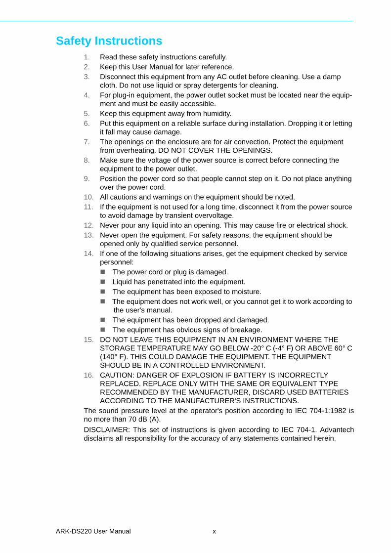
Safety Instructions1. Read these safety instructions carefully.2. Keep this User Manual for later reference.3. Disconnect this equipment from any AC outlet before cleaning. Use a damp
cloth. Do not use liquid or spray detergents for cleaning.4. For plug-in equipment, the power outlet socket must be located near the equip-
ment and must be easily accessible.5. Keep this equipment away from humidity.6. Put this equipment on a reliable surface during installation. Dropping it or letting
it fall may cause damage.7. The openings on the enclosure are for air convection. Protect the equipment
from overheating. DO NOT COVER THE OPENINGS.8. Make sure the voltage of the power source is correct before connecting the
equipment to the power outlet.9. Position the power cord so that people cannot step on it. Do not place anything
over the power cord.10. All cautions and warnings on the equipment should be noted.11. If the equipment is not used for a long time, disconnect it from the power source
to avoid damage by transient overvoltage.12. Never pour any liquid into an opening. This may cause fire or electrical shock.13. Never open the equipment. For safety reasons, the equipment should be
opened only by qualified service personnel.14. If one of the following situations arises, get the equipment checked by service
personnel:The power cord or plug is damaged.Liquid has penetrated into the equipment.The equipment has been exposed to moisture.The equipment does not work well, or you cannot get it to work according to
the user's manual.The equipment has been dropped and damaged.The equipment has obvious signs of breakage.
15. DO NOT LEAVE THIS EQUIPMENT IN AN ENVIRONMENT WHERE THE STORAGE TEMPERATURE MAY GO BELOW -20° C (-4° F) OR ABOVE 60° C (140° F). THIS COULD DAMAGE THE EQUIPMENT. THE EQUIPMENT SHOULD BE IN A CONTROLLED ENVIRONMENT.
16. CAUTION: DANGER OF EXPLOSION IF BATTERY IS INCORRECTLY REPLACED. REPLACE ONLY WITH THE SAME OR EQUIVALENT TYPE RECOMMENDED BY THE MANUFACTURER, DISCARD USED BATTERIES ACCORDING TO THE MANUFACTURER'S INSTRUCTIONS.
The sound pressure level at the operator's position according to IEC 704-1:1982 isno more than 70 dB (A).
DISCLAIMER: This set of instructions is given according to IEC 704-1. Advantechdisclaims all responsibility for the accuracy of any statements contained herein.
ARK-DS220 User Manual x

Safety Precaution - Static ElectricityFollow these simple precautions to protect yourself from harm and the products fromdamage.
To avoid electrical shock, always disconnect the power from your PC chassis before you work on it. Don't touch any components on the CPU card or other cards while the PC is on.
Disconnect power before making any configuration changes. The sudden rush of power as you connect a jumper or install a card may damage sensitive elec-tronic components.
xi ARK-DS220 User Manual

ARK-DS220 User Manual xii
Contents
Chapter 1 General Introduction ...........................11.1 Introduction ............................................................................................... 21.2 Product Features....................................................................................... 2
1.2.1 General ......................................................................................... 21.2.2 Display .......................................................................................... 21.2.3 Power Consumption...................................................................... 2
1.3 Hardware Specifications ........................................................................... 21.4 Mechanical Specifications......................................................................... 3
1.4.1 Dimensions ................................................................................... 3Figure 1.1 ARK-DS220 Mechanical Dimensions ......................... 3
1.4.2 Weight........................................................................................... 41.5 Power Requirements................................................................................. 4
1.5.1 System Power............................................................................... 41.5.2 RTC Battery .................................................................................. 4
1.6 Environmental Specifications .................................................................... 41.6.1 Operating Temperature................................................................. 41.6.2 Relative Humidity .......................................................................... 41.6.3 Storage Temperature.................................................................... 41.6.4 Vibration Loading During Operation.............................................. 41.6.5 Shock During Operation................................................................ 41.6.6 Safety............................................................................................ 41.6.7 EMC.............................................................................................. 4
Chapter 2 Hardware Installation ..........................52.1 ARK-DS220 I/O Connectors ..................................................................... 6
Figure 2.1 ARK-DS220 I/O connectors........................................ 62.2 ARK-DS220 Front Side External I/O Connectors...................................... 6
2.2.1 Power ON/OFF Button.................................................................. 6Figure 2.2 Power ON/OFF Button ............................................... 6
2.2.2 COM Connector ............................................................................ 6Figure 2.3 COM Connector.......................................................... 6Table 2.1: COM Connector Pin Assignments.............................. 7
2.2.3 USB 1~2 Connectors .................................................................... 7Figure 2.4 USB 1~2 Connectors.................................................. 7Table 2.2: USB 1~2 Connectors Pin Assignments...................... 7
2.2.4 Ethernet Connector (LAN) ............................................................ 7Figure 2.5 Ethernet Connector .................................................... 7Table 2.3: LAN Connector Pin Assignments ............................... 8
2.2.5 VGA Connector............................................................................. 8Figure 2.6 VGA Connector .......................................................... 8Table 2.4: VGA Connector Pin Assignments............................... 8
2.2.6 Audio Connector ........................................................................... 9Figure 2.7 Line-out and MIC Connector ...................................... 9
2.3 JAE TX-25 Plug Connector ....................................................................... 9Figure 2.8 JAE TX-25 Plug Connector ........................................ 9Table 2.5: JAE TX-25 Plug Connector Pin Assignments............. 9
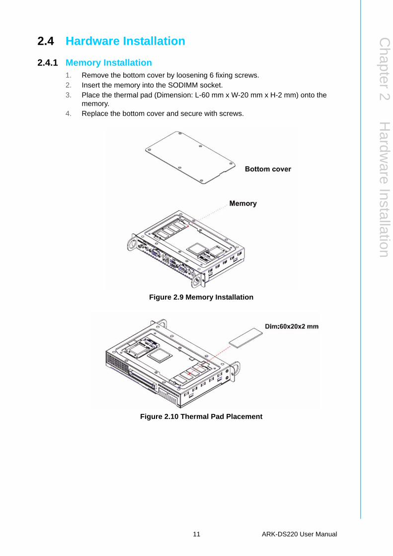
2.4 Hardware Installation .............................................................................. 112.4.1 Memory Installation..................................................................... 11
Figure 2.9 Memory Installation .................................................. 11Figure 2.10Thermal Pad Placement ........................................... 11
2.4.2 HDD Installation .......................................................................... 12Figure 2.11Assembly HDD module ............................................ 12Figure 2.12HDD Installation........................................................ 12
xiii ARK-DS220 User Manual
Chapter 3 BIOS Settings .................................... 133.1 BIOS Introduction.................................................................................... 143.2 Entering BIOS Setup............................................................................... 14
Figure 3.1 Setup Program Initial Screen ................................... 143.2.1 Main Setup.................................................................................. 15
Figure 3.2 Main Setup Screen................................................... 153.2.2 Advanced BIOS Features Setup................................................. 16
Figure 3.3 Advanced BIOS Features Setup Screen.................. 16Figure 3.4 CPU Configuration Settings ..................................... 17Figure 3.5 IDE Configuration ..................................................... 18Figure 3.6 AHCI Configuration .................................................. 19Figure 3.7 Super I/O Chipset Configuration .............................. 20Figure 3.8 Hardware Health Configuration ................................ 21Figure 3.9 ACPI Settings ........................................................... 22Figure 3.10General ACPI Configuration..................................... 22Figure 3.11Advanced ACPI Configuration.................................. 23Figure 3.12Chipset ACPI Configuration ..................................... 24Figure 3.13APM Configuration ................................................... 25Figure 3.14USB Configuration.................................................... 26
3.2.3 PCI/PnP Configurations.............................................................. 27Figure 3.15PCI/PnP Setup (Top)................................................ 27
3.2.4 Boot Settings .............................................................................. 28Figure 3.16Boot Setup Utility...................................................... 28Figure 3.17Boot Settings Configuration...................................... 29Figure 3.18BIOS Setup Boot Device Priority.............................. 30Figure 3.19BIOS Setup Hard Disk Drives .................................. 31
3.2.5 Security Setup ............................................................................ 32Figure 3.20Password Configuration ........................................... 32
3.2.6 Advanced Chipset Configurations .............................................. 33Figure 3.21Advanced Chipset Settings ...................................... 33Figure 3.22North Bridge Chipset Configuration.......................... 33Figure 3.23South Bridge Chipset Configuration ......................... 34
3.2.7 Exit Options ................................................................................ 35Figure 3.24Exit Options .............................................................. 35
Chapter 4 Software Installation......................... 374.1 Driver Installation .................................................................................... 38
4.1.1 Chipset Driver Installation........................................................... 384.1.2 Graphic Driver Installation .......................................................... 414.1.3 LAN Driver Installation ................................................................ 434.1.4 Audio Driver Installation.............................................................. 46
ARK-DS220 User Manual xiv
Chapter 1
1 General IntroductionThis chapter gives background information on ARK-DS220 series.
1.1 IntroductionThe ARK-DS220 complies with Intel OPS (Open Pluggable Specification) standardand is powered by an Intel Atom D525 dual-core processor (fan-based) and IntelAtom N455 single-core processor (fanless) with integrated NVIDIA GT218 (ION2)graphic module for Full HD playback. Compliant with the Open Pluggable Specifica-tion (OPS), its slot-in module design effectively lowers deployment and field mainte-nance costs to simplify device installation, usage, maintenance and upgrades.
ARK-DS220 OPS media player enables digital signage manufacturers to deploy sys-tems faster, with lower costs for development and implementation. Its slot-in moduleis connected via a JAE 80-pin connector, and includes the HDMI, DVI-D, DP, UART,and USB2.0 signals. The player-screen communication interface via UART andHDMI CEC provides status reporting and control, and also supports digital audio/video signals via HDMI or display port, for picture-perfect content reproduction. ARK-DS220 also supports 1x GigaLAN, 1x COM ports, and 2x USB2.0 ports giving a greatselection for data communication in display applications. The entire design makesdigital signage applications more intelligent and connected.
1.2 Product Features
1.2.1 General Integrated NVIDIA GT218 (ION2) graphic module for Full HD playback Designed compliant with OPS (Open Pluggable Standard) Embedded Intel® Atom™ D525 dual-core (fan-based) or Intel® Atom™ N455
single-core processor (fanless) Supports HDMI, DP, UART, and USB2.0 via JAE 80-pin connector Slot-in integration, easy maintenance
1.2.2 Display Support up to 1920 x 1080 (via OPS interconnection) video playback perfor-
mance (subject to the video media format and playback software)
1.2.3 Power Consumption Typical: 18 W (CPU is Intel Atom D525 1.8 GHz) Max.: 30 W (CPU is Intel Atom D525 1.8 GHz)
1.3 Hardware Specifications CPU: Intel Atom D525 1.8 GHz (or Intel Atom N455 1.66 GHz) System Chipset: Intel Atom D525/N455 + ICH8M Graphic Chipset: nVidia GT218-ILV-B1 Video Memory Size: Independent display memory 512 MB BIOS: AMI 16 Mbit Flash BIOS System Memory: 1 x DDR3 204-pin SODIMM sockets, supports up to 4 GB (w/
D525); or 2 GB (w/ N455) HDD: Supports 1 x 2.5" SATA HDD (max 9.5mm height) Watchdog Timer: Single chip watchdog 255-level interval timer, setup by soft-
ware
ARK-DS220 User Manual 2
Chapter 1
GeneralIntroduction
I/O Interface:– 1 x JAE TX25-80P-LT-H1E Plug– 1 x HDMI (via OPS interconnection)– 1x Display Port (via OPS interconnection)– 1 x VGA (D-sub 15-pin)– 2 x USB 2.0 compliant ports– 2 audio phone jacks for Mic-in, Line-out– 1 x COM (RS-232)– 1 x MiniPCIe (Internal)
Ethernet Chipset: 1 x Intel 82567V– Speed: 10/100/1000 Mbps– Interface: 1 x RJ-45 jacks with LED– Standard: IEEE 802.3z/ab (1000 Base-T) or IEEE 802.3u 100 Base-T compli-
ant Resolution:
– HDMI/DP: up to 1920 x 1080 (via OPS interconnection)– VGA: up to 2048 x 1536 @ 60 Hz
1.4 Mechanical Specifications
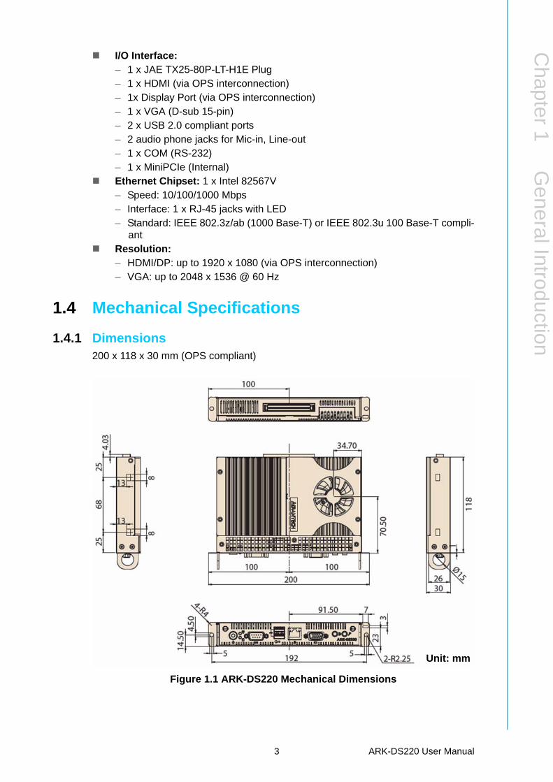
1.4.1 Dimensions200 x 118 x 30 mm (OPS compliant)
Figure 1.1 ARK-DS220 Mechanical Dimensions
Unit: mm
3 ARK-DS220 User Manual
1.4.2 Weight1.5 kg (3.3 lb)
1.5 Power Requirements
1.5.1 System Power12 V ~ 24 V DC-in (via OPS interconnection)
1.5.2 RTC Battery3 V/190 mAH BR2032L
1.6 Environmental Specifications
1.6.1 Operating Temperature0° C ~ 40° C (32 ~104° F)
1.6.2 Relative Humidity95% @ 40° C (non-condensing)
1.6.3 Storage Temperature-20 ~ 70° C (-4 ~ 158° F)
1.6.4 Vibration Loading During Operation0.5 Grms, IEC 60068-2-64, random, 5 ~ 500 Hz, 1 Oct./min, 1 hr./axis.
1.6.5 Shock During Operation20 G, IEC 60068-2-27, half sine, 11 ms duration
1.6.6 SafetyUL, BSMI, CCC
1.6.7 EMCCE, FCC, BSMI
ARK-DS220 User Manual 4
Chapter 2
2 Hardware InstallationThis chapter introduces external I/O and the installation of ARK-DS220 Hardware.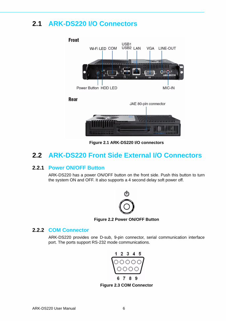
2.1 ARK-DS220 I/O Connectors
Figure 2.1 ARK-DS220 I/O connectors
2.2 ARK-DS220 Front Side External I/O Connectors
2.2.1 Power ON/OFF ButtonARK-DS220 has a power ON/OFF button on the front side. Push this button to turnthe system ON and OFF. It also supports a 4 second delay soft power off.
Figure 2.2 Power ON/OFF Button
2.2.2 COM ConnectorARK-DS220 provides one D-sub, 9-pin connector, serial communication interfaceport. The ports support RS-232 mode communications.
Figure 2.3 COM Connector
ARK-DS220 User Manual 6
Chapter 2
Hardw
areInstallation
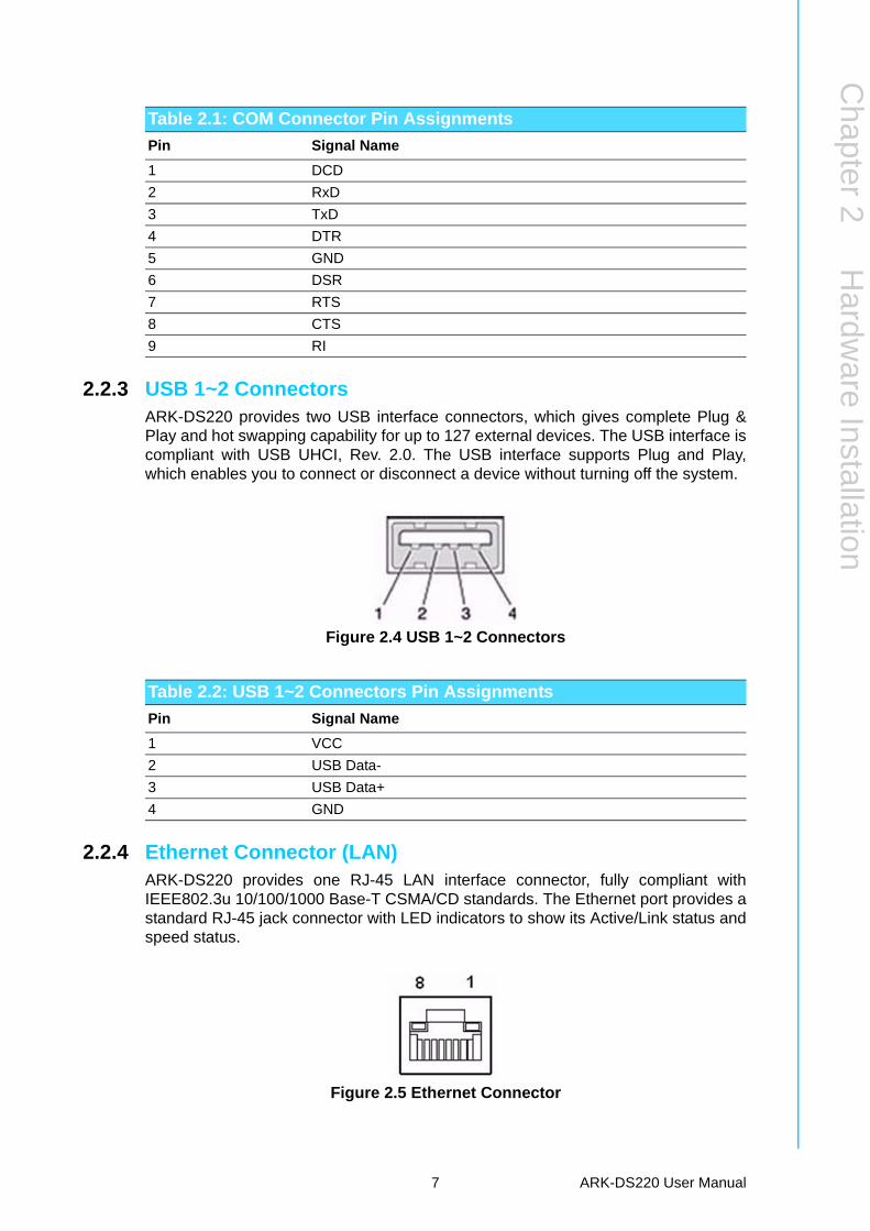
2.2.3 USB 1~2 ConnectorsARK-DS220 provides two USB interface connectors, which gives complete Plug &Play and hot swapping capability for up to 127 external devices. The USB interface iscompliant with USB UHCI, Rev. 2.0. The USB interface supports Plug and Play,which enables you to connect or disconnect a device without turning off the system.
Figure 2.4 USB 1~2 Connectors
2.2.4 Ethernet Connector (LAN)ARK-DS220 provides one RJ-45 LAN interface connector, fully compliant withIEEE802.3u 10/100/1000 Base-T CSMA/CD standards. The Ethernet port provides astandard RJ-45 jack connector with LED indicators to show its Active/Link status andspeed status.
Figure 2.5 Ethernet Connector
Table 2.1: COM Connector Pin Assignments
Pin Signal Name
1 DCD
2 RxD
3 TxD
4 DTR
5 GND
6 DSR
7 RTS
8 CTS
9 RI
Table 2.2: USB 1~2 Connectors Pin Assignments
Pin Signal Name
1 VCC
2 USB Data-
3 USB Data+
4 GND
7 ARK-DS220 User Manual
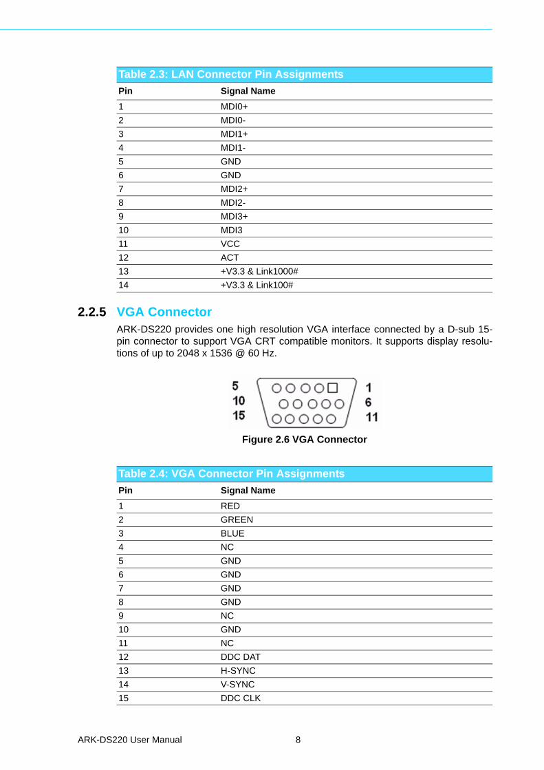
2.2.5 VGA ConnectorARK-DS220 provides one high resolution VGA interface connected by a D-sub 15-pin connector to support VGA CRT compatible monitors. It supports display resolu-tions of up to 2048 x 1536 @ 60 Hz.
Figure 2.6 VGA Connector
Table 2.3: LAN Connector Pin Assignments
Pin Signal Name
1 MDI0+
2 MDI0-
3 MDI1+
4 MDI1-
5 GND
6 GND
7 MDI2+
8 MDI2-
9 MDI3+
10 MDI3
11 VCC
12 ACT
13 +V3.3 & Link1000#
14 +V3.3 & Link100#
Table 2.4: VGA Connector Pin Assignments
Pin Signal Name
1 RED
2 GREEN
3 BLUE
4 NC
5 GND
6 GND
7 GND
8 GND
9 NC
10 GND
11 NC
12 DDC DAT
13 H-SYNC
14 V-SYNC
15 DDC CLK
ARK-DS220 User Manual 8

Chapter 2
Hardw
areInstallation
2.2.6 Audio ConnectorLine Out: Stereo speakers, earphone or front surround speakers can be connectedto the line out jack.
MIC In: Microphone must be connected to MIC In jack.
Figure 2.7 Line-out and MIC Connector
2.3 JAE TX-25 Plug ConnectorARK-DS220 provides one 80-pin right angle blindmate JAE TX-25 Plug connector,higher tolerance on mating misalignment, enables plug and unplug mechanismbetween ARK-DS220 and JAE TX-24 Receptacle connectors inside the displaypanel.
Figure 2.8 JAE TX-25 Plug Connector
Table 2.5: JAE TX-25 Plug Connector Pin Assignments
Pin Signal Name Pin Signal Name
1 DDP_3N 41 RSVD
2 DDP_3P 42 RSVD
3 GND 43 RSVD
4 DDP_2N 44 RSVD
5 DDP_2P 45 RSVD
6 GND 46 RSVD
7 DDP_1N 47 RSVD
8 DDP_1P 48 RSVD
9 GND 49 RSVD
10 DDP_0N 50 SYS_FAN
11 DDP_0P 51 UART_RXD
12 GND 52 UART_TXD
13 DDP_AUXN 53 GND
14 DDP_AUXP 54 StdA_SSRX-
15 DDP_HPD 55 StdA_SSRX+
9 ARK-DS220 User Manual
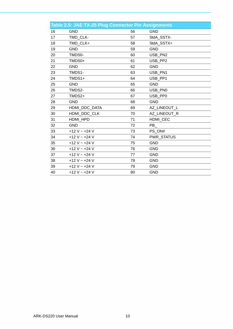
16 GND 56 GND
17 TMD_CLK- 57 StdA_SSTX-
18 TMD_CLK+ 58 StdA_SSTX+
19 GND 59 GND
20 TMDS0- 60 USB_PN2
21 TMDS0+ 61 USB_PP2
22 GND 62 GND
23 TMDS1- 63 USB_PN1
24 TMDS1+ 64 USB_PP1
25 GND 65 GND
26 TMDS2- 66 USB_PN0
27 TMDS2+ 67 USB_PP0
28 GND 68 GND
29 HDMI_DDC_DATA 69 AZ_LINEOUT_L
30 HDMI_DDC_CLK 70 AZ_LINEOUT_R
31 HDMI_HPD 71 HDMI_CEC
32 GND 72 PB_
33 +12 V ~ +24 V 73 PS_ON#
34 +12 V ~ +24 V 74 PWR_STATUS
35 +12 V ~ +24 V 75 GND
36 +12 V ~ +24 V 76 GND
37 +12 V ~ +24 V 77 GND
38 +12 V ~ +24 V 78 GND
39 +12 V ~ +24 V 79 GND
40 +12 V ~ +24 V 80 GND
Table 2.5: JAE TX-25 Plug Connector Pin Assignments
ARK-DS220 User Manual 10
Chapter 2
Hardw
areInstallation
2.4 Hardware Installation
2.4.1 Memory Installation1. Remove the bottom cover by loosening 6 fixing screws.2. Insert the memory into the SODIMM socket.3. Place the thermal pad (Dimension: L-60 mm x W-20 mm x H-2 mm) onto the
memory. 4. Replace the bottom cover and secure with screws.
Figure 2.9 Memory Installation
Figure 2.10 Thermal Pad Placement
11 ARK-DS220 User Manual
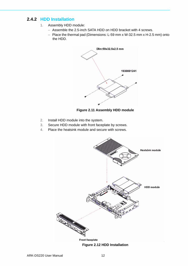
2.4.2 HDD Installation1. Assembly HDD module:
– Assemble the 2.5-inch SATA HDD on HDD bracket with 4 screws.– Place the thermal pad (Dimensions: L-59 mm x W-32.5 mm x H-2.5 mm) onto
the HDD.
Figure 2.11 Assembly HDD module
2. Install HDD module into the system.3. Secure HDD module with front faceplate by screws.4. Place the heatsink module and secure with screws.
Figure 2.12 HDD Installation
ARK-DS220 User Manual 12
Chapter 3
3 BIOS SettingsThis chapter introduces how to set BIOS configuration data.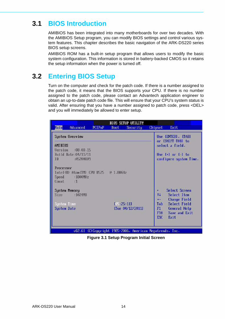
3.1 BIOS IntroductionAMIBIOS has been integrated into many motherboards for over two decades. Withthe AMIBIOS Setup program, you can modify BIOS settings and control various sys-tem features. This chapter describes the basic navigation of the ARK-DS220 seriesBIOS setup screens.
AMIBIOS ROM has a built-in setup program that allows users to modify the basicsystem configuration. This information is stored in battery-backed CMOS so it retainsthe setup information when the power is turned off.
3.2 Entering BIOS SetupTurn on the computer and check for the patch code. If there is a number assigned tothe patch code, it means that the BIOS supports your CPU. If there is no numberassigned to the patch code, please contact an Advantech application engineer toobtain an up-to-date patch code file. This will ensure that your CPU’s system status isvalid. After ensuring that you have a number assigned to patch code, press <DEL>and you will immediately be allowed to enter setup.
Figure 3.1 Setup Program Initial Screen
ARK-DS220 User Manual 14
Chapter 3
BIO
S S
ettings
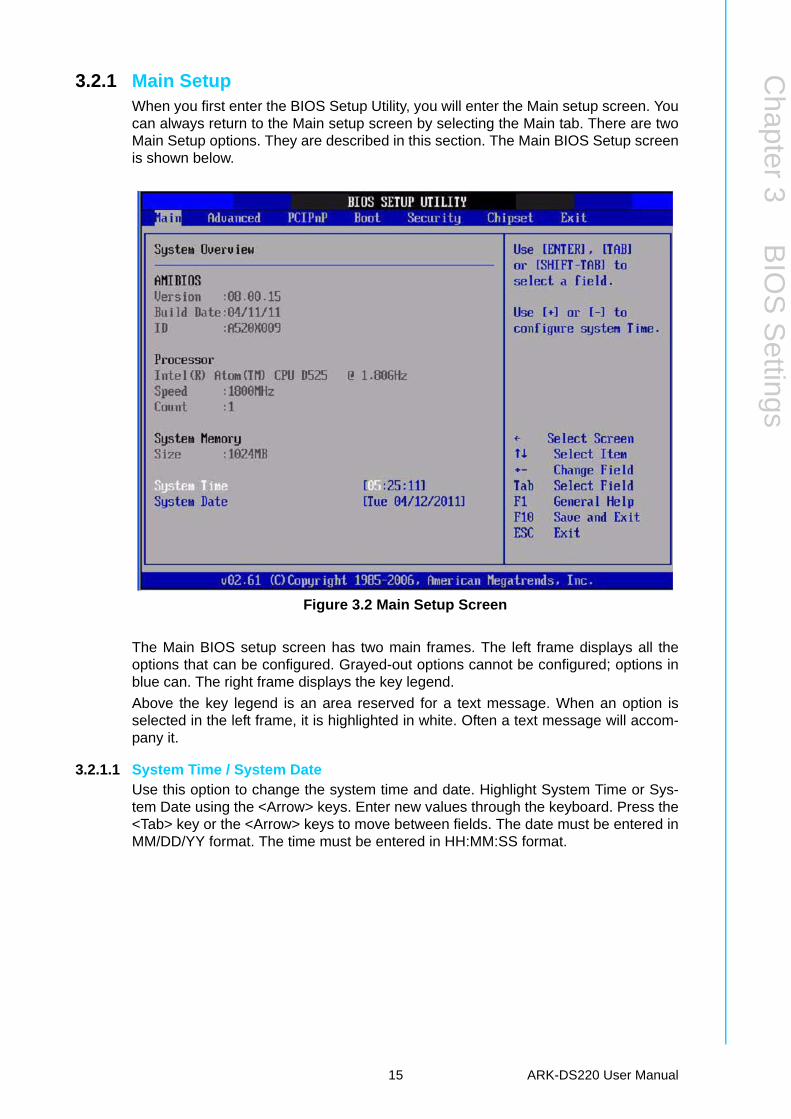
3.2.1 Main SetupWhen you first enter the BIOS Setup Utility, you will enter the Main setup screen. Youcan always return to the Main setup screen by selecting the Main tab. There are twoMain Setup options. They are described in this section. The Main BIOS Setup screenis shown below.
Figure 3.2 Main Setup Screen
The Main BIOS setup screen has two main frames. The left frame displays all theoptions that can be configured. Grayed-out options cannot be configured; options inblue can. The right frame displays the key legend.
Above the key legend is an area reserved for a text message. When an option isselected in the left frame, it is highlighted in white. Often a text message will accom-pany it.
3.2.1.1 System Time / System DateUse this option to change the system time and date. Highlight System Time or Sys-tem Date using the <Arrow> keys. Enter new values through the keyboard. Press the<Tab> key or the <Arrow> keys to move between fields. The date must be entered inMM/DD/YY format. The time must be entered in HH:MM:SS format.
15 ARK-DS220 User Manual
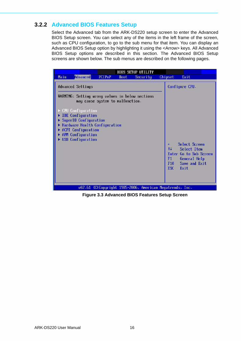
3.2.2 Advanced BIOS Features SetupSelect the Advanced tab from the ARK-DS220 setup screen to enter the AdvancedBIOS Setup screen. You can select any of the items in the left frame of the screen,such as CPU configuration, to go to the sub menu for that item. You can display anAdvanced BIOS Setup option by highlighting it using the <Arrow> keys. All AdvancedBIOS Setup options are described in this section. The Advanced BIOS Setupscreens are shown below. The sub menus are described on the following pages.
Figure 3.3 Advanced BIOS Features Setup Screen
ARK-DS220 User Manual 16
Chapter 3
BIO
S S
ettings
3.2.2.1 CPU Configuration
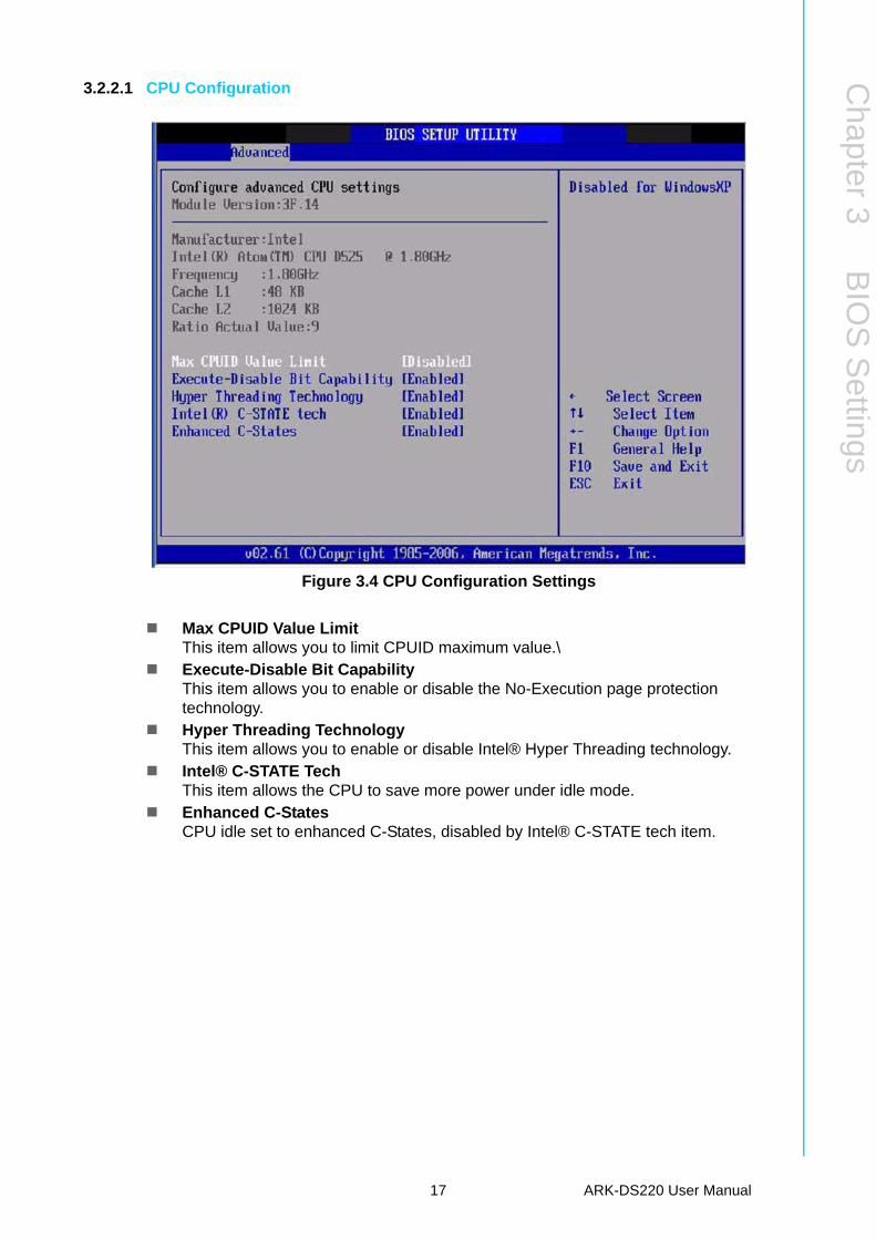
Figure 3.4 CPU Configuration Settings
Max CPUID Value LimitThis item allows you to limit CPUID maximum value.\
Execute-Disable Bit CapabilityThis item allows you to enable or disable the No-Execution page protection technology.
Hyper Threading TechnologyThis item allows you to enable or disable Intel® Hyper Threading technology.
Intel® C-STATE TechThis item allows the CPU to save more power under idle mode.
Enhanced C-StatesCPU idle set to enhanced C-States, disabled by Intel® C-STATE tech item.
17 ARK-DS220 User Manual
3.2.2.2 IDE Configuration
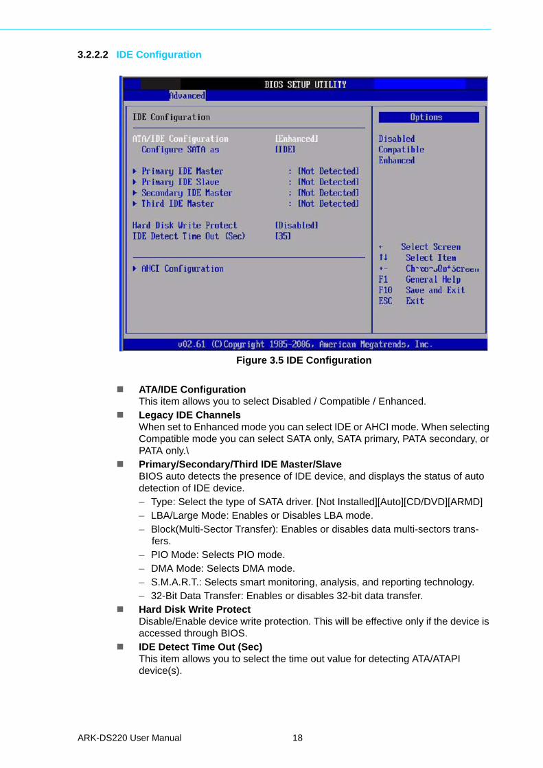
Figure 3.5 IDE Configuration
ATA/IDE ConfigurationThis item allows you to select Disabled / Compatible / Enhanced.
Legacy IDE ChannelsWhen set to Enhanced mode you can select IDE or AHCI mode. When selecting Compatible mode you can select SATA only, SATA primary, PATA secondary, or PATA only.\
Primary/Secondary/Third IDE Master/SlaveBIOS auto detects the presence of IDE device, and displays the status of auto detection of IDE device.– Type: Select the type of SATA driver. [Not Installed][Auto][CD/DVD][ARMD]– LBA/Large Mode: Enables or Disables LBA mode.– Block(Multi-Sector Transfer): Enables or disables data multi-sectors trans-
fers.– PIO Mode: Selects PIO mode.– DMA Mode: Selects DMA mode.– S.M.A.R.T.: Selects smart monitoring, analysis, and reporting technology.– 32-Bit Data Transfer: Enables or disables 32-bit data transfer.
Hard Disk Write ProtectDisable/Enable device write protection. This will be effective only if the device is accessed through BIOS.
IDE Detect Time Out (Sec)This item allows you to select the time out value for detecting ATA/ATAPI device(s).
ARK-DS220 User Manual 18
Chapter 3
BIO
S S
ettings
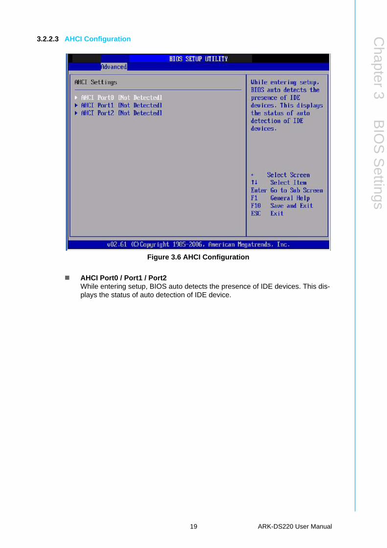
3.2.2.3 AHCI Configuration
Figure 3.6 AHCI Configuration
AHCI Port0 / Port1 / Port2While entering setup, BIOS auto detects the presence of IDE devices. This dis-plays the status of auto detection of IDE device.
19 ARK-DS220 User Manual
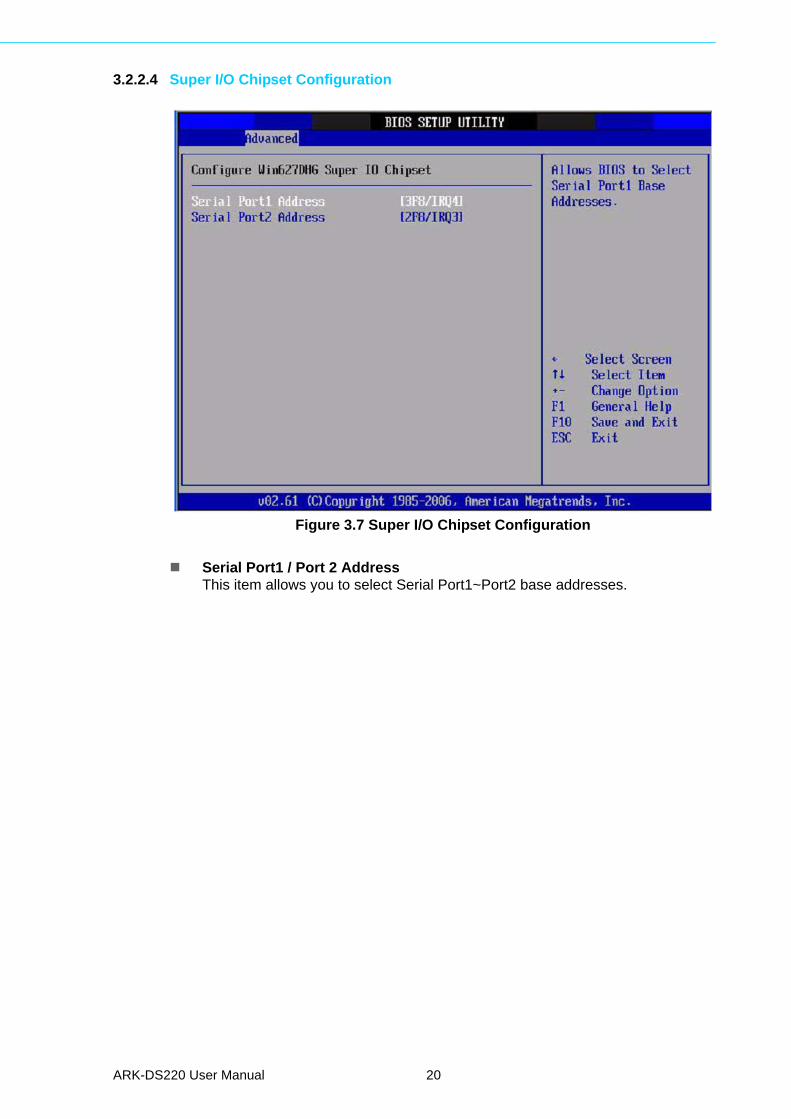
3.2.2.4 Super I/O Chipset Configuration
Figure 3.7 Super I/O Chipset Configuration
Serial Port1 / Port 2 AddressThis item allows you to select Serial Port1~Port2 base addresses.
ARK-DS220 User Manual 20
Chapter 3
BIO
S S
ettings
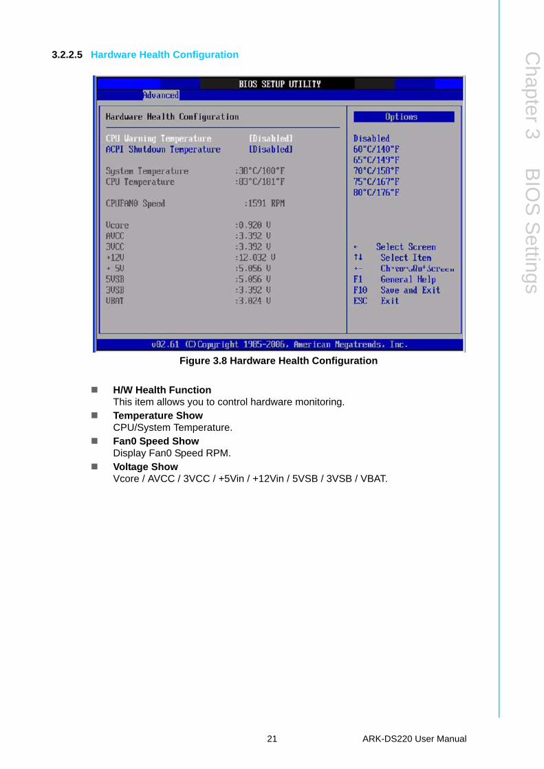
3.2.2.5 Hardware Health Configuration
Figure 3.8 Hardware Health Configuration
H/W Health FunctionThis item allows you to control hardware monitoring.
Temperature ShowCPU/System Temperature.
Fan0 Speed ShowDisplay Fan0 Speed RPM.
Voltage ShowVcore / AVCC / 3VCC / +5Vin / +12Vin / 5VSB / 3VSB / VBAT.
21 ARK-DS220 User Manual
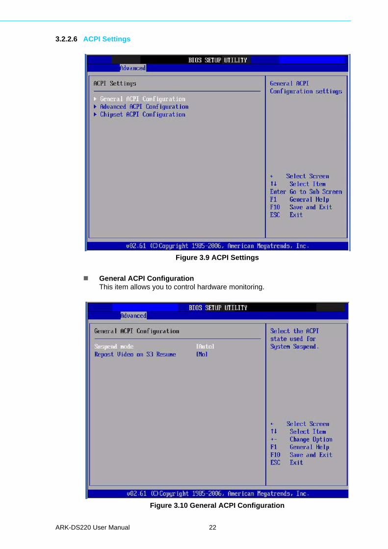
3.2.2.6 ACPI Settings
Figure 3.9 ACPI Settings
General ACPI ConfigurationThis item allows you to control hardware monitoring.
Figure 3.10 General ACPI Configuration
ARK-DS220 User Manual 22
Chapter 3
BIO
S S
ettings
– Suspend modeSelect the ACPI state used for system suspend.
– Report Video on S3 ResumeThis item allows you to invoke VA BIOS POST on S3/STR resume.
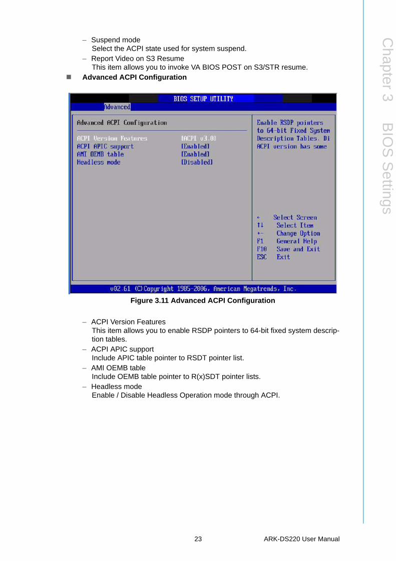
Advanced ACPI Configuration
Figure 3.11 Advanced ACPI Configuration
– ACPI Version FeaturesThis item allows you to enable RSDP pointers to 64-bit fixed system descrip-tion tables.
– ACPI APIC supportInclude APIC table pointer to RSDT pointer list.
– AMI OEMB tableInclude OEMB table pointer to R(x)SDT pointer lists.
– Headless modeEnable / Disable Headless Operation mode through ACPI.
23 ARK-DS220 User Manual
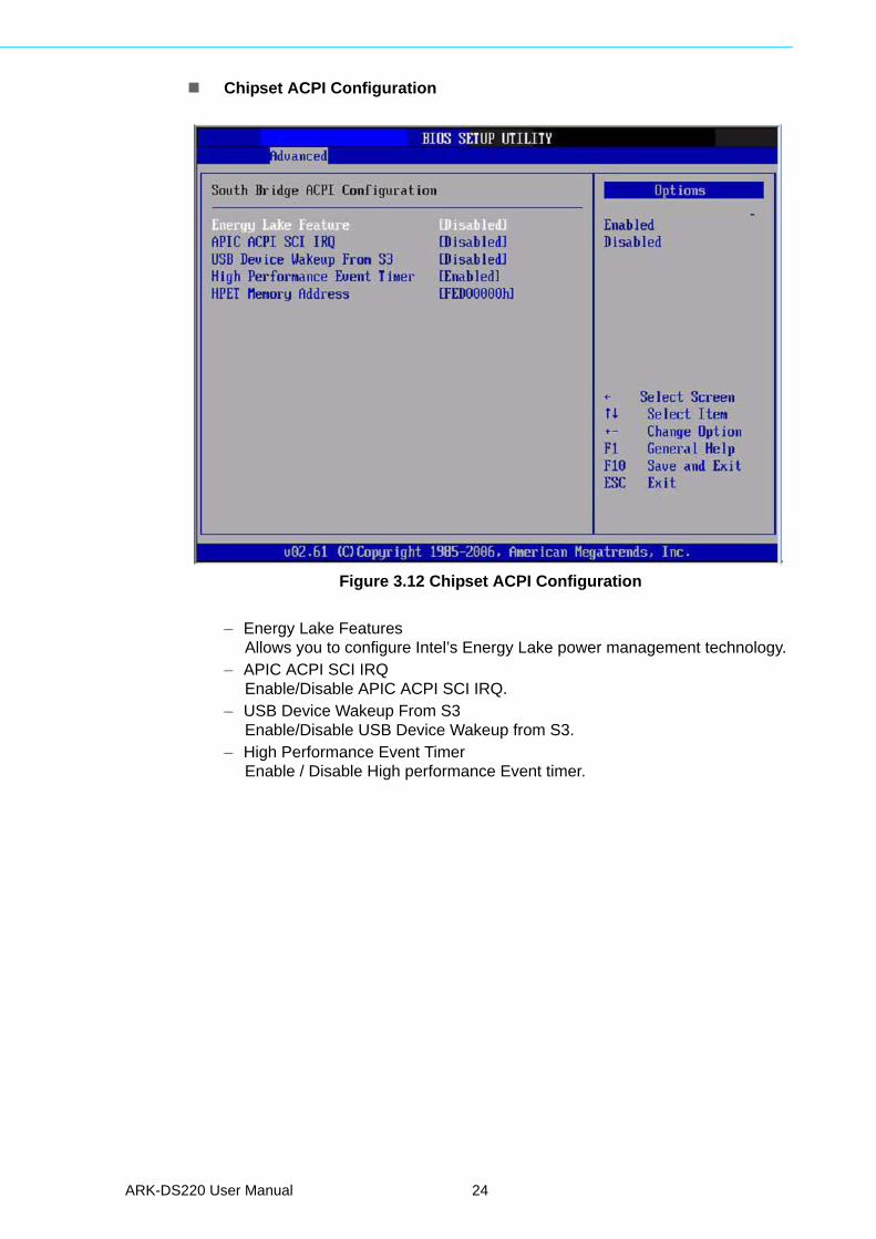
Chipset ACPI Configuration
Figure 3.12 Chipset ACPI Configuration
– Energy Lake FeaturesAllows you to configure Intel’s Energy Lake power management technology.
– APIC ACPI SCI IRQEnable/Disable APIC ACPI SCI IRQ.
– USB Device Wakeup From S3Enable/Disable USB Device Wakeup from S3.
– High Performance Event TimerEnable / Disable High performance Event timer.
ARK-DS220 User Manual 24
Chapter 3
BIO
S S
ettings
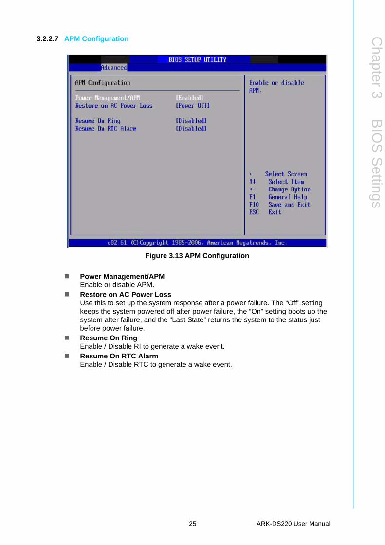
3.2.2.7 APM Configuration
Figure 3.13 APM Configuration
Power Management/APMEnable or disable APM.
Restore on AC Power LossUse this to set up the system response after a power failure. The “Off” setting keeps the system powered off after power failure, the “On” setting boots up the system after failure, and the “Last State” returns the system to the status just before power failure.
Resume On RingEnable / Disable RI to generate a wake event.
Resume On RTC AlarmEnable / Disable RTC to generate a wake event.
25 ARK-DS220 User Manual
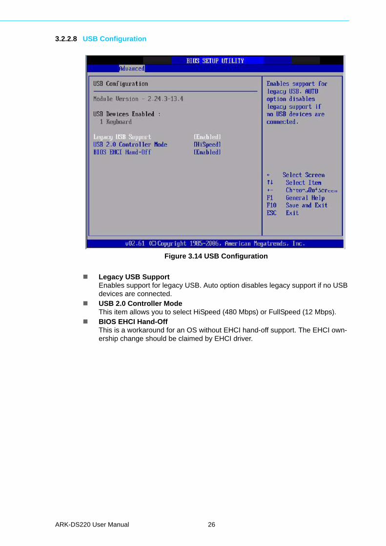
3.2.2.8 USB Configuration
Figure 3.14 USB Configuration
Legacy USB SupportEnables support for legacy USB. Auto option disables legacy support if no USB devices are connected.
USB 2.0 Controller ModeThis item allows you to select HiSpeed (480 Mbps) or FullSpeed (12 Mbps).
BIOS EHCI Hand-OffThis is a workaround for an OS without EHCI hand-off support. The EHCI own-ership change should be claimed by EHCI driver.
ARK-DS220 User Manual 26

Chapter 3
BIO
S S
ettings
3.2.3 PCI/PnP ConfigurationsSelect the PCI/PnP tab from the ARK-DS220 setup screen to enter the Plug and PlayBIOS Setup screen. You can display a Plug and Play BIOS Setup option by highlight-ing it using the <Arrow> keys. All Plug and Play BIOS Setup options are described inthis section. The Plug and Play BIOS Setup screen is shown below.
Figure 3.15 PCI/PnP Setup (Top)
3.2.3.1 Clear NVRAMSet this value to force the BIOS to clear the Non-Volatile Random Access Memory(NVRAM). The Optimal and Fail-Safe default setting is “No”.
3.2.3.2 Plug & Play O/SWhen set to “No”, BIOS configures all the devices in the system. When set to “Yes”and if you install a Plug and Play operating system, the operating system configuresPlug and Play devices not required for boot up.
3.2.3.3 PCI Latency TimerValue in units of PCI clocks for PCI device latency timer register.
3.2.3.4 Allocate IRQ to PCI VGAWhen set to “Yes”, assigns IRQ to PCI VGA card if card requests IRQ. When set to“No”, will not assign IRQ to PCI VGA card even if card requests an IRQ.
3.2.3.5 Palette SnoopingThis item is designed to solve problems caused by some non-standard VGA cards.
3.2.3.6 PCI IDE BusMasterWhen set to “Enabled” BIOS uses PCI busmastering for reading/writing to IDE drives.
27 ARK-DS220 User Manual
3.2.3.7 OffBoard PCI/ISA IDE CardSome PCI IDE cards may require this to be set to the PCI slot number that is holdingthe card. Setting to “Auto” will work for most PCI IDE cards.
3.2.3.8 IRQ3 / 4 / 5 / 7 / 9 / 10 / 11This item allows you respectively assign an interruptive type for IRQ-3,4,5,7,9,10,11.
3.2.3.9 DMA channel 0 / 1 / 3 / 5 / 6 / 7When set to “Available” will specify which DMA channel is available to be used byPCI/PnP devices. When set to “Reserved” will be reserved for use by legacy ISAdevices.
3.2.3.10 Reserved Memory SizeThis item allows you to reserve the size of memory block for legacy ISA device.
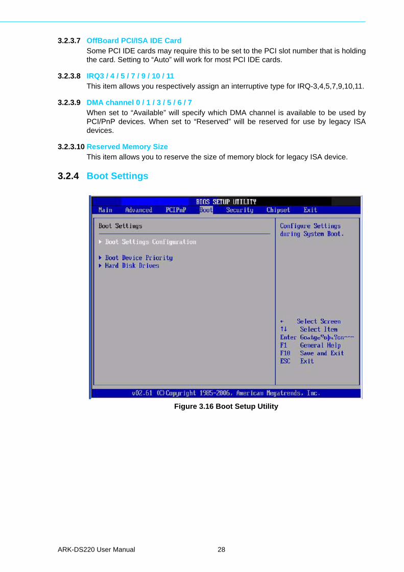
3.2.4 Boot Settings
Figure 3.16 Boot Setup Utility
ARK-DS220 User Manual 28
Chapter 3
BIO
S S
ettings
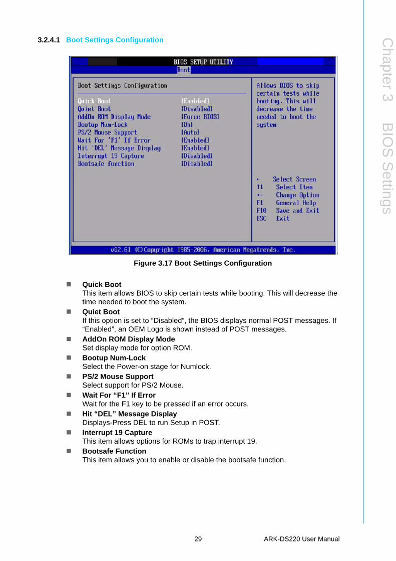
3.2.4.1 Boot Settings Configuration
Figure 3.17 Boot Settings Configuration
Quick BootThis item allows BIOS to skip certain tests while booting. This will decrease the time needed to boot the system.
Quiet BootIf this option is set to “Disabled”, the BIOS displays normal POST messages. If “Enabled”, an OEM Logo is shown instead of POST messages.
AddOn ROM Display ModeSet display mode for option ROM.
Bootup Num-LockSelect the Power-on stage for Numlock.
PS/2 Mouse SupportSelect support for PS/2 Mouse.
Wait For “F1” If ErrorWait for the F1 key to be pressed if an error occurs.
Hit “DEL” Message DisplayDisplays-Press DEL to run Setup in POST.
Interrupt 19 CaptureThis item allows options for ROMs to trap interrupt 19.
Bootsafe FunctionThis item allows you to enable or disable the bootsafe function.
29 ARK-DS220 User Manual
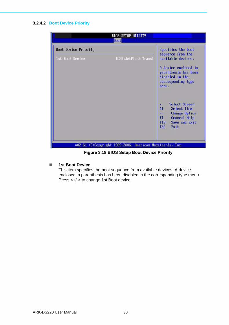
3.2.4.2 Boot Device Priority
Figure 3.18 BIOS Setup Boot Device Priority
1st Boot DeviceThis item specifies the boot sequence from available devices. A device enclosed in parenthesis has been disabled in the corresponding type menu. Press <+/-> to change 1st Boot device.
ARK-DS220 User Manual 30
Chapter 3
BIO
S S
ettings
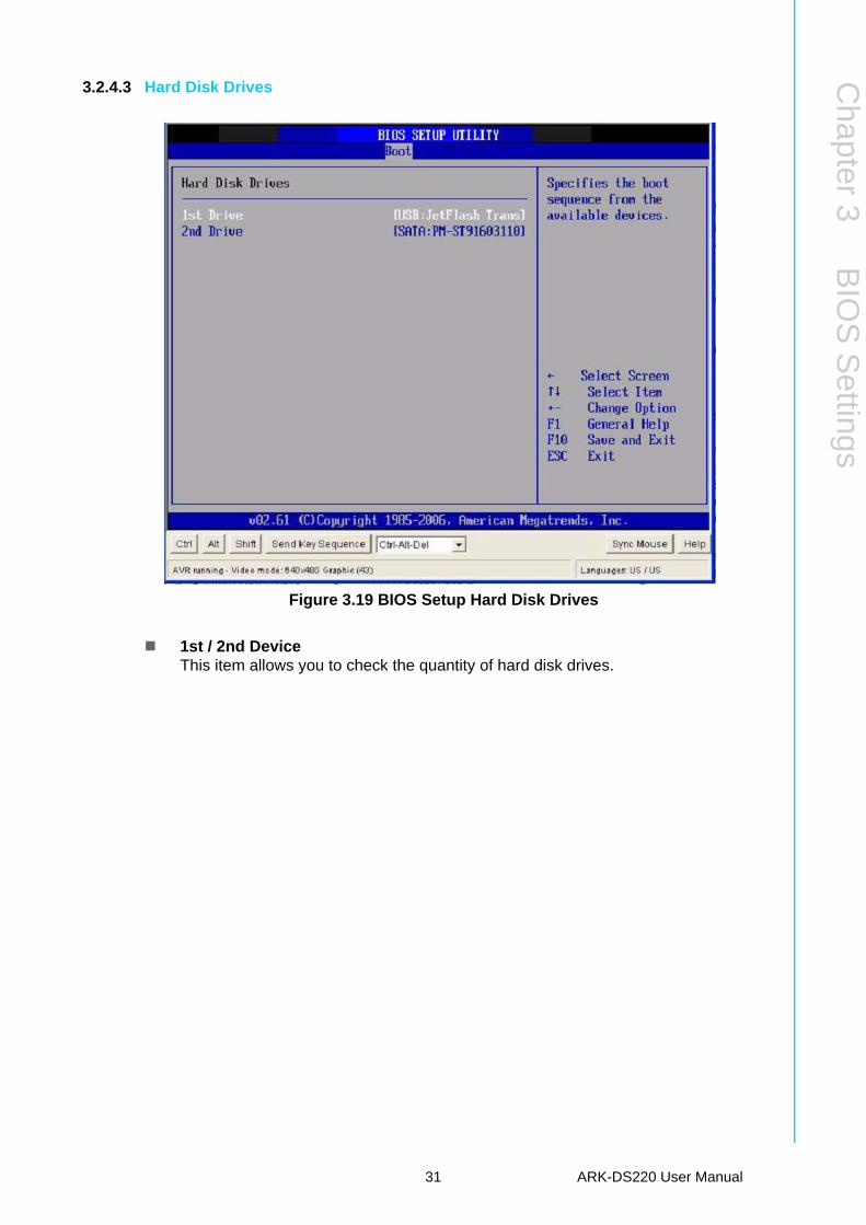
3.2.4.3 Hard Disk Drives
Figure 3.19 BIOS Setup Hard Disk Drives
1st / 2nd DeviceThis item allows you to check the quantity of hard disk drives.
31 ARK-DS220 User Manual
3.2.5 Security Setup
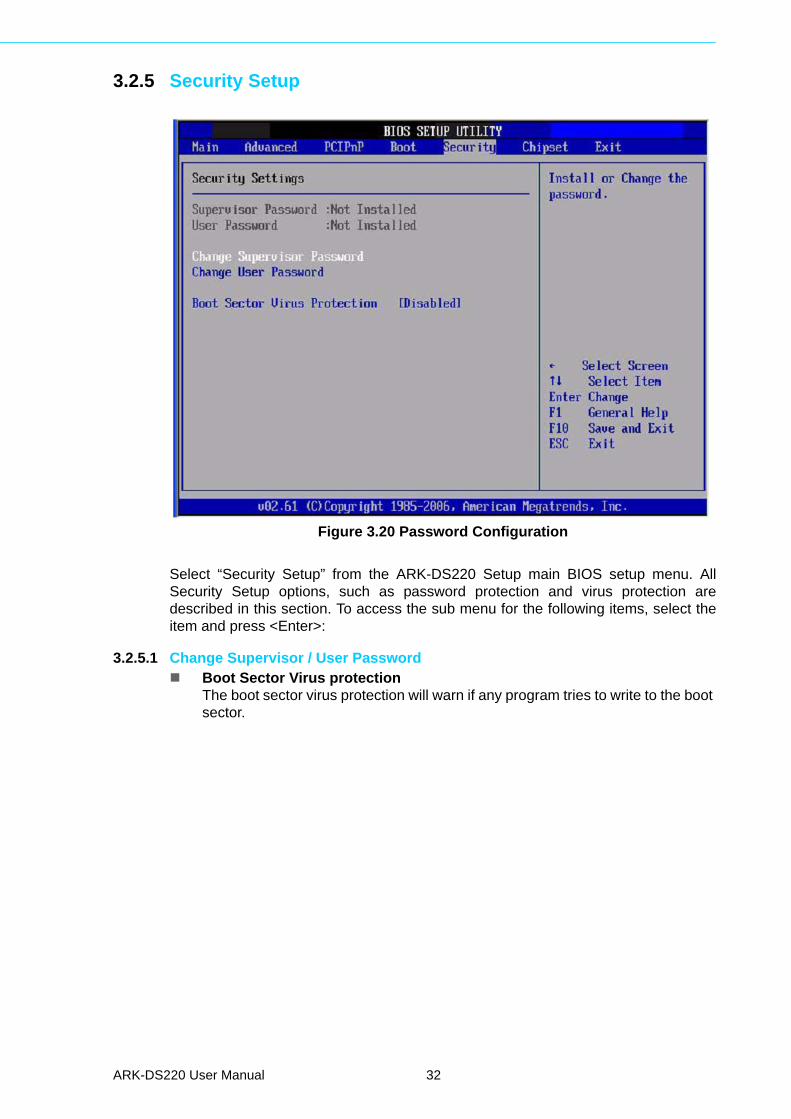
Figure 3.20 Password Configuration
Select “Security Setup” from the ARK-DS220 Setup main BIOS setup menu. AllSecurity Setup options, such as password protection and virus protection aredescribed in this section. To access the sub menu for the following items, select theitem and press <Enter>:
3.2.5.1 Change Supervisor / User Password Boot Sector Virus protection
The boot sector virus protection will warn if any program tries to write to the boot sector.
ARK-DS220 User Manual 32
Chapter 3
BIO
S S
ettings
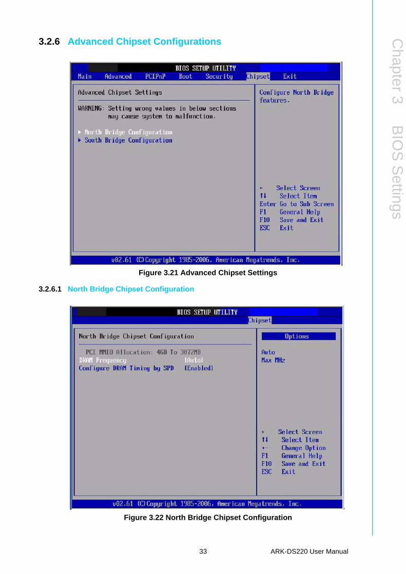
3.2.6 Advanced Chipset Configurations
Figure 3.21 Advanced Chipset Settings
3.2.6.1 North Bridge Chipset Configuration
Figure 3.22 North Bridge Chipset Configuration
33 ARK-DS220 User Manual
DRAM FrequencyThis item allows you to manually change DRAM frequency.
Configure DRAM Timing by SPDThis item allows you to enables or disable detection by DRAM SPD.
3.2.6.2 South Bridge Chipset Configuration
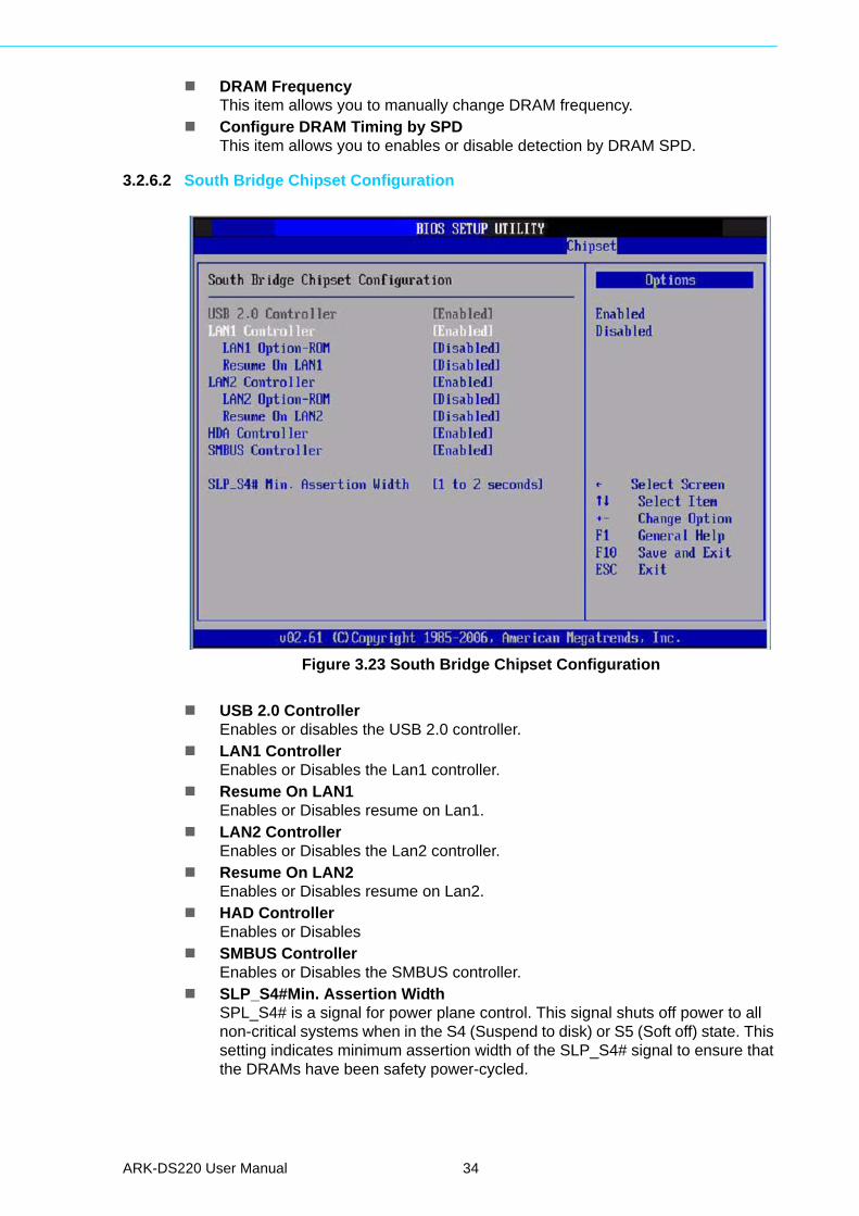
Figure 3.23 South Bridge Chipset Configuration
USB 2.0 ControllerEnables or disables the USB 2.0 controller.
LAN1 ControllerEnables or Disables the Lan1 controller.
Resume On LAN1Enables or Disables resume on Lan1.
LAN2 ControllerEnables or Disables the Lan2 controller.
Resume On LAN2Enables or Disables resume on Lan2.
HAD ControllerEnables or Disables
SMBUS ControllerEnables or Disables the SMBUS controller.
SLP_S4#Min. Assertion WidthSPL_S4# is a signal for power plane control. This signal shuts off power to all non-critical systems when in the S4 (Suspend to disk) or S5 (Soft off) state. This setting indicates minimum assertion width of the SLP_S4# signal to ensure that the DRAMs have been safety power-cycled.
ARK-DS220 User Manual 34
Chapter 3
BIO
S S
ettings
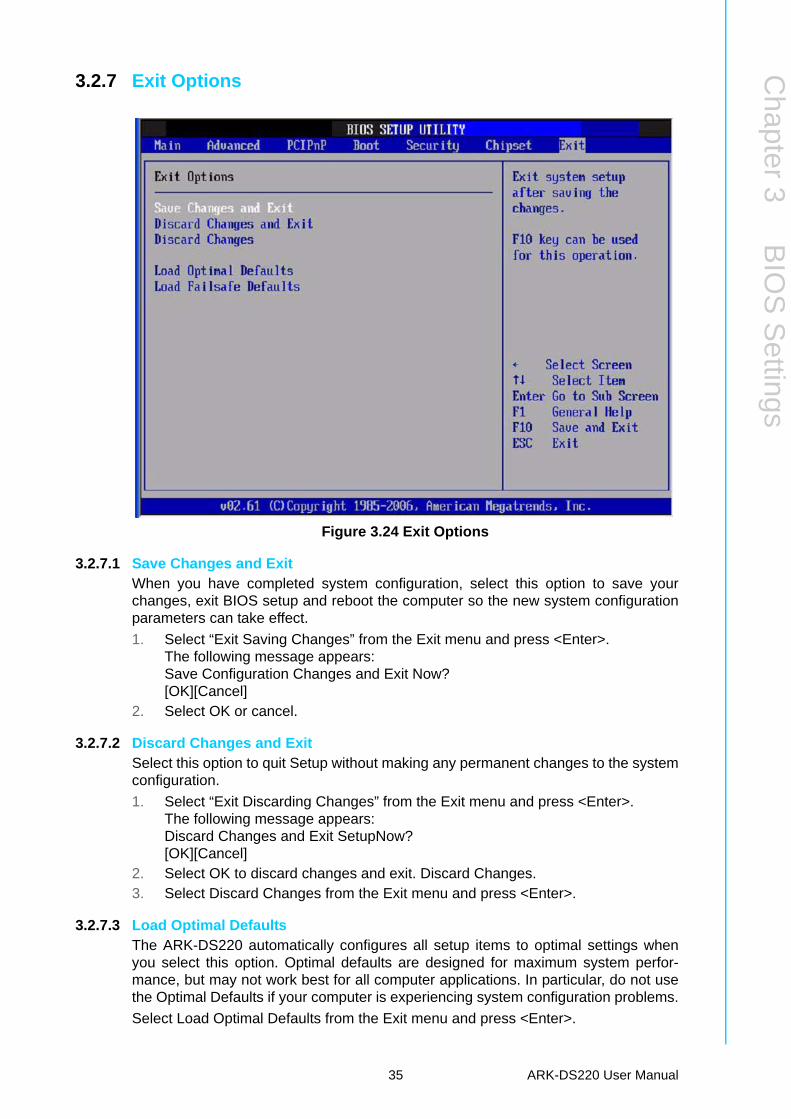
3.2.7 Exit Options
Figure 3.24 Exit Options
3.2.7.1 Save Changes and ExitWhen you have completed system configuration, select this option to save yourchanges, exit BIOS setup and reboot the computer so the new system configurationparameters can take effect.
1. Select “Exit Saving Changes” from the Exit menu and press <Enter>.The following message appears:Save Configuration Changes and Exit Now?[OK][Cancel]
2. Select OK or cancel.
3.2.7.2 Discard Changes and ExitSelect this option to quit Setup without making any permanent changes to the systemconfiguration.
1. Select “Exit Discarding Changes” from the Exit menu and press <Enter>.The following message appears:Discard Changes and Exit SetupNow?[OK][Cancel]
2. Select OK to discard changes and exit. Discard Changes.3. Select Discard Changes from the Exit menu and press <Enter>.
3.2.7.3 Load Optimal DefaultsThe ARK-DS220 automatically configures all setup items to optimal settings whenyou select this option. Optimal defaults are designed for maximum system perfor-mance, but may not work best for all computer applications. In particular, do not usethe Optimal Defaults if your computer is experiencing system configuration problems.
Select Load Optimal Defaults from the Exit menu and press <Enter>.
35 ARK-DS220 User Manual

3.2.7.4 Load Fail-Safe DefaultsThe ARK-DS220 automatically configures all setup options to fail-safe settings whenyou select this option. Fail-Safe Defaults are designed for maximum system stability,but not maximum performance. Select Fail-Safe Defaults if your computer is experi-encing system configuration problems.
1. Select “Load Fail-Safe Defaults” from the Exit menu and press <Enter>.The following message appears:Load Fail-Safe Defaults:[OK][Cancel]
2. Select OK to load Fail-Safe defaults.
ARK-DS220 User Manual 36
Chapter 4
4 Software InstallationThis chapter introduces driver installation.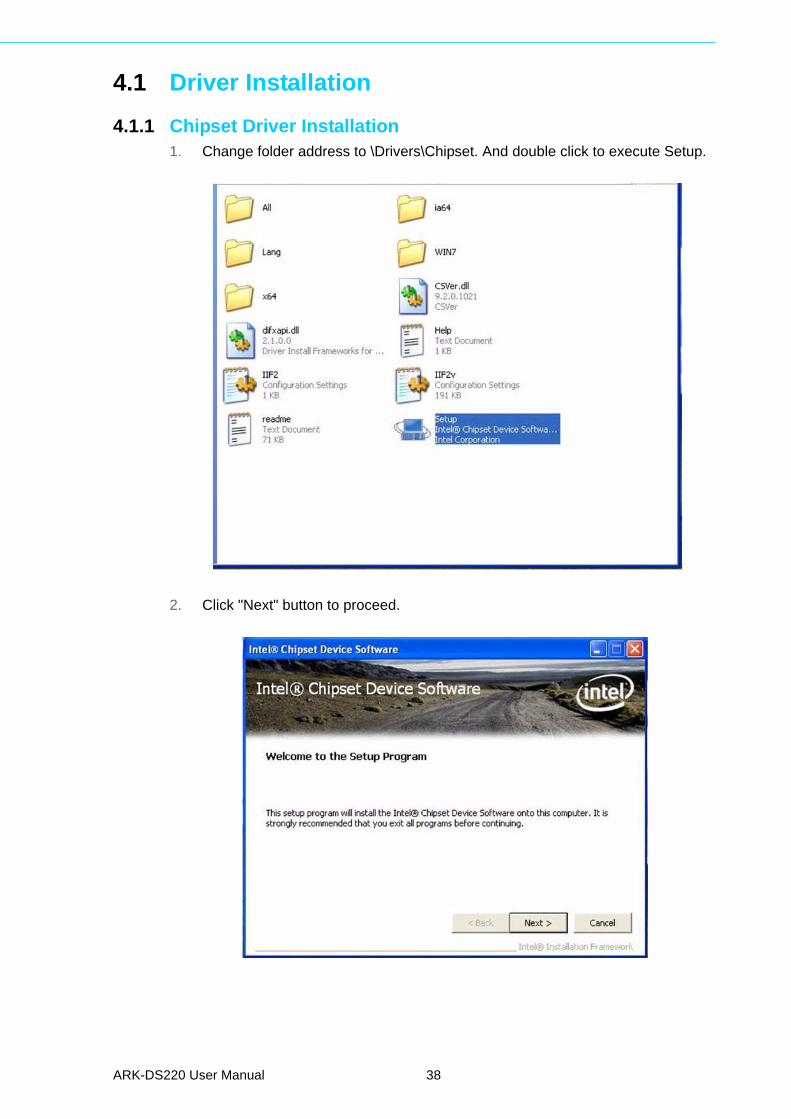
4.1 Driver Installation
4.1.1 Chipset Driver Installation1. Change folder address to \Drivers\Chipset. And double click to execute Setup.
2. Click "Next" button to proceed.
ARK-DS220 User Manual 38
Chapter 4
Softw
areInstallation
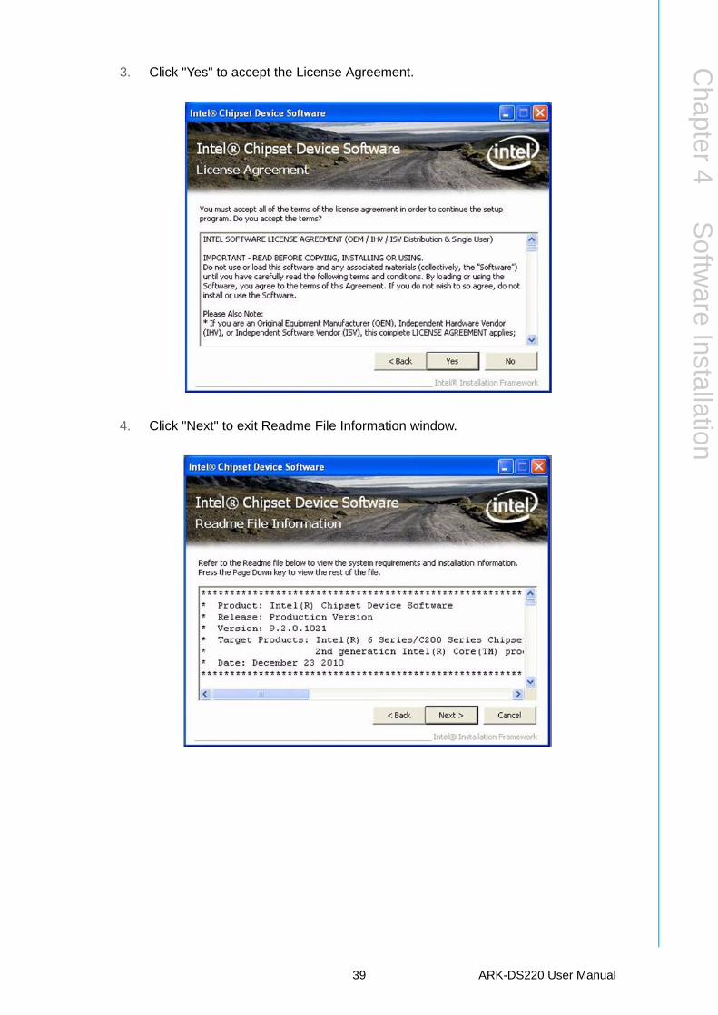
3. Click "Yes" to accept the License Agreement.
4. Click "Next" to exit Readme File Information window.
39 ARK-DS220 User Manual
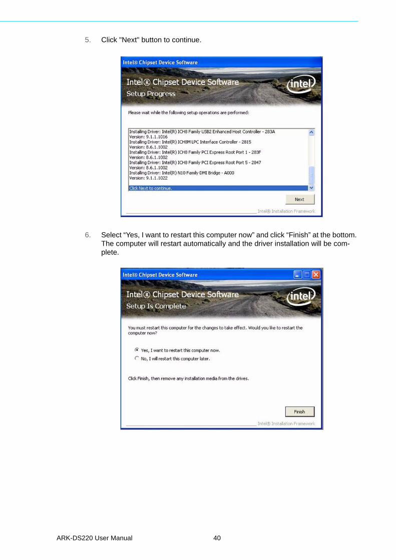
5. Click "Next" button to continue.
6. Select “Yes, I want to restart this computer now” and click “Finish” at the bottom. The computer will restart automatically and the driver installation will be com-plete.
ARK-DS220 User Manual 40
Chapter 4
Softw
areInstallation
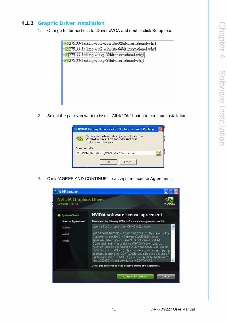
4.1.2 Graphic Driver Installation1. Change folder address to \Drivers\VGA and double click Setup.exe.
2. Select the path you want to install. Click “OK” button to continue installation.
3. Click "AGREE AND CONTINUE" to accept the License Agreement.
41 ARK-DS220 User Manual
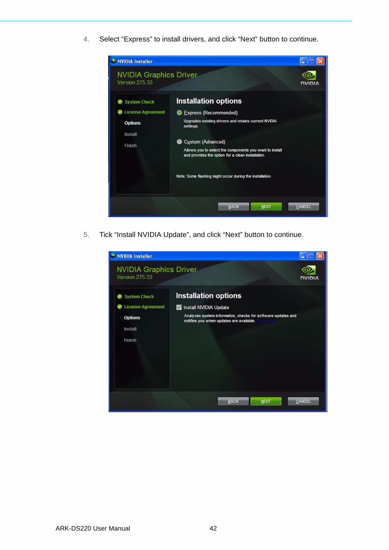
4. Select “Express” to install drivers, and click “Next” button to continue.
5. Tick “Install NVIDIA Update”, and click “Next” button to continue.
ARK-DS220 User Manual 42
Chapter 4
Softw
areInstallation
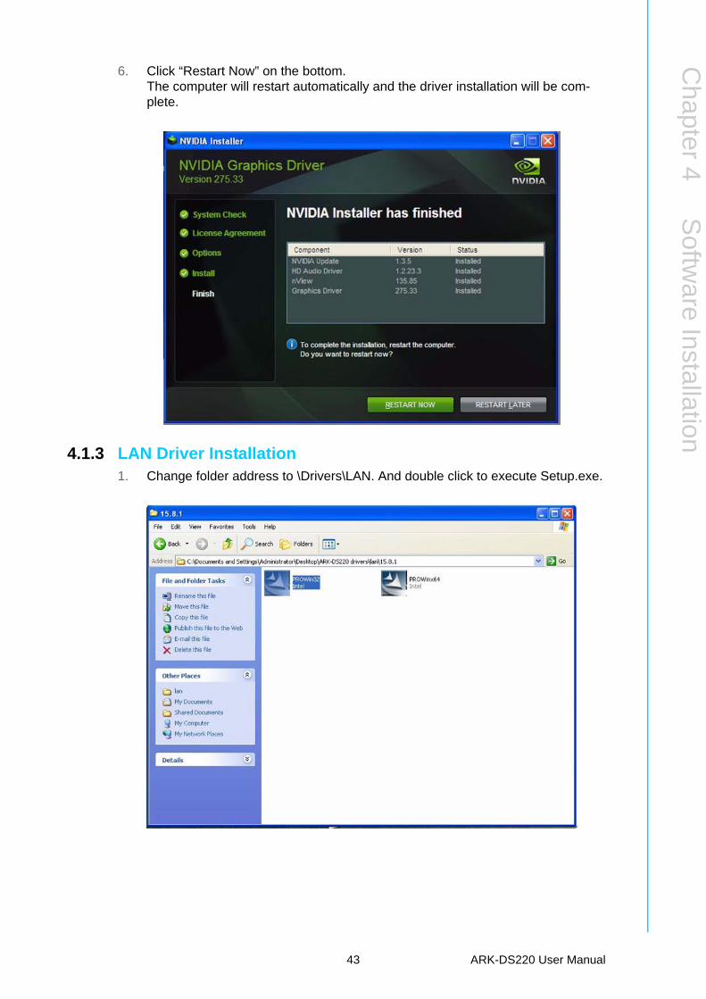
6. Click “Restart Now” on the bottom.The computer will restart automatically and the driver installation will be com-plete.
4.1.3 LAN Driver Installation1. Change folder address to \Drivers\LAN. And double click to execute Setup.exe.
43 ARK-DS220 User Manual
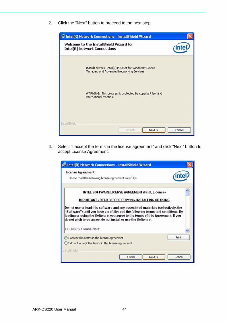
2. Click the "Next" button to proceed to the next step.
3. Select “I accept the terms in the license agreement” and click “Next” button to accept License Agreement.
ARK-DS220 User Manual 44
Chapter 4
Softw
areInstallation
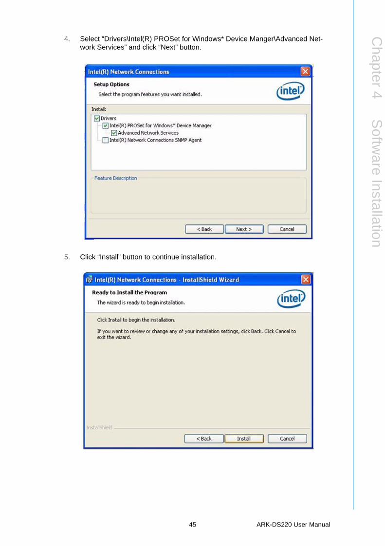
4. Select “Drivers\Intel(R) PROSet for Windows* Device Manger\Advanced Net-work Services” and click “Next” button.
5. Click “Install” button to continue installation.
45 ARK-DS220 User Manual
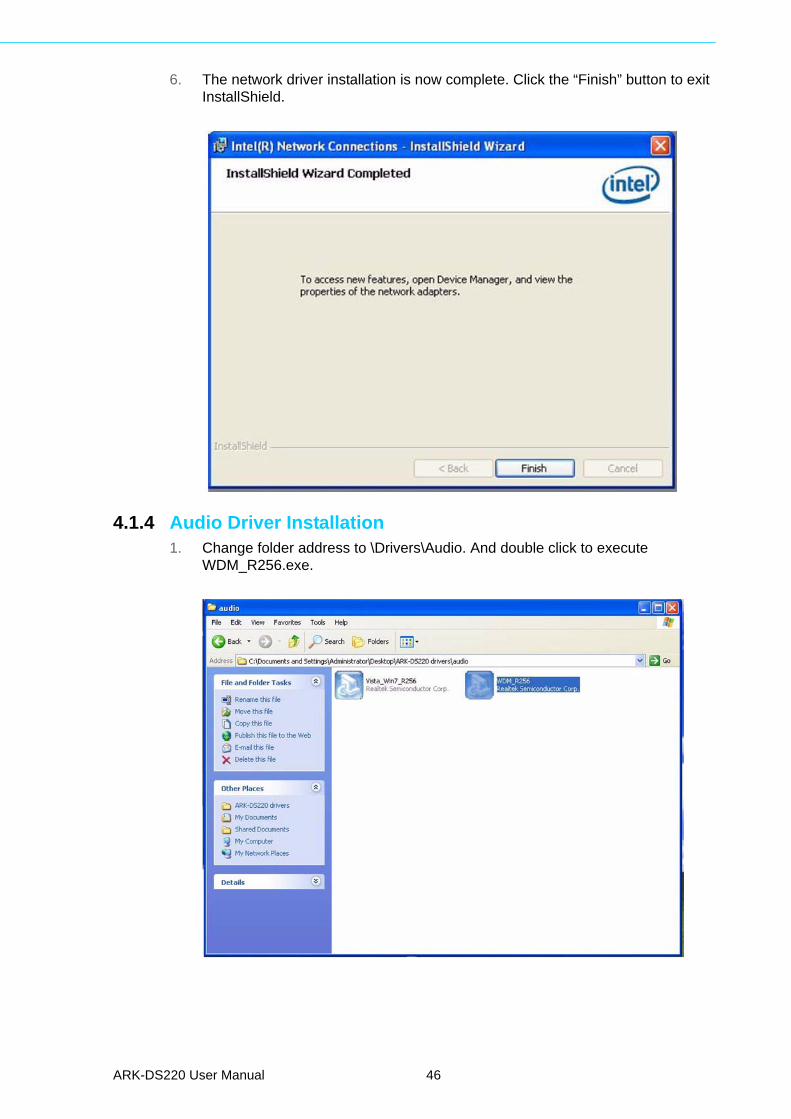
6. The network driver installation is now complete. Click the “Finish” button to exit InstallShield.
4.1.4 Audio Driver Installation1. Change folder address to \Drivers\Audio. And double click to execute
WDM_R256.exe.
ARK-DS220 User Manual 46
Chapter 4
Softw
areInstallation
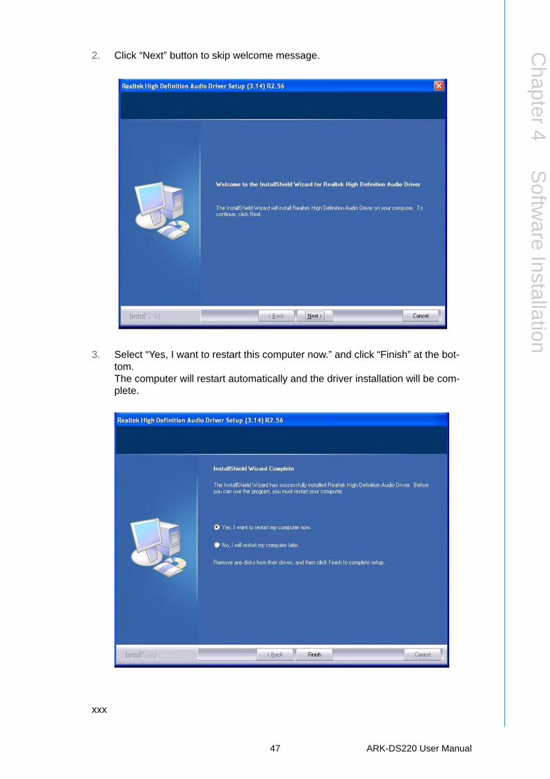
2. Click “Next” button to skip welcome message.
3. Select “Yes, I want to restart this computer now.” and click “Finish” at the bot-tom.The computer will restart automatically and the driver installation will be com-plete.
xxx
47 ARK-DS220 User Manual

www.advantech.comPlease verify specifications before quoting. This guide is intended for referencepurposes only.All product specifications are subject to change without notice.No part of this publication may be reproduced in any form or by any means,electronic, photocopying, recording or otherwise, without prior written permis-sion of the publisher.All brand and product names are trademarks or registered trademarks of theirrespective companies.© Advantech Co., Ltd. 2011