Embed Size (px)
Citation preview
Dugong DC Servo drive
User Manual and Installation Guide
Contents
1. Safety, policy and warranty. 1.1. Safety notes. 1.2. Policy. 1.3. Warranty.
2. Electric specifications. 2.1.Operation ranges.
3. Connections and pinouts. 3.1. Connectors. 3.1.1. Motor and Motor PSU connector. 3.1.2. Braking resistor connector. 3.1.3. Main connector. 3.1.4. Encoder interface. 3.1.5. USB interface.
4. Indicators and faults 4.1. LED indicators 4.2. Fault Conditions and Error Handling
5. Installation guide. 5.1. Installation of drive frame. 5.2. Motor wiring 5.3. Encoder Wiring 5.4. Shielding Techniques 5.5. Error Line Connection Examples
6. Power Supply – selection and filtering
7. Troubleshooting
1.1. Safety Notes Please read through this documentation before operating the device. The device can operate on low and medium DC bus Voltages up to 160VDC. Above 50VDC, the drive’s metal case must be connected to safety ground for safety purpose. Above 100VDC motor supply Voltage a braking resistor must be connected. Moving objects, like machine axis can be hazardous, avoid touching and keep distance from mechanic moving parts of the machine while the motor power supply is on and connected to the drives. The device should not be used where it can cause personal injury, death or high financial loss. Never open the drive’s chassis and never touch inner circuitry even if it’s unpowered. Take care of power supply’s correct polarity connection, wrong polarity connection of the Motor Power supply will cause permanent damage to the device. Never disconnect the motor from the drive when power supply is connected to the drive and is under Voltage. Do not short the motor output terminals, it may cause permanent damage to the device. The drives are in enclosure, but this metal case is not meant to protect the drive from dust and falling chips, liquid or other moisture material. Please take care to protect the drives from taint damage.
1.2. Policy CNCdrive cannot take responsibility for any personal injury and/or financial loss caused by their drives’ failure or caused by following an error in this documentation.
1.3. Warranty We give 12 months of standard warranty period with our Dugong drives. Customers may send back the drives within 15 days from purchase date if they are not satisfied with the performance. Using the drives outside of its specified electrical ranges may cause permanent damage to the device and void warranty. Opening the drive’s metal frame and making any modification in it voids warranty.
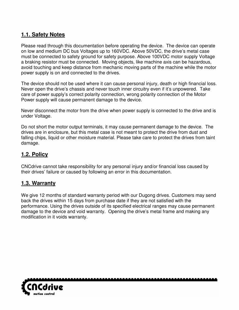
2. Electric specifications and limitations. 2.1.Operation ranges.
Property Min Typ Max Unit Notes
Motor supply voltage 12 - 160 VDC Optimal U=rated+10..20%
Motor current 0 - 35 A Limited by drive at set threshold, max. at 35A
Logic supply voltage 9 12 14 VDC
Logic supply current 100 200 250 mA
Operating temperature 10
65 °C Automatic shutdown at 65°C
Opto-isolator input Voltage 3 - - Use external series resistor in case of input Voltage>5VDC
Opto-isolator current 3 5 10 mA
Step input frequency 0
400 kHz
Direction signal stabile state minimum allowed valid time after step signal active edge
1 1 1 usec Step signal active and inactive edges can be configured in software by user.
Encoder maximum frequency 1 1 1 MHz With 4x coding
Error line output current 0.8 1 1.2 mA
Switching frequency 20 20 20 kHz
Maximum continuous motor current
35 35 35 Amper Current is limited at 35A
PID loop sampling time 1
65535 *60usec User setable in 60usec steps
Minimum allowed motor coil resistance
1 1 1 Ohm If resistance is lower it should be extended with inductor or with resistor/resistor wire.
Minimum allowed motor coil’s inductance
150 - - uH If inductance of the motor coil is lower, it should be extended with series coil.
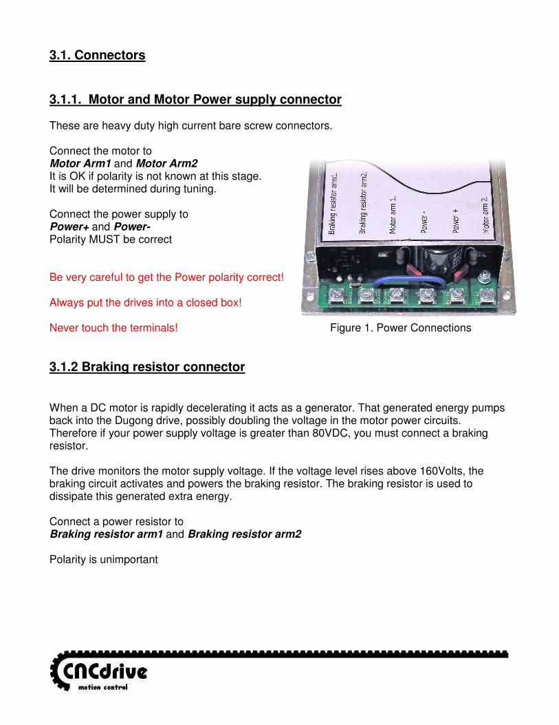
3.1. Connectors 3.1.1. Motor and Motor Power supply connector These are heavy duty high current bare screw connectors. Connect the motor to Motor Arm1 and Motor Arm2 It is OK if polarity is not known at this stage. It will be determined during tuning. Connect the power supply to Power+ and Power- Polarity MUST be correct Be very careful to get the Power polarity correct! Always put the drives into a closed box! Never touch the terminals! Figure 1. Power Connections
3.1.2 Braking resistor connector When a DC motor is rapidly decelerating it acts as a generator. That generated energy pumps back into the Dugong drive, possibly doubling the voltage in the motor power circuits. Therefore if your power supply voltage is greater than 80VDC, you must connect a braking resistor. The drive monitors the motor supply voltage. If the voltage level rises above 160Volts, the braking circuit activates and powers the braking resistor. The braking resistor is used to dissipate this generated extra energy. Connect a power resistor to Braking resistor arm1 and Braking resistor arm2 Polarity is unimportant
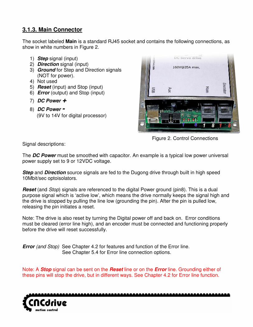
3.1.3. Main Connector The socket labeled Main is a standard RJ45 socket and contains the following connections, as show in white numbers in Figure 2.
1) Step signal (input) 2) Direction signal (input) 3) Ground for Step and Direction signals
(NOT for power). 4) Not used 5) Reset (input) and Stop (input) 6) Error (output) and Stop (input)
7) DC Power +
8) DC Power -
(9V to 14V for digital processor) Figure 2. Control Connections Signal descriptions: The DC Power must be smoothed with capacitor. An example is a typical low power universal power supply set to 9 or 12VDC voltage. Step and Direction source signals are fed to the Dugong drive through built in high speed 10Mbit/sec optoisolators. Reset (and Stop) signals are referenced to the digital Power ground (pin8). This is a dual purpose signal which is ‘active low’, which means the drive normally keeps the signal high and the drive is stopped by pulling the line low (grounding the pin). After the pin is pulled low, releasing the pin initiates a reset. Note: The drive is also reset by turning the Digital power off and back on. Error conditions must be cleared (error line high), and an encoder must be connected and functioning properly before the drive will reset successfully. Error (and Stop) See Chapter 4.2 for features and function of the Error line.
See Chapter 5.4 for Error line connection options. Note: A Stop signal can be sent on the Reset line or on the Error line. Grounding either of these pins will stop the drive, but in different ways. See Chapter 4.2 for Error line function.
3.1.4. Encoder Interface The plug labeled Encoder is a standard RJ45 jack and contains the following connections, as shown in red numbers in Figure 2.
1.) Ground 2.) 5V DC power for encoder 3.) Not used 4.) Not used 5.) A 6.) A_ 7.) B 8.) B_
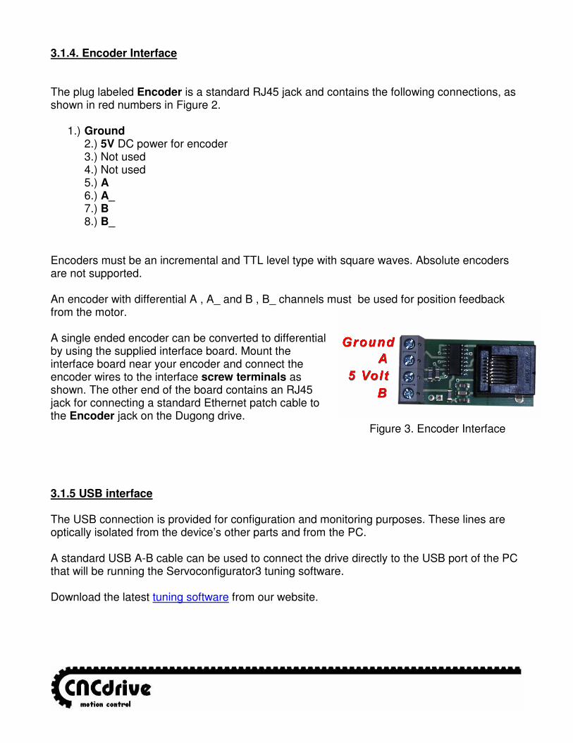
Encoders must be an incremental and TTL level type with square waves. Absolute encoders are not supported. An encoder with differential A , A_ and B , B_ channels must be used for position feedback from the motor. A single ended encoder can be converted to differential by using the supplied interface board. Mount the interface board near your encoder and connect the encoder wires to the interface screw terminals as shown. The other end of the board contains an RJ45 jack for connecting a standard Ethernet patch cable to the Encoder jack on the Dugong drive. Figure 3. Encoder Interface 3.1.5 USB interface The USB connection is provided for configuration and monitoring purposes. These lines are optically isolated from the device’s other parts and from the PC. A standard USB A-B cable can be used to connect the drive directly to the USB port of the PC that will be running the Servoconfigurator3 tuning software. Download the latest tuning software from our website.
4.1 LED indicators Indicator lights are visible on the edge of the board to give visual feedback on the drive operation. The positions are shown with blue numbers in Figure 2. Their functions are as follow: 1.) Power stage ready On when the power stage is ready and current is not under limitation. Off when current is under limitation (usually momentary, causing LED to ‘blink’) 2.) Controller running Flashing indicates normal operation of the controller. 3.) Limit override Off under normal conditions. On if the set servo limit reached, indicating the error condition. 4.) Digital power supply ON On when digital power supply voltage is present. 5.) Motor Clockwise On when power is applied to Arm1 connector. 6.) Motor Counterclockwise On when power is applied to Arm2 connector
4.2 Fault conditions and Error handling Error line is pin number 6 in the Main connector and is a dual purpose, bi directional line. This pin is ‘active low’, meaning that the line is normally high indicating no problems and normal operation. The drive will stop if this pin is pulled low (grounded) by one of these sources:
EXTERNAL activation; The line can be pulled low by an external source (CNC software, E-stop, etc). In this case, the drive will stop and remain stopped. When the pin is released, the drive will remain stopped, but can then be reset. CNC software should be set for ‘active low’ to use the Error line to stop the drive.
INTERNAL activation; The line is pulled low by the drive itself due to a fault
condition. Once stopped by an internal fault condition, the drive will remain stopped until the fault is cleared and the drive is reset. This line should be monitored by your CNC software to trigger an e-stop in the event of a fault. See Chapter 5.4 for details on Error line connection options.
Fault handling by the Dugong drive: Normal operation No faults, controller is running. Indication is Error line high and LED #2 is blinking with approximately 2Hz frequency. Overcurrent Fault The Dugong drive limits motor output current to the drive’s safe maximum of 35amps under normal operation. Certain events, such as a short circuit can cause the current to become uncontrollable. In this event, the drive will shut down when the current exceeds 40 amps Indication is Error line low and LED #2 flashing rapidly Encoder Fault The Dugong drive features encoder monitoring. If no encoder is connected or if a connected encoder becomes unreadable, the drive will issue an Encoder fault and shut off the motor power to prevent a dangerous ‘runaway’ situation. Indication is Error line low and LED #3 flashing. Note: the drive will not reset if a functioning encoder is not detected. Power Stage fault The Dugong will stop and to issue a Power Stage Fault for these events: 1) -Temperature Exceeded- drive’s aluminum backplate’s temperature reaches 65°C. 2) -Voltage Exceeded- more than 180V is applied to the motor power terminals. a) braking resistor is not connected and generated voltage exceeds 180V.
b) power supply greater than 180V is connected. Indication is Error line low and LED #1 switching off.
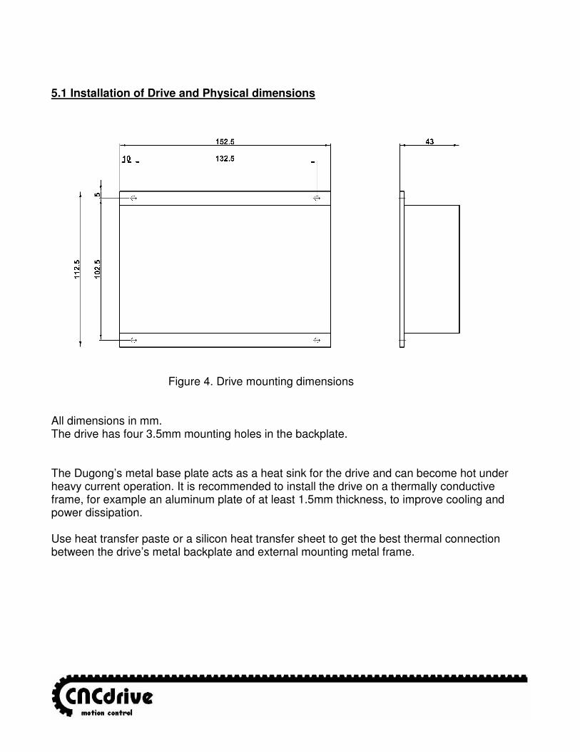
5.1 Installation of Drive and Physical dimensions
Figure 4. Drive mounting dimensions All dimensions in mm. The drive has four 3.5mm mounting holes in the backplate. The Dugong’s metal base plate acts as a heat sink for the drive and can become hot under heavy current operation. It is recommended to install the drive on a thermally conductive frame, for example an aluminum plate of at least 1.5mm thickness, to improve cooling and power dissipation. Use heat transfer paste or a silicon heat transfer sheet to get the best thermal connection between the drive’s metal backplate and external mounting metal frame.
5.2. Motor wiring. If possible use twisted pair of wires to connect motors to the drives to minimize radiated EMI from the wires. Use as high gauge wire as possible to minimize wire resistance. 5.3. Encoder wiring. To connect a differential encoder to the RJ45 style encoder plug on the Dugong drive, there are two options:
1) Cut one end off of a standard Ethernet patch cable, expose the individual wires and connect them to the appropriate terminals (or plug) on the encoder. Ethernet cables normally have clear plastic connectors allowing the wire colors can be readily seen, so you can figure out which color wires go to what pins on the cable plug.
2) If the encoder vendor supplied pre-made cable of sufficient length then simply connect those wires to an RJ45 plug. These plugs are readily available at electronics supply stores in both crimp and IDS types.
If using the supplied encoder interface board, a standard CAT5 grade Ethernet cable is all that is needed. A shielded cable is preferable. The cable length must be between 1 meter and 100 meters. Cables less than 1 meter in length may not meet the cable driver circuit’s impedance requirements. Use separate cables for motor power and for encoder signals and do not route them close to each other or in a common conduit. 5.4. Shielding techniques in general. The drive has ‘isolated’ motor power supply and digital power supply. This means the digital power supply ground and motor power supply’s ground are ‘floating’ to each other (not connected inside the drive) to avoid ground loops and therefore noise problems in communication. Do not use the same power supply for the motor power and the digital control power, for example a high voltage power supply that also has a low voltage output included which takes its primary power from the high voltage side. To protect your new drives and also for the most reliable communications between the computer and the CNC electronics, always use separated Power Supplies for the digital power and the motor power and do not connect the two GND points together, keep them separated and run the ground lines back to their respective power supplies. Use shielded cables for the Main connector and Encoder connector if possible. Connect the cable shields to an earth GROUND point at one end only, preferably at the Control box and not at the machine tool. If you connect both ends of a cable shield to ground, then current can flow thru the shield creating communication problems and also can carry high voltage back to your control box electronics in the event of a short circuit at the machine tool.
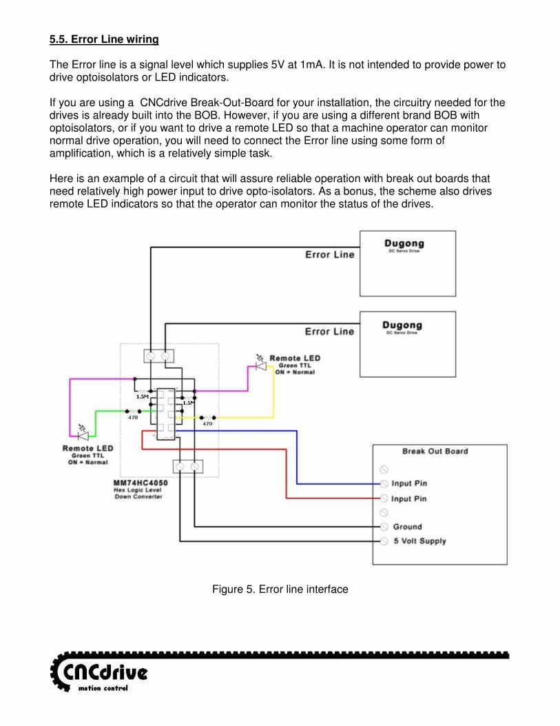
5.5. Error Line wiring The Error line is a signal level which supplies 5V at 1mA. It is not intended to provide power to drive optoisolators or LED indicators. If you are using a CNCdrive Break-Out-Board for your installation, the circuitry needed for the drives is already built into the BOB. However, if you are using a different brand BOB with optoisolators, or if you want to drive a remote LED so that a machine operator can monitor normal drive operation, you will need to connect the Error line using some form of amplification, which is a relatively simple task. Here is an example of a circuit that will assure reliable operation with break out boards that need relatively high power input to drive opto-isolators. As a bonus, the scheme also drives remote LED indicators so that the operator can monitor the status of the drives.
Figure 5. Error line interface
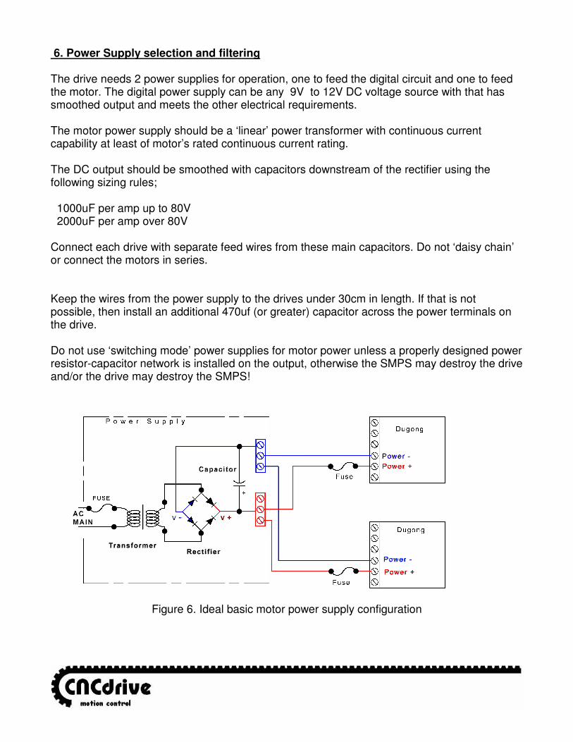
6. Power Supply selection and filtering The drive needs 2 power supplies for operation, one to feed the digital circuit and one to feed the motor. The digital power supply can be any 9V to 12V DC voltage source with that has smoothed output and meets the other electrical requirements. The motor power supply should be a ‘linear’ power transformer with continuous current capability at least of motor’s rated continuous current rating. The DC output should be smoothed with capacitors downstream of the rectifier using the following sizing rules; 1000uF per amp up to 80V 2000uF per amp over 80V Connect each drive with separate feed wires from these main capacitors. Do not ‘daisy chain’ or connect the motors in series. Keep the wires from the power supply to the drives under 30cm in length. If that is not possible, then install an additional 470uf (or greater) capacitor across the power terminals on the drive. Do not use ‘switching mode’ power supplies for motor power unless a properly designed power resistor-capacitor network is installed on the output, otherwise the SMPS may destroy the drive and/or the drive may destroy the SMPS!
Figure 6. Ideal basic motor power supply configuration
7. Troubleshooting
Q: When powering up the drive, the motor runs with full speed to one direction and stops after a while with error-limit reached LED on. A: Encoder is wired up in reverse, exchange motor Arm1 with Arm2 to reverse direction of the motor. Q: The motor is oscillating over the nullpoint when powerup. A: Tune the PID controller with the Servoconfigurator3 software. Q: I like to control my motor with a PLC which has 24V I/Os, is it possible? A: The step and direction pins are feed through optoisolators. Use a series resistor with the step and with the direction signal from the PLC. Resistor must be sized so that the opto-isolator current is limited under 10mA. Q: I like to control an AC servomotor with the drive, is it possible? A: No. The drive can only control brush type DC servomotors. Q: I have a disk-type servomotor with coil resistance of lower than 1 Ohms and an inductance of lower than 150uH, what to do? A:Use a resistor wire and/or inductor in series with the motor coil to extend resistance to at least 1 Ohm and inductance to at least 150uH otherwise the motor and/or drive may damage. Q: I have a motor that have a rated Voltage greater than 160VDC, can I used it with the drive. A: Yes, but do not connect a PSU with an overvoltage, absolute maximum motor Voltage ratings of the drive is 160VDC. If your motor has higher Voltage, it will operate from 160VDC, but with limited maximum torque. The best way is to use a higher Voltage rated drive in this case.
For more information visit: http://www.cncdrive.com e-mail: info@cncdrive
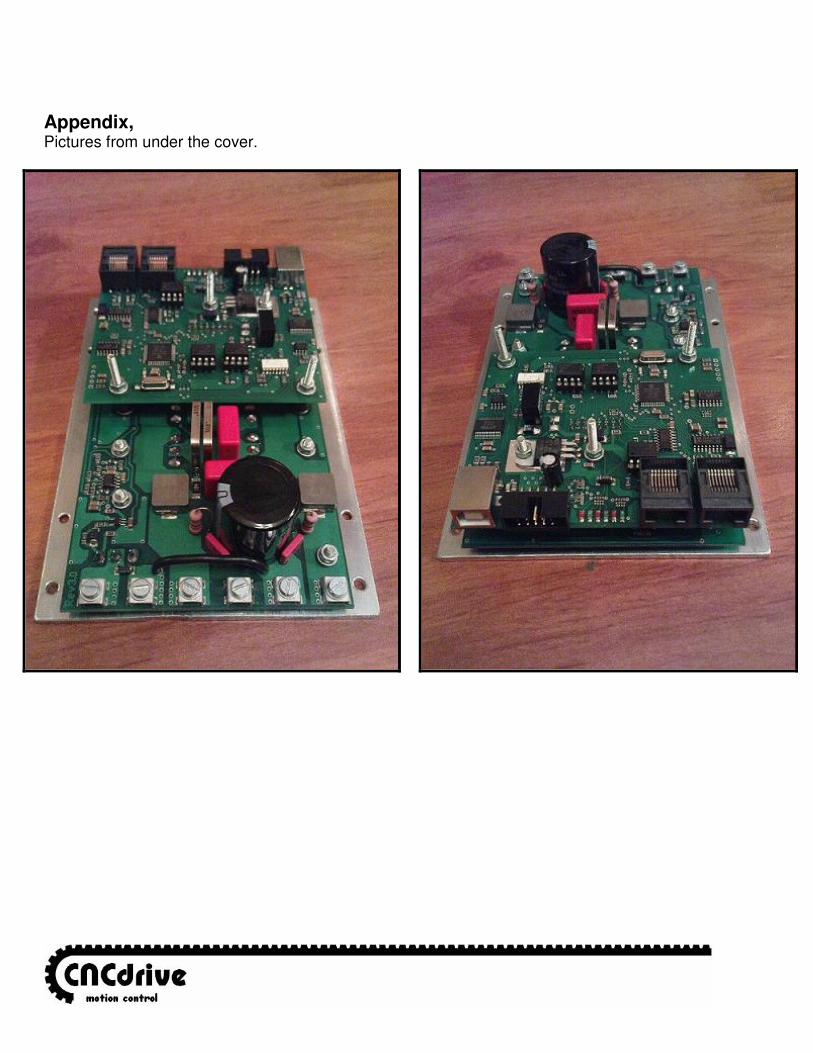
Appendix, Pictures from under the cover.


![Operating instructions Temperature transmitter · 2019. 10. 9. · Warning Alarm Failure 1 Drift warning threshold [drW] exceeded 2 Limit temperature internal electronics exceeded](https://img.pdfslide.us/doc/110x75/608590466c5b907c5c5fe51d/operating-instructions-temperature-transmitter-2019-10-9-warning-alarm-failure.jpg)