Embed Size (px)
Citation preview
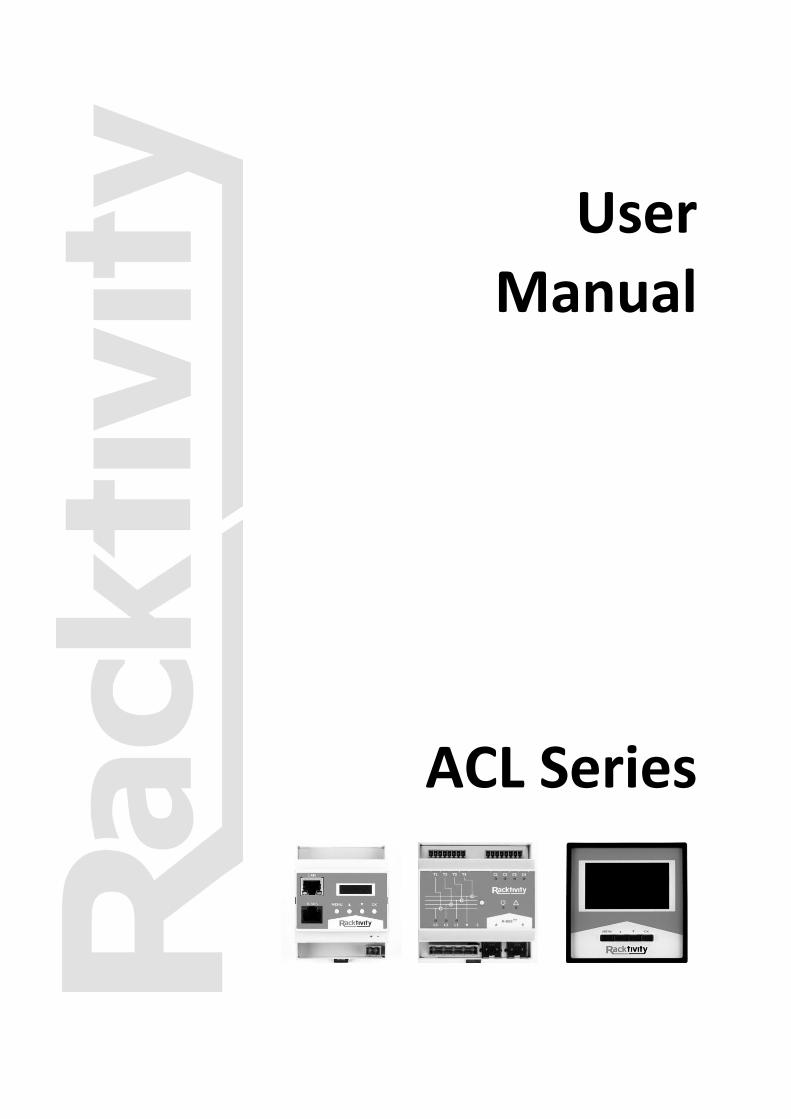
User
Manual
ACL Series
© 2011 Racktivity NV 2/38 Antwerpsesteenweg 19 - 9080 Lochristi - Belgium - www.racktivity.com v 2015.9.1
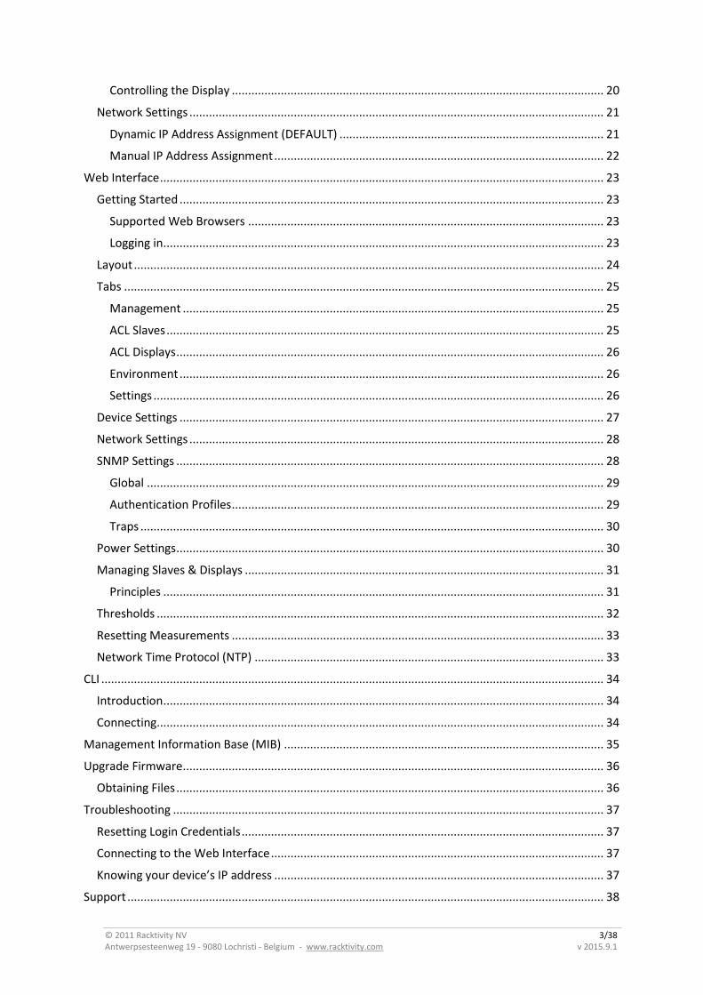
Contents Contents .................................................................................................................................................. 2
Introduction ............................................................................................................................................. 5
Features ............................................................................................................................................... 5
Applicable Models ............................................................................................................................... 6
Specifications ....................................................................................................................................... 6
Electrical Ratings ............................................................................................................................. 6
Operating Environment ................................................................................................................... 6
Dimensions ...................................................................................................................................... 6
User Account Overview ................................................................................................................... 7
Safety ................................................................................................................................................... 8
Certifications ................................................................................................................................... 9
Compliance ...................................................................................................................................... 9
Recycling ............................................................................................................................................ 10
Servicing & Repair ............................................................................................................................. 10
Additional Documentation ................................................................................................................ 10
Getting Started .................................................................................................................................. 11
Receiving Inspection ...................................................................................................................... 11
Inventory ....................................................................................................................................... 11
Installation ............................................................................................................................................. 12
Mounting the ACL Hardware ............................................................................................................. 12
ACL Master and Slave .................................................................................................................... 12
ACL Display .................................................................................................................................... 12
Connecting the ACL Hardware .......................................................................................................... 13
Installing Transducers ........................................................................................................................ 14
Specifications ................................................................................................................................. 14
Installation ..................................................................................................................................... 15
Installing Dry Contacts ....................................................................................................................... 16
Overview................................................................................................................................................ 17
ACL Master ........................................................................................................................................ 17
LEDs ............................................................................................................................................... 17
ACL Slave ........................................................................................................................................... 18
LEDs ............................................................................................................................................... 18
ACL Display ........................................................................................................................................ 19
Quick Configuration ............................................................................................................................... 20
Using the Onboard Display ................................................................................................................ 20
Activating the Display .................................................................................................................... 20
© 2011 Racktivity NV 3/38 Antwerpsesteenweg 19 - 9080 Lochristi - Belgium - www.racktivity.com v 2015.9.1
Controlling the Display .................................................................................................................. 20
Network Settings ............................................................................................................................... 21
Dynamic IP Address Assignment (DEFAULT) ................................................................................. 21
Manual IP Address Assignment ..................................................................................................... 22
Web Interface ........................................................................................................................................ 23
Getting Started .................................................................................................................................. 23
Supported Web Browsers ............................................................................................................. 23
Logging in ....................................................................................................................................... 23
Layout ................................................................................................................................................ 24
Tabs ................................................................................................................................................... 25
Management ................................................................................................................................. 25
ACL Slaves ...................................................................................................................................... 25
ACL Displays ................................................................................................................................... 26
Environment .................................................................................................................................. 26
Settings .......................................................................................................................................... 26
Device Settings .................................................................................................................................. 27
Network Settings ............................................................................................................................... 28
SNMP Settings ................................................................................................................................... 28
Global ............................................................................................................................................ 29
Authentication Profiles .................................................................................................................. 29
Traps .............................................................................................................................................. 30
Power Settings ................................................................................................................................... 30
Managing Slaves & Displays .............................................................................................................. 31
Principles ....................................................................................................................................... 31
Thresholds ......................................................................................................................................... 32
Resetting Measurements .................................................................................................................. 33
Network Time Protocol (NTP) ........................................................................................................... 33
CLI .......................................................................................................................................................... 34
Introduction ....................................................................................................................................... 34
Connecting ......................................................................................................................................... 34
Management Information Base (MIB) .................................................................................................. 35
Upgrade Firmware ................................................................................................................................. 36
Obtaining Files ................................................................................................................................... 36
Troubleshooting .................................................................................................................................... 37
Resetting Login Credentials ............................................................................................................... 37
Connecting to the Web Interface ...................................................................................................... 37
Knowing your device’s IP address ..................................................................................................... 37
Support .................................................................................................................................................. 38

© 2011 Racktivity NV 4/38 Antwerpsesteenweg 19 - 9080 Lochristi - Belgium - www.racktivity.com v 2015.9.1
© 2011 Racktivity NV 5/38 Antwerpsesteenweg 19 - 9080 Lochristi - Belgium - www.racktivity.com v 2015.9.1
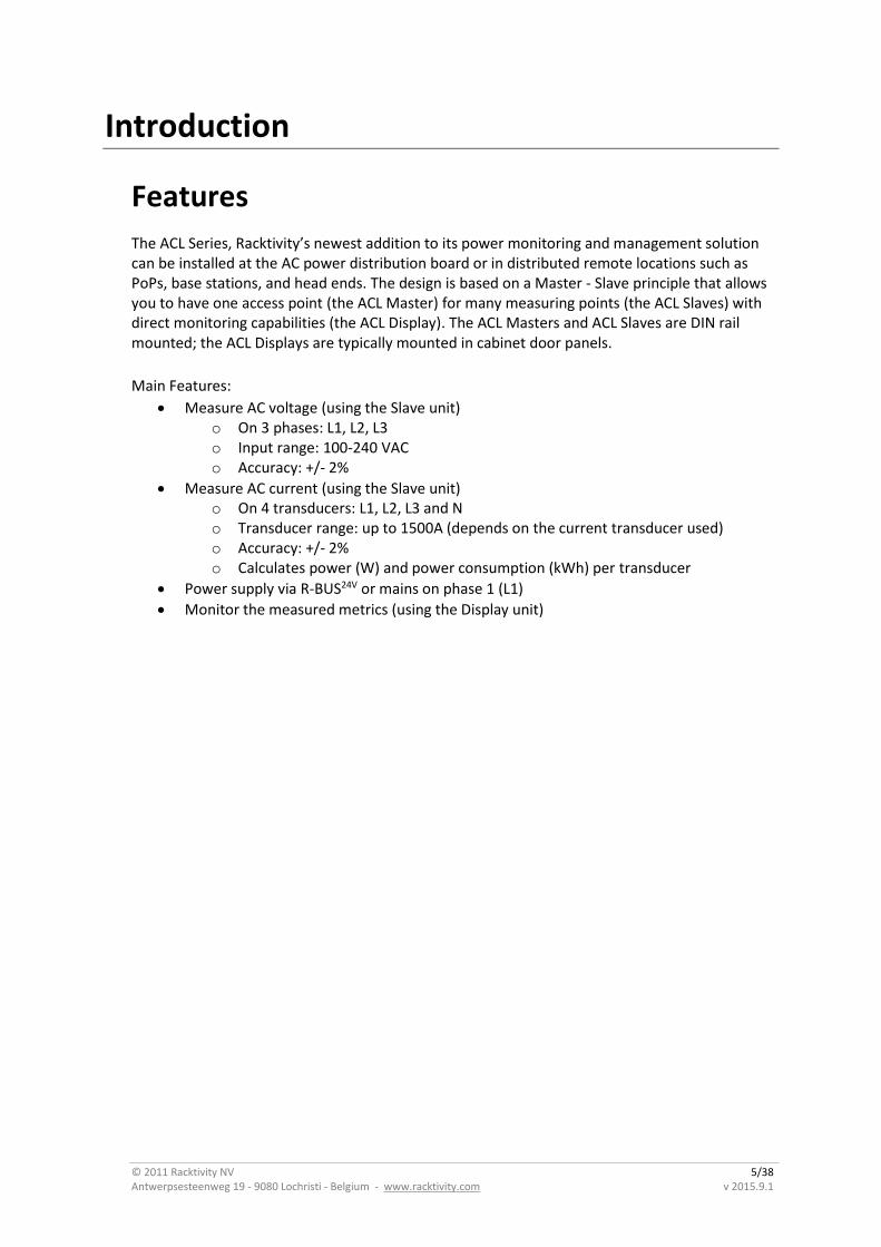
Introduction
Features
The ACL Series, Racktivity’s newest addition to its power monitoring and management solution can be installed at the AC power distribution board or in distributed remote locations such as PoPs, base stations, and head ends. The design is based on a Master - Slave principle that allows you to have one access point (the ACL Master) for many measuring points (the ACL Slaves) with direct monitoring capabilities (the ACL Display). The ACL Masters and ACL Slaves are DIN rail mounted; the ACL Displays are typically mounted in cabinet door panels.
Main Features:
Measure AC voltage (using the Slave unit) o On 3 phases: L1, L2, L3 o Input range: 100-240 VAC o Accuracy: +/- 2%
Measure AC current (using the Slave unit) o On 4 transducers: L1, L2, L3 and N o Transducer range: up to 1500A (depends on the current transducer used) o Accuracy: +/- 2% o Calculates power (W) and power consumption (kWh) per transducer
Power supply via R-BUS24V or mains on phase 1 (L1)
Monitor the measured metrics (using the Display unit)
© 2011 Racktivity NV 6/38 Antwerpsesteenweg 19 - 9080 Lochristi - Belgium - www.racktivity.com v 2015.9.1
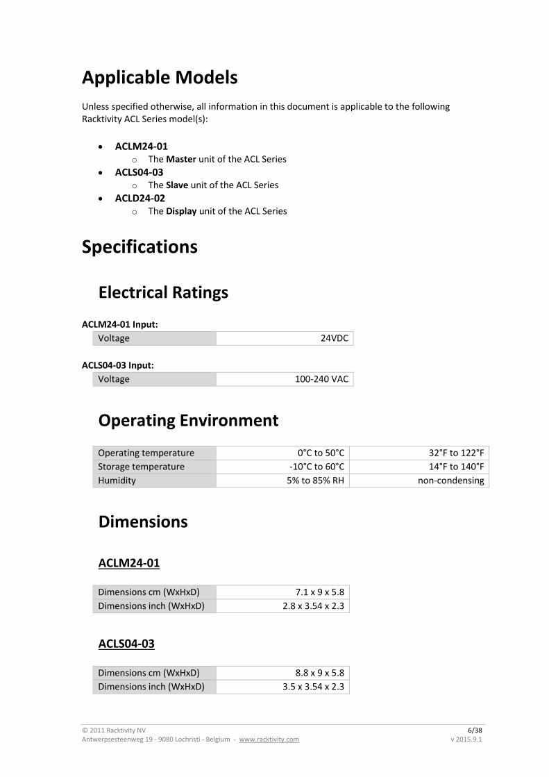
Applicable Models
Unless specified otherwise, all information in this document is applicable to the following Racktivity ACL Series model(s):
ACLM24-01 o The Master unit of the ACL Series
ACLS04-03 o The Slave unit of the ACL Series
ACLD24-02 o The Display unit of the ACL Series
Specifications
Electrical Ratings
ACLM24-01 Input:
Voltage 24VDC
ACLS04-03 Input:
Voltage 100-240 VAC
Operating Environment
Operating temperature 0°C to 50°C 32°F to 122°F
Storage temperature -10°C to 60°C 14°F to 140°F
Humidity 5% to 85% RH non-condensing
Dimensions
ACLM24-01
Dimensions cm (WxHxD) 7.1 x 9 x 5.8
Dimensions inch (WxHxD) 2.8 x 3.54 x 2.3
ACLS04-03
Dimensions cm (WxHxD) 8.8 x 9 x 5.8
Dimensions inch (WxHxD) 3.5 x 3.54 x 2.3
© 2011 Racktivity NV 7/38 Antwerpsesteenweg 19 - 9080 Lochristi - Belgium - www.racktivity.com v 2015.9.1
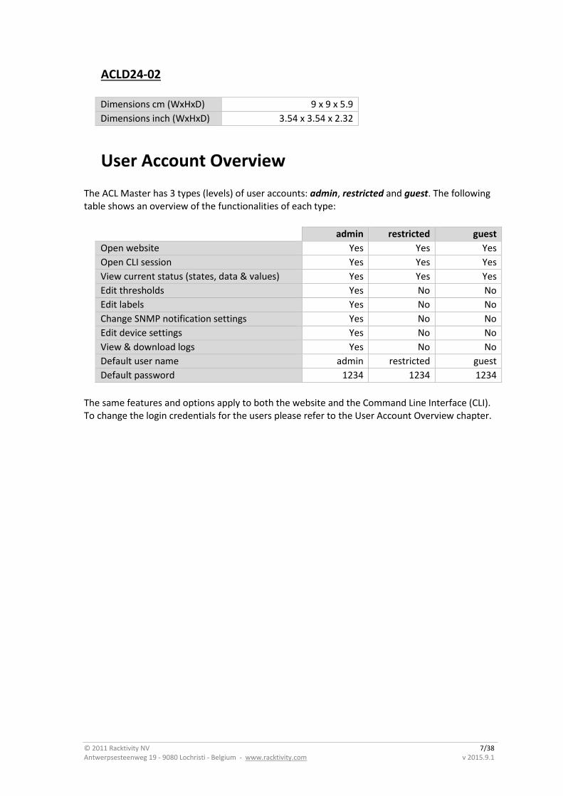
ACLD24-02
Dimensions cm (WxHxD) 9 x 9 x 5.9
Dimensions inch (WxHxD) 3.54 x 3.54 x 2.32
User Account Overview
The ACL Master has 3 types (levels) of user accounts: admin, restricted and guest. The following table shows an overview of the functionalities of each type:
admin restricted guest
Open website Yes Yes Yes
Open CLI session Yes Yes Yes
View current status (states, data & values) Yes Yes Yes
Edit thresholds Yes No No
Edit labels Yes No No
Change SNMP notification settings Yes No No
Edit device settings Yes No No
View & download logs Yes No No
Default user name admin restricted guest
Default password 1234 1234 1234
The same features and options apply to both the website and the Command Line Interface (CLI). To change the login credentials for the users please refer to the User Account Overview chapter.

© 2011 Racktivity NV 8/38 Antwerpsesteenweg 19 - 9080 Lochristi - Belgium - www.racktivity.com v 2015.9.1
Safety
Save these instructions!
This Safety Information contains important instructions that should be followed during installation and maintenance of the ACL Series equipment. It is intended for Racktivity customers who set up, install, relocate or maintain Racktivity equipment. Changes and modifications to this unit not specifically approved by Racktivity could void the warranty.
Electrical Hazard!
Read the following information before installing or operating your ACL Series equipment:
Do not work alone under hazardous conditions.
High current through conductive materials could cause severe burns.
Follow all local and national codes when installing the ACL Series equipment.
To avoid possible electrical shock and equipment damage, use only the supplied hardware.
Do not operate your ACL Series equipment with any covers removed or when damaged.
There are no user serviceable parts inside the ACL Series equipment. All repairs and service should be performed by authorized service personnel only.
The ACL Series equipment is designed for indoor use only in a controlled environment away from excess moisture, temperature extremes, conductive contaminants, dust, direct sunlight or magnetic sources.
Do not attempt to mount the ACL Series equipment to an insecure or unstable surface.
Never attempt to install electrical equipment during a thunderstorm.
Use of this equipment in life support applications or any medical applications is strictly prohibited since failure of this equipment can reasonably be expected to cause the failure of the life support equipment or to significantly affect its safety.
CAUTION: The ACL Master contains a lithium battery and should not be disposed of with general refuge. Dispose of the lithium battery in accordance with all local codes and regulations for products containing lithium batteries. Contact your local environmental control or disposal agency for further details. The battery is not intended to be user replaceable.

© 2011 Racktivity NV 9/38 Antwerpsesteenweg 19 - 9080 Lochristi - Belgium - www.racktivity.com v 2015.9.1
Certifications
Not all certifications are applicable to every model. Please check the label on your device.
CE / FCC
This device is designed in compliance with the requirements of the 4 following regulations:
EN 55022: Class B EN 61000-3-2 EN 61000-3-3 EN 55024
This device is certified to comply with Part 15 of the FCC rules.
Compliance
WEEE
Waste Electrical and Electronic Equipment
RoHS
Restriction of Hazardous Substances
© 2011 Racktivity NV 10/38 Antwerpsesteenweg 19 - 9080 Lochristi - Belgium - www.racktivity.com v 2015.9.1
Recycling
The materials used for shipping the ACL Series equipment are recyclable, please save them for later use or dispose of them appropriately.
Servicing & Repair
There are no user serviceable parts inside the ACL Series equipment. All repairs and service should be performed by authorized service personnel only.
Please refer to the Service Manual for RMA procedure.
Additional Documentation
Additional documentation and support regarding the following subjects is available on the Racktivity website www.racktivity.com/support.
API manual, overview & examples
Servicing (RMA) documentation
© 2011 Racktivity NV 11/38 Antwerpsesteenweg 19 - 9080 Lochristi - Belgium - www.racktivity.com v 2015.9.1
Getting Started
Receiving Inspection
Inspect the package (see Inventory chapter) and contents for shipping damage and make sure that all parts were received. Report any damage immediately to the shipping agent and report missing contents, damage, or other problems immediately to your reseller.
Inventory
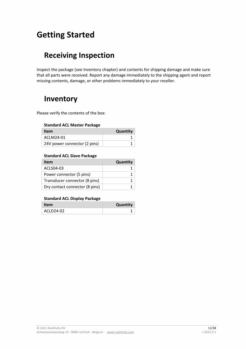
Please verify the contents of the box:
Standard ACL Master Package
Item Quantity
ACLM24-01 1
24V power connector (2 pins) 1
Standard ACL Slave Package
Item Quantity
ACLS04-03 1
Power connector (5 pins) 1
Transducer connector (8 pins) 1
Dry contact connector (8 pins) 1
Standard ACL Display Package
Item Quantity
ACLD24-02 1
© 2011 Racktivity NV 12/38 Antwerpsesteenweg 19 - 9080 Lochristi - Belgium - www.racktivity.com v 2015.9.1
Installation
Mounting the ACL Hardware
ACL Master and Slave
Mount the ACL Master and/or Slave to a horizontal DIN rail in your enclosure using the mounting slots at the back of the unit.
Hold the unit with the top (white) slider over the DIN rail and while slightly pulling the unit down.
Place the bottom (black) slider over the bottom of the DIN rail.
To remove the ACL Master and/or Slave use a flathead screwdriver to slightly pull the bottom (black) slider down. This will enable you to pull the bottom of the unit forward and release it from the DIN rail.
ACL Display
The ACL Display is typically mounted in cabinet door panels to provide an easy overview of the measured parameters.
The door panel cutout required should measure 9.0 x 9.0 cm (3.543 x 3.543 inch).
Mount the Display unit by sliding the device into the door panel cutout until it clicks into place.
To remove the ACL Display, gently press the device from the back through the door panel cutout until the snap mechanism holding it in place releases.
© 2011 Racktivity NV 13/38 Antwerpsesteenweg 19 - 9080 Lochristi - Belgium - www.racktivity.com v 2015.9.1
Connecting the ACL Hardware
The ACL Master is powered by the 2 pin 24V feed connector, the polarity of the connector is marked on the label on the unit. The ACL Slave & Display units are powered through their respective R-BUS24V connectors. Additionally the ACL Slaves can also be powered through the incoming mains power on phase 1 (L1).
Note: The maximum amount of Slaves allowed on the R-BUS24V bus of 1 Master: 32
The maximum amount of Displays allowed on the R-BUS24V bus of 1 Master: 7
The power supply in the ACL Master is capable of powering the amount of devices mentioned above. However, the actual amount of devices that can be powered is determined by the type, wire gauge and length of the RJ45 cables used to connect the R-BUS24V connectors of the devices on the bus. To increase the amount of devices that an ACL Master can power on its bus, either upgrade the cables used, or provide power on its Slaves phase 1 (L1) connection.
For example, a typical setup using standard low-cost 2 meter cat5e patch cables will only be able to power 16 ACL Slave modules.
ACL Master
1. Attach the supplied 2 pins 24V connector to an existing 24VDC power cable by
using the screws.
2. Plug the power connector into the designated socket on the ACL Master.
3. The POWER LED (blue) adjacent to the connector will become active.
ACL Slave
1. Attach the supplied 5 pins connector to an existing 100-240 VAC power cable by
using the screws.
AND/OR
Plug the RJ45 cable coming from an R-BUS24V connector of a powered ACL
Master, ACL Slave or ACL Display into either of the R-BUS24V connectors.
2. The POWER LED (blue) on the front panel will become active.
ACL Display
1. Plug the RJ45 cable coming from an R-BUS24V connector of a powered ACL
Master, ACL Slave or ACL Display into either of the R-BUS24V connectors.
2. The screen will light up.
For more info on how to manage the devices on the bus see the Managing Slaves & Displays
chapter.

© 2011 Racktivity NV 14/38 Antwerpsesteenweg 19 - 9080 Lochristi - Belgium - www.racktivity.com v 2015.9.1
Installing Transducers
Specifications
The ACL Slave has been designed to communicate with a wide range of transducers as long as they meet the following criteria:
Output voltage: 330mV AC
Note: The ACL Slave features a fixed list of predefined transducer models with a wide variety of current ranges. If you are uncertain that your preferred transducer is compatible with the ACL Slave, please contact Support prior to purchase.
Note: As seen on the diagram on the front panel of the ACL Slave the intended transducer setup is as follows:
The transducer connected to T1 measures L3
The transducer connected to T2 measures L2
The transducer connected to T3 measures L1
The transducer connected to T4 measures N
Since the device assumes all wiring to be as described above, any other wiring schemes will return unexpected results.
© 2011 Racktivity NV 15/38 Antwerpsesteenweg 19 - 9080 Lochristi - Belgium - www.racktivity.com v 2015.9.1
Installation
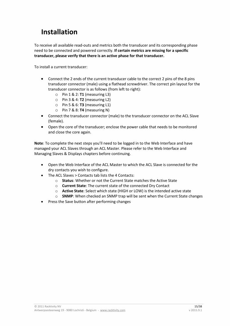
To receive all available read-outs and metrics both the transducer and its corresponding phase need to be connected and powered correctly. If certain metrics are missing for a specific transducer, please verify that there is an active phase for that transducer.
To install a current transducer:
Connect the 2 ends of the current transducer cable to the correct 2 pins of the 8 pins transducer connector (male) using a flathead screwdriver. The correct pin layout for the transducer connector is as follows (from left to right):
o Pin 1 & 2: T1 (measuring L3) o Pin 3 & 4: T2 (measuring L2) o Pin 5 & 6: T3 (measuring L1) o Pin 7 & 8: T4 (measuring N)
Connect the transducer connector (male) to the transducer connector on the ACL Slave (female).
Open the core of the transducer; enclose the power cable that needs to be monitored and close the core again.
Note: To complete the next steps you’ll need to be logged in to the Web Interface and have managed your ACL Slaves through an ACL Master. Please refer to the Web Interface and Managing Slaves & Displays chapters before continuing.
Open the Web Interface of the ACL Master to which the ACL Slave is connected for the dry contacts you wish to configure.
The ACL Slaves > Contacts tab lists the 4 Contacts: o Status: Whether or not the Current State matches the Active State o Current State: The current state of the connected Dry Contact o Active State: Select which state (HIGH or LOW) is the intended active state o SNMP: When checked an SNMP trap will be sent when the Current State changes
Press the Save button after performing changes
© 2011 Racktivity NV 16/38 Antwerpsesteenweg 19 - 9080 Lochristi - Belgium - www.racktivity.com v 2015.9.1
Installing Dry Contacts
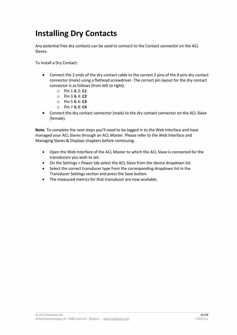
Any potential free dry contacts can be used to connect to the Contact connector on the ACL Slaves.
To install a Dry Contact:
Connect the 2 ends of the dry contact cable to the correct 2 pins of the 8 pins dry contact connector (male) using a flathead screwdriver. The correct pin layout for the dry contact connector is as follows (from left to right):
o Pin 1 & 2: C1 o Pin 3 & 4: C2 o Pin 5 & 6: C3 o Pin 7 & 8: C4
Connect the dry contact connector (male) to the dry contact connector on the ACL Slave (female).
Note: To complete the next steps you’ll need to be logged in to the Web Interface and have managed your ACL Slaves through an ACL Master. Please refer to the Web Interface and Managing Slaves & Displays chapters before continuing.
Open the Web Interface of the ACL Master to which the ACL Slave is connected for the transducers you wish to set.
On the Settings > Power tab select the ACL Slave from the device dropdown list
Select the correct transducer type from the corresponding dropdown list in the Transducer Settings section and press the Save button.
The measured metrics for that transducer are now available.
© 2011 Racktivity NV 17/38 Antwerpsesteenweg 19 - 9080 Lochristi - Belgium - www.racktivity.com v 2015.9.1
Overview
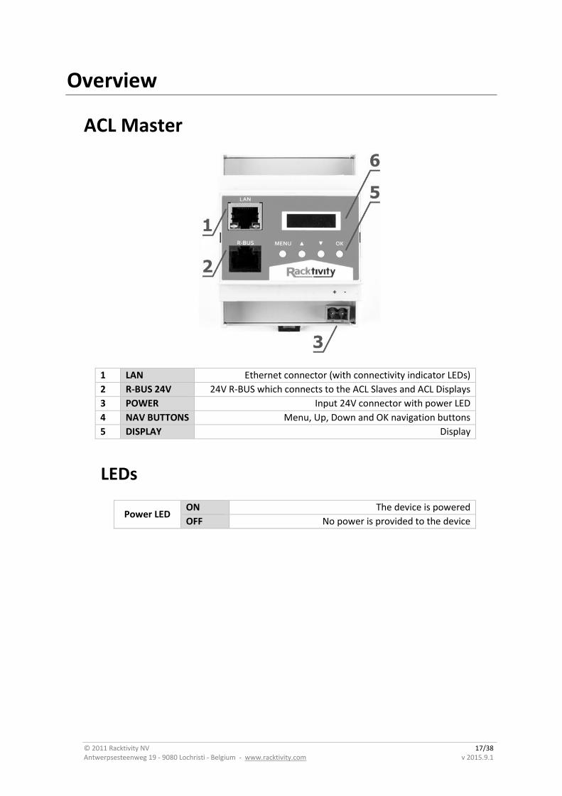
ACL Master
1 LAN Ethernet connector (with connectivity indicator LEDs)
2 R-BUS 24V 24V R-BUS which connects to the ACL Slaves and ACL Displays
3 POWER Input 24V connector with power LED
4 NAV BUTTONS Menu, Up, Down and OK navigation buttons
5 DISPLAY Display
LEDs
Power LED ON The device is powered
OFF No power is provided to the device
© 2011 Racktivity NV 18/38 Antwerpsesteenweg 19 - 9080 Lochristi - Belgium - www.racktivity.com v 2015.9.1
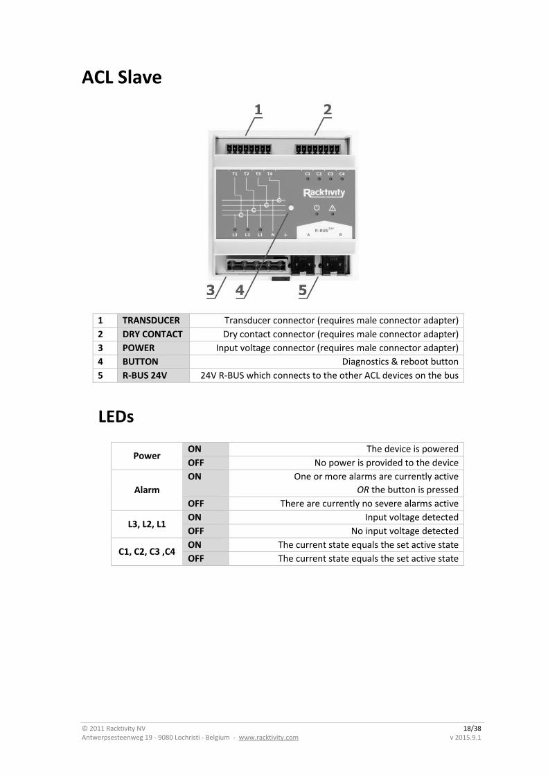
ACL Slave
1 TRANSDUCER Transducer connector (requires male connector adapter)
2 DRY CONTACT Dry contact connector (requires male connector adapter)
3 POWER Input voltage connector (requires male connector adapter)
4 BUTTON Diagnostics & reboot button
5 R-BUS 24V 24V R-BUS which connects to the other ACL devices on the bus
LEDs
Power ON The device is powered
OFF No power is provided to the device
Alarm
ON One or more alarms are currently active
OR the button is pressed
OFF There are currently no severe alarms active
L3, L2, L1 ON Input voltage detected
OFF No input voltage detected
C1, C2, C3 ,C4 ON The current state equals the set active state
OFF The current state equals the set active state
© 2011 Racktivity NV 19/38 Antwerpsesteenweg 19 - 9080 Lochristi - Belgium - www.racktivity.com v 2015.9.1
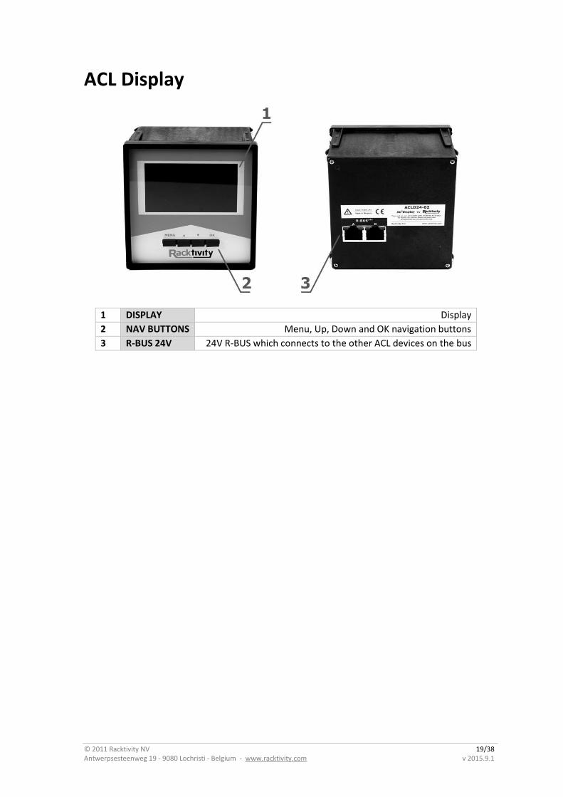
ACL Display
1 DISPLAY Display
2 NAV BUTTONS Menu, Up, Down and OK navigation buttons
3 R-BUS 24V 24V R-BUS which connects to the other ACL devices on the bus
© 2011 Racktivity NV 20/38 Antwerpsesteenweg 19 - 9080 Lochristi - Belgium - www.racktivity.com v 2015.9.1
Quick Configuration
Using the Onboard Display
Activating the Display
Note: The ACL Display’ onboard display doesn’t have an inactive state. Whenever the device is powered the display will show the intended content.
When the Power LED on the ACL Master is lit and the display is black, push any of the 4 navigation buttons next to the display to activate it. The standby delay can be set at the Settings page on the Web Interface (the default value is 10 minutes).
Controlling the Display
The display is controlled using the MENU, UP, DOWN and OK buttons below the screen.
Use the UP and DOWN buttons to navigate through the reporting screens or through a selection list in the menu. Press OK to select the highlighted item and MENU to go back.
© 2011 Racktivity NV 21/38 Antwerpsesteenweg 19 - 9080 Lochristi - Belgium - www.racktivity.com v 2015.9.1
Network Settings
Note: Only the ACL Master provides network access to the devices on the bus. The ACL Slave and ACL Display cannot be managed without an ACL Master connected.
There are two methods for setting up the IP address: Dynamic IP address assignment and Manual Assignment. If you are uncertain which method to use, contact your network administrator for assistance before continuing the installation process.
Note: Recent browser versions have started blocking the SSLv3 encryption protocol used by the device when HTTPS is enabled. For this reason HTTPS has been disabled by default. Please make sure your browser allows SSLv3 prior to updating the HTTP(S) setting.
Dynamic IP Address Assignment (DEFAULT)
1. Press the MENU button until the MENU appears, select Network Settings using the DOWN
button and press OK.
2. Within the Network Settings menu, select DHCP and press OK. When the value DHCP: ON is
displayed, the device already has dynamic IP assignment enabled (skip to step 4).
3. Use the UP button to select Apply Settings and press OK. Press the MENU button to cancel
or the OK button to apply the settings.
4. Press DOWN to select IP Address and press OK to display the current IP address.
Note: The currently active IP address is also shown on the main overview screen
5. On a computer in the same network, use a browser to open the assigned IP address, for
example http://192.168.14.250
6. When surfing to the web portal, a login screen appears. The default user name is admin and
the default password is 1234.
© 2011 Racktivity NV 22/38 Antwerpsesteenweg 19 - 9080 Lochristi - Belgium - www.racktivity.com v 2015.9.1
Manual IP Address Assignment
1. Obtain the correct IP address, standard gateway, DNS Server IP and subnet mask from your
network administrator.
2. Press the MENU button until the MENU appears, select Network Settings using the DOWN
button and press OK.
3. Within the Network Settings menu, select DHCP and press OK. When the value ‘DHCP: OFF’
is displayed, the device already has manual IP assignment enabled. If not, use the UP or
DOWN buttons to change the value to ‘DHCP: OFF’ and press MENU or OK to confirm.
4. Use the UP button to select IP Address and press OK.
5. Use the UP and DOWN buttons to change the currently selected value and press OK to select
the next value. When holding the UP and DOWN buttons, you can speed up the changing of
the values. When ready press MENU to confirm and return to the Network Settings menu.
6. Repeat the last two steps for the Subnet Mask, Standard Gateway and DNS Server settings.
7. Use the UP button to select Apply Settings and press OK. Press the MENU button to cancel
or the OK button to apply the settings.
8. On a computer in the same network, use a browser to open the chosen IP address, for
example http://192.168.14.250
9. When surfing to the web portal, a popup appears requesting a username and password. The default username is admin and the default password is 1234
© 2011 Racktivity NV 23/38 Antwerpsesteenweg 19 - 9080 Lochristi - Belgium - www.racktivity.com v 2015.9.1
Web Interface
Getting Started
Supported Web Browsers
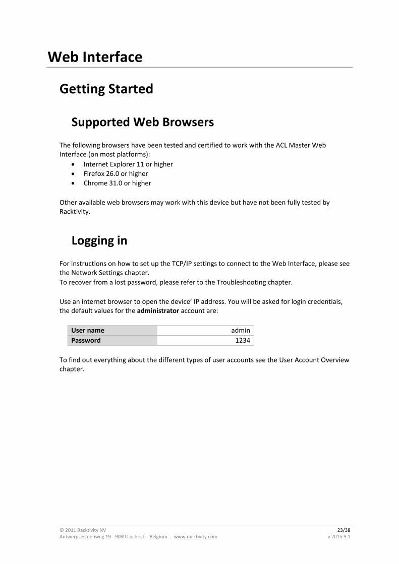
The following browsers have been tested and certified to work with the ACL Master Web Interface (on most platforms):
Internet Explorer 11 or higher
Firefox 26.0 or higher
Chrome 31.0 or higher
Other available web browsers may work with this device but have not been fully tested by Racktivity.
Logging in
For instructions on how to set up the TCP/IP settings to connect to the Web Interface, please see the Network Settings chapter.
To recover from a lost password, please refer to the Troubleshooting chapter.
Use an internet browser to open the device’ IP address. You will be asked for login credentials, the default values for the administrator account are:
User name admin
Password 1234
To find out everything about the different types of user accounts see the User Account Overview chapter.
© 2011 Racktivity NV 24/38 Antwerpsesteenweg 19 - 9080 Lochristi - Belgium - www.racktivity.com v 2015.9.1
Layout
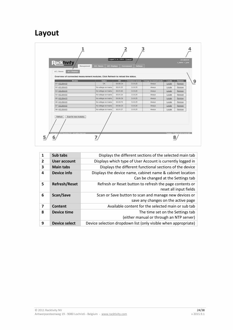
1 Sub tabs Displays the different sections of the selected main tab
2 User account Displays which type of User Account is currently logged in
3 Main tabs Displays the different functional sections of the device
4 Device info Displays the device name, cabinet name & cabinet location Can be changed at the Settings tab
5 Refresh/Reset Refresh or Reset button to refresh the page contents or reset all input fields
6 Scan/Save Scan or Save button to scan and manage new devices or save any changes on the active page
7 Content Available content for the selected main or sub tab
8 Device time The time set on the Settings tab (either manual or through an NTP server)
9 Device select Device selection dropdown list (only visible when appropriate)
© 2011 Racktivity NV 25/38 Antwerpsesteenweg 19 - 9080 Lochristi - Belgium - www.racktivity.com v 2015.9.1
Tabs
Management
The management tab is used to manage the ACL Slaves and ACL Displays.
Each of the subtabs provides an overview of the managed devices and their current status, UID (unique identifier) and firmware version.
Pressing the Locate link next to a device in the list will enhance the visibility of that device:
ACL Slaves: the Dry Contact LEDs will start blinking
ACL Displays: the display will start blinking (as of FW v3.1)
To stop locating the device press the End Locate link or press any button on that device’s front panel.
Whenever a managed device is no longer detected by the ACL Master it will be shown as Disconnected.
For more info on managing devices please refer to the Managing Slaves & Displays chapter.
ACL Slaves
The ACL Slave tab allows you to select every managed Slave device to monitor and manage the following parameters:
Voltage o Current value, historical min & max, thresholds (low & high), phase shift &
frequency
Current o Current value, historical min & max, thresholds (low & high), THD (Total
Harmonic Distortion)
Power o Current value, historical min & max, high threshold, VA (apparent power) &
power factor
Energy o kWh (real energy) & kVAh (apparent energy)
Note: The values in the Accumulated columns cannot be reset to zero by pressing the Reset links, only the values in the Resettable columns.
Contacts o Current state & active state
The Status LED image displays the following statuses:
Grey o Voltage, current, power: There is no incoming voltage on this phase
Orange o Voltage, current, power: One or more metrics on this phase is outside its
threshold boundaries.

© 2011 Racktivity NV 26/38 Antwerpsesteenweg 19 - 9080 Lochristi - Belgium - www.racktivity.com v 2015.9.1
o Contacts: The Current State does not match the Active State for this contact.
Green o Voltage, current, power: The status for this metric is OK. o Contacts: The Current State matches the Active State for this contact.
ACL Displays
When one or more ACL Displays are managed by the ALC Master this tab allows you to set each Display as ‘Display All’ or ‘Display Selected’
Display All When the Display All checkbox is checked all managed ACL Slaves will be available on the selected ACL Display.
Display Selected With the Display All checkbox unchecked it is possible to select which managed ACL Slaves to be available on the selected ACL Display.
Environment
The Environment tab shows the values - and settable thresholds - for the ACL Master’s internal temperature sensor:
Current value
Historical minimum & maximum
Thresholds: low & high
SNMP Traps for temperature
Note: The temperature unit (Celsius or Fahrenheit) can be set on the Settings > Device subtab.
Settings
Use this tab to configure the following settings:
Device (see Device Settings chapter)
Network (see Network Settings chapter)
SNMP (see SNMP Settings chapter)
Power (see Power Settings chapter)
© 2011 Racktivity NV 27/38 Antwerpsesteenweg 19 - 9080 Lochristi - Belgium - www.racktivity.com v 2015.9.1
Device Settings
Path: Settings > Device
The Device Settings give access to:
Device identification o Device name: the name of the device o Rack name: the name of the rack/cabinet where the device is located o Rack position: the identifier of the position in the rack/cabinet
User account settings (see the User Account Overview chapter) o Admin: Name and password for the admin account o Restricted user: Name and password for the restricted account o Guest: Name and password for the guest account
System reboot o Reboot device: Pressing this button will hot reset the device
Display settings o Display timeout: the idle time in minutes after which the ACL Master’s onboard
display goes into standby o Display lock: when enabled, the display (and buttons) cannot be used to change
settings (display becomes read-only). All changes must be made through the other available interfaces
Temperature o Temperature unit: degrees Celsius (°C) or Fahrenheit (°F)
Web Interface o Website auto logout: The time in minutes after which the session expires
Clock settings (see the Network Time Protocol (NTP) chapter) o Date & Time Settings: The real-time clock dialog features several options:
Uncheck the Use NTP checkbox to be able to set a custom date & time Uncheck the Use default NTP checkbox to not use an NTP server from
pool.ntp.org and enter the custom IP address into the NTP address field
Note: Making changes to the date/time settings will clear all Logging!
System info o About this device: Shows all relevant firmware and hardware info regarding your
device and its managed modules. Please provide this info when communication with Racktivity Support.
© 2011 Racktivity NV 28/38 Antwerpsesteenweg 19 - 9080 Lochristi - Belgium - www.racktivity.com v 2015.9.1
Network Settings
Path: Settings > Network
The Network subtab contains the Network and other security settings. The following Network settings are available:
MAC Address o The MAC address of the device
Enable DHCP o Toggle DHCP (depending on this setting the fields below it will be enabled or
disabled)
Device IP Address o The IP address of the device
Subnet Mask o The subnet mask of the device
Standard Gateway o The IP address of the default node on the network
DNS Server o The IP address of the Domain Name System (DNS) server
Test Connection o Ping a device on the network to test network settings.
Note: Save any changed settings before using this functionality.
Force secure web access (HTTPS) o Check to force secure HTTPS web access using SSLv3
Force secure Telnet access (SSL) o Check to force Telnet-SSL access
SNMP Settings
Path: Settings > SNMP
The ACL Master offers SNMPv2c and SNMPv3 communication (GETs, SETs and traps). Notifications (traps) can be enabled or disabled for many of the device’s functions.
For more info on setting SNMP notifications for specific thresholds see the Thresholds chapter.
© 2011 Racktivity NV 29/38 Antwerpsesteenweg 19 - 9080 Lochristi - Belgium - www.racktivity.com v 2015.9.1
The SNMP subtab is divided into 3 sections: Global, Authentication Profiles and Traps.
Global
The Global section of the SNMP subtab contains the following settings:
Allow SNMPv2c GET & SET o Toggles communication to and from the device using SNMPv2c
Note: SNMPv2c Traps can still be used when this setting is disabled (see Traps chapter)
Allow SNMPv3 GET & SET o Toggles communication to and from the device using SNMPv3
Note: SNMPv3 Traps can still be used when this setting is disabled (see Traps chapter)
Write Protection (SNMP read-only) o With this setting enabled the device will not accept changes and SET requests
over SNMPv2c or SNMPv3. GET, Walk, etc. requests are still allowed
Enable SNMP Traps o When enabled, no SNMP Traps will be sent (even when all other SNMP settings
are configured correctly)
Heartbeat Interval o Defines the interval (in seconds) at which Heartbeat SNMP Traps will be sent to
the configured receivers. Set to 0 to disable this feature
Download MIB file o The MIB files for your device, more info in the Error! Reference source not
ound. chapter
Authentication Profiles
The authentication profiles section is used to configure the available SNMP profiles for GET & SET access. At this time the following profiles are available:
SNMPv2c o 1 profile available o Requires community strings (read, write and trap)
SNMPv3 o 3 profiles available o The SNMPv3 profiles require all of the following parameters:
USM User Authentication passphrase (auth): MD5
In text or hexadecimal format Privacy passphrase (priv): AES
In text or hexadecimal format
Note: Some SNMP monitoring tools will require the SNMPv3 Engine ID displayed in this section.
© 2011 Racktivity NV 30/38 Antwerpsesteenweg 19 - 9080 Lochristi - Belgium - www.racktivity.com v 2015.9.1
Traps
In the Traps section up to 3 SNMP Trap receivers can be configured. Each receiver contains the following:
Enable o Enable or disable this receiver
IP Address o The IP address of the receiver
Port o The network port on the receiver to use
Authentication profile o The authentication profile used to authenticate with the Trap receiver
Send test SNMP Trap o Sends a Heartbeat Trap to all configured SNMP Trap receivers
Note: Save any changed settings before using the button Note: This button is disabled when SNMP Traps are disabled in the Global section
Power Settings
Path: Settings > Power
Note: Use the module selection dropdown list to select the correct ACL Slave.
The Power tab allows you to set the following for each managed ACL Slave:
Energy Increment Mode The energy increment mode determines how the values on the ACL Slave > Energy tab are calculated
o Always: All values will be incremented to calculate the energy o Only Positive: Only positive values will be incremented to calculate the energy o Only Negative: Only negative values will be incremented to calculate the energy
Transducer Settings Select the correct transducer type from the dropdown list for each of the connected transducers (T1, T2, T3 and T4). The transducer type is printed on the model label of each transducer. Note: Selecting an incorrect type of transducer will return incorrect values on the ACL Slave tab.
At the time of writing current sensors with the following Amp rating are available for purchase from Racktivity:
25A
50A
100A
200A
400A
600A
800A
1500A
2000A
3000A
Please contact [email protected] for an updated list or more information.
© 2011 Racktivity NV 31/38 Antwerpsesteenweg 19 - 9080 Lochristi - Belgium - www.racktivity.com v 2015.9.1
Managing Slaves & Displays
In order to fully use the ACL Slaves and ACL Displays they need to be managed by the ACL Master.
1. Make sure the ACL Slaves and ACL Displays are connected and powered correctly. Please refer to the Mounting the ACL Hardware chapter for more info.
2. On the ACL Master Web Interface, open the Management > ACL Slaves or ACL Displays tab.
3. Press the Scan for New Modules button.
4. After scanning has completed verify that the connected devices are listed in the table.
5. The management table shows basic info on each device allows you to locate and/or remove certain units.
6. All devices listed (for both ACL Slaves and ACL Displays) are now available on the Web Interface of this ACL Master, use the device selection dropdown list on the relevant tabs to switch devices (see the Layout chapter).
Principles
Whenever Slaves or Displays are added to the R-BUS24V and managed by the Master the addressing of that module will follow the rules below:
1. New modules will get the next available (unused) module address.
2. As long as a managed module is not explicitly removed (by pressing the corresponding Remove link on its management tab, or by performing a factory reset) that address will remain reserved for that module.
Let’s say you start with the following setup:
Q1: managed & connected
Q2: managed & disconnected
D3: managed & connected
Q4: managed & connected
Based on the 1st Principle, any new module that is connected and managed will be assigned address 5 (either Q5 or D5, depending on the type of module).
Based on the 2nd Principle, if you however remove the disconnected module (Q2) first, and then connect and manage a new module it will be assigned address 2 (either Q2 or D2, depending on the type of module).
Note that a module does not need to be disconnected before it can be removed.
© 2011 Racktivity NV 32/38 Antwerpsesteenweg 19 - 9080 Lochristi - Belgium - www.racktivity.com v 2015.9.1
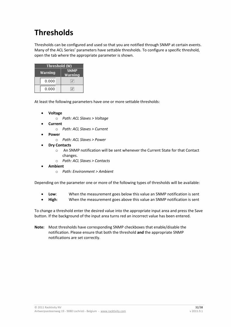
Thresholds
Thresholds can be configured and used so that you are notified through SNMP at certain events. Many of the ACL Series’ parameters have settable thresholds. To configure a specific threshold, open the tab where the appropriate parameter is shown.
At least the following parameters have one or more settable thresholds:
Voltage o Path: ACL Slaves > Voltage
Current o Path: ACL Slaves > Current
Power o Path: ACL Slaves > Power
Dry Contacts o An SNMP notification will be sent whenever the Current State for that Contact
changes. o Path: ACL Slaves > Contacts
Ambient o Path: Environment > Ambient
Depending on the parameter one or more of the following types of thresholds will be available:
Low: When the measurement goes below this value an SNMP notification is sent
High: When the measurement goes above this value an SNMP notification is sent
To change a threshold enter the desired value into the appropriate input area and press the Save button. If the background of the input area turns red an incorrect value has been entered.
Note: Most thresholds have corresponding SNMP checkboxes that enable/disable the notification. Please ensure that both the threshold and the appropriate SNMP notifications are set correctly.
© 2011 Racktivity NV 33/38 Antwerpsesteenweg 19 - 9080 Lochristi - Belgium - www.racktivity.com v 2015.9.1
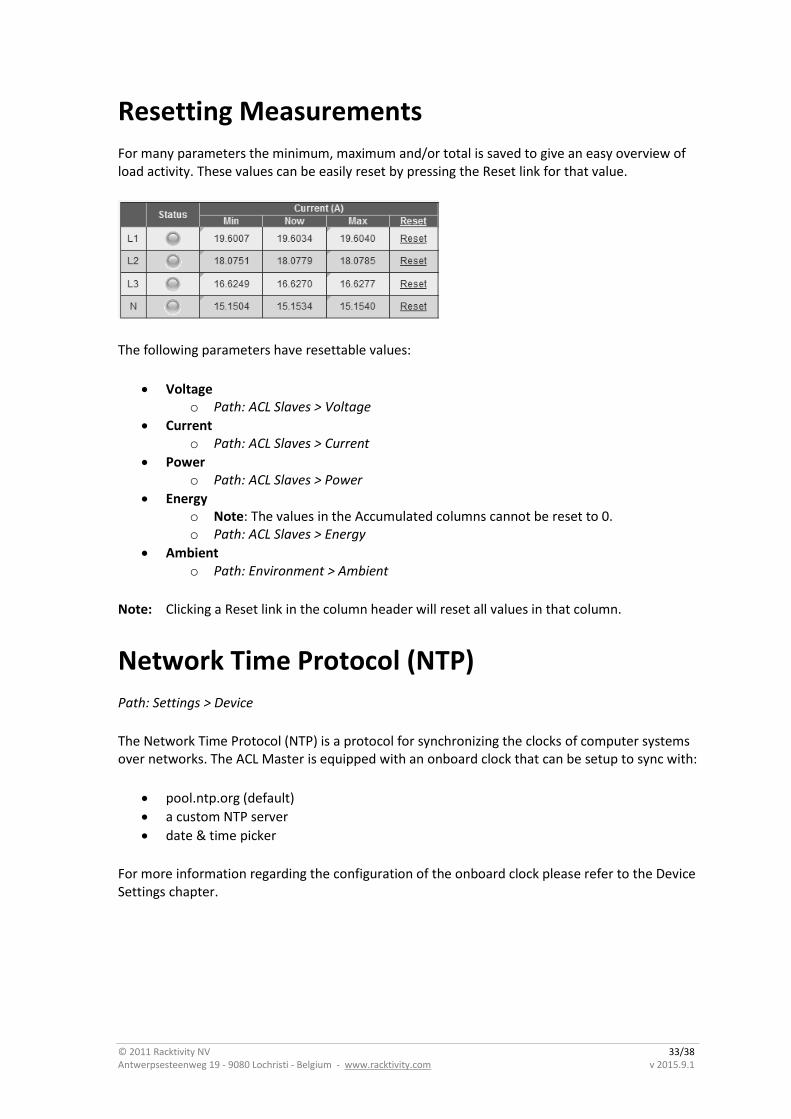
Resetting Measurements
For many parameters the minimum, maximum and/or total is saved to give an easy overview of load activity. These values can be easily reset by pressing the Reset link for that value.
The following parameters have resettable values:
Voltage o Path: ACL Slaves > Voltage
Current o Path: ACL Slaves > Current
Power o Path: ACL Slaves > Power
Energy o Note: The values in the Accumulated columns cannot be reset to 0. o Path: ACL Slaves > Energy
Ambient o Path: Environment > Ambient
Note: Clicking a Reset link in the column header will reset all values in that column.
Network Time Protocol (NTP)
Path: Settings > Device
The Network Time Protocol (NTP) is a protocol for synchronizing the clocks of computer systems over networks. The ACL Master is equipped with an onboard clock that can be setup to sync with:
pool.ntp.org (default)
a custom NTP server
date & time picker
For more information regarding the configuration of the onboard clock please refer to the Device Settings chapter.
© 2011 Racktivity NV 34/38 Antwerpsesteenweg 19 - 9080 Lochristi - Belgium - www.racktivity.com v 2015.9.1
CLI
Introduction
The ACL Master has a built in Command Line Interface that can be accessed through Telnet or secure Telnet (Telnet-SSL). Commands are typically sent to the separate modules. An ACL Series setup consists of 1 Master module, up to 32 ACL Slaves, and up to 7 ACL Displays.
Each device is designated as a specific type:
M for the ACL Master
Q for the ACL Slaves
D for the ACL Displays
The Master will always have address M1 while the Slaves will have address Q1 to Q32 (same for the Displays)
Connecting
Telnet Connect to the device IP on port 23 over Telnet using a 3rd party tool (i.e. Putty). Please note that only Telnet over SSL is enabled by default. This can be changed on the Settings > Network subtab on the Web Interface of the ACL Master.
Telnet-SSL Connecting to Telnet over SSL can be achieved through several 3rd party tools. For example using stunnel (cross platform):
Create a config file for stunnel called stunnel.conf containing the following:
fips = no cert = stunnel .pem client = yes [pdu] accept = 127.0.0.1:23 connect = [DEVICE_IP]:992 sslVersion = SSLv3 (with [DEVICE_IP] being the IP address of the PDU)
Start stunnel with this config: # stunnel stunnel.conf
If you now Telnet to 127.0.0.1 on port 23, stunnel will tunnel the traffic over SSL to the specified IP.
Once connected, you will be presented with a log-in screen. Use the admin credentials to gain full access. From here it is possible to access the majority of the devices’s functions.
Execute the HELP command for more information.
© 2011 Racktivity NV 35/38 Antwerpsesteenweg 19 - 9080 Lochristi - Belgium - www.racktivity.com v 2015.9.1
Management Information Base (MIB) A Management Information Base (MIB) is a virtual database used for managing the entities in a communications network and is most often associated with the Simple Network Management Protocol (SNMP). The ACL Master features a built-in mib file which can be found at the following locations:
By browsing to http://[DEVICE_IP]/RACKTIVITY-MIB.txt
o with [DEVICE_IP] the IP of your ACL Master
By clicking the "Download MIB file" link on the Settings > SNMP tab on the web portal.
Use this file to translate the OIDs (Object IDentifiers) to a more human-readable state. For more information on how to use the MIB file, please refer to the documentation of your network monitoring software.
© 2011 Racktivity NV 36/38 Antwerpsesteenweg 19 - 9080 Lochristi - Belgium - www.racktivity.com v 2015.9.1
Upgrade Firmware Racktivity is always working on improving and fine-tuning its products. It is possible that a new firmware is available for your device. During a firmware update the device continues working as normal.
Note: Make sure all active connections to the ACL Master - such as the web interface and Telnet - are closed before updating. Open connections might result in a failed update!
Obtaining Files
If you are unsure whether a firmware update is available for your device, have a look at http://www.racktivity.com/support or contact Racktivity Support (see Support chapter).
If applicable the necessary files and instructions will be provided.
© 2011 Racktivity NV 37/38 Antwerpsesteenweg 19 - 9080 Lochristi - Belgium - www.racktivity.com v 2015.9.1
Troubleshooting
Resetting Login Credentials
In case of lost login credentials, resetting them can be done through the navigation buttons on the ACL Master front panel:
Press and hold the UP and DOWN buttons simultaneously for 3 seconds until a notification is shown on the display. The credentials will now be reset to their default settings:
Default login credentials
User name admin
Password 1234
Connecting to the Web Interface
If you are unable to connect to the Web Interface please try one or more of the following options:
Ping the device on its IP address. When unsuccessful, the ACL Master is most likely not on the same network as your PC, or communication is blocked by a network device.
Connect the ACL Master directly to your computer (please note that for this both devices need to have a valid fixed IP).
Try opening the Web Interface with another browser.
Connect to the ACL Master using a different computer.
Power cycle the ACL Master (if possible).
Knowing your device’s IP address
The IP address of your ACL Master is displayed on the main screen of its onboard display. Press any of the navigation buttons to activate the screen.

© 2011 Racktivity NV 38/38 Antwerpsesteenweg 19 - 9080 Lochristi - Belgium - www.racktivity.com v 2015.9.1
Support Feel free to contact us if you need any support or have any other questions or remarks:
Online www.racktivity.com/support
E-mail [email protected]
Phone 003293242095 (GMT+1)