Embed Size (px)
Citation preview
USER INSTRUCTIONS
Installation
Operation
Maintenance
PMV PS/PM Ultraswitch™Switchbox
FCD PMENIM0008-03 A5 - 09/16
2
1. GENERAL INFORMATION .................................................................................... 3
2. SAFETY INSTRUCTION ....................................................................................... 3
3. UNPACKING .................................................................................................... 3
4. CERTIFICATES ................................................................................................. 4
5. SPECIFICATIONS .............................................................................................. 45.1 Technical data .................................................................................................................................45.2 Materials of construction ................................................................................................................45.3 Type sign .........................................................................................................................................45.4 PS/PM UltraSwitch™ nomenclature ...............................................................................................55.5 PS/PM UltraSwitch™ switch options ..............................................................................................6
6. INSTALLATION ................................................................................................ 86.1 Wiring instructions .........................................................................................................................9
7. SWITCHES (Certified) ....................................................................................... 107.1 ATEX EEx e mb certificate info ......................................................................................................107.2 Installation in hazardous locations ................................................................................................107.3 Adjusting limit switches ................................................................................................................107.4 Cam fine adjustment ....................................................................................................................117.5 Adjusting UltraDome™ position indicator .....................................................................................117.6 Calibrating 4-20 mA transmitter ....................................................................................................117.7 Switch option specifications (all) ..................................................................................................127.8 Analog feedback option specifications ..........................................................................................13
8. DIMENSIONS ................................................................................................. 14
9. SPARE PARTS ................................................................................................ 15
CONTENTS
FCD PMENIM0008-03 A5 - 09/16
3
1. GENERAL INFORMATIONPSPM Ultraswitch™ enclosures provide local and remote position indication for automated valves. They generally feature a visual black/yellow or red/green indicator for intuitive local position determination. The PSPM Ultraswitch™ is available with a number of limit switch options for remote indication, in a variety of electrical applications. They may also be used as a junction box for direct installation of solenoid valves.
2. SAFETY INSTRUCTIONRead the safety instructions in this manual carefully before using the product. If any questions arise during installation, contact supplier/sales office before continue working.
This equipment is suitable for use in class (as applicable), division 2, groups (as applicable) or non-hazardous locations only.
Report transport damage to the carrier immediately. In case of discrepancies - contact your nearestFLOWSERVE location.
3. UNPACKING
• Substitution of components may impair suitability for Div. 2 locations.
• Inspect periodically for degradation. Replace parts if degradation is found.
• Cleaning this housing by rubbing should be done in a non-hazardous area.
• Potential electrostatic charging hazard, clean only with a damp cloth – danger of propagating discharge.
• All grounding and bonding installation require-ments must be addressed.
• Pay attention to personal protection, (clothing, glasses, gloves) when performing installation or service.
• Use only Flowserve original spare parts not to invalidate certification.
• All installation, inspection, and maintenance of the equipment should be performed by suitably trained personnel. In addition, for ATEX, all installation, inspection, maintenance and repair must be done by suitably trained personnel. For more informa-tion refer to EN 60079-14:1997, EN 60079-17, EN 60079-18, EN 60079-19.
• For ATEX Ex e mb certified units the unit must also be placed in an area where it is low risk of mechanical danger.
• Do not disconnect equipment unless area is known to be non-hazardous.
• To prevent ignition of flammable or combustible atmospheres, disconnect power before servicing.
FCD PMENIM0008-03 A5 - 09/16
4
4. CERTIFICATESATEX II 1G Ex ia IIC T4/T5/T6IEC Ex ia IIC T4/T5/T6ATEX II 2 G Ex e mb IIC T6cFMus IS Class I,II,III Division 1 Group A,B,C,D,E,F,G cFMus NI Class I Division 2 Group A,B,C,D; Class II Division 2 Group E,F,G; Class III Division 1&2 cCSAus Class I, Division 1 Groups A,B,C,D; Class II Division 1 Groups E,F,G; Classs IIIcCSAus Class I, Division 2, Groups A,B,C,D; Class II, Division 2, Groups E,F,G; Class III
All certificates available for download at www.pmv.nu
5. SPECIFICATIONS5.1 Technical dataIngress protection IP66 & Type 4x Weight 1 kg / 2.2 lbs
5.2 Materials of constructionPart MaterialHousing/Cover PA6/PA66 Nylon 25% - 33% Glass Filled Engineered Resin Shaft Stainless SteelCams/Splines NylonTerminal Block Nylon – Buchanan TBS SeriesInternal Brackets Stainless Steel or Plated SteelAll Internal Fasteners Stainless Steel or Plated SteelAll External Fasteners Stainless SteelAll Molded in Fasteners Anodized AluminumUltraDome™ PolycarbonateRotor Polycarbonate
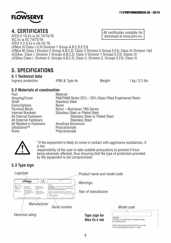
5.3 Type sign
Product name and model code
Warnings
Year of manufactureS/N: XXXXXX
Manufacturer
Electrical rating
Serial number
Logotype
WARNINGPOTENTIAL ELECTROSTATIC CHARGING HAZARDSEE INSTRUCTIONS
POWER SOURCE MUST BE PROTECTED BY A FUSEOF 3 A WITH BREAKING CAPACITY ≥ 1500A
Model code
Type sign for Atex Ex e mb
PALMSTIERNA INTERNATIONAL AB, SOLNA, SWEDEN
S/N:
IP 66/Type 4X
DATE:
0470
Cl. I Div.2 Gr. A-D T6Cl. I Div.2 Gr.A-D T4-6Cl. II Div.2 Gr. E-G
Cl. I Div.1 Gr.A-D T5Cl. II Div.1 Gr. E-GCl. III
NON INCENDIVE
Cl. II Div.2 Gr. E-G T6
II 1 G
11ATEX1065X NEMKO Ex ia IIC T4-T6 Gb
REFERENCE TO CONTROL DWG NO. RA-2 FOR SAFE USE
SAFTY AND SUITABILITY FOR DIVITION 2.Div. 1,Gr A-G,T4-T6CLASS I,II&IIIINTRINSIC SAFY
SUBSTITUTION OF COMPONENTS MAY IMPAIR INSTRINSIC
Cl.III Div.1&2
WARNING:
POTENTIONAL ELECTROSTATIC CHARGING HAZARD- SEE INSTRUCTIONS.
INTRINSIC SAFY
NON INCENDIVEIECEx NEM 11.0012X
*If the equipment is likely to come in contact with aggressive substances, it is the responsibility of the user to take suitable precautions to prevent it from being adversely affected, thus ensuring that the type of protection provided by the equipment is not compromised.
FCD PMENIM0008-03 A5 - 09/16FCD PMENIM0008-02 - 08/14
5
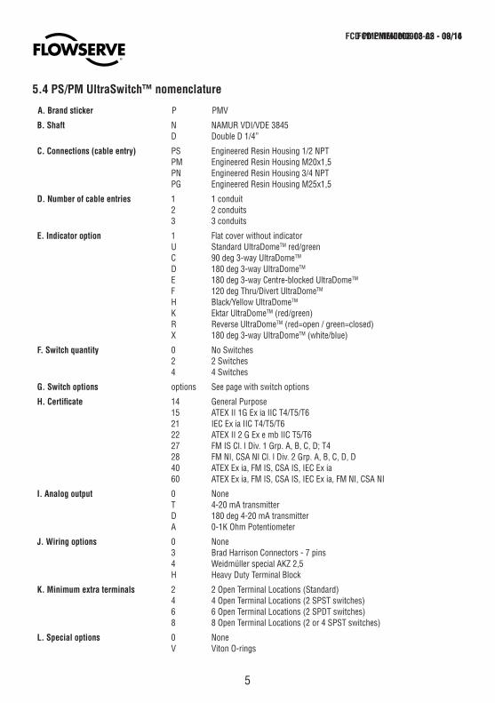
5.4 PS/PM UltraSwitch™ nomenclature
FCD PMENIM0008-03 A5 - 09/16
A. Brand sticker P PMV
B. Shaft N NAMUR VDI/VDE 3845D Double D 1/4”
C. Connections (cable entry) PS Engineered Resin Housing 1/2 NPTPM Engineered Resin Housing M20x1,5PN Engineered Resin Housing 3/4 NPTPG Engineered Resin Housing M25x1,5
D. Number of cable entries 1 1 conduit2 2 conduits3 3 conduits
E. Indicator option 1 Flat cover without indicatorU Standard UltraDomeTM red/greenC 90 deg 3-way UltraDomeTM
D 180 deg 3-way UltraDomeTM
E 180 deg 3-way Centre-blocked UltraDomeTM
F 120 deg Thru/Divert UltraDomeTM
H Black/Yellow UltraDomeTM
K Ektar UltraDomeTM (red/green)R Reverse UltraDomeTM (red=open / green=closed)X 180 deg 3-way UltraDomeTM (white/blue)
F. Switch quantity 0 No Switches2 2 Switches4 4 Switches
G. Switch options options See page with switch options
H. Certificate 14 General Purpose15 ATEX II 1G Ex ia IIC T4/T5/T621 IEC Ex ia IIC T4/T5/T622 ATEX II 2 G Ex e mb IIC T5/T627 FM IS Cl. l Div. 1 Grp. A, B, C, D; T428 FM NI, CSA NI Cl. l Div. 2 Grp. A, B, C, D, D40 ATEX Ex ia, FM IS, CSA IS, IEC Ex ia60 ATEX Ex ia, FM IS, CSA IS, IEC Ex ia, FM NI, CSA NI
I. Analog output 0 NoneT 4-20 mA transmitterD 180 deg 4-20 mA transmitterA 0-1K Ohm Potentiometer
J. Wiring options 0 None3 Brad Harrison Connectors - 7 pins4 Weidmüller special AKZ 2,5H Heavy Duty Terminal Block
K. Minimum extra terminals 2 2 Open Terminal Locations (Standard)4 4 Open Terminal Locations (2 SPST switches)6 6 Open Terminal Locations (2 SPDT switches)8 8 Open Terminal Locations (2 or 4 SPST switches)
L. Special options 0 NoneV Viton O-rings
FCD PMENIM0008-02 - 08/14
6
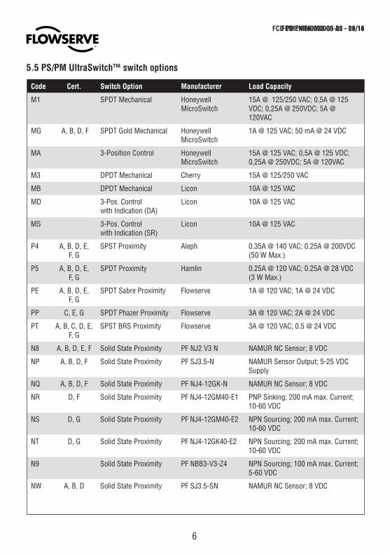
5.5 PS/PM UltraSwitch™ switch options
Code Cert. Switch Option Manufacturer Load Capacity
M1 SPDT Mechanical Honeywell MicroSwitch
15A @ 125/250 VAC; 0,5A @ 125 VDC; 0,25A @ 250VDC; 5A @ 120VAC
MG A, B, D, F SPDT Gold Mechanical Honeywell MicroSwitch
1A @ 125 VAC; 50 mA @ 24 VDC
MA 3-Position Control Honeywell MicroSwitch
15A @ 125 VAC; 0,5A @ 125 VDC; 0,25A @ 250VDC; 5A @ 120VAC
M3 DPDT Mechanical Cherry 15A @ 125/250 VAC
MB DPDT Mechanical Licon 10A @ 125 VAC
MD 3-Pos. Control with Indication (DA)
Licon 10A @ 125 VAC
MS 3-Pos. Control with Indication (SR)
Licon 10A @ 125 VAC
P4 A, B, D, E, F, G
SPST Proximity Aleph 0.35A @ 140 VAC; 0.25A @ 200VDC (50 W Max.)
P5 A, B, D, E, F, G
SPDT Proximity Hamlin 0.25A @ 120 VAC; 0.25A @ 28 VDC (3 W Max.)
PE A, B, D, E, F, G
SPDT Sabre Proximity Flowserve 1A @ 120 VAC; 1A @ 24 VDC
PP C, E, G SPDT Phazer Proximity Flowserve 3A @ 120 VAC; 2A @ 24 VDC
PT A, B, C, D, E, F, G
SPST BRS Proximity Flowserve 3A @ 120 VAC; 0.5 @ 24 VDC
N8 A, B, D, E, F Solid State Proximity PF NJ2 V3 N NAMUR NC Sensor; 8 VDC
NP A, B, D, F Solid State Proximity PF SJ3.5-N NAMUR Sensor Output; 5-25 VDC Supply
NQ A, B, D, F Solid State Proximity PF NJ4-12GK-N NAMUR NC Sensor; 8 VDC
NR D, F Solid State Proximity PF NJ4-12GM40-E1 PNP Sinking; 200 mA max. Current; 10-60 VDC
NS D, G Solid State Proximity PF NJ4-12GM40-E2 NPN Sourcing; 200 mA max. Current; 10-60 VDC
NT D, G Solid State Proximity PF NJ4-12GK40-E2 NPN Sourcing; 200 mA max. Current; 10-60 VDC
N9 Solid State Proximity PF NBB3-V3-Z4 NPN Sourcing; 100 mA max. Current; 5-60 VDC
NW A, B, D Solid State Proximity PF SJ3.5-SN NAMUR NC Sensor; 8 VDC
FCD PMENIM0008-03 A5 - 09/16FCD PMENIM0008-02 - 08/14
7
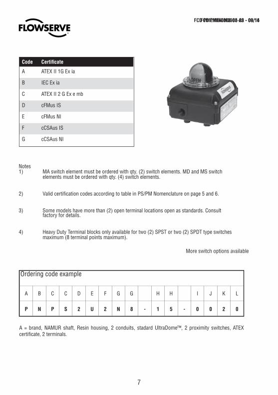
A = brand, NAMUR shaft, Resin housing, 2 conduits, stadard UltraDome™, 2 proximity switches, ATEX certificate, 2 terminals.
Notes1) MA switch element must be ordered with qty. (2) switch elements. MD and MS switch elements must be ordered with qty. (4) switch elements.
2) Valid certification codes according to table in PS/PM Nomenclature on page 5 and 6.
3) Some models have more than (2) open terminal locations open as standards. Consult factory for details.
4) Heavy Duty Terminal blocks only available for two (2) SPST or two (2) SPDT type switches maximum (8 terminal points maximum).
Code Certificate
A ATEX II 1G Ex ia
B IEC Ex ia
C ATEX II 2 G Ex e mb
D cFMus IS
E cFMus NI
F cCSAus IS
G cCSAus NI
FCD PMENIM0008-03 A5 - 09/16FCD PMENIM0008-02 - 08/14
Ordering code example
A B C C D E F G G H H I J K L
P N P S 2 U 2 N 8 - 1 5 - 0 0 2 0
More switch options available

8
PS/PM switch mounted on rotary actuator
PS/PM switch mounted on linear actuator
Hex. screws M5 x 8
6. InstallationThe PS/PM Ultraswitch™ may be installed to val-ves or valve actuators with a variety of mounting hardware.
For best results, specify the NAMUR shaft option and NAMUR mounting hardware when installing to NAMUR compliant actuator. These options allow direct coupling to actuators without couplings, reducing dead band.
Simply bolt bracket to actuator and PS/PM Ultraswitch™ to bracket, leaving bolts finger tight.
For NAMUR applications the PS/PM Ultraswitch™ switch shaft features an integral alignment pin. This pin must engage the tapped hole in the actuator shaft.
For non-NAMUR applications, make sure to properly install a coupler between the PS/PM Ultraswitch™ and actuator. Once the PS/PM Ultras-witch™ is installed with fasteners loosely tightened, stroke the actuator two or three times to align the bracket. Then tighten all fasteners.
Ambient temperature working conditionsThe PS/PM Ultraswitch™ switch box is tested and operational in following temperature range:
-40° – 180°F -40° – 80°C
Special conditions for safe use• The Rotary Limit Switch Box is marked with the following warning marking: ”WARNING –POTENTIAL ELECTROSTATIC CHARGING HA-ZARD – SEE INSTRUCTIONS”.
• The total electrical ratings must not exceed the values indicated in this Schedule.
• For nomenclature breakdown please see the installation instructions.
FCD PMENIM0008-03 A5 - 09/16FCD PMENIM0008-02 - 08/14
9
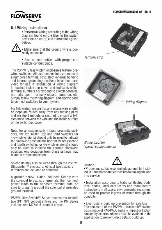
6.1 Wiring instructions• Perform all wiring according to the wiring diagram found on the label in the switch cover (see picture) and instructions given below.
• Make sure that the ground wire is cor-rectly connected
• Seal unused entries with proper and suitable conduit plugs.
The PS/PM Ultraswitch™ enclosures feature pre-wired switches. All user connections are made at a numbered terminal strip. Both external bonding and internal grounding locations have been pro-vided for use in installation. A wiring diagram is located inside the cover and indicates which terminal numbers correspond to switch contacts: normally open, normally closed, common, etc. Simply follow the wiring diagram, and electric code to connect switches to your system.
For field wiring: ensure that any excess wire lengths or loops are routed away from any moving parts and are short enough, or secured to ensure a 1/4” clearance between the wire and the inside surface of the switchbox cover.
Note: for all magnetically tripped proximity swit-ches, the top switch (top and third switches for 4-switch versions) should only be used to indicate the clockwise position: the bottom switch (second and fourth switches for 4-switch versions) should only be used to indicate the counter-clockwise position. Any deviation from these settings may result in erratic indication.
Solenoids may also be wired through the PS/PMUltraswitch™ enclosure. At least two auxiliary terminals are included as standard.
A ground screw is also included. Simply wire the solenoid to auxiliary terminals, then connect power leads to the opposite terminal side. be sure to properly ground the solenoid at provided ground terminal.
PS/PM UltraSwitch™ Series enclosures include two 3⁄4” NPT conduit entries and the PM Series includes two M25x1.5 conduit entries.
Terminal strip
Caution!• Proper and suitable conduit plugs must be instal-led in unused conduit entries before taking the unit into service.
• Installation according to National Electric Code, local codes, local certificates and manufacture instructions in all cases. Environmental seals must be used to protect ingress of water through the conduits.
• Electrostatic build up prevention for safe UseThe enclosure of the PS/PM Ultraswitch™ switch box is made of PA6/PA66 and any impact or friction caused by external objects shall be avoided in the application to prevent electrostatic build up.
Wiring diagram
Wiring diagram(special configurations)
FCD PMENIM0008-03 A5 - 09/16FCD PMENIM0008-02 - 08/14
10
Substitution of components may impair suitability for hazardous (classified) locations. Do not disconnect equipment unless area is known to be non-hazardous.
To prevent ignition of flammable or combustible atmospheres, disconnect power before ser-vicing, or; read, understand and adhere to the manufacturer’s live maintenance procedures.
7. Switches (certified)
7.1 ATEX Ex e mb certificate informationModel code:xxxxxxxPP-22-xxxx or xxxxxxPx2xxxxx: 60VDC 3A 100VAxxxxxxxPT-22-xxxx or xxxxxxTx2xxxxx: 24VDC 3A 75VA NEMKO 12ATEX1079X, IP66 Ex II 2GEx e mb IIC T5 (T6) GbT5 : -40°C ≤ Ta≤ +80°C, T6 : -40°C ≤ Ta≤ +60°C Power source must be protected by a fuse of 3A with a breaking capacity of ≥ 1500A. For ATEX and IECEx installations an appropriately rated gland is required. Any unused conduit entry must have a suitable rated blanking element.
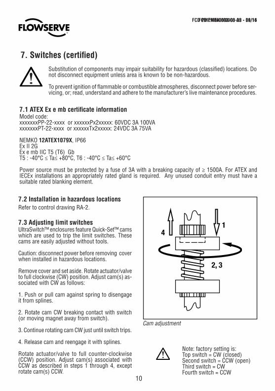
7.3 Adjusting limit switchesUltraSwitch™ enclosures feature Quick-Set™ cams which are used to trip the limit switches. These cams are easily adjusted without tools.
Caution: disconnect power before removing cover when installed in hazardous locations. Remove cover and set aside. Rotate actuator/valve to full clockwise (CW) position. Adjust cam(s) as-sociated with CW as follows:
1. Push or pull cam against spring to disengage it from splines.
2. Rotate cam CW breaking contact with switch (or moving magnet away from switch).
3. Continue rotating cam CW just until switch trips.
4. Release cam and reengage it with splines.
Rotate actuator/valve to full counter-clockwise (CCW) position. Adjust cam(s) associated with CCW as described in steps 1 through 4, except rotate cam(s) CCW.
Cam adjustment
7.2 Installation in hazardous locations Refer to control drawing RA-2.
Note: factory setting is: Top switch = CW (closed) Second switch = CCW (open) Third switch = CW Fourth switch = CCW
FCD PMENIM0008-03 A5 - 09/16FCD PMENIM0008-02 - 08/14
11
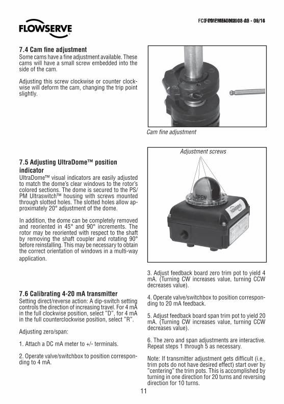
Adjustment screws
Cam fine adjustment
7.4 Cam fine adjustmentSome cams have a fine adjustment available. These cams will have a small screw embedded into the side of the cam.
Adjusting this screw clockwise or counter clock-wise will deform the cam, changing the trip point slightly.
7.5 Adjusting UltraDome™ position indicatorUltraDome™ visual indicators are easily adjusted to match the dome’s clear windows to the rotor’s colored sections. The dome is secured to the PS/PM Ultraswitch™ housing with screws mounted through slotted holes. The slotted holes allow ap-proximately 20° adjustment of the dome.
In addition, the dome can be completely removed and reoriented in 45° and 90° increments. The rotor may be reoriented with respect to the shaft by removing the shaft coupler and rotating 90° before reinstalling. This may be necessary to obtain the correct orientation of windows in a multi-way application.
7.6 Calibrating 4-20 mA transmitterSetting direct/reverse action: A dip-switch setting controls the direction of increasing travel. For 4 mA in the full clockwise position, select ”D”, for 4 mA in the full counterclockwise position, select ”R”.
Adjusting zero/span:
1. Attach a DC mA meter to +/- terminals.
2. Operate valve/switchbox to position correspon-ding to 4 mA.
3. Adjust feedback board zero trim pot to yield 4 mA. (Turning CW increases value, turning CCW decreases value).
4. Operate valve/switchbox to position correspon-ding to 20 mA feedback.
5. Adjust feedback board span trim pot to yield 20 mA. (Turning CW increases value, turning CCW decreases value).
6. The zero and span adjustments are interactive. Repeat steps 1 through 5 as necessary.
Note: If transmitter adjustment gets difficult (i.e., trim pots do not have desired effect) start over by ”centering” the trim pots. This is accomplished by turning in one direction for 20 turns and reversing direction for 10 turns.
FCD PMENIM0008-03 A5 - 09/16FCD PMENIM0008-02 - 08/14
12
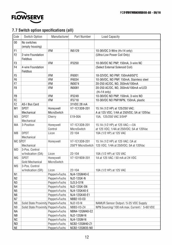
00 No switches (empty housing) F1 IFM IN5129 10-36VDC 3-Wire (H=14 only) F2 2-wire Foundation (Ultra-Low Power Coil Only) Fieldbus F3 IFM IF5250 10-36VDC NC PNP, 150mA, 3-wire NCF4 4-wire Foundation (Select External Solenoid Coil) Fieldbus F5 IFM IF6001 18-32VDC, NO PNP, 150mA@50°CF6 IFM IF6034 10-36VDC, NO PNP, 150mA, Stainless steelF7 IFM IN0074 20-250 AC/DC, NO, 350mA/100mAF8 IFM IN0081 20-250 AC/DC, NO, 350mA/100mA w/LED (H=14 only)FB IFM IF5249 10-36VDC NO PNP, 150mA, 3-wire NOFC IFM IF5718 10-36VDC NO PNP/NPN, 150mA, plastic FZ AS-I Bus Card 31VDC 28 mAM1 SPDT Honeywell V7-1C13D8-201 15.1A (1/2 HP) at 125/250 VAC; Mechanical MicroSwitch A at 125 VDC; 1/4A at 250VDC; 5A at 120VacM3 DPDT Cherry E19-00A 15A, 125/250 VAC 3/5HP MechanicalMA 3-Position Honeywell V7-1C13D8-201 15.1A (1/2 HP) at 125 VAC;—ΩA Control MicroSwitch at 125 VDC; 1/4A at 250VDC; 5A at 120VacMB DPDT Licon 22-104 10A (1/2 HP) at 125 VAC Mechanical MC SPDT Honeywell V7-1C13D8-201 15.1A (1/2 HP) at 125 VAC; ΩA at Mechanical 250°F MicroSwitch 125 VDC; 1/4A at 250VDC; 5A at 120VacMD 3-Pos. Control w/Indication (DA) Licon 22-104 10A (1/2 HP) at 125 VACMG SPDT Honeywell V7-1D19D8-201 1A at 125 VAC / 50 mA at 24 VDC Gold Mechanical MicroSwitchMS 3-Pos. Control w/Indication (SR) Licon 22-104 10A (1/2 HP) at 125 VACN1 Pepperl+Fuchs NJ4-12GM40-EN2 Pepperl+Fuchs NJ2-12GK-NN3 Pepperl+Fuchs SJ3,5-S1NN4 Pepperl+Fuchs NJ2-12GK-SNN5 Pepperl+Fuchs NJ4-12GK40-EN6 Pepperl+Fuchs NJ4-12GK40-E1N7 Pepperl+Fuchs NBB2-V3-E0N8 Solid State Proximity Pepperl+Fuchs NJ2-V3-N NAMUR Sensor Output / 5-25 VDC SupplyN9 Solid State Proximity Pepperl+Fuchs NBB3-V3-Z4 NPN Sourcing/ 100 mA max. Current / 5-60 VDCNA Pepperl+Fuchs NBN4-12GM40-E2NB Pepperl+Fuchs NJ2-12GM-NNC Pepperl+Fuchs NJ4-12GM-NND Pepperl+Fuchs NCB2-12GM40-Z1NE Pepperl+Fuchs NCB2-12GM35-N0
7.7 Switch option specifications (all)Code Switch Option Manufacturer Part Number Load Capacity
FCD PMENIM0008-03 A5 - 09/16FCD PMENIM0008-02 - 08/14
13
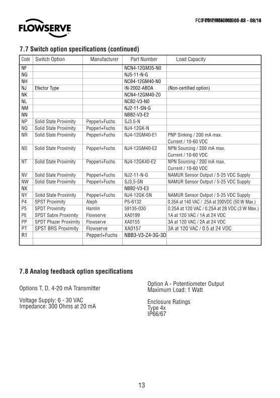
7.7 Switch option specifications (continued)
7.8 Analog feedback option specifications
Options T, D, 4-20 mA Transmitter
Voltage Supply: 6 - 30 VACImpedance: 300 Ohms at 20 mA
NF NCN4-12GM35-N0NG NJ5-11-N-GNH NCB4-12GM40-N0NJ Efector Type IN-2002-ABOA (Non-certified option)NK NCN4-12GM40-Z0NL NCB2-V3-N0NM NJ2-11-SN-GNN NBB2-V3-E2NP Solid State Proximity Pepperl+Fuchs SJ3.5-NNQ Solid State Proximity Pepperl+Fuchs NJ4-12GK-N NR Solid State Proximity Pepperl+Fuchs NJ4-12GM40-E1 PNP Sinking / 200 mA max. Current / 10-60 VDC NS Solid State Proximity Pepperl+Fuchs NJ4-12GM40-E2 NPN Sourcing / 200 mA max. Current / 10-60 VDCNT Solid State Proximity Pepperl+Fuchs NJ4-12GK40-E2 NPN Sourcing / 200 mA max. Current / 10-60 VDCNV Solid State Proximity Pepperl+Fuchs NJ2-11-N-G NAMUR Sensor Output / 5-25 VDC SupplyNW Solid State Proximity Pepperl+Fuchs SJ3,5-SN NAMUR Sensor Output / 5-25 VDC SupplyNX NBB2-V3-E3NY Solid State Proximity Pepperl+Fuchs NJ4-12GK-SN NAMUR Sensor Output / 5-25 VDC SupplyP4 SPST Proximity Aleph PS-6132 0.35A at 140 VAC / .25A at 200VDC (50 W Max.)P5 SPDT Proximity Hamlin 59135-030 0.25A at 120 VAC / 0.25A at 28 VDC (3 W Max.)PE SPDT Sabre Proximity Flowserve XA0199 1A at 120 VAC / 1A at 24 VDC PP SPDT Phazer Proximity Flowserve XA0155 3A at 120 VAC / 2A at 24 VDCPT SPST BRS Proximity Flowserve XA0157 3A at 120 VAC / 0.5 at 24 VDCR1 Pepperl+Fuchs NBB3-V3-Z4-3G-3D
Option A - Potentiometer OutputMaximum Load: 1 Watt
Enclosure RatingsType 4xIP66/67
Code Switch Option Manufacturer Part Number Load Capacity
FCD PMENIM0008-03 A5 - 09/16FCD PMENIM0008-02 - 08/14
14
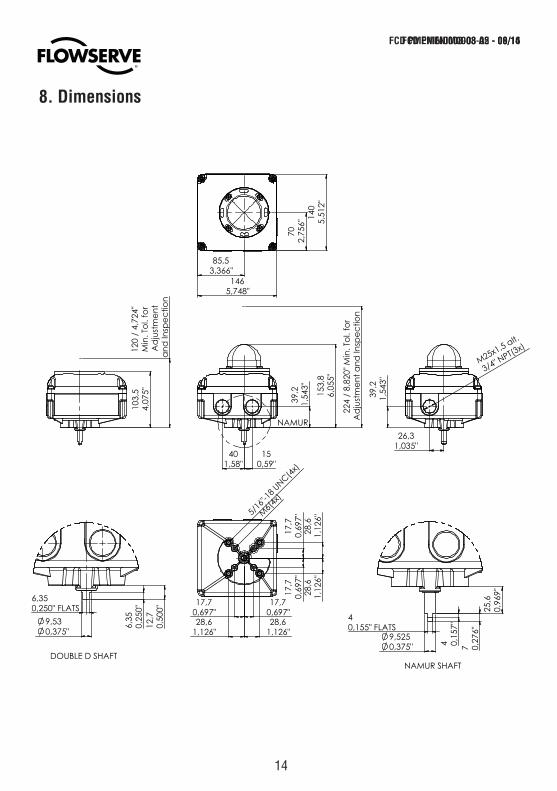
8. Dimensions
TM
FCD PMENIM0008-03 A5 - 09/16FCD PMENIM0008-02 - 08/14
15
Notes
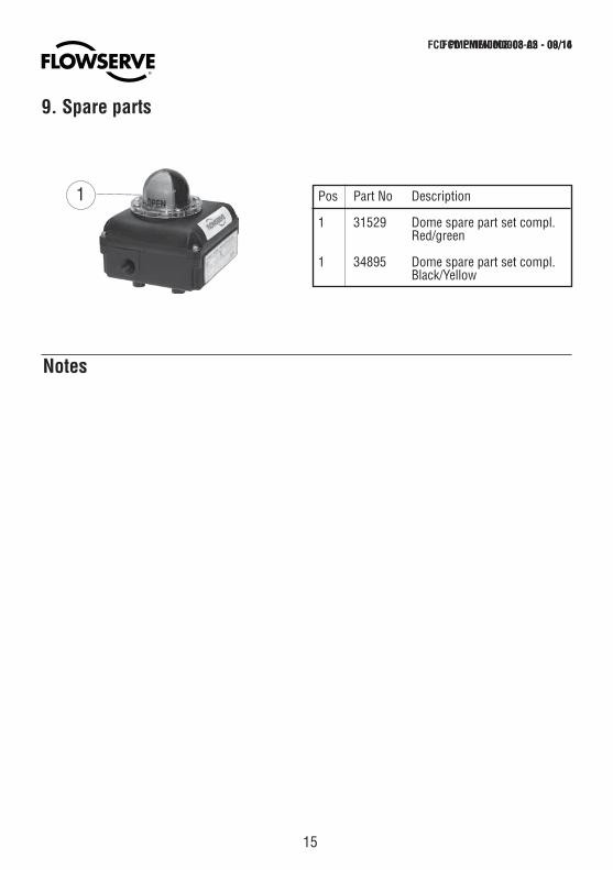
9. Spare parts
Pos Part No Description 1 31529 Dome spare part set compl. Red/green
1 34895 Dome spare part set compl. Black/Yellow
1
FCD PMENIM0008-03 A5 - 09/16FCD PMENIM0008-02 - 08/14
Country NameTown Name, City 00000 CountryTelephone: 0 000 000 0000
Country NameTown Name, City 00000 CountryTelephone: 0 000 000 0000
Country NameTown Name, City 00000 CountryTelephone: 0 000 000 0000
Country NameTown Name, City 00000 CountryTelephone: 0 000 000 0000
Country NameTown Name, City 00000 CountryTelephone: 0 000 000 0000
Country NameTown Name, City 00000 CountryTelephone: 0 000 000 0000
Country NameTown Name, City 00000 CountryTelephone: 0 000 000 0000
Country NameTown Name, City 00000 CountryTelephone: 0 000 000 0000
Country NameTown Name, City 00000 CountryTelephone: 0 000 000 0000
Country NameTown Name, City 00000 CountryTelephone: 0 000 000 0000
Country NameTown Name, City 00000 CountryTelephone: 0 000 000 0000
Country NameTown Name, City 00000 CountryTelephone: 0 000 000 0000
Country NameTown Name, City 00000 CountryTelephone: 0 000 000 0000
To find your local Flowserve representative please usethe Sales Support Locator System found atwww.flowserve.com
Or call toll free: 0 000 000
To find your local Flowserve representative:
Bulletin XX-00-00 (X)
This area can be used for divisional information
Flowserve Corporation has established industry leadership in the design and manufacture of its products. When properly selected, this Flowserveproduct is designed to perform its intended function safely during its useful life. However, the purchaser or user of Flowserve products should be awarethat Flowserve products might be used in numerous applications under a wide variety of industrial service conditions. Although Flowserve can providegeneral guidelines, it cannot provide specific data and warnings for all possible applications. The purchaser/user must therefore assume the ultimateresponsibility for the proper sizing and selection, installation, operation, and maintenance of Flowserve products. The purchaser/user should read andunderstand the (INSERT OFFICIAL USER INSTRUCTION TITLE) instructions included with the product, and train its employees and contractors in thesafe use of Flowserve products in connection with the specific application.
While the information and specifications contained in this literature are believed to be accurate, they are supplied for informative purposes only andshould not be considered certified or as a guarantee of satisfactory results by reliance thereon. Nothing contained herein is to be construed as awarranty or guarantee, express or implied, regarding any matter with respect to this product. Because Flowserve is continually improving and upgradingits product design, the specifications, dimensions and information contained herein are subject to change without notice. Should any question ariseconcerning these provisions, the purchaser/user should contact Flowserve Corporation at any one of its worldwide operations or offices.
For more information about Flowserve Corporation, contact www.flowserve.com or call USA 1-800-225-6989.
To find your local Flowserve representative:
To find your local Flowserve representative please use the Sales Support Locator System found at www.flowserve.com
Flowserve Corporation has established industry leadership in the design and manufacture of its products. When properly selected, this Flowserve product is designed to perform its intended function safely during its useful life. However, the purchaser or user of Flowserve products should be aware that Flowserve products might be used in numerous applications under a wide variety of industrial service conditions. Although Flowserve can provide general guidelines, it cannot provide specific data and warnings for all possible applications. The purchaser/user must therefore assume the ultimate responsibility for the proper sizing and selection, installation, operation, and maintenance of Flowserve products. The purchaser/user should read and understand the (PS/PM Switchbox User Instructions) instructions included with the product, and train its employees and contractors in the safe use of Flowserve products in connection with the specific application.
While the information and specifications contained in this literature are believed to be accurate, they are supplied for informative purposes only and should not be considered certified or as a guarantee of satisfactory results by reliance thereon. Nothing contained herein is to be construed as a warranty or guarantee, express or implied, regarding any matter with respect to this product. Because Flowserve is continually improving and upgrading its product design, the specifications, dimensions and information contained herein are subject to change without notice. Should any question arise concerning these provisions, the purchaser/user should contact Flowserve Corporation at any one of its worldwide operations or offices.
For more information about Flowserve Corporation, contact www.flowserve.com or call USA 1-800-225-6989.
© May 2013, Flowserve Corporation, Irving, Texas
PMV Automation ABKorta Gatan 9SE-171 54 SolnaSWEDEN Tel: +46 (0) 8 555 106 00Fax: +46 (0) 8 555 106 01E-mail: [email protected]
GermanyFlowserve Flow Control GmbHRudolf-Plank Strasse 2D-76275 EttlingenGERMANYTel: +49 (0) 7243 103 0Fax: +49 (0) 7243 103 222E-mail: [email protected]
UKFlowserve Flow ControlBurrell Road, Haywards HeathWest Sussex RH16 1TLPhone: +44(0)1444 314400E-mail: [email protected]
ItalyFlowserve SpaVia Prealpi, 3020032 Cormano (Milano)ITALYsTel: +39 (0) 2 663 251Fax: +39 (0) 2 615 18 63E-mail: [email protected]
USA, MexicoPMV-USA14219 Westfair West DriveHouston, TX 77041, USATel: +1 281 671 9209Fax: +1 281 671 9268E-mail: [email protected]
Asia Pacific HeadquartersFlowserve Pte Ltd.No. 12 Tuas Avenue 20REPUBLIC OF SINGAPORE 638824Tel: +65 (0) 687 98900Fax: +65 (0) 686 24940E-mail: [email protected]
The NetherlandsFlowserve Flow Control BeneluxRechtzaad 174703 RC RoosendaalTHE NETHERLANDSTel: +31 (0) 30 6771946Fax: +27 (0) 30 6772471E-mail: [email protected]
flowserve.com
FCD PMENIM0008-03 A5 - 09/16