Embed Size (px)
Citation preview
USER GUIDE
2
Contents
1. OVERVIEW ................................................................................................................................................ 4
1.1. NodeGrid Manager Features ........................................................................................................... 4
1.2. Supported Console Protocols .......................................................................................................... 5
1.3. Benefits ............................................................................................................................................. 5
1.4. NodeGrid Manager System Requirements ..................................................................................... 5
1.5. Access Options ................................................................................................................................. 6
1.6. Authentication .................................................................................................................................. 7
1.7. Flexible Groups and Users ............................................................................................................... 7
1.8. Managed Devices and Auto-discovery ............................................................................................ 7
1.9. Data Logging, Event Logging, Alerts and Notifications ................................................................... 7
1.10. Security Services and Firewall ......................................................................................................... 8
1.11. MKS, SOL, Virtual Serial, Physical Serial and Power ........................................................................ 8
1.12. IPv4 and IPv6 Support ...................................................................................................................... 8
1.13. SNMP ................................................................................................................................................ 8
2. INSTALLATION & DEPLOYMENT ............................................................................................................... 9
2.1. Creating a Virtual Machine .............................................................................................................. 9
2.2. Installing NodeGrid Manager ......................................................................................................... 10
2.3. Initial NodeGrid Manager Setup .................................................................................................... 11
2.3.1. Adding Servers with Service Processor Support ....................................................................... 12
2.3.2. Adding Devices with SSH or Telnet Support .............................................................................. 13
2.3.3. Adding Virtual Machines ............................................................................................................ 13
2.3.4. Adding Console Servers .............................................................................................................. 14
2.3.5. Auto-Discovery Configuration .................................................................................................... 15
2.4. Configuring Virtual Serial Port (vSPC) on VM SERVERS ................................................................ 16
3. ACCESS & TRACKING .............................................................................................................................. 18
3.1. Web, SSH or Telnet ......................................................................................................................... 18
3.1.1. Using Telnet to Connect to a Managed Device ......................................................................... 19
3.1.2. Using SSH to Connect to a Managed Device ............................................................................. 19
3.2. Tracking ........................................................................................................................................... 20
4. CONFIGURATION - SYSTEM ................................................................................................................... 21
4.1. Preferences ..................................................................................................................................... 21
4.2. Date and Time ................................................................................................................................ 22
4.3. License ............................................................................................................................................ 22
TABLE OF CONTENTS

3
4.4. Toolkit.............................................................................................................................................. 22
4.5. Logging ............................................................................................................................................ 22
4.6. Custom Fields ................................................................................................................................. 22
5. CONFIGURATION - NETWORK ............................................................................................................... 23
5.1. Settings ........................................................................................................................................... 23
5.2. Interfaces ........................................................................................................................................ 23
5.3. Static Routes ................................................................................................................................... 24
5.4. Hosts ............................................................................................................................................... 24
5.5. SNMP .............................................................................................................................................. 24
5.6. DHCP Server ................................................................................................................................... 24
6. CONFIGURATION - MANAGED DEVICES ................................................................................................ 26
6.1. Devices ............................................................................................................................................ 26
6.2. Templates ........................................................................................................................................ 28
6.3. Target Types .................................................................................................................................... 28
6.4. Auto-discovery ................................................................................................................................ 28
6.5. VM Manager ................................................................................................................................... 30
7. CONFIGURATION - SECURITY ................................................................................................................. 31
7.1. Local Accounts ................................................................................................................................ 31
7.2. Authorization .................................................................................................................................. 32
7.3. Authentication ................................................................................................................................ 34
7.3.1. Setting authentication type ....................................................................................................... 34
7.4. Firewall ............................................................................................................................................ 35
7.5. Services ........................................................................................................................................... 36
8. CONFIGURATION - AUDITING ................................................................................................................ 38
8.1. Event Destination ........................................................................................................................... 38
8.2. Logging Destination ........................................................................................................................ 39
9. TECHNICAL SUPPORT ............................................................................................................................. 40
4
NodeGrid Manager is a vendor neutral software-defined infrastructure virtual appliance
for access and control across of all devices in data centers and test lab environments.
NodeGrid Manager’s core engine utilizes a technology stack that allows for policy based
automated discovery and configuration of your asset consoles to minimize configuration
and maintenance and utilizes a complete interface abstraction layer that implements the
many protocols and methods required to access and control your consoles from multiple
vendors.
NodeGrid's flexible console interface provides a complete Web interface and CLI (for
scripting) enabling complete customization and integration of your own console portals
and applications.
1.1. NodeGrid Manager Features
• Secure access and control of virtual and physical IT devices
• DeviceURL™ bookmarks
• NodeIQ™ elastic asset search
• Cloud Clustering™ with horizontal and vertical scaling
• FireTrail™ secure tunnel-through-firewall access
• Shared Access with Console Data Logging
• Service Processor Logging of Events and Sensors
• Event notification and Alarms
• Power Management
• Auto-discovery of virtual and physical devices
• Policy-based Authentication and Authorization via AD/LDAP
• Web and CLI single interface
1. OVERVIEW
5
1.2. Supported Console Protocols
• Service processors (iLO, DRAC, IPMI, CIMC/UCS, IMM, ILOM)
• VMWare™ (Serial Console, MKS, vMotion™ migration tracking), KVM VMs (Serial
Console)
• Legacy consoles (TELNET, SSH)
1.3. Benefits
• Single screen access and control experience of physical and virtual assets
• Quick and easy infrastructure deployment
• Vendor neutral support for all console protocols
• No need to maintain multiple vendors' admin tools
• Save time with policy-based discovery and management
• Keep firewalls secure
• All in one. Installs from bootable ISO, no other software required.
• Simplifies day-zero deployments
1.4. NodeGrid Manager System Requirements
NodeGrid Manager runs as a complete system solution on a Linux 32-bit host virtual
machine. The software is provided as a bootable ISO file. While NodeGrid Manager can
be installed in different virtualization environments, this installation document will
describe how to install it on a VMware ESXiTM server (minimum version ESXi 4.1). A client
workstation running VMware infrastructure client software (vSphereTM) is also required to
support the installation. The following are the minimum requirements for the virtual
machine in order to host NodeGrid Manager System:
• 2 GB hard drive space;
• 4 GB memory;
• Network adaptor;
• Access to NodeGrid Manager ISO file.
For instructions on how to install NodeGrid Manager, refer to chapter 2.
6
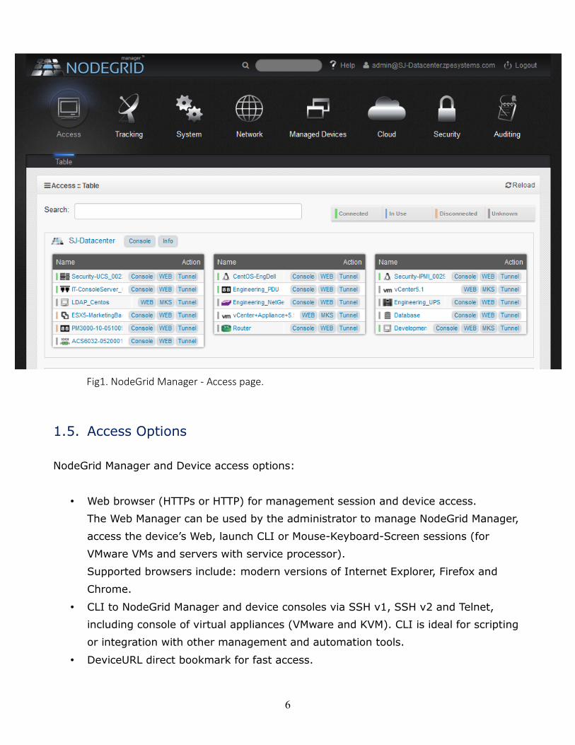
Fig1. NodeGrid Manager - Access page.
1.5. Access Options
NodeGrid Manager and Device access options:
• Web browser (HTTPs or HTTP) for management session and device access.
The Web Manager can be used by the administrator to manage NodeGrid Manager,
access the device’s Web, launch CLI or Mouse-Keyboard-Screen sessions (for
VMware VMs and servers with service processor).
Supported browsers include: modern versions of Internet Explorer, Firefox and
Chrome.
• CLI to NodeGrid Manager and device consoles via SSH v1, SSH v2 and Telnet,
including console of virtual appliances (VMware and KVM). CLI is ideal for scripting
or integration with other management and automation tools.
• DeviceURL direct bookmark for fast access.
7
1.6. Authentication
NodeGrid Manager supports local authentication and remote authentication systems
including: Kerberos, LDAP, Radius, and Tacacs+. Once a configuration method is selected,
it will be used for authentication of any access to the system via Web, CLI and console of
the virtual machine running NodeGrid Manager.
1.7. Flexible Groups and Users
User accounts can be created locally on NodeGrid Manager or remotely on authentication
servers if remote authentication is selected. The admin user can add new user accounts
and create authorization groups in order to provide access rights to managed devices and
access profiles per user.
1.8. Managed Devices and Auto-discovery
The admin user can add managed devices following a variety of predefined profile types.
Each managed device requires a license from the license pool in order to be accessible.
NodeGrid Manager also supports device discovery. This feature allows newly discovered
devices to be cloned from existing devices matching their profile to build dynamic access
groups.
1.9. Data Logging, Event Logging, Alerts and Notifications
NodeGrid Manager retains archives of data logging and event logging of managed devices
in local files or remotely via NFS. Logs can be used for inspection, compliance and
auditing purposes. Real-time alerts can be generated from data and event feeds
generated by the devices based on configurable regular expression string. Notifications
via Syslog, Email or SNMP trap can be used to alert administrators about problems on
managed devices or on NodeGrid Manager.
8
1.10. Security Services and Firewall
The user admin can enable and disable services, configure active ports, define firewall
rules, set session timeout per groups, define expiration dates for local user accounts and
require password renewal at login time. The admin can also create and configure chains
to control packet filtering. NodeGrid Manager ships with pre-defined built-in chains for
ease of use.
1.11. MKS, SOL, Virtual Serial, Physical Serial and Power
NodeGrid Manager offers a vendor neutral normalized console interface access for
managed devices via:
virtual serial console (for virtual appliances running on VMwareTM or KVM),
multi-vendor service processor SOL (serial over lan) console,
physical serial console port via multi-vendor console server appliances,
power via service processor, virtual machines or network PDUs.
It also supports MKS (Mouse-Keyboard-Screen) for graphical UI of VMwareTM virtual
machines.
1.12. IPv4 and IPv6 Support
NodeGrid Manager supports single IPv4 stack or dual IPv4 and IPv6 stack (note: NFS
supports IPv4 only). The following services are supported for IPv6:
• HTTP / HTTPs access; SSH and Telnet access; Remote Authentication: Kerberos,
Tacacs+, Radius and LDAP; SNMP; Linux Kernel; Firewall (IP tables); DHCP and
Syslog server.
1.13. SNMP
SNMP v1, v2 and v3 are supported for the Enterprise MIB.
9
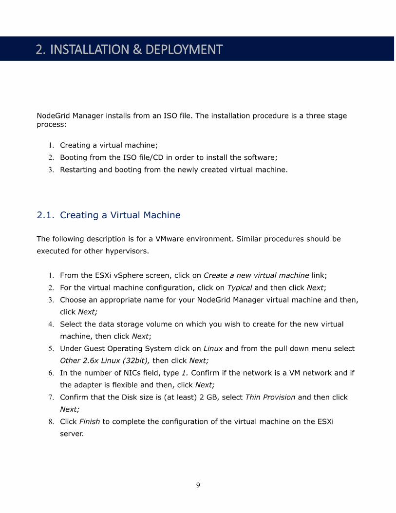
NodeGrid Manager installs from an ISO file. The installation procedure is a three stage process:
1. Creating a virtual machine;
2. Booting from the ISO file/CD in order to install the software;
3. Restarting and booting from the newly created virtual machine.
2.1. Creating a Virtual Machine
The following description is for a VMware environment. Similar procedures should be
executed for other hypervisors.
1. From the ESXi vSphere screen, click on Create a new virtual machine link;
2. For the virtual machine configuration, click on Typical and then click Next;
3. Choose an appropriate name for your NodeGrid Manager virtual machine and then,
click Next;
4. Select the data storage volume on which you wish to create for the new virtual
machine, then click Next;
5. Under Guest Operating System click on Linux and from the pull down menu select
Other 2.6x Linux (32bit), then click Next;
6. In the number of NICs field, type 1. Confirm if the network is a VM network and if
the adapter is flexible and then, click Next;
7. Confirm that the Disk size is (at least) 2 GB, select Thin Provision and then click
Next;
8. Click Finish to complete the configuration of the virtual machine on the ESXi
server.
2. INSTALLATION & DEPLOYMENT
10
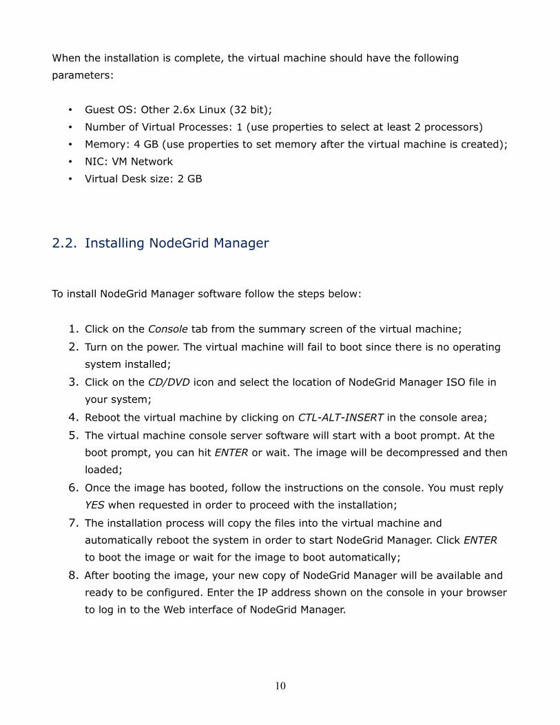
When the installation is complete, the virtual machine should have the following
parameters:
• Guest OS: Other 2.6x Linux (32 bit);
• Number of Virtual Processes: 1 (use properties to select at least 2 processors)
• Memory: 4 GB (use properties to set memory after the virtual machine is created);
• NIC: VM Network
• Virtual Desk size: 2 GB
2.2. Installing NodeGrid Manager
To install NodeGrid Manager software follow the steps below:
1. Click on the Console tab from the summary screen of the virtual machine;
2. Turn on the power. The virtual machine will fail to boot since there is no operating
system installed;
3. Click on the CD/DVD icon and select the location of NodeGrid Manager ISO file in
your system;
4. Reboot the virtual machine by clicking on CTL-ALT-INSERT in the console area;
5. The virtual machine console server software will start with a boot prompt. At the
boot prompt, you can hit ENTER or wait. The image will be decompressed and then
loaded;
6. Once the image has booted, follow the instructions on the console. You must reply
YES when requested in order to proceed with the installation;
7. The installation process will copy the files into the virtual machine and
automatically reboot the system in order to start NodeGrid Manager. Click ENTER
to boot the image or wait for the image to boot automatically;
8. After booting the image, your new copy of NodeGrid Manager will be available and
ready to be configured. Enter the IP address shown on the console in your browser
to log in to the Web interface of NodeGrid Manager.
11
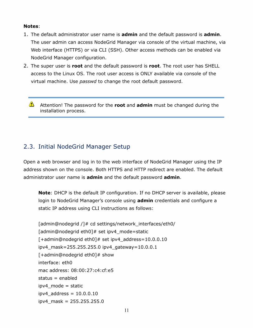
Notes:
1. The default administrator user name is admin and the default password is admin.
The user admin can access NodeGrid Manager via console of the virtual machine, via
Web interface (HTTPS) or via CLI (SSH). Other access methods can be enabled via
NodeGrid Manager configuration.
2. The super user is root and the default password is root. The root user has SHELL
access to the Linux OS. The root user access is ONLY available via console of the
virtual machine. Use passwd to change the root default password.
2.3. Initial NodeGrid Manager Setup
Open a web browser and log in to the web interface of NodeGrid Manager using the IP
address shown on the console. Both HTTPS and HTTP redirect are enabled. The default
administrator user name is admin and the default password admin.
Note: DHCP is the default IP configuration. If no DHCP server is available, please
login to NodeGrid Manager’s console using admin credentials and configure a
static IP address using CLI instructions as follows:
[admin@nodegrid /]# cd settings/network_interfaces/eth0/
[admin@nodegrid eth0]# set ipv4_mode=static
[+admin@nodegrid eth0]# set ipv4_address=10.0.0.10
ipv4_mask=255.255.255.0 ipv4_gateway=10.0.0.1
[+admin@nodegrid eth0]# show
interface: eth0
mac address: 08:00:27:c4:cf:e5
status = enabled
ipv4_mode = static
ipv4_address = 10.0.0.10
ipv4_mask = 255.255.255.0
Attention! The password for the root and admin must be changed during the
installation process.
12
ipv4_gateway = 10.0.0.1
ipv6_mode = no_ipv6_address
[+admin@nodegrid eth0]# commit
[admin@nodegrid eth0]# exit
Open a web browser using the static IP address and login as admin user.
CLI hints:
At any point in CLI you can press the Tab key and the interface will show the
available options.
Type ‘show’ to display the parameters available for the present path (i.e. folder).
Type ‘ls’ to display the paths available following the present path.
Once NodeGrid Manager has an IP address, please continue the configuration via web
browser.
1. During first time login, the admin user will be required to change the default
password. Provide the information requested on screen and click on Change
Password button;
2. On the main page, select System :: License, click the Add button, enter the license
information and click on Save button;
2.3.1. Adding Servers with Service Processor Support
3. Select Managed Devices :: Devices, click the Add button to add a device in the
system. For the purpose of this example, provide the following information:
On the Name field, type the name of the server you want to add. This device
should be a server that supports Service Processor. Enter the IP address of the
service processor on this server. Make sure the IP address is reachable by
NodeGrid Manager. On the Type field, select type that matches the service
processor profile in use. Type username and password of the administrator account
on the service processor and then, click the Save button.
13
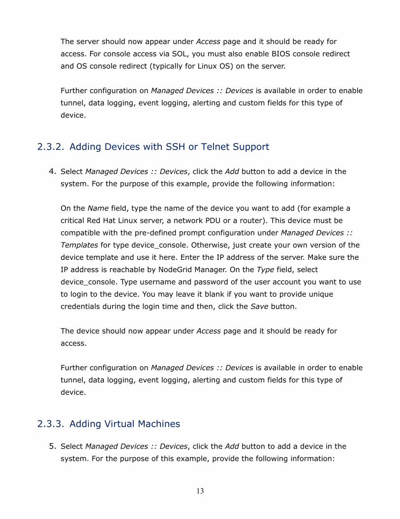
The server should now appear under Access page and it should be ready for
access. For console access via SOL, you must also enable BIOS console redirect
and OS console redirect (typically for Linux OS) on the server.
Further configuration on Managed Devices :: Devices is available in order to enable
tunnel, data logging, event logging, alerting and custom fields for this type of
device.
2.3.2. Adding Devices with SSH or Telnet Support
4. Select Managed Devices :: Devices, click the Add button to add a device in the
system. For the purpose of this example, provide the following information:
On the Name field, type the name of the device you want to add (for example a
critical Red Hat Linux server, a network PDU or a router). This device must be
compatible with the pre-defined prompt configuration under Managed Devices ::
Templates for type device_console. Otherwise, just create your own version of the
device template and use it here. Enter the IP address of the server. Make sure the
IP address is reachable by NodeGrid Manager. On the Type field, select
device_console. Type username and password of the user account you want to use
to login to the device. You may leave it blank if you want to provide unique
credentials during the login time and then, click the Save button.
The device should now appear under Access page and it should be ready for
access.
Further configuration on Managed Devices :: Devices is available in order to enable
tunnel, data logging, event logging, alerting and custom fields for this type of
device.
2.3.3. Adding Virtual Machines
5. Select Managed Devices :: Devices, click the Add button to add a device in the
system. For the purpose of this example, provide the following information:
14
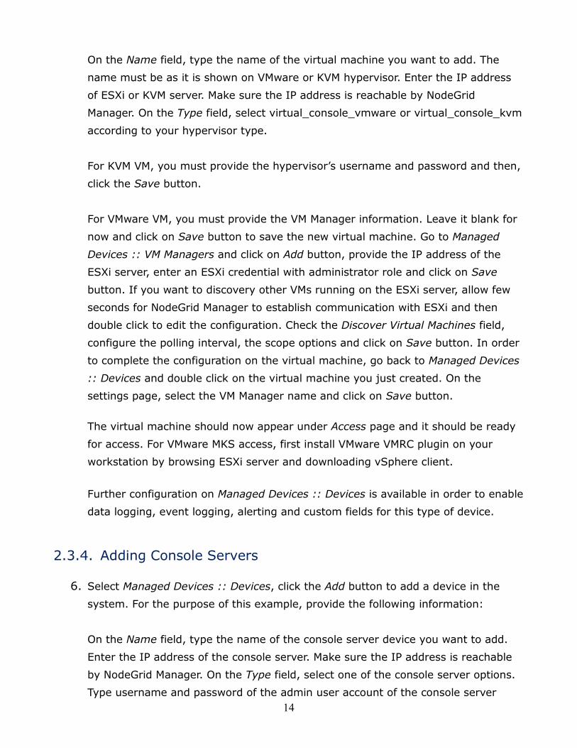
On the Name field, type the name of the virtual machine you want to add. The
name must be as it is shown on VMware or KVM hypervisor. Enter the IP address
of ESXi or KVM server. Make sure the IP address is reachable by NodeGrid
Manager. On the Type field, select virtual_console_vmware or virtual_console_kvm
according to your hypervisor type.
For KVM VM, you must provide the hypervisor’s username and password and then,
click the Save button.
For VMware VM, you must provide the VM Manager information. Leave it blank for
now and click on Save button to save the new virtual machine. Go to Managed
Devices :: VM Managers and click on Add button, provide the IP address of the
ESXi server, enter an ESXi credential with administrator role and click on Save
button. If you want to discovery other VMs running on the ESXi server, allow few
seconds for NodeGrid Manager to establish communication with ESXi and then
double click to edit the configuration. Check the Discover Virtual Machines field,
configure the polling interval, the scope options and click on Save button. In order
to complete the configuration on the virtual machine, go back to Managed Devices
:: Devices and double click on the virtual machine you just created. On the
settings page, select the VM Manager name and click on Save button.
The virtual machine should now appear under Access page and it should be ready
for access. For VMware MKS access, first install VMware VMRC plugin on your
workstation by browsing ESXi server and downloading vSphere client.
Further configuration on Managed Devices :: Devices is available in order to enable
data logging, event logging, alerting and custom fields for this type of device.
2.3.4. Adding Console Servers
6. Select Managed Devices :: Devices, click the Add button to add a device in the
system. For the purpose of this example, provide the following information:
On the Name field, type the name of the console server device you want to add.
Enter the IP address of the console server. Make sure the IP address is reachable
by NodeGrid Manager. On the Type field, select one of the console server options.
Type username and password of the admin user account of the console server
15
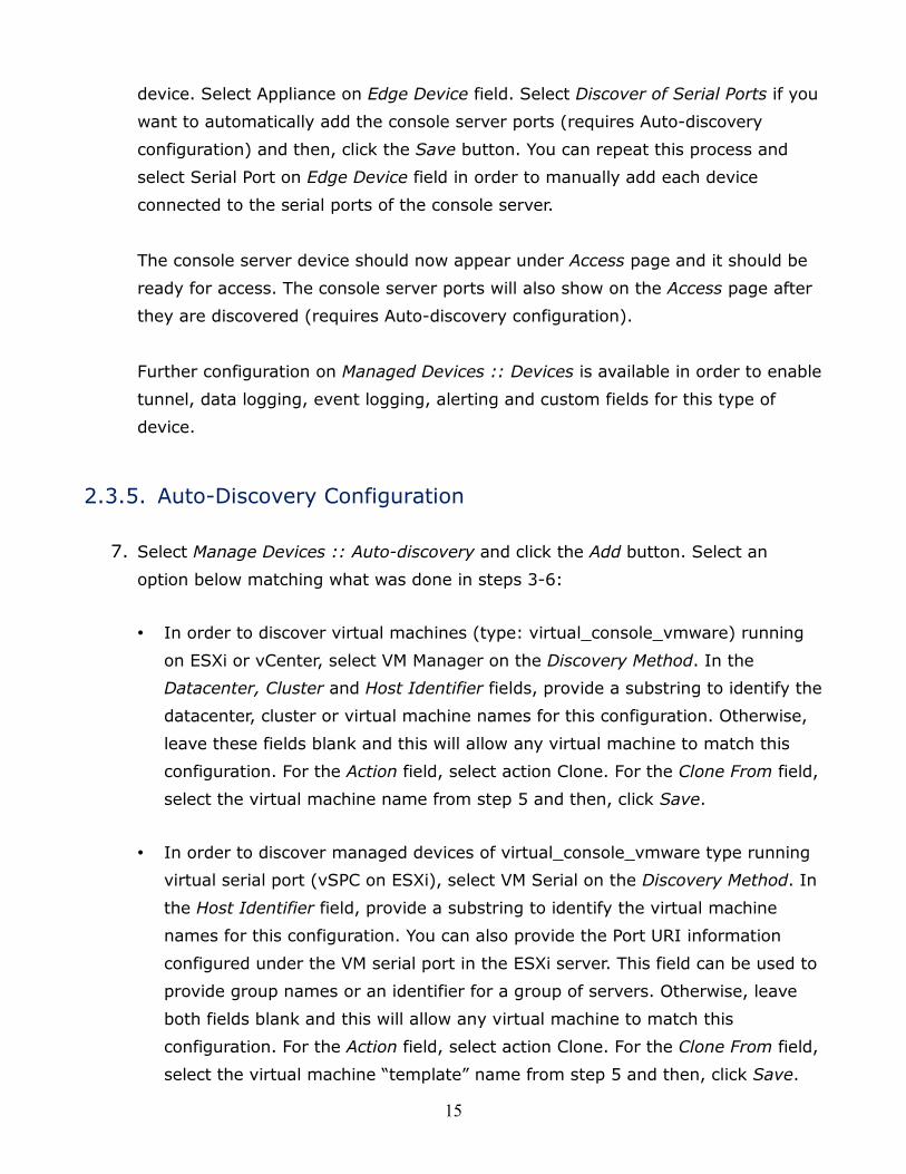
device. Select Appliance on Edge Device field. Select Discover of Serial Ports if you
want to automatically add the console server ports (requires Auto-discovery
configuration) and then, click the Save button. You can repeat this process and
select Serial Port on Edge Device field in order to manually add each device
connected to the serial ports of the console server.
The console server device should now appear under Access page and it should be
ready for access. The console server ports will also show on the Access page after
they are discovered (requires Auto-discovery configuration).
Further configuration on Managed Devices :: Devices is available in order to enable
tunnel, data logging, event logging, alerting and custom fields for this type of
device.
2.3.5. Auto-Discovery Configuration
7. Select Manage Devices :: Auto-discovery and click the Add button. Select an
option below matching what was done in steps 3-6:
• In order to discover virtual machines (type: virtual_console_vmware) running
on ESXi or vCenter, select VM Manager on the Discovery Method. In the
Datacenter, Cluster and Host Identifier fields, provide a substring to identify the
datacenter, cluster or virtual machine names for this configuration. Otherwise,
leave these fields blank and this will allow any virtual machine to match this
configuration. For the Action field, select action Clone. For the Clone From field,
select the virtual machine name from step 5 and then, click Save.
• In order to discover managed devices of virtual_console_vmware type running
virtual serial port (vSPC on ESXi), select VM Serial on the Discovery Method. In
the Host Identifier field, provide a substring to identify the virtual machine
names for this configuration. You can also provide the Port URI information
configured under the VM serial port in the ESXi server. This field can be used to
provide group names or an identifier for a group of servers. Otherwise, leave
both fields blank and this will allow any virtual machine to match this
configuration. For the Action field, select action Clone. For the Clone From field,
select the virtual machine “template” name from step 5 and then, click Save.
16
• In order to discover managed devices of service processor type, select DHCP
under Discovery Method. This enables NodeGrid Manager to evaluate the
discovery rules for any server with a service processor that requests DHCP.
Please note that this option requires DHCP Server enable under Network ::
DHCP Server. For Mac Address provide the three first octets or full MAC Address
of the devices that you want to discover. In the Host Identifier field, provide a
substring to identify the server names for this configuration. Fields left blank
will not be used during the discovery to match this configuration. In the Action
field, select action Clone. For the Clone From field, select the server name from
step 3 and then, click Save.
• In order to discover console servers and ports (type: console_server_xxxxx),
select Console Server on the Discovery Method. In the Port List field, provide a
list of individual ports separated by commas and/or port range separated by
dash to be discovered. In the Host Identifier field, provide a substring to
identify the console server names or console server port names for this
configuration. Otherwise, leave these fields blank and this will allow any console
server or port to match this configuration. For the Action field, select action
Clone. For the Clone From field, select the console server name from step 6 and
then, click Save.
NodeGrid Manager is now configured with basic information and ready to discover servers
with service processor and virtual machines and to accept users and connections to
managed devices.
2.4. Configuring Virtual Serial Port (vSPC) on VM SERVERS
In order to redirect the VMware virtual machine vSPC data to NodeGrid Manager, the
virtual machine serial port needs to be configured as described below:
1. Go to ESXi configuration (vSphereTM). Select the virtual machine you want to
connect and click the Edit Virtual Machine Settings link;
2. Click Add. The virtual machine must be turned off;
3. Click Serial Manager Device, then click on Next in the pop-up window;
4. Click Connect Via Network, then click Next;
17
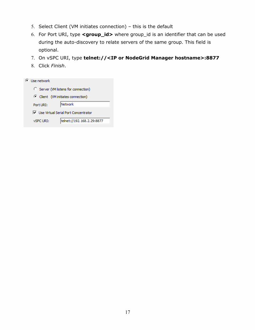
5. Select Client (VM initiates connection) – this is the default
6. For Port URI, type <group_id> where group_id is an identifier that can be used
during the auto-discovery to relate servers of the same group. This field is
optional.
7. On vSPC URI, type telnet://<IP or NodeGrid Manager hostname>:8877
8. Click Finish.
18
3.1. Web, SSH or Telnet
You can access NodeGrid Manager through the Web, SSH and Telnet. If you want to log
into the Web interface, open a Web browser and enter the NodeGrid Manager IP address
in the address field. Both HTTPs and HTTP redirect to HTTPs are enabled by default. If
you want to login to the CLI, open an SSH or Telnet session using the NodeGrid IP
address. Please note that only SSH protocol is enable by default.
The default administrator user is: admin, password: admin
As the admin user connected to a Web session, you can view all the devices that are
enrolled under NodeGrid Manager by clicking on Access. If authorization enforcement is
enabled, then the user will see only the managed devices configured under the groups
he/she belongs to.
In order to view the devices and connect to a managed device via Web session, follow
the steps below:
1. Select Access on the top navigation. A list of names or aliases for all configured
and installed devices which the user is authorized to access, will be displayed on
the content area;
2. In the Action Column, select Console and a Java applet viewer will start. On the
top of the viewer window you will see the name of the managed device you are
connected to.
A Telnet or SSH client can be used by an authorized user to establish a connection
straight to the console of a managed device if:
• The Telnet or SSH protocol is enabled in the NodeGrid Manager’s security settings;
• A user name and password is provided upon connection. Make sure to create local
users or enable remote authentication for enterprise users.
3. ACCESS & TRACKING
19
3.1.1. Using Telnet to Connect to a Managed Device
For this procedure, you need the username configured to access the managed device, the
managed device name (for example, Development_CentOS), and the hostname or IP
address of NodeGrid Manager.
To use a Telnet client, enter the information in the dialog boxes of the client.
-or-
To use Telnet in a shell, enter the following command:
# telnet [hostname | IP_address]
login: username:[ device_name]
Example: $ telnet 192.168.2.164 Trying 192.168.2.164... Connected to 192.168.2.164. Escape character is '^]'. NodeGrid 2.0.0 Aug 12 2014 - 06:09:31 NewYork-DC login: admin:Development_CentOS Password: [Enter `^Ec?' for help] [Enter `^Ec.' to disconnect] CentOS release 6.4 (Final) Kernel 2.6.32-358.el6.x86_64 on an x86_64 CentOS-srv.zpesystems.com login:
3.1.2. Using SSH to Connect to a Managed Device
For this procedure, you need the username configured to access the managed device, the
managed device name (for example, Server-Eng), and the hostname of the NodeGrid
Manager server or its IP address.
To use an SSH client, enter the information in the dialog boxes of the client.
-or-
To use SSH in a shell, enter the following command:
ssh -l username:device_name [hostname | IP_address]
20
Example: $ ssh admin:[email protected] Password: [Enter `^Ec?' for help] [Enter `^Ec.' to disconnect] CentOS release 6.4 (Final) Kernel 2.6.32-358.el6.x86_64 on an x86_64 CentOS-srv.zpesystems.com login:
If you have to close an SSH/Telnet session (Java Applet always uses SSH), just type exit
from the CLI. If you have connected directly to a managed device, use ^EC. hotkey to go
back to CLI mode.
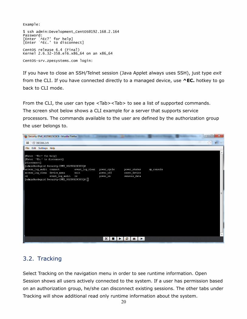
From the CLI, the user can type <Tab><Tab> to see a list of supported commands.
The screen shot below shows a CLI example for a server that supports service
processors. The commands available to the user are defined by the authorization group
the user belongs to.
3.2. Tracking
Select Tracking on the navigation menu in order to see runtime information. Open
Session shows all users actively connected to the system. If a user has permission based
on an authorization group, he/she can disconnect existing sessions. The other tabs under
Tracking will show additional read only runtime information about the system.
21
The system menu options are as following:
4.1. Preferences
This page allows the user to configure system’s parameters. The following fields
are relevant for this page:
• Address Location is a free format field for the address location of NodeGrid
Manager.
• Online help allows the user to define an alternate location where the user manual
can be posted. When the user clicks on the Help button on the top right corner of
the Web interface, a new Web page opens up and the file defined on this URL
location is shown. The Web server’s root directory default location is within
NodeGrid Manager. However the administrator can download the file from
NodeGrid Manager (or a new update from the ZPE Systems Website) and post the
manual in any other location of the network that is reachable by NodeGrid
Manager.
• Login Banner allows the system to show a common message during the login
process. The message will be shown on Telnet, SSH, HTTP, HTTPs and Console.
This is typically used to show warning messages before the user logs in on the
system. The admin user can edit and customize the default message.
• Session Timeout allows the admin user to configure the number of minutes before
open sessions are timed out. Configuration changes on this field will be effective
for new sessions only. Existing sessions will continue following their session
timeout value specified during their login time. A zero in this field allows new
sessions to never expire.
4. CONFIGURATION - SYSTEM
22
4.2. Date and Time
The date and time can be retrieved from a Network Time Protocol (NTP) server or
be set manually. NTP is the default configuration for this option and it will try to retrieve
the date and time from any server in the NTP pool. In manual configuration mode,
NodeGrid Manager will use its own clock to provide date and time information. The user
must refresh this page to see current system time.
4.3. License
Select this option to view license information for NodeGrid Manager. Enrolled
licenses will show on this table along with detailed information about the number of
managed licenses and any other relevant information. Multiple licenses can be added on
the system. For licenses of the same type, the total number of allowed managed devices
will be the sum of all licenses up to upper limit supported by the system (currently 1,000
nodes). Excess devices beyond this limit will not be supported. The top right corner of
this content page shows a summary of the licenses installed, in use and available. Click
on Add if you want to add a license and then, in the license field, enter the number of the
license you are adding. If you want to delete a license, click on its respective box and
then click on Delete.
4.4. Toolkit
Use this option to reboot, shutdown, save settings (to backup settings), apply
settings (to restore settings), apply system certificates and restore to factory default
settings (erase and recover original installation settings).
4.5. Logging
Use this option to enable data logging collection of CLI sessions. If this selection is
enabled, all data exchange during a CLI session will be logged for auditing and
inspection. The admin user can inspect and clear data logs via the CLI command.
4.6. Custom Fields
Use this selection to add searchable custom fields and value.
23
The network menu options are as follows:
5.1. Settings
Use this selection to configure the hostname for NodeGrid Manager, static DNS
information and to enable an IPv6 network stack.
5.2. Interfaces
This page will list all the available Ethernet interfaces created for the virtual
machine hosting NodeGrid Manager. A total of 4 Ethernet interfaces can be enabled on
the system. The Ethernets must be created by the hypervisor management system.
Drilldown to the interface to enable it and configure additional IPv4 and IPv6 parameters.
In order to support IPv6, IPv6 support needs to be enabled under Network :: Settings.
IPv4 method options below:
• DHCP if you want to have the IPv4 address set by the DHCP server;
• IPv4 address unconfigured to disable IPv4.
• Static, if you want to enter the subnet mask and the IPv4 IP address manually.
IPv6 method options below:
• Static to enter the prefix length and the IPv6 IP address manually;
• DHCPv6 if you want to have the IPv6 IP address set by the DHCP server;
• Stateless if the link is restricted to the local IP address;
• Unconfigured IPv6 address to disable IPv6.
5. CONFIGURATION - NETWORK
24
5.3. Static Routes
This page allows the user to create IPv4 and IPv6 static routes. Any existing static
routes will be listed in the table. The user can create default, IP or Network routes.
Static Routes (IPv4 and IPv6)
Adding Static Routes, select:
1. Click on Add;
2. Default to configure the default route;
3. In the Gateway field, enter the Gateway IP address;
4. In the Metric Field, enter the number of hops to your destination, then click
the Save button.
Note: Go to Tracking :: Routing Table page to see the current running routing table.
5.4. Hosts
This page allows sysadmins to add managed hosts by adding an IP address, host
and alias. Any existing hosts will be listed in the table.
5.5. SNMP
This page lists any existing SNMP configuration and it allows the user to create
new ones. Use System button to enter system’s contact and location. Use Add button to
add v1, v2 community name or v3 user name, along with the OID information and
desired permissions. Select the v1, v2 option and provide the source (subnet address) or
v3 option and then select the Authentication Type (MD5 or SHA) and enter the
authentication passphrase Level (NoAuthNoPriv, AuthNoPriv, AuthPriv).
Note: Only enterprise information is currently available under SNMP.
5.6. DHCP Server
NodeGrid Manager may be configured to serve IP addresses for the managed
devices in the management network. This is typically the case of servers running service
processors. Since each service processor requires an IP address, it is convenient to have
the management network requesting DHCP from NodeGrid Manager. This page will list

25
any existing DHCP configuration. Click on Add or drill down to existing entries to
configure a DHCP server. In order to add new entries, provide the subnet and netmask of
the interface served by DHCP. Optionally you can provide domain, DNS and router IP
address. Network ranges and hosts can be added to the configuration as well.
26
The Managed Devices menu options are as follows:
6.1. Devices
This page list all managed devices enrolled in the NodeGrid Manager system. The
top right corner of the table shows the total licenses in the system, total in use and total
available. Each managed device added in the system uses one license from the pool. If
licenses expire or are deleted from the system, the devices exceeding the total licenses
will have their status changed to “unlicensed”. While their information will be retained in
the system, the unlicensed devices will not show up in the access page preventing the
user from connecting to them. Only licensed devices are listed on the access page and
are available for access and management.
For adding or editing devices, the following fields are relevant:
• Name is the unique name of the managed device. It should be the hostname of
the server, hostname of the console server or the virtual machine name in the ESXi
or KVM hypervisor. The managed device name will be used for connecting via Web
or CLI (SSH or Telnet).
• IP Address is the managed device’s IP address. For virtual machines, enter the IP
address of the hypervisor.
• Address Location is a free format field for the address location of the device
• WEB URL is the managed device URL, if it is available. %IP is a macro that will be
replaced by the actual managed device’s IP address.
• Type – select the appropriate type from the pull-down selection.
The following types ilo (HP), imm (IBM), drac (DELL), ipmi_1.5 and ipmi_2.0
(Super Micro), ilom (Oracle), cimc_ucs (Cisco) are for service processors;
The device_console type is for generic devices that respond to SSH or Telnet
protocols
The vm_console_vmware type is for VMwareTM virtual machines using MKS-Mouse
Keyboard and Screen or vSPC for virtual serial port.
6. CONFIGURATION - MANAGED DEVICES
27
The vm_console_kvm type is for KVM virtual machines using virtual serial port.
The console_server_xxx types are for Serial Consoles from Avocent/Cyclades and
OpenGear.
• Username and Password for the privileged user on the managed device. This
account will be used for logging into the device in order to collect data logging and
event logging. Typically this is the admin user of the service processor or console
server. Note: vm_console_vmware type does not require username and password.
• Mode settings allow to control the state of the device.
Enabled – the device is visible on Access page. The Console connection
between NodeGrid Manager and the device will remain established to allow
collecting data logs sent by the device’s console, regardless if the session is in
use.
On-demand – the device is visible on Access page. The Console connection
between NodeGrid Manager and the device will be established dynamically
when there is a user using the session. The connection will be disconnected
when the last user terminates the session with the device.
Disabled – the device is not visible on Access page. The Console connection
between NodeGrid Manager and the device is not established. Use this mode if
you want to disallow temporarily access to device (for example when device is
maintenance mode).
Discovered – the device is not visible on Access page. The Console
connection between NodeGrid Manager and the device is not established. This
device was auto-discovered and it is currently parked on this state for review
by admin.
• End Device settings for console_server_xxx type. This allows NodeGrid Manager to
identify if the managed device is for the appliance itself or for one of the serial
ports on the console server. Discovery allows the system to fetch information
about new serial ports on the console server or updates on existing serial ports.
• Enable Send Break allows admins to customize the Break Sequence to be used by
this managed device.
• Multisession allows multiple users to log to the same managed device
simultaneously. For auditing and tracking purposes, only one user will have control
of the session at a time. The others will be in read-only mode.
• Data Log and Event Log selection will configure the system to collect data log (not
available for MKS sessions) and event log from the device (for service processor
device type only). Event Log Frequency and Event Log Unit will set the frequency
28
to collect the event log from the service processor. Both alerts and events support
Alert Strings and Event Strings, which are regular expression pattern string that
are evaluated against the data source stream as the data is collected. Events are
generated for each match.
6.2. Templates
Templates hold specific information about the CLI prompt characteristics from
different targets. NodeGrid Manager provides several pre-configured templates that can
be cloned and modify in order to grow your portfolio of templates. Select a single
template and use the Clone button to make a copy of it. You can edit the template in
order to make further changes. Pre-defined templates can be modified, but cannot be
deleted.
6.3. Target Types
Target Types hold specific information about the family type (required for the
device driver identification), protocol to be used for communication, and the template
associated to different targets. NodeGrid Manager provides several pre-configured target
types that can be cloned and modify in order to grow even more your portfolio. Select a
single target type and use the Clone button to make a copy of it. You can edit the target
type in order to make further changes. Pre-defined target types can be modified, but
cannot be deleted.
6.4. Auto-discovery
This feature allows newly discovered devices to be cloned from existing devices
matching their profile and build dynamic access groups. For best results with this feature,
make sure the device to be used as reference in the cloning process is correctly
configured. Verify that username, password and IP address are correct by accessing the
device. Verify that the data logging and event logging settings are correct by auditing the
log files. Verify that events are being detected based on data logging and event logging
by simulating events and checking if any notification was created. Verify that the device
is in the desirable authorization group with correct access rights.
Select Auto-discovery and click on the Add button. Select an option below matching the
29
device type to be discovered:
• In order to discover managed devices of one of the service processor types,
select DHCP as the Discovery Method. This will direct NodeGrid Manager to
evaluate any server with service processor that requests DHCP against the
discovery rules. Please note that this option requires DHCP server to be enabled
under Network. For Mac Address provide the three first octets or full MAC
Address of the devices that you want to discover. In the Host Identifier field,
provide a substring to identify the server names to this configuration. Fields left
in blank will not be used during the discovery to match this configuration. In
the Action field, select action “Clone.” In the Clone From field, select a server
name from pull-down list (from the same type) and then, click the Save button.
• In order to discover managed devices of vm_console_vmware type running
virtual serial port (vSPC on ESXi), select VM Serial as the Discovery Method. In
the Host Identifier field, provide a substring to identify the virtual machine
names to this configuration. You can also provide the Port URI information
configured under the VM serial port in the ESXi server. This field can be used to
provide group names or string identifier for a group of servers. Otherwise,
leave both fields blank and this will make any virtual machine match this
configuration. In the Action field, select action “Clone.” In the Clone From field,
select a server name from pull-down list (from the same type) and then, click
Save.
• In order to discover managed devices for MKS Mouse-Keyboard-Screen
sessions, select VM Manager as the Discovery Method. On Datacenter and
Cluster, provide a substring to identify the data center and/or cluster of
interest. In the Host Identifier field, provide a substring to identify the server
names for this configuration. Fields left in black will not be used during the
discovery to match this configuration. In the Action field, select action Clone.
For the Clone From field, select a server name from the pull-down list (from the
same type) and click Save.
Note: Requires Discover Virtual Machines to be enable under VM Manager.
• In order to discover managed devices from console server appliances, select
Console Server as the Discovery Method. Under Port List, provide a comma
separated list of ports of interest. In the Host Identifier field, provide a
substring to identify the serial port names to this configuration. Fields left blank
will not be used during the discovery to match this configuration. On Action
field, select action Clone. For the Clone From field, select a server name from
30
the pull-down list (of the same type) and then, click Save.
The auto-discovery Up and Down buttons allow you to change the order of the discovery
rule within a given Discovery Method. This is important if the administrator wants to set
discovery rules with different priorities or even rules to drop the discovery match (by
selecting action Discard).
6.5. VM Manager
This feature allows NodeGrid Manager to communicate to VMware vCenterTM in
order to generate session tickets for MKS sessions and also to execute power commands
for managed devices of VM_Console type.
• VM Server – provide the IP address of the vCenterTM server.
• Username and Password for the user with admin privileges in vCenterTM
Click Save.
In order to discover virtual machines from vCenterTM, Discover Virtual Machines needs to
be enabled. Provide the polling interval (in minutes) for how often the list of VMs will be
retrieved from vCenterTM. On the Discovery Scope Options select the data centers and/or
clusters from where NodeGrid Manager will search for virtual machine names. Setting the
correct scope will help to improve performance especially in large data centers. The list of
names will be used by the auto-discovery process following your discovery rules.
31
The security menu options are as follows:
7.1. Local Accounts
The NodeGrid Manager system installs with a built-in admin user account with full
access over the environment in order to configure network, security, authentication,
authorization, add devices and other users. The user admin account cannot be deleted
and it has the default password admin. It is strongly recommended that admins change
the default password during the first login by using the Change Password option on the
pull-down menu under your username in the top right corner. New users can be added by
the administrator. The admin can force passwords to be changed upon next login and set
expiration dates for the user accounts. Regardless of activation options, users can change
their own passwords at any time. All users have access to all enabled managed devices
by default. Based on the groups they are assigned to, these users have limited access to
NodeGrid Manager Web portal management attributes. The users’ privileges can be
modified (elevated or reduced) by setting profile and access rights in an authorization
group. A user who belongs to group Admin will have the same administration privileges
as the admin user. Each user must have a specific user account on NodeGrid Manager or
on the enterprise authentication server. A user can be assigned to one or more
authorization groups.
Adding new users:
1. Click on Local Accounts
2. A list of all users will be displayed on the User Names screen;
3. Click on Add and the Local User Information screen will be displayed;
4. Type a new user name and password and then confirm it;
5. Enter Account Expiration Date (optional);
6. Select or Deselect the option Require password change at login time by the “next
login” checkbox;
7. CONFIGURATION - SECURITY
32
7. To add the user to an available user group, just choose the group name from the
box on the left and then click Add. To remove a user group from the box, just
select it and click Remove;
8. Click Save.
7.2. Authorization
There are two default authorization groups: admin and users. An administrator can add
new groups and change authorization/permission settings of the groups. Groups can
restrict or expand user access rights to managed devices and to the system.
Admin group members have the same access and configuration authorizations that the
default admin user has and full administrative control that cannot be changed. For
example: users of the admin group can manager other users, add/delete managed
devices, add new groups, set up authorization and authentication, enable services and
perform all types of configuration and maintenance on the system. It is the highest
privilege level.
User group members have regular access to managed devices and limited access to the
system. This is the default group for new users added in the system. Authorization
permissions of the group can be changed by an admin user.
Adding new groups:
1. Click on Authorization and the Groups screen will be shown with a list of the
default authorization groups available and additional authorization groups created;
2. Click Add;
3. Type the name of the new group you want to create and then click on Save;
Configuring members of the authorization group:
1. Click the Members button
2. Click on Add and select the members to add to this group by moving them to the
box on the right. You can also make a comma-separated list of remote users that
should belong to this group. Click on Save to accept your changes.
3. If you want to remove members, select the member you want to remove from the
33
list and click Delete. This will delete the selected members;
Configuring profiles of the authorization group:
1. Click on the Profile button
2. Select the System Permissions which should be enabled for this group; Selecting
all permissions will allow this user full management access to the system.
3. Select the Profile Settings which should be enabled for this group. The menu-
driven option will show an indexed list of all managed devices every time a CLI
session is opened. The user just needs to select the index number to go directly to
the desired managed device. Custom timeout allows the members of this group to
have their own timeout session.
4. Click on Save.
Configuring devices of the authorization group:
1. Click on the Devices button
2. Click on Add;
3. To move managed devices from the available device list on the left to the list of
authorized devices on the right, double click on the name or select the device and
then click Add. Devices can be removed from the box on the right by double
clicking on the device or by clicking on the delete button after selecting to device
to be removed;
4. Select device permissions and click Save.
5. To edit access rights, select the checkbox next to the name(s) available and then,
click on Edit. The Device Permissions will be displayed on the screen. Choose the
desired access rights and click the Save button.
6. If you want to remove devices, select the device's box you want to remove from
the list and click on Delete. This will delete the selected devices.
34
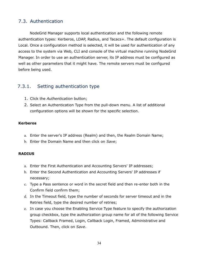
7.3. Authentication
NodeGrid Manager supports local authentication and the following remote
authentication types: Kerberos, LDAP, Radius, and Tacacs+. The default configuration is
Local. Once a configuration method is selected, it will be used for authentication of any
access to the system via Web, CLI and console of the virtual machine running NodeGrid
Manager. In order to use an authentication server, its IP address must be configured as
well as other parameters that it might have. The remote servers must be configured
before being used.
7.3.1. Setting authentication type
1. Click the Authentication button;
2. Select an Authentication Type from the pull-down menu. A list of additional
configuration options will be shown for the specific selection.
Kerberos
a. Enter the server's IP address (Realm) and then, the Realm Domain Name;
b. Enter the Domain Name and then click on Save;
RADIUS
a. Enter the First Authentication and Accounting Servers' IP addresses;
b. Enter the Second Authentication and Accounting Servers' IP addresses if
necessary;
c. Type a Pass sentence or word in the secret field and then re-enter both in the
Confirm field confirm them;
d. In the Timeout field, type the number of seconds for server timeout and in the
Retries field, type the desired number of retries;
e. In case you choose the Enabling Service Type feature to specify the authorization
group checkbox, type the authorization group name for all of the following Service
Types: Callback Framed, Login, Callback Login, Framed, Administrative and
Outbound. Then, click on Save.
35
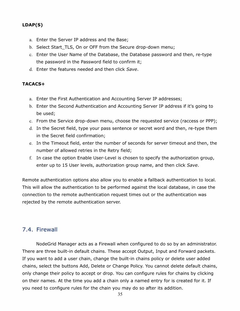
LDAP(S)
a. Enter the Server IP address and the Base;
b. Select Start_TLS, On or OFF from the Secure drop-down menu;
c. Enter the User Name of the Database, the Database password and then, re-type
the password in the Password field to confirm it;
d. Enter the features needed and then click Save.
TACACS+
a. Enter the First Authentication and Accounting Server IP addresses;
b. Enter the Second Authentication and Accounting Server IP address if it's going to
be used;
c. From the Service drop-down menu, choose the requested service (raccess or PPP);
d. In the Secret field, type your pass sentence or secret word and then, re-type them
in the Secret field confirmation;
e. In the Timeout field, enter the number of seconds for server timeout and then, the
number of allowed retries in the Retry field;
f. In case the option Enable User-Level is chosen to specify the authorization group,
enter up to 15 User levels, authorization group name, and then click Save.
Remote authentication options also allow you to enable a fallback authentication to local.
This will allow the authentication to be performed against the local database, in case the
connection to the remote authentication request times out or the authentication was
rejected by the remote authentication server.
7.4. Firewall
NodeGrid Manager acts as a Firewall when configured to do so by an administrator.
There are three built-in default chains. These accept Output, Input and Forward packets.
If you want to add a user chain, change the built-in chains policy or delete user added
chains, select the buttons Add, Delete or Change Policy. You cannot delete default chains,
only change their policy to accept or drop. You can configure rules for chains by clicking
on their names. At the time you add a chain only a named entry for is created for it. If
you need to configure rules for the chain you may do so after its addition.
36
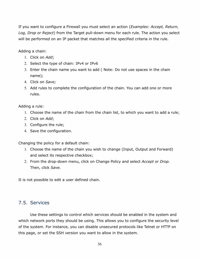
If you want to configure a Firewall you must select an action (Examples: Accept, Return,
Log, Drop or Reject) from the Target pull-down menu for each rule. The action you select
will be performed on an IP packet that matches all the specified criteria in the rule.
Adding a chain:
1. Click on Add;
2. Select the type of chain: IPv4 or IPv6
3. Enter the chain name you want to add ( Note: Do not use spaces in the chain
name);
4. Click on Save;
5. Add rules to complete the configuration of the chain. You can add one or more
rules.
Adding a rule:
1. Choose the name of the chain from the chain list, to which you want to add a rule;
2. Click on Add;
3. Configure the rule;
4. Save the configuration.
Changing the policy for a default chain:
1. Choose the name of the chain you wish to change (Input, Output and Forward)
and select its respective checkbox;
2. From the drop-down menu, click on Change Policy and select Accept or Drop.
Then, click Save.
It is not possible to edit a user defined chain.
7.5. Services
Use these settings to control which services should be enabled in the system and
which network ports they should be using. This allows you to configure the security level
of the system. For instance, you can disable unsecured protocols like Telnet or HTTP on
this page, or set the SSH version you want to allow in the system.
37
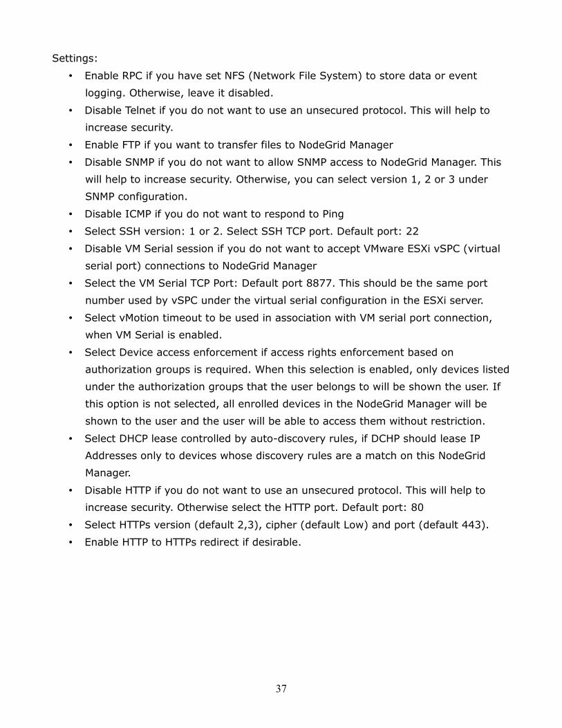
Settings:
• Enable RPC if you have set NFS (Network File System) to store data or event
logging. Otherwise, leave it disabled.
• Disable Telnet if you do not want to use an unsecured protocol. This will help to
increase security.
• Enable FTP if you want to transfer files to NodeGrid Manager
• Disable SNMP if you do not want to allow SNMP access to NodeGrid Manager. This
will help to increase security. Otherwise, you can select version 1, 2 or 3 under
SNMP configuration.
• Disable ICMP if you do not want to respond to Ping
• Select SSH version: 1 or 2. Select SSH TCP port. Default port: 22
• Disable VM Serial session if you do not want to accept VMware ESXi vSPC (virtual
serial port) connections to NodeGrid Manager
• Select the VM Serial TCP Port: Default port 8877. This should be the same port
number used by vSPC under the virtual serial configuration in the ESXi server.
• Select vMotion timeout to be used in association with VM serial port connection,
when VM Serial is enabled.
• Select Device access enforcement if access rights enforcement based on
authorization groups is required. When this selection is enabled, only devices listed
under the authorization groups that the user belongs to will be shown the user. If
this option is not selected, all enrolled devices in the NodeGrid Manager will be
shown to the user and the user will be able to access them without restriction.
• Select DHCP lease controlled by auto-discovery rules, if DCHP should lease IP
Addresses only to devices whose discovery rules are a match on this NodeGrid
Manager.
• Disable HTTP if you do not want to use an unsecured protocol. This will help to
increase security. Otherwise select the HTTP port. Default port: 80
• Select HTTPs version (default 2,3), cipher (default Low) and port (default 443).
• Enable HTTP to HTTPs redirect if desirable.
38
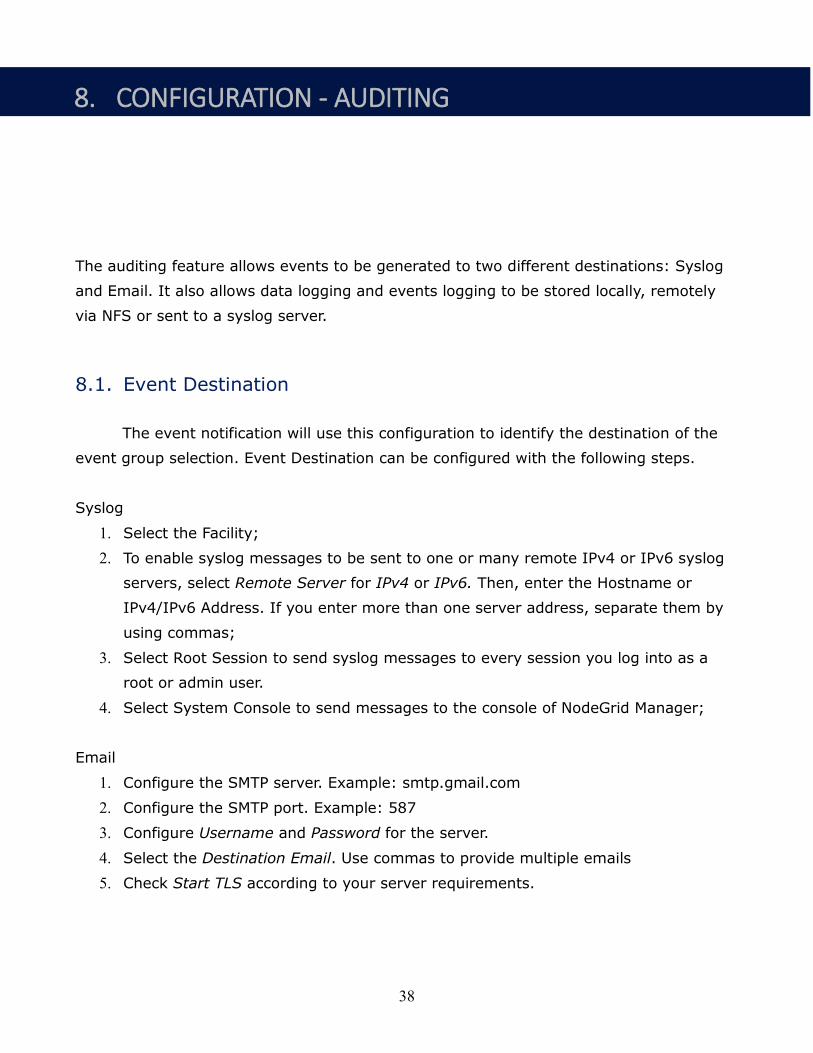
The auditing feature allows events to be generated to two different destinations: Syslog
and Email. It also allows data logging and events logging to be stored locally, remotely
via NFS or sent to a syslog server.
8.1. Event Destination
The event notification will use this configuration to identify the destination of the
event group selection. Event Destination can be configured with the following steps.
Syslog
1. Select the Facility;
2. To enable syslog messages to be sent to one or many remote IPv4 or IPv6 syslog
servers, select Remote Server for IPv4 or IPv6. Then, enter the Hostname or
IPv4/IPv6 Address. If you enter more than one server address, separate them by
using commas;
3. Select Root Session to send syslog messages to every session you log into as a
root or admin user.
4. Select System Console to send messages to the console of NodeGrid Manager;
1. Configure the SMTP server. Example: smtp.gmail.com
2. Configure the SMTP port. Example: 587
3. Configure Username and Password for the server.
4. Select the Destination Email. Use commas to provide multiple emails
5. Check Start TLS according to your server requirements.
8. CONFIGURATION - AUDITING
39
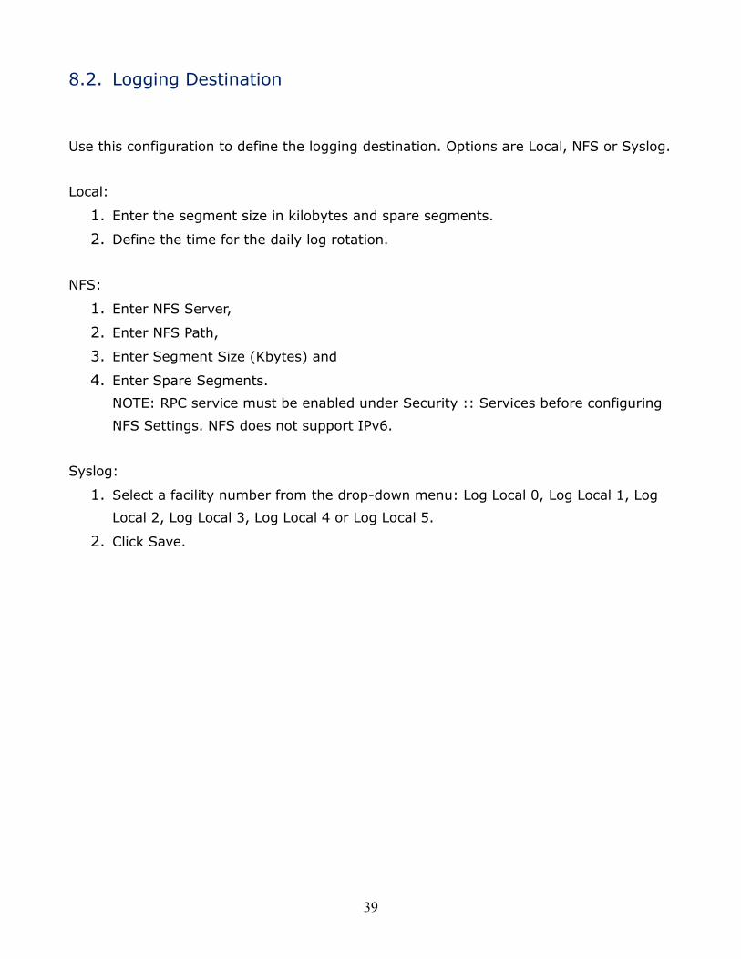
8.2. Logging Destination
Use this configuration to define the logging destination. Options are Local, NFS or Syslog.
Local:
1. Enter the segment size in kilobytes and spare segments.
2. Define the time for the daily log rotation.
NFS:
1. Enter NFS Server,
2. Enter NFS Path,
3. Enter Segment Size (Kbytes) and
4. Enter Spare Segments.
NOTE: RPC service must be enabled under Security :: Services before configuring
NFS Settings. NFS does not support IPv6.
Syslog:
1. Select a facility number from the drop-down menu: Log Local 0, Log Local 1, Log
Local 2, Log Local 3, Log Local 4 or Log Local 5.
2. Click Save.
40
Our Technical Support staff are standing by to provide assistance in case you have any
operational or installation issues regarding to your licensed NodeGrid Manager product.
In order to be assisted in the fastest way possible, follow the steps below:
1. Verify the relevant section of this manual to see if the problem can be solved by
following the recommended procedures shown;
2. Visit our Support Website www.zpesystems.com/support to submit an online
service request or to find the Technical Support location closest to you.
For Online help documentation, go to www.zpesystems.com
ZPE Systems, the ZPE Systems logo, NodeGrid, and NodeGrid Manager are registered Trademarks of ZPE Systems or its affiliates in the U.S.
and other countries. All other marks are the property of their respective owners.
© 2013-2014 ZPE Systems, INC – DO100-001
9. TECHNICAL SUPPORT

![MPC8548E Configurable Development System … Configurable Development System Reference Manual, ... [4:0] ... MPC8548E Configurable Development System Reference Manual,](https://img.pdfslide.us/doc/110x75/5af028337f8b9ac62b8e4c0e/mpc8548e-configurable-development-system-configurable-development-system-reference.jpg)