Embed Size (px)
Citation preview

USER GUIDE
SW2400 3G ENABLED VEHICLE RECORDER
Thank you for purchasing the SW2400 Vehicle Recorder. Please ensure that you read and understand this USER GUIDE
and use it before connecting and installing this Recorder. Please store the USER GUIDE in an easily accessible location.
VER 1.0.0 1st Edition

INDEX
SAFETY ADVICE
3
GPS RECEPTION 4
CONTENTS 5
INTRODUCTION 6
FINCTIONS 8
LEDS &BUZZER SPECIFICATION 10
Installation 11
CONFIGURATION TOOL USER GUIDE 12 INITIALIZE SD CARD 14 DEVICE SETTINGS 15 RECORD SETTINGS 16 EVENT SETTINGS 17 INFO. SETTINGS 18 CONNECTIVITY SETTINGS 19 SERVER SETTINGS 20
SOFTWARE USER GUIDE 21 PC VIEWER SOFTWARE SETTINGS 23 OPEN THE SD CARD 24 OPEN FILES 25 PLAYBACK 26 DRIVE DATA 27 TRACKING MAP 28 EVENT SEARCH 29 PRIVACY SETTINGS 30 SAVE JPEG AND AVI FILE 31 PRINT IMAGE 32 BACKING UP FILES 33 BACKUP DATA LIST AND EXPORT 34
SPECIFICATION 35
APPENDIX RECORDING TIME TABLE 36
APPENDIX UPGRADE 37
TECHNICAL SUPPORT AND WARRANTY 38
2

SAFETY ADVICE
CAUTION
RISK OF ELECTRIC SHOCK DO NOT OPEN
CAUTION: TO REDUCE THE RISK OF ELECTRIC SHOCK, DO NOT REMOVE COVER.
NO USER‐SERVICEABLE PARTS INSIDE. REFER SERVICING TO QUALIFIED SERVICE PERSONNEL.
Please make sure you follow the safety advice/instructions given in the user guide.
Caution RISK OF EXPLOSION IF BATTERY IS REPLACED BY AN INCORRECT TYPE. DISPOSE OF USED BATTERIES ACCORDING TO THE INSTRUCTIONS. Battery for RTC(Real Time Clock) inside
Caution Install the product where it does not block driver’s visibility and where there is no airbag installed. This could cause an accident or might injure passengers in case of accident
Caution Damages due to production malfunction, loss of data, or other damages occurring while using this product shall not be the responsibility of the manufacturer. Although the product is a device used for recording videos, the product may not save all videos in the case of a malfunction. In the case of an accident, the sensor may not recognize the shock when the impact is light and as a result it may not begin recording automatically.
WARNING: TO PREVENT FIRE OR ELECTRIC SHOCK HAZARD, DO NOT EXPOSE
THIS APPLIANCE TO RAIN OR MOISTURE.
3

GPS RECEPTION
1. Activate the product in an area without large buildings to improve GPS reception.
The commercial purpose GPS has the average rage error of more than 15 meters and the range error could be more than 100 meters due to environmental conditions like buildings, roadside trees etc.
2. The temperature range for optimum operation of the GPS receiver in your car is ‐10 ~ 50°C.
3. When using the product for the first time or after a long
period (more than three days), it may take a little longer to recognize your current location.
It may take between five and thirty minutes to get GPS reception.
GPS reception may be impaired under the following circumstances
1) If there is an object at the end of the GPS antenna
2) If your vehicle has metallic elements on the windshields
3) If equipment generating electromagnetic waves that interfere with the GPS
signal is installed in the vehicle e.g.: Other GPS devices such as a certain type of wireless activated alarms, MP3 and CD players and camera alarms using GPS.
4) If you are using a receiver connected by cable, electric interference can be
avoided by simply changing the location of the receiver (antenna).
5) On heavily overcast or cloudy days, if the vehicle is in a covered location such as under a bridge or raised roadway, in a tunnel, an underground roadway or parking area, inside a building or surrounded by high‐rise buildings.
6) If GPS signal reception is poor, it may take longer to locate your current
position when the vehicle is moving than when it is stationary.
4

CONTENTS
Power Cable
SW2400 Vehicle Recorder
Sticker for Windscreen mounting (double sided tape x2)
User Guide
Wire Splice clips (x5)
Sticker for Angle Lock
(Void sticker x2)
Torx screw (x1) SD Cover (x1)
5

INTRODUCTION
FRONT
Bracket (GPS/GLONASS inside)
Camera Lens
Cable (95cm)
SIDE
IMEI Number
SD Memory Card Slot
SIM Slot (Mini SIM)
Lock using Torx screw
6

INTRODUCTION
BACK
G‐Sensor Calibration button
PANIC Button
Record LED BLUE LED
Communication LED Green LED
POWER CABLE
Black (Ground)
Red (Power Battery +)
White (Power ACC + )
Green (Alarm In, NC/NO), (External panic button+ )
Black (Ground), (External panic button+ )
Orange (Alarm In, Voltage)
Yellow (Alarm out), Low(0V) to High (5V) 2seconds
External Panic Button (optional Item)
Cable length: 2m90cm Button Case Size: 18 x39x10 mm
7

FUNCTIONS
Automatic Booting
Once the SW2400 has been wired to your car power source the SW2400 will be boot up, this will take around 1 minute for the unit to be ready to record.
The default setting for record is the continuous recording at 30fps, 720P resolution. On this setting the SD card storage may be used up quicker and depending on the settings, overwrite or stop recording when full. To avoid losing valuable data, back up data to a separate storage or PC device after any incidents.
NOTE: The unit will not start recording immediately after power on. It takes around 1 minute for the built‐in power backup system to charge. Thereafter, the internal flash memory will be ready to record.
Continuous Record (When Record mode set as “Continuous”)
This is the default mode for recording. In this setting the unit will begin recording after boot up and record the entire time the unit is powered. The resolution and frame rates can be set as per your requirements. You can change the configuration of the recording using the SW2400 Software. To do this, please see the ‘Settings’ section on page 16.
Event Record (When Record mode set as “Event”)
The unit will record when triggered by either an impact or a push of the ‘PANIC’ button. Each event file contains up to 20 seconds prior & up to 20 seconds post event. And the event file can be extended by 2nd trigger during event record. When events are triggered continuously, for every event, 20 seconds post‐recording from the time of the event will be added to the event data file with a maximum recording time of 3 minutes. When this 3 minutes is reached, the file will be split and a new file will be created but the data will be continuous.
Dual Record (Continuous & Event Record)
The continuous record fps is 1fps and the file will be stored on the “Normal” folder. Event record will work according to the Fps setting for example 30frames per second recording and the file will be stored on the “Event” folder
Drive Data (DRV file)
The DRV (Drive Data) file will be recorded during driving even if there are no events or video. The DRV file consists of GPS and G‐sensor data and it helps to find specific data or driving behaviors. The DRV file overwrites the oldest data. The DVR files will be made every 10 minutes.
8

FUNCTIONS
G‐Sensor Calibration
G‐Sensor Calibration is needed after installing the SW2400.
1. Install the unit and park the vehicle on a flat surface . 2. Turn on the unit and press the small red button three seconds. 3. Then calibration will be done with “beep” sound.
Built‐in power backup (Super Capacitor)
When power to the unit is interrupted, SW2400 creates the last file using the internal Super Capacitor.
Time and Date
There are no time and date settings as the SW2400 get’s this information from the GPS satellite's.
SD Memory Card Format
Please format [initialize] the SD card using the “Configuration Tool SW2400” software.
Safely Removal SD Card
Power off vehicle and take out SD memory card
Turn off the power and then check the BLUE LED light. Once the LED light is not on, you can now safely remove the SD memory card.
9

LEDS & BUZZER SPECIFICATION
BLUE LED (RECORD) GREEN LED (COMMUNICATION) FRONT LED Buzzer
10

INSTALLATION
Park your vehicle on a flat level surface. Turn off the engine before installing the SW2400.
Attach the SW2400 using the provided double sided 3M tape. The surface must be clean and dry before you install. We recommended to install the product behind the rear view mirror on the front windshield.
NOTE: The 3M adhesive tape will not stick well with dust or oil, etc. Please make sure the surface is clean before applying.
Adjust camera view. Make sure the lens has an unobstructed view. Check from outside the vehicle to check the camera angle, you can adjust the angle via the bracket teeth.
Arrange the power cord neatly alongside of the windshield and door pillar trim.
The SW2400 requires a continuous 12/24 volt power source from the vehicle.
The cable supplied will allow you to hard wire the SW2400 unit to the fuse box of your vehicle.
Connect the “red cable (+)” to a fuse (see picture below). It should be connected to a fuse that has power when you start the engine.
The ground cable should be contacted at the car body or battery negative.
Start on the car after installation.
11

CONFIGURATION TOOL USER GUIDE
Configuration Tool SW2400 Software
PC SYSTEM REQUIREMENT
Recommended PC specifications for PC Viewer Software
OS Windows Vista. Windows 7, Windows 8/8.1
CPU Core 2 Duo 2.5GHz or Higher
RAM 2GB or Higher
Interface SD Memory Card Reader
HDD
Free space
Install : 55MB or Higher Backup : 4GB or Higher
Display 1024 x 768 pixel/True Color or higher
If the PC does not meet the minimum system requirement, the PC Viewer Software may not function properly.
12

SOFTWARE INSTALLATION
The Configuration Tool SW2400 Software is on the provided SD card. (Also available on our website.)
1. Connect the SD card into your PC (if your computer does not have and SD card slot use the USB SD card reader) and open the “My Computer”
2. Right‐click the “FHDRM” drive and select [Open]
3. Double click [configtool(FW1.0.0_PC1.0.0.0_V1).EXE] in the [pcsw] folder.
4. Select the language and then follow the dialog box prompts.
5. The “Configuration Tool SW2400” icon will be displayed on your desktop.
NOTE: To Un‐install the Configuration Tool SW2400 Software Make sure the program is not running and open the ‘Control Panel’ Select ‘Remove Program’ and remove the Configuration Tool SW2400 Software.
13
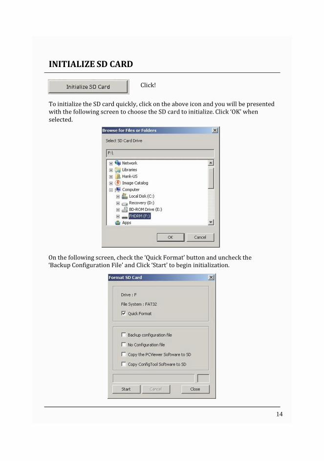
INITIALIZE SD CARD
Click!
To initialize the SD card quickly, click on the above icon and you will be presented with the following screen to choose the SD card to initialize. Click ‘OK’ when selected.
On the following screen, check the ‘Quick Format’ button and uncheck the ‘Backup Configuration File’ and Click ‘Start’ to begin initialization.
14

DEVICE SETTINGS
Cam Title Use the alphabet and numbers to rename (max 10 digits) the cameras. The new names will be displayed on the live screen and all recordings. Audible Camera Chime: Turn the Chime on or off Connection Type : Set the power supply type Delayed Power Shutdown: Set delayed power shutdown time. G‐Sensor Sensitivity: The shock sensor sensitivity can be set to ‘Simple setting Mode’ or ‘Custom’. Set to easy allows you to set the sensitivity to 9 (High), 5 (Medium) or 1 (Low). In custom set, you can set 3 different shock sensor values individually. Auto adjust G‐Sensor to Vehicle speed Once it checked, SW2400 will automatically decrease the G‐Sensor sensitivity at higher vehicle speeds to compensate for the naturally added G‐forces that are experienced due to velocity.
15

RECORD SETTINGS
Resolution VGA (640x480), 720P (1280x720), 1080p HD (1920x1080). Frame Rate Adjust the frame rate from 30fps, 15fps, 10fps, 5~1fps Quality Adjust the picture quality from Standard, High, Super Record Mode Event (Automatically starts recording by G‐sensor or Panic button.) Continuous (Always recording when powered by DC 12/24V.) Dual (The continuous record fps is 1fps and Event record will work according to the Fps setting.) Overwrite Recordings This function allows the unit to overwrite old files on the SD Card automatically. You can overwrite the continuous, panic or G‐Sensor recorded files. Pre‐Event / Post‐Event Adjust the Pre/Post Event time from 5 seconds to 20seconds Drive Data GPS data & G‐Sensor data will be recorded with videos and at the same time, GPS data & G‐Sensor data will be recorded separately, we call it as ‘Drive data(drv file)’. Adjust Drive Data duration from “about 1 day” to “about 30 days”.
16

EVENT SETTINGS
Event settings You can set the unit to record when triggered by the G‐Sensor, Panic Button and GPS Speed Limit and Alarm Inputs. And you can set the Alarm out duration per each event.
17

INFO. SETTINGS
This option allows you to adjust the Time Zone, GPS Time synchronization, set your Vehicle ID and also the Driver ID.
18

CONNECTIVITY SETTINGS
Set the Service Type as Sever to use 3G connection.
Adjust the settings like Dial No., APN, password, User ID, Authentication etc.
Please refer to the Sim Card supplier website for these settings.
19
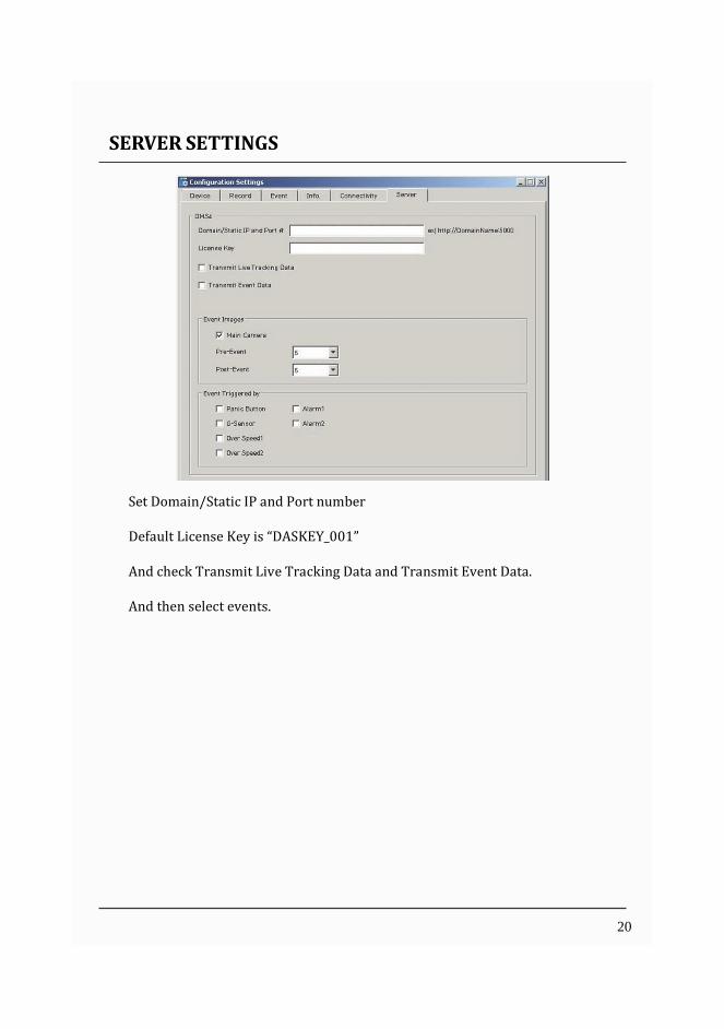
SERVER SETTINGS
Set Domain/Static IP and Port number
Default License Key is “DASKEY_001”
And check Transmit Live Tracking Data and Transmit Event Data.
And then select events.
20

SOFTWARE USER GUIDE
PC Viewer Software
PC SYSTEM REQUIREMENT
Recommended PC specifications for PC Viewer Software
OS Windows Vista. Windows 7, Windows 8/8.1
CPU Core 2 Duo 2.5GHz or Higher
RAM 2GB or Higher
Interface SD Memory Card Reader
HDD
Free space
Install : 55MB or Higher Backup : 4GB or Higher
Display 1024 x 768 pixel/True Color or higher
If the PC does not meet the minimum system requirement, the PC Viewer Software may not function properly.
21

SOFTWARE INSTALLATION
The PC Viewer Software is on the provided SD card. (Also available on our website.)
1. Connect the SD card into your PC (if your computer does not have and SD card slot use the USB SD card reader) and open the “My Computer”
2. Right‐click the “FHDRM” drive and select [Open]
3. Double click [SETUP.EXE] in the [pcsw] folder.
4. Select the language and then follow the dialog box prompts.
5. The “PC Viewer SW2400” icon will be displayed on your desktop.
NOTE: To Un‐install the PC Viewer Software Make sure the program is not running and open the ‘Control Panel’ Select ‘Remove Program’ and remove the PC Viewer Software.
22

PC VIEWER SOFTWARE SETTINGS
Viewing settings
This setting is for the PC Viewer Software itself. To set the Recorder, refer to page 15.
Click the ‘Password’ button. Password for the PC Viewer Software can be set with any number between 1000‐9999. The ‘speed’ & ‘date’ formats will be set automatically according to the PC Windows setting. However it can be changed with this software setting menu. Last Layout: The program will launch with the same layout as it was when it was closed. Default Layout: The program will launch with the Default Layout Drive Data Settings The graph scales for the Drive Data Window will be modified according to the Settings.
23
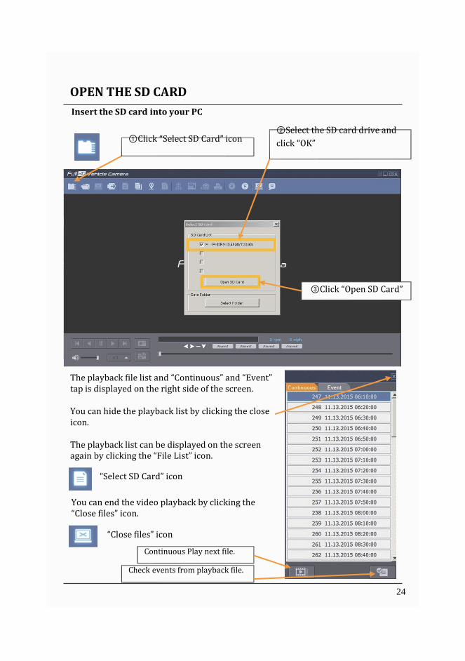
OPEN THE SD CARD
Insert the SD card into your PC
① Click “Select SD Card” icon
② Select the SD card drive and
click “OK”
③ Click “Open SD Card”
The playback file list and “Continuous” and “Event” tap is displayed on the right side of the screen.
You can hide the playback list by clicking the close icon.
The playback list can be displayed on the screen again by clicking the “File List” icon.
“Select SD Card” icon
You can end the video playback by clicking the “Close files” icon.
“Close files” icon
Continuous Play next file.
Check events from playback file.
24

OPEN FILES
If you want to play a specific file that has been backed up on the PC or SD Card, Click the “Open files” icon
“Open files” icon
Select the MDT file you want to play and click “Open”. The image of the selected file will then be displayed and you can click the “Play” button to play the file.
“Eject SD Card” icon
When finished, click “Eject SD Card” icon and remove the SD card from your PC.
Or please use “Safely Remove Hardware and Eject Media” button in your PC.
25

PLAYBACK
Camera title ‐ Resolution GPS Speed Display Frame / Total frames number
Record Mode
Vehicle ID, Driver ID
Previous Image
Reverse Pause
Play Next Image
Capture Screen
Record Video
Volume
Playback Speed Control
Signal / Alarm Indicator
Left, Right, Brake, Reverse
26

DRIVE DATA
“Drive Data” icon
The default setting only displays the G‐sensor graphs but other information may be added by checking the boxes in the upper part of the screen.
G‐Sensor: (X axis: red, Y axis: green, Z axis: blue, based on the positioning of the main unit) is shown with the data reference point zero‐point calibrated and positive shocks as (+) and negative shocks as (‐).
G sensor X value: Front & Back (like Quick brake or Quick Start) G sensor Y value: Left & Right (like Quick Turn) G sensor Z value: Up & Down (like prominence and depression)
Speed: GPS measured speed is displayed in grey. The speed‐pulse measured speed is not support.
RPM: The RPM is not support. ALARM: The alarms are displayed on the bottom of the screen with the grey bar meaning the trigger is activated.
27

TRACKING MAP
“Tracking Map” icon
The route taken will be displayed on the Google map.
The playback position will be shown on the map with the orange arrow.
The blue markings show the route taken.
To see the route and position on the Google map, the GPS data should be recorded with video.
To see the map, the PC should be connected to the internet.
28

EVENT SEARCH
“Event Search” icon
The “Event Search” help to find a specific data quickly.
Select “Search Range” and select “Search Conditions”
And then click Search button.
Choose an event from the searched list and click “Go to Video” to see the video.
29

PRIVACY SETTINGS
“Privacy Settings” icon
Set the mosaic area on the video for privacy protection.
When backing up the data as a JPG or AVI format and playing in the Viewer software, you are able to make a mosaic processing on the area you have set.
To do this, put the pause the video and click the ‘Privacy settings’ button. The privacy setting screen will pop up.
Blur out the area you wish to protect by left‐clicking on the sections. You can select multiple areas. You can also unselect, selected areas by right‐clicking the blurred areas. To select all or clear all, click on the ‘Select all’ or ‘UnSelect All’ buttons on the bottom, respectively.
30

SAVE JPEG AND AVI FILE
Pause the playback and click “Save JPG” icon to make JPG images.
“Save JPG” icon
Pause the playback and click “Save AVI” icon to make an AVI file.
“Save AVI” icon
31

PRINT IMAGE
Pause the playback and click “Print Image” icon.
“Print Image” icon
Type Subject and Memo
Alter the printer settings to change paper size/orientation etc.
32

BACKING UP FILES
Back up the recorded data on your PC. There is an option to store data by type to easy management of data.
“Backup Data” icon
The start time is when the video was paused and cannot be changed once you start this process. Set the time you wish to backup and input Title and Memo. And input Type and then click [Start]. The maximum amount of time you can back up is one hour.
33

BACKUP DATA LIST AND EXPORT
You can use the data backup list to play data files easier that have been backed up.
“Backup Data List and Export” icon
Choose the folder where the backup files are at the bottom of the screen. (It will automatically show the last folder that was accessed.) Then, select the type by scrolling down the options. The files are listed showing the “Date/Time, Vehicle ID, Driver ID, Memo Title”. Check the box next to the file you wish to play back and click ‘OK’.
34

SPECIFICATION
Image sensor 1/3” 3 Megapixel CMOS Sensor
DSP Standard DSP
Angle of View 170° (H:139.5°, V : 71.5° ±5% )
Band support WCDMA Band1(2,100MHz)/ Band8 (900MHz)
Max Data Rate UL:5.76Mbps, DL : 7.2Mbps
Video resolution 1080p HD (1920x1080) 720P (1280x720), VGA (640x480)
Recording Speed Up to 30 fps
Recording Mode Continuous , Event, Dual Mode
Memory Supports Cards of up to 32GB (Class 10)
GPS/GLONASS Internal GPS /GLONASS
G‐Sensor Internal 3‐axis G‐sensor
Gyro 3Axis(X,Y,Z), output rate:100 Hz,
RTC Internal battery
Speaker Recording start, error
Audio Internal Microphone
Alarm In/Out 2 x Alarm In, 1 x Alarm Out
LED Record,(Blue LED) Communication(Red LED)
Supper Capacitor Enable recording of last file and shut down
PC software Supplied
Power input 12V to 24V DC permeant wiring kit Input Voltage: DC 5V, 3A
Delayed Power Shutdown
Supports Delayed Power Shutdown
Power consumption 15W
Size / Weight 91mm X 56mm X 56mm (w/o Bracket) , 150g
Operation Temp. ‐10℃~55℃
35

APPENDIX Recording time table
This table is a guideline only. Actual results may very depending on a variety of factors on the road.
36

APPENDIX (Upgrade)
NOTE: To get the upgrade firmware, please contact your Silent Witness.
1. Prepare Firmware
Make a folder called [program] on the SD root folder as shown below,
Copy “XXXXXX_x.x.x.img” file to the SD card [program] folder.
2. Upgrade SW2400
Insert the prepared SD card to SW2400 unit and turn on the power.
The Blue & Red LED will blink while the unit is upgrading. It will also ‘beep’ continuously. Upgrading the unit usually takes about 30 seconds.
Warning: Do not turn off the power during upgrading. If the upgrade fails, the SW2400 unit should be returned to Silent Witness.
Once the upgrading is finished, the unit will automatically turn off and on the power.
37

Technical Support & Warranty
TECHNICAL SUPPORT
For Technical Support, please contact Silent Witness
LIMITED WARRANTY
This product is supplied with 1 year warranty. The Warranty excludes products That have been misused, (including accidental damage) and damage caused by normal wear and tear. In the unlikely event that you encounter a problem with this product, it should be returned to the place of purchase.
38


![User manual DATA RECORDER SRD-N16 - RS … · I. USER MANUAL FOR DATA RECORDER ... Pt500 or Pt1000 standards for ... User manual - DATA RECORDER SRD-N16 and cooperating software [^]](https://img.pdfslide.us/doc/110x75/5b82c34e7f8b9adc698b9dd1/user-manual-data-recorder-srd-n16-rs-i-user-manual-for-data-recorder-.jpg)