Embed Size (px)
Citation preview
A776–UG00001 B
User Guide
A776 Two-Color Hybrid Thermal/Impact Printer
• L
LOY
D'S
REG
ISTER QUALITY A
SSUR
AN
CE
I S O 9 0 0 1
New TPG LogoEZ® colorization utility information included.
A776 Printer without Imaging
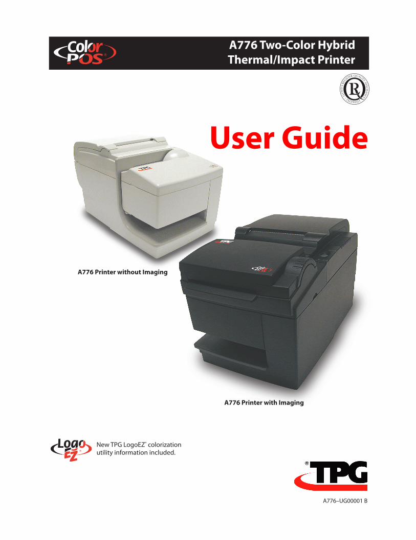
A776 Printer with Imaging
Federal Communications Commission (FCC) Radio Frequency Interference Statement WarningChanges or modifications to this unit not expressly approved by the party responsible for compliance could void the user’s authority to operate the equipment.
NoteThis equipment has been tested and found to comply with the limits for a Class A digital device, pursuant to Part 15 of the FCC Rules. These limits are designed to provide reasonable protection against harmful interference when the equipment is operated in a commercial environment. This equipment generates, uses, and can radiate radio frequency energy and, if not installed and used in accordance with the instruction manual, may cause harmful interference to radio communications. Operation of this equipment in a residential area is likely to cause harmful interference in which case the user will be required to correct the interference at his own expense.
Information to the UserThis equipment must be installed and used in strict accordance with the manufacturer’s instructions. However, there is no guarantee that interference to radio communications will not occur in a particular commercial installation. If this equipment does cause interference, which can be determined by turning the equipment off and on, the user is encouraged to contact TPG immediately.TPG, Inc. is not responsible for any radio or television interference caused by unauthorized modification of this equipment or the substitution or attachment of connecting cables and equipment other than those specified by TPG. The correction of interferences caused by such unauthorized modification, substitution or attachment will be the responsibility of the user.WARNING! In order to ensure compliance with the Product Safety, FCC and CE marking requirements, you must use the power supply, power cord, and interface cable which are sold for use with this product or which meet the following parameters:
Power SupplyUL® Listed (QQGQ), NEC Class 2 power supply with SELV (Secondary Extra Low Voltage), non-energy hazard output, limited energy source, input rated 100-240 Vac, 1.5/0.8 A, 50/60 Hz, output rated 24 Vdc, 2.3 A for 55-watt unit; 100-200 Vac, 2.0 A, 50/60 Hz, output rated 24 Vdc, 3.125 A for 75-watt unit.Use of this product with a power supply other than the TPG power supply will require you to test the power supply and TPG printer for FCC and CE mark certification.
Communication Interface CableA shielded (360 degree) interface cable must be used with this product. The shield must be connected to the frame or earth ground connection or earth ground reference at EACH end of the cable.Use of a cable other than described here will require that you test the cable with the TPG printer and your system for FCC and CE mark certification.
Power CordA UL® listed, detachable 3-wire power cord must be used; where the third wire is the protective earthing conductor. For applications where the power supply module may be mounted on the floor, a power cord with Type SJT marking must be used. For applications outside the US, power cords which meet the particular country’s certification and application requirements should be used.Use of a power cord other than described here may result in a violation of safety certifications which are in force in the country of use.
Industry Canada (IC) Radio Frequency Interference StatementThis Class A digital apparatus meets all requirements of the Canadian Interference-Causing Equipment Regulations.Cet appareil numérique de la classe A respecte toutes les exigences du Règlement sur le matériel brouilleur du Canada.
Voluntary Control Council for Interference (VCCI) Radio Frequency Interference StatementThis is a Class A product based on the standard of the Voluntary Control Council for Interference by Information Technology Equipment (VCCI). If this equipment is used in a domestic environment, radio disturbance may arise. When such trouble occurs, the user may be required to take corrective actions.
DisclaimerInformation in this document is subject to change without notice. Consult your TPG sales representative for information that is applicable and current. TPG reserves the right to improve products as new technology, components, software, and firmware become available.No part of this document may be reproduced, translated, or transmitted in any form or by any means, electronic or mechanical, for any purpose without the express written permission of TPG.
Copyright © 2005 Transaction Printer Group, Inc. a subsidiary of ATSI Holdings, Inc. All Rights reserved. Patents Pending. All trademarks or registered trade marks are the property of their respective owners. Printed in USA. Product specifications subject to change in order to continue meet the needs of the market.
TrademarksTPG, INC.™, ColorPOS®, and LogoEZ® are trademarks of TPG, Inc., ATSI and its subsidiaries. Microsoft and Windows NT are registered Trademarks of Microsoft Corporation in the U.S.A. and/or other countries. Inside Out Networks, Inside Out, EPIC, and Edgeport are trademarks of Inside Out Networks. All other trademarks and registered trademarks are the property of their respective holders.
Patents: Made under one or more of the following U. S. patents: 4886381, 5579043, 5613787, 5651624, 5713678, 5752779, 5789916, 5800080, 5879090, 5887999, 5975776, 6027266, 6085973, 6089450, 6129465, 6155483, 6404452, 6486902, 6504331, 5749277, 6722754, 6739773, 6784909.
Web Sitehttp://www.tpgprinters.com
Contents
A776 UG00001 B 10/06 A776 Two-Color Thermal/Impact Hybrid Printer: User Guide
i
Contents
Table of Contents
Chapter 1: About This Guide ................................................................................................................. 1
Chapter 2: About the Printer ................................................................................................................. 2The A776 ColorPOS printer without imaging ................................................................... 2
The A776 ColorPOS printer with imaging .......................................................................... 3
Operating systems supported by the imaging feature ................................................. 4
Communication interfaces supported by the imaging feature ................................. 4
User controls for both B780 printers ........................................................................................... 5
Printer Configurations....................................................................................................................... 6Your printer’s ID code ................................................................................................................. 6
Communication interfaces ...................................................................................................... 6
Printer and Imager Specifications ................................................................................................ 6
Chapter 3: Setting up the Printer ......................................................................................................10
Choose a location for printer without imaging .....................................................................10
Choose a location for printer with imaging ............................................................................11
Unpack the printer ...........................................................................................................................12Returning a printer ...................................................................................................................14
Installing new receipt paper for both A776 printers ...........................................................14
Removing and installing a ribbon cassette in A776 printers ............................................15Removing a used ribbon cassette .......................................................................................15
Removing a ribbon on a printer with imaging ...............................................................15
Installing a new ribbon cassette ..........................................................................................15
Connect the cables ..........................................................................................................................16Cash drawer cables ...................................................................................................................16
Communication cables ...........................................................................................................17
Cable routing ..............................................................................................................................19
ii
A776 Two-Color Thermal/Impact Hybrid Printer: User Guide A776 UG00001 B 10/06
Contents
Test printing of both A776 printers ............................................................................................19
Printer and imager configurations .............................................................................................22
Configuring the printer ..................................................................................................................23Communication interface ......................................................................................................24
Diagnostic modes .....................................................................................................................24
Enable or disable data scope mode ...................................................................................25
Enable or disable receipt test mode ...................................................................................26
Setting the printer emulations and software options ................................................27
Chapter 4: Using the Printer ................................................................................................................29
Printing on forms or checks for both A776 printers .............................................................29
Verifying and validating checks for both A776 printers .....................................................31
Inserting checks or cards for imaging (scanning) .................................................................32
Inserting checks for imaging or check verification ..............................................................32
Tips for Avoiding Problems ..........................................................................................................33
Cleaning ...............................................................................................................................................34
Paper jams ...........................................................................................................................................35
Chapter 5: Troubleshooting ................................................................................................................36
Status Indications for both A776 printers ................................................................................36Printer beeps ...............................................................................................................................37
Printer will not print .................................................................................................................37
On-line, paper status, error light flashes ...........................................................................38
Slip-in light does not come on .............................................................................................38
Check print quality poor .........................................................................................................39
Slip station and MICR problems ...........................................................................................40
Knife does not operate ............................................................................................................41
Other conditions ...............................................................................................................................41
Imager conditions ............................................................................................................................41
Contacting a service representative ..........................................................................................41
Contents
A776 UG00001 B 10/06 A776 Two-Color Thermal/Impact Hybrid Printer: User Guide
iii
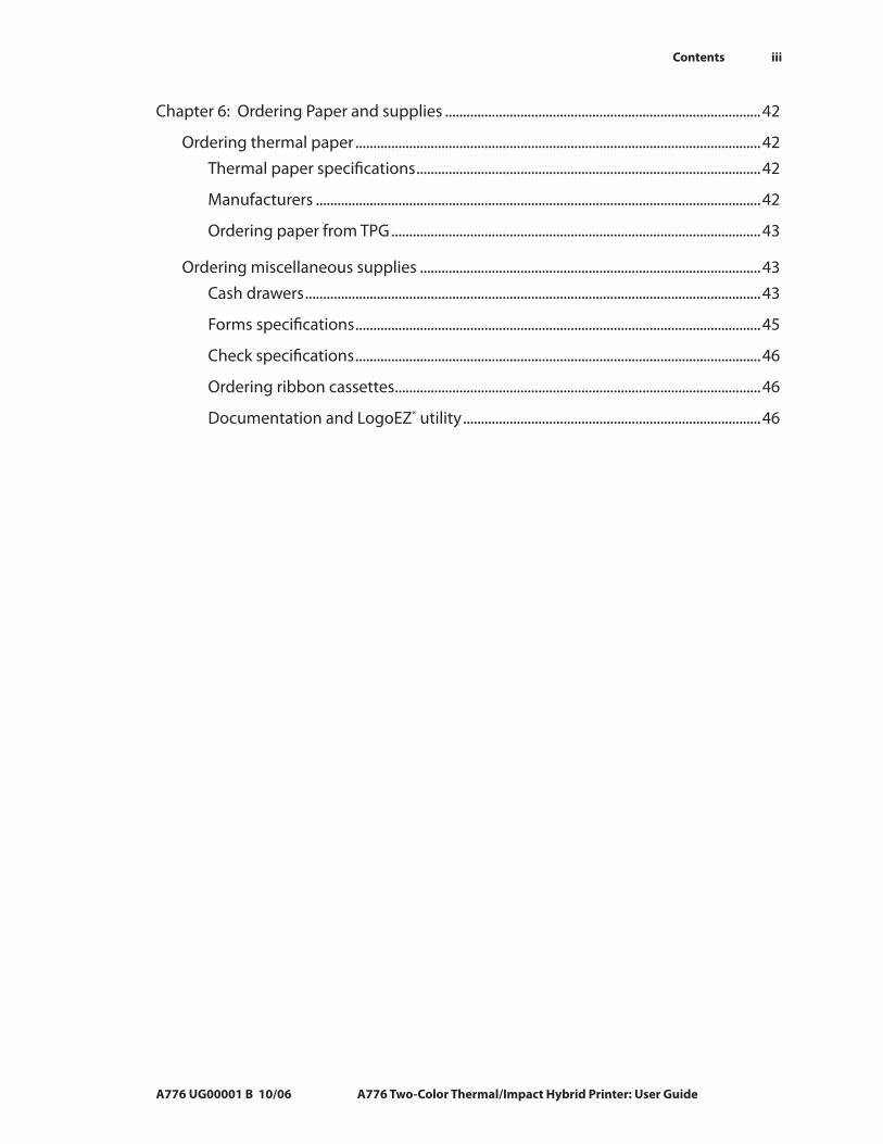
Chapter 6: Ordering Paper and supplies ........................................................................................42
Ordering thermal paper .................................................................................................................42Thermal paper specifications ................................................................................................42
Manufacturers ............................................................................................................................42
Ordering paper from TPG .......................................................................................................43
Ordering miscellaneous supplies ...............................................................................................43Cash drawers ...............................................................................................................................43
Forms specifications .................................................................................................................45
Check specifications .................................................................................................................46
Ordering ribbon cassettes ......................................................................................................46
Documentation and LogoEZ® utility ...................................................................................46
Chapter 1: About this Guide
A776 UG00001 B 10/06 A776 Two-Color Thermal/Impact Hybrid Printer: User Guide
1
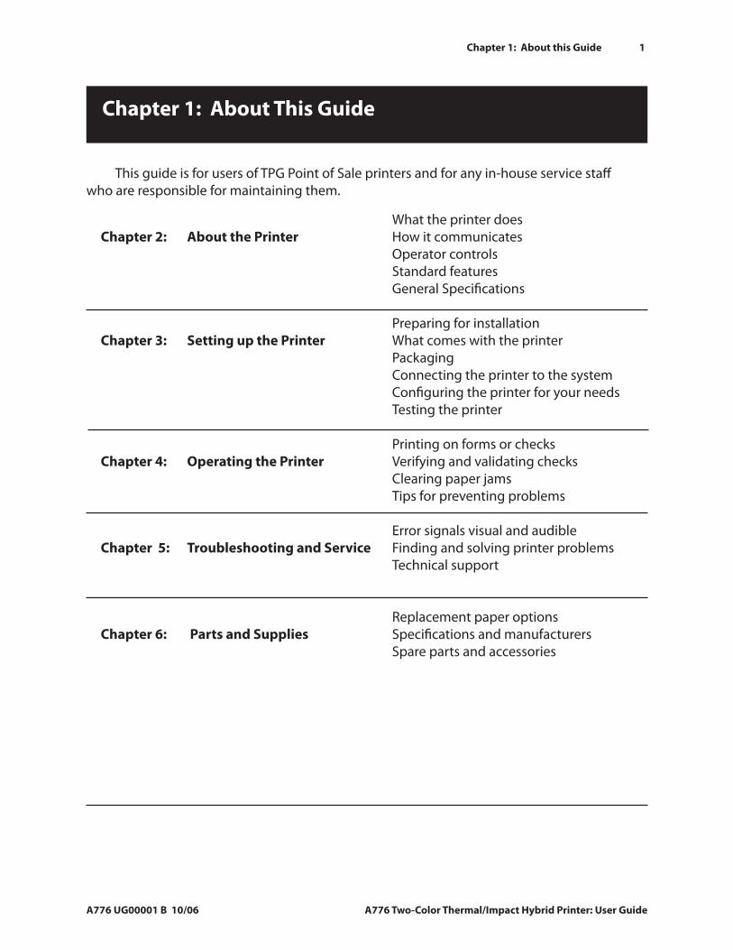
This guide is for users of TPG Point of Sale printers and for any in-house service staff who are responsible for maintaining them.
Chapter 1: About This Guide
Chapter 2: About the Printer
Chapter 3: Setting up the Printer
Chapter 4: Operating the Printer
Chapter 5: Troubleshooting and Service
Chapter 6: Parts and Supplies
What the printer doesHow it communicates Operator controls Standard featuresGeneral Specifications
Preparing for installation What comes with the printerPackaging Connecting the printer to the system Configuring the printer for your needsTesting the printer
Printing on forms or checksVerifying and validating checksClearing paper jamsTips for preventing problems
Error signals visual and audibleFinding and solving printer problems Technical support
Replacement paper optionsSpecifications and manufacturersSpare parts and accessories
2 Chapter 2: About the Printer and Imaging
A776 Two-Color Thermal/Impact Hybrid Printer: User Guide A776 UG00001 B 10/06
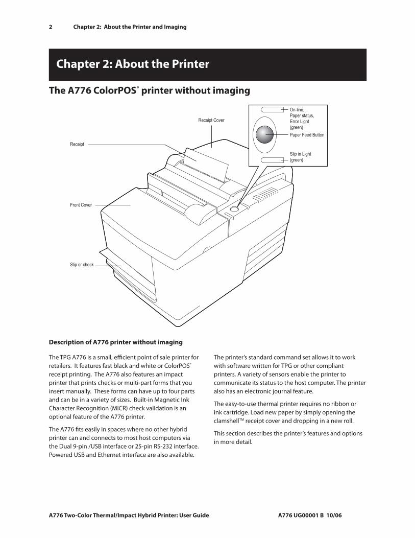
The TPG A776 is a small, efficient point of sale printer for retailers. It features fast black and white or ColorPOS® receipt printing. The A776 also features an impact printer that prints checks or multi-part forms that you insert manually. These forms can have up to four parts and can be in a variety of sizes. Built-in Magnetic Ink Character Recognition (MICR) check validation is an optional feature of the A776 printer.
The A776 fits easily in spaces where no other hybrid printer can and connects to most host computers via the Dual 9-pin /USB interface or 25-pin RS-232 interface. Powered USB and Ethernet interface are also available.
The printer’s standard command set allows it to work with software written for TPG or other compliant printers. A variety of sensors enable the printer to communicate its status to the host computer. The printer also has an electronic journal feature.
The easy-to-use thermal printer requires no ribbon or ink cartridge. Load new paper by simply opening the clamshellTM receipt cover and dropping in a new roll.
This section describes the printer’s features and options in more detail.
Chapter 2: About the Printer
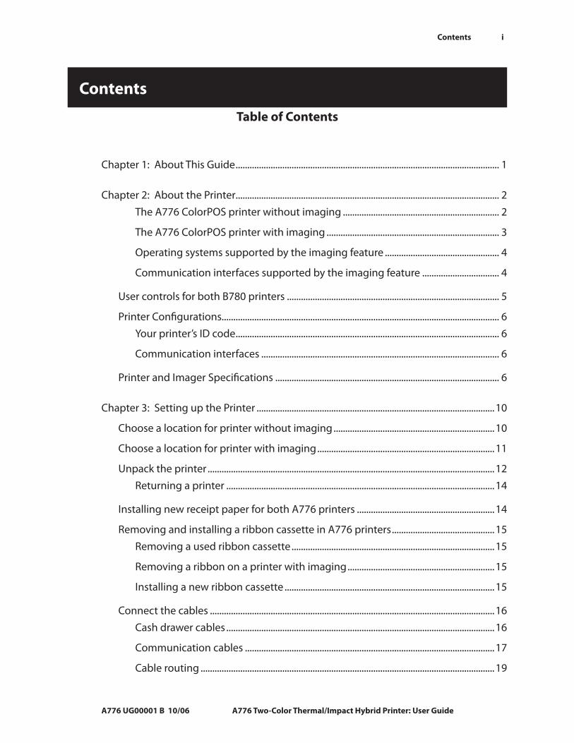
The A776 ColorPOS® printer without imaging
Receipt Cover
Front Cover
Receipt
Slip or check
On-line,
Paper status,
Error Light
(green)
Paper Feed Button
Slip in Light
(green)
Description of A776 printer without imaging
Chapter 2: About the Printer and Imaging
A776 UG00001 B 10/06 A776 Two-Color Thermal/Impact Hybrid Printer: User Guide
3
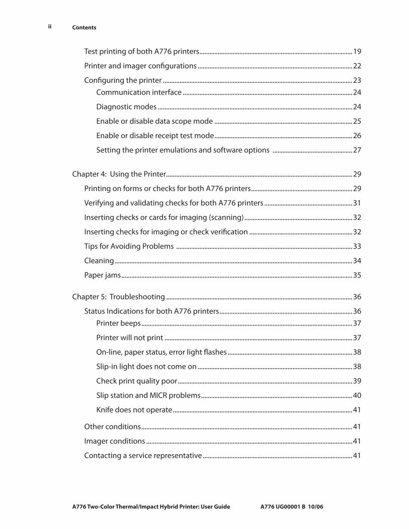
Receipt Cover
Imaging Module Cover
On-line, Paper status,Error Light(green)
Paper Feed Button
Slip in Light (green)
Receipt
Slip or check
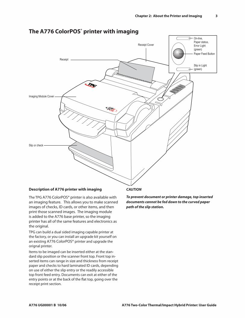
The A776 ColorPOS® printer with imaging
Description of A776 printer with imaging
The TPG A776 ColorPOS® printer is also available with an imaging feature. This allows you to make scanned images of checks, ID cards, or other items, and then print those scanned images. The imaging module is added to the A776 base printer, so the imaging printer has all of the same features and electronics as the original. TPG can build a dual sided imaging capable printer at the factory, or you can install an upgrade kit yourself on an existing A776 ColorPOS® printer and upgrade the orignal printer.
Items to be imaged can be inserted either at the stan-dard slip position or the scanner front top. Front top in-serted items can range in size and thickness from receipt paper and checks to hard laminated ID cards, depending on use of either the slip entry or the readily accessible top front feed entry. Documents can exit at either of the entry points or at the back of the flat top, going over the receipt print section.
CAUTION
To prevent document or printer damage, top inserted documents cannot be fed down to the curved paper path of the slip station.
4 Chapter 2: About the Printer and Imaging
A776 Two-Color Thermal/Impact Hybrid Printer: User Guide A776 UG00001 B 10/06
Operating systems supported by the imaging feature
TPG provides with each printer a UPOS compatible driver for the following operating systems for any applications that use TPG printers:
1. Windows 98SE
2. Windows 2000
3. Windows XP
4. Linux, Red Hat version 9.0 or later (this is a Java POS driver)
TPG may provide drivers for other operating systems in the future.
Communication interfaces supported by the imaging feature
Ethernet/RS232 Dual Interface Option:
The dual capability interface consisting of RS232, capable of running at TPG standard speeds between 9600 baud and 115.2K baud, and an Ethernet 10/100 base-T interface. Protocols implemented for Ethernet are the same as for the A776/B780 FS Ethernet adapter: IP address BootP, PING, raw TCP data transfer, LPD, and TELNET (including Reverse Telnet).
Either interface can be used for Printer commands and/or Image transfer (i.e. RS232 - printer commands and Ethernet-image transfer). However, TPG does not recommend that the RS232 interface be used for image transfer as it is too slow.
USB/RS232 Dual Interface Option:
The dual capability interface consisting of RS232 and a USB 1.1 interface, compatible under the USB 2.0 “full speed” specification. The USB driver may use two pairs of bulk pipes, so USB functions are an enhancement of those defined in the A776/B780 FS.
If a USB cable is plugged into the interface card, the RS232 interface is disabled. Therefore, printer commands and image transfer can be done either on the RS232 interface or the USB interface. TPG does not recommend that the RS232 interface be used for image transfer as it is too slow.
Using Ethernet requires site configuration planning and assigning fixed IP addresses. Generally, one side acts as a client (and has to know the server IP address), and the other side is the server, always ready to accept incoming clients. The Ethernet speed of the host or router should be limited to 100 baseT for now.
To use Ethernet to connect the printer to a hub or router, you will need a standard RJ45 CAT5 cable, or a “crossover” cable (send and receive pins are crossed) if the printer is directly connected to a host personal computer.
Any logical dual connection uses Ethernet for images and has the printer as client sending images to a server - either to a shared image archive or to a single host computer (as in demo.) The clients connect and disconnect with each image transfer. Client configuration requires setting the target server IP address in the printer. The printer default is 192.0.0.192.
If you want a single Ethernet link, you can configure the printer to work as the server, and use a host personal computer as a client that would connect and keep the connection open for all printing and imaging commands and to receive scanned data. In this case the personal computer client must be configured to be able to find the IP address of the desired print server. In this case you would either assign a regular name to the printer (as is done for office printers in Windows) or directly by entering the printer’s IP address (default server address for the demo is 192.0.0.1)
Note: If transmitting images over the RS232 interface, XON/XOFF flow control is not an available option. Please use DTR/DSR instead of XON/XOFF handshaking for image transfer.
•
•
Chapter 2: About the Printer and Imaging
A776 UG00001 B 10/06 A776 Two-Color Thermal/Impact Hybrid Printer: User Guide
5
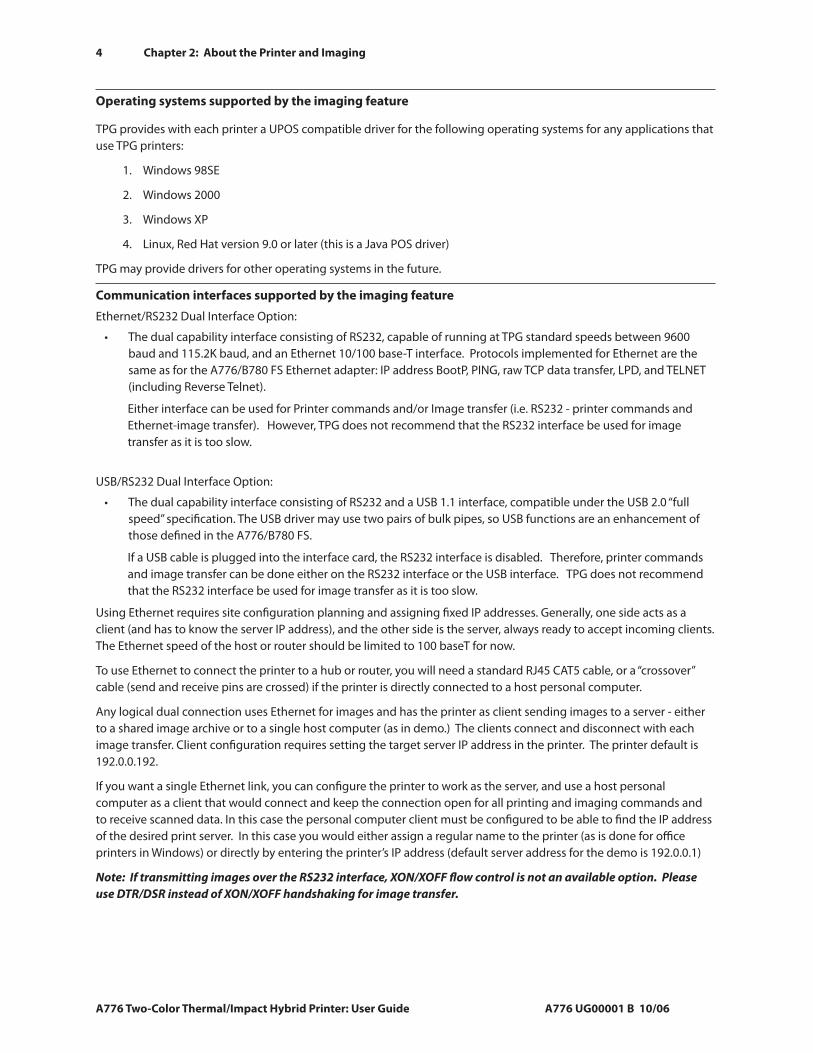
User controls for both A776 printers
The printer and imager have the following controls:
The Paper Feed button advances the receipt paper and allows you to step through the configuration menu items.
The On-line, Paper Status, Error light shows the printer status by shining or flashing.
The slip-in light indicates that a form is inserted properly.
The reset button clears the printer’s memory and resets the printer.
1.
2.
3.
4.
After the printer is turned on or reset, it beeps once to show that it has completed its startup and self-test routine.
If the printer keeps beeping, something is wrong with the printer. Please call your service representative.
Receipt Cover
Reset Button
Front Cover
Receipt
Slip or check
On-line,
Paper status,
Error Light
(green)
Paper Feed Button
Slip in Light (green)
1
3
2
4
6 Chapter 2: About the Printer and Imaging
A776 Two-Color Thermal/Impact Hybrid Printer: User Guide A776 UG00001 B 10/06
Printer Configurations
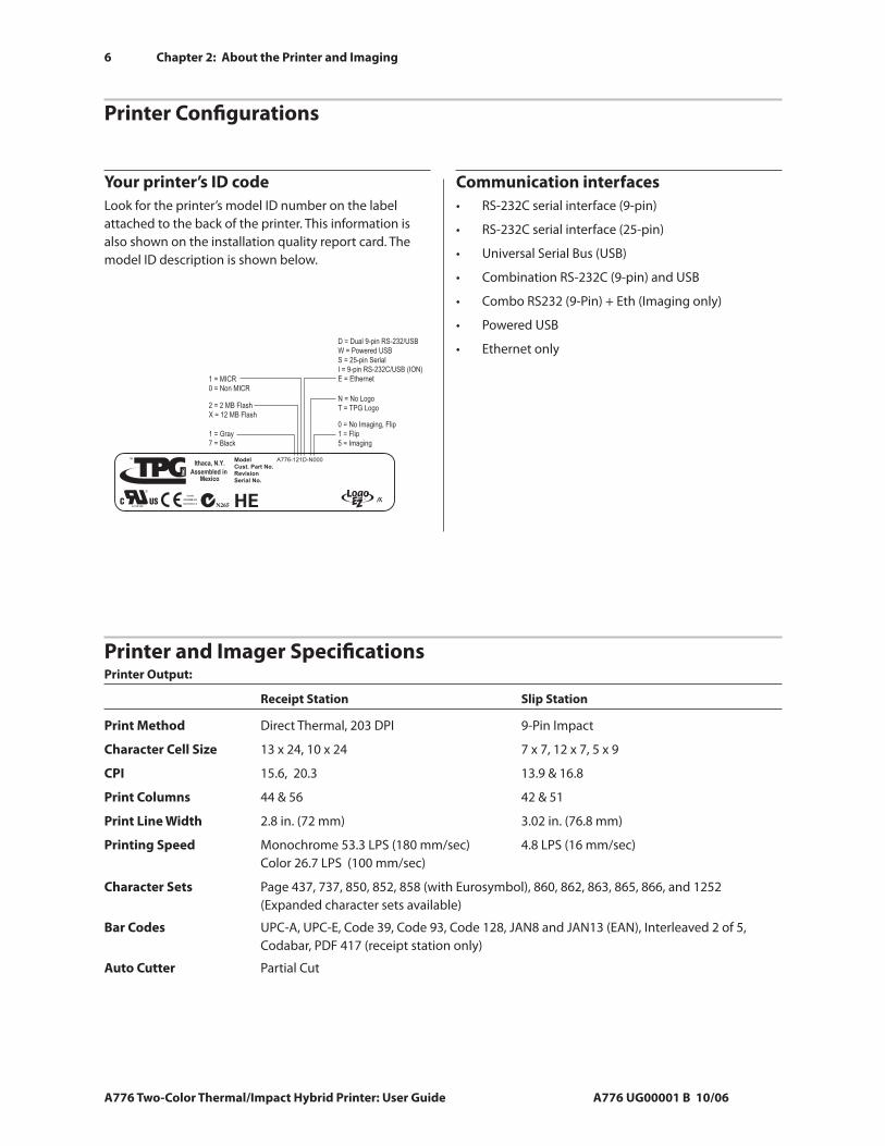
Your printer’s ID codeLook for the printer’s model ID number on the label attached to the back of the printer. This information is also shown on the installation quality report card. The model ID description is shown below.
Communication interfacesRS-232C serial interface (9-pin)
RS-232C serial interface (25-pin)
Universal Serial Bus (USB)
Combination RS-232C (9-pin) and USB
Combo RS232 (9-Pin) + Eth (Imaging only)
Powered USB
Ethernet only
•
•
•
•
•
•
•
ModelCust. Part No.RevisionSerial No.
A776-121D-N000
1 = Gray
7 = Black
2 = 2 MB Flash
X = 12 MB Flash
1 = MICR
0 = Non MICR
D = Dual 9-pin RS-232/USB
W = Powered USB
S = 25-pin Serial
I = 9-pin RS-232C/USB (ION)
E = Ethernet
N = No Logo
T = TPG Logo
0 = No Imaging, Flip
1 = Flip
5 = Imaging
Ithaca, N.Y.
Assembled in Mexico
Canada
ICES/NMB-003
Class/Classe A
Serial Label Callout.eps
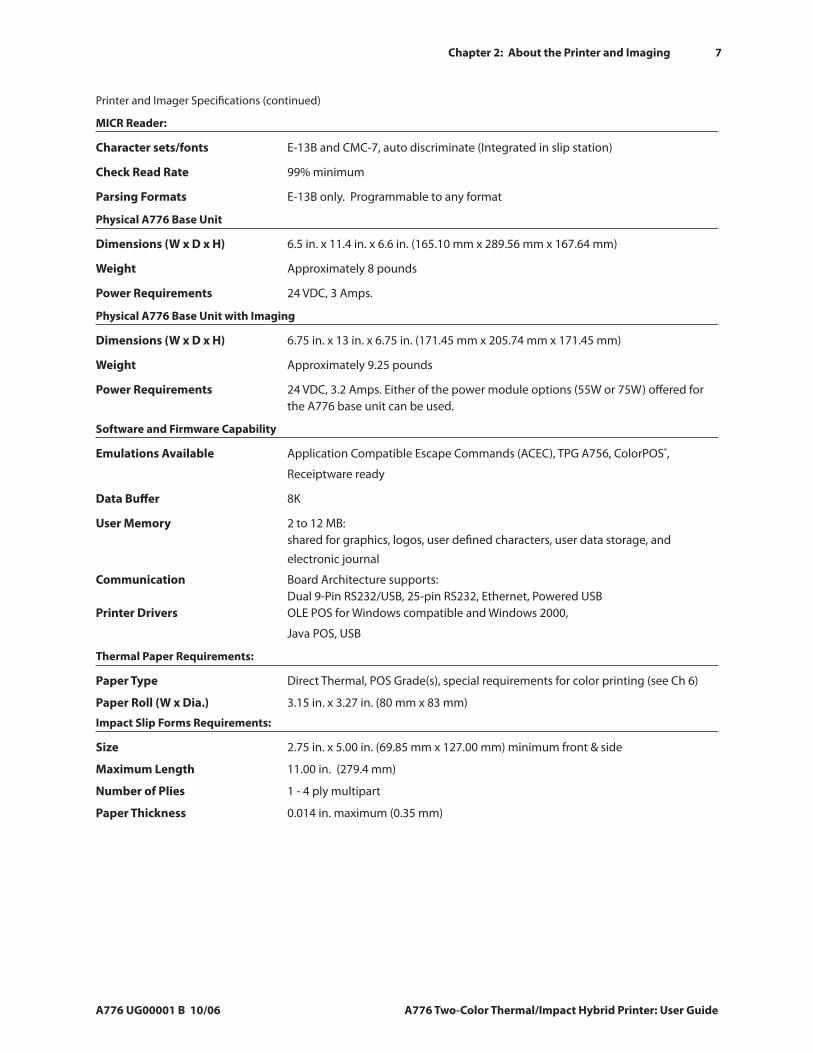
Printer and Imager SpecificationsPrinter Output:
Receipt Station Slip Station
Print Method Direct Thermal, 203 DPI 9-Pin Impact
Character Cell Size 13 x 24, 10 x 24 7 x 7, 12 x 7, 5 x 9
CPI 15.6, 20.3 13.9 & 16.8
Print Columns 44 & 56 42 & 51
Print Line Width 2.8 in. (72 mm) 3.02 in. (76.8 mm)
Printing Speed Monochrome 53.3 LPS (180 mm/sec) 4.8 LPS (16 mm/sec) Color 26.7 LPS (100 mm/sec)
Character Sets Page 437, 737, 850, 852, 858 (with Eurosymbol), 860, 862, 863, 865, 866, and 1252 (Expanded character sets available)
Bar Codes UPC-A, UPC-E, Code 39, Code 93, Code 128, JAN8 and JAN13 (EAN), Interleaved 2 of 5, Codabar, PDF 417 (receipt station only)
Auto Cutter Partial Cut
Chapter 2: About the Printer and Imaging
A776 UG00001 B 10/06 A776 Two-Color Thermal/Impact Hybrid Printer: User Guide
7
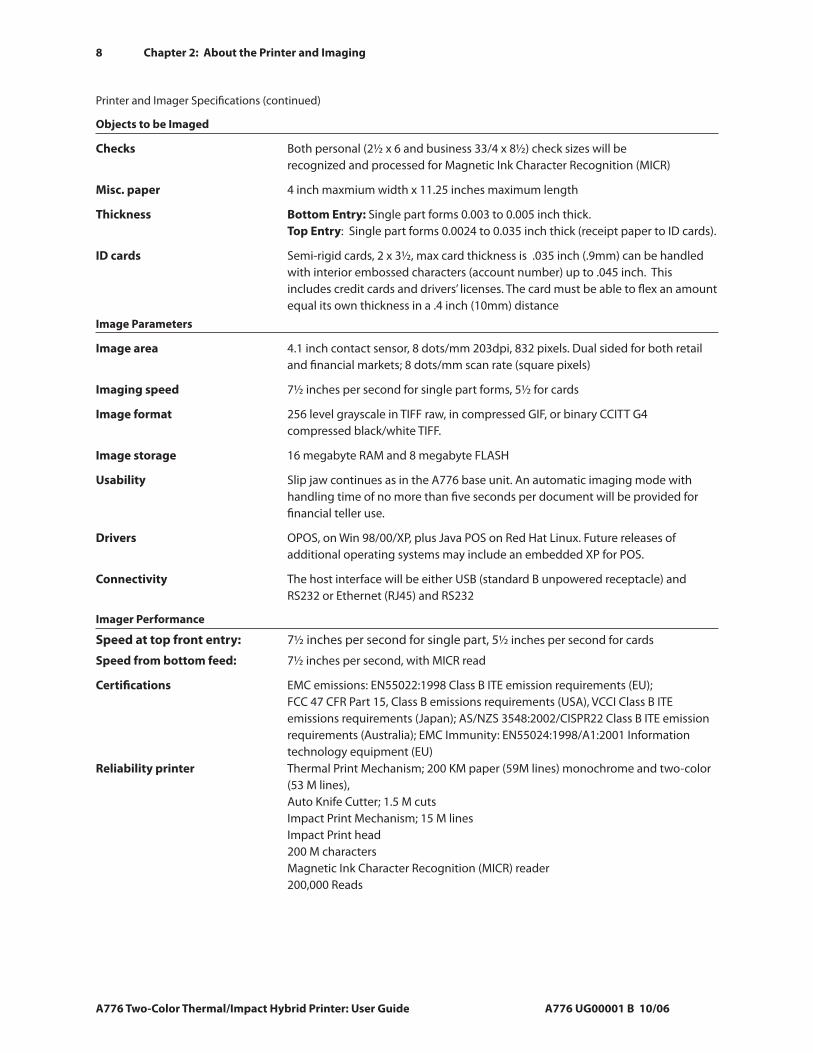
Printer and Imager Specifications (continued)
MICR Reader:
Character sets/fonts E-13B and CMC-7, auto discriminate (Integrated in slip station)
Check Read Rate 99% minimum
Parsing Formats E-13B only. Programmable to any format
Physical A776 Base Unit
Dimensions (W x D x H) 6.5 in. x 11.4 in. x 6.6 in. (165.10 mm x 289.56 mm x 167.64 mm)
Weight Approximately 8 pounds
Power Requirements 24 VDC, 3 Amps.
Physical A776 Base Unit with Imaging
Dimensions (W x D x H) 6.75 in. x 13 in. x 6.75 in. (171.45 mm x 205.74 mm x 171.45 mm)
Weight Approximately 9.25 pounds
Power Requirements 24 VDC, 3.2 Amps. Either of the power module options (55W or 75W) offered for the A776 base unit can be used.
Software and Firmware Capability
Emulations Available Application Compatible Escape Commands (ACEC), TPG A756, ColorPOS®,
Receiptware ready
Data Buffer 8K
User Memory 2 to 12 MB: shared for graphics, logos, user defined characters, user data storage, and
electronic journal
Communication Board Architecture supports: Dual 9-Pin RS232/USB, 25-pin RS232, Ethernet, Powered USB Printer Drivers OLE POS for Windows compatible and Windows 2000,
Java POS, USB
Thermal Paper Requirements:
Paper Type Direct Thermal, POS Grade(s), special requirements for color printing (see Ch 6)
Paper Roll (W x Dia.) 3.15 in. x 3.27 in. (80 mm x 83 mm)
Impact Slip Forms Requirements:
Size 2.75 in. x 5.00 in. (69.85 mm x 127.00 mm) minimum front & side
Maximum Length 11.00 in. (279.4 mm)
Number of Plies 1 - 4 ply multipart
Paper Thickness 0.014 in. maximum (0.35 mm)
8 Chapter 2: About the Printer and Imaging
A776 Two-Color Thermal/Impact Hybrid Printer: User Guide A776 UG00001 B 10/06
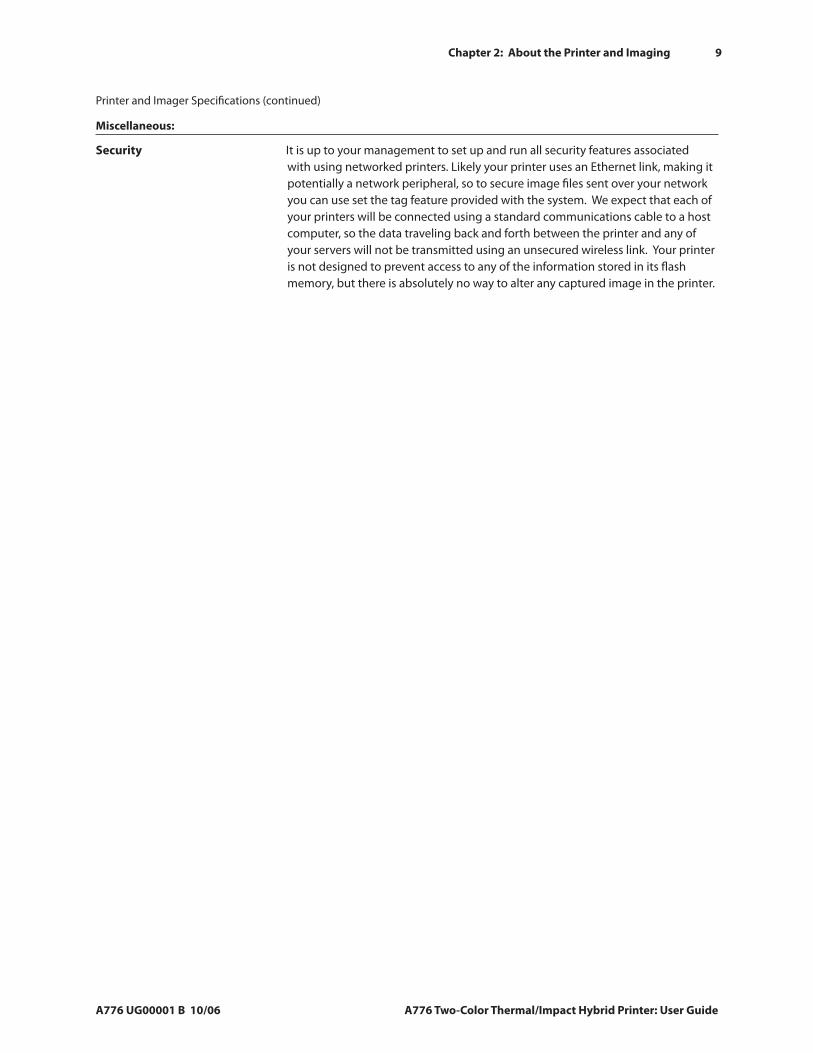
Printer and Imager Specifications (continued)
Objects to be Imaged
Checks Both personal (2½ x 6 and business 33/4 x 8½) check sizes will be recognized and processed for Magnetic Ink Character Recognition (MICR)
Misc. paper 4 inch maxmium width x 11.25 inches maximum length
Thickness Bottom Entry: Single part forms 0.003 to 0.005 inch thick. Top Entry: Single part forms 0.0024 to 0.035 inch thick (receipt paper to ID cards).
ID cards Semi-rigid cards, 2 x 3½, max card thickness is .035 inch (.9mm) can be handled with interior embossed characters (account number) up to .045 inch. This includes credit cards and drivers’ licenses. The card must be able to flex an amount equal its own thickness in a .4 inch (10mm) distance
Image Parameters
Image area 4.1 inch contact sensor, 8 dots/mm 203dpi, 832 pixels. Dual sided for both retail and financial markets; 8 dots/mm scan rate (square pixels)
Imaging speed 7½ inches per second for single part forms, 5½ for cards
Image format 256 level grayscale in TIFF raw, in compressed GIF, or binary CCITT G4 compressed black/white TIFF.
Image storage 16 megabyte RAM and 8 megabyte FLASH
Usability Slip jaw continues as in the A776 base unit. An automatic imaging mode with handling time of no more than five seconds per document will be provided for financial teller use.
Drivers OPOS, on Win 98/00/XP, plus Java POS on Red Hat Linux. Future releases of additional operating systems may include an embedded XP for POS.
Connectivity The host interface will be either USB (standard B unpowered receptacle) and RS232 or Ethernet (RJ45) and RS232
Imager Performance
Speed at top front entry: 7½ inches per second for single part, 5½ inches per second for cards
Speed from bottom feed: 7½ inches per second, with MICR read
Certifications EMC emissions: EN55022:1998 Class B ITE emission requirements (EU); FCC 47 CFR Part 15, Class B emissions requirements (USA), VCCI Class B ITE emissions requirements (Japan); AS/NZS 3548:2002/CISPR22 Class B ITE emission requirements (Australia); EMC Immunity: EN55024:1998/A1:2001 Information technology equipment (EU)
Reliability printer Thermal Print Mechanism; 200 KM paper (59M lines) monochrome and two-color (53 M lines), Auto Knife Cutter; 1.5 M cuts Impact Print Mechanism; 15 M lines Impact Print head 200 M characters Magnetic Ink Character Recognition (MICR) reader 200,000 Reads
Chapter 2: About the Printer and Imaging
A776 UG00001 B 10/06 A776 Two-Color Thermal/Impact Hybrid Printer: User Guide
9
Printer and Imager Specifications (continued)
Miscellaneous:
Security It is up to your management to set up and run all security features associated with using networked printers. Likely your printer uses an Ethernet link, making it potentially a network peripheral, so to secure image files sent over your network you can use set the tag feature provided with the system. We expect that each of your printers will be connected using a standard communications cable to a host computer, so the data traveling back and forth between the printer and any of your servers will not be transmitted using an unsecured wireless link. Your printer is not designed to prevent access to any of the information stored in its flash memory, but there is absolutely no way to alter any captured image in the printer.
10 Chapter 3: Settng up the Printer
A776 Two-Color Thermal/Impact Hybrid Printer: User Guide A776 UG00001 B 10/06
6.5"
11.4"
6.6"
A776 Dim left side.eps
Chapter 3: Setting up the Printer
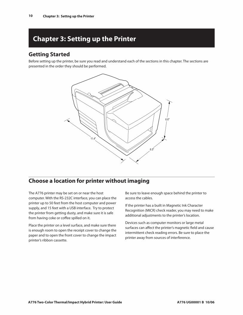
Getting Started Before setting up the printer, be sure you read and understand each of the sections in this chapter. The sections are presented in the order they should be performed.
Choose a location for printer without imaging
Be sure to leave enough space behind the printer to access the cables.
If the printer has a built in Magnetic Ink Character Recognition (MICR) check reader, you may need to make additional adjustments to the printer’s location.
Devices such as computer monitors or large metal surfaces can affect the printer’s magnetic field and cause intermittent check reading errors. Be sure to place the printer away from sources of interference.
The A776 printer may be set on or near the host computer. With the RS-232C interface, you can place the printer up to 50 feet from the host computer and power supply, and 15 feet with a USB interface. Try to protect the printer from getting dusty, and make sure it is safe from having coke or coffee spilled on it.
Place the printer on a level surface, and make sure there is enough room to open the receipt cover to change the paper and to open the front cover to change the impact printer’s ribbon cassette.
Chapter 3: Settng up the Printer
A776 UG00001 B 10/06 A776 Two-Color Thermal/Impact Hybrid Printer: User Guide
11
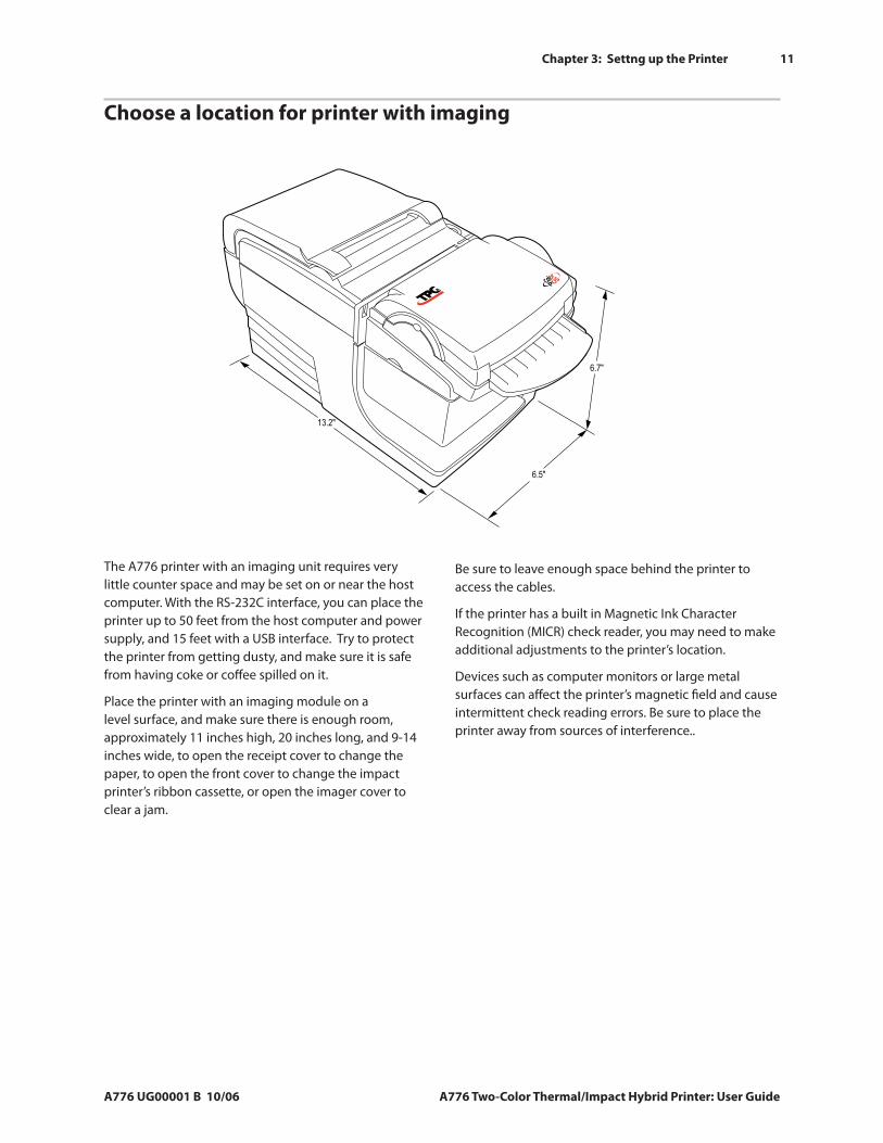
Choose a location for printer with imaging
The A776 printer with an imaging unit requires very little counter space and may be set on or near the host computer. With the RS-232C interface, you can place the printer up to 50 feet from the host computer and power supply, and 15 feet with a USB interface. Try to protect the printer from getting dusty, and make sure it is safe from having coke or coffee spilled on it.
Place the printer with an imaging module on a level surface, and make sure there is enough room, approximately 11 inches high, 20 inches long, and 9-14 inches wide, to open the receipt cover to change the paper, to open the front cover to change the impact printer’s ribbon cassette, or open the imager cover to clear a jam.
Be sure to leave enough space behind the printer to access the cables.
If the printer has a built in Magnetic Ink Character Recognition (MICR) check reader, you may need to make additional adjustments to the printer’s location.
Devices such as computer monitors or large metal surfaces can affect the printer’s magnetic field and cause intermittent check reading errors. Be sure to place the printer away from sources of interference..
6.5"
13.2"
6.7"
12 Chapter 3: Settng up the Printer
A776 Two-Color Thermal/Impact Hybrid Printer: User Guide A776 UG00001 B 10/06
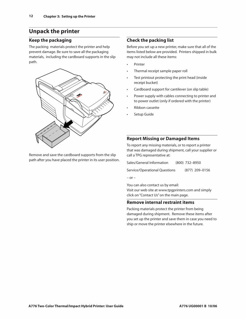
Keep the packagingThe packing materials protect the printer and help prevent damage. Be sure to save all the packaging materials, including the cardboard supports in the slip path.
Remove and save the cardboard supports from the slip path after you have placed the printer in its user position.
Unpack the printer
Report Missing or Damaged Items To report any missing materials, or to report a printer that was damaged during shipment, call your supplier or call a TPG representative at:
Sales/General Information (800) 732–8950
Service/Operational Questions (877) 209–0156
– or –
You can also contact us by email: Visit our web site at www.tpgprinters.com and simply click on “Contact Us” on the main page.
Remove internal restraint itemsPacking materials protect the printer from being damaged during shipment. Remove these items after you set up the printer and save them in case you need to ship or move the printer elsewhere in the future.
Check the packing listBefore you set up a new printer, make sure that all of the items listed below are provided. Printers shipped in bulk may not include all these items:
Printer
Thermal receipt sample paper roll
Test printout protecting the print head (inside receipt bucket)
Cardboard support for cantilever (on slip table)
Power supply with cables connecting to printer and to power outlet (only if ordered with the printer)
Ribbon cassette
Setup Guide
•
•
•
•
•
•
•
A776 Unpack left side.eps
Chapter 3: Settng up the Printer
A776 UG00001 B 10/06 A776 Two-Color Thermal/Impact Hybrid Printer: User Guide
13
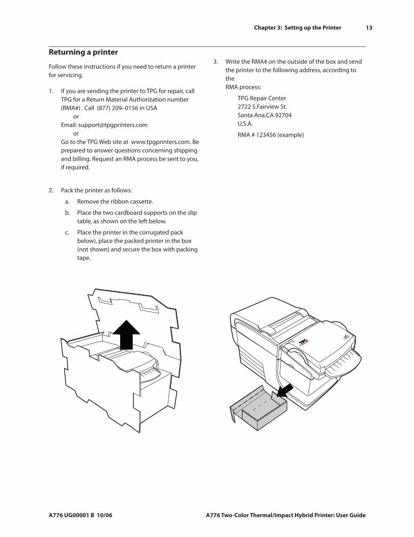
Returning a printer
Follow these instructions if you need to return a printer for servicing.
If you are sending the printer to TPG for repair, call TPG for a Return Material Authorization number (RMA#) . Call (877) 209–0156 in USA or Email: [email protected] or Go to the TPG Web site at www.tpgprinters.com. Be prepared to answer questions concerning shipping and billing. Request an RMA process be sent to you, if required.
1.
Pack the printer as follows:
Remove the ribbon cassette.
Place the two cardboard supports on the slip table, as shown on the left below.
Place the printer in the corrugated pack below), place the packed printer in the box (not shown) and secure the box with packing tape.
2.
a.
b.
c.
Write the RMA# on the outside of the box and send the printer to the following address, according to the RMA process:
TPG Repair Center 2722 S.Fairview St. Santa Ana,CA 92704 U.S.A.
RMA # 123456 (example)
3.
A776 Unpack left side.eps
14 Chapter 3: Settng up the Printer
A776 Two-Color Thermal/Impact Hybrid Printer: User Guide A776 UG00001 B 10/06
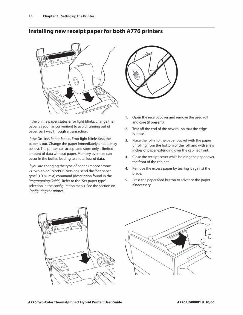
If the online paper status error light blinks, change the paper as soon as convenient to avoid running out of paper part way through a transaction.
If the On-line, Paper Status, Error light blinks fast, the paper is out. Change the paper immediately or data may be lost. The printer can accept and store only a limited amount of data without paper. Memory overload can occur in the buffer, leading to a total loss of data.
If you are changing the type of paper (monochrome vs. two-color ColorPOS® version) send the “Set paper type” (1D 81 m n) command (description found in the Programming Guide). Refer to the “Set paper type” selection in the configuration menu. See the section on Configuring the printer.
Open the receipt cover and remove the used roll and core (if present).
Tear off the end of the new roll so that the edge is loose.
Place the roll into the paper bucket with the paper unrolling from the bottom of the roll, and with a few inches of paper extending over the cabinet front.
Close the receipt cover while holding the paper over the front of the cabinet.
Remove the excess paper by tearing it against the blade.
Press the paper feed button to advance the paper if necessary.
1.
2.
3.
4.
4.
5.
Installing new receipt paper for both A776 printers
A776 Install Paper 1.eps
Install paper NO.eps
A776 Install paper 2.eps
A776 Install Paper 3.eps
Chapter 3: Settng up the Printer
A776 UG00001 B 10/06 A776 Two-Color Thermal/Impact Hybrid Printer: User Guide
15
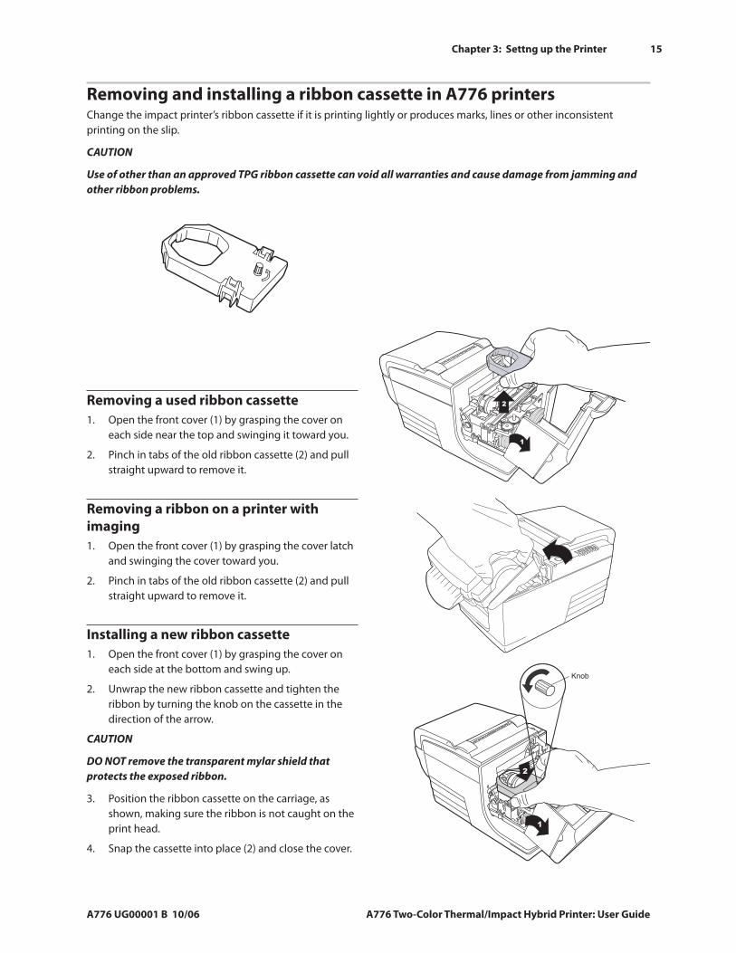
Removing and installing a ribbon cassette in A776 printersChange the impact printer’s ribbon cassette if it is printing lightly or produces marks, lines or other inconsistent printing on the slip.
CAUTION
Use of other than an approved TPG ribbon cassette can void all warranties and cause damage from jamming and other ribbon problems.
Removing a used ribbon cassetteOpen the front cover (1) by grasping the cover on each side near the top and swinging it toward you.
Pinch in tabs of the old ribbon cassette (2) and pull straight upward to remove it.
1.
2.
Installing a new ribbon cassetteOpen the front cover (1) by grasping the cover on each side at the bottom and swing up.
Unwrap the new ribbon cassette and tighten the ribbon by turning the knob on the cassette in the direction of the arrow.
CAUTION
DO NOT remove the transparent mylar shield that protects the exposed ribbon.
Position the ribbon cassette on the carriage, as shown, making sure the ribbon is not caught on the print head.
Snap the cassette into place (2) and close the cover.
1.
2.
3.
4.
A776 Lift Ribbon.eps
2
1
A776 Replace Ribbon.eps
Knob
2
1
Ribbon Alone.eps
Removing a ribbon on a printer with imaging
Open the front cover (1) by grasping the cover latch and swinging the cover toward you.
Pinch in tabs of the old ribbon cassette (2) and pull straight upward to remove it.
1.
2.
16 Chapter 3: Settng up the Printer
A776 Two-Color Thermal/Impact Hybrid Printer: User Guide A776 UG00001 B 10/06
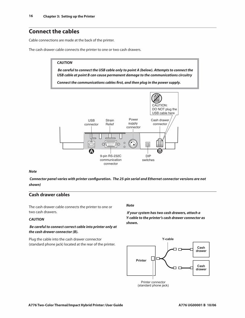
Connect the cablesCable connections are made at the back of the printer.
The cash drawer cable connects the printer to one or two cash drawers.
CAUTION
Be careful to connect the USB cable only to point A (below). Attempts to connect the USB cable at point B can cause permanent damage to the communications circuitry
Connect the communications cables first, and then plug in the power supply.
Note
If your system has two cash drawers, attach a Y-cable to the printer’s cash drawer connector as shown.
�������
�������
����������
����������
��������������������������������������
Note
Connector panel varies with printer configuration. The 25-pin serial and Ethernet connector versions are not shown)
The cash drawer cable connects the printer to one or two cash drawers.
CAUTION
Be careful to connect correct cable into printer only at the cash drawer connector (B).
Plug the cable into the cash drawer connector (standard phone jack) located at the rear of the printer.
Cash drawer cables
StrainRelief
DIPswitches
9-pin RS-232Ccommunication
connector
CAUTION:DO NOT plug theUSB cable here
Cash drawerconnector
USBconnector
Powersupply
connector
Chapter 3: Settng up the Printer
A776 UG00001 B 10/06 A776 Two-Color Thermal/Impact Hybrid Printer: User Guide
17
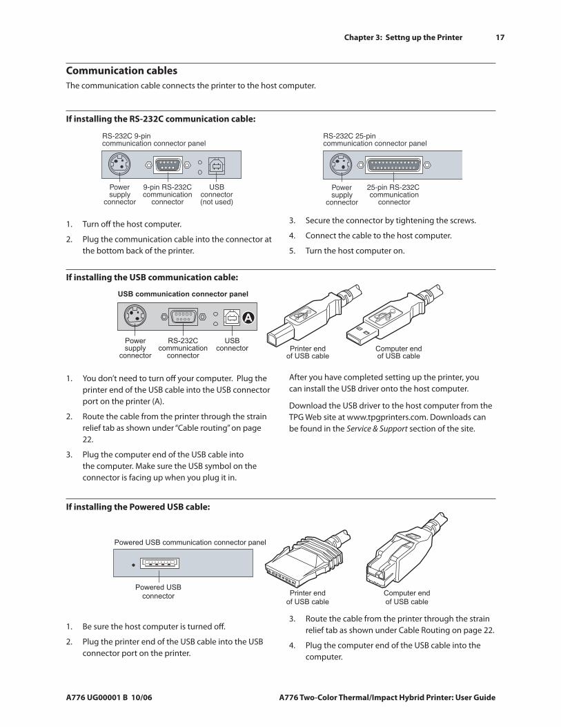
Communication cablesThe communication cable connects the printer to the host computer.
If installing the RS-232C communication cable:
Secure the connector by tightening the screws.
Connect the cable to the host computer.
Turn the host computer on.
3.
4.
5.
Turn off the host computer.
Plug the communication cable into the connector at the bottom back of the printer.
1.
2.
If installing the USB communication cable:
You don’t need to turn off your computer. Plug the printer end of the USB cable into the USB connector port on the printer (A).
Route the cable from the printer through the strain relief tab as shown under “Cable routing” on page 22.
Plug the computer end of the USB cable into the computer. Make sure the USB symbol on the connector is facing up when you plug it in.
1.
2.
3.
After you have completed setting up the printer, you can install the USB driver onto the host computer.
Download the USB driver to the host computer from the TPG Web site at www.tpgprinters.com. Downloads can be found in the Service & Support section of the site.
If installing the Powered USB cable:
Be sure the host computer is turned off.
Plug the printer end of the USB cable into the USB connector port on the printer.
1.
2.
Route the cable from the printer through the strain relief tab as shown under Cable Routing on page 22.
Plug the computer end of the USB cable into the computer.
3.
4.
Powered USB communication connector panel
Powered USB
connector Printer end
of USB cable
Computer end
of USB cable
18 Chapter 3: Settng up the Printer
A776 Two-Color Thermal/Impact Hybrid Printer: User Guide A776 UG00001 B 10/06
Ethernet communication connector panel
Ethernetconnector
Powersupply
connector
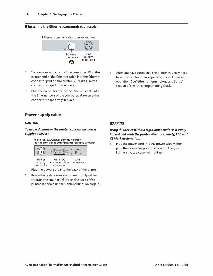
If installing the Ethernet communication cable:
You don’t need to turn off the computer. Plug the printer end of the Ethernet cable into the Ethernet connector port on the printer (A). Make sure the connector snaps firmly in place.
Plug the computer end of the Ethernet cable into the Ethernet port of the computer. Make sure the connector snaps firmly in place.
1.
2.
After you have connected the printer, you may need to set the printer internal parameters for Ethernet operation. See “Ethernet Terminology and Setup” section of the A776 Programming Guide.
3.
Power supply cable
Plug the power cord into the back of the printer.
Route the cash drawer and power supply cables through the strain relief tab on the back of the printer as shown under “Cable routing” on page 22.
1.
2.
WARNING
Using this device without a grounded outlet is a safety hazard and voids the printer Warranty, Safety, FCC and CE Mark designation.
Plug the power cord into the power supply, then plug the power supply into an outlet. The green light on the top cover will light up.
3.
CAUTION
To avoid damage to the printer, connect the power supply cable last.
Chapter 3: Settng up the Printer
A776 UG00001 B 10/06 A776 Two-Color Thermal/Impact Hybrid Printer: User Guide
19
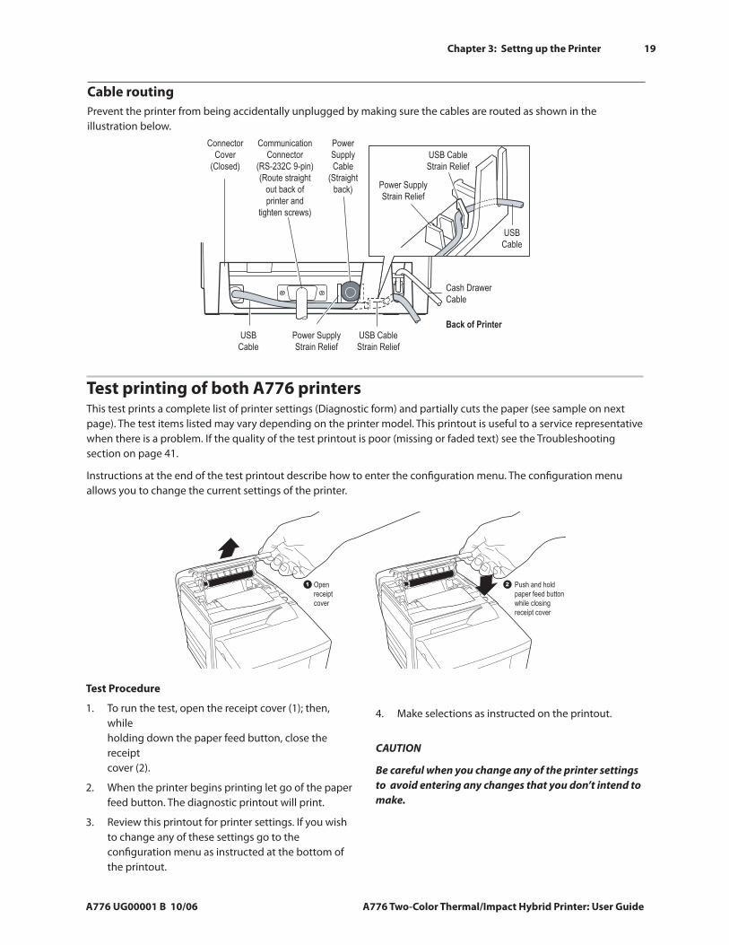
Cable routingPrevent the printer from being accidentally unplugged by making sure the cables are routed as shown in the illustration below.
Test printing of both A776 printers This test prints a complete list of printer settings (Diagnostic form) and partially cuts the paper (see sample on next page). The test items listed may vary depending on the printer model. This printout is useful to a service representative when there is a problem. If the quality of the test printout is poor (missing or faded text) see the Troubleshooting section on page 41.
Instructions at the end of the test printout describe how to enter the configuration menu. The configuration menu allows you to change the current settings of the printer.
Test Procedure
To run the test, open the receipt cover (1); then, while holding down the paper feed button, close the receipt cover (2).
When the printer begins printing let go of the paper feed button. The diagnostic printout will print.
Review this printout for printer settings. If you wish to change any of these settings go to the configuration menu as instructed at the bottom of the printout.
1.
2.
3.
Make selections as instructed on the printout.
CAUTION
Be careful when you change any of the printer settings to avoid entering any changes that you don’t intend to make.
4.
21 Openreceipt cover
Push and holdpaper feed buttonwhile closingreceipt cover
A776 Test Printer.eps
ConnectorCover
(Closed)
CommunicationConnector
(RS-232C 9-pin)(Route straight
out back ofprinter and
tighten screws)
PowerSupplyCable
(Straightback)
USB CableStrain Relief
USBCable
Cash DrawerCable
Back of PrinterUSB CableStrain Relief
Power SupplyStrain Relief
USBCable
Power SupplyStrain Relief
A776 Strain Releif.eps
20 Chapter 3: Settng up the Printer
A776 Two-Color Thermal/Impact Hybrid Printer: User Guide A776 UG00001 B 10/06
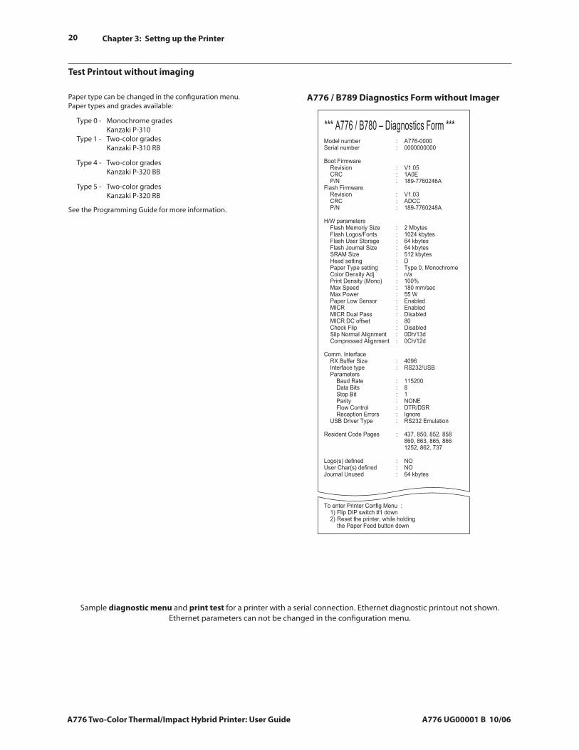
Sample diagnostic menu and print test for a printer with a serial connection. Ethernet diagnostic printout not shown. Ethernet parameters can not be changed in the configuration menu.
Paper type can be changed in the configuration menu. Paper types and grades available:
Type 0 - Monochrome grades Kanzaki P-310 Type 1 - Two-color grades Kanzaki P-310 RB
Type 4 - Two-color grades Kanzaki P-320 BB
Type 5 - Two-color grades Kanzaki P-320 RB
See the Programming Guide for more information.
Test Printout without imaging
A776 / B789 Diagnostics Form without Imager
*** A776 / B780 – Diagnostics Form ***Model number : A776-0000Serial number : 0000000000
Boot Firmware Revision : V1.05 CRC : 1A0E P/N : 189-7760246AFlash Firmware Revision : V1.03 CRC : ADCC P/N : 189-7760248A
H/W parameters Flash Memoriy Size : 2 Mbytes Flash Logos/Fonts : 1024 kbytes Flash User Storage : 64 kbytes Flash Journal Size : 64 kbytes SRAM Size : 512 kbytes Head setting : D Paper Type setting : Type 0, Monochrome Color Density Adj : n/a Print Density (Mono) : 100% Max Speed : 180 mm/sec Max Power : 55 W Paper Low Sensor : Enabled MICR : Enabled MICR Dual Pass : Disabled MICR DC offset : 80 Check Flip : Disabled Slip Normal Alignment : 0Dh/13d Compressed Alignment : 0Ch/12d
Comm. Interface RX Buffer Size : 4096 Interface type : RS232/USB Parameters Baud Rate : 115200 Data Bits : 8 Stop Bit : 1 Parity : NONE Flow Control : DTR/DSR Reception Errors : Ignore USB Driver Type : RS232 Emulation
Resident Code Pages : 437, 850, 852. 858 860, 863, 865, 866 1252, 862, 737
Logo(s) defined : NOUser Char(s) defined : NOJournal Unused : 64 kbytes
To enter Printer Config Menu : 1) Flip DIP switch #1 down 2) Reset the printer, while holding the Paper Feed button down
Chapter 3: Settng up the Printer
A776 UG00001 B 10/06 A776 Two-Color Thermal/Impact Hybrid Printer: User Guide
21
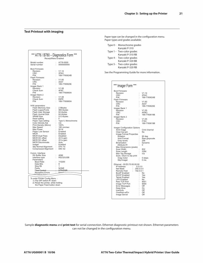
Sample diagnostic menu and print test for serial connection. Ethernet diagnostic printout not shown. Ethernet parameters can not be changed in the configuration menu.
Paper type can be changed in the configuration menu. Paper types and grades available:
Type 0 - Monochrome grades Kanzaki P-310 Type 1 - Two-color grades Kanzaki P-310 RB Type 4 - Two-color grades Kanzaki P-320 BB Type 5 - Two-color grades Kanzaki P-320 RB
See the Programming Guide for more information.
Test Printout with imaging
*** Imager Form ***Boot Firmware Revision : V1.14 CRC : 2FAO P/N : 189-7760624BFlash Firmware Revision : V1.60 CRC : A037 P/N : 189-7760620EImager Bank 1 Revision : V1.05 CRC : AFBO P/N : 189-7760619BImager Bank 2 Revision : V1.05 CRC : F763 P/N : 189-7760619B
Imager Configuration Options Xmit image : Cmd channel Clear top jam : No Image Format Properties Rotation : 90 deg Xmit Format : Raw grayscale Gray levels : 256 Binarization : Dynamic Attribute #1 : 0 Max Dimensions (pixels) Scan Width : 832 Scan Length : 2284 Max Tag Storage : n/a Scan, return to slip print Imag motor : 0 steps Slip:Imager : 0 ms.
Ethernet - 00:E0:70:00:00:00 IP Address : 0.0.0.0 Net Mask : 255.0.0.0 Remote Host : 192.0.0.1 BootP Enabled : No DHCP Enabled : Yes Telnet Enabled : Yes LPD Enabled : No Raw TCP Port : 9001 Image TCP Port : 9000 Error Messages : Off Keep Alive : On Inactivity : Off Overflow w/Err : Off Image Server : Off
*** A776 / B780 – Diagnostics Form ***ReceiptWare Enabled
To enter Printer Config Menu : 1) Flip DIP switch #1 down 2) Reset the printer, while holding the Paper Feed button down
Model number : A776-0000Serial number : 0000000000
Boot Firmware Revision : V1.14 CRC : 2FAO P/N : 189-7760624BFlash Firmware Revision : V1.60 CRC : A037 P/N : 189-7760620EImager Bank 1 Revision : V1.08 Check Sum : 4F9C P/N : 189-7760660AImager Bank 2 Revision : V1.08 Check Sum : E6FE P/N : 189-7760660A
H/W parameters Flash Memoriy Size : 2 Mbytes Flash Logos/Fonts : 960 kbytes Flash User Storage : 64 kbytes Flash Journal Size : 64 kbytes SRAM Size : 512 kbytes Head setting : F Paper Type setting : Type 0, Monochrome Color Density Adj : n/a Print Density (Mono) : 100% Max Speed : 180 mm/sec Max Power : 55 W Paper Low Sensor : Enabled MICR : Enabled MICR Dual Pass : Disabled MICR DC offset : 22 hi gain MICR DC offset : 22 lo gain MICR Discriminate : Auto Imager : Enabled Slip Normal Alignment : 07h/ 7d Compressed Alignment : 04h/ 4d
Comm. Interface RX Buffer Size : 4096 Interface type : RS232/USB Parameters Baud Rate : 115200 Data Bits : 8 Stop Bit : 1 Parity : NONE Flow Control : DTR/DSR Reception Errors : Ignore USB Driver Type : RS232 Emulation
22 Chapter 3: Settng up the Printer
A776 Two-Color Thermal/Impact Hybrid Printer: User Guide A776 UG00001 B 10/06
Printer and imager configurations
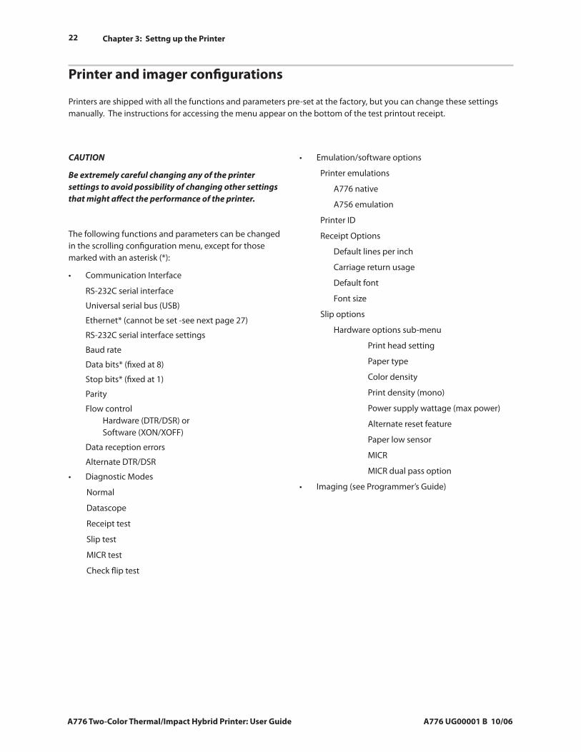
Printers are shipped with all the functions and parameters pre-set at the factory, but you can change these settings manually. The instructions for accessing the menu appear on the bottom of the test printout receipt.
CAUTION
Be extremely careful changing any of the printer settings to avoid possibility of changing other settings that might affect the performance of the printer.
The following functions and parameters can be changed in the scrolling configuration menu, except for those marked with an asterisk (*):
Communication Interface
RS-232C serial interface
Universal serial bus (USB)
Ethernet* (cannot be set -see next page 27)
RS-232C serial interface settings
Baud rate
Data bits* (fixed at 8)
Stop bits* (fixed at 1)
Parity
Flow control Hardware (DTR/DSR) or Software (XON/XOFF)
Data reception errors
Alternate DTR/DSR
Diagnostic Modes
Normal
Datascope
Receipt test
Slip test
MICR test
Check flip test
•
•
Emulation/software options
Printer emulations
A776 native
A756 emulation
Printer ID
Receipt Options
Default lines per inch
Carriage return usage
Default font
Font size
Slip options
Hardware options sub-menu
Print head setting
Paper type
Color density
Print density (mono)
Power supply wattage (max power)
Alternate reset feature
Paper low sensor
MICR
MICR dual pass option
Imaging (see Programmer’s Guide)
•
•
Chapter 3: Settng up the Printer
A776 UG00001 B 10/06 A776 Two-Color Thermal/Impact Hybrid Printer: User Guide
23
Configuring the printerCAUTION
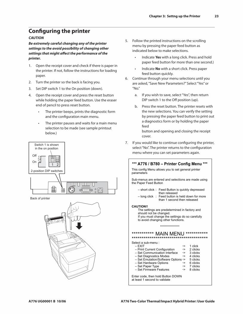
*** A776 / B780 – Printer Config Menu ***This config Menu allows you to set general printer parameters
Sub-menus are entered and selections are made using the Paper Feed Button
– short click : Feed Button is quickly depressed then released – long click : Feed button is held down for more than 1 second then released
CAUTION!! The settings are predetermined in factory and should not be changed. If you must change the settings do so carefully to avoid changing other functions.
****************
****************************************************************************Select a sub-menu : – EXIT -> 1 click – Print Current Configuration -> 2 clicks – Set Communication Interface -> 3 clicks – Set Diagnostics Modes -> 4 clicks – Set Emulation/Software Options -> 5 clicks – Set Hardware Options -> 6 clicks – Set Paper Type -> 7 clicks – Set Firmware Features -> 8 clicks
Enter code, then hold Button DOWNat least 1 second to validate
MAIN MENU
Back of printer
On
Switch 1 is shown
in the on position
Off
2-position DIP switches
1 2
Be extremely careful changing any of the printer settings to the avoid possibility of changing other settings that might affect the performance of the printer.
Open the receipt cover and check if there is paper in the printer. If not, follow the instructions for loading paper.
Turn the printer so the back is facing you.
Set DIP switch 1 to the On position (down).
Open the receipt cover and press the reset button while holding the paper feed button. Use the eraser end of pencil to press reset button.
The printer beeps, prints the diagnostic form and the configuration main menu.
The printer pauses and waits for a main menu selection to be made (see sample printout below.)
1.
2.
3.
4.
•
•
Follow the printed instructions on the scrolling menu by pressing the paper feed button as indicated below to make selections.
Indicate Yes with a long click. Press and hold paper feed button for more than one second.)
Indicate No with a short click. Press paper feed button quickly.
5.
•
•
Continue through your menu selections until you are asked, “Save New Parameters?” Select “Yes” or “No.”
If you wish to save, select “Yes”, then return DIP switch 1 to the Off position (up).
Press the reset button. The printer resets with the new selections. You can verify the setting by pressing the paper feed button to print out a diagnostics form or by holding the paper feed button and opening and closing the receipt cover.
If you would like to continue configuring the printer, select “No”. The printer returns to the configuration menu where you can set parameters again.
6.
a.
b.
7.
A776 Reset.eps
24 Chapter 3: Settng up the Printer
A776 Two-Color Thermal/Impact Hybrid Printer: User Guide A776 UG00001 B 10/06
Communication interface
To change the communication interface settings (except Ethernet), enter the configuration menu, select “Set Communication Interface” from the main menu and answer “Yes” to “SET INTERFACE TYPE?” printed on the receipt.
CAUTION
Be careful changing any of the printer settings to avoid entering changes you don’t intend to make.
Press the paper feed button as instructed to select the communication interface you want, either RS232C or USB.
RS-232C serial interface settings
To change the RS-232C serial interface settings, enter the configuration menu, select “Set Communication Interface” from the main menu and answer “No” to “SET INTERFACE TYPE?” printed on the receipt. This takes you to the instructions for selecting the RS-232C settings.
Press the paper feed button as instructed on the configuration menu to select the RS-232C settings you want to change:
Baud rate
115200 baud 57600 baud
38400 baud 19200 baud
9600 baud 4800 baud
2400 baud 1200 baud
Number of data bits can not be changed
Stop bits can not be changed
Parity can not be changed
Hardware flow control
Software (XON/XOFF)
Hardware (DTR/DSR)
Data reception errors
Ignore errors
Print “?”
Alternate DTR/DSR
Enabled Disabled
Note
Press the paper feed button for at least one second to validate the selection.
•
•
•
•
•
•
•
To change the diagnostic modes enter the configuration menu, select “Set Diagnostic Modes” from the main menu and select one of the following modes:
Normal: normal operating mode of the printer.
Datascope: The receipt printer prints incoming commands and data in hexadecimal format to help troubleshoot communication problems.
Receipt test: The receipt printer prints two code pages to verify proper printing of the receipt.
Slip test: The slip printer prints two code pages to verify the slip printer is operating properly.
MICR test mode: The receipt printer prints all characters recognized by the MICR (check reader) to verify that the printer is properly reading a check inserted in the slip.
•
•
•
•
•
Diagnostic modes
Chapter 3: Settng up the Printer
A776 UG00001 B 10/06 A776 Two-Color Thermal/Impact Hybrid Printer: User Guide
25
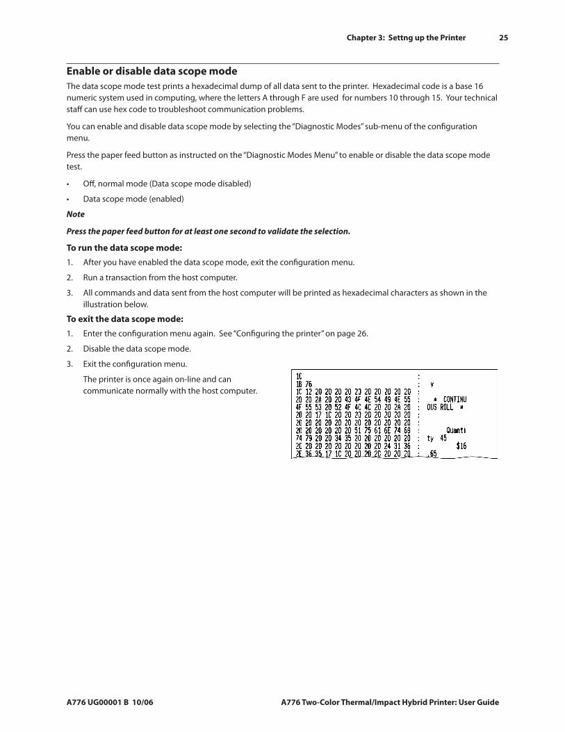
Enable or disable data scope modeThe data scope mode test prints a hexadecimal dump of all data sent to the printer. Hexadecimal code is a base 16 numeric system used in computing, where the letters A through F are used for numbers 10 through 15. Your technical staff can use hex code to troubleshoot communication problems.
You can enable and disable data scope mode by selecting the “Diagnostic Modes” sub-menu of the configuration menu.
Press the paper feed button as instructed on the “Diagnostic Modes Menu” to enable or disable the data scope mode test.
Off, normal mode (Data scope mode disabled)
Data scope mode (enabled)
Note
Press the paper feed button for at least one second to validate the selection.
To run the data scope mode:
After you have enabled the data scope mode, exit the configuration menu.
Run a transaction from the host computer.
All commands and data sent from the host computer will be printed as hexadecimal characters as shown in the illustration below.
To exit the data scope mode:
Enter the configuration menu again. See “Configuring the printer” on page 26.
Disable the data scope mode.
Exit the configuration menu.
The printer is once again on-line and can communicate normally with the host computer.
•
•
1.
2.
3.
1.
2.
3.
26 Chapter 3: Settng up the Printer
A776 Two-Color Thermal/Impact Hybrid Printer: User Guide A776 UG00001 B 10/06
Enable or disable receipt test modeThe receipt test mode verifies proper receipt printing. Receipt test is enabled and disabled by selecting the “Diagnostic Modes” sub-menu of the configuration menu. See “Configuring the printer” on page 26 for instructions on how to enter the configuration menu.
To exit the Receipt test mode:
Enter the configuration menu again. See “Configuring the printer” on page 26
Disable the receipt test mode.
Exit the configuration menu.
The printer is on-line and can again communicate normally with the host computer.
1.
2.
3.
4.
To run the Receipt test mode:
Enable the receipt test mode in the configuration menu.
Exit the configuration menu.
Push the paper feed button. The receipt station prints two code pages and cuts the receipt.
To repeat this test, push the paper feed button again.
1.
2.
3.
4.
Enable or disable slip test mode
The slip test mode verifies proper printing on a slip. Slip test is enabled or disabled by selecting the “Diagnostic Modes” sub-menu of the configuration menu. See “Configuring the printer” on page 26 for instructions on how to enter the configuration menu.
To run the slip test mode:
Enable the slip test mode in the configuration menu.
Exit the configuration menu.
Insert a slip into the slip station.
Push the paper feed button. Two code pages will be printed.
To repeat this test, preform steps 3 and 4 again.
1.
2.
3.
4.
5.
To exit the slip test mode:
Enter the configuration menu again. See “Configuring the printer” on page 26.
Disable the slip test mode.
Exit the configuration menu.
The printer is on-line and can again communicate normally with the host computer.
1.
2.
3.
4.
Enable or disable Magnetic Ink Character Recognition (MICR) test mode
In the MICR test mode the MICR reads the characters on a check, but instead of transmitting the values to the software it prints them out.
You can enable or disable MICR test is enabled or disabled by selecting the “Diagnostic Modes” sub-menu of the configuration menu. See “Configuring the printer” on page 26 for instructions on how to enter the configuration menu.
To run the MICR test mode:
Enable the MICR test mode through the configuration menu. Then exit the configuration menu.
Insert a check into the slip station. See “Verifying and validating checks” on pages 35-36..
After the printer detects the check, the platen closes and the characters are read by the MICR check reader. The decoded data is printed as characters on receipt paper. The platen then opens, and the test is re-started.
The printed characters should match the characters on the check. If the MICR check reader misreads a character, it will print a question mark (“?”). If the reader can’t read any of the characters, “NO MICR CHARACTERS” appears.
1.
2.
3.
4.
To exit the MICR test mode:
Enter the configuration menu again.
Disable the MICR test mode.
Exit the configuration menu.
The printer returns to normal mode and can again communicate with the host computer.
1.
2.
3.
4.
Chapter 3: Settng up the Printer
A776 UG00001 B 10/06 A776 Two-Color Thermal/Impact Hybrid Printer: User Guide
27
Setting the printer emulations and software options Printer emulations determine what commands are available to the printer. To change the printer emulations settings, select the “Emulations/Software Options” sub-menu of the main menu and answer “Yes” to “Set the Printer Emulations?” printed on the receipt. This takes you to the instructions for setting the printer emulation.CAUTION
Be extremely careful changing any of the printer settings to avoid possibility of changing other settings that might affect the performance of the printer.
Press the paper feed button as instructed to select the printer emulation you want.
Note
The A756 emulation does not recognize the ColorPOS® commands.
Note
Press the paper feed button for at least one second to validate the selection.
Printer Emulation A776 native mode A756 emulation
Printer ID mode This function determines the ID value returned by the printer in response to a Transmit printer ID command (1D 49 n). The printer can be configured to send back the ID of the B780 or A721.
•
•
Default font
Sets the default receipt font for monochrome, two-color, and user-defined fonts.
Font size
Allows user to set font size for the emulation being used.
•
•
Delete Lead Spaces: N Standard Columns Sets the A776 to delete number (N) of leading spaces in the slip format for standard print.
Delete Lead Spaces: N Compressed Columns Sets the A776 to delete number (N) of leading spaces in the slip format for compressed print.
Compressed Mode: Disabled/Enabled Turns on compressed print for all slip printing
Delete Trailing Spaces: Disabled/Enabled Removes all trailing spaces for slip printing.
•
•
•
•
Max Lines Rotated: N lines Varies the spacing between the rotated print formats to allow printing of more lines. The setting (N) is changeable from 21 to 25 lines.
A760 Slip Stop: Disabled/Enabled Causes the slip form to be printed at the same spot as in the A758 or A760 printer.
•
•
Receipt Options
Slip Options
Slip eject at receipt select When enabled the printer ejects the slip when receipt is selected.
•
Carriage return usage This function allows the printer to use the carriage return (hexadecimal 0D) command as a print command or to ignore it, depending on the application.
•
Default lines per inch
This function allows you to set the receipt default for lines per inch to any of the following:
8.13 lines per inch
7.52 lines per inch
6.77 lines per inch
6.00 lines per inch
•
28 Chapter 3: Settng up the Printer
A776 Two-Color Thermal/Impact Hybrid Printer: User Guide A776 UG00001 B 10/06
Print head setting
This is the print head energy rating. It must match the rating marked on the front right of the thermal mechanism in the printer.
CAUTION
Do not change print head setting unless print head is replaced.
When a new thermal mechanism is installed, be sure this setting matches the indicated energy rating on the mechanism. (See A776 Service Guide for replacing the thermal mechanism.)
Color density
The color density setting adjusts the energy level at the print head to change color printing or to adjust to paper variations. The factory setting is 100%.
CAUTION
Choose an energy level no higher than necessary to achieve a dark printout. Failure to observe this rule may result in a printer service call or voiding the printer warranty. Running at a higher energy level reduces the life of the print head. Contact TPG technical support if you have any questions.
Print density (monochrome papers only)
Adjusts print head energy level to darken printout or adjust for paper variations. When the printer prints high-density color print lines (text or graphics), it automatically slows down. Factory setting is 100%.
•
•
•
Power supply wattage (Max power)
You can choose between a 55-watt or 75-watt power supply. This matches the wattage of the printer to the power supply. The 55-watt power supply is standard. The 75-watt power supply allows the printer to print faster with a higher dots per inch coverage.
Alternate reset feature
This feature allows you to reset the A776 by opening and closing the front cover instead of using the dip switch or reset button.
Paper low sensor
Allows the user to enable or disable the paper low sensor.
MICR
Allows the user to enable or disable the MICR to read checks.
MICR dual pass option
This feature when enabled allows the printer to attempt a second reading of the check MICR number, if the first attempt was unsuccessful.
•
•
•
•
•
Select the hardware options sub-menu to set:
CAUTION
Choose a print density setting no higher than necessary to achieve acceptable print density. Failure to observe this rule may result in a printer service call and may void the printer warranty. Running at a higher energy level reduces the print head life. Consult your TPG technical support specialist if you have questions.
A776 UG00001 B 10/06 A776 Two-Color Thermal/Impact Hybrid Printer: User Guide
29Chapter 4: Using the Printer
Chapter 4: Using the Printer
Printing on forms or checks for both A776 printers
For several types of transactions you may need to insert a check or other form into the printer:
Credit card transaction, requiring a merchant verification or authorization slip
Multiple-part forms such as credit transactions or merchandise returns
Electronic funds transfers
Electronic check
•
•
•
•
Check printing, to print the date, payee, and amount on the check face
Check endorsement
The A776 can also print on multi-part forms up to four parts thick. Use either the front insertion or drop in method, described below.
•
•
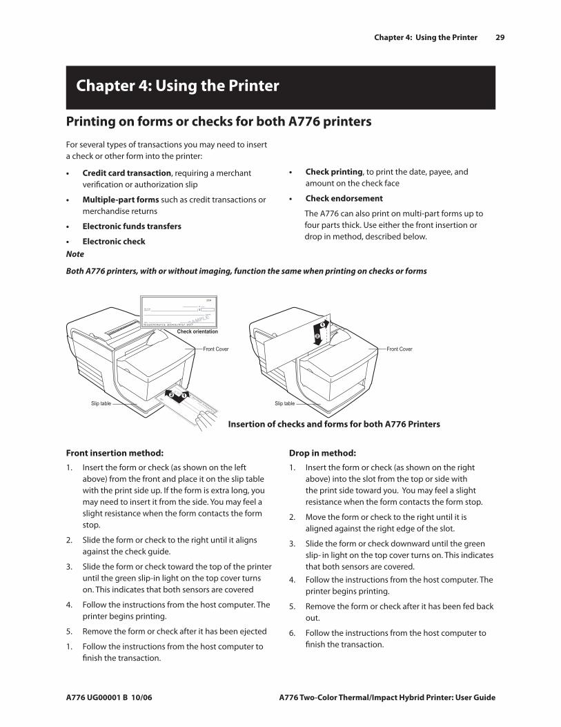
Front insertion method:
Insert the form or check (as shown on the left above) from the front and place it on the slip table with the print side up. If the form is extra long, you may need to insert it from the side. You may feel a slight resistance when the form contacts the form stop.
Slide the form or check to the right until it aligns against the check guide.
Slide the form or check toward the top of the printer until the green slip-in light on the top cover turns on. This indicates that both sensors are covered
Follow the instructions from the host computer. The printer begins printing.
Remove the form or check after it has been ejected
Follow the instructions from the host computer to finish the transaction.
1.
2.
3.
4.
5.
1.
Follow the instructions from the host computer. The printer begins printing.
Remove the form or check after it has been fed back out.
Follow the instructions from the host computer to finish the transaction.
4.
5.
6.
Drop in method:
Insert the form or check (as shown on the right above) into the slot from the top or side with the print side toward you. You may feel a slight resistance when the form contacts the form stop.
Move the form or check to the right until it is aligned against the right edge of the slot.
Slide the form or check downward until the green slip- in light on the top cover turns on. This indicates that both sensors are covered.
1.
2.
3.
12
Check orientation
Front Cover
Slip table
Front Cover
Slip table
A776 Print form_check 2.eps
1
2
Note
Both A776 printers, with or without imaging, function the same when printing on checks or forms
Insertion of checks and forms for both A776 Printers
30
A776 Two-Color Thermal/Impact Hybrid Printer: User Guide A776 UG00001 B 10/06
Chapter 4: Using the Printer
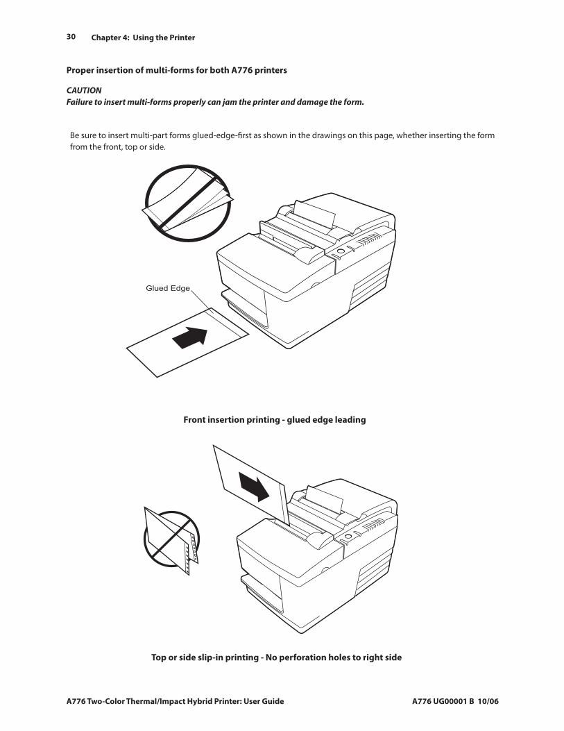
Be sure to insert multi-part forms glued-edge-first as shown in the drawings on this page, whether inserting the form from the front, top or side.
A776_B780 Forms YES.eps
Glued Edge
A776_B780 Forms YES.eps
Front insertion printing - glued edge leading
Top or side slip-in printing - No perforation holes to right side
CAUTION Failure to insert multi-forms properly can jam the printer and damage the form.
Proper insertion of multi-forms for both A776 printers
A776 UG00001 B 10/06 A776 Two-Color Thermal/Impact Hybrid Printer: User Guide
31Chapter 4: Using the Printer
To verify and validate a check inserted from the front:
Place the check face down on the slip table, with the bottom edge of the check to the right. Move the check to the right so it aligns along the check guide.
Slide the check straight forward into the printer until the green slip-in light on the top right edge of the printer comes on, indicating both sensors are covered.
Note
Hold the check to the right, against the check guide and release it as soon as the printer begins to run.
Follow the instructions on the host computer to complete the MICR process. The computer tells the printer to feed the check into the printer, read it, and then back it out again.
1.
2.
3.
Note
If the terminal indicates an incorrect read of the MICR:
Remove the check.
Reinsert the check, following steps 1, 2, and 3.
Remove the check only when it is fully released by the printer.
Continue to follow the instructions from the host computer to finish the transaction.
•
•
4.
5.
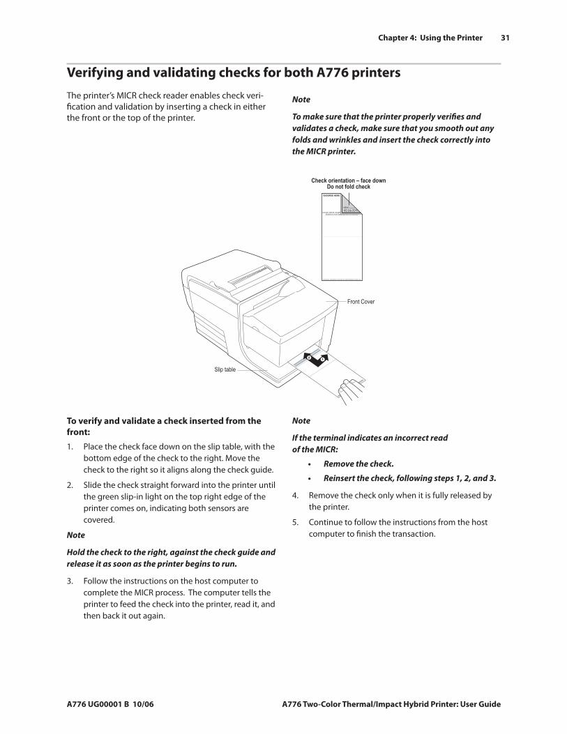
The printer’s MICR check reader enables check veri-fication and validation by inserting a check in either the front or the top of the printer.
Note
To make sure that the printer properly verifies and validates a check, make sure that you smooth out any folds and wrinkles and insert the check correctly into the MICR printer.
Verifying and validating checks for both A776 printers
Front Cover
Slip table
12
Check orientation – face downDo not fold check
A776 Validate_check.eps
32
A776 Two-Color Thermal/Impact Hybrid Printer: User Guide A776 UG00001 B 10/06
Chapter 4: Using the Printer
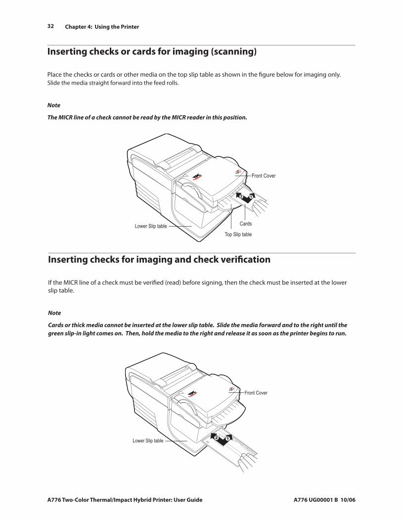
Inserting checks or cards for imaging (scanning)
Place the checks or cards or other media on the top slip table as shown in the figure below for imaging only. Slide the media straight forward into the feed rolls.
Note
The MICR line of a check cannot be read by the MICR reader in this position.
12
Front Cover
Lower Slip table
Top Slip table
Cards
Inserting checks for imaging and check verification
If the MICR line of a check must be verified (read) before signing, then the check must be inserted at the lower slip table.
Note
Cards or thick media cannot be inserted at the lower slip table. Slide the media forward and to the right until the green slip-in light comes on. Then, hold the media to the right and release it as soon as the printer begins to run.
12
Front Cover
Lower Slip table
A776 UG00001 B 10/06 A776 Two-Color Thermal/Impact Hybrid Printer: User Guide
33Chapter 4: Using the Printer
Tips for Avoiding Problems Prevent overheating of the print headOverheating of the thermal print head is one of the most common causes of printer problems. To avoid overheating do one or more of the following:
Reduce the amount of solid coverage when printing receipts.
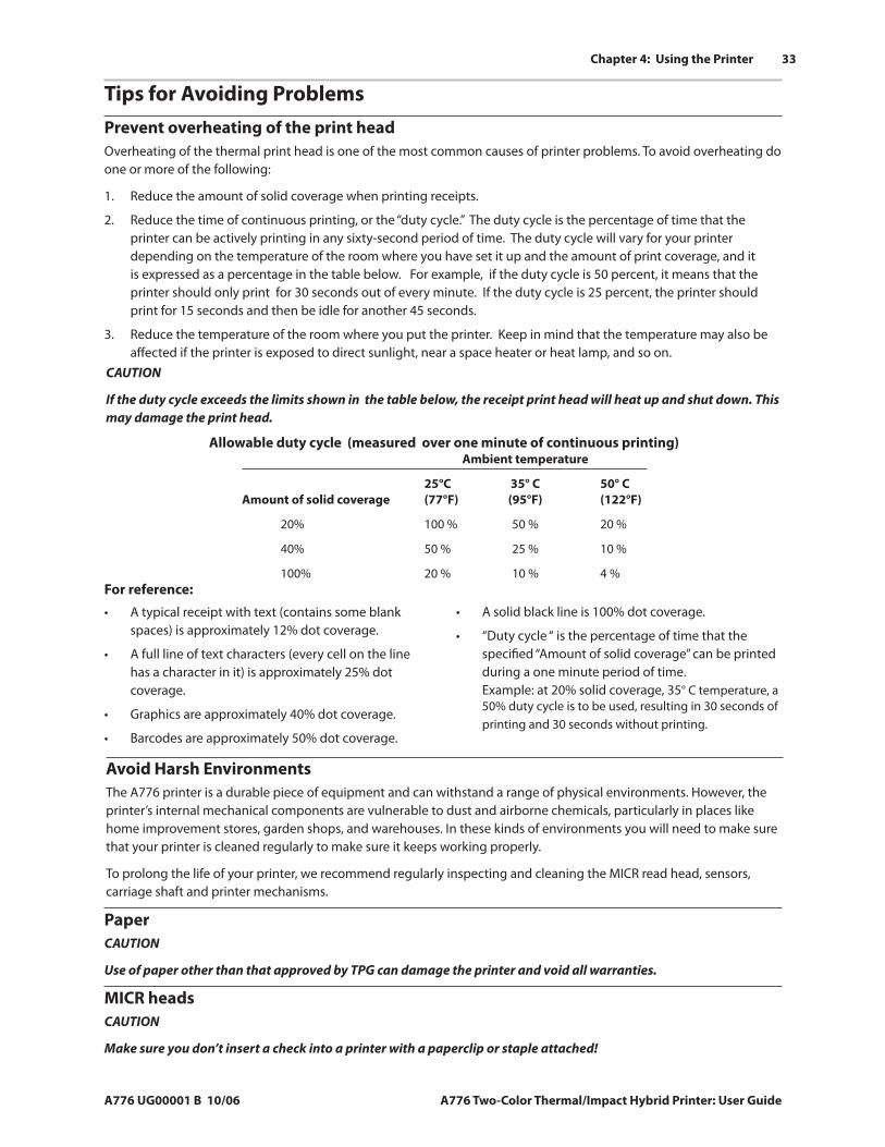
Reduce the time of continuous printing, or the “duty cycle.” The duty cycle is the percentage of time that the printer can be actively printing in any sixty-second period of time. The duty cycle will vary for your printer depending on the temperature of the room where you have set it up and the amount of print coverage, and it is expressed as a percentage in the table below. For example, if the duty cycle is 50 percent, it means that the printer should only print for 30 seconds out of every minute. If the duty cycle is 25 percent, the printer should print for 15 seconds and then be idle for another 45 seconds.
Reduce the temperature of the room where you put the printer. Keep in mind that the temperature may also be affected if the printer is exposed to direct sunlight, near a space heater or heat lamp, and so on.
1.
2.
3.
CAUTION
If the duty cycle exceeds the limits shown in the table below, the receipt print head will heat up and shut down. This may damage the print head.
Allowable duty cycle (measured over one minute of continuous printing)
Avoid Harsh EnvironmentsThe A776 printer is a durable piece of equipment and can withstand a range of physical environments. However, the printer’s internal mechanical components are vulnerable to dust and airborne chemicals, particularly in places like home improvement stores, garden shops, and warehouses. In these kinds of environments you will need to make sure that your printer is cleaned regularly to make sure it keeps working properly.
To prolong the life of your printer, we recommend regularly inspecting and cleaning the MICR read head, sensors, carriage shaft and printer mechanisms.
PaperCAUTION
Use of paper other than that approved by TPG can damage the printer and void all warranties.
MICR headsCAUTION
Make sure you don’t insert a check into a printer with a paperclip or staple attached!
For reference:
A typical receipt with text (contains some blank spaces) is approximately 12% dot coverage.
A full line of text characters (every cell on the line has a character in it) is approximately 25% dot coverage.
Graphics are approximately 40% dot coverage.
Barcodes are approximately 50% dot coverage.
•
•
•
•
A solid black line is 100% dot coverage.
“Duty cycle “ is the percentage of time that the specified “Amount of solid coverage” can be printed during a one minute period of time. Example: at 20% solid coverage, 35° C temperature, a 50% duty cycle is to be used, resulting in 30 seconds of printing and 30 seconds without printing.
•
•
Ambient temperature
25°C 35° C 50° C Amount of solid coverage (77°F) (95°F) (122°F)
20% 100 % 50 % 20 %
40% 50 % 25 % 10 %
100% 20 % 10 % 4 %
34
A776 Two-Color Thermal/Impact Hybrid Printer: User Guide A776 UG00001 B 10/06
Chapter 4: Using the Printer
Cleaning Cleaning the printer cabinetClean the outside cabinet as needed, using any household cleaner made for plastics. You may want to test a small unseen area first. Wipe the paper compartment with a clean, damp cloth. The cabinet materials and finish are durable and can tolerate cleaning solutions, lubricants, fuels, cooking oils, and ultraviolet light.
Cleaning the thermal print headWARNING
Don’t touch the thermal print head, as this can cause burns.
CAUTION
Do not attempt to clean the inside of the printer with any spray cleaner. Do not try to clean the thermal print head (except as recommended) or allow any spray to come in contact with it. This may damage the internal electronics or thermal print head.
If the print head appears dirty, wipe it with isopropyl (rubbing) alcohol on a cotton swab or alcohol pen.
CAUTION
Do not use the rubbing alcohol to clean any other parts of the printer! This may cause damage.
If spotty or light printing problems persist after cleaning the thermal print head, the thermal print mechanism may need to be replaced.
CAUTION
The thermal print head does not normally require cleaning when recommended paper grades are used. If you use paper not approved by TPG paper over an extended period, attempting to clean the thermal print head will have little effect on the print quality and could cause jamming and other damage to the printer, voiding the warranty
Cleaning Out Paper DustWe suggest that you remove paper dust from your printer every six months or so, using canned air or some other kind of fan to blow the dust out of the printer.
Cleaning rollers, MICR, and imagerWe suggest that you clean the two contact image sensors every six months or so, using a cotton swab and rubbing alcohol.
A776 UG00001 B 10/06 A776 Two-Color Thermal/Impact Hybrid Printer: User Guide
35Chapter 4: Using the Printer
Paper JamsClearing a receipt paper jam in all printers
While holding the smooth paper over the front of the cabinet, firmly press the receipt cover closed.
Remove the excess paper by tearing it against the tear-off blade.
Press the paper feed button to advance the paper if necessary.
Run a diagnostics test to assure the printer is communicating with the host computer (see page 22)
4.
5.
6.
7.
Clearing a paper jam in the slip path for all printers
To clear a paper jam in the slip paper pass:
On printers without imaging, open the front cover by grasping the cover on each side near the top and swing the cover up and towards you.
Note
On printers with imaging, release the front cover with the cover latch (button).
On printers with an imaging module, on the right side of the front cover, near the paper feed button, press the curved front cover release button toward the front and carefully swing the cover up and towards you.
On either printer, grasp the jammed paper and draw it out.
1.
2.
3.
When the paper is torn or cannot be drawn out:
Open the receipt cover.
Using a pen or pencil, press the reset button. This should open the platten to relieve any pressure on the paper jam.
Clear the paper jam.
Close the receipt cover.
CAUTION
On a printer with an imaging module, when the print head is all the way to the right, move the print head to the left, otherwise the front cover may not close and could be damaged.
Close the front cover.
4.
a.
b.
5.
6.
7.
Clearing a jam in the imager unit
To clear a jam in the imager unit, proceed as follows:
When a paper jam extends out the top front end or rear of the imager unit, carefully pull the paper back out of the imager.
To get a better grip on the paper:
On the right side of the printer near the paper feed button, press the cover latch button toward the front and swing the cover open.
Grasp the jammed paper and carefully pull the paper out of the imager.
1.
2.
a.
b.
When nothing extends out either end of the imager that can be grasped:
On the left side of the imager unit there is a small round hole. Insert either the tip of a ball point pen or opened paper clip into the hole. Open the imager cover from the back.
Remove any paper or laminated stock that is jammed in the imager.
3.
a.
b.
Close the imager cover.
Close the front cover.
4.
5.
To clear a receipt paper jam proceed as follows:
On each side of the receipt cover, near where the receipt emerges, there is a lip. Using one finger from each hand, firmly raise the receipt cover.
Draw the crumpled portion of the paper out of the printer until the smooth portion extends a few inches over the cabinet front.
When there is paper jammed into the roller in the receipt cover, draw the paper out from the roller.
Note
Paper must unroll from the bottom of the roll to ensure that the image prints.
1.
2.
3.
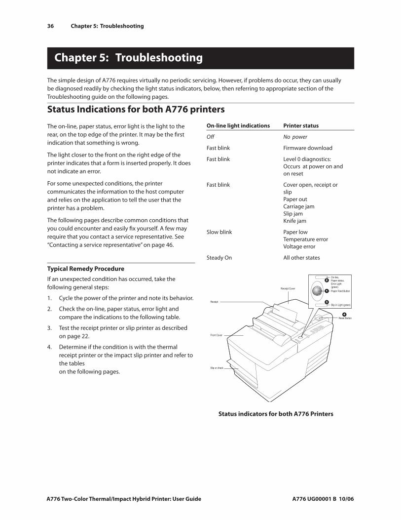
36 Chapter 5: Troubleshooting
A776 Two-Color Thermal/Impact Hybrid Printer: User Guide A776 UG00001 B 10/06
Status Indications for both A776 printers
The on-line, paper status, error light is the light to the rear, on the top edge of the printer. It may be the first indication that something is wrong.
The light closer to the front on the right edge of the printer indicates that a form is inserted properly. It does not indicate an error.
For some unexpected conditions, the printer communicates the information to the host computer and relies on the application to tell the user that the printer has a problem.
The following pages describe common conditions that you could encounter and easily fix yourself. A few may require that you contact a service representative. See “Contacting a service representative” on page 46.
Typical Remedy Procedure
If an unexpected condition has occurred, take the following general steps:
Cycle the power of the printer and note its behavior.
Check the on-line, paper status, error light and compare the indications to the following table.
Test the receipt printer or slip printer as described on page 22.
Determine if the condition is with the thermal receipt printer or the impact slip printer and refer to the tables on the following pages.
1.
2.
3.
4.
On-line light indications Printer status
Off No power
Fast blink Firmware download
Fast blink Level 0 diagnostics: Occurs at power on and on reset
Fast blink Cover open, receipt or slip Paper out Carriage jam Slip jam Knife jam
Slow blink Paper low Temperature error Voltage error
Steady On All other states
The simple design of A776 requires virtually no periodic servicing. However, if problems do occur, they can usually be diagnosed readily by checking the light status indicators, below, then referring to appropriate section of the Troubleshooting guide on the following pages.
Chapter 5: Troubleshooting
Status indicators for both A776 Printers
Receipt Cover
Reset Button
Front Cover
Receipt
Slip or check
On-line,
Paper status,
Error Light
(green)
Paper Feed Button
Slip in Light (green)
1
3
2
4
Chapter 5: Troubleshooting
A776 UG00001 B 10/06 A776 Two-Color Thermal/Impact Hybrid Printer: User Guide
37
Printer beepsCondition Possible causes What to do
Printer beeps in a single, double, or The printer has a problem Contact a service representative. triple pattern at first power on. with its electronics. The on-line paper status error light blinks in the same pattern, and the printer won’t power up.
Printer beeps during normal The printer may be programmed Consult your application software operation. to beep during normal operation manual. by the software application used on the host computer.
Printer will not printCondition Possible causes What to do
The on-line, paper status, or error light The receipt paper may be out, the Check that the receipt paper is properly blinks and the printer won’t cover open, the knife jammed, the loaded and covers are closed. See the print. supply voltage out of range, or the table on page 41. If the problem print head temperature out of range. continues, contact a service representative.
Printer has no power (light not on) Power supply may be defective. If the power supply is plugged in but does not come on, you need to order a new power supply. Contact a service representative.
Printer has power, doesn’t Cables may not be connected Check all cable connections. Check print properly. that the host computer and power supply are both on (the power supply is turned on by plugging it into a live outlet). Look for the green power light to show that the printer has power . See “Connect the cables” on page 19.
DIP switches not set correctly. On rear of printer, check the switch setting. DIP switch one should be off (up) for normal operation.
All other causes. Contact a service representative.
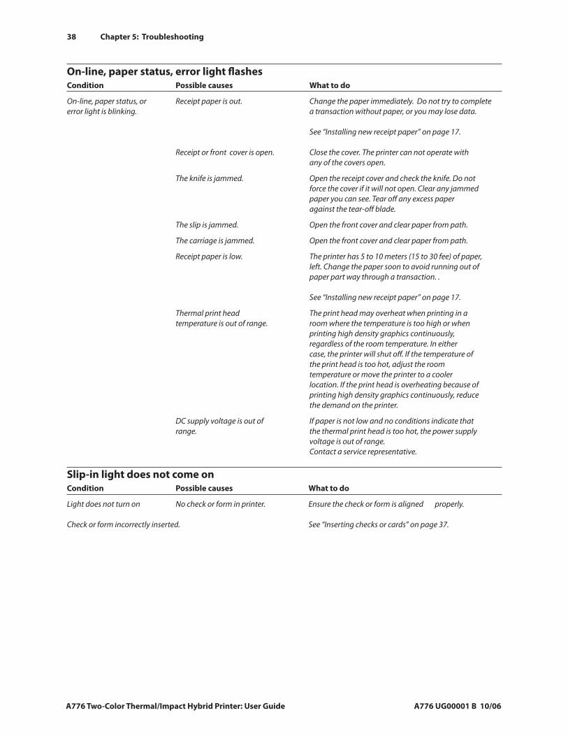
38 Chapter 5: Troubleshooting
A776 Two-Color Thermal/Impact Hybrid Printer: User Guide A776 UG00001 B 10/06
On-line, paper status, error light flashesCondition Possible causes What to do
On-line, paper status, or Receipt paper is out. Change the paper immediately. Do not try to complete error light is blinking. a transaction without paper, or you may lose data. See “Installing new receipt paper” on page 17. Receipt or front cover is open. Close the cover. The printer can not operate with any of the covers open.
The knife is jammed. Open the receipt cover and check the knife. Do not force the cover if it will not open. Clear any jammed paper you can see. Tear off any excess paper against the tear-off blade.
The slip is jammed. Open the front cover and clear paper from path.
The carriage is jammed. Open the front cover and clear paper from path.
Receipt paper is low. The printer has 5 to 10 meters (15 to 30 fee) of paper, left. Change the paper soon to avoid running out of paper part way through a transaction. . See “Installing new receipt paper” on page 17.
Thermal print head The print head may overheat when printing in a temperature is out of range. room where the temperature is too high or when printing high density graphics continuously, regardless of the room temperature. In either case, the printer will shut off. If the temperature of the print head is too hot, adjust the room temperature or move the printer to a cooler location. If the print head is overheating because of printing high density graphics continuously, reduce the demand on the printer.
DC supply voltage is out of If paper is not low and no conditions indicate that range. the thermal print head is too hot, the power supply voltage is out of range. Contact a service representative.
Slip-in light does not come on Condition Possible causes What to do
Light does not turn on No check or form in printer. Ensure the check or form is aligned properly. Check or form incorrectly inserted. See “Inserting checks or cards” on page 37.
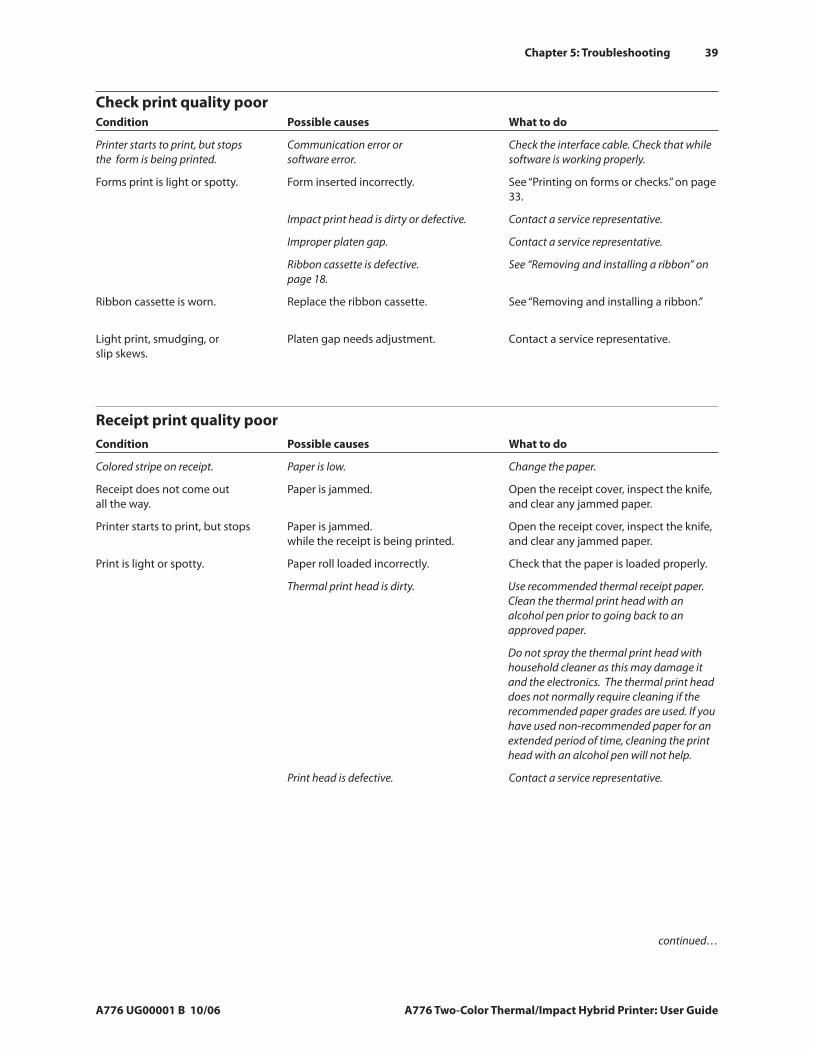
Chapter 5: Troubleshooting
A776 UG00001 B 10/06 A776 Two-Color Thermal/Impact Hybrid Printer: User Guide
39
Check print quality poor Condition Possible causes What to do
Printer starts to print, but stops Communication error or Check the interface cable. Check that while the form is being printed. software error. software is working properly.
Forms print is light or spotty. Form inserted incorrectly. See “Printing on forms or checks.” on page 33.
Impact print head is dirty or defective. Contact a service representative.
Improper platen gap. Contact a service representative.
Ribbon cassette is defective. See “Removing and installing a ribbon” on page 18.
Ribbon cassette is worn. Replace the ribbon cassette. See “Removing and installing a ribbon.”
Light print, smudging, or Platen gap needs adjustment. Contact a service representative. slip skews.
Receipt print quality poorCondition Possible causes What to do
Colored stripe on receipt. Paper is low. Change the paper.
Receipt does not come out Paper is jammed. Open the receipt cover, inspect the knife, all the way. and clear any jammed paper.
Printer starts to print, but stops Paper is jammed. Open the receipt cover, inspect the knife, while the receipt is being printed. and clear any jammed paper.
Print is light or spotty. Paper roll loaded incorrectly. Check that the paper is loaded properly.
Thermal print head is dirty. Use recommended thermal receipt paper. Clean the thermal print head with an alcohol pen prior to going back to an approved paper.
Do not spray the thermal print head with household cleaner as this may damage it and the electronics. The thermal print head does not normally require cleaning if the recommended paper grades are used. If you have used non-recommended paper for an extended period of time, cleaning the print head with an alcohol pen will not help.
Print head is defective. Contact a service representative.
continued…
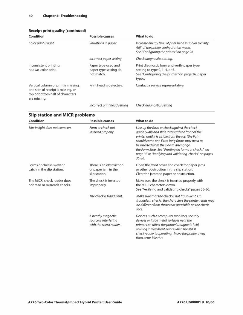
40 Chapter 5: Troubleshooting
A776 Two-Color Thermal/Impact Hybrid Printer: User Guide A776 UG00001 B 10/06
Receipt print quality (continued) Condition Possible causes What to do
Color print is light. Variations in paper. Increase energy level of print head in “Color Density Adj” of the printer configuration menu. See “Configuring the printer” on page 26.
Incorrect paper setting Check diagnostics setting.
Inconsistent printing, Paper type used and Print diagnostic form and verify paper type no two-color print. paper type setting do setting to type 0, 1, 4, or 5. not match. See “Configuring the printer” on page 26, paper types.
Vertical column of print is missing, Print head is defective. Contact a service representative. one side of receipt is missing, or top or bottom half of characters are missing.
Incorrect print head setting Check diagnostics setting
Slip station and MICR problemsCondition Possible causes What to do
Slip-in light does not come on. Form or check not Line up the form or check against the check inserted properly. guide (wall) and slide it toward the front of the printer until it is visible from the top (the light should come on). Extra long forms may need to be inserted from the side to disengage the Form Stop. See “Printing on forms or checks” on page 33 or “Verifying and validating checks” on pages 35-36.
Forms or checks skew or There is an obstruction Open the front cover and check for paper jams catch in the slip station. or paper jam in the or other obstruction in the slip station. slip station. Clear the jammed paper or obstruction.
The MICR check reader does The check is inserted Make sure the check is inserted properly with not read or misreads checks. improperly. the MICR characters down. See “Verifying and validating checks” pages 35-36.
The check is fraudulent. Make sure that the check is not fraudulent. On fraudulent checks, the characters the printer reads may be different from those that are visible on the check face.
A nearby magnetic Devices, such as computer monitors, security source is interfering devices or large metal surfaces near the with the check reader. printer can affect the printer’s magnetic field, causing intermittent errors when the MICR check reader is operating. Move the printer away from items like this.
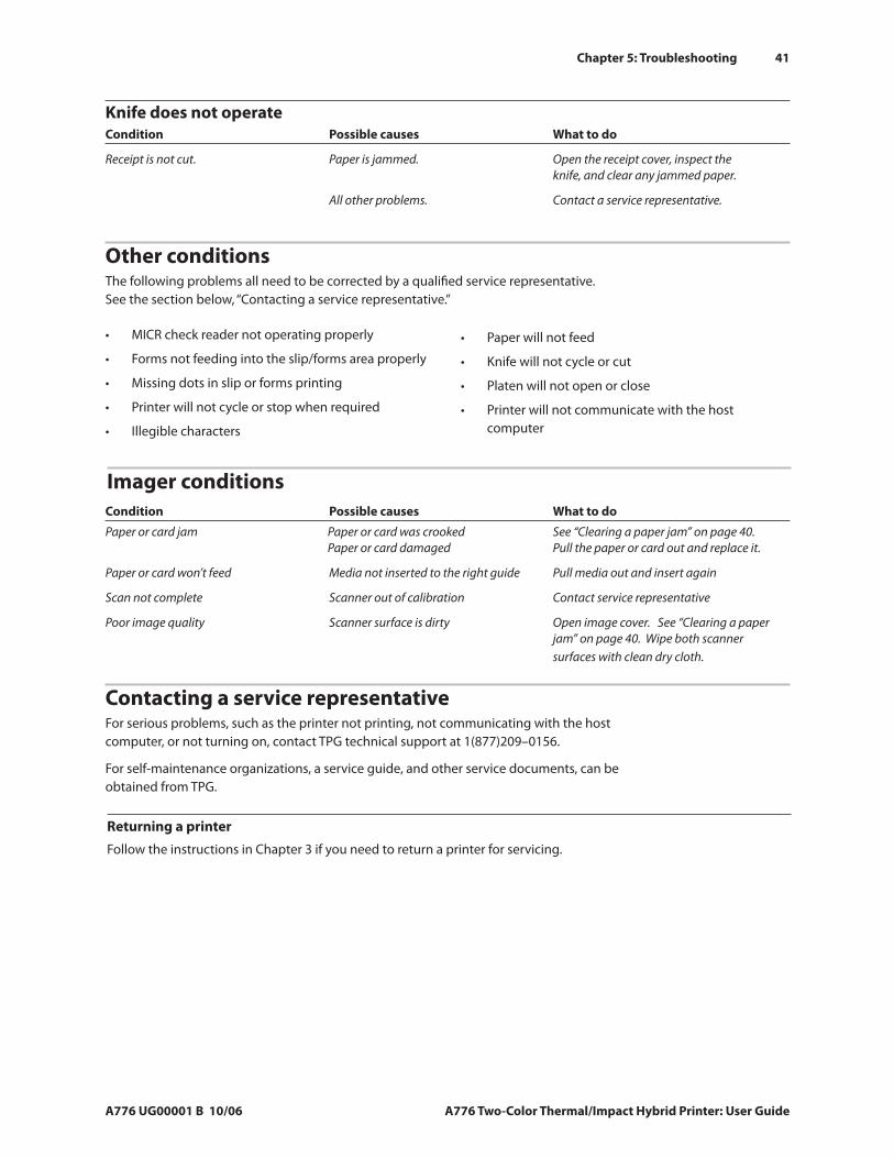
Chapter 5: Troubleshooting
A776 UG00001 B 10/06 A776 Two-Color Thermal/Impact Hybrid Printer: User Guide
41
Knife does not operateCondition Possible causes What to do
Receipt is not cut. Paper is jammed. Open the receipt cover, inspect the knife, and clear any jammed paper.
All other problems. Contact a service representative.
Other conditionsThe following problems all need to be corrected by a qualified service representative. See the section below, “Contacting a service representative.”
MICR check reader not operating properly
Forms not feeding into the slip/forms area properly
Missing dots in slip or forms printing
Printer will not cycle or stop when required
Illegible characters
•
•
•
•
•
Contacting a service representativeFor serious problems, such as the printer not printing, not communicating with the host computer, or not turning on, contact TPG technical support at 1(877)209–0156.
For self-maintenance organizations, a service guide, and other service documents, can be obtained from TPG.
Paper will not feed
Knife will not cycle or cut
Platen will not open or close
Printer will not communicate with the host computer
•
•
•
•
Returning a printer
Follow the instructions in Chapter 3 if you need to return a printer for servicing.
Imager conditionsCondition Possible causes What to do
Paper or card jam Paper or card was crooked See “Clearing a paper jam” on page 40. Paper or card damaged Pull the paper or card out and replace it.
Paper or card won’t feed Media not inserted to the right guide Pull media out and insert again
Scan not complete Scanner out of calibration Contact service representative
Poor image quality Scanner surface is dirty Open image cover. See “Clearing a paper jam” on page 40. Wipe both scanner surfaces with clean dry cloth.
42 Chapter 6: Ordering Paper and Supplies
A776 Two-Color Thermal/Impact Hybrid Printer: User Guide A776 UG00001 B 10/06
Chapter 6: Ordering Paper and supplies
Ordering from TPGPrinter parts, accessories, and small quantities of paper can be ordered directly from TPG. While the TPG part numbers are listed here for your convenience, keep in mind that these numbers may change before this guide is updated. To place an order or get more information, call your TPG representative or the sales line at (800) 732-8950.
TPG can provide paper in small lots for product evaluation and testing. Contact your TPG representative for more details.
Ordering thermal paperThermal paper specificationsThe printer requires qualified thermal paper with the following dimensions:
Width Diameter Length
80 ± 0.2 mm (3.15 ± 0.02”) 83 mm max. (3.27”) 98 meters (321 ‘) 2.4 mil thick
The paper must not be attached at the core. Use paper with a colored stripe at the end to indicate that the paper is running low.
The above lengths are based on a core diameter of 22 ± 0.5 mm (0.87”) outside, 11.5 ± 0.5 mm (0.45”) inside.
Manufacturers
Contact the converter of your choice to order paper. TPG recommends the following paper grades produced by their respective manufacturers. There are a number of paper converters qualified to provide this paper, provided the POS rolls are from these recommended grades.
Note
When changing paper type, you need to set the printer to that paper type by sending the “Set paper type” command (1D 81 m n) or by changing the paper type setting in the configuration menu.
Monochrome (black ink) paper:Qualified manufacturers Phone Paper grade (density)
Appleton Papers, Inc. (USA) Voice: (800) 922–1729 Optima T1030 (Light) 825 E. Wisconsin Ave. Fax: (800) 922–1712 Optima T1012A (Standard) Appleton, WI 54912 Optima POS-Plus (Light) Optima T2162 (Light) Optima Superior (Standard)
Kanzaki Specialty Papers (USA) Voice: (888) 526–9254 P–300 (Light) 20 Cummings St. Fax: (413) 731–8864 P–310 (Standard) Ware, MA 01082–2002 P–350 (Standard) P–354 (Standard) P–390 (Standard) TO–260 (Standard) TO–381L (Standard)
Jujo Thermal LTD. Voice: (358) 2–8393–2900 AF50KS–E3 (Standard) P.O. Box 92 FIN–27501 Fax: (358) 2–3893–2419 AP62KS–E3 (Standard) Kauttua, Finland
Continued next page…
Chapter 6: Ordering Paper and Supplies
A776 UG00001 B 10/06 A776 Two-Color Thermal/Impact Hybrid Printer: User Guide
43
Ordering paper from TPGTo order monochrome paper rolls directly from TPG, use the following part numbers:
Standard density 50 Rolls, 90 mm dia. TPG #A152–0034
Light density 50 Rolls, 90 mm dia. TPG #A152–0035
Ordering miscellaneous suppliesCash drawers
M-S Cash Drawer Corp. EP–125 K seriesTM, EP–127, EP–102TM
APG Cash Drawer Model 322TM
Indiana Cash Drawer Model SLDTM
Mitsubishi Int’l Corp (USA) Voice: (212) 605–2000 P–5035 (Light) 520 Madison Ave. Fax: (212) 605–2597 T–8051 (Standard) New York, New York 10022-4223 TP–8065 (Standard)
OJI Paper Company Ltd. Voice: (81) 3–5550–3076 KF–60 (Standard) 5–12–8 Ginza Chuo-ku Fax: (81) 3–5550–2950 PD–170R (Light) Tokyo 104, Japan PD–160R (Standard)
Two-color paper:Qualified manufacturers Phone Paper grade (density)
Kanzaki Specialty Papers (USA) Voice: (888) 526–9254 P–310 RB (Red and Black) 20 Cummings St. Fax: (413) 731–8864 P–320 RB (Red and Black) Ware, MA 01082–2002 P–320 BB (Blue and Black)
Order cash drawers from the following suppliers:
Cash drawers Number
NCR 7052–K657TM
44 Chapter 6: Ordering Paper and Supplies
A776 Two-Color Thermal/Impact Hybrid Printer: User Guide A776 UG00001 B 10/06
Item Type Number
55-watt power supply with attached A776–K330 cable to printer and U.S. power supply cord
75-watt power supply with attached A776–K331 cable to the printer and U.S. power supply cord
55-watt power supply, attached cable A776–K301
75-watt power supply, attached cable A776–K302
Power supply cord (to outlet) United States A776–K320 International (no plug) A776–K321 United Kingdom A776–K322 S.E.V. A776–K323 Australia A776–K324 International (with plug) A795–K326
6-pin female to 3-pin male power adapter A776–K303
3-pin female to 6-pin male power adapter A776–K304
Power supply mounting bracket A776–K309
Communication cables Length Order number
RS-232C 25-pin male (printer) (2 meters–6.6 feet) A141–0005 to 9 pin female (host)
RS-232C 25-pin male (printer) (6 meters–19.7 feet) A141–0006 to 9 pin female (host)
RS-232C 9-pin female (printer) (3 meters–9.8 feet) A141–0008 to 25-pin female (host)
RS-232C 9-pin female (printer) (3 meters–9.8 feet) A141–0007 to 9-pin female (ferrite-host)
USB Not available*
Ethernet Not available
* Obtain a standard 3 meter (9.8 foot) USB cable from any supplier.
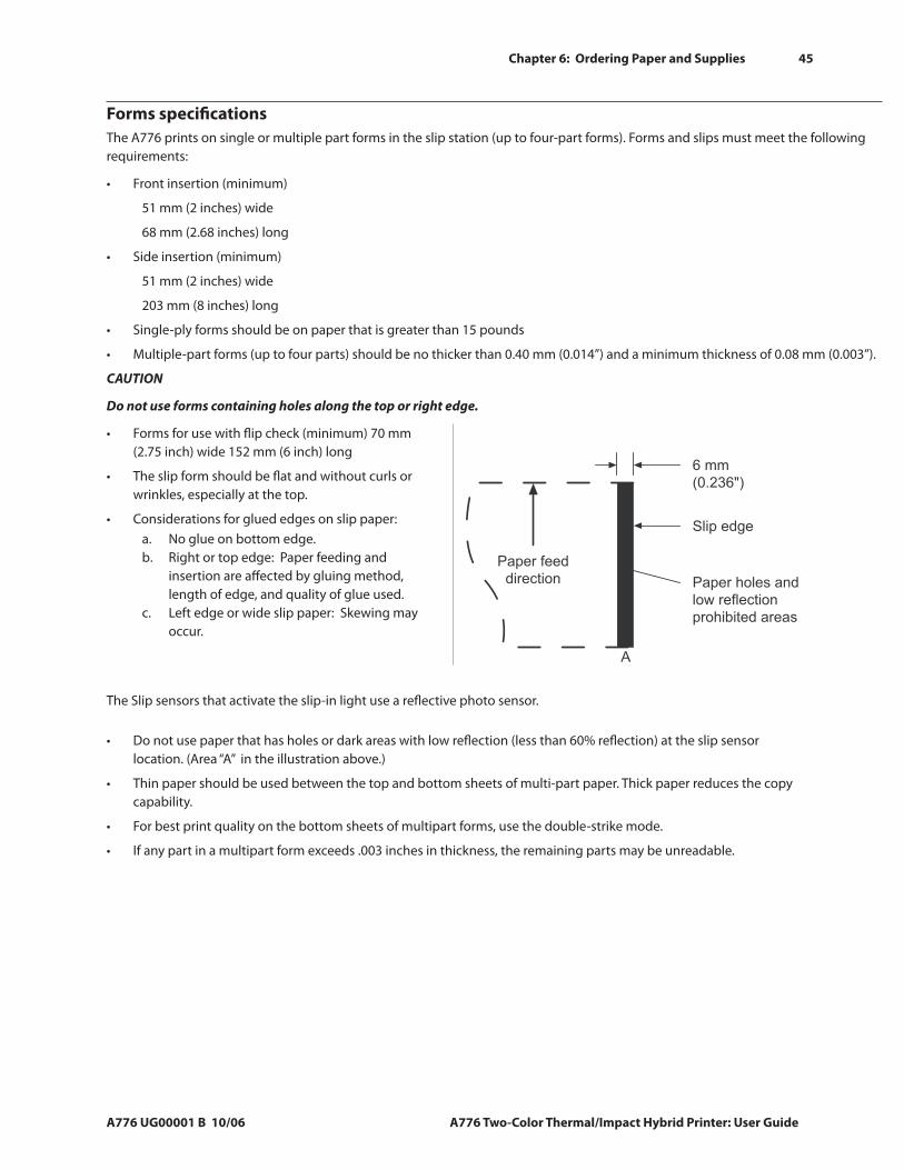
Chapter 6: Ordering Paper and Supplies
A776 UG00001 B 10/06 A776 Two-Color Thermal/Impact Hybrid Printer: User Guide
45
Forms specificationsThe A776 prints on single or multiple part forms in the slip station (up to four-part forms). Forms and slips must meet the following requirements:
Front insertion (minimum)
51 mm (2 inches) wide
68 mm (2.68 inches) long
Side insertion (minimum)
51 mm (2 inches) wide
203 mm (8 inches) long
Single-ply forms should be on paper that is greater than 15 pounds
Multiple-part forms (up to four parts) should be no thicker than 0.40 mm (0.014”) and a minimum thickness of 0.08 mm (0.003”).
CAUTION
Do not use forms containing holes along the top or right edge.
Forms for use with flip check (minimum) 70 mm (2.75 inch) wide 152 mm (6 inch) long
The slip form should be flat and without curls or wrinkles, especially at the top.
Considerations for glued edges on slip paper:No glue on bottom edge.Right or top edge: Paper feeding and insertion are affected by gluing method, length of edge, and quality of glue used.Left edge or wide slip paper: Skewing may occur.
•
•
•
•
•
•
•a.b.
c.
The Slip sensors that activate the slip-in light use a reflective photo sensor.
Do not use paper that has holes or dark areas with low reflection (less than 60% reflection) at the slip sensor location. (Area “A” in the illustration above.)
Thin paper should be used between the top and bottom sheets of multi-part paper. Thick paper reduces the copy capability.
For best print quality on the bottom sheets of multipart forms, use the double-strike mode.
If any part in a multipart form exceeds .003 inches in thickness, the remaining parts may be unreadable.
•
•
•
•
Paper feed
direction Paper holes and
low reflection
prohibited areas
Slip edge
6 mm
(0.236")
A
A776 Slip Form Recom.eps
46 Chapter 6: Ordering Paper and Supplies
A776 Two-Color Thermal/Impact Hybrid Printer: User Guide A776 UG00001 B 10/06
Check specificationsCheck specifications for paper are defined by American Standards ANSI X9.13 and ANSI X9.18, and International Standard ISO 1004.
Minimum check size: 70 mm (2.75 inch) wide x 152 mm (6 inch) long
Maximum check size: 95 mm (3.75 inch) wide x 222 mm (8.75 inch) long
MICR reader – additional information
For best results the check should be flat and free of curls, folds, or wrinkles (especially at the edges). Wrinkled checks may rub against the ribbon causing them to get ink stains.
Checks not have paperclips or staples. Paper jams, MICR read errors, and damage to the MICR head can occur.
Immediately release the check once the printer starts to feed it. Failure to release the check could skew it, causing paper jams and MICR read errors.
Ordering ribbon cassettesTo order ribbon cassettes, contact your sales representative or order from TPG at the following address or toll free number:
TPG Inc. 5893 Oberlin Dr., Suite 103
San Diego, CA 92121
Call toll-free: (800) 548–7862 x5040
CAUTION
Use of other than an approved TPG ribbon cassette can void all warranties and cause damage from jamming and other ribbon problems.
Stock numbers: A152–0041 (purple long life ribbon cassette—5 million character life) – Qty. 12
A152–0042 (black long life ribbon cassette—5 million character life) – Qty. 12
Documentation and LogoEZ® utilityContact a sales representative to order the following:
A776 User Guide* A776–UG00001
A776/B780 Programming Guide* A776–PG00001
A776/B780 Service Guide A776–SERV001 (TPG certified service technicians only)
A776 Setup Guide* A776–SUG0001
TPG LogoEZ® colorization utility
* Downloadable from the TPG Web site www.tpgprinters.com (documentation provided in pdf format)
•
•
•
•
•

A776–UG00001 B 10/06