Embed Size (px)
Citation preview
User Guide
SBG940 Wireless Cable Modem Gateway
Overview Installation Troubleshooting Contact FAQ Specifications Glossary LicenseConfiguration: Basic Gateway TCP/IP Wireless USB
SBG940 User Guide ii
WARNING: TO PREVENT FIRE OR SHOCK HAZARD, DO NOT EXPOSE THIS PRODUCT TO RAIN OR MOISTURE. THE UNIT MUST NOT BE EXPOSED TO DRIPPING OR SPLASHING. DO NOT PLACE OBJECTS FILLED WITH LIQUIDS, SUCH AS VASES, ON THE UNIT.
CAUTION: TO PREVENT ELECTRIC SHOCK, THIS EQUIPMENT MAY REQUIRE A GROUNDING CONDUCTOR IN THE LINE CORD. CONNECT THE UNIT TO A GROUNDING TYPE AC WALL OUTLET USING THE POWER CORD SUPPLIED WITH THE UNIT.
CAUTION: THIS PRODUCT WAS QUALIFIED UNDER TEST CONDITIONS THAT INCLUDED THE USE OF THE SUPPLIED CABLES BETWEEN SYSTEMS COMPONENTS. TO ENSURE REGULATORY AND SAFETY COMPLIANCE, USE ONLY THE PROVIDED POWER AND INTERFACE CABLES AND INSTALL THEM PROPERLY.
CAUTION: DIFFERENT TYPES OF CORD SETS MAY BE USED FOR CONNECTIONS TO THE MAIN SUPPLY CIRCUIT. USE ONLY A MAIN LINE CORD THAT COMPLIES WITH ALL APPLICABLE PRODUCT SAFETY REQUIREMENTS OF THE COUNTRY OF USE.
CAUTION: INSTALLATION OF THIS PRODUCT MUST BE IN ACCORDANCE WITH NATIONAL WIRING CODES AND CONFORM TO LOCAL REGULATIONS.
CAUTION: DO NOT OPEN THE UNIT. DO NOT PERFORM ANY SERVICING OTHER THAN THAT CONTAINED IN THE INSTALLATION AND TROUBLESHOOTING INSTRUCTIONS. REFER ALL SERVICING TO QUALIFIED SERVICE PERSONNEL.
CAUTION: CHANGES AND MODIFICATIONS NOT EXPRESSLY APPROVED BY MOTOROLA FOR COMPLIANCE COULD VOID USER’S AUTHORITY TO OPERATE THE EQUIPMENT.
When using this device, basic safety precautions should always be followed to reduce the risk of fire, electric shock and injury to persons, including the following:
• Read all of the instructions listed here and/or in the user manual before you operate this equipment. Give particular attention to all safety precautions. Retain the instructions for future reference.
• This device must be installed and used in strict accordance with manufacturer’s instructions as described in the user documentation that comes with the product.
• Comply with all warning and caution statements in the instructions. Observe all warning and caution symbols that are affixed to this equipment.
• Comply with all instructions that accompany this equipment.
• Do not overload outlets or extension cords, as this can result in a risk of fire or electric shock. Overloaded AC outlets, extension cords, frayed power cords, damaged or cracked wire insulation, and broken plugs are dangerous. They may result in a shock or fire hazard.
• Route power supply cords so that they are not likely to be walked on or pinched by items placed upon or against them. Pay particular attention to cords where they are attached to plugs and convenience receptacles, and examine the point where they exit from the product.
• Place this equipment in a location that is close enough to an electrical outlet to accommodate the length of the power cord.
• Place unit to allow for easy access when disconnecting the power cord of the device from the AC wall outlet.
• Do not connect the plug into an extension cord, receptacle, or other outlet unless the plug can be fully inserted with no part of the blades exposed.
• Place this equipment on a stable surface.
Overview Installation Troubleshooting Contact FAQ Specifications Glossary LicenseConfiguration: Basic Gateway TCP/IP Wireless USB
SBG940 User Guide iii
• Postpone cable modem installation until there is no risk of thunderstorm or lightning activity in the area.
• Avoid using this product during an electrical storm. There may be a risk of electric shock from lightning. For added protection for this product during a lightning storm, or when it is left unattended and unused for long periods of time, unplug it from the wall outlet, and disconnect the cable system. This will prevent damage to the product due to lightning and power surges.
• It is recommended that the customer install an AC surge protector in the AC outlet to which this device is connected. This is to avoid damaging the equipment by local lightning strikes and other electrical surges.
• Do not cover the device, or block the airflow to the device with any other objects. Keep the device away from excessive heat and humidity and keep the device free from vibration and dust.
• Wipe the unit with a clean, dry cloth. Never use cleaning fluid or similar chemicals. Do not spray cleaners directly on the unit or use forced air to remove dust.
• Avoid damaging the cable modem with static by touching the coaxial cable when it is attached to the earth grounded coaxial cable TV wall outlet.
• Always first touch the coaxial cable connector on the cable modem when disconnecting or re-connecting USB or Ethernet cable from the cable modem or the user’s PC.
• Operate this product only from the type of power source indicated on the product’s marking label. If you are not sure of the type of power supplied to your home, consult your dealer or local power company.
• Upon completion of any service or repairs to this product, ask the service technician to perform safety checks to determine that the product is in safe operating condition.
Caring for the Environment by RecyclingWhen you see this symbol on a Motorola product, do not dispose of the product with residential or commercial waste.Recycling your Motorola EquipmentPlease do not dispose of this product with your residential or commercial waste. Some countries or regions, such as the European Union, have set up systems to collect and recycle electrical and electronic waste items. Contact your local authorities for information about practices established for your region. If collection systems are not available, call Motorola Customer Service for assistance.
Overview Installation Troubleshooting Contact FAQ Specifications Glossary LicenseConfiguration: Basic Gateway TCP/IP Wireless USB
SBG940 User Guide iv
Be sure that the outside cable system is grounded, so as to provide some protection against voltage surges and built-up static charges. Article 820-20 of the NEC (Section 54, Part I of the Canadian Electrical Code) provides guidelines for proper grounding and, in particular, specifies the CATV cable ground shall be connected in the grounding system of the building, as close to the point of cable entry as practical.
Apparaten skall anslutas till jordat uttag när den ansluts ett näverk.
FCC Compliance Class B Digital Device
This device complies with part 15 of the FCC Rules. Operation is subject to the following two conditions: (1) This device may not cause harmful interference, and (2) this device must accept any interference received, including interference that may cause undesired operation.
Note: This equipment has been tested and found to comply with the limits for a Class B digital device, pursuant to part 15 of the FCC Rules. These limits are designed to provide reasonable protection against harmful interference in a residential installation. This equipment generates, uses and can radiate radio frequency energy and, if not installed and used in accordance with the instructions, may cause harmful interference to radio communications. However, there is no guarantee that interference will not occur in a particular installation. If this equipment does cause harmful interference to radio or television reception, which can be determined by turning the equipment off and on, the user is encouraged to try to correct the interference by one or more of the following measures:
• Reorient or relocate the receiving antenna.
• Increase the separation between the equipment and receiver.
• Connect the equipment into an outlet on a circuit different from that to which the receiver is connected.
• Consult the dealer or an experienced radio/TV technician for help.
Overview Installation Troubleshooting Contact FAQ Specifications Glossary LicenseConfiguration: Basic Gateway TCP/IP Wireless USB
SBG940 User Guide v
FCC CertificationThis product contains a radio transmitter and accordingly has been certified as compliant with 47 CFR Part 15 of the FCC Rules for intentional radiators. Products that contain a radio transmitter are labeled with FCC ID and the FCC logo.
CAUTION: Exposure to Radio Frequency Radiation.To comply with the FCC RF exposure compliance requirements, the separation distance between the antenna and any person’s body (including hands, wrists, feet and ankles) must be at least 20 cm (8 inches).
Canada - Industry Canada (IC)The wireless radio of this device complies with RSS 210 and RSS 102 of Industry Canada.
This Class B digital device complies with Canadian ICES-003.
Cet appareil numérique de la classe B est conforme à la norme NMB-003 du Canada.
To prevent radio interference to the licensed service, this device is intended to be operated indoors and away from windows to provide maximum shielding. Equipment (or its transmit antenna) that is installed outdoors is subject to licensing.
This device has been designed to operate with an antenna having a maximum gain of 9 dBi. Antenna having a higher gain is strictly prohibited per regulations of Industry Canada. The required antenna impedance is 50 ohms.
To reduce potential radio interference to other users, the antenna type and its gain should be so chosen that the equivalent isotropically radiated power (EIRP) is not more than that required for successful communication.
Only use the antenna(s) provided with this product or an antenna approved by Motorola.
Regulatory, Safety, Software License, and Warranty Information Card
This product is provided with a separate Regulatory, Safety, Software License, and Warranty Information card. If one is not provided with this product, please ask your service provider or point-of-purchase representative, as the case may be.
• THIS PRODUCT IS IN COMPLIANCE WITH ONE OR MORE OF THE STANDARDS LISTED ON THE REGULATORY, SAFETY, SOFTWARE LICENSE, AND WARRANTY INFORMATION CARD. NOT ALL STANDARDS APPLY TO ALL MODELS.
• NO WARRANTIES OF ANY KIND ARE PROVIDED BY MOTOROLA WITH RESPECT TO THIS PRODUCT, EXCEPT AS STATED ON THE REGULATORY, SAFETY, SOFTWARE LICENSE, AND WARRANTY INFORMATION CARD. MOTOROLA’S WARRANTIES DO NOT APPLY TO PRODUCT THAT HAS BEEN REFURBISHED OR REISSUED BY YOUR SERVICE PROVIDER.
Copyright © 2005 by Motorola, Inc.All rights reserved. No part of this publication may be reproduced in any form or by any means or used to make any derivative work (such as translation, transformation or adaptation) without written permission from Motorola, Inc.Motorola reserves the right to revise this publication and to make changes in content from time to time without obligation on the part of Motorola to provide notification of such revision or change. Motorola provides this guide without warranty of any kind, either implied or expressed, including, but not limited to, the implied warranties of merchantability and fitness for a particular purpose. Motorola may make improvements or changes in the product(s) described in this manual at any time.MOTOROLA and the Stylized M Logo are registered in the US Patent & Trademark Office. Microsoft, Windows, Windows Me, Windows NT, and Xbox are registered trademarks and Windows XP and Xbox Live are trademarks of Microsoft Corporation. Microsoft Windows screen shots are used by permission of Microsoft Corporation. Macintosh and AppleTalk are registered trademarks of Apple Computer, Inc. Iomega is a registered trademark of Iomega Corporation. Linux is a registered trademark of Linus Torvalds. Acrobat Reader is a registered trademark of Adobe Systems, Inc. Netscape and Navigator are registered trademarks of Netscape Communications Corporation. PlayStation is a registered trademark of Sony Computer Entertainment Inc. UNIX is a registered trademark of the Open Group in the United States and other countries. Wi-Fi is a registered trademark of the Wi-Fi Alliance. All other product or service names are the property of their respective owners.
Overview Installation Troubleshooting Contact FAQ Specifications Glossary LicenseConfiguration: Basic Gateway TCP/IP Wireless USB
SBG940 User Guide vi
Contents
Overview . . . . . . . . . . . . . . . . . . . . . . . . . . . . . . . . . . . . . . . . . . . . . . . . . . . . . . . . . .1Easy Setup . . . . . . . . . . . . . . . . . . . . . . . . . . . . . . . . . . . . . . . . . . . . . . . . . . . . . . . . . . . . . . . . . . . . .2Network Connection Types . . . . . . . . . . . . . . . . . . . . . . . . . . . . . . . . . . . . . . . . . . . . . . . . . . . . . . . .2Powerful Features in a Single Unit . . . . . . . . . . . . . . . . . . . . . . . . . . . . . . . . . . . . . . . . . . . . . . . . . . .3Sample Hybrid LAN . . . . . . . . . . . . . . . . . . . . . . . . . . . . . . . . . . . . . . . . . . . . . . . . . . . . . . . . . . . . . .4Optional Accessories . . . . . . . . . . . . . . . . . . . . . . . . . . . . . . . . . . . . . . . . . . . . . . . . . . . . . . . . . . . . .5Front Panel . . . . . . . . . . . . . . . . . . . . . . . . . . . . . . . . . . . . . . . . . . . . . . . . . . . . . . . . . . . . . . . . . . . . .6Rear Panel . . . . . . . . . . . . . . . . . . . . . . . . . . . . . . . . . . . . . . . . . . . . . . . . . . . . . . . . . . . . . . . . . . . . .7Label on the Bottom of the SBG940 . . . . . . . . . . . . . . . . . . . . . . . . . . . . . . . . . . . . . . . . . . . . . . . . .8SBG940 LAN Choices . . . . . . . . . . . . . . . . . . . . . . . . . . . . . . . . . . . . . . . . . . . . . . . . . . . . . . . . . . . .8
Wireless LAN . . . . . . . . . . . . . . . . . . . . . . . . . . . . . . . . . . . . . . . . . . . . . . . . . . . . . . . . . . . . . . . . .9Wired Ethernet LAN . . . . . . . . . . . . . . . . . . . . . . . . . . . . . . . . . . . . . . . . . . . . . . . . . . . . . . . . . . .10USB Connection . . . . . . . . . . . . . . . . . . . . . . . . . . . . . . . . . . . . . . . . . . . . . . . . . . . . . . . . . . . . . .12
Security . . . . . . . . . . . . . . . . . . . . . . . . . . . . . . . . . . . . . . . . . . . . . . . . . . . . . . . . . . . . . . . . . . . . . .13Firewall . . . . . . . . . . . . . . . . . . . . . . . . . . . . . . . . . . . . . . . . . . . . . . . . . . . . . . . . . . . . . . . . . . . . .13DMZ . . . . . . . . . . . . . . . . . . . . . . . . . . . . . . . . . . . . . . . . . . . . . . . . . . . . . . . . . . . . . . . . . . . . . . .14Port Triggering . . . . . . . . . . . . . . . . . . . . . . . . . . . . . . . . . . . . . . . . . . . . . . . . . . . . . . . . . . . . . . .14Wireless Security . . . . . . . . . . . . . . . . . . . . . . . . . . . . . . . . . . . . . . . . . . . . . . . . . . . . . . . . . . . . .14
Port Forwarding . . . . . . . . . . . . . . . . . . . . . . . . . . . . . . . . . . . . . . . . . . . . . . . . . . . . . . . . . . . . . . . .15Virtual Private Networks . . . . . . . . . . . . . . . . . . . . . . . . . . . . . . . . . . . . . . . . . . . . . . . . . . . . . . . . . .15Related Documentation . . . . . . . . . . . . . . . . . . . . . . . . . . . . . . . . . . . . . . . . . . . . . . . . . . . . . . . . . .15
Installation . . . . . . . . . . . . . . . . . . . . . . . . . . . . . . . . . . . . . . . . . . . . . . . . . . . . . . . .16Before You Begin . . . . . . . . . . . . . . . . . . . . . . . . . . . . . . . . . . . . . . . . . . . . . . . . . . . . . . . . . . . . . . .16Precautions . . . . . . . . . . . . . . . . . . . . . . . . . . . . . . . . . . . . . . . . . . . . . . . . . . . . . . . . . . . . . . . . . . .17Signing Up for Service . . . . . . . . . . . . . . . . . . . . . . . . . . . . . . . . . . . . . . . . . . . . . . . . . . . . . . . . . . .17Computer System Requirements . . . . . . . . . . . . . . . . . . . . . . . . . . . . . . . . . . . . . . . . . . . . . . . . . . .18Connecting the SBG940 to the Cable System . . . . . . . . . . . . . . . . . . . . . . . . . . . . . . . . . . . . . . . . .19Cabling the LAN . . . . . . . . . . . . . . . . . . . . . . . . . . . . . . . . . . . . . . . . . . . . . . . . . . . . . . . . . . . . . . . .19Obtaining an IP Address for Ethernet . . . . . . . . . . . . . . . . . . . . . . . . . . . . . . . . . . . . . . . . . . . . . . .20
Obtaining an IP Address in Windows 98, Windows 98 SE, or Windows Me . . . . . . . . . . . . . . . .20Obtaining an IP Address in Windows 2000 or Windows XP . . . . . . . . . . . . . . . . . . . . . . . . . . . . .20Obtaining an IP Address on a Macintosh or UNIX Systems . . . . . . . . . . . . . . . . . . . . . . . . . . . . .20
Connecting a PC to the USB Port . . . . . . . . . . . . . . . . . . . . . . . . . . . . . . . . . . . . . . . . . . . . . . . . . .21Wall Mounting . . . . . . . . . . . . . . . . . . . . . . . . . . . . . . . . . . . . . . . . . . . . . . . . . . . . . . . . . . . . . . . . .22
Wall Mounting Template . . . . . . . . . . . . . . . . . . . . . . . . . . . . . . . . . . . . . . . . . . . . . . . . . . . . . . . .24
Overview Installation Troubleshooting Contact FAQ Specifications Glossary LicenseConfiguration: Basic Gateway TCP/IP Wireless USB
SBG940 User Guide vii
Basic Configuration . . . . . . . . . . . . . . . . . . . . . . . . . . . . . . . . . . . . . . . . . . . . . . . .25Starting the SBG940 Setup Program . . . . . . . . . . . . . . . . . . . . . . . . . . . . . . . . . . . . . . . . . . . . . . . .26Changing the Default Password . . . . . . . . . . . . . . . . . . . . . . . . . . . . . . . . . . . . . . . . . . . . . . . . . . . .28Enabling Remote Access . . . . . . . . . . . . . . . . . . . . . . . . . . . . . . . . . . . . . . . . . . . . . . . . . . . . . . . . .29Getting Help . . . . . . . . . . . . . . . . . . . . . . . . . . . . . . . . . . . . . . . . . . . . . . . . . . . . . . . . . . . . . . . . . . .30Setting the Firewall Policy . . . . . . . . . . . . . . . . . . . . . . . . . . . . . . . . . . . . . . . . . . . . . . . . . . . . . . . .31
Firewall > POLICY — advanced Page . . . . . . . . . . . . . . . . . . . . . . . . . . . . . . . . . . . . . . . . . . . . .33Firewall > ALERT — basic Page . . . . . . . . . . . . . . . . . . . . . . . . . . . . . . . . . . . . . . . . . . . . . . . . .35Firewall > ALERT — email Page . . . . . . . . . . . . . . . . . . . . . . . . . . . . . . . . . . . . . . . . . . . . . . . . .36Firewall > LOGS Page . . . . . . . . . . . . . . . . . . . . . . . . . . . . . . . . . . . . . . . . . . . . . . . . . . . . . . . . .37
Gaming Configuration Guidelines . . . . . . . . . . . . . . . . . . . . . . . . . . . . . . . . . . . . . . . . . . . . . . . . . .38Configuring the Firewall for Gaming . . . . . . . . . . . . . . . . . . . . . . . . . . . . . . . . . . . . . . . . . . . . . . .38Configuring Port Triggers . . . . . . . . . . . . . . . . . . . . . . . . . . . . . . . . . . . . . . . . . . . . . . . . . . . . . . .38Configuring a Gaming DMZ Host . . . . . . . . . . . . . . . . . . . . . . . . . . . . . . . . . . . . . . . . . . . . . . . . .39
Configuring the Gateway . . . . . . . . . . . . . . . . . . . . . . . . . . . . . . . . . . . . . . . . . . . .40Gateway > STATUS Page . . . . . . . . . . . . . . . . . . . . . . . . . . . . . . . . . . . . . . . . . . . . . . . . . . . . . . . .41Gateway > WAN Page . . . . . . . . . . . . . . . . . . . . . . . . . . . . . . . . . . . . . . . . . . . . . . . . . . . . . . . . . . .42Gateway > LAN — nat config Page . . . . . . . . . . . . . . . . . . . . . . . . . . . . . . . . . . . . . . . . . . . . . . . . .44Gateway > LAN — dhcp server config Page . . . . . . . . . . . . . . . . . . . . . . . . . . . . . . . . . . . . . . . . . .45Gateway > LAN — dhcp leases Page . . . . . . . . . . . . . . . . . . . . . . . . . . . . . . . . . . . . . . . . . . . . . . .46Gateway > PORT FORWARDING — status Page . . . . . . . . . . . . . . . . . . . . . . . . . . . . . . . . . . . . .47Gateway > PORT FORWARDING — config Page . . . . . . . . . . . . . . . . . . . . . . . . . . . . . . . . . . . . .48Gateway > PORT TRIGGERS — predefined Page . . . . . . . . . . . . . . . . . . . . . . . . . . . . . . . . . . . . .49Gateway > PORT TRIGGERS — custom Page . . . . . . . . . . . . . . . . . . . . . . . . . . . . . . . . . . . . . . .51Gateway > LOG Page . . . . . . . . . . . . . . . . . . . . . . . . . . . . . . . . . . . . . . . . . . . . . . . . . . . . . . . . . . .52
Configuring TCP/IP . . . . . . . . . . . . . . . . . . . . . . . . . . . . . . . . . . . . . . . . . . . . . . . . .53Configuring TCP/IP in Windows 98, Windows 98 SE, or Windows Me . . . . . . . . . . . . . . . . . . . . . .53Configuring TCP/IP in Windows 2000 . . . . . . . . . . . . . . . . . . . . . . . . . . . . . . . . . . . . . . . . . . . . . . .56Configuring TCP/IP in Windows XP . . . . . . . . . . . . . . . . . . . . . . . . . . . . . . . . . . . . . . . . . . . . . . . . .60Verifying the IP Address in Windows 98, Windows 98 SE, or Windows Me . . . . . . . . . . . . . . . . . .64Verifying the IP Address in Windows 2000 or Windows XP . . . . . . . . . . . . . . . . . . . . . . . . . . . . . . .65
Setting Up Your Wireless LAN. . . . . . . . . . . . . . . . . . . . . . . . . . . . . . . . . . . . . . . .67Encrypting Wireless LAN Transmissions . . . . . . . . . . . . . . . . . . . . . . . . . . . . . . . . . . . . . . . . . . . . .68
Configuring WPA on the SBG940 . . . . . . . . . . . . . . . . . . . . . . . . . . . . . . . . . . . . . . . . . . . . . . . . .69Configuring WEP on the SBG940 . . . . . . . . . . . . . . . . . . . . . . . . . . . . . . . . . . . . . . . . . . . . . . . . .71
Overview Installation Troubleshooting Contact FAQ Specifications Glossary LicenseConfiguration: Basic Gateway TCP/IP Wireless USB
SBG940 User Guide viii
Restricting Wireless LAN Access . . . . . . . . . . . . . . . . . . . . . . . . . . . . . . . . . . . . . . . . . . . . . . . . . . .73Configuring the Wireless Network Name on the SBG940 . . . . . . . . . . . . . . . . . . . . . . . . . . . . . .74Configuring a MAC Access Control List on the SBG940 . . . . . . . . . . . . . . . . . . . . . . . . . . . . . . .76
Configuring the Wireless Clients . . . . . . . . . . . . . . . . . . . . . . . . . . . . . . . . . . . . . . . . . . . . . . . . . . .77Configuring a Wireless Client for WPA . . . . . . . . . . . . . . . . . . . . . . . . . . . . . . . . . . . . . . . . . . . . .78Configuring a Wireless Client for WEP . . . . . . . . . . . . . . . . . . . . . . . . . . . . . . . . . . . . . . . . . . . . .78Configuring a Wireless Client with the Network Name (ESSID) . . . . . . . . . . . . . . . . . . . . . . . . . .78
Wireless Pages in the SBG940 Setup Program . . . . . . . . . . . . . . . . . . . . . . . . . . . . . . . . . . . . . . . .79Wireless > STATUS Page . . . . . . . . . . . . . . . . . . . . . . . . . . . . . . . . . . . . . . . . . . . . . . . . . . . . . .80Wireless > NETWORK Page . . . . . . . . . . . . . . . . . . . . . . . . . . . . . . . . . . . . . . . . . . . . . . . . . . . .81Wireless > SECURITY — basic Page . . . . . . . . . . . . . . . . . . . . . . . . . . . . . . . . . . . . . . . . . . . . .83Wireless > SECURITY — advanced Page . . . . . . . . . . . . . . . . . . . . . . . . . . . . . . . . . . . . . . . . . .84Wireless > STATISTICS page . . . . . . . . . . . . . . . . . . . . . . . . . . . . . . . . . . . . . . . . . . . . . . . . . . .85
Troubleshooting . . . . . . . . . . . . . . . . . . . . . . . . . . . . . . . . . . . . . . . . . . . . . . . . . . .87Front-Panel Lights and Error Conditions . . . . . . . . . . . . . . . . . . . . . . . . . . . . . . . . . . . . . . . . . . . . .88
Setting Up a USB Driver . . . . . . . . . . . . . . . . . . . . . . . . . . . . . . . . . . . . . . . . . . . . .89Setting Up a USB Driver in Windows 98 Second Edition . . . . . . . . . . . . . . . . . . . . . . . . . . . . . . . . .90Setting Up a USB Driver in Windows 2000 . . . . . . . . . . . . . . . . . . . . . . . . . . . . . . . . . . . . . . . . . . .94Setting Up a USB Driver in Windows Me . . . . . . . . . . . . . . . . . . . . . . . . . . . . . . . . . . . . . . . . . . . . .97Setting Up a USB Driver in Windows XP . . . . . . . . . . . . . . . . . . . . . . . . . . . . . . . . . . . . . . . . . . . . .98Removing the USB Driver from Windows 98 Second Edition or Windows Me . . . . . . . . . . . . . . . .99Removing the USB Driver from Windows 2000 . . . . . . . . . . . . . . . . . . . . . . . . . . . . . . . . . . . . . . .101Removing the USB Driver from Windows XP . . . . . . . . . . . . . . . . . . . . . . . . . . . . . . . . . . . . . . . .103Running the Motorola USB Driver Removal Utility . . . . . . . . . . . . . . . . . . . . . . . . . . . . . . . . . . . . .107
Contact Us . . . . . . . . . . . . . . . . . . . . . . . . . . . . . . . . . . . . . . . . . . . . . . . . . . . . . . .109
Frequently-Asked Questions . . . . . . . . . . . . . . . . . . . . . . . . . . . . . . . . . . . . . . . .110
Specifications . . . . . . . . . . . . . . . . . . . . . . . . . . . . . . . . . . . . . . . . . . . . . . . . . . . .112
Glossary. . . . . . . . . . . . . . . . . . . . . . . . . . . . . . . . . . . . . . . . . . . . . . . . . . . . . . . . .114
Software License. . . . . . . . . . . . . . . . . . . . . . . . . . . . . . . . . . . . . . . . . . . . . . . . . .132
Overview Installation Troubleshooting Contact FAQ Specifications Glossary LicenseConfiguration: Basic Gateway TCP/IP Wireless USB
SBG940 User Guide 1
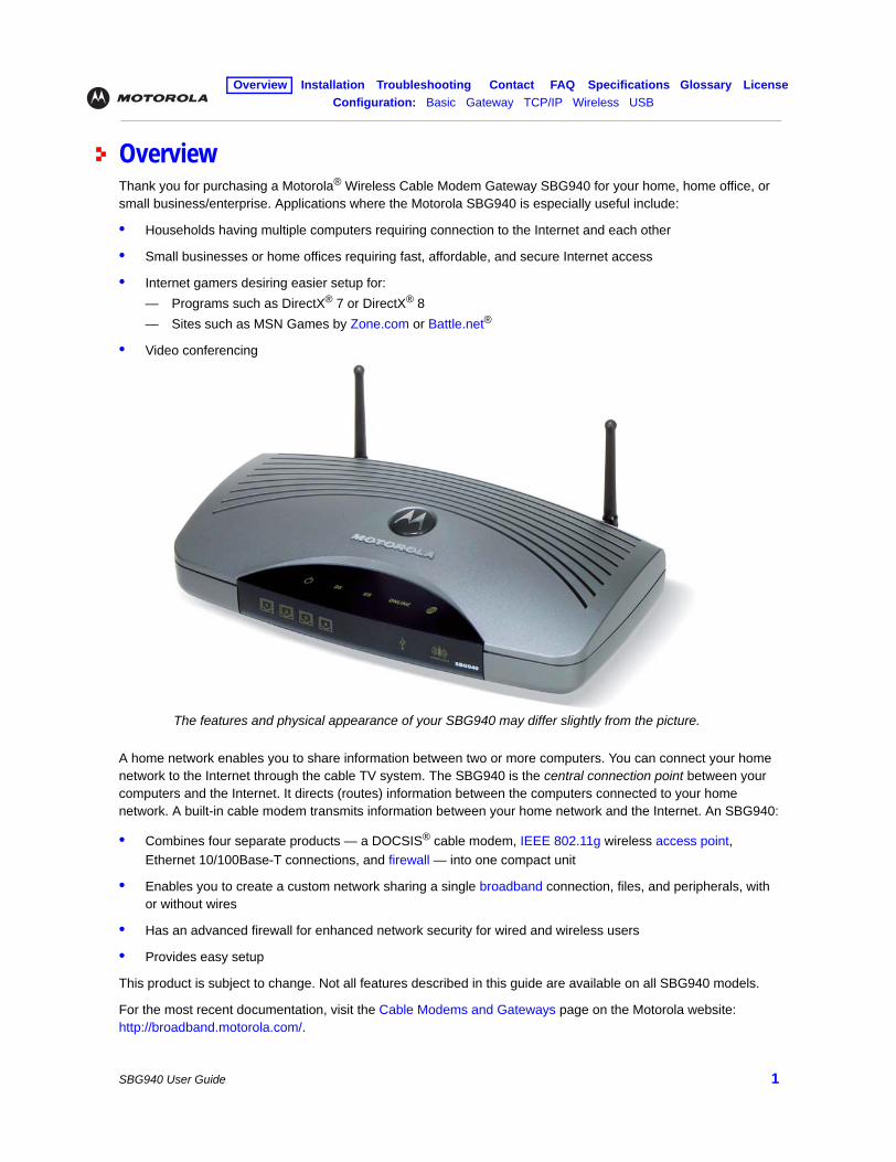
OverviewThank you for purchasing a Motorola® Wireless Cable Modem Gateway SBG940 for your home, home office, or small business/enterprise. Applications where the Motorola SBG940 is especially useful include:
• Households having multiple computers requiring connection to the Internet and each other
• Small businesses or home offices requiring fast, affordable, and secure Internet access
• Internet gamers desiring easier setup for:— Programs such as DirectX® 7 or DirectX® 8— Sites such as MSN Games by Zone.com or Battle.net®
• Video conferencing
A home network enables you to share information between two or more computers. You can connect your home network to the Internet through the cable TV system. The SBG940 is the central connection point between your computers and the Internet. It directs (routes) information between the computers connected to your home network. A built-in cable modem transmits information between your home network and the Internet. An SBG940:
• Combines four separate products — a DOCSIS® cable modem, IEEE 802.11g wireless access point, Ethernet 10/100Base-T connections, and firewall — into one compact unit
• Enables you to create a custom network sharing a single broadband connection, files, and peripherals, with or without wires
• Has an advanced firewall for enhanced network security for wired and wireless users
• Provides easy setup
This product is subject to change. Not all features described in this guide are available on all SBG940 models.
For the most recent documentation, visit the Cable Modems and Gateways page on the Motorola website: http://broadband.motorola.com/.
The features and physical appearance of your SBG940 may differ slightly from the picture.
Overview Installation Troubleshooting Contact FAQ Specifications Glossary LicenseConfiguration: Basic Gateway TCP/IP Wireless USB
SBG940 User Guide 2
Easy SetupIt is much easier to configure a local area network (LAN) using an SBG940 than using traditional networking equipment:
• The Installation Assistant application on the SBG940 Installation CD-ROM enables easy connection to the cable network.
• For basic operation, most default settings require no modification.
• The Setup Program provides a graphical user interface (GUI) for easy configuration of necessary wireless, Ethernet, router, DHCP, and security settings. For information about using the Setup Program, see “Basic Configuration”.
Network Connection TypesThe SBG940 provides different network connection types for your computers to exchange data. The connection between your computers and the SBG940 may be with a wireless or a wired connection or a combination of the two. Your network can use one or any combination of all the following network connections:
• Ethernet local area network (LAN)
• Wireless LAN (IEEE 802.11g that also supports IEEE 802.11b wireless clients)
• Universal Serial Bus (USB)
Overview Installation Troubleshooting Contact FAQ Specifications Glossary LicenseConfiguration: Basic Gateway TCP/IP Wireless USB
SBG940 User Guide 3
Powerful Features in a Single UnitAn SBG940 combines high-speed Internet access, networking, and computer security for a home or small-office LAN. An SBG940 provides:
• An integrated high-speed cable modem for continuous broadband access to the Internet and other online services with much faster data transfer than traditional dial-up or ISDN modems
• A single broadband connection for up to 253 computers to surf the web; all computers on the LAN communicate as if they were connected to the same physical network
• An IEEE 802.11g wireless access point to enable laptop users to remain connected while moving around the home or small office or to connect desktop computers without installing network wiring. Depending on distance, wireless connection speeds can match that of Ethernet.
• A USB connection for a single PC
• Four 10/100Base-T Ethernet uplink ports supporting half- or full-duplex connections and Auto-MDIX
• Routing for a wireless LAN (WLAN) or a wired Ethernet LAN; you can connect more than four computers using hubs and/or switches
• A built-in DHCP server to easily configure a combined wired and/or wireless Class C private LAN
• An advanced firewall supporting stateful-inspection, intrusion detection, DMZ, denial-of-service attack prevention, and Network Address Translation (NAT)
• Virtual private network (VPN) pass-through operation supporting IPSec, PPTP, or L2TP to securely connect remote computers over the Internet
• Port Forwarding to configure ports to run applications having special network requirements
Overview Installation Troubleshooting Contact FAQ Specifications Glossary LicenseConfiguration: Basic Gateway TCP/IP Wireless USB
SBG940 User Guide 4
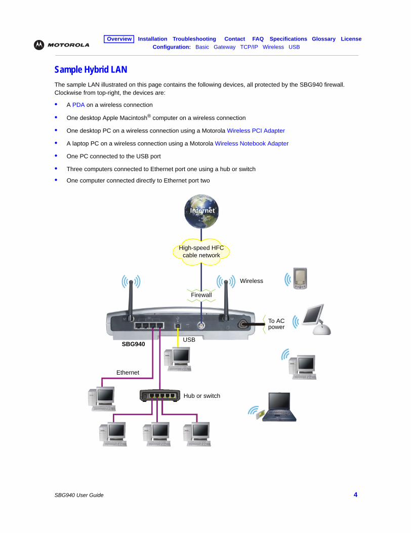
Sample Hybrid LANThe sample LAN illustrated on this page contains the following devices, all protected by the SBG940 firewall. Clockwise from top-right, the devices are:
• A PDA on a wireless connection
• One desktop Apple Macintosh® computer on a wireless connection
• One desktop PC on a wireless connection using a Motorola Wireless PCI Adapter
• A laptop PC on a wireless connection using a Motorola Wireless Notebook Adapter
• One PC connected to the USB port
• Three computers connected to Ethernet port one using a hub or switch
• One computer connected directly to Ethernet port two
Internet
High-speed HFC cable network
Wireless
Firewall
Ethernet
Hub or switch
SBG940USB
To AC power
Overview Installation Troubleshooting Contact FAQ Specifications Glossary LicenseConfiguration: Basic Gateway TCP/IP Wireless USB
SBG940 User Guide 5
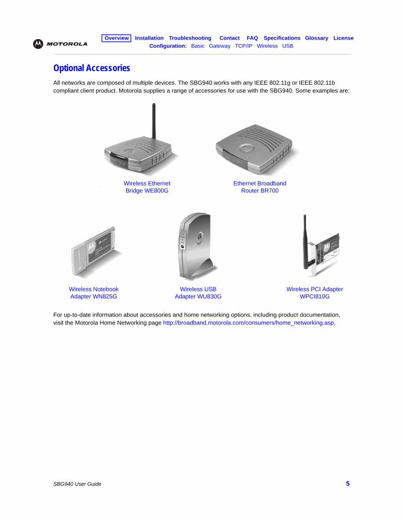
Optional AccessoriesAll networks are composed of multiple devices. The SBG940 works with any IEEE 802.11g or IEEE 802.11b compliant client product. Motorola supplies a range of accessories for use with the SBG940. Some examples are:
For up-to-date information about accessories and home networking options, including product documentation, visit the Motorola Home Networking page http://broadband.motorola.com/consumers/home_networking.asp.
Wireless Ethernet Bridge WE800G
Ethernet Broadband Router BR700
Wireless Notebook Adapter WN825G
Wireless PCI Adapter WPCI810G
Wireless USB Adapter WU830G
Overview Installation Troubleshooting Contact FAQ Specifications Glossary LicenseConfiguration: Basic Gateway TCP/IP Wireless USB
SBG940 User Guide 6
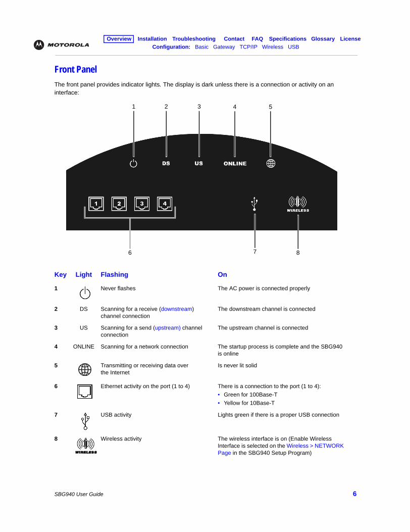
Front PanelThe front panel provides indicator lights. The display is dark unless there is a connection or activity on an interface:
Key Light Flashing On
1 Never flashes The AC power is connected properly
2 DS Scanning for a receive (downstream) channel connection
The downstream channel is connected
3 US Scanning for a send (upstream) channel connection
The upstream channel is connected
4 ONLINE Scanning for a network connection The startup process is complete and the SBG940 is online
5 Transmitting or receiving data over the Internet
Is never lit solid
6 Ethernet activity on the port (1 to 4) There is a connection to the port (1 to 4):• Green for 100Base-T• Yellow for 10Base-T
7 USB activity Lights green if there is a proper USB connection
8 Wireless activity The wireless interface is on (Enable Wireless Interface is selected on the Wireless > NETWORK Page in the SBG940 Setup Program)
1 2 3 4
6 8
5
7
Overview Installation Troubleshooting Contact FAQ Specifications Glossary LicenseConfiguration: Basic Gateway TCP/IP Wireless USB
SBG940 User Guide 7
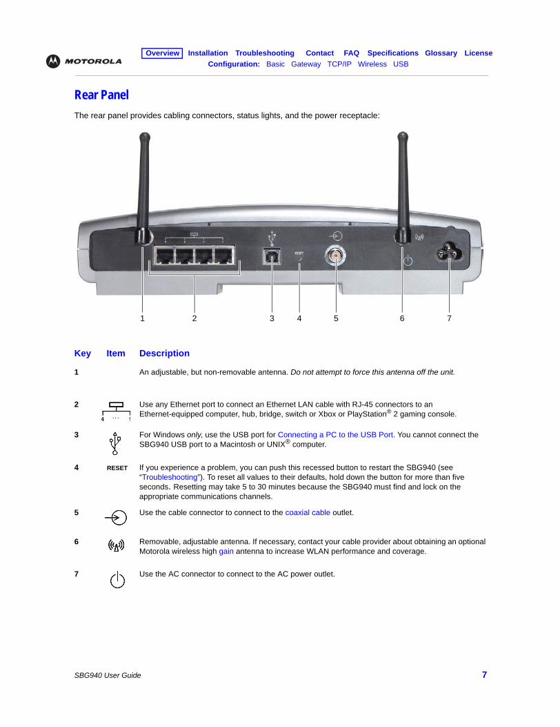
Rear PanelThe rear panel provides cabling connectors, status lights, and the power receptacle:
Key Item Description
1 An adjustable, but non-removable antenna. Do not attempt to force this antenna off the unit.
2 Use any Ethernet port to connect an Ethernet LAN cable with RJ-45 connectors to an Ethernet-equipped computer, hub, bridge, switch or Xbox or PlayStation® 2 gaming console.
3 For Windows only, use the USB port for Connecting a PC to the USB Port. You cannot connect the SBG940 USB port to a Macintosh or UNIX® computer.
4 RESET If you experience a problem, you can push this recessed button to restart the SBG940 (see “Troubleshooting”). To reset all values to their defaults, hold down the button for more than five seconds. Resetting may take 5 to 30 minutes because the SBG940 must find and lock on the appropriate communications channels.
5 Use the cable connector to connect to the coaxial cable outlet.
6 Removable, adjustable antenna. If necessary, contact your cable provider about obtaining an optional Motorola wireless high gain antenna to increase WLAN performance and coverage.
7 Use the AC connector to connect to the AC power outlet.
2 3 4 5 6 71
Overview Installation Troubleshooting Contact FAQ Specifications Glossary LicenseConfiguration: Basic Gateway TCP/IP Wireless USB
SBG940 User Guide 8
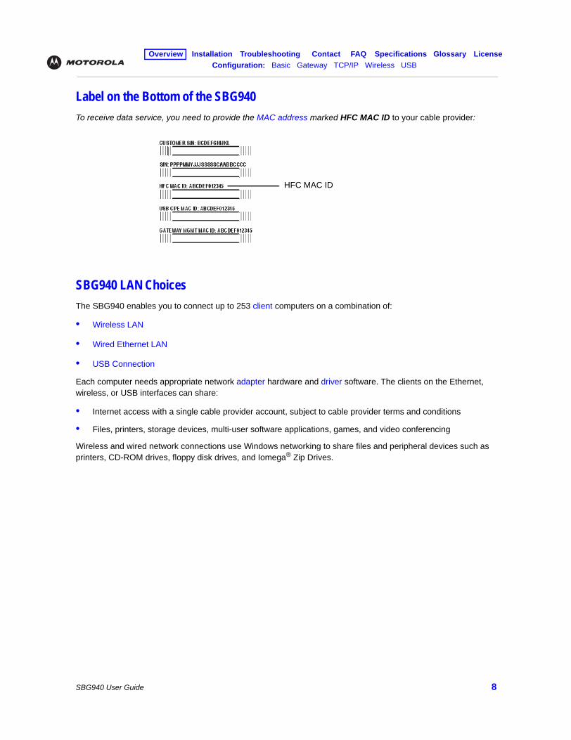
Label on the Bottom of the SBG940To receive data service, you need to provide the MAC address marked HFC MAC ID to your cable provider:
SBG940 LAN ChoicesThe SBG940 enables you to connect up to 253 client computers on a combination of:
• Wireless LAN
• Wired Ethernet LAN
• USB Connection
Each computer needs appropriate network adapter hardware and driver software. The clients on the Ethernet, wireless, or USB interfaces can share:
• Internet access with a single cable provider account, subject to cable provider terms and conditions
• Files, printers, storage devices, multi-user software applications, games, and video conferencing
Wireless and wired network connections use Windows networking to share files and peripheral devices such as printers, CD-ROM drives, floppy disk drives, and Iomega® Zip Drives.
HFC MAC ID
Overview Installation Troubleshooting Contact FAQ Specifications Glossary LicenseConfiguration: Basic Gateway TCP/IP Wireless USB
SBG940 User Guide 9
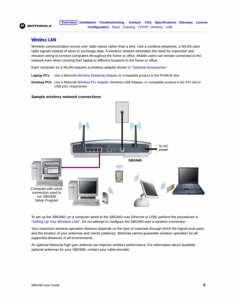
Wireless LANWireless communication occurs over radio waves rather than a wire. Like a cordless telephone, a WLAN uses radio signals instead of wires to exchange data. A wireless network eliminates the need for expensive and intrusive wiring to connect computers throughout the home or office. Mobile users can remain connected to the network even when carrying their laptop to different locations in the home or office.
Each computer on a WLAN requires a wireless adapter shown in “Optional Accessories”:
Sample wireless network connections
To set up the SBG940, on a computer wired to the SBG940 over Ethernet or USB, perform the procedures in “Setting Up Your Wireless LAN”. Do not attempt to configure the SBG940 over a wireless connection.
Your maximum wireless operation distance depends on the type of materials through which the signal must pass and the location of your antennas and clients (stations). Motorola cannot guarantee wireless operation for all supported distances in all environments.
An optional Motorola high gain antenna can improve wireless performance. For information about available optional antennas for your SBG940, contact your cable provider.
Laptop PCs Use a Motorola Wireless Notebook Adapter or compatible product in the PCMCIA slot.
Desktop PCs Use a Motorola Wireless PCI Adapter, Wireless USB Adapter, or compatible product in the PCI slot or USB port, respectively.
Computer with wired connection used to
run SBG940 Setup Program
SBG940
To AC power
Overview Installation Troubleshooting Contact FAQ Specifications Glossary LicenseConfiguration: Basic Gateway TCP/IP Wireless USB
SBG940 User Guide 10
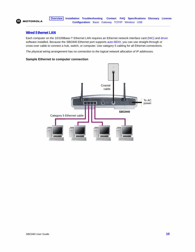
Wired Ethernet LANEach computer on the 10/100Base-T Ethernet LAN requires an Ethernet network interface card (NIC) and driver software installed. Because the SBG940 Ethernet port supports auto-MDIX, you can use straight-through or cross-over cable to connect a hub, switch, or computer. Use category 5 cabling for all Ethernet connections.
The physical wiring arrangement has no connection to the logical network allocation of IP addresses.
Sample Ethernet to computer connection
Coaxialcable
Category 5 Ethernet cableSBG940
To AC power
Overview Installation Troubleshooting Contact FAQ Specifications Glossary LicenseConfiguration: Basic Gateway TCP/IP Wireless USB
SBG940 User Guide 11
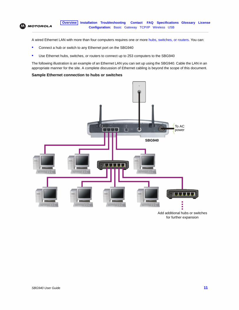
A wired Ethernet LAN with more than four computers requires one or more hubs, switches, or routers. You can:
• Connect a hub or switch to any Ethernet port on the SBG940
• Use Ethernet hubs, switches, or routers to connect up to 253 computers to the SBG940
The following illustration is an example of an Ethernet LAN you can set up using the SBG940. Cable the LAN in an appropriate manner for the site. A complete discussion of Ethernet cabling is beyond the scope of this document.
Sample Ethernet connection to hubs or switches
Add additional hubs or switches for further expansion
SBG940
To AC power
Overview Installation Troubleshooting Contact FAQ Specifications Glossary LicenseConfiguration: Basic Gateway TCP/IP Wireless USB
SBG940 User Guide 12
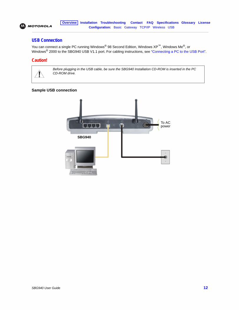
USB ConnectionYou can connect a single PC running Windows® 98 Second Edition, Windows XP™, Windows Me®, or Windows® 2000 to the SBG940 USB V1.1 port. For cabling instructions, see “Connecting a PC to the USB Port”.
Sample USB connection
Caution!
Before plugging in the USB cable, be sure the SBG940 Installation CD-ROM is inserted in the PC CD-ROM drive.
SBG940
To AC power
Overview Installation Troubleshooting Contact FAQ Specifications Glossary LicenseConfiguration: Basic Gateway TCP/IP Wireless USB
SBG940 User Guide 13
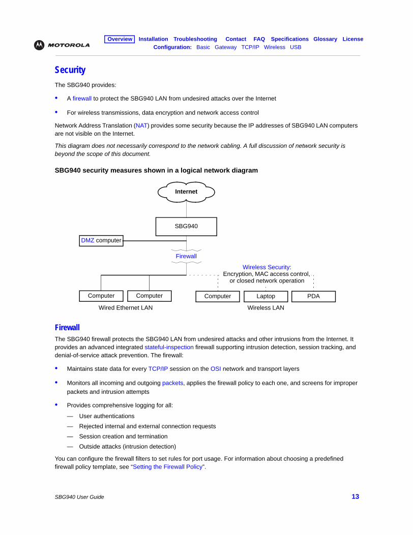
SecurityThe SBG940 provides:
• A firewall to protect the SBG940 LAN from undesired attacks over the Internet
• For wireless transmissions, data encryption and network access control
Network Address Translation (NAT) provides some security because the IP addresses of SBG940 LAN computers are not visible on the Internet.
This diagram does not necessarily correspond to the network cabling. A full discussion of network security is beyond the scope of this document.
SBG940 security measures shown in a logical network diagram
FirewallThe SBG940 firewall protects the SBG940 LAN from undesired attacks and other intrusions from the Internet. It provides an advanced integrated stateful-inspection firewall supporting intrusion detection, session tracking, and denial-of-service attack prevention. The firewall:
• Maintains state data for every TCP/IP session on the OSI network and transport layers
• Monitors all incoming and outgoing packets, applies the firewall policy to each one, and screens for improper packets and intrusion attempts
• Provides comprehensive logging for all:
— User authentications— Rejected internal and external connection requests— Session creation and termination— Outside attacks (intrusion detection)
You can configure the firewall filters to set rules for port usage. For information about choosing a predefined firewall policy template, see “Setting the Firewall Policy”.
SBG940
Firewall
ComputerComputer
Wired Ethernet LAN Wireless LAN
LaptopComputer PDA
Wireless Security:Encryption, MAC access control,
or closed network operation
Internet
DMZ computer
Overview Installation Troubleshooting Contact FAQ Specifications Glossary LicenseConfiguration: Basic Gateway TCP/IP Wireless USB
SBG940 User Guide 14
DMZA de-militarized zone (DMZ) is one or more computers logically located outside the firewall between an SBG940 LAN and the Internet. A DMZ prevents direct access by outside users to private data.
For example, you can set up a web server on a DMZ computer to enable outside users to access your website without exposing confidential data on your network.
A DMZ can also be useful to play interactive games that may have a problem running through a firewall. You can leave a computer used for gaming only exposed to the Internet while protecting the rest of your network. For more information, see “Gaming Configuration Guidelines”.
Port TriggeringWhen you run an application that accesses the Internet, it typically initiates communications with a computer on the Internet. For some applications, especially gaming, the computer on the Internet also initiates communications with your computer. Because NAT does not normally allow these incoming connections:
• The SBG940 has preconfigured port triggers for common applications.
• If needed, you can configure additional port triggers on the Gateway > PORT TRIGGERS — custom Page.
Wireless SecurityBecause WLAN data is transmitted using radio signals, it may be possible for an unauthorized person to access your WLAN unless you prevent them from doing so. To prevent unauthorized eavesdropping of data transmitted over your LAN, you must enable wireless security. The default SBG940 settings neither provide security for transmitted data nor protect network data from unauthorized intrusions.
The SBG940 provides the following wireless security measures, which are described in “Setting Up Your Wireless LAN”:
• To prevent unauthorized eavesdropping, you must encrypt data transmitted over the wireless interface using one of:
— If all of your wireless clients support Wi-Fi® Protected Access (WPA) encryption, we recommend using WPA (see “Configuring WPA on the SBG940” and “Configuring a Wireless Client for WPA”).
— Otherwise, configure a Wired Equivalency Privacy (WEP) key on the SBG940 and each WLAN client (see “Configuring WEP on the SBG940” and “Configuring a Wireless Client for WEP”).
• To protect LAN data from unauthorized intrusions, you can restrict WLAN access to computers having one or both of:
— Known MAC addresses (see “Configuring a MAC Access Control List on the SBG940”)
— The same unique network name (ESSID) as the SBG940 (see “Configuring the Wireless Network Name on the SBG940” and “Configuring a Wireless Client with the Network Name (ESSID)”)
Restricting access to computers having the same network name is also called “disabling ESSID broadcasting” or “enabling closed network operation.”
Overview Installation Troubleshooting Contact FAQ Specifications Glossary LicenseConfiguration: Basic Gateway TCP/IP Wireless USB
SBG940 User Guide 15
Port ForwardingThe SBG940 opens logical data ports when a computer on its LAN sends data, such as e-mail messages or web data, to the Internet. A logical data port is different from a physical port, such as an Ethernet port. Data from a protocol must go through certain data ports.
Some applications, such as games and videoconferencing, require multiple data ports. If you enable NAT, this can cause problems because NAT assumes that data sent through one port will return to the same port. You may need to configure port forwarding to run applications with special requirements.
To configure port forwarding, you must specify an inbound (source) port or range of ports. The inbound port opens only when data is sent to the inbound port and closes again after a specified time elapses with no data sent to it. You can configure up to 32 port forwarding entries using the Gateway > PORT FORWARDING — config Page.
Virtual Private NetworksThe SBG940 supports multiple tunnel VPN pass-through operation to securely connect remote computers over the Internet. The SBG940:
• Is compatible with Point to Point Tunneling Protocol (PPTP) and Layer 2 Tunneling Protocol (L2TP)
• Is fully interoperable with any IPSec client or gateway and ANX certified IPSec stacks
Related DocumentationThe SBG940 Quick Installation Guide also provides information about using the SBG940.
For information about and documentation for Motorola home-networking products, visit the Motorola Home Networking page http://broadband.motorola.com/consumers/home_networking.asp.
Overview Installation Troubleshooting Contact FAQ Specifications Glossary LicenseConfiguration: Basic Gateway TCP/IP Wireless USB
SBG940 User Guide 16
InstallationThe following subsections provide information about installing the SBG940 hardware:• Before You Begin
• Precautions
• Signing Up for Service
• Computer System Requirements
• Connecting the SBG940 to the Cable System
• Cabling the LAN
• Obtaining an IP Address for Ethernet
• Connecting a PC to the USB Port
• Wall Mounting
For information about WLAN setup, see “Setting Up Your Wireless LAN”.
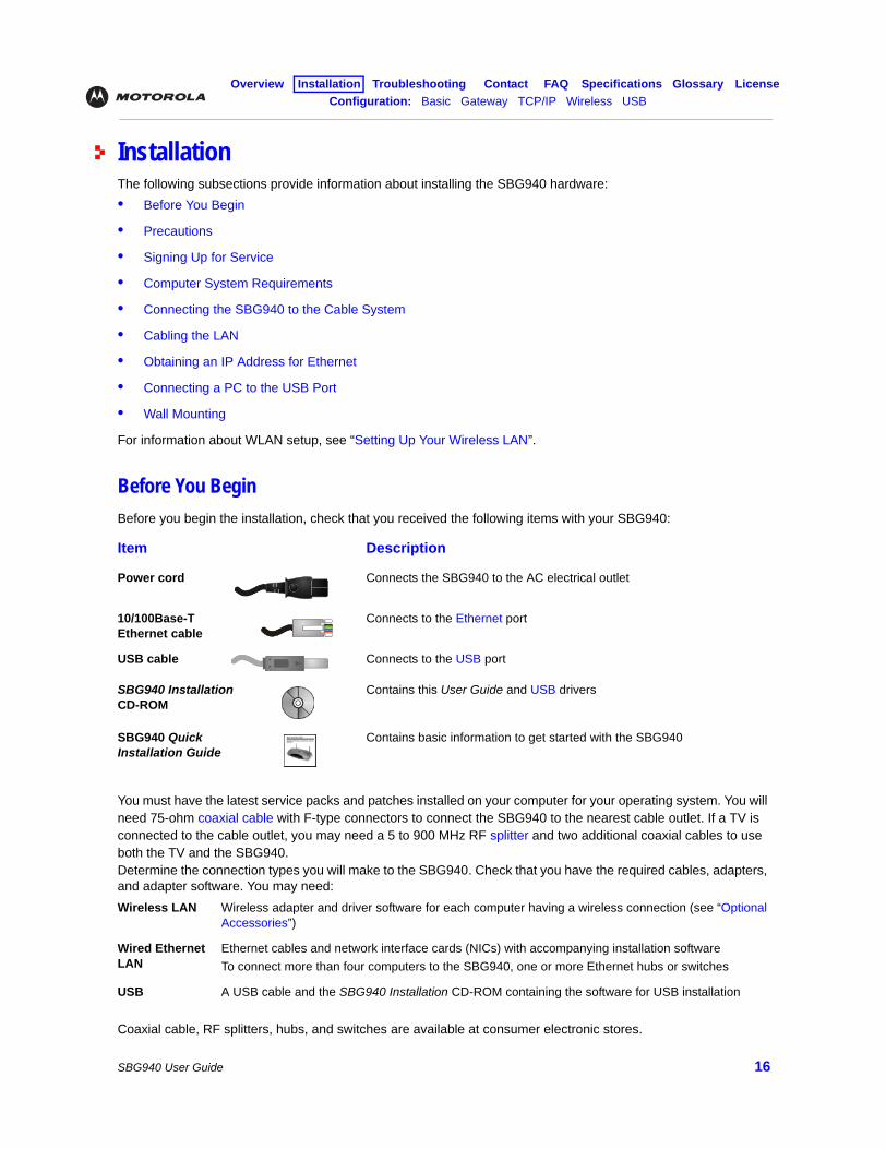
Before You BeginBefore you begin the installation, check that you received the following items with your SBG940:
You must have the latest service packs and patches installed on your computer for your operating system. You will need 75-ohm coaxial cable with F-type connectors to connect the SBG940 to the nearest cable outlet. If a TV is connected to the cable outlet, you may need a 5 to 900 MHz RF splitter and two additional coaxial cables to use both the TV and the SBG940.Determine the connection types you will make to the SBG940. Check that you have the required cables, adapters, and adapter software. You may need:
Coaxial cable, RF splitters, hubs, and switches are available at consumer electronic stores.
Item Description
Power cord Connects the SBG940 to the AC electrical outlet
10/100Base-T Ethernet cable
Connects to the Ethernet port
USB cable Connects to the USB port
SBG940 Installation CD-ROM
Contains this User Guide and USB drivers
SBG940 Quick Installation Guide
Contains basic information to get started with the SBG940
Wireless LAN Wireless adapter and driver software for each computer having a wireless connection (see “Optional Accessories”)
Wired Ethernet LAN
Ethernet cables and network interface cards (NICs) with accompanying installation softwareTo connect more than four computers to the SBG940, one or more Ethernet hubs or switches
USB A USB cable and the SBG940 Installation CD-ROM containing the software for USB installation
Overview Installation Troubleshooting Contact FAQ Specifications Glossary LicenseConfiguration: Basic Gateway TCP/IP Wireless USB
SBG940 User Guide 17
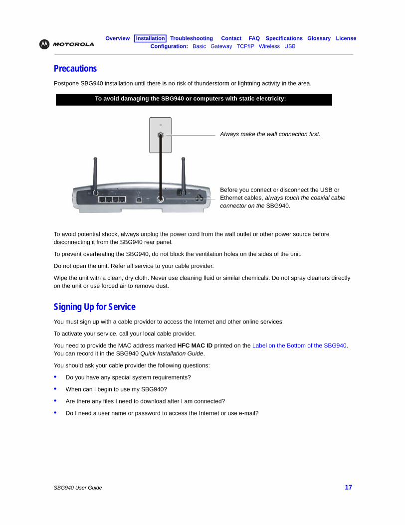
PrecautionsPostpone SBG940 installation until there is no risk of thunderstorm or lightning activity in the area.
To avoid potential shock, always unplug the power cord from the wall outlet or other power source before disconnecting it from the SBG940 rear panel.
To prevent overheating the SBG940, do not block the ventilation holes on the sides of the unit.
Do not open the unit. Refer all service to your cable provider.
Wipe the unit with a clean, dry cloth. Never use cleaning fluid or similar chemicals. Do not spray cleaners directly on the unit or use forced air to remove dust.
Signing Up for ServiceYou must sign up with a cable provider to access the Internet and other online services.
To activate your service, call your local cable provider.
You need to provide the MAC address marked HFC MAC ID printed on the Label on the Bottom of the SBG940. You can record it in the SBG940 Quick Installation Guide.
You should ask your cable provider the following questions:
• Do you have any special system requirements?
• When can I begin to use my SBG940?
• Are there any files I need to download after I am connected?
• Do I need a user name or password to access the Internet or use e-mail?
To avoid damaging the SBG940 or computers with static electricity:
Always make the wall connection first.
Before you connect or disconnect the USB or Ethernet cables, always touch the coaxial cable connector on the SBG940.
Overview Installation Troubleshooting Contact FAQ Specifications Glossary LicenseConfiguration: Basic Gateway TCP/IP Wireless USB
SBG940 User Guide 18
Computer System RequirementsYou can connect Microsoft Windows, Macintosh, UNIX®, or Linux® computers equipped as follows to the SBG940 LAN:
• One of the following:
• PC with Pentium class or better processor
• Windows® 98, Windows® 98 SE, Windows Me®, Windows® 2000, Windows XPTM, Windows NT®, Macintosh, or Linux® operating system with operating system CD-ROM available.
• Minimum 16 MB RAM recommended
• 10 MB available hard disk space
You can use any web browser such as Microsoft® Internet Explorer or Netscape Navigator® with the SBG940.
Windows® 95 is not supported by the SBG940.
Windows 98, Windows NT, UNIX, Linux, or Macintosh computers must use the Ethernet connection.
You can use the USB connection with any PC running Windows 98 Second Edition, Windows 2000, Windows Me, or Windows XP that has a USB interface. The USB connection requires special USB driver software that is supplied on the SBG940 Installation CD-ROM. You can upgrade your USB drivers from the Motorola Downloads page http://broadband.motorola.com/noflash/usb_drivers.asp.
Ethernet 10Base-T or 10/100Base-T Ethernet adapter with proper driver software installed.
Wireless Any IEEE 802.11g or IEEE 802.11b device. For information about the Motorola WN825G Wireless Card (PCMCIA type II 3.3 V slot) or WPCI810G Wireless Adapter, see “Optional Accessories”.
Overview Installation Troubleshooting Contact FAQ Specifications Glossary LicenseConfiguration: Basic Gateway TCP/IP Wireless USB
SBG940 User Guide 19
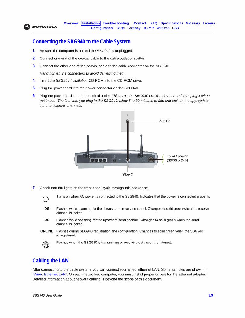
Connecting the SBG940 to the Cable System1 Be sure the computer is on and the SBG940 is unplugged.
2 Connect one end of the coaxial cable to the cable outlet or splitter.
3 Connect the other end of the coaxial cable to the cable connector on the SBG940.
Hand-tighten the connectors to avoid damaging them.
4 Insert the SBG940 Installation CD-ROM into the CD-ROM drive.
5 Plug the power cord into the power connector on the SBG940.
6 Plug the power cord into the electrical outlet. This turns the SBG940 on. You do not need to unplug it when not in use. The first time you plug in the SBG940, allow 5 to 30 minutes to find and lock on the appropriate communications channels.
7 Check that the lights on the front panel cycle through this sequence:
Cabling the LANAfter connecting to the cable system, you can connect your wired Ethernet LAN. Some samples are shown in “Wired Ethernet LAN”. On each networked computer, you must install proper drivers for the Ethernet adapter. Detailed information about network cabling is beyond the scope of this document.
Turns on when AC power is connected to the SBG940. Indicates that the power is connected properly.
DS Flashes while scanning for the downstream receive channel. Changes to solid green when the receive channel is locked.
US Flashes while scanning for the upstream send channel. Changes to solid green when the send channel is locked.
ONLINE Flashes during SBG940 registration and configuration. Changes to solid green when the SBG940 is registered.
Flashes when the SBG940 is transmitting or receiving data over the Internet.
Step 2
Step 3
To AC power (steps 5 to 6)
Overview Installation Troubleshooting Contact FAQ Specifications Glossary LicenseConfiguration: Basic Gateway TCP/IP Wireless USB
SBG940 User Guide 20
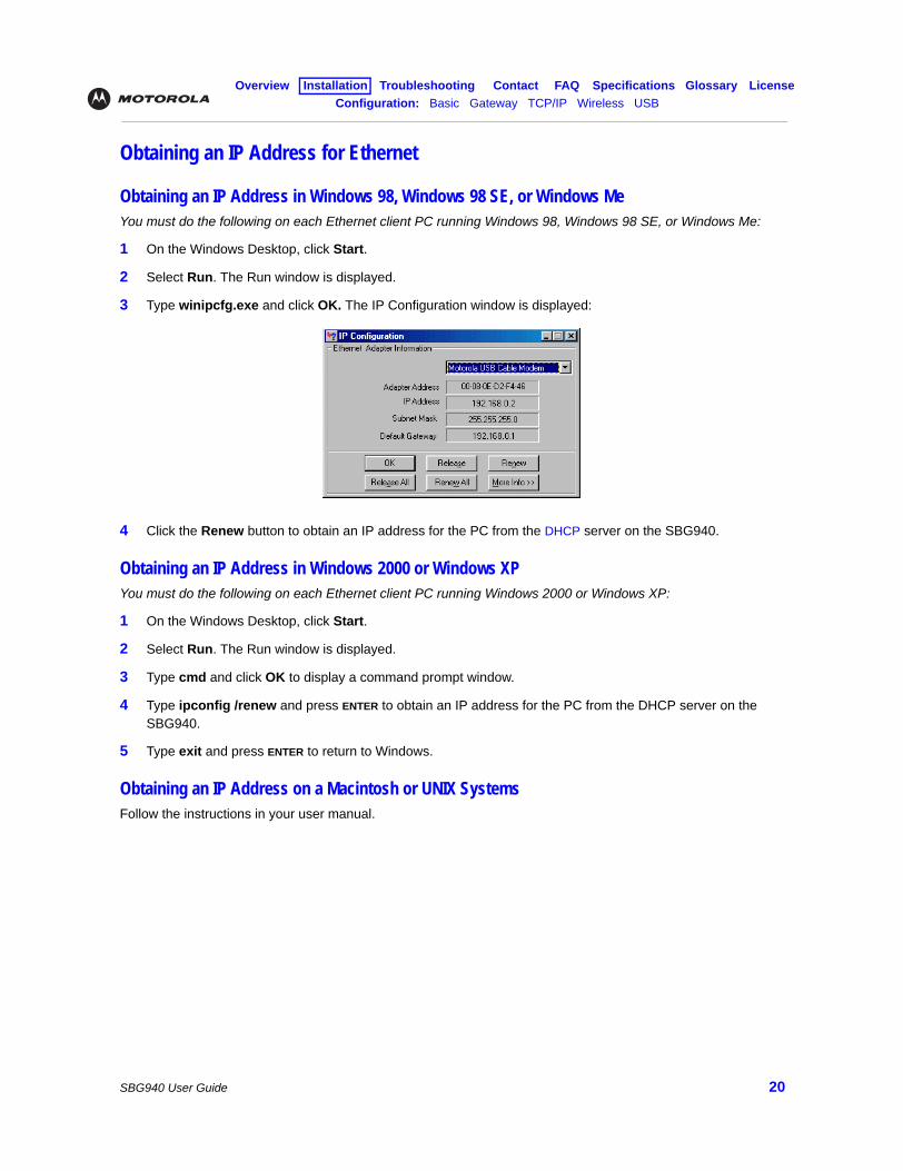
Obtaining an IP Address for Ethernet
Obtaining an IP Address in Windows 98, Windows 98 SE, or Windows MeYou must do the following on each Ethernet client PC running Windows 98, Windows 98 SE, or Windows Me:
1 On the Windows Desktop, click Start.
2 Select Run. The Run window is displayed.
3 Type winipcfg.exe and click OK. The IP Configuration window is displayed:
4 Click the Renew button to obtain an IP address for the PC from the DHCP server on the SBG940.
Obtaining an IP Address in Windows 2000 or Windows XPYou must do the following on each Ethernet client PC running Windows 2000 or Windows XP:
1 On the Windows Desktop, click Start.
2 Select Run. The Run window is displayed.
3 Type cmd and click OK to display a command prompt window.
4 Type ipconfig /renew and press ENTER to obtain an IP address for the PC from the DHCP server on the SBG940.
5 Type exit and press ENTER to return to Windows.
Obtaining an IP Address on a Macintosh or UNIX SystemsFollow the instructions in your user manual.
Overview Installation Troubleshooting Contact FAQ Specifications Glossary LicenseConfiguration: Basic Gateway TCP/IP Wireless USB
SBG940 User Guide 21
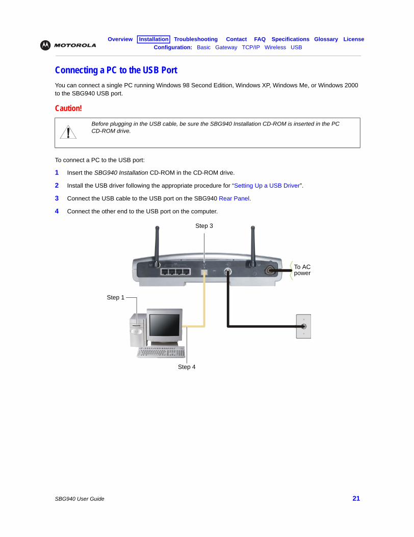
Connecting a PC to the USB PortYou can connect a single PC running Windows 98 Second Edition, Windows XP, Windows Me, or Windows 2000 to the SBG940 USB port.
To connect a PC to the USB port:
1 Insert the SBG940 Installation CD-ROM in the CD-ROM drive.
2 Install the USB driver following the appropriate procedure for “Setting Up a USB Driver”.
3 Connect the USB cable to the USB port on the SBG940 Rear Panel.
4 Connect the other end to the USB port on the computer.
Caution!
Before plugging in the USB cable, be sure the SBG940 Installation CD-ROM is inserted in the PC CD-ROM drive.
Step 3
Step 4
To AC power
Step 1
Overview Installation Troubleshooting Contact FAQ Specifications Glossary LicenseConfiguration: Basic Gateway TCP/IP Wireless USB
SBG940 User Guide 22
Wall MountingIf you mount the unit on the wall, you must:
• Locate the unit as specified by the local or national codes governing residential or business cable TV and communications services.
• Follow all local standards for installing a network interface unit/network interface device (NIU/NID).
If possible, mount the unit to concrete, masonry, a wooden stud, or other very solid wall material. Use anchors if necessary; for example, if you must mount the unit on drywall.
To mount your SBG940 on the wall:
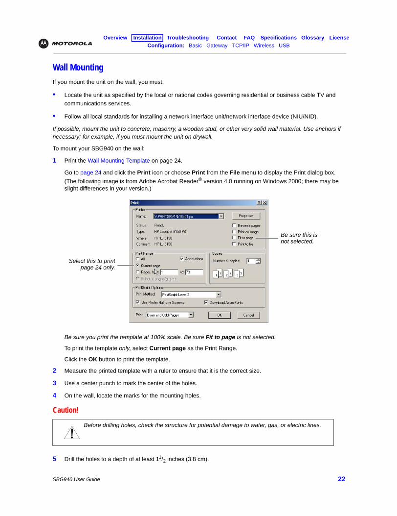
1 Print the Wall Mounting Template on page 24.
Go to page 24 and click the Print icon or choose Print from the File menu to display the Print dialog box. (The following image is from Adobe Acrobat Reader® version 4.0 running on Windows 2000; there may be slight differences in your version.)
Be sure you print the template at 100% scale. Be sure Fit to page is not selected.
To print the template only, select Current page as the Print Range.
Click the OK button to print the template.
2 Measure the printed template with a ruler to ensure that it is the correct size.
3 Use a center punch to mark the center of the holes.
4 On the wall, locate the marks for the mounting holes.
5 Drill the holes to a depth of at least 11/2 inches (3.8 cm).
Caution!
Before drilling holes, check the structure for potential damage to water, gas, or electric lines.
Be sure this is not selected.
Select this to printpage 24 only.
Overview Installation Troubleshooting Contact FAQ Specifications Glossary LicenseConfiguration: Basic Gateway TCP/IP Wireless USB
SBG940 User Guide 23
6 If necessary, seat an anchor in each hole.
Use M5 x 38 mm (#10-16 x 11/2 inch) screws with a flat underside and maximum screw head diameter of 10.5 mm to mount the SBG940.
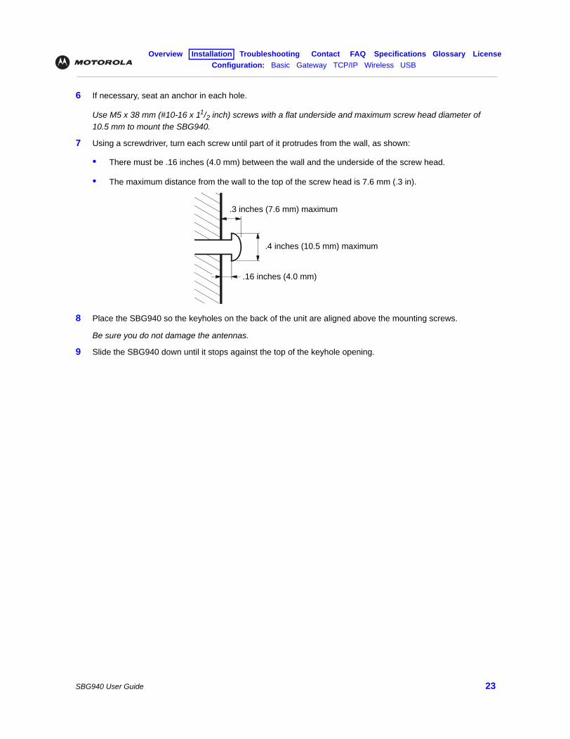
7 Using a screwdriver, turn each screw until part of it protrudes from the wall, as shown:
• There must be .16 inches (4.0 mm) between the wall and the underside of the screw head.
• The maximum distance from the wall to the top of the screw head is 7.6 mm (.3 in).
8 Place the SBG940 so the keyholes on the back of the unit are aligned above the mounting screws.
Be sure you do not damage the antennas.
9 Slide the SBG940 down until it stops against the top of the keyhole opening.
.3 inches (7.6 mm) maximum
.4 inches (10.5 mm) maximum
.16 inches (4.0 mm)
Overview Installation Troubleshooting Contact FAQ Specifications Glossary LicenseConfiguration: Basic Gateway TCP/IP Wireless USB
SBG940 User Guide 24
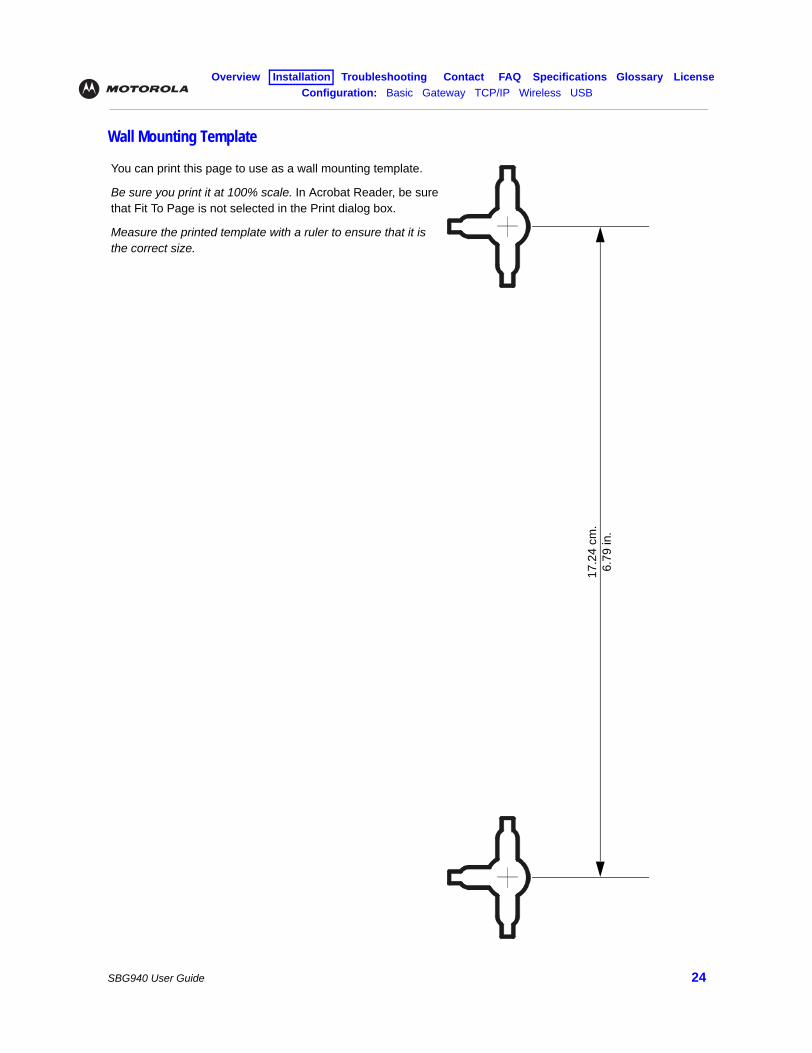
Wall Mounting Template
You can print this page to use as a wall mounting template.
Be sure you print it at 100% scale. In Acrobat Reader, be sure that Fit To Page is not selected in the Print dialog box.
Measure the printed template with a ruler to ensure that it is the correct size.
17.2
4 cm
.6.
79 in
.
Overview Installation Troubleshooting Contact FAQ Specifications Glossary LicenseConfiguration: Basic Gateway TCP/IP Wireless USB
SBG940 User Guide 25
Basic ConfigurationThe following sections provide information about basic SBG940 configuration:
• Starting the SBG940 Setup Program
• Changing the Default Password
• Getting Help
• Setting the Firewall Policy
• Gaming Configuration Guidelines
For more advanced configuration information, see “Configuring TCP/IP”, “Setting Up Your Wireless LAN”, or “Setting Up a USB Driver”.
For normal operation, you do not need to change most default settings. The following caution statements summarize the issues you must be aware of:
Caution!
To prevent unauthorized configuration, change the default password immediately when you first configure the SBG940. See “Changing the Default Password”.
Firewalls are not foolproof. Choose the most secure firewall policy you can. See “Setting the Firewall Policy”.
If you are using a wired LAN only and have no wireless clients, be sure you disable the wireless interface by turning off Enable Wireless Interface on the Wireless > NETWORK Page.
For a wireless LAN only, be sure you follow the instructions in “Setting Up Your Wireless LAN”.
Overview Installation Troubleshooting Contact FAQ Specifications Glossary LicenseConfiguration: Basic Gateway TCP/IP Wireless USB
SBG940 User Guide 26
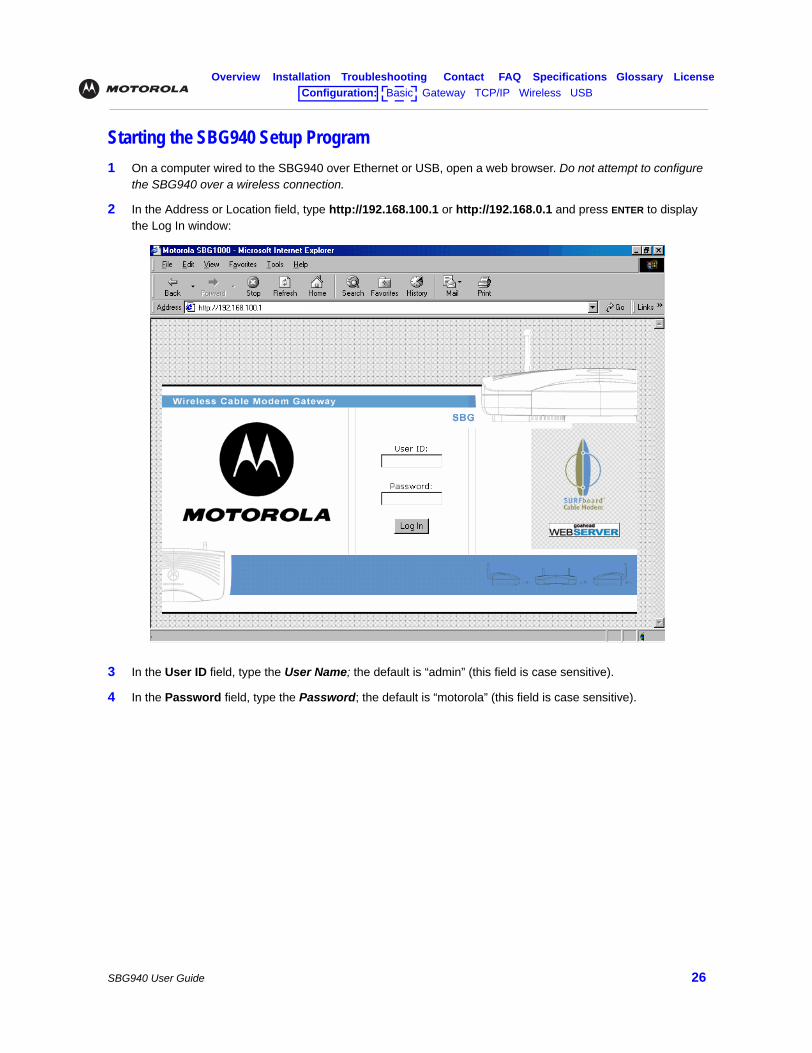
Starting the SBG940 Setup Program1 On a computer wired to the SBG940 over Ethernet or USB, open a web browser. Do not attempt to configure
the SBG940 over a wireless connection.
2 In the Address or Location field, type http://192.168.100.1 or http://192.168.0.1 and press ENTER to display the Log In window:
3 In the User ID field, type the User Name; the default is “admin” (this field is case sensitive).
4 In the Password field, type the Password; the default is “motorola” (this field is case sensitive).
Overview Installation Troubleshooting Contact FAQ Specifications Glossary LicenseConfiguration: Basic Gateway TCP/IP Wireless USB
SBG940 User Guide 27
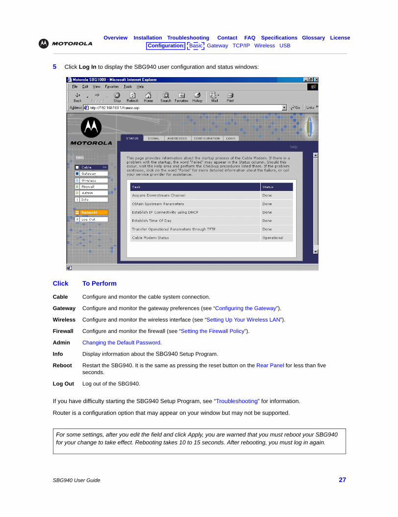
5 Click Log In to display the SBG940 user configuration and status windows:
If you have difficulty starting the SBG940 Setup Program, see “Troubleshooting” for information.
Router is a configuration option that may appear on your window but may not be supported.
Click To Perform
Cable Configure and monitor the cable system connection.
Gateway Configure and monitor the gateway preferences (see “Configuring the Gateway”).
Wireless Configure and monitor the wireless interface (see “Setting Up Your Wireless LAN”).
Firewall Configure and monitor the firewall (see “Setting the Firewall Policy”).
Admin Changing the Default Password.
Info Display information about the SBG940 Setup Program.
Reboot Restart the SBG940. It is the same as pressing the reset button on the Rear Panel for less than five seconds.
Log Out Log out of the SBG940.
For some settings, after you edit the field and click Apply, you are warned that you must reboot your SBG940 for your change to take effect. Rebooting takes 10 to 15 seconds. After rebooting, you must log in again.
Overview Installation Troubleshooting Contact FAQ Specifications Glossary LicenseConfiguration: Basic Gateway TCP/IP Wireless USB
SBG940 User Guide 28
Changing the Default Password
To change the default password:
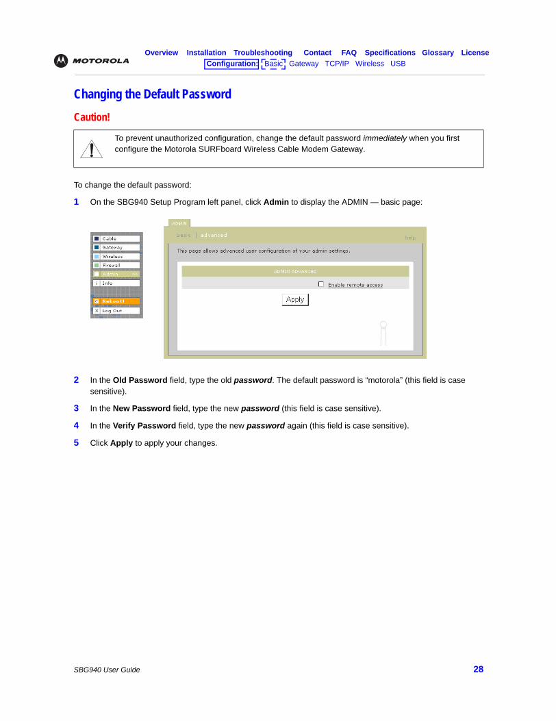
1 On the SBG940 Setup Program left panel, click Admin to display the ADMIN — basic page:
2 In the Old Password field, type the old password. The default password is “motorola” (this field is case sensitive).
3 In the New Password field, type the new password (this field is case sensitive).
4 In the Verify Password field, type the new password again (this field is case sensitive).
5 Click Apply to apply your changes.
Caution!
To prevent unauthorized configuration, change the default password immediately when you first configure the Motorola SURFboard Wireless Cable Modem Gateway.
Overview Installation Troubleshooting Contact FAQ Specifications Glossary LicenseConfiguration: Basic Gateway TCP/IP Wireless USB
SBG940 User Guide 29
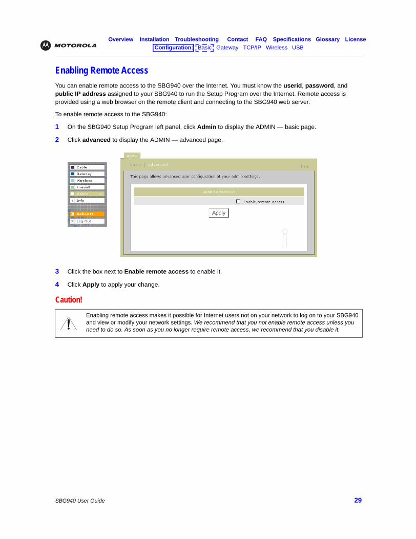
Enabling Remote AccessYou can enable remote access to the SBG940 over the Internet. You must know the userid, password, and public IP address assigned to your SBG940 to run the Setup Program over the Internet. Remote access is provided using a web browser on the remote client and connecting to the SBG940 web server.
To enable remote access to the SBG940:
1 On the SBG940 Setup Program left panel, click Admin to display the ADMIN — basic page.
2 Click advanced to display the ADMIN — advanced page.
3 Click the box next to Enable remote access to enable it.
4 Click Apply to apply your change.
Caution!
Enabling remote access makes it possible for Internet users not on your network to log on to your SBG940 and view or modify your network settings. We recommend that you not enable remote access unless you need to do so. As soon as you no longer require remote access, we recommend that you disable it.
Overview Installation Troubleshooting Contact FAQ Specifications Glossary LicenseConfiguration: Basic Gateway TCP/IP Wireless USB
SBG940 User Guide 30
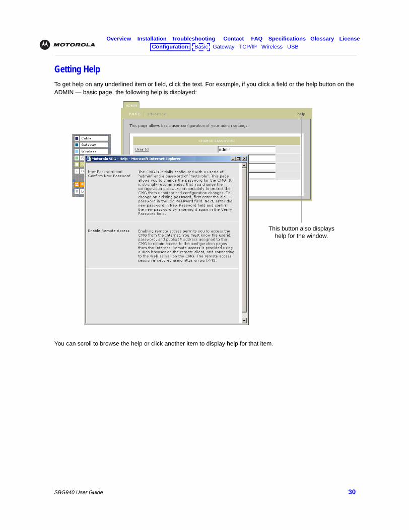
Getting HelpTo get help on any underlined item or field, click the text. For example, if you click a field or the help button on the ADMIN — basic page, the following help is displayed:
You can scroll to browse the help or click another item to display help for that item.
This button also displays help for the window.
Overview Installation Troubleshooting Contact FAQ Specifications Glossary LicenseConfiguration: Basic Gateway TCP/IP Wireless USB
SBG940 User Guide 31
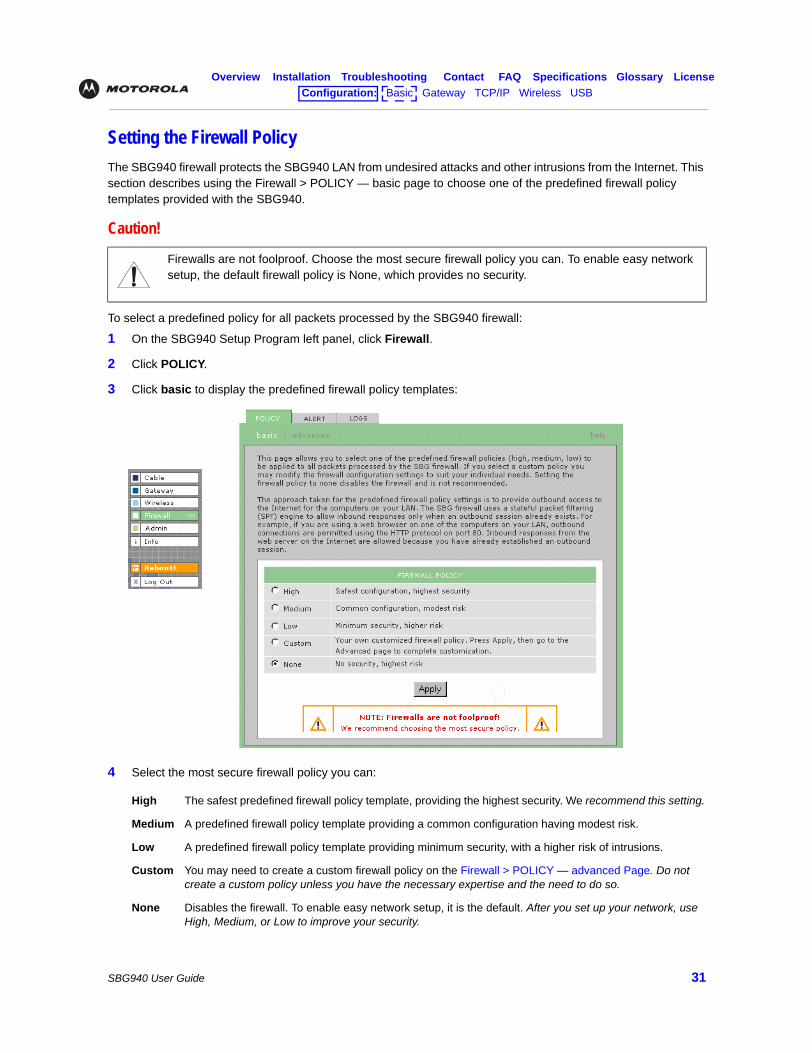
Setting the Firewall PolicyThe SBG940 firewall protects the SBG940 LAN from undesired attacks and other intrusions from the Internet. This section describes using the Firewall > POLICY — basic page to choose one of the predefined firewall policy templates provided with the SBG940.
To select a predefined policy for all packets processed by the SBG940 firewall:
1 On the SBG940 Setup Program left panel, click Firewall.
2 Click POLICY.
3 Click basic to display the predefined firewall policy templates:
4 Select the most secure firewall policy you can:
Caution!
Firewalls are not foolproof. Choose the most secure firewall policy you can. To enable easy network setup, the default firewall policy is None, which provides no security.
High The safest predefined firewall policy template, providing the highest security. We recommend this setting.
Medium A predefined firewall policy template providing a common configuration having modest risk.
Low A predefined firewall policy template providing minimum security, with a higher risk of intrusions.
Custom You may need to create a custom firewall policy on the Firewall > POLICY — advanced Page. Do not create a custom policy unless you have the necessary expertise and the need to do so.
None Disables the firewall. To enable easy network setup, it is the default. After you set up your network, use High, Medium, or Low to improve your security.
Overview Installation Troubleshooting Contact FAQ Specifications Glossary LicenseConfiguration: Basic Gateway TCP/IP Wireless USB
SBG940 User Guide 32
5 Click Apply to apply your changes.
If you have the need, you can:
• View the rules for the High, Medium, or Low predefined policy templates or create a custom policy on the Firewall > POLICY — advanced Page
• Configure a firewall alert on Firewall > ALERT — basic Page and Firewall > ALERT — email Page
• View the firewall logs on the Firewall > LOGS Page
For information about how the firewall can affect gaming, see “Gaming Configuration Guidelines”.
The predefined policies provide outbound Internet access for computers on the SBG940 LAN. The SBG940 firewall uses stateful inspection to allow inbound responses when there already is an outbound session running corresponding to the data flow. For example, if you use a web browser, outbound HTTP connections are permitted on port 80. Inbound responses from the Internet are allowed because an outbound session is established.
When required, you can configure the SBG940 firewall to allow inbound packets without first establishing an outbound session. You also need to configure a port forwarding entry on theGateway > PORT FORWARDING — config Page or a DMZ client on the Gateway > LAN — nat config Page.
After you edit some fields and click Apply, you are warned that you must reboot your SBG940 for your change to take effect. Rebooting takes 10 to 15 seconds. After rebooting, you must log in again.
Overview Installation Troubleshooting Contact FAQ Specifications Glossary LicenseConfiguration: Basic Gateway TCP/IP Wireless USB
SBG940 User Guide 33
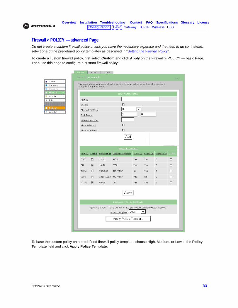
Firewall > POLICY — advanced PageDo not create a custom firewall policy unless you have the necessary expertise and the need to do so. Instead, select one of the predefined policy templates as described in “Setting the Firewall Policy”.
To create a custom firewall policy, first select Custom and click Apply on the Firewall > POLICY — basic Page. Then use this page to configure a custom firewall policy:
To base the custom policy on a predefined firewall policy template, choose High, Medium, or Low in the Policy Template field and click Apply Policy Template.
Overview Installation Troubleshooting Contact FAQ Specifications Glossary LicenseConfiguration: Basic Gateway TCP/IP Wireless USB
SBG940 User Guide 34
.
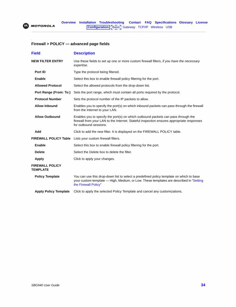
Firewall > POLICY — advanced page fields
Field Description
NEW FILTER ENTRY Use these fields to set up one or more custom firewall filters, if you have the necessary expertise.
Port ID Type the protocol being filtered.
Enable Select this box to enable firewall policy filtering for the port.
Allowed Protocol Select the allowed protocols from the drop-down list.
Port Range (From: To:) Sets the port range, which must contain all ports required by the protocol.
Protocol Number Sets the protocol number of the IP packets to allow.
Allow Inbound Enables you to specify the port(s) on which inbound packets can pass through the firewall from the Internet to your LAN.
Allow Outbound Enables you to specify the port(s) on which outbound packets can pass through the firewall from your LAN to the Internet. Stateful inspection ensures appropriate responses for outbound sessions.
Add Click to add the new filter. It is displayed on the FIREWALL POLICY table.
FIREWALL POLICY Table Lists your custom firewall filters.
Enable Select this box to enable firewall policy filtering for the port.
Delete Select the Delete box to delete the filter.
Apply Click to apply your changes.
FIREWALL POLICY TEMPLATE
Policy Template You can use this drop-down list to select a predefined policy template on which to base your custom template — High, Medium, or Low. These templates are described in “Setting the Firewall Policy”
Apply Policy Template Click to apply the selected Policy Template and cancel any customizations.
Overview Installation Troubleshooting Contact FAQ Specifications Glossary LicenseConfiguration: Basic Gateway TCP/IP Wireless USB
SBG940 User Guide 35
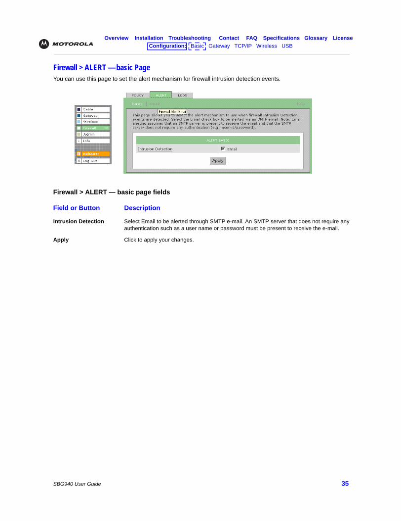
Firewall > ALERT — basic PageYou can use this page to set the alert mechanism for firewall intrusion detection events.
Firewall > ALERT — basic page fields
Field or Button Description
Intrusion Detection Select Email to be alerted through SMTP e-mail. An SMTP server that does not require any authentication such as a user name or password must be present to receive the e-mail.
Apply Click to apply your changes.
Overview Installation Troubleshooting Contact FAQ Specifications Glossary LicenseConfiguration: Basic Gateway TCP/IP Wireless USB
SBG940 User Guide 36
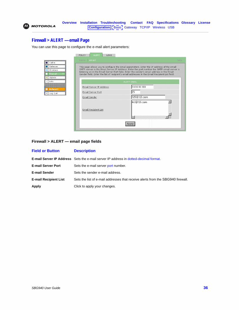
Firewall > ALERT — email PageYou can use this page to configure the e-mail alert parameters:
Firewall > ALERT — email page fields
Field or Button Description
E-mail Server IP Address Sets the e-mail server IP address in dotted-decimal format.
E-mail Server Port Sets the e-mail server port number.
E-mail Sender Sets the sender e-mail address.
E-mail Recipient List Sets the list of e-mail addresses that receive alerts from the SBG940 firewall.
Apply Click to apply your changes.
Overview Installation Troubleshooting Contact FAQ Specifications Glossary LicenseConfiguration: Basic Gateway TCP/IP Wireless USB
SBG940 User Guide 37
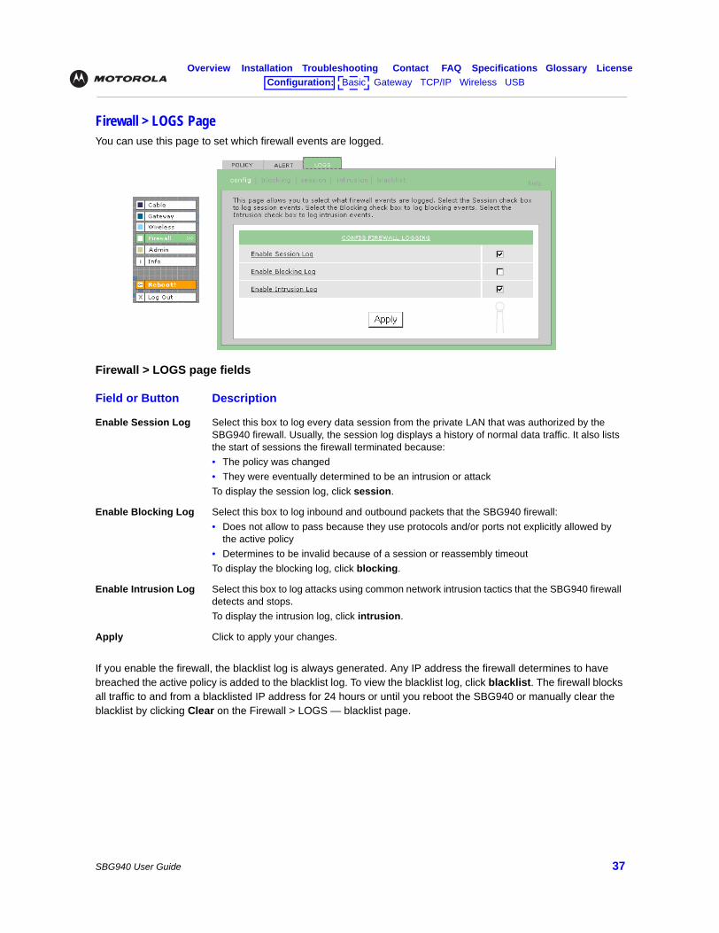
Firewall > LOGS PageYou can use this page to set which firewall events are logged.
If you enable the firewall, the blacklist log is always generated. Any IP address the firewall determines to have breached the active policy is added to the blacklist log. To view the blacklist log, click blacklist. The firewall blocks all traffic to and from a blacklisted IP address for 24 hours or until you reboot the SBG940 or manually clear the blacklist by clicking Clear on the Firewall > LOGS — blacklist page.
Firewall > LOGS page fields
Field or Button Description
Enable Session Log Select this box to log every data session from the private LAN that was authorized by the SBG940 firewall. Usually, the session log displays a history of normal data traffic. It also lists the start of sessions the firewall terminated because:• The policy was changed• They were eventually determined to be an intrusion or attackTo display the session log, click session.
Enable Blocking Log Select this box to log inbound and outbound packets that the SBG940 firewall:• Does not allow to pass because they use protocols and/or ports not explicitly allowed by
the active policy• Determines to be invalid because of a session or reassembly timeoutTo display the blocking log, click blocking.
Enable Intrusion Log Select this box to log attacks using common network intrusion tactics that the SBG940 firewall detects and stops.To display the intrusion log, click intrusion.
Apply Click to apply your changes.
Overview Installation Troubleshooting Contact FAQ Specifications Glossary LicenseConfiguration: Basic Gateway TCP/IP Wireless USB
SBG940 User Guide 38
Gaming Configuration GuidelinesThe following subsections provide information about configuring the SBG940 firewall and DMZ for gaming.
Configuring the Firewall for GamingBy default, the SBG940 firewall is disabled. If, as recommended, you enable the firewall, refer to the game’s documentation to ensure that the necessary ports are open for use by that game.
The pre-defined SBG940 firewall policies affect Xbox LiveTM as follows:
Configuring Port TriggersBecause the SBG940 has pre-defined port triggers for games using any of the following applications, no user action is required to enable them:
• DirectX 7 and DirectX 8
• MSN Games by Zone.com
• Battle.net®
For a list of games supported by Battle.net, visit http://www.battle.net.
You may need to create custom port triggers to enable other games to operate properly. If you set custom port triggers and enable the firewall, you must customize the firewall to allow traffic through those ports. To create custom port triggers, use the Gateway > PORT TRIGGERS — custom Page.
Low Xbox Live data can pass through the firewall. No user action is required.
Medium or high To enable Xbox Live traffic to pass, you must configure:• Choose Custom on the Firewall > POLICY — basic Page• UDP 88:88 and UDP/TCP 3074:3074 on the Firewall > POLICY — advanced Page
Overview Installation Troubleshooting Contact FAQ Specifications Glossary LicenseConfiguration: Basic Gateway TCP/IP Wireless USB
SBG940 User Guide 39
Configuring a Gaming DMZ Host
Some games and game devices require one of:
• The use of random ports
• The forwarding of unsolicited traffic
For example, to connect a PlayStation® 2 for PS2® online gaming, designate it as the gaming DMZ host because the ports required vary from game to game. For these games, we recommend configuring the gaming computer or device as a gaming DMZ device.
To configure a gaming DMZ device, on the Gateway > LAN — dhcp leases Page:
1 Reserve a private IP address for the computer or game device MAC address.
2 Designate the device as a DMZ device.
You can reserve IP addresses for multiple devices, but only one can be designated as the gaming DMZ at once.
Caution!
The gaming DMZ host is not protected by the firewall. It is open to communication or hacking from any computer on the Internet. Consider carefully before configuring a device to be in the DMZ.
Overview Installation Troubleshooting Contact FAQ Specifications Glossary LicenseConfiguration: Basic Gateway TCP/IP Wireless USB
SBG940 User Guide 40
Configuring the GatewayThis section describes the Gateway configuration pages in the SBG940 Setup Program:
• Gateway > STATUS Page
• Gateway > WAN Page
• Gateway > LAN — nat config Page
• Gateway > LAN — dhcp server config Page
• Gateway > LAN — dhcp leases Page
• Gateway > PORT FORWARDING — status Page
• Gateway > PORT FORWARDING — config Page
• Gateway > PORT TRIGGERS — predefined Page
• Gateway > PORT TRIGGERS — custom Page
• Gateway > LOG Page
After you edit some fields and click Apply, you are warned that you must reboot your SBG940 for your change to take effect. Rebooting takes 10 to 15 seconds. After rebooting, you must log in again.
Overview Installation Troubleshooting Contact FAQ Specifications Glossary LicenseConfiguration: Basic Gateway TCP/IP Wireless USB
SBG940 User Guide 41
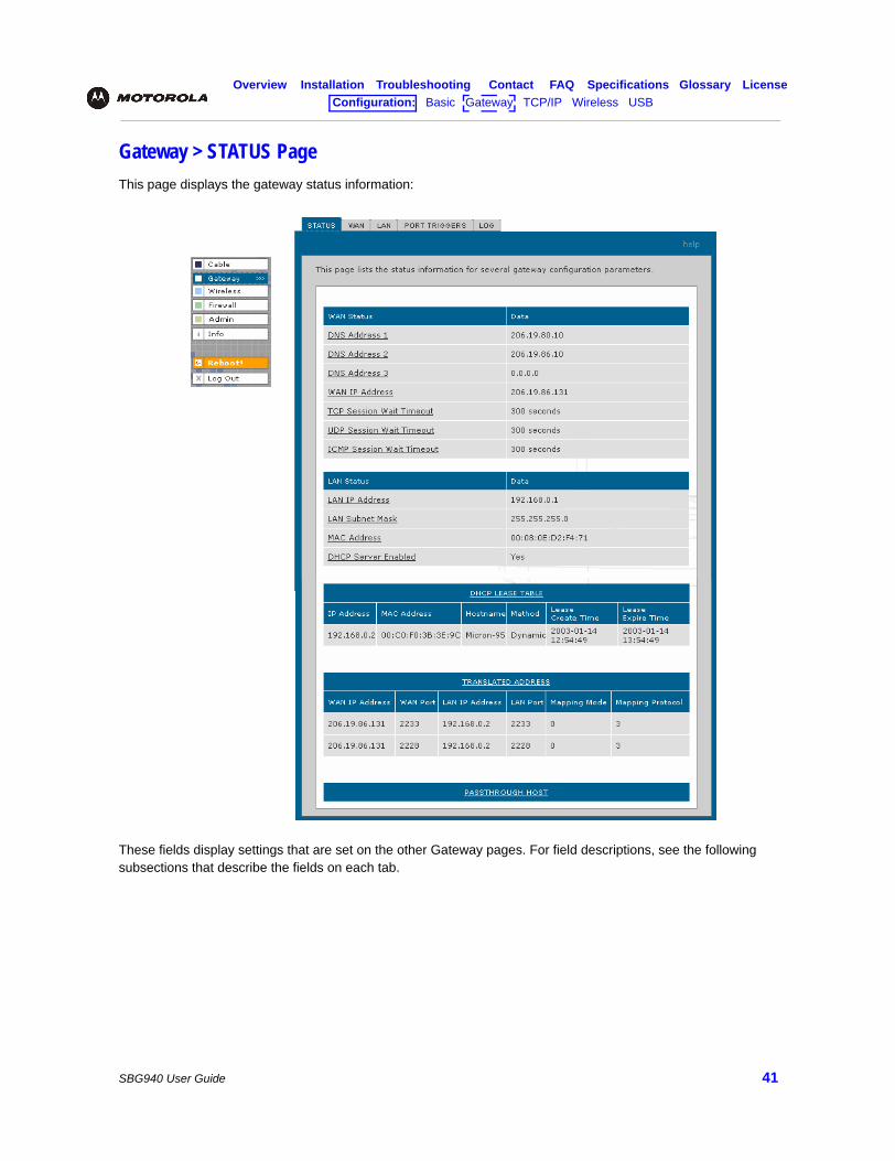
Gateway > STATUS PageThis page displays the gateway status information:
These fields display settings that are set on the other Gateway pages. For field descriptions, see the following subsections that describe the fields on each tab.
Overview Installation Troubleshooting Contact FAQ Specifications Glossary LicenseConfiguration: Basic Gateway TCP/IP Wireless USB
SBG940 User Guide 42
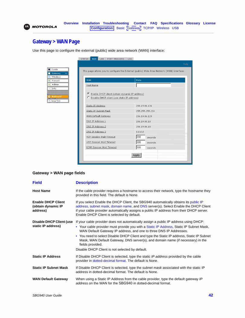
Gateway > WAN PageUse this page to configure the external (public) wide area network (WAN) interface:
Gateway > WAN page fields
Field Description
Host Name If the cable provider requires a hostname to access their network, type the hostname they provided in this field. The default is None.
Enable DHCP Client (obtain dynamic IP address)
If you select Enable the DHCP Client, the SBG940 automatically obtains its public IP address, subnet mask, domain name, and DNS server(s). Select Enable the DHCP Client if your cable provider automatically assigns a public IP address from their DHCP server. Enable DHCP Client is selected by default.
Disable DHCP Client (use static IP address)
If your cable provider does not automatically assign a public IP address using DHCP:• Your cable provider must provide you with a Static IP Address, Static IP Subnet Mask,
WAN Default Gateway IP address, and one to three DNS IP Addresses. • You need to select Disable DHCP Client and type the Static IP address, Static IP Subnet
Mask, WAN Default Gateway, DNS server(s), and domain name (if necessary) in the fields provided.
Disable DHCP Client is not selected by default.
Static IP Address If Disable DHCP Client is selected, type the static IP address provided by the cable provider in dotted-decimal format. The default is None.
Static IP Subnet Mask If Disable DHCP Client is selected, type the subnet mask associated with the static IP address in dotted-decimal format. The default is None.
WAN Default Gateway When using a Static IP Address from the cable provider, type the default gateway IP address on the WAN for the SBG940 in dotted-decimal format.
Overview Installation Troubleshooting Contact FAQ Specifications Glossary LicenseConfiguration: Basic Gateway TCP/IP Wireless USB
SBG940 User Guide 43
DNS IP Address 1 DNS IP Address 2 DNS IP Address 3
The cable provider DNS server provides name-to-IP address resolution. If the cable provider does not automatically assign DNS addresses from their DHCP server, they must provide at least one DNS server IP address to enter in these fields in dotted-decimal format. The default is None.
TCP Session Wait Timeout
Sets the maximum time in seconds to wait before assuming a TCP session has timed out. The default is 24 hours.
UDP Session Wait Timeout
Sets the maximum time in seconds to wait before assuming a UDP session has timed out. The default is 300 seconds (5 minutes).
ICMP Session Wait Timeout
Sets the maximum time in seconds to wait before assuming an ICMP session has timed out. The default is 300 seconds (5 minutes).
Apply Click to apply your changes.
Gateway > WAN page fields (continued)
Field Description
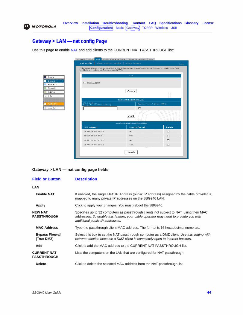
Overview Installation Troubleshooting Contact FAQ Specifications Glossary LicenseConfiguration: Basic Gateway TCP/IP Wireless USB
SBG940 User Guide 44
Gateway > LAN — nat config PageUse this page to enable NAT and add clients to the CURRENT NAT PASSTHROUGH list:
Gateway > LAN — nat config page fields
Field or Button Description
LAN
Enable NAT If enabled, the single HFC IP Address (public IP address) assigned by the cable provider is mapped to many private IP addresses on the SBG940 LAN.
Apply Click to apply your changes. You must reboot the SBG940.
NEW NAT PASSTHROUGH
Specifies up to 32 computers as passthrough clients not subject to NAT, using their MAC addresses. To enable this feature, your cable operator may need to provide you with additional public IP addresses.
MAC Address Type the passthrough client MAC address. The format is 16 hexadecimal numerals.
Bypass Firewall(True DMZ)
Select this box to set the NAT passthrough computer as a DMZ client. Use this setting with extreme caution because a DMZ client is completely open to Internet hackers.
Add Click to add the MAC address to the CURRENT NAT PASSTHROUGH list.
CURRENT NAT PASSTHROUGH
Lists the computers on the LAN that are configured for NAT passthrough.
Delete Click to delete the selected MAC address from the NAT passthrough list.
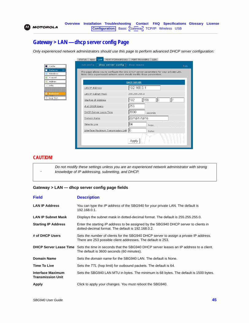
Overview Installation Troubleshooting Contact FAQ Specifications Glossary LicenseConfiguration: Basic Gateway TCP/IP Wireless USB
SBG940 User Guide 45
Gateway > LAN — dhcp server config PageOnly experienced network administrators should use this page to perform advanced DHCP server configuration:
CAUTION!
Do not modify these settings unless you are an experienced network administrator with strong knowledge of IP addressing, subnetting, and DHCP.
Gateway > LAN — dhcp server config page fields
Field Description
LAN IP Address You can type the IP address of the SBG940 for your private LAN. The default is 192.168.0.1.
LAN IP Subnet Mask Displays the subnet mask in dotted-decimal format. The default is 255.255.255.0.
Starting IP Address Enter the starting IP address to be assigned by the SBG940 DHCP server to clients in dotted-decimal format. The default is 192.168.0.2.
# of DHCP Users Sets the number of clients for the SBG940 DHCP server to assign a private IP address. There are 253 possible client addresses. The default is 253.
DHCP Server Lease Time Sets the time in seconds that the SBG940 DHCP server leases an IP address to a client. The default is 3600 seconds (60 minutes).
Domain Name Sets the domain name for the SBG940 LAN. The default is None.
Time To Live Sets the TTL (hop limit) for outbound packets. The default is 64.
Interface Maximum Transmission Unit
Sets the SBG940 LAN MTU in bytes. The minimum is 68 bytes. The default is 1500 bytes.
Apply Click to apply your changes. You must reboot the SBG940.
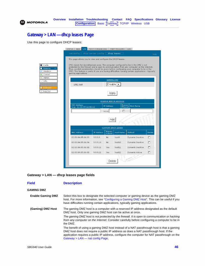
Overview Installation Troubleshooting Contact FAQ Specifications Glossary LicenseConfiguration: Basic Gateway TCP/IP Wireless USB
SBG940 User Guide 46
Gateway > LAN — dhcp leases PageUse this page to configure DHCP leases:
Gateway > LAN — dhcp leases page fields
Field Description
GAMING DMZ
Enable Gaming DMZ Select this box to designate the selected computer or gaming device as the gaming DMZ host. For more information, see “Configuring a Gaming DMZ Host”. This can be useful if you have difficulties running certain applications, typically gaming applications.
(Gaming) DMZ Host The gaming DMZ host is a computer with a reserved IP address designated as the default DMZ host. Only one gaming DMZ host can be active at once.The gaming DMZ host is not protected by the firewall. It is open to communication or hacking from any computer on the Internet. Consider carefully before configuring a computer to be in the DMZ. The benefit of using a gaming DMZ host instead of a NAT passthrough host is that a gaming DMZ host does not require a public IP address as does a NAT passthrough host. If the application requires a public IP address, configure the computer for NAT passthrough on the Gateway > LAN — nat config Page.
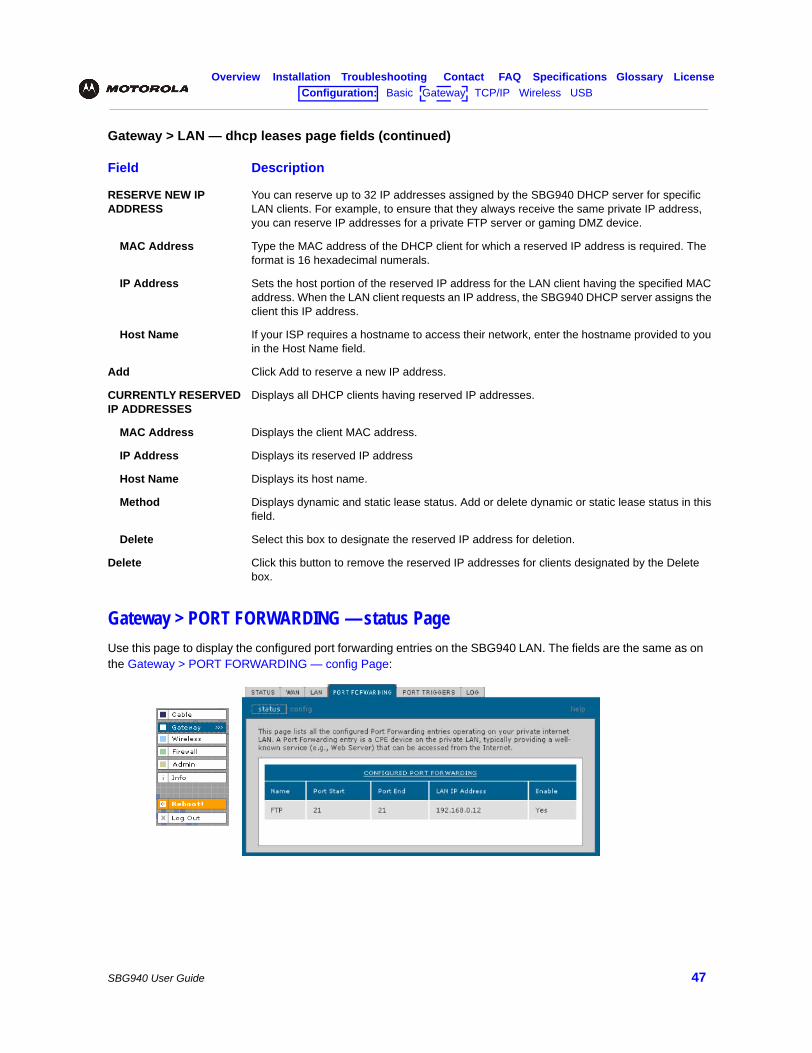
Overview Installation Troubleshooting Contact FAQ Specifications Glossary LicenseConfiguration: Basic Gateway TCP/IP Wireless USB
SBG940 User Guide 47
Gateway > PORT FORWARDING — status PageUse this page to display the configured port forwarding entries on the SBG940 LAN. The fields are the same as on the Gateway > PORT FORWARDING — config Page:
RESERVE NEW IP ADDRESS
You can reserve up to 32 IP addresses assigned by the SBG940 DHCP server for specific LAN clients. For example, to ensure that they always receive the same private IP address, you can reserve IP addresses for a private FTP server or gaming DMZ device.
MAC Address Type the MAC address of the DHCP client for which a reserved IP address is required. The format is 16 hexadecimal numerals.
IP Address Sets the host portion of the reserved IP address for the LAN client having the specified MAC address. When the LAN client requests an IP address, the SBG940 DHCP server assigns the client this IP address.
Host Name If your ISP requires a hostname to access their network, enter the hostname provided to you in the Host Name field.
Add Click Add to reserve a new IP address.
CURRENTLY RESERVED IP ADDRESSES
Displays all DHCP clients having reserved IP addresses.
MAC Address Displays the client MAC address.
IP Address Displays its reserved IP address
Host Name Displays its host name.
Method Displays dynamic and static lease status. Add or delete dynamic or static lease status in this field.
Delete Select this box to designate the reserved IP address for deletion.
Delete Click this button to remove the reserved IP addresses for clients designated by the Delete box.
Gateway > LAN — dhcp leases page fields (continued)
Field Description
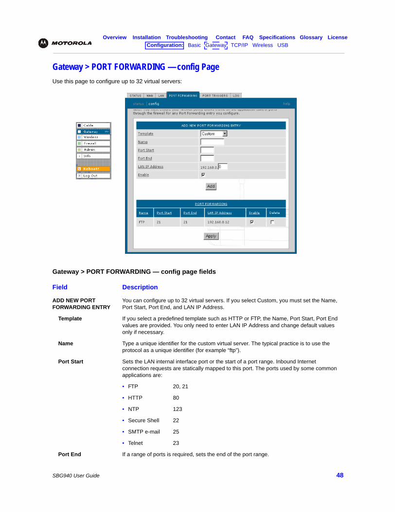
Overview Installation Troubleshooting Contact FAQ Specifications Glossary LicenseConfiguration: Basic Gateway TCP/IP Wireless USB
SBG940 User Guide 48
Gateway > PORT FORWARDING — config PageUse this page to configure up to 32 virtual servers:
Gateway > PORT FORWARDING — config page fields
Field Description
ADD NEW PORT FORWARDING ENTRY
You can configure up to 32 virtual servers. If you select Custom, you must set the Name, Port Start, Port End, and LAN IP Address.
Template If you select a predefined template such as HTTP or FTP, the Name, Port Start, Port End values are provided. You only need to enter LAN IP Address and change default values only if necessary.
Name Type a unique identifier for the custom virtual server. The typical practice is to use the protocol as a unique identifier (for example “ftp”).
Port Start Sets the LAN internal interface port or the start of a port range. Inbound Internet connection requests are statically mapped to this port. The ports used by some common applications are:
• FTP 20, 21
• HTTP 80
• NTP 123
• Secure Shell 22
• SMTP e-mail 25
• Telnet 23
Port End If a range of ports is required, sets the end of the port range.
Overview Installation Troubleshooting Contact FAQ Specifications Glossary LicenseConfiguration: Basic Gateway TCP/IP Wireless USB
SBG940 User Guide 49
Gateway > PORT TRIGGERS — predefined PageWhen you run a PC application that accesses the Internet, it communicates with a computer on the Internet. In some applications, especially gaming, the computer on the Internet also communicates with your PC. Because NAT does not normally allow these incoming connections, the SBG940 supports port triggering.
The SBG940 is preconfigured with port triggering for common applications. You can also configure additional port triggers if needed. Configuring port triggers for an application requires:
• The application transport protocol — TCP or UDP
• The application port number
You can use the default values for the remaining parameters.
LAN IP Address Sets the private LAN IP address for the port forwarding page. An Internet user must know the public IP address to access any port forwarding entry you define on the private LAN.
Enable Select this box to enable the port forwarding entries to be accessed through NAT.
Add Click to add the virtual server to the PORT FORWARDING list.
PORT FORWARDING Displays the configured custom virtual servers.
Gateway > PORT FORWARDING — config page fields (continued)
Field Description
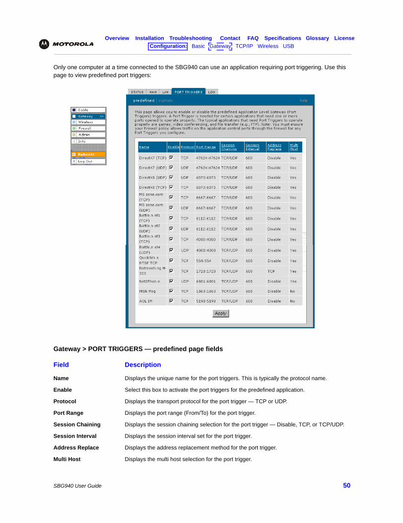
Overview Installation Troubleshooting Contact FAQ Specifications Glossary LicenseConfiguration: Basic Gateway TCP/IP Wireless USB
SBG940 User Guide 50
Only one computer at a time connected to the SBG940 can use an application requiring port triggering. Use this page to view predefined port triggers:
Gateway > PORT TRIGGERS — predefined page fields
Field Description
Name Displays the unique name for the port triggers. This is typically the protocol name.
Enable Select this box to activate the port triggers for the predefined application.
Protocol Displays the transport protocol for the port trigger — TCP or UDP.
Port Range Displays the port range (From/To) for the port trigger.
Session Chaining Displays the session chaining selection for the port trigger — Disable, TCP, or TCP/UDP.
Session Interval Displays the session interval set for the port trigger.
Address Replace Displays the address replacement method for the port trigger.
Multi Host Displays the multi host selection for the port trigger.
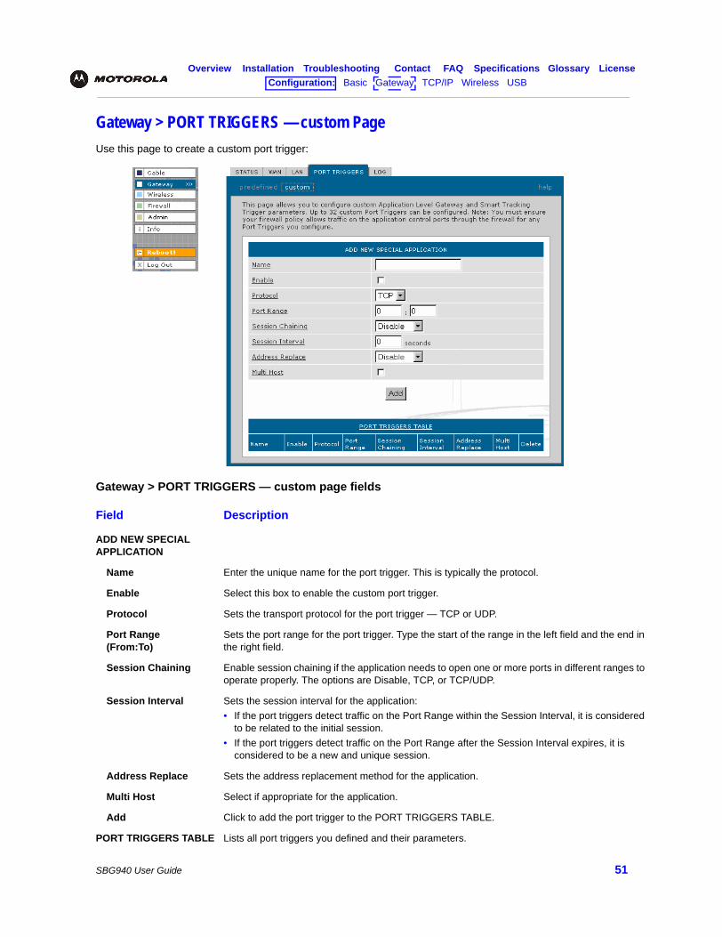
Overview Installation Troubleshooting Contact FAQ Specifications Glossary LicenseConfiguration: Basic Gateway TCP/IP Wireless USB
SBG940 User Guide 51
Gateway > PORT TRIGGERS — custom PageUse this page to create a custom port trigger:
Gateway > PORT TRIGGERS — custom page fields
Field Description
ADD NEW SPECIAL APPLICATION
Name Enter the unique name for the port trigger. This is typically the protocol.
Enable Select this box to enable the custom port trigger.
Protocol Sets the transport protocol for the port trigger — TCP or UDP.
Port Range (From:To)
Sets the port range for the port trigger. Type the start of the range in the left field and the end in the right field.
Session Chaining Enable session chaining if the application needs to open one or more ports in different ranges to operate properly. The options are Disable, TCP, or TCP/UDP.
Session Interval Sets the session interval for the application:• If the port triggers detect traffic on the Port Range within the Session Interval, it is considered
to be related to the initial session. • If the port triggers detect traffic on the Port Range after the Session Interval expires, it is
considered to be a new and unique session.
Address Replace Sets the address replacement method for the application.
Multi Host Select if appropriate for the application.
Add Click to add the port trigger to the PORT TRIGGERS TABLE.
PORT TRIGGERS TABLE Lists all port triggers you defined and their parameters.
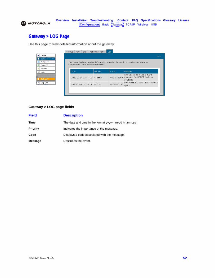
Overview Installation Troubleshooting Contact FAQ Specifications Glossary LicenseConfiguration: Basic Gateway TCP/IP Wireless USB
SBG940 User Guide 52
Gateway > LOG PageUse this page to view detailed information about the gateway:
Gateway > LOG page fields
Field Description
Time The date and time in the format yyyy-mm-dd hh:mm:ss
Priority Indicates the importance of the message.
Code Displays a code associated with the message.
Message Describes the event.
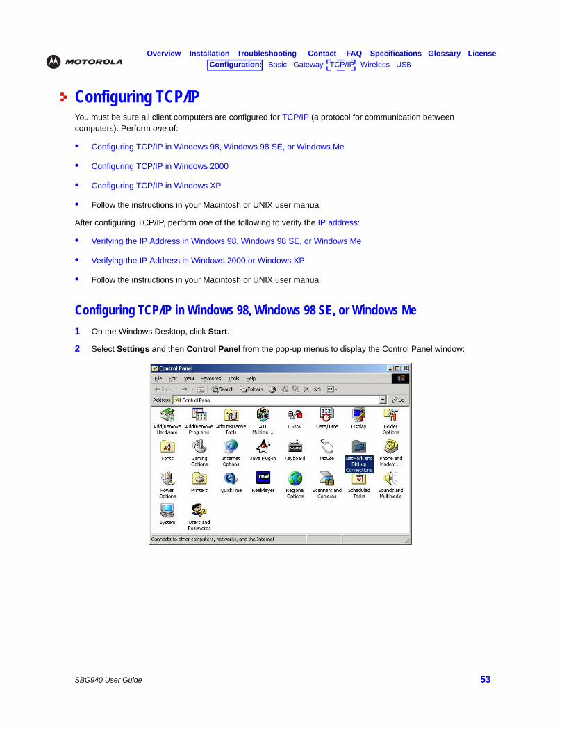
Overview Installation Troubleshooting Contact FAQ Specifications Glossary LicenseConfiguration: Basic Gateway TCP/IP Wireless USB
SBG940 User Guide 53
Configuring TCP/IPYou must be sure all client computers are configured for TCP/IP (a protocol for communication between computers). Perform one of:
• Configuring TCP/IP in Windows 98, Windows 98 SE, or Windows Me
• Configuring TCP/IP in Windows 2000
• Configuring TCP/IP in Windows XP
• Follow the instructions in your Macintosh or UNIX user manual
After configuring TCP/IP, perform one of the following to verify the IP address:
• Verifying the IP Address in Windows 98, Windows 98 SE, or Windows Me
• Verifying the IP Address in Windows 2000 or Windows XP
• Follow the instructions in your Macintosh or UNIX user manual
Configuring TCP/IP in Windows 98, Windows 98 SE, or Windows Me1 On the Windows Desktop, click Start.
2 Select Settings and then Control Panel from the pop-up menus to display the Control Panel window:
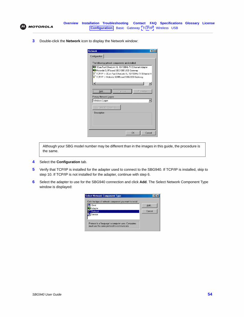
Overview Installation Troubleshooting Contact FAQ Specifications Glossary LicenseConfiguration: Basic Gateway TCP/IP Wireless USB
SBG940 User Guide 54
3 Double-click the Network icon to display the Network window:
4 Select the Configuration tab.
5 Verify that TCP/IP is installed for the adapter used to connect to the SBG940. If TCP/IP is installed, skip to step 10. If TCP/IP is not installed for the adapter, continue with step 6.
6 Select the adapter to use for the SBG940 connection and click Add. The Select Network Component Type window is displayed:
Although your SBG model number may be different than in the images in this guide, the procedure is the same.
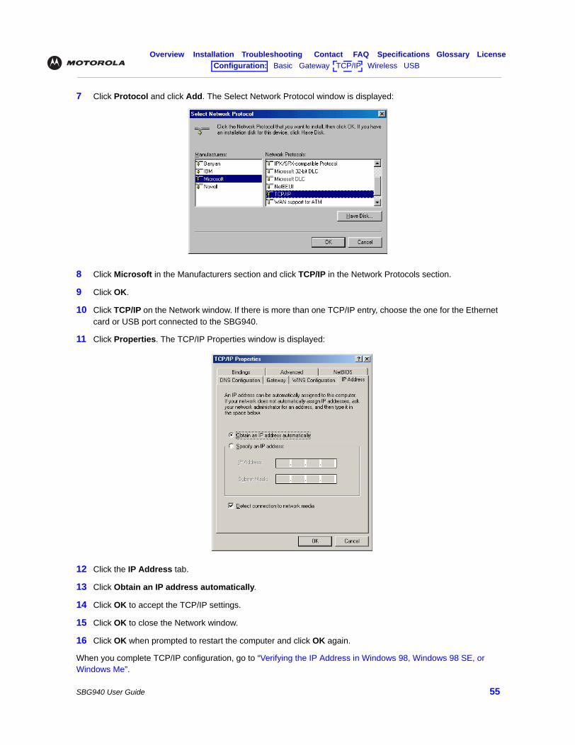
Overview Installation Troubleshooting Contact FAQ Specifications Glossary LicenseConfiguration: Basic Gateway TCP/IP Wireless USB
SBG940 User Guide 55
7 Click Protocol and click Add. The Select Network Protocol window is displayed:
8 Click Microsoft in the Manufacturers section and click TCP/IP in the Network Protocols section.
9 Click OK.
10 Click TCP/IP on the Network window. If there is more than one TCP/IP entry, choose the one for the Ethernet card or USB port connected to the SBG940.
11 Click Properties. The TCP/IP Properties window is displayed:
12 Click the IP Address tab.
13 Click Obtain an IP address automatically.
14 Click OK to accept the TCP/IP settings.
15 Click OK to close the Network window.
16 Click OK when prompted to restart the computer and click OK again.
When you complete TCP/IP configuration, go to “Verifying the IP Address in Windows 98, Windows 98 SE, or Windows Me”.
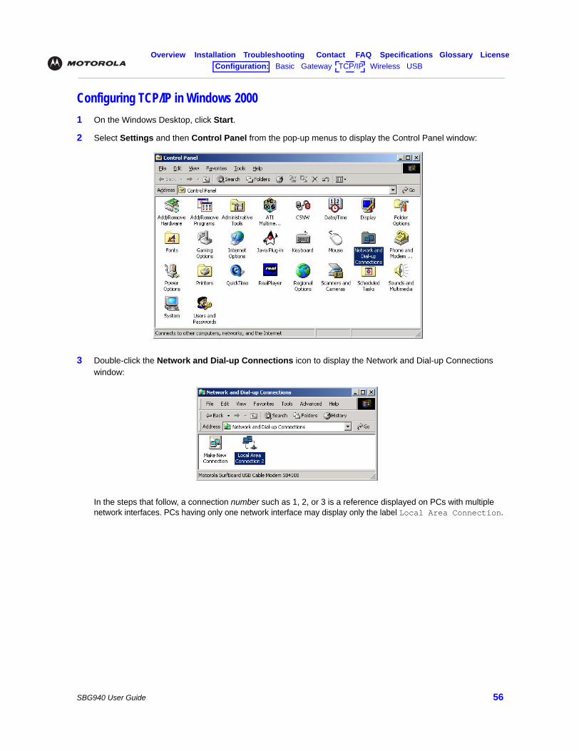
Overview Installation Troubleshooting Contact FAQ Specifications Glossary LicenseConfiguration: Basic Gateway TCP/IP Wireless USB
SBG940 User Guide 56
Configuring TCP/IP in Windows 20001 On the Windows Desktop, click Start.
2 Select Settings and then Control Panel from the pop-up menus to display the Control Panel window:
3 Double-click the Network and Dial-up Connections icon to display the Network and Dial-up Connections window:
In the steps that follow, a connection number such as 1, 2, or 3 is a reference displayed on PCs with multiple network interfaces. PCs having only one network interface may display only the label Local Area Connection.
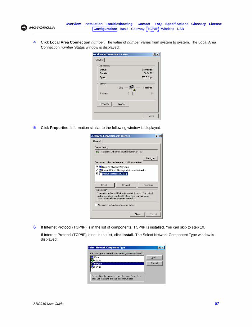
Overview Installation Troubleshooting Contact FAQ Specifications Glossary LicenseConfiguration: Basic Gateway TCP/IP Wireless USB
SBG940 User Guide 57
4 Click Local Area Connection number. The value of number varies from system to system. The Local Area Connection number Status window is displayed:
5 Click Properties. Information similar to the following window is displayed:
6 If Internet Protocol (TCP/IP) is in the list of components, TCP/IP is installed. You can skip to step 10.
If Internet Protocol (TCP/IP) is not in the list, click Install. The Select Network Component Type window is displayed:
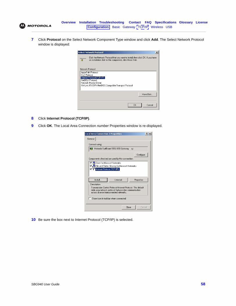
Overview Installation Troubleshooting Contact FAQ Specifications Glossary LicenseConfiguration: Basic Gateway TCP/IP Wireless USB
SBG940 User Guide 58
7 Click Protocol on the Select Network Component Type window and click Add. The Select Network Protocol window is displayed:
8 Click Internet Protocol (TCP/IP).
9 Click OK. The Local Area Connection number Properties window is re-displayed.
10 Be sure the box next to Internet Protocol (TCP/IP) is selected.
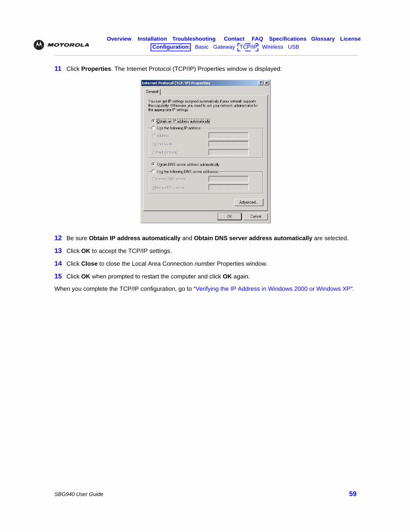
Overview Installation Troubleshooting Contact FAQ Specifications Glossary LicenseConfiguration: Basic Gateway TCP/IP Wireless USB
SBG940 User Guide 59
11 Click Properties. The Internet Protocol (TCP/IP) Properties window is displayed:
12 Be sure Obtain IP address automatically and Obtain DNS server address automatically are selected.
13 Click OK to accept the TCP/IP settings.
14 Click Close to close the Local Area Connection number Properties window.
15 Click OK when prompted to restart the computer and click OK again.
When you complete the TCP/IP configuration, go to “Verifying the IP Address in Windows 2000 or Windows XP”.
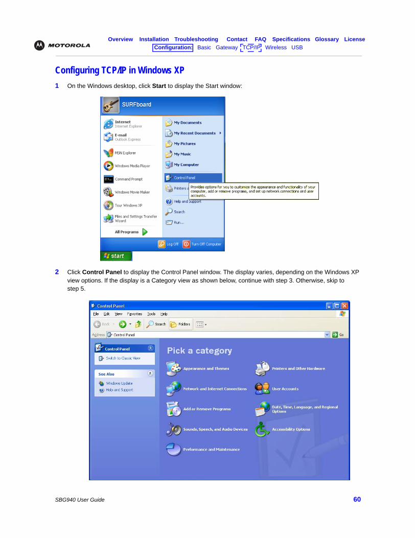
Overview Installation Troubleshooting Contact FAQ Specifications Glossary LicenseConfiguration: Basic Gateway TCP/IP Wireless USB
SBG940 User Guide 60
Configuring TCP/IP in Windows XP1 On the Windows desktop, click Start to display the Start window:
2 Click Control Panel to display the Control Panel window. The display varies, depending on the Windows XP view options. If the display is a Category view as shown below, continue with step 3. Otherwise, skip to step 5.
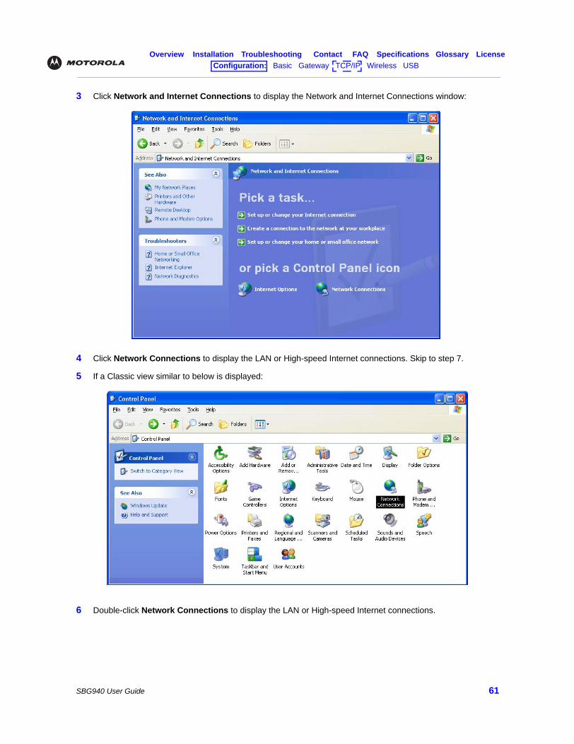
Overview Installation Troubleshooting Contact FAQ Specifications Glossary LicenseConfiguration: Basic Gateway TCP/IP Wireless USB
SBG940 User Guide 61
3 Click Network and Internet Connections to display the Network and Internet Connections window:
4 Click Network Connections to display the LAN or High-speed Internet connections. Skip to step 7.
5 If a Classic view similar to below is displayed:
6 Double-click Network Connections to display the LAN or High-speed Internet connections.
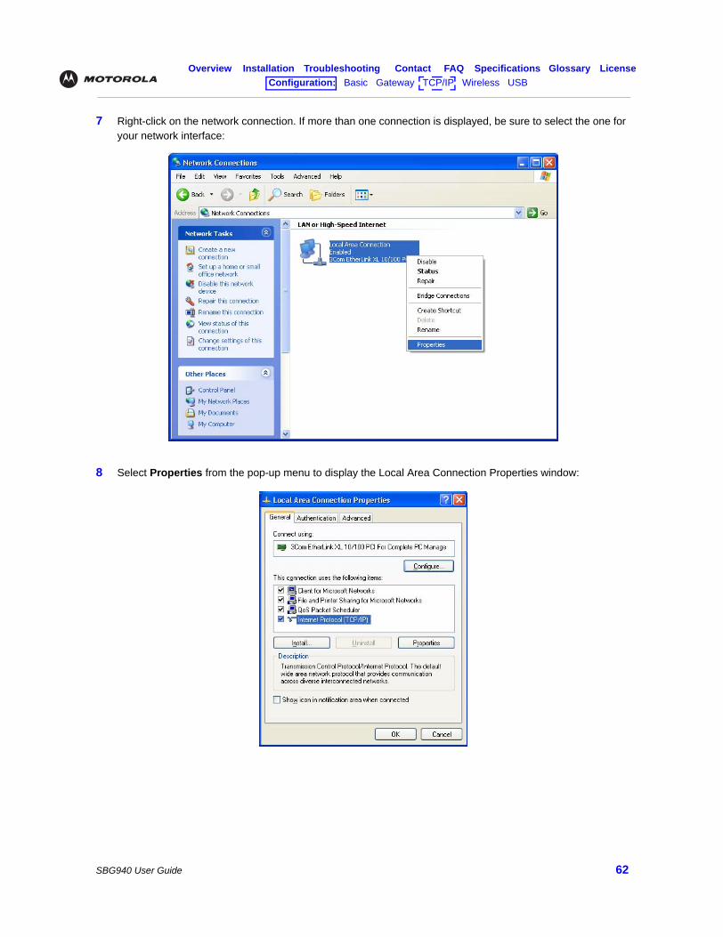
Overview Installation Troubleshooting Contact FAQ Specifications Glossary LicenseConfiguration: Basic Gateway TCP/IP Wireless USB
SBG940 User Guide 62
7 Right-click on the network connection. If more than one connection is displayed, be sure to select the one for your network interface:
8 Select Properties from the pop-up menu to display the Local Area Connection Properties window:
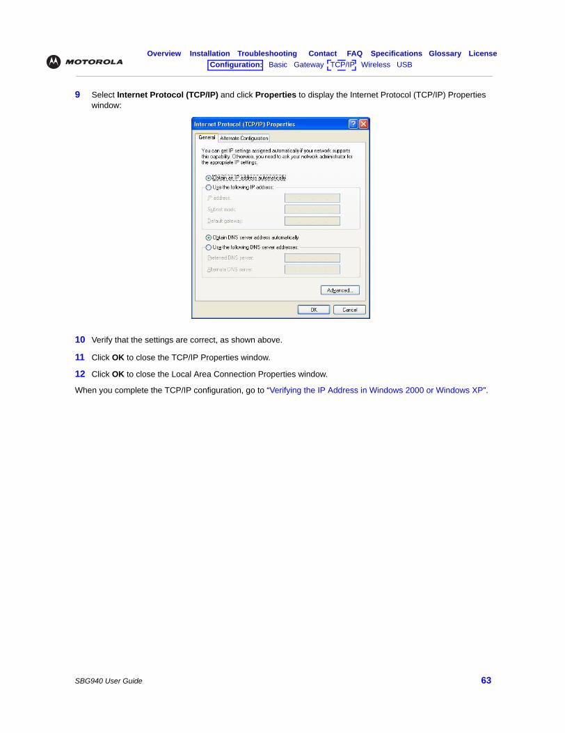
Overview Installation Troubleshooting Contact FAQ Specifications Glossary LicenseConfiguration: Basic Gateway TCP/IP Wireless USB
SBG940 User Guide 63
9 Select Internet Protocol (TCP/IP) and click Properties to display the Internet Protocol (TCP/IP) Properties window:
10 Verify that the settings are correct, as shown above.
11 Click OK to close the TCP/IP Properties window.
12 Click OK to close the Local Area Connection Properties window.
When you complete the TCP/IP configuration, go to “Verifying the IP Address in Windows 2000 or Windows XP”.
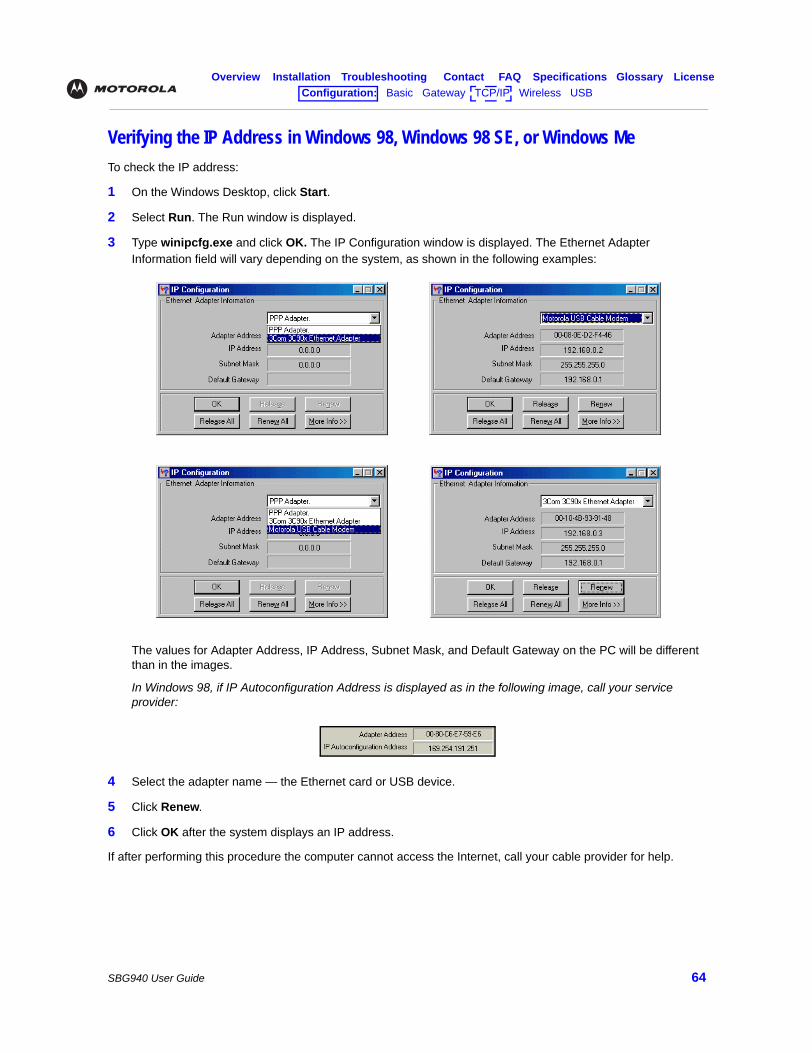
Overview Installation Troubleshooting Contact FAQ Specifications Glossary LicenseConfiguration: Basic Gateway TCP/IP Wireless USB
SBG940 User Guide 64
Verifying the IP Address in Windows 98, Windows 98 SE, or Windows Me To check the IP address:
1 On the Windows Desktop, click Start.
2 Select Run. The Run window is displayed.
3 Type winipcfg.exe and click OK. The IP Configuration window is displayed. The Ethernet Adapter Information field will vary depending on the system, as shown in the following examples:
The values for Adapter Address, IP Address, Subnet Mask, and Default Gateway on the PC will be different than in the images.
In Windows 98, if IP Autoconfiguration Address is displayed as in the following image, call your service provider:
4 Select the adapter name — the Ethernet card or USB device.
5 Click Renew.
6 Click OK after the system displays an IP address.
If after performing this procedure the computer cannot access the Internet, call your cable provider for help.
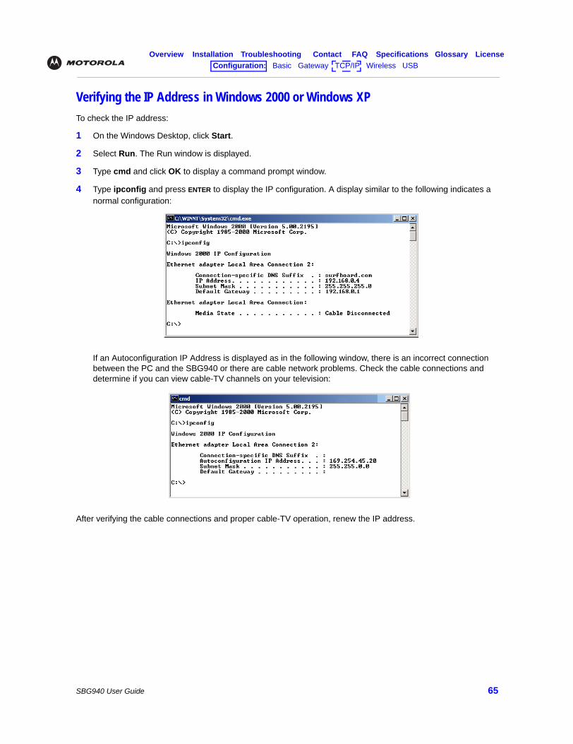
Overview Installation Troubleshooting Contact FAQ Specifications Glossary LicenseConfiguration: Basic Gateway TCP/IP Wireless USB
SBG940 User Guide 65
Verifying the IP Address in Windows 2000 or Windows XP To check the IP address:
1 On the Windows Desktop, click Start.
2 Select Run. The Run window is displayed.
3 Type cmd and click OK to display a command prompt window.
4 Type ipconfig and press ENTER to display the IP configuration. A display similar to the following indicates a normal configuration:
If an Autoconfiguration IP Address is displayed as in the following window, there is an incorrect connection between the PC and the SBG940 or there are cable network problems. Check the cable connections and determine if you can view cable-TV channels on your television:
After verifying the cable connections and proper cable-TV operation, renew the IP address.
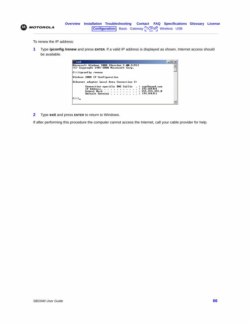
Overview Installation Troubleshooting Contact FAQ Specifications Glossary LicenseConfiguration: Basic Gateway TCP/IP Wireless USB
SBG940 User Guide 66
To renew the IP address:
1 Type ipconfig /renew and press ENTER. If a valid IP address is displayed as shown, Internet access should be available.
2 Type exit and press ENTER to return to Windows.
If after performing this procedure the computer cannot access the Internet, call your cable provider for help.
Overview Installation Troubleshooting Contact FAQ Specifications Glossary LicenseConfiguration: Basic Gateway TCP/IP Wireless USB
SBG940 User Guide 67
Setting Up Your Wireless LANYou can use the SBG940 as an access point for a wireless LAN (WLAN) without changing its default settings.
To enable security for your WLAN, you can do the following on the SBG940:
Connect at least one computer to the SBG940 Ethernet or USB port to perform configuration. Do not attempt to configure the SBG940 over a wireless connection.
You need to configure each wireless client (station) to access the SBG940 LAN as described in “Configuring the Wireless Clients”.
For descriptions of all wireless configuration fields, see “Configuring a Wireless Client with the Network Name (ESSID)”.
Another step to improve wireless security is to place wireless components away from windows. This decreases the signal strength outside the intended area.
Caution!
To prevent unauthorized eavesdropping or access to WLAN data, you must enable wireless security. The default SBG940 settings provide no wireless security. After your WLAN is operational, be sure to enable wireless security.
To Perform Use in Setup Program
Encrypt wireless transmissions and restrict WLAN access
Encrypting Wireless LAN Transmissions Wireless > SECURITY — basic Page
Further prevent unauthorized WLAN intrusions
Restricting Wireless LAN Access Wireless > SECURITY — advanced Page
Caution!
Never provide your ESSID, WPA or WEP passphrase, or WEP key to anyone who is not authorized to use your WLAN.
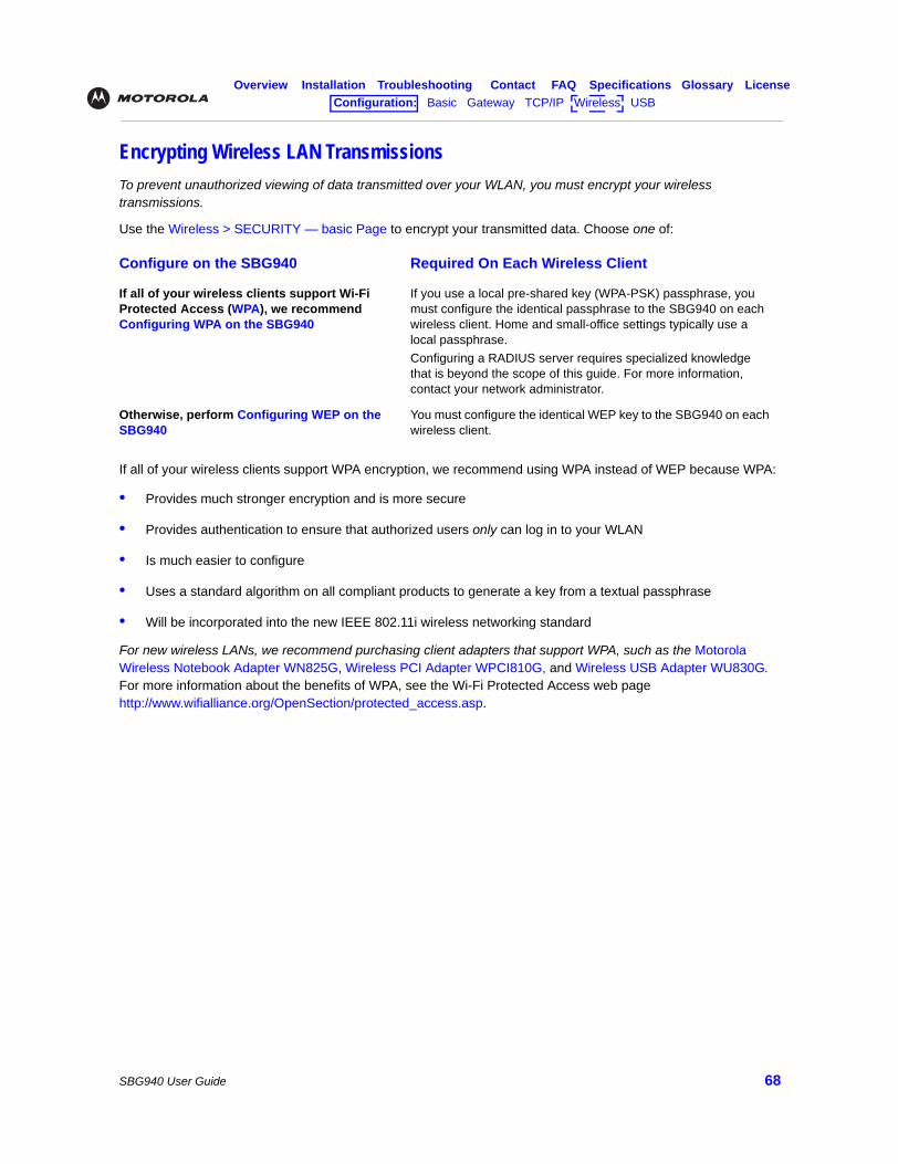
Overview Installation Troubleshooting Contact FAQ Specifications Glossary LicenseConfiguration: Basic Gateway TCP/IP Wireless USB
SBG940 User Guide 68
Encrypting Wireless LAN Transmissions To prevent unauthorized viewing of data transmitted over your WLAN, you must encrypt your wireless transmissions.
Use the Wireless > SECURITY — basic Page to encrypt your transmitted data. Choose one of:
If all of your wireless clients support WPA encryption, we recommend using WPA instead of WEP because WPA:
• Provides much stronger encryption and is more secure
• Provides authentication to ensure that authorized users only can log in to your WLAN
• Is much easier to configure
• Uses a standard algorithm on all compliant products to generate a key from a textual passphrase
• Will be incorporated into the new IEEE 802.11i wireless networking standard
For new wireless LANs, we recommend purchasing client adapters that support WPA, such as the Motorola Wireless Notebook Adapter WN825G, Wireless PCI Adapter WPCI810G, and Wireless USB Adapter WU830G. For more information about the benefits of WPA, see the Wi-Fi Protected Access web page http://www.wifialliance.org/OpenSection/protected_access.asp.
Configure on the SBG940 Required On Each Wireless Client
If all of your wireless clients support Wi-Fi Protected Access (WPA), we recommend Configuring WPA on the SBG940
If you use a local pre-shared key (WPA-PSK) passphrase, you must configure the identical passphrase to the SBG940 on each wireless client. Home and small-office settings typically use a local passphrase.Configuring a RADIUS server requires specialized knowledge that is beyond the scope of this guide. For more information, contact your network administrator.
Otherwise, perform Configuring WEP on the SBG940
You must configure the identical WEP key to the SBG940 on each wireless client.
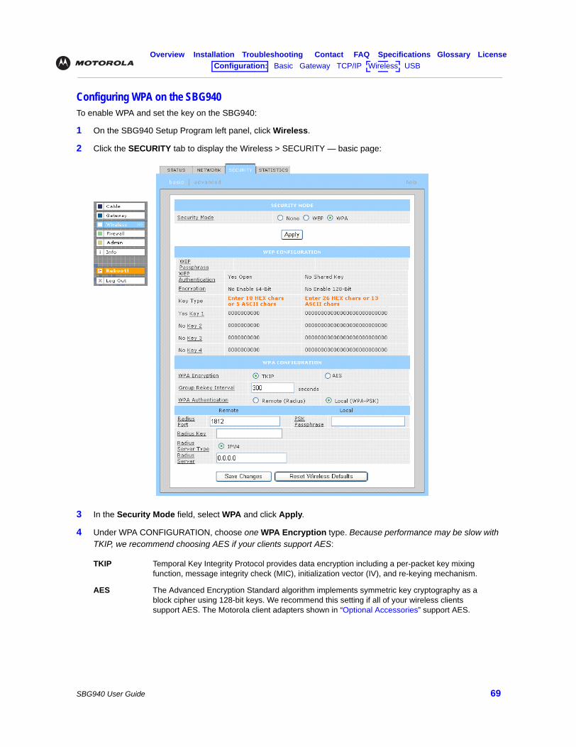
Overview Installation Troubleshooting Contact FAQ Specifications Glossary LicenseConfiguration: Basic Gateway TCP/IP Wireless USB
SBG940 User Guide 69
Configuring WPA on the SBG940To enable WPA and set the key on the SBG940:
1 On the SBG940 Setup Program left panel, click Wireless.
2 Click the SECURITY tab to display the Wireless > SECURITY — basic page:
3 In the Security Mode field, select WPA and click Apply.
4 Under WPA CONFIGURATION, choose one WPA Encryption type. Because performance may be slow with TKIP, we recommend choosing AES if your clients support AES:
TKIP Temporal Key Integrity Protocol provides data encryption including a per-packet key mixing function, message integrity check (MIC), initialization vector (IV), and re-keying mechanism.
AES The Advanced Encryption Standard algorithm implements symmetric key cryptography as a block cipher using 128-bit keys. We recommend this setting if all of your wireless clients support AES. The Motorola client adapters shown in “Optional Accessories” support AES.
Overview Installation Troubleshooting Contact FAQ Specifications Glossary LicenseConfiguration: Basic Gateway TCP/IP Wireless USB
SBG940 User Guide 70
5 Choose the WPA Authentication type:
6 For Remote (Radius) authentication only, set:
7 For Local (WPA-PSK) authentication only, set:
8 Click Save Changes.
If you need to restore the wireless defaults, click Reset Wireless Defaults.
Remote (Radius)
If a Remote Authentication Dial-In User Service (RADIUS) server is available, you can select this option and go to step 6. A RADIUS server is typically used in a large corporate location.
Local (WPA-PSK)
If you choose Pre-Shared Key (PSK) local authentication, if the passphrase on any client supporting WPA matches the PSK Passphrase set on the SBG940, the client can access the SBG940 WLAN. To set the PSK Passphrase, go to step 7. A local key is typically used in a home or small office.
Radius Port The port used for remote authentication through a RADIUS server. It can be from 0 to 65535.
Radius Key The key for remote authentication. It can be from 0 to 255 ASCII characters.
Radius Server Type
Currently IPv4 only.
Radius Server The RADIUS server IP address in dotted-decimal format (xxx.xxx.xxx.xxx).
PSK Passphrase
The PSK password containing from 8 to 63 ASCII characters. You must set the identical passphrase on each WLAN client (see “Configuring a Wireless Client for WPA”).
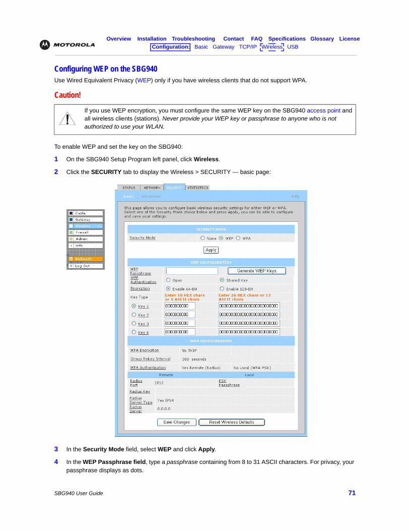
Overview Installation Troubleshooting Contact FAQ Specifications Glossary LicenseConfiguration: Basic Gateway TCP/IP Wireless USB
SBG940 User Guide 71
Configuring WEP on the SBG940Use Wired Equivalent Privacy (WEP) only if you have wireless clients that do not support WPA.
To enable WEP and set the key on the SBG940:
1 On the SBG940 Setup Program left panel, click Wireless.
2 Click the SECURITY tab to display the Wireless > SECURITY — basic page:
3 In the Security Mode field, select WEP and click Apply.
4 In the WEP Passphrase field, type a passphrase containing from 8 to 31 ASCII characters. For privacy, your passphrase displays as dots.
Caution!
If you use WEP encryption, you must configure the same WEP key on the SBG940 access point and all wireless clients (stations). Never provide your WEP key or passphrase to anyone who is not authorized to use your WLAN.
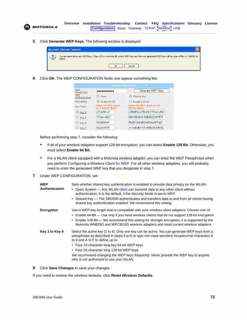
Overview Installation Troubleshooting Contact FAQ Specifications Glossary LicenseConfiguration: Basic Gateway TCP/IP Wireless USB
SBG940 User Guide 72
5 Click Generate WEP Keys. The following window is displayed:
6 Click OK. The WEP CONFIGURATION fields now appear something like:
Before performing step 7, consider the following:
• If all of your wireless adapters support 128-bit encryption, you can select Enable 128 Bit. Otherwise, you must select Enable 64 Bit.
• For a WLAN client equipped with a Motorola wireless adapter, you can enter the WEP Passphrase when you perform Configuring a Wireless Client for WEP. For all other wireless adapters, you will probably need to enter the generated WEP key that you designate in step 7.
7 Under WEP CONFIGURATION, set:
8 Click Save Changes to save your changes.
If you need to restore the wireless defaults, click Reset Wireless Defaults.
WEP Authentication
Sets whether shared key authentication is enabled to provide data privacy on the WLAN:• Open System — Any WLAN client can transmit data to any other client without
authentication. It is the default, if the Security Mode is set to WEP.• Shared Key — The SBG940 authenticates and transfers data to and from all clients having
shared key authentication enabled. We recommend this setting.
Encryption Use a WEP key length that is compatible with your wireless client adapters. Choose one of:• Enable 64-Bit — Use only if you have wireless clients that do not support 128-bit encryption• Enable 128-Bit — We recommend this setting for stronger encryption; it is supported by the
Motorola WN825G and WPCI810G wireless adapters and most current wireless adapters
Key 1 to Key 4 Select the active key (1 to 4). Only one key can be active. You can generate WEP keys from a passphrase as described in steps 4 to 6 or type non-case-sensitive hexadecimal characters 0 to 9 and A to F to define up to:• Four 10-character long key 64-bit WEP keys• Four 26-character long 128-bit WEP keysWe recommend changing the WEP keys frequently. Never provide the WEP key to anyone who is not authorized to use your WLAN.
Overview Installation Troubleshooting Contact FAQ Specifications Glossary LicenseConfiguration: Basic Gateway TCP/IP Wireless USB
SBG940 User Guide 73
Restricting Wireless LAN AccessThe default SBG940 wireless settings enable any computer having a compatible wireless adapter to access your WLAN. To protect your network from unauthorized intrusions, you can restrict access to your WLAN to a limited number of computers on the Wireless > SECURITY — advanced Page.
You can configure one or both of:
Configure on the SBG940 Required On Each Wireless Client
Perform Configuring the Wireless Network Name on the SBG940 to disable Extended Service Set Identifier (ESSID) broadcasting to enable closed network operation
You must configure the identical ESSID (network name) to the SBG940.
Perform Configuring a MAC Access Control List on the SBG940 to restrict access to wireless clients with known MAC addresses
No configuration is required on the client.
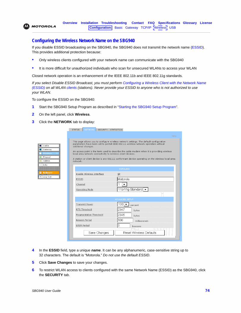
Overview Installation Troubleshooting Contact FAQ Specifications Glossary LicenseConfiguration: Basic Gateway TCP/IP Wireless USB
SBG940 User Guide 74
Configuring the Wireless Network Name on the SBG940If you disable ESSID broadcasting on the SBG940, the SBG940 does not transmit the network name (ESSID). This provides additional protection because:
• Only wireless clients configured with your network name can communicate with the SBG940
• It is more difficult for unauthorized individuals who scan for unsecured WLANs to access your WLAN
Closed network operation is an enhancement of the IEEE 802.11b and IEEE 802.11g standards.
If you select Disable ESSID Broadcast, you must perform Configuring a Wireless Client with the Network Name (ESSID) on all WLAN clients (stations). Never provide your ESSID to anyone who is not authorized to use your WLAN.
To configure the ESSID on the SBG940:
1 Start the SBG940 Setup Program as described in “Starting the SBG940 Setup Program”.
2 On the left panel, click Wireless.
3 Click the NETWORK tab to display:
4 In the ESSID field, type a unique name. It can be any alphanumeric, case-sensitive string up to 32 characters. The default is “Motorola.” Do not use the default ESSID.
5 Click Save Changes to save your changes.
6 To restrict WLAN access to clients configured with the same Network Name (ESSID) as the SBG940, click the SECURITY tab.
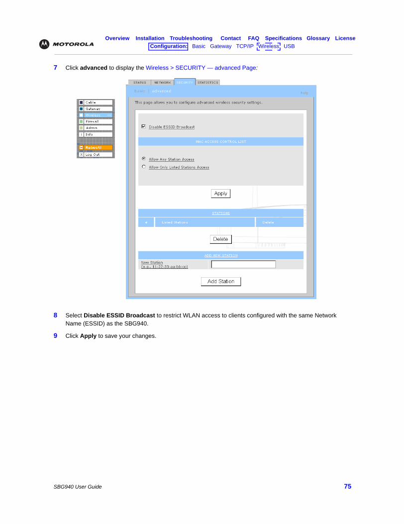
Overview Installation Troubleshooting Contact FAQ Specifications Glossary LicenseConfiguration: Basic Gateway TCP/IP Wireless USB
SBG940 User Guide 75
7 Click advanced to display the Wireless > SECURITY — advanced Page:
8 Select Disable ESSID Broadcast to restrict WLAN access to clients configured with the same Network Name (ESSID) as the SBG940.
9 Click Apply to save your changes.
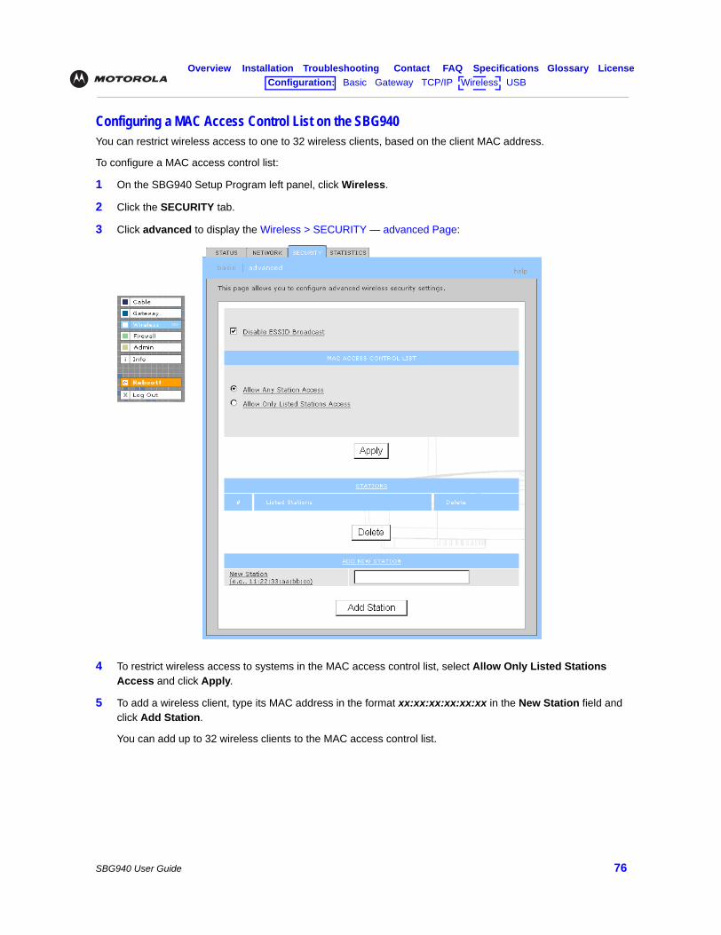
Overview Installation Troubleshooting Contact FAQ Specifications Glossary LicenseConfiguration: Basic Gateway TCP/IP Wireless USB
SBG940 User Guide 76
Configuring a MAC Access Control List on the SBG940You can restrict wireless access to one to 32 wireless clients, based on the client MAC address.
To configure a MAC access control list:
1 On the SBG940 Setup Program left panel, click Wireless.
2 Click the SECURITY tab.
3 Click advanced to display the Wireless > SECURITY — advanced Page:
4 To restrict wireless access to systems in the MAC access control list, select Allow Only Listed Stations Access and click Apply.
5 To add a wireless client, type its MAC address in the format xx:xx:xx:xx:xx:xx in the New Station field and click Add Station.
You can add up to 32 wireless clients to the MAC access control list.
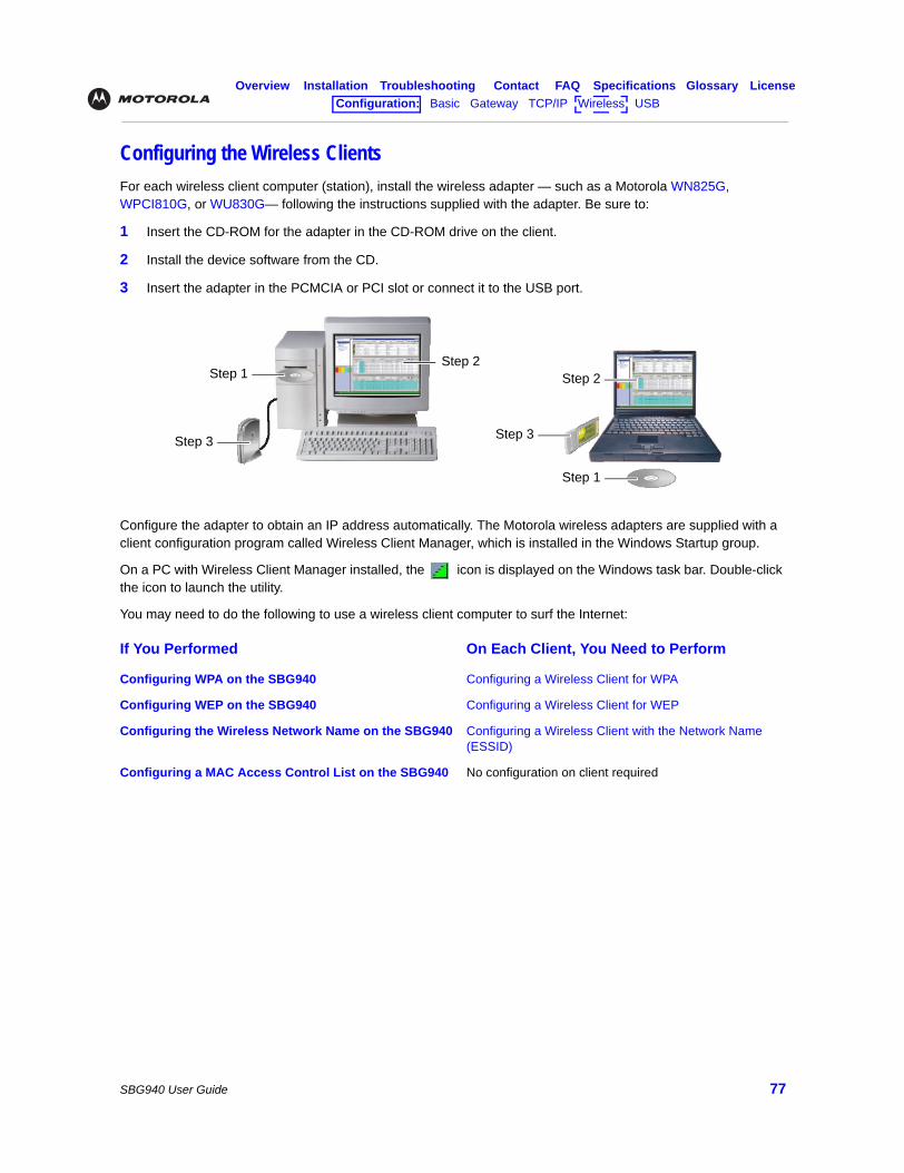
Overview Installation Troubleshooting Contact FAQ Specifications Glossary LicenseConfiguration: Basic Gateway TCP/IP Wireless USB
SBG940 User Guide 77
Configuring the Wireless ClientsFor each wireless client computer (station), install the wireless adapter — such as a Motorola WN825G, WPCI810G, or WU830G— following the instructions supplied with the adapter. Be sure to:
1 Insert the CD-ROM for the adapter in the CD-ROM drive on the client.
2 Install the device software from the CD.
3 Insert the adapter in the PCMCIA or PCI slot or connect it to the USB port.
Configure the adapter to obtain an IP address automatically. The Motorola wireless adapters are supplied with a client configuration program called Wireless Client Manager, which is installed in the Windows Startup group.
On a PC with Wireless Client Manager installed, the icon is displayed on the Windows task bar. Double-click the icon to launch the utility.
You may need to do the following to use a wireless client computer to surf the Internet:
If You Performed On Each Client, You Need to Perform
Configuring WPA on the SBG940 Configuring a Wireless Client for WPA
Configuring WEP on the SBG940 Configuring a Wireless Client for WEP
Configuring the Wireless Network Name on the SBG940 Configuring a Wireless Client with the Network Name (ESSID)
Configuring a MAC Access Control List on the SBG940 No configuration on client required
Step 1
Step 1
Step 2Step 2
Step 3Step 3
Overview Installation Troubleshooting Contact FAQ Specifications Glossary LicenseConfiguration: Basic Gateway TCP/IP Wireless USB
SBG940 User Guide 78
Configuring a Wireless Client for WPAIf you enabled WPA and set a PSK Passphrase by Configuring WPA on the SBG940, you must configure the same passphrase (key) on each wireless client. The SBG940 cannot authenticate a client if:
• WPA is enabled on the SBG940 but not on the client
• The client passphrase does not match the SBG940 PSK Passphrase
For information about the WPA support in Windows XP, visit:
You can download the Microsoft Windows XP Support Patch for Wi-Fi Protected Access from http://www.microsoft.com/downloads/details.aspx?FamilyId=009D8425-CE2B-47A4-ABEC-274845DC9E91&displaylang=en
Configuring a Wireless Client for WEPIf you enabled WEP and set a key by Configuring WEP on the SBG940, you must configure the same WEP key on each wireless client. The SBG940 cannot authenticate a client if:
• Shared Key Authentication is enabled on the SBG940 but not on the client
• The client WEP key does not match the SBG940 WEP key
On a WLAN client equipped with a Motorola wireless adapter, you can enter the WEP Passphrase you set when you configured the SBG940. For all other wireless adapters, you must enter the 64-bit or 128-bit WEP key generated by the SBG940.
Configuring a Wireless Client with the Network Name (ESSID)To distinguish it from other nearby WLANs, you can identify your WLAN with a unique network name (also known as a network identifier or ESSID). When prompted for the network identifier, network name, or ESSID, type the name set in the ESSID field on the Wireless > NETWORK Page in the SBG940 Setup Program. For more information, see “Configuring the Wireless Network Name on the SBG940”.
After you specify the network name, many wireless cards or adapters automatically scan for an access point such as the SBG940 and the proper channel and data rate. If your card requires you to manually start scanning for an access point, do so following the instructions in the documentation supplied with the card.
WPA Wireless Security for Home Networks http://www.microsoft.com/WindowsXP/expertzone/columns/ bowman/03july28.asp
Overview of the WPA Wireless Security Update in Windows XP
http://support.microsoft.com/?kbid=815485
Caution!
Never provide the PSK Passphrase to anyone who is not authorized to use your WLAN.
Caution!
Never provide the WEP key to anyone who is not authorized to use your WLAN.
Overview Installation Troubleshooting Contact FAQ Specifications Glossary LicenseConfiguration: Basic Gateway TCP/IP Wireless USB
SBG940 User Guide 79
Wireless Pages in the SBG940 Setup ProgramUse the Wireless pages to control and monitor the wireless interface:
• Wireless > STATUS Page
• Wireless > NETWORK Page
• Wireless > SECURITY — basic Page
• Wireless > SECURITY — advanced Page
• Wireless > STATISTICS page
After you edit some fields and click Apply, you are warned that you must reboot your SBG940 for your change to take effect. Rebooting takes 10 to 15 seconds. After rebooting, you must log in again.
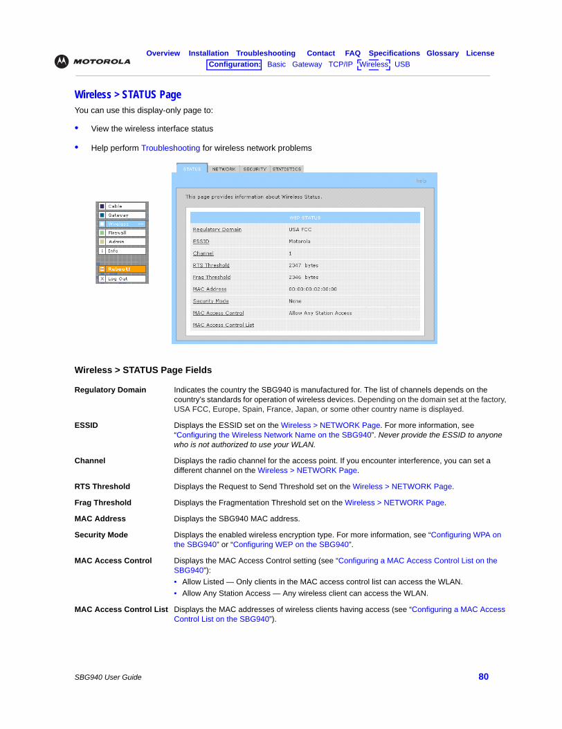
Overview Installation Troubleshooting Contact FAQ Specifications Glossary LicenseConfiguration: Basic Gateway TCP/IP Wireless USB
SBG940 User Guide 80
Wireless > STATUS PageYou can use this display-only page to:
• View the wireless interface status
• Help perform Troubleshooting for wireless network problems
Wireless > STATUS Page Fields
Regulatory Domain Indicates the country the SBG940 is manufactured for. The list of channels depends on the country’s standards for operation of wireless devices. Depending on the domain set at the factory, USA FCC, Europe, Spain, France, Japan, or some other country name is displayed.
ESSID Displays the ESSID set on the Wireless > NETWORK Page. For more information, see “Configuring the Wireless Network Name on the SBG940”. Never provide the ESSID to anyone who is not authorized to use your WLAN.
Channel Displays the radio channel for the access point. If you encounter interference, you can set a different channel on the Wireless > NETWORK Page.
RTS Threshold Displays the Request to Send Threshold set on the Wireless > NETWORK Page.
Frag Threshold Displays the Fragmentation Threshold set on the Wireless > NETWORK Page.
MAC Address Displays the SBG940 MAC address.
Security Mode Displays the enabled wireless encryption type. For more information, see “Configuring WPA on the SBG940” or “Configuring WEP on the SBG940”.
MAC Access Control Displays the MAC Access Control setting (see “Configuring a MAC Access Control List on the SBG940”):• Allow Listed — Only clients in the MAC access control list can access the WLAN.• Allow Any Station Access — Any wireless client can access the WLAN.
MAC Access Control List Displays the MAC addresses of wireless clients having access (see “Configuring a MAC Access Control List on the SBG940”).
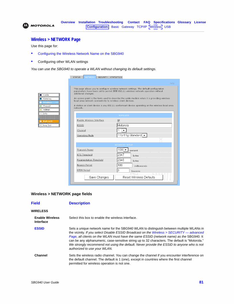
Overview Installation Troubleshooting Contact FAQ Specifications Glossary LicenseConfiguration: Basic Gateway TCP/IP Wireless USB
SBG940 User Guide 81
Wireless > NETWORK PageUse this page for:
• Configuring the Wireless Network Name on the SBG940
• Configuring other WLAN settings
You can use the SBG940 to operate a WLAN without changing its default settings.
Wireless > NETWORK page fields
Field Description
WIRELESS
Enable Wireless Interface
Select this box to enable the wireless interface.
ESSID Sets a unique network name for the SBG940 WLAN to distinguish between multiple WLANs in the vicinity. If you select Disable ESSID Broadcast on the Wireless > SECURITY — advanced Page, all clients on the WLAN must have the same ESSID (network name) as the SBG940. It can be any alphanumeric, case-sensitive string up to 32 characters. The default is “Motorola.” We strongly recommend not using the default. Never provide the ESSID to anyone who is not authorized to use your WLAN.
Channel Sets the wireless radio channel. You can change the channel if you encounter interference on the default channel. The default is 1 (one), except in countries where the first channel permitted for wireless operation is not one.
Overview Installation Troubleshooting Contact FAQ Specifications Glossary LicenseConfiguration: Basic Gateway TCP/IP Wireless USB
SBG940 User Guide 82
Operating Mode Sets how the SBG940 communicates with wireless clients (stations):• 11b/11g Standard — Enables all IEEE 802.11b and IEEE 802.11g clients to work with the
SBG940. We recommend using this default setting in most cases because it is more flexible. • 11g Enhanced — Choose this option only if all IEEE 802.11g client adapters on the network
support the performance-enhancing features of the IEEE 11g Enhanced mode. It is not supported by all IEEE 802.11g adapters.
ADVANCED SETUP
Transmit Power Sets the SBG940 wireless transmission power — 3, 6, 12, 25, 50, 75, or 100%. The default is 100%. You can turn down the Transmit Power to:• Decrease “leakage” into outside areas such as the street• Improve performance if you usually position your computer or laptop close to your SBG940Transmission power control is an optional IEEE 802.11 feature.
RTS Threshold The Request To Send Threshold sets the minimum packet size for which the SBG940 issues an RTS before sending a packet. A low RTS Threshold can help when many clients are associated with the SBG940 or the clients are far apart and can detect the SBG940 but not each other. It can be 0 to 2347 bytes. The default is 2347.
Fragmentation Threshold
Sets the size at which packets are fragmented (sent as several packets instead of as one packet). A low Fragmentation Threshold can help when communication is poor or there is a significant interference. It can be 256 to 2346 bytes. The default is 2346.
Beacon Period Sets the time between beacon frames sent by the SBG940 for wireless network synchronization. It can be from 1 to 999 ms. The default is 100 ms.
DTIM Period The delivery traffic indication message (DTIM) period is the number of Beacon Periods that elapse before a wireless client operating in power save mode “listens” for buffered broadcast or multicast messages from the SBG940. It can be from 1 to 99999. The default is 3.
Wireless > NETWORK page fields (continued)
Field Description
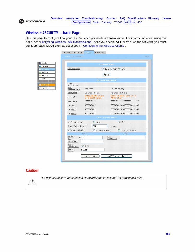
Overview Installation Troubleshooting Contact FAQ Specifications Glossary LicenseConfiguration: Basic Gateway TCP/IP Wireless USB
SBG940 User Guide 83
Wireless > SECURITY — basic PageUse this page to configure how your SBG940 encrypts wireless transmissions. For information about using this page, see “Encrypting Wireless LAN Transmissions”. After you enable WEP or WPA on the SBG940, you must configure each WLAN client as described in “Configuring the Wireless Clients”.
Caution!
The default Security Mode setting None provides no security for transmitted data.
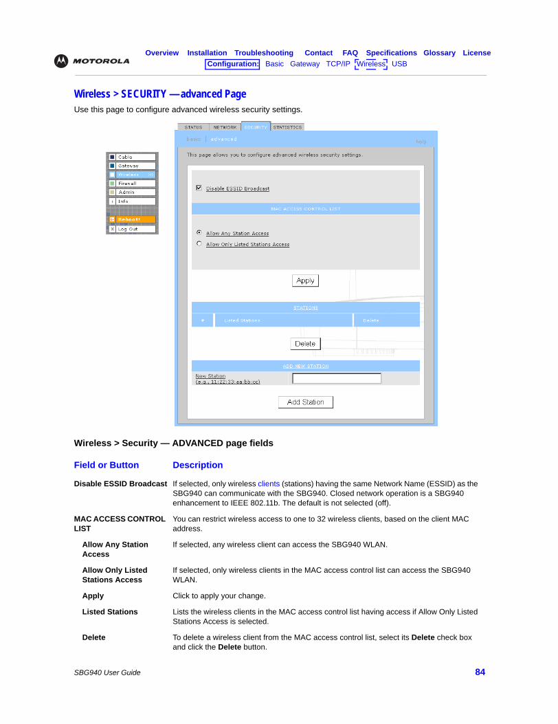
Overview Installation Troubleshooting Contact FAQ Specifications Glossary LicenseConfiguration: Basic Gateway TCP/IP Wireless USB
SBG940 User Guide 84
Wireless > SECURITY — advanced PageUse this page to configure advanced wireless security settings.
Wireless > Security — ADVANCED page fields
Field or Button Description
Disable ESSID Broadcast If selected, only wireless clients (stations) having the same Network Name (ESSID) as the SBG940 can communicate with the SBG940. Closed network operation is a SBG940 enhancement to IEEE 802.11b. The default is not selected (off).
MAC ACCESS CONTROL LIST
You can restrict wireless access to one to 32 wireless clients, based on the client MAC address.
Allow Any Station Access
If selected, any wireless client can access the SBG940 WLAN.
Allow Only Listed Stations Access
If selected, only wireless clients in the MAC access control list can access the SBG940 WLAN.
Apply Click to apply your change.
Listed Stations Lists the wireless clients in the MAC access control list having access if Allow Only Listed Stations Access is selected.
Delete To delete a wireless client from the MAC access control list, select its Delete check box and click the Delete button.
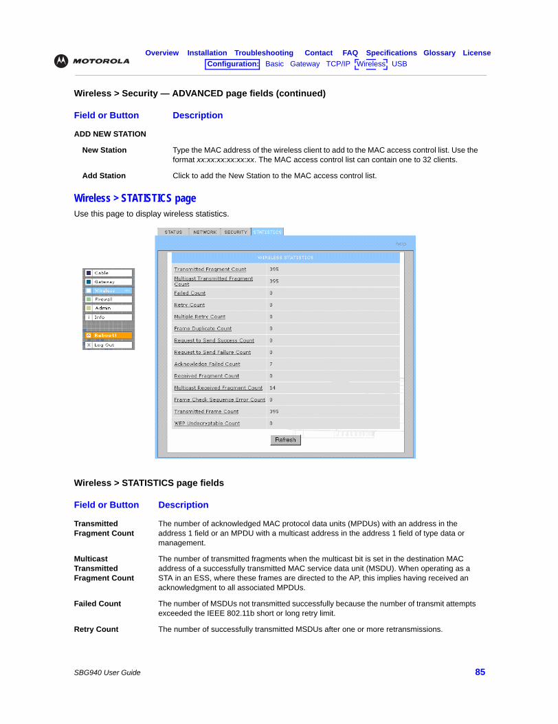
Overview Installation Troubleshooting Contact FAQ Specifications Glossary LicenseConfiguration: Basic Gateway TCP/IP Wireless USB
SBG940 User Guide 85
Wireless > STATISTICS pageUse this page to display wireless statistics.
ADD NEW STATION
New Station Type the MAC address of the wireless client to add to the MAC access control list. Use the format xx:xx:xx:xx:xx:xx. The MAC access control list can contain one to 32 clients.
Add Station Click to add the New Station to the MAC access control list.
Wireless > STATISTICS page fields
Field or Button Description
Transmitted Fragment Count
The number of acknowledged MAC protocol data units (MPDUs) with an address in the address 1 field or an MPDU with a multicast address in the address 1 field of type data or management.
Multicast Transmitted Fragment Count
The number of transmitted fragments when the multicast bit is set in the destination MAC address of a successfully transmitted MAC service data unit (MSDU). When operating as a STA in an ESS, where these frames are directed to the AP, this implies having received an acknowledgment to all associated MPDUs.
Failed Count The number of MSDUs not transmitted successfully because the number of transmit attempts exceeded the IEEE 802.11b short or long retry limit.
Retry Count The number of successfully transmitted MSDUs after one or more retransmissions.
Wireless > Security — ADVANCED page fields (continued)
Field or Button Description
Overview Installation Troubleshooting Contact FAQ Specifications Glossary LicenseConfiguration: Basic Gateway TCP/IP Wireless USB
SBG940 User Guide 86
Multiple Retry Count The number of successfully transmitted MSDUs after more than one retransmission.
Frame Duplicate Count
The number of frames received where the Sequence Control field indicated the frame was a duplicate.
Request To Send Success Count
The number of CTS messages received in response to RTS messages.
Request To Send Failure Count
The number of CTS messages not received in response to RTS messages.
Acknowledge Failed Count
The number of acknowledgment messages not received when expected from a data message transmission.
Received Fragment Count
The number of successfully received MPDUs of type Data or Management.
Multicast Received Fragment Count
The number of MSDUs received when the multicast bit was set in the destination MAC address.
Frame Check Sequence Error Count
The number of FCS errors detected in a received MPDU.
Transmitted Frame Count
The number of successfully transmitted MSDUs.
WEP Undecryptable Count
This number of frames received with the WEP subfield of the Frame Control field set to one and the WEP On key value mapped to the client MAC address. This indicates that the frame should not have been encrypted or was discarded due to the receiving client not having WEP enabled.
Refresh Click to collect new data.
Wireless > STATISTICS page fields (continued)
Field or Button Description
Overview Installation Troubleshooting Contact FAQ Specifications Glossary LicenseConfiguration: Basic Gateway TCP/IP Wireless USB
SBG940 User Guide 87
TroubleshootingIf the solutions listed here do not solve your problem, contact your cable provider. Before calling your cable provider, try pressing the reset button on the rear panel. Resetting the SBG940 may take 5 to 30 minutes. Your service provider may ask for the status of the lights as described in “Front-Panel Lights and Error Conditions”.
Problem Possible Solutions
Power light is off
Check that the SBG940 is properly plugged into the electrical outlet.Check that the electrical outlet is working.Press the Reset button.
Cannot send or receive data
On the top front panel, note which is the first light (starting from the left) that is off. This light indicates where the error occurred as described in “Front-Panel Lights and Error Conditions.”If you have cable TV, check that the TV is working and the picture is clear. If you cannot receive regular TV channels, the data service will not function.Check the coaxial cable at the SBG940 and wall outlet. Hand-tighten if necessary.Check the IP address. Follow the steps for verifying the IP address for your system. See “Configuring TCP/IP”. Call your cable provider if you need an IP address.Check that the Ethernet cable is properly connected to the SBG940 and the computer.
Problems related to unsuccessful USB driver installation
Remove the USB driver. Follow the appropriate procedure for your system in “Setting Up a USB Driver”.
The SBG940 Setup Program will not start
The web cache is full or close to full. In Internet Explorer, choose Internet Options from the Tools menu, and click the General tab. Click Delete Files and Clear History. Then try Starting the SBG940 Setup Program again.
A wireless client(s) cannot send or receive data
Perform the first four checks in “Cannot send or receive data.”
Check the Security Mode setting on the Wireless > SECURITY — basic Page:• If you enabled WPA and configured a passphrase on the SBG940, be sure each affected
wireless client has the identical passphrase. If this does not solve the problem, check whether the wireless client supports WPA.
• If you enabled WEP and configured a key on the SBG940, be sure each affected wireless client has the identical WEP key. If this does not solve the problem, check whether the client wireless adapter supports the type of WEP key configured on the SBG940.
• To temporarily eliminate the Security Mode as a potential issue, select None and click Apply. After resolving your problem, be sure to re-enable wireless security.
On the Wireless > SECURITY — advanced Page:• Check whether you turned on Disable ESSID Broadcast. If it is on, be sure the network
name (ESSID) on each affected wireless client is identical to the ESSID on the SBG940.• Check whether you enabled Allow Only Listed Stations Access. If you did, be sure the
MAC address for each affected wireless client is correctly listed.
For detailed information, see “Setting Up Your Wireless LAN”.
Slow wireless transmission speed with WPA enabled
On the Wireless > SECURITY — basic Page, check whether the WPA Encryption type is TKIP. If all of your wireless clients support AES, change the WPA Encryption to AES as described in step 4 in “Configuring WPA on the SBG940”.
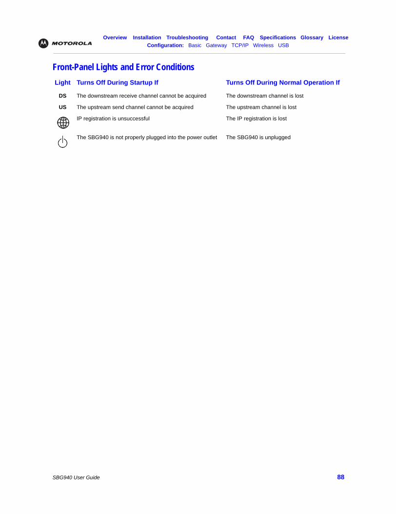
Overview Installation Troubleshooting Contact FAQ Specifications Glossary LicenseConfiguration: Basic Gateway TCP/IP Wireless USB
SBG940 User Guide 88
Front-Panel Lights and Error ConditionsLight Turns Off During Startup If Turns Off During Normal Operation If
DS The downstream receive channel cannot be acquired The downstream channel is lost
US The upstream send channel cannot be acquired The upstream channel is lost
IP registration is unsuccessful The IP registration is lost
The SBG940 is not properly plugged into the power outlet The SBG940 is unplugged

Overview Installation Troubleshooting Contact FAQ Specifications Glossary LicenseConfiguration: Basic Gateway TCP/IP Wireless USB
SBG940 User Guide 89
Setting Up a USB DriverThe following subsections describe setting up a USB driver if you connect a PC to the USB port on the SBG940. Before connecting a PC to the USB port, perform the appropriate procedure for your Windows version:
• Setting Up a USB Driver in Windows 98 Second Edition
• Setting Up a USB Driver in Windows 2000
• Setting Up a USB Driver in Windows Me
• Setting Up a USB Driver in Windows XP
The SBG940 USB driver does not support Macintosh or UNIX computers. For those systems, you can connect through Ethernet only.
If you have a problem setting up the USB driver, remove it by performing one of:
• Removing the USB Driver from Windows 98 Second Edition or Windows Me
• Removing the USB Driver from Windows 2000
• Removing the USB Driver from Windows XP
Then perform “Running the Motorola USB Driver Removal Utility” on page 107.
Caution!
Be sure the SBG940 Installation CD-ROM is inserted in the CD-ROM drive before you plug in the USB cable.
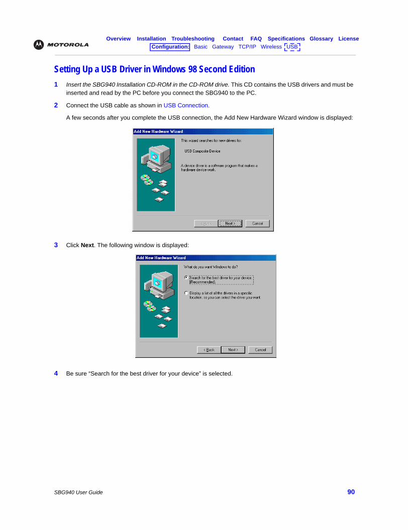
Overview Installation Troubleshooting Contact FAQ Specifications Glossary LicenseConfiguration: Basic Gateway TCP/IP Wireless USB
SBG940 User Guide 90
Setting Up a USB Driver in Windows 98 Second Edition1 Insert the SBG940 Installation CD-ROM in the CD-ROM drive. This CD contains the USB drivers and must be
inserted and read by the PC before you connect the SBG940 to the PC.
2 Connect the USB cable as shown in USB Connection.
A few seconds after you complete the USB connection, the Add New Hardware Wizard window is displayed:
3 Click Next. The following window is displayed:
4 Be sure “Search for the best driver for your device” is selected.
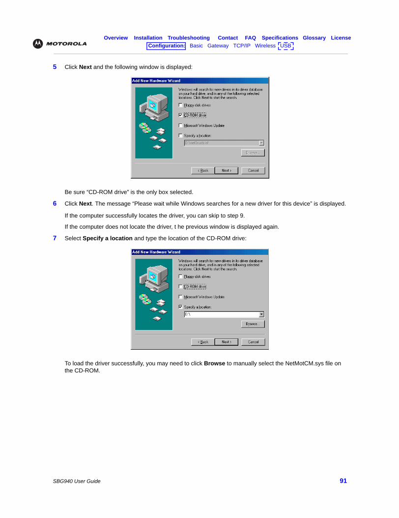
Overview Installation Troubleshooting Contact FAQ Specifications Glossary LicenseConfiguration: Basic Gateway TCP/IP Wireless USB
SBG940 User Guide 91
5 Click Next and the following window is displayed:
Be sure “CD-ROM drive” is the only box selected.
6 Click Next. The message “Please wait while Windows searches for a new driver for this device” is displayed.
If the computer successfully locates the driver, you can skip to step 9.
If the computer does not locate the driver, t he previous window is displayed again.
7 Select Specify a location and type the location of the CD-ROM drive:
To load the driver successfully, you may need to click Browse to manually select the NetMotCM.sys file on the CD-ROM.
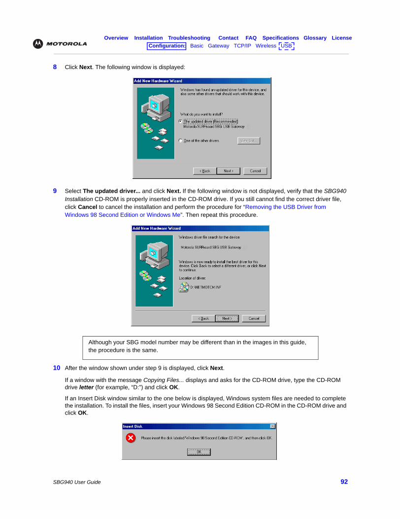
Overview Installation Troubleshooting Contact FAQ Specifications Glossary LicenseConfiguration: Basic Gateway TCP/IP Wireless USB
SBG940 User Guide 92
8 Click Next. The following window is displayed:
9 Select The updated driver... and click Next. If the following window is not displayed, verify that the SBG940 Installation CD-ROM is properly inserted in the CD-ROM drive. If you still cannot find the correct driver file, click Cancel to cancel the installation and perform the procedure for “Removing the USB Driver from Windows 98 Second Edition or Windows Me”. Then repeat this procedure.
10 After the window shown under step 9 is displayed, click Next.
If a window with the message Copying Files... displays and asks for the CD-ROM drive, type the CD-ROM drive letter (for example, “D:”) and click OK.
If an Insert Disk window similar to the one below is displayed, Windows system files are needed to complete the installation. To install the files, insert your Windows 98 Second Edition CD-ROM in the CD-ROM drive and click OK.
Although your SBG model number may be different than in the images in this guide, the procedure is the same.
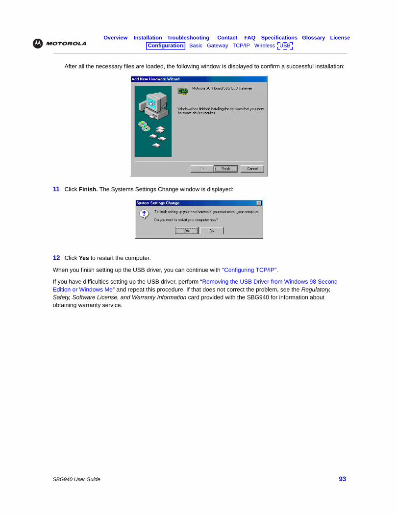
Overview Installation Troubleshooting Contact FAQ Specifications Glossary LicenseConfiguration: Basic Gateway TCP/IP Wireless USB
SBG940 User Guide 93
After all the necessary files are loaded, the following window is displayed to confirm a successful installation:
11 Click Finish. The Systems Settings Change window is displayed:
12 Click Yes to restart the computer.
When you finish setting up the USB driver, you can continue with “Configuring TCP/IP”.
If you have difficulties setting up the USB driver, perform “Removing the USB Driver from Windows 98 Second Edition or Windows Me” and repeat this procedure. If that does not correct the problem, see the Regulatory, Safety, Software License, and Warranty Information card provided with the SBG940 for information about obtaining warranty service.
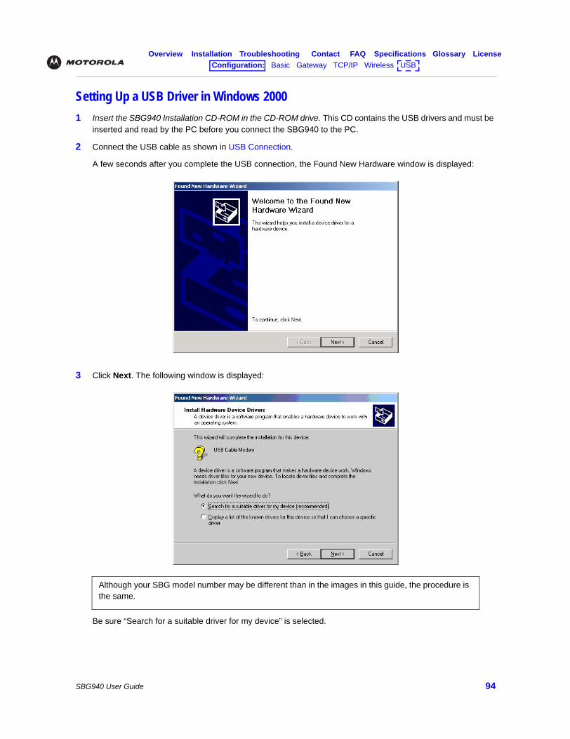
Overview Installation Troubleshooting Contact FAQ Specifications Glossary LicenseConfiguration: Basic Gateway TCP/IP Wireless USB
SBG940 User Guide 94
Setting Up a USB Driver in Windows 20001 Insert the SBG940 Installation CD-ROM in the CD-ROM drive. This CD contains the USB drivers and must be
inserted and read by the PC before you connect the SBG940 to the PC.
2 Connect the USB cable as shown in USB Connection.
A few seconds after you complete the USB connection, the Found New Hardware window is displayed:
3 Click Next. The following window is displayed:
Be sure “Search for a suitable driver for my device” is selected.
Although your SBG model number may be different than in the images in this guide, the procedure is the same.
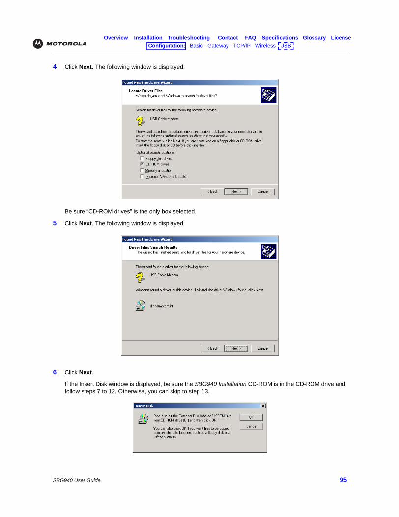
Overview Installation Troubleshooting Contact FAQ Specifications Glossary LicenseConfiguration: Basic Gateway TCP/IP Wireless USB
SBG940 User Guide 95
4 Click Next. The following window is displayed:
Be sure “CD-ROM drives” is the only box selected.
5 Click Next. The following window is displayed:
6 Click Next.
If the Insert Disk window is displayed, be sure the SBG940 Installation CD-ROM is in the CD-ROM drive and follow steps 7 to 12. Otherwise, you can skip to step 13.
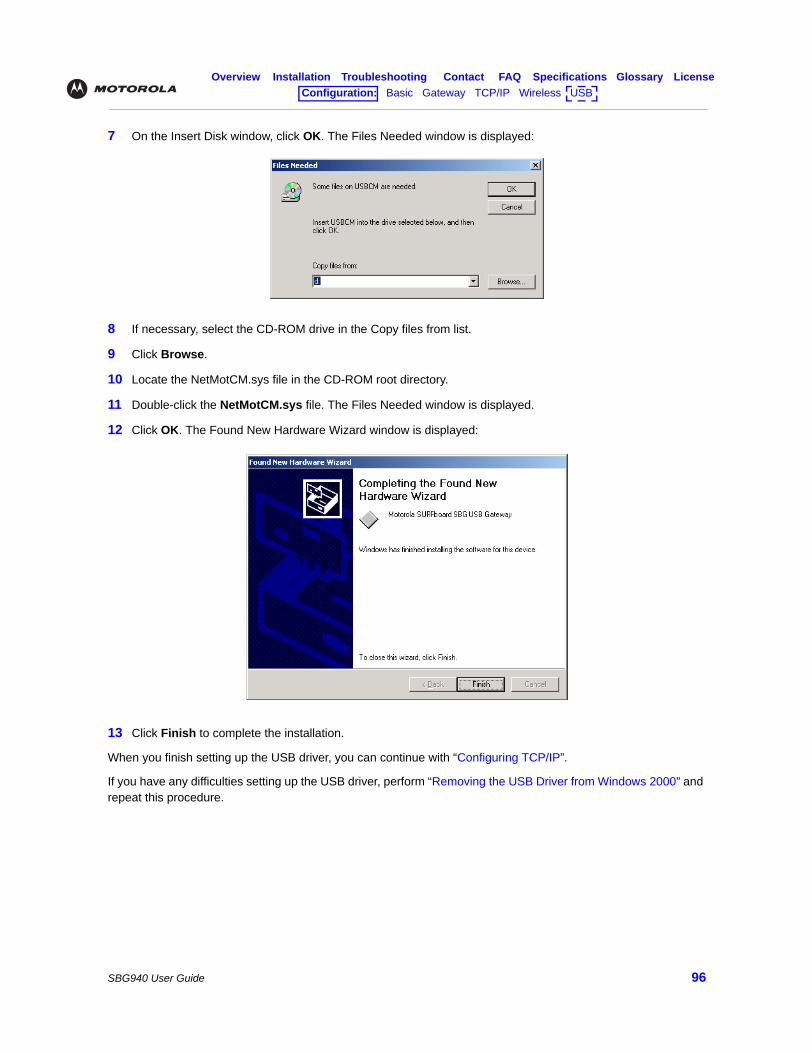
Overview Installation Troubleshooting Contact FAQ Specifications Glossary LicenseConfiguration: Basic Gateway TCP/IP Wireless USB
SBG940 User Guide 96
7 On the Insert Disk window, click OK. The Files Needed window is displayed:
8 If necessary, select the CD-ROM drive in the Copy files from list.
9 Click Browse.
10 Locate the NetMotCM.sys file in the CD-ROM root directory.
11 Double-click the NetMotCM.sys file. The Files Needed window is displayed.
12 Click OK. The Found New Hardware Wizard window is displayed:
13 Click Finish to complete the installation.
When you finish setting up the USB driver, you can continue with “Configuring TCP/IP”.
If you have any difficulties setting up the USB driver, perform “Removing the USB Driver from Windows 2000” and repeat this procedure.
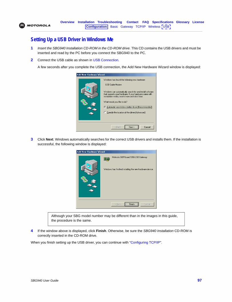
Overview Installation Troubleshooting Contact FAQ Specifications Glossary LicenseConfiguration: Basic Gateway TCP/IP Wireless USB
SBG940 User Guide 97
Setting Up a USB Driver in Windows Me1 Insert the SBG940 Installation CD-ROM in the CD-ROM drive. This CD contains the USB drivers and must be
inserted and read by the PC before you connect the SBG940 to the PC.
2 Connect the USB cable as shown in USB Connection.
A few seconds after you complete the USB connection, the Add New Hardware Wizard window is displayed:
3 Click Next. Windows automatically searches for the correct USB drivers and installs them. If the installation is successful, the following window is displayed:
4 If the window above is displayed, click Finish. Otherwise, be sure the SBG940 Installation CD-ROM is correctly inserted in the CD-ROM drive.
When you finish setting up the USB driver, you can continue with “Configuring TCP/IP”.
Although your SBG model number may be different than in the images in this guide, the procedure is the same.
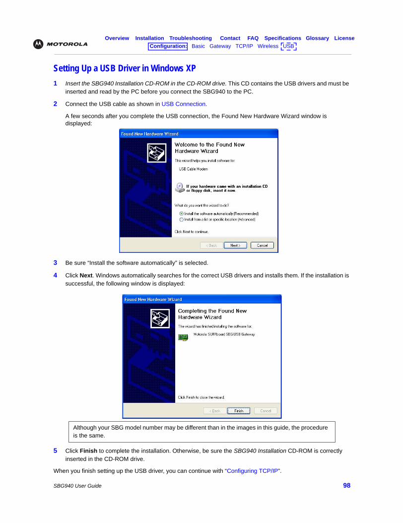
Overview Installation Troubleshooting Contact FAQ Specifications Glossary LicenseConfiguration: Basic Gateway TCP/IP Wireless USB
SBG940 User Guide 98
Setting Up a USB Driver in Windows XP1 Insert the SBG940 Installation CD-ROM in the CD-ROM drive. This CD contains the USB drivers and must be
inserted and read by the PC before you connect the SBG940 to the PC.
2 Connect the USB cable as shown in USB Connection.
A few seconds after you complete the USB connection, the Found New Hardware Wizard window is displayed:
3 Be sure “Install the software automatically” is selected.
4 Click Next. Windows automatically searches for the correct USB drivers and installs them. If the installation is successful, the following window is displayed:
5 Click Finish to complete the installation. Otherwise, be sure the SBG940 Installation CD-ROM is correctly inserted in the CD-ROM drive.
When you finish setting up the USB driver, you can continue with “Configuring TCP/IP”.
Although your SBG model number may be different than in the images in this guide, the procedure is the same.
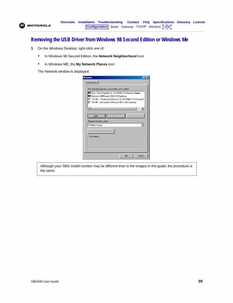
Overview Installation Troubleshooting Contact FAQ Specifications Glossary LicenseConfiguration: Basic Gateway TCP/IP Wireless USB
SBG940 User Guide 99
Removing the USB Driver from Windows 98 Second Edition or Windows Me 1 On the Windows Desktop, right-click one of:
• In Windows 98 Second Edition, the Network Neighborhood icon
• In Windows ME, the My Network Places icon
The Network window is displayed:
Although your SBG model number may be different than in the images in this guide, the procedure is the same.
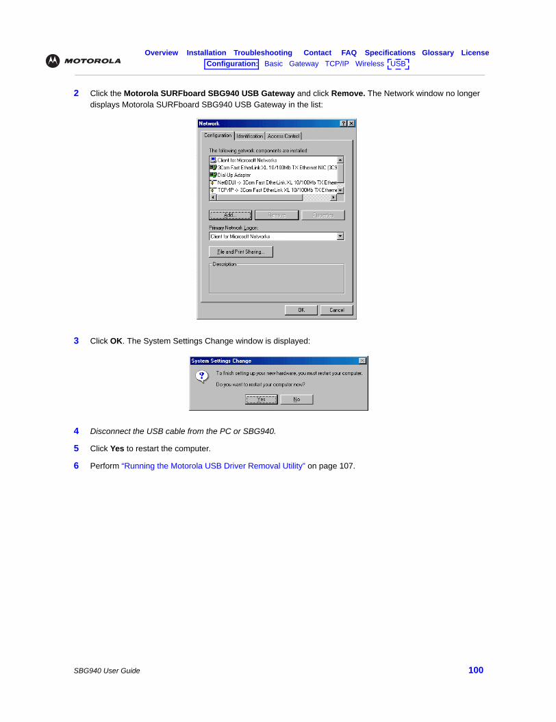
Overview Installation Troubleshooting Contact FAQ Specifications Glossary LicenseConfiguration: Basic Gateway TCP/IP Wireless USB
SBG940 User Guide 100
2 Click the Motorola SURFboard SBG940 USB Gateway and click Remove. The Network window no longer displays Motorola SURFboard SBG940 USB Gateway in the list:
3 Click OK. The System Settings Change window is displayed:
4 Disconnect the USB cable from the PC or SBG940.
5 Click Yes to restart the computer.
6 Perform “Running the Motorola USB Driver Removal Utility” on page 107.
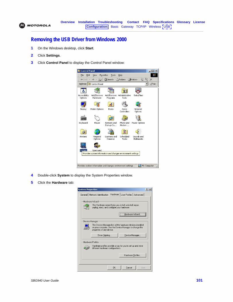
Overview Installation Troubleshooting Contact FAQ Specifications Glossary LicenseConfiguration: Basic Gateway TCP/IP Wireless USB
SBG940 User Guide 101
Removing the USB Driver from Windows 20001 On the Windows desktop, click Start.
2 Click Settings.
3 Click Control Panel to display the Control Panel window:
4 Double-click System to display the System Properties window.
5 Click the Hardware tab:
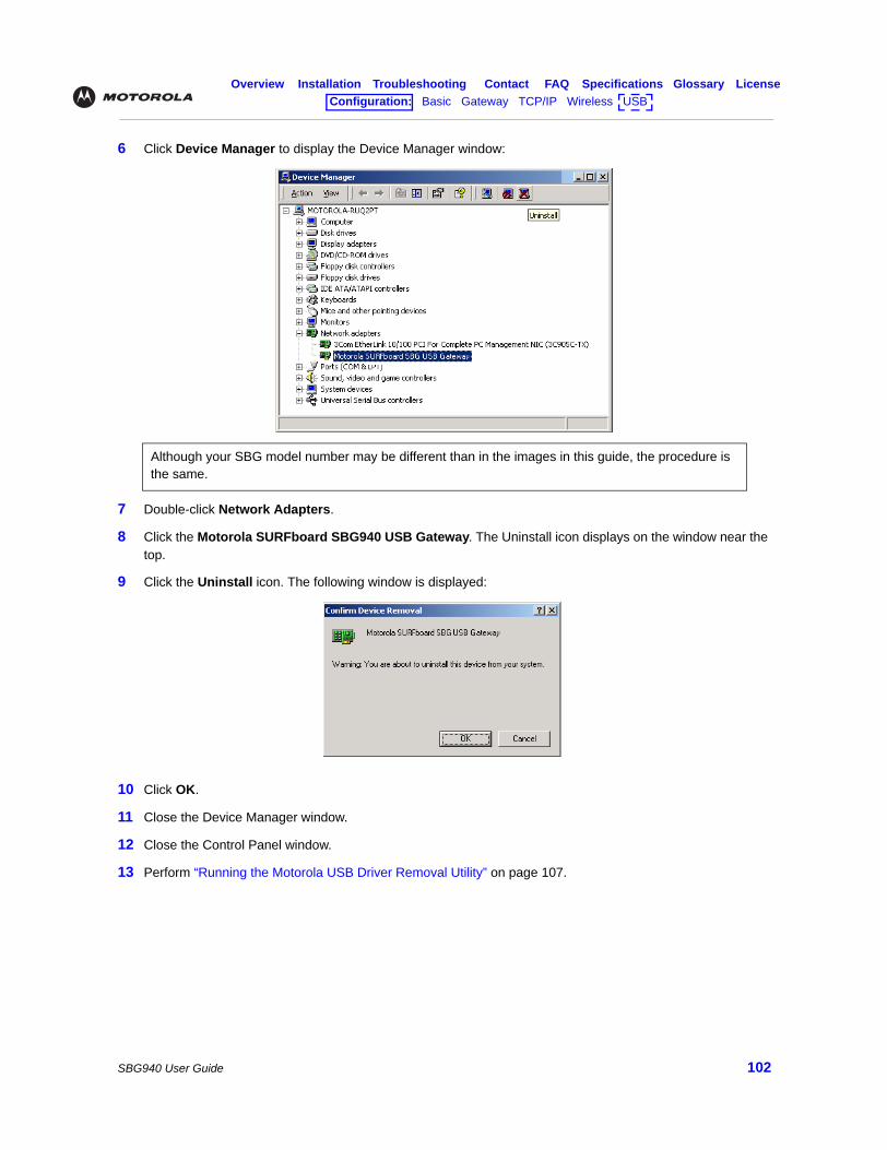
Overview Installation Troubleshooting Contact FAQ Specifications Glossary LicenseConfiguration: Basic Gateway TCP/IP Wireless USB
SBG940 User Guide 102
6 Click Device Manager to display the Device Manager window:
7 Double-click Network Adapters.
8 Click the Motorola SURFboard SBG940 USB Gateway. The Uninstall icon displays on the window near the top.
9 Click the Uninstall icon. The following window is displayed:
10 Click OK.
11 Close the Device Manager window.
12 Close the Control Panel window.
13 Perform “Running the Motorola USB Driver Removal Utility” on page 107.
Although your SBG model number may be different than in the images in this guide, the procedure is the same.
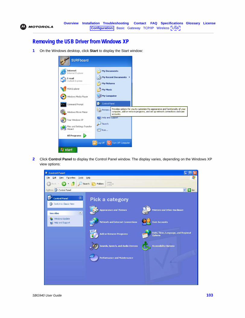
Overview Installation Troubleshooting Contact FAQ Specifications Glossary LicenseConfiguration: Basic Gateway TCP/IP Wireless USB
SBG940 User Guide 103
Removing the USB Driver from Windows XP1 On the Windows desktop, click Start to display the Start window:
2 Click Control Panel to display the Control Panel window. The display varies, depending on the Windows XP view options:
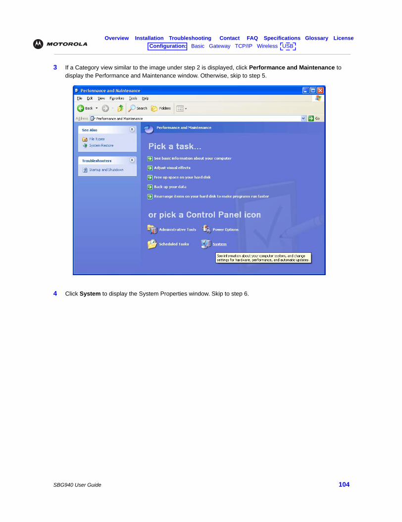
Overview Installation Troubleshooting Contact FAQ Specifications Glossary LicenseConfiguration: Basic Gateway TCP/IP Wireless USB
SBG940 User Guide 104
3 If a Category view similar to the image under step 2 is displayed, click Performance and Maintenance to display the Performance and Maintenance window. Otherwise, skip to step 5.
4 Click System to display the System Properties window. Skip to step 6.
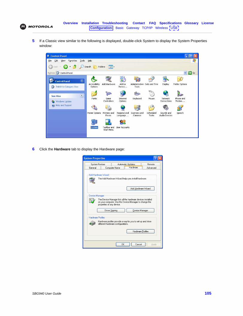
Overview Installation Troubleshooting Contact FAQ Specifications Glossary LicenseConfiguration: Basic Gateway TCP/IP Wireless USB
SBG940 User Guide 105
5 If a Classic view similar to the following is displayed, double-click System to display the System Properties window:
6 Click the Hardware tab to display the Hardware page:
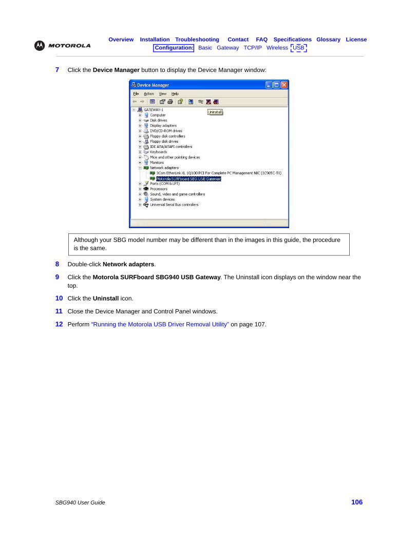
Overview Installation Troubleshooting Contact FAQ Specifications Glossary LicenseConfiguration: Basic Gateway TCP/IP Wireless USB
SBG940 User Guide 106
7 Click the Device Manager button to display the Device Manager window:
8 Double-click Network adapters.
9 Click the Motorola SURFboard SBG940 USB Gateway. The Uninstall icon displays on the window near the top.
10 Click the Uninstall icon.
11 Close the Device Manager and Control Panel windows.
12 Perform “Running the Motorola USB Driver Removal Utility” on page 107.
Although your SBG model number may be different than in the images in this guide, the procedure is the same.
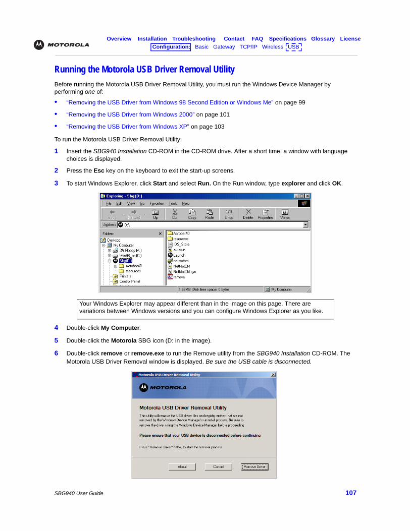
Overview Installation Troubleshooting Contact FAQ Specifications Glossary LicenseConfiguration: Basic Gateway TCP/IP Wireless USB
SBG940 User Guide 107
Running the Motorola USB Driver Removal UtilityBefore running the Motorola USB Driver Removal Utility, you must run the Windows Device Manager by performing one of:
• “Removing the USB Driver from Windows 98 Second Edition or Windows Me” on page 99
• “Removing the USB Driver from Windows 2000” on page 101
• “Removing the USB Driver from Windows XP” on page 103
To run the Motorola USB Driver Removal Utility:
1 Insert the SBG940 Installation CD-ROM in the CD-ROM drive. After a short time, a window with language choices is displayed.
2 Press the Esc key on the keyboard to exit the start-up screens.
3 To start Windows Explorer, click Start and select Run. On the Run window, type explorer and click OK.
4 Double-click My Computer.
5 Double-click the Motorola SBG icon (D: in the image).
6 Double-click remove or remove.exe to run the Remove utility from the SBG940 Installation CD-ROM. The Motorola USB Driver Removal window is displayed. Be sure the USB cable is disconnected.
Your Windows Explorer may appear different than in the image on this page. There are variations between Windows versions and you can configure Windows Explorer as you like.
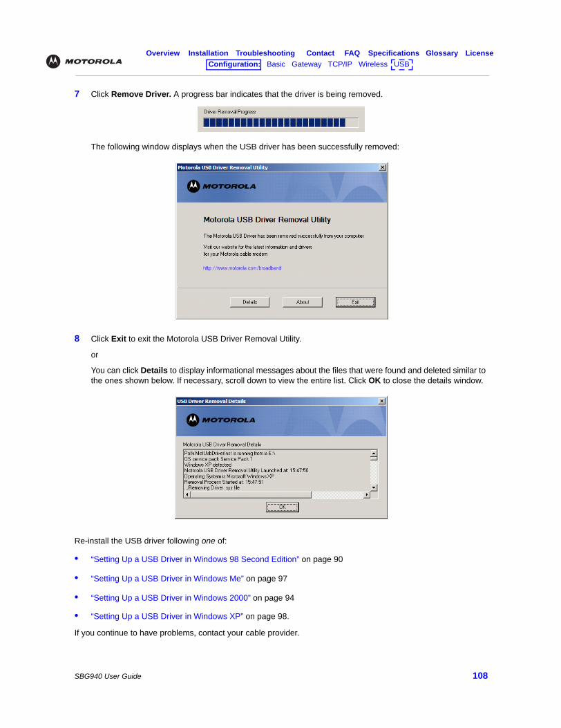
Overview Installation Troubleshooting Contact FAQ Specifications Glossary LicenseConfiguration: Basic Gateway TCP/IP Wireless USB
SBG940 User Guide 108
7 Click Remove Driver. A progress bar indicates that the driver is being removed.
The following window displays when the USB driver has been successfully removed:
8 Click Exit to exit the Motorola USB Driver Removal Utility.
or
You can click Details to display informational messages about the files that were found and deleted similar to the ones shown below. If necessary, scroll down to view the entire list. Click OK to close the details window.
Re-install the USB driver following one of:
• “Setting Up a USB Driver in Windows 98 Second Edition” on page 90
• “Setting Up a USB Driver in Windows Me” on page 97
• “Setting Up a USB Driver in Windows 2000” on page 94
• “Setting Up a USB Driver in Windows XP” on page 98.
If you continue to have problems, contact your cable provider.
Overview Installation Troubleshooting Contact FAQ Specifications Glossary LicenseConfiguration: Basic Gateway TCP/IP Wireless USB
SBG940 User Guide 109
Contact Us If you need assistance while working with the SBG940, contact your cable provider. For more information about customer service, technical support, or warranty claims, see the Regulatory, Safety, Software License, and Warranty Information card provided with the SBG940.
For answers to typical questions, see “Frequently-Asked Questions”.
For more information about Motorola consumer cable products, education, and support, visit http://broadband.motorola.com/consumers.
Overview Installation Troubleshooting Contact FAQ Specifications Glossary LicenseConfiguration: Basic Gateway TCP/IP Wireless USB
SBG940 User Guide 110
Frequently Asked QuestionsHere are answers to questions our customers frequently ask:
Q What is high-speed cable Internet access?A Cable Internet access uses cable television wires instead of telephone lines to connect to the Internet. It is
extremely fast and does not tie up telephone lines for incoming or outgoing calls and faxes.
Q How fast is the Motorola SURFboard Cable Modem Gateway SBG940?A Cable modems offer Internet access at speeds up to 100 times faster than a traditional phone modem. You
can experience speeds of over 1,000 Kbps. Network condition such as traffic volume and the speed of the sites you visit can affect download speeds.
Q How many users can one SBG940 support?A A single SBG940 can support up to 253 users, each assigned a unique IP address, on a Class C network.
Q What is Network Address Translation?A NAT is a technique to translate private IP addresses on your LAN to a single IP address assigned by your
cable provider that is visible to outside users on the Internet.
Q What are IEEE 802.11g and IEEE 802.11b?
A They are IEEE wireless network standards.
Q What type of firewall is provided on the SBG940?A The SBG940 provides a stateful-inspection firewall. For more information, see “Firewall” and “Setting the
Firewall Policy”.
Q What wireless security measures are provided on the SBG940?A To protect data transmitted over wireless connections, the SBG940 supports WPA or WEP encryption and
MAC access control lists. For information, see “Wireless Security” and “Setting Up Your Wireless LAN”.
Q Why is there no Standby button?
A As a security measure, current Motorola cable modems provide a Standby button to temporarily suspend the Internet connection. Because enabling the SBG940 firewall provides high security levels while connected, the Standby button is not required.
Q Can I still watch cable TV while using my SBG940?A Yes, your cable TV line can carry the TV signal while you send and receive information on the Internet.
Q What are CableLabs Certified, DOCSIS, and Euro-DOCSIS?
A CableLabs Certified, DOCSIS, and Euro-DOCSIS are the industry standards for high-speed data distribution over cable television system networks. They are intended to ensure that all compliant cable modems interface with all compliant cable systems. Your SBG940 is DOCSIS or Euro-DOCSIS certified.
Q If I have an SBG940, can I still use my old 28.8 Kbps or 56 Kbps modem?
A Yes you can. However, once you’ve experienced the speed of cable Internet access, you’ll never again want to wait for traditional dial-up services.
Overview Installation Troubleshooting Contact FAQ Specifications Glossary LicenseConfiguration: Basic Gateway TCP/IP Wireless USB
SBG940 User Guide 111
Q Do I need to change my Internet service provider (ISP)?
A Currently, most Internet service providers do not provide cable Internet access. Contact your cable company for your specific information.
Q Do I need to subscribe to cable TV to get cable Internet access?A No, but you will need to subscribe to cable Internet service. Some systems require that you subscribe to basic
service before you can get Internet access and/or offer a discount when you use your own SBG940. Check with your local cable company for specific information.
Q What type of technical support is available?A For questions about your Internet service, connection, or SBG940, call your cable provider.
Q What do I do if my SBG940 stops working?
A “Troubleshooting” provides tips to diagnose problems and simple solutions. If you continue to have problems, call your cable provider.
Q Can multiple game players on the SBG940 LAN log onto the same game server and play simultaneously with just one public IP address?
A It depends on the game server. For more information about gaming, see “Gaming Configuration Guidelines”.
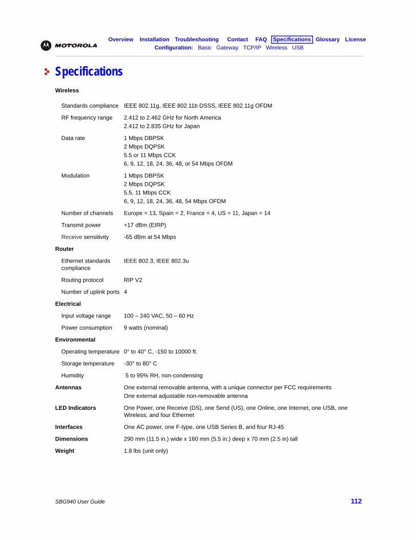
Overview Installation Troubleshooting Contact FAQ Specifications Glossary LicenseConfiguration: Basic Gateway TCP/IP Wireless USB
SBG940 User Guide 112
SpecificationsWireless
Standards compliance IEEE 802.11g, IEEE 802.11b DSSS, IEEE 802.11g OFDM
RF frequency range 2.412 to 2.462 GHz for North America2.412 to 2.835 GHz for Japan
Data rate 1 Mbps DBPSK2 Mbps DQPSK5.5 or 11 Mbps CCK6, 9, 12, 18, 24, 36, 48, or 54 Mbps OFDM
Modulation 1 Mbps DBPSK2 Mbps DQPSK5.5, 11 Mbps CCK6, 9, 12, 18, 24, 36, 48, 54 Mbps OFDM
Number of channels Europe = 13, Spain = 2, France = 4, US = 11, Japan = 14
Transmit power +17 dBm (EIRP)
Receive sensitivity -65 dBm at 54 Mbps
Router
Ethernet standards compliance
IEEE 802.3, IEEE 802.3u
Routing protocol RIP V2
Number of uplink ports 4
Electrical
Input voltage range 100 – 240 VAC, 50 – 60 Hz
Power consumption 9 watts (nominal)
Environmental
Operating temperature 0° to 40° C, -150 to 10000 ft.
Storage temperature -30° to 80° C
Humidity 5 to 95% RH, non-condensing
Antennas One external removable antenna, with a unique connector per FCC requirementsOne external adjustable non-removable antenna
LED Indicators One Power, one Receive (DS), one Send (US), one Online, one Internet, one USB, one Wireless, and four Ethernet
Interfaces One AC power, one F-type, one USB Series B, and four RJ-45
Dimensions 290 mm (11.5 in.) wide x 160 mm (5.5 in.) deep x 70 mm (2.5 in) tall
Weight 1.8 lbs (unit only)

Overview Installation Troubleshooting Contact FAQ Specifications Glossary LicenseConfiguration: Basic Gateway TCP/IP Wireless USB
SBG940 User Guide 113
Downstream
Modulation 64 or 256 QAM
Maximum data ratea 38 Mbps
Frequency range 88 to 860 MHz (30 kHz minimum step size)
Bandwidth 6 MHz
Maximum symbol rate 5.069 Msym/s (64 QAM)5.361 Msym/s (256 QAM)
Operating level range -15 to +15 dBmV
Input impedance 75 ohms (nominal)
Frequency range 88 to 860 MHz
Upstream
Modulation QPSK or 8b, 16, 32b, 64b, or 128b QAM
Modulation rate (nominal)
TDMA: 160, 320, 640, 1280, 2560, and 5120 KHzS-CDMA: 1280, 2560, and 5120 KHz
Maximum data ratec 30 Mbps
Bandwidth TDMA: 200, 400, 800, 1600, 3200, and 6400b kHzS-CDMA: 1600, 3200, and 6400 kHz
Symbol rates 160, 320, 640, 1280, and 2560 ksym/s
Operating level range (one channel)
TDMA:• +8 to +54 dBmV (32 QAM, 64 QAM)• +8 to +55 dBmV (8 QAM, 16 QAM)• +8 to +58 dBmV (QPSK)S-CDMA:• +8 to +53 dBmV (all modulations)
Output impedance 75 ohms nominal
Frequency range 5 to 42 MHz (edge to edge)
Output return loss > 6 dB (5 to 42 MHz)
General
Cable interface F-Connector, female, 75 ohm
CPE network interface USB, Ethernet 10/100Base-T (auto sensing)
CPE wireless interface IEEE 802.11g
Data protocol TCP/IP
a. Actual speed will vary. Upload and download speeds are affected by several factors including, but not limited to network traffic and services provided by your cable provider, computer equipment, server type, number of connections to the server, and the availability of Internet routers.
b. With a CMTS supporting A-TDMA or S-CDMA only.c. Actual speed will vary. Maximum speed of 30 Mbps is only attainable with A-TDMA or S-CDMA technology.
Overview Installation Troubleshooting Contact FAQ Specifications Glossary LicenseConfiguration: Basic Gateway TCP/IP Wireless USB
SBG940 User Guide 114
GlossaryThis glossary defines terms and lists acronyms used with the SBG940.
Aaccess point A device that provides WLAN connectivity to wireless clients (stations). The SBG940 acts as a
wireless access point.
adapter A device or card that connects a computer, printer, or other peripheral device to the network or to some other device. A wireless adapter connects a computer to the WLAN.
address translation
See NAT.
ALG Application level gateway triggers are required by some file transfer (for example, FTP), game, and video conferencing applications to open one or more ports to enable the application to operate properly.
American Wire Gauge (AWG)
A standard system used to designate the size of electrical conductors; gauge numbers are inverse to size.
ANSI The American National Standards Institute is a non-profit, independent organization supported by trade organizations, industry, and professional societies for standards development in the United States. This organization defined ASCII and represents the United States to the International Organization for Standardization.
ANX Automotive Network Exchange
ARP Address Resolution Protocol broadcasts a datagram to obtain a response containing a MAC address corresponding to the host IP address. When it is first connected to the network, a client sends an ARP message. The SBG940 responds with a message containing its MAC address. Subsequently, data sent by the computer uses the SBG940 MAC address as its destination.
ASCII The American Standard Code for Information Interchange refers to alphanumeric data for processing and communication compatibility among various devices; normally used for asynchronous transmission.
asynchronous timing
The SBG940 uses synchronous timing for upstream data transmissions. The CMTS broadcasts messages that bandwidth is available. The SBG940 reserves data bytes requiring x-number of mini-slots. The CMTS replies that it can receive data at a specified time (synchronized). At the specified time, the SBG940 transmits the x-number of data bytes.
attenuation The difference between transmitted and received power resulting from loss through equipment, transmission lines, or other devices; usually expressed in decibels.
authentication A process where the CMTS verifies that access is authorized, using a password, trusted IP address, or serial number.
authorization Part of the process between a CMTS and the cable modem or gateway to enable Baseline Privacy.
auto-MDIX Automatic medium-dependent interface crossover detects and corrects cabling errors by automatically reversing the send and receive pins on any port. It enables the use of straight-through wiring between the SBG940 Ethernet port and any computer, printer, or hub.
Overview Installation Troubleshooting Contact FAQ Specifications Glossary LicenseConfiguration: Basic Gateway TCP/IP Wireless USB
SBG940 User Guide 115
B
bandwidth The transmission capacity of a medium in terms of a range of frequencies. Greater bandwidth indicates the ability to transmit more data over a given period of time.
Baseline Privacy
An optional feature that encrypts data between the CMTS and the cable modem or gateway. Protection of service is provided by ensuring that a cable modem or gateway, uniquely identified by its MAC address, can only obtain keys for services it is authorized to access.
baud The analog signaling rate. For complex modulation modes, the digital bit rate is encoded in multiple bits per baud, for example, 64 QAM encodes 6 bits per baud and 16 QAM encodes 4 bits per baud.
BCP Binary Communication Protocol
BER The bit error rate is the ratio of the number of erroneous bits or characters received from some fixed number of bits transmitted.
binary A numbering system that uses two digits, 0 and 1.
bit rate The number of bits (digital 0s and 1s) transmitted per second in a communications channel. It is usually measured in bits per second bps.
BPKM Baseline Protocol Key Management encrypts data flows between a cable modem or gateway and the CMTS. The encryption occurs after the cable modem or gateway registers to ensure data privacy across the RF network.
bps bits per second
bridge An OSI layer 2 networking device that connects two LANs using similar protocols. It filters frames based on the MAC address to reduce the amount of traffic. A bridge can be placed between two groups of hosts that communicate a lot together, but not so much with the hosts in the other group. The bridge examines the destination of each packet to determine whether to transmit it to the other side. See also switch.
broadband High bandwidth network technology that multiplexes multiple, independent carriers to carry voice, video, data, and other interactive services over a single cable. A communications medium that can transmit a relatively large amount of data in a given time period. A frequently used synonym for cable TV that can describe any technology capable of delivering multiple channels and services.
broadcast Simultaneous transmission to multiple network devices; a protocol mechanism supporting group and universal addressing. See also multicast and unicast.
Overview Installation Troubleshooting Contact FAQ Specifications Glossary LicenseConfiguration: Basic Gateway TCP/IP Wireless USB
SBG940 User Guide 116
C
CableHome A project of CableLabs and technology suppliers to develop interface specifications for extending high-quality cable-based services to home network devices. It addresses issues such as device interoperability, QoS, and network management. CableHome will enable cable service providers to offer more services over HFC. It will improve consumer convenience by providing cable-delivered services throughout the home.
CableLabs A research consortium that defines the interface requirements for cable modems and acknowledges that tested equipment complies with DOCSIS.
cable modem A device installed at a subscriber location to provide data communications over an HFC network. Unless otherwise specified, all references to “cable modem” in this documentation refer to DOCSIS or Euro-DOCSIS cable modems only.
cable modem configuration file
File containing operational parameters that a cable modem or gateway downloads from the cable provider TFTP server during registration.
circuit-switched Network-connection scheme used in the traditional PSTN telephone network where each connection requires a dedicated path for its duration. An alternative is packet-switched.
Class C network An IP network containing up to 253 hosts. Class C IP addresses are in the form “network.network.network.host.”
client In a client/server architecture, a client is a computer that requests files or services such as file transfer, remote login, or printing from the server. Also called a CPE. On a WLAN, a client is any host that can communicate with the access point. A wireless client is also called a “station.”
CMTS A cable modem termination system is a device in the cable system headend that interfaces the HFC network to local or remote IP networks to connecting IP hosts, cable modems or gateways, and subscribers. It manages all cable modem bandwidth. It is sometimes called an edge router.
CNR carrier to noise ratio
coaxial cable (coax)
A type of cable consisting of a center wire surrounded by insulation and a grounded shield of braided wire. The shield minimizes electrical and radio frequency interference. Coaxial cable has high bandwidth and can support transmission over long distances.
CoS Class of service traffic management or scheduling functions are performed when transferring data upstream or downstream on HFC.
CPE Customer premise equipment, typically computers, printers, etc., are connected to the cable modem or gateway at the subscriber location. CPE can be provided by the subscriber or the cable provider. Also called a client.
crosstalk Undesired signal interfering with the desired signal.
CSMA/CD carrier sense multiple access with collision detection
Overview Installation Troubleshooting Contact FAQ Specifications Glossary LicenseConfiguration: Basic Gateway TCP/IP Wireless USB
SBG940 User Guide 117
D
datagram In RFC 1594, a datagram is defined as “a self-contained, independent entity of data carrying sufficient information to be routed from the source to the destination computer without reliance on earlier exchanges between this source and destination computer and the transporting network.” For the most part, it has been replaced by the term packet.
default route The route by which packets are forwarded when other routes in the routing table do not apply.
dB decibel
dBc Signal level expressed in dB relative to the unmodulated carrier level desired.
DBm A unit of measurement referenced to one milliwatt across specified impedance. 0dBm = 1 milliwatt across 75 ohms.
dBmV Signal level expressed in dB as the ratio of the signal power in a 75-ohm system to a reference power when 1 mV is across 75 ohms.
demodulation An operation to restore a previously modulated wave and separate the multiple signals that were combined and modulated on a subcarrier.
DHCP A Dynamic Host Configuration Protocol server dynamically assigns IP addresses to client hosts on an IP network. DHCP eliminates the need to manually assign static IP addresses by “leasing” an IP address and subnet mask to each client. It enables the automatic reuse of unused IP addresses:The SBG940 is simultaneously a DHCP client and a DHCP server. • A DHCP server at the cable system headend assigns a public IP address to the SBG940 and
optionally to clients on the SBG940 LAN.• The SBG940 contains a built-in DHCP server that assigns private IP addresses to clients.
distortion An undesired change in signal waveform within a transmission medium. A nonlinear reproduction of the input waveform.
DMZ A “de-militarized zone” is one or more hosts logically located between a private LAN and the Internet. A DMZ prevents direct access by outside users to private data. (The term comes from the geographic buffers located between some conflicting countries such as North and South Korea.) In a typical small DMZ configuration, the DMZ host receives requests from private LAN users to access external web sites and initiates sessions for these requests. The DMZ host cannot initiate a session back to the private LAN. Internet users outside the private LAN can access only the DMZ host. You can use a DMZ to set up a web server or for gaming without exposing confidential data.
DNS The Domain Name System is the Internet system for converting domain names to IP addresses. A DNS server contains a table matching domain names such as Internetname.com to IP addresses such as 192.169.9.1. When you access the world-wide web, a DNS server translates the URL displayed on the browser to the destination website IP address. The DNS lookup table is a distributed Internet database; no one DNS server lists all domain name to IP address matches.
DOCSIS The CableLabs Data-Over-Cable Service Interface Specification defines interface standards for cable modems, gateways, and supporting equipment to deliver data between an HFC network and computer systems or television sets. To emphasize its use as a cable modem standard, DOCSIS is now called CableLabs Certified Cable Modems. Euro-DOCSIS is DOCSIS adapted for use in Europe.
domain name A unique name, such as motorola.com, that maps to an IP address. Domain names are typically much easier to remember than are IP addresses.
Overview Installation Troubleshooting Contact FAQ Specifications Glossary LicenseConfiguration: Basic Gateway TCP/IP Wireless USB
SBG940 User Guide 118
E
dotted-decimal format
Method of representing an IP address or subnet mask using four decimal numbers called octets. Each octet represents eight bits. In a class C IP address, the octets are “network.network.network.host.” The first three octets together represent the network address and the final octet is the host address. In the SBG940 LAN default configuration, 192.168.100 represents the network address. In the final octet, the host address can be from 2 to 254.
download To copy a file from one computer to another. You can use the Internet to download files from a server to a computer. A DOCSIS or Euro-DOCSIS cable modem or gateway downloads its configuration file from a TFTP server during start-up.
downstream In a cable data network, the direction of data received by the computer from the Internet.
driver Software that enables a computer to interact with a network or other device. For example, there are drivers for printers, monitors, graphics adapters, modems, Ethernet, USB, HPNA, and many others.
DSL Digital Subscriber Line
DSSS Direct Sequence Spread Spectrum is an IEEE 802.11b RF modulation protocol.
dynamic IP address
An IP address that is temporarily leased to a host by a DHCP server. The opposite of static IP address.
encapsulate To include data into some other data unit to hide the format of the included data.
encode To alter an electronic signal so that only an authorized user can unscramble it to view the information.
encrypt To encode data.
endpoint A VPN endpoint terminates the VPN at the router so that computers on the SBG940 LAN do not need VPN client software to tunnel through the Internet to the VPN server.
ESSID The Extended Service Set Identifier or network name is a unique identifier that wireless clients use to associate with an access point to distinguish between multiple WLANs in the same area. All clients on a WLAN must have the same ESSID as the access point. On the SBG940, you can set the ESSID on the Wireless > NETWORK page.
Ethernet The most widely used LAN type, also known as IEEE 802.3. The most common Ethernet networks are 10Base-T, which provide transmission speeds up to 10 Mbps, usually over unshielded, twisted-pair wire terminated with RJ-45 connectors. Fast Ethernet (100Base-T) provides speeds up to 100 Mbps. “Base” means “baseband technology” and “T” means “twisted pair cable.”’Each Ethernet port has a physical address called the MAC address.
Euro-DOCSIS A tComLabs standard that is DOCSIS adapted for use in Europe.
event A message generated by a device to inform an operator or the network management system that something has occurred.
expansion slot A connection point in a computer where a circuit board can be inserted to add new capabilities.
EAP Extensible Authentication Protocol
Overview Installation Troubleshooting Contact FAQ Specifications Glossary LicenseConfiguration: Basic Gateway TCP/IP Wireless USB
SBG940 User Guide 119
F
G
FCS frame check sequence
F-type connector
A type of connector used to connect coaxial cable to equipment such as the SBG940.
firewall A security software system on the SBG940 that enforces an access control policy between the Internet and the SBG940 LAN.
flow A data path moving in one direction.
FEC Forward error correction is a technique to correct transmission errors without requiring the transmitter to resend any data.
FDMA Frequency Division Multiple Access is a method to allow multiple users to share a specific radio spectrum. Each active user is assigned an individual RF channel (or carrier) with the carrier frequency of each channel offset from its adjacent channels by an amount equal to the channel spacing, which allows the required bandwidth per channel.
frame A unit of data transmitted between network nodes that contains addressing and protocol control data. Some control frames contain no data.
frequency Number of times an electromagnetic signal repeats an identical cycle in a unit of time, usually one second, measured in Hz, kHz, MHz, or GHz.
FTP File Transfer Protocol is a standard Internet protocol for exchanging files between computers. FTP is commonly used to download programs and other files to a computer from web pages on Internet servers.
full-duplex The ability to simultaneously transmit and receive data. See also half-duplex.
gain The extent to which a signal is boosted. A high gain antenna increases the wireless signal level to increase the distance the signal can travel and remain usable.
gateway A device that enables communication between networks using different protocols. See also router.The SBG940 enables up to 253 computers supporting IEEE 802.11b, Ethernet, or USB to share a single broadband Internet connection.
gateway IP address
The address of the default gateway router on the Internet. Also known as the “giaddr.”
GHz Gigahertz — one billion cycles per second.
GUI graphical user interface
Overview Installation Troubleshooting Contact FAQ Specifications Glossary LicenseConfiguration: Basic Gateway TCP/IP Wireless USB
SBG940 User Guide 120
H
H.323 A suite of protocols created by the ITU for interactive video-conferencing, data sharing, and audio applications such as VoIP.
half-duplex Network where only one device at a time can transmit data. See also full-duplex.
headend A location that receives TV programming, radio programming, data, and telephone calls that it modulates onto the HFC network. It also sends return data and telephone transmissions. Headend equipment includes transmitters, preamplifiers, frequency terminals, demodulators, modulators, and other devices that amplify, filter, and convert incoming broadcast TV signals to wireless and cable channels.
header The data at the beginning of a packet that identifies what is in the packet.
hexadecimal A base-sixteen numbering system that uses sixteen sequential numbers (0 to 9 and the letters A to F) as base units before adding a new position. On computers, hexadecimal is a convenient way to express binary numbers.
HFC A hybrid fiber/coaxial cable network uses fiber-optic cable as the trunk and coaxial cable to the subscriber premises.
hop The interval between two routers on an IP network. The number of hops a packet traverses toward its destination (called the hop count) is saved in the packet header. For example, a hop count of six means the packet has traversed six routers. The packet hop count increases as the time-to-live (TTL) value decreases.
host In IP, a host is any computer supporting end-user applications or services with full two-way network access. Each host has a unique host number that combined with the network number forms its IP address. Host also can mean:• A computer running a web server that serves pages for one or more web sites belonging to
organization(s) or individuals• A company that provides this service• In IBM environments, a mainframe computer
HTML Hyper Text Markup Language
hub On a LAN, a hub is a device that connects multiple hosts to the LAN. A hub performs no data filtering. See also bridge and router. An IP hub is typically a unit on a rack or desktop.On an HFC network, a hub is a scaled-down headend that performs some or all headend functions for part of the system.
Hz Hertz — one cycle per second. The unit to measure the frequency that an alternating electromagnetic signal cycles through its highest and lowest states. Used to define the bands of the electromagnetic spectrum used in voice and data communications, or to define the bandwidth of a transmission medium.
Overview Installation Troubleshooting Contact FAQ Specifications Glossary LicenseConfiguration: Basic Gateway TCP/IP Wireless USB
SBG940 User Guide 121
I IANA The Internet Numbering Address Authority (IANA) is an organization under the Internet Architecture
Board (IAB) of the Internet Society that oversees IP address allocation. It is under a contract from the U.S. government.
ICMP Internet Control Message Protocol is a protocol used for error, problem, and informational messages sent between IP hosts and gateways. ICMP messages are processed by the IP software and are not usually apparent to the end-user.
ICSA The International Computer Security Association is the security industry’s main source of research, intelligence, and product certification.
IEEE The Institute of Electrical and Electronics Engineers, Inc. (http://www.ieee.org) is an organization that produces standards, technical papers, and symposiums for the electrical and electronic industries and is accredited by ANSI.
IEEE 802.11b IEEE 802.11g
IEEE wireless network standards.
IEEE 802.3 See Ethernet.
IETF The Internet Engineering Task Force (http://www.ietf.org) is an open international community of network designers, operators, vendors, and researchers to develop and maintain Internet architecture. Technical working groups issue working documents called Internet-Drafts. The IETF publishes review versions of the drafts called requests for comments (RFCs).
IGMP Internet Group Membership Protocol is the Internet multicasting standard. IGMP establishes and maintains a database of group multicast addresses and interfaces to which a multicast router forwards multicast packets. IGMP runs between multicast hosts and their immediately-neighboring multicast routers.
IGMP spoofing A process where a router acts as an IGMP querier for multicast hosts and an IGMP host to a multicast router.
impedance The total opposition to AC electron current flow within a device. Impedance is typically 75 ohms for coax cable and other CATV components.
impulse noise Noise of very short in duration, typically of the order of 10 microseconds. It is caused by electrical transients such as voltage spikes, electric motors turning on, and lightning or switching equipment that bleed over to the cable.
ingress noise Noise typically caused by discrete frequencies picked up by the cable plant from radio broadcasts or an improperly grounded or shielded home appliance such as a hair dryer. Ingress is the major source of cable system noise.
Internet A worldwide collection of interconnected networks using TCP/IP.
Internetwork A collection of interconnected networks allowing communication between all devices connected to any network in the collection.
IP Internet Protocol is a set of standards that enable different types of computers to communicate with one another and exchange data through the Internet. IP provides the appearance of a single, seamless communication system and makes the Internet a virtual network.
Overview Installation Troubleshooting Contact FAQ Specifications Glossary LicenseConfiguration: Basic Gateway TCP/IP Wireless USB
SBG940 User Guide 122
K
IP address A unique 32-bit value that identifies each host on a TCP/IP network. TCP/IP networks route messages based on the destination IP address. An IP address has two parts: • The network address is assigned by IANA.• The SBG940 network administrator assigns a host address to each host connected to the SBG940,
automatically using its DHCP server or as a static IP address.For a Class C network, the first 24 bits are the network address and the final 8 bits are the host address; in dotted-decimal format it appears “network.network.network.host.”If you enable the SBG940 DHCP client on the WAN page, the cable provider automatically assigns the network address, subnet mask, domain name, and DNS server to provide a continuous Internet connection.
IPSec The Internet Protocol Security protocols are IETF authentication and encryption standards for secure packet exchange over the Internet. IPSec works at OSI layer 3 and secures everything on the network.
IKE Internet Key Exchange
ISAKMP Internet Security Association and Key Management Protocol
ISDN Integrated Services Digital Network
ISO The International Organization for Standardization (http://www.iso.ch) is a worldwide federation of national standards bodies from approximately 140 countries. ISO is a non-governmental organization established in 1947 to promote the development of standardization and related activities in the world with a view to facilitating the international exchange of goods and services, and to developing cooperation in the spheres of intellectual, scientific, technological, and economic activity.
ISP Internet Service Provider
ITU International Telecommunications Union
kHz kilohertz — one thousand cycles per second
Overview Installation Troubleshooting Contact FAQ Specifications Glossary LicenseConfiguration: Basic Gateway TCP/IP Wireless USB
SBG940 User Guide 123
L
L2F Layer 2 Forwarding is an OSI layer 2 protocol that establishes a secure tunnel across the Internet to create a virtual PPP connection between the user and the enterprise network. L2F is the most established and stable layer 2 tunneling protocol.
L2TP Layer 2 Tunnel Protocol is a PPP extension that enables ISPs to operate VPNs. L2TP merges the best features of the PPTP and L2F. L2TP is the emerging IETF standard.
LAC An L2TP access concentrator is a device to which the client directly connects through which PPP frames are tunneled to the LNS. The LAC need only implement the media over which L2TP operates to transmit traffic to one or more LNSs. The LAC may tunnel any protocol carried within PPP. The LAC initiates incoming calls and receives outgoing calls. A LAC is analogous to an L2F NAS.
LAN A local area network provides a full-time, high-bandwidth connection over a limited area, such as a building or campus. Ethernet is the most widely used LAN standard.
layer In networks, layers are software protocol levels. Each layer performs functions for the layers above it. OSI is a reference model having seven functional layers.
LCP Link Control Protocol establishes, configures, and tests data link connections used by PPP.
latency The time required for a signal to pass through a device. It is often expressed in a quantity of symbols.
LED light-emitting diode
LNS An L2TP network server is a termination point for L2TP tunnels where PPP frames are processed and passed to higher layer protocols. An LNS can operate on any platform that terminates PPP. The LNS handles the server side of the L2TP protocol. L2TP relies only on the single media over which L2TP tunnels arrive. The LNS can have a single LAN or WAN interface but can terminate calls arriving at any of the LACs full range of PPP interfaces (asynchronous, synchronous, ISDN, V.120, etc.). The LNS initiates outgoing calls and receives incoming calls. An LNS is analogous to a home gateway in L2F technology.
loopback A test that loops the transmit signal to the receive signal. Usually the loopback test is initiated on a network device. The test is used to verify a path or to measure the quality of a signal on that path.
Overview Installation Troubleshooting Contact FAQ Specifications Glossary LicenseConfiguration: Basic Gateway TCP/IP Wireless USB
SBG940 User Guide 124
M
MAC address The Media Access Control address is a unique, 48-bit value permanently saved in ROM at the factory to identify each Ethernet network device. It is expressed as a sequence of 12 hexadecimal digits printed on a Label on the Bottom of the SBG940. You need to provide the HFC MAC address to the cable provider. Also called an Ethernet address, physical address, hardware address, or NIC address.
MB One megabyte; equals 1,024 x 1,024 bytes, 1,024 kilobytes, or about 8 million bits.
Mbps Million bits per second (megabits per second). A rate of data transfer.
media The various physical environments through which signals pass; for example, coaxial, unshielded twisted-pair (UTP), or fiber-optic cable.
MIB A management information base is a unique hierarchical structure of software objects used by the SNMP manager and agent to configure, monitor, or test a device.
MHz Megahertz — one million cycles per second. A measure of radio frequency.
MPDU MAC protocol data unit (PDU)
MSDU MAC service data unit
MSO Multiple Systems Operator. A company that owns and operates more than one cable system. Also called a group operator.
MTU The Maximum Transmission Unit is the largest amount of data that can be transmitted in one discrete message on a given physical network. The MTU places an upper bound on the size of a message that can be transferred by the network in a single frame. Messages exceeding the MTU must be fragmented before transmission, and reassembled at the destination.
multicast A data transmission sent from one sender to multiple receivers. See also broadcast and unicast.
mW milliwatts
Overview Installation Troubleshooting Contact FAQ Specifications Glossary LicenseConfiguration: Basic Gateway TCP/IP Wireless USB
SBG940 User Guide 125
N
O
NAS network access server
NAT Network Address Translation is an Internet standard for a LAN to use one set of IP addresses for internal traffic and a second set of IP addresses for external traffic. NAT provides some security because the IP addresses of SBG940 LAN computers are invisible on the Internet.If NAT is enabled on the Gateway page, there is a one-to-one mapping between each public IP address and client IP address.
NAPT Network Address Port Translation is the most common form of address translation between public and private IP addresses. NAPT is a mapping of one public IP address to many private IP addresses. If NAPT is enabled on the Gateway page, one public IP address is mapped to an individual private IP address for up to 245 LAN clients.
NEC National Electrical Code (United States) — The regulations for construction and installation of electrical wiring and apparatus, suitable for mandatory application by a wide range of state and local authorities.
network Two or more computers connected to communicate with each other. Networks have traditionally been connected using some kind of wiring.
network driver Software packaged with a NIC that enables the computer to communicate with the NIC.
network layer Layer 3 in the OSI architecture that provides services to establish a path between open systems. The network layer knows the address of the neighboring nodes, packages output with the correct network address data, selects routes, and recognizes and forwards to the transport layer incoming messages for local host domains.
NIC A network interface card converts computer data to serial data in a packet format that it sends over the LAN. A NIC is installed in an expansion slot or can be built-in. Every Ethernet NIC has a MAC address permanently saved in its ROM.
node On a LAN, a generic term for any network device.On an HFC network, the interface between the fiber-optic trunk and coaxial cable feeders to subscriber locations. A node is typically located in the subscriber neighborhood.
noise Random spurts of electrical energy or interface. May produce a salt-and-pepper pattern on a television picture.
ohm A unit of electrical resistance.
OSI The Open Systems Interconnection reference model is an illustrative model describing how data moves from an application on the source host through a network to an application on the destination host. It is a conceptual framework developed by ISO that is now the primary model for intercomputer communications. OSI is a model only; it does not define a specific networking interface.
Overview Installation Troubleshooting Contact FAQ Specifications Glossary LicenseConfiguration: Basic Gateway TCP/IP Wireless USB
SBG940 User Guide 126
P
packet The unit of data that is routed between the sender and destination on the Internet or other packet-switched network. When data such as an e-mail message or other file is sent over the Internet, IP on the sender divides the data into uniquely-numbered packets. The packet header contains the source and destination IP addresses. The individual packets may travel different routes. When all packets arrive at the destination, IP at that end reassembles the packets. The header and the data can vary in length. Packet and datagram are similar in meaning.
packet- switched
A scheme to handle transmissions on a connectionless network such as the Internet. An alternative is circuit-switched.
PacketCable A CableLabs-led project to define a common platform to deliver advanced real-time multimedia services over two-way HFC cable plant. Built on DOCSIS 1.1, PacketCable networks use IP technology as the basis for a highly-capable multimedia architecture.
pass-through A pass-through client on the SBG940 LAN obtains its public IP address from the cable provider DHCP server.
PAT Port Address Translation
PCI Peripheral Component Interconnect
PCMCIA The Personal Computer Memory Card International Association sets international standards for connecting peripherals to portable computers. Laptop computers typically have a PCMCIA slot that can hold one or two PC Cards to provide features such as Ethernet connectivity.
PDA personal digital assistant
PDU A protocol data unit is a message containing operational instructions used for SNMP. The basic SNMP V2 PDU types are get-request, get-next-request, get-bulk-request, response, set-request, inform-request, and trap.
periodic ranging
Ranging that is performed on an on-going basis after initial ranging has taken place.
physical layer Layer 1 in the OSI architecture. It provides services to transmit bits or groups of bits over a transmission link between open systems. It entails the electrical, mechanical, and handshaking procedures.
piggybacking A process that occurs when a cable modem simultaneously transmits data and requests additional bandwidth.
PING A network utility that tests host reachability by sending a small packet to the host and waiting for a reply. If you PING a computer IP address and receive a reply, you know the computer is reachable over the network. It also stands for “Packet InterNet Groper.”
PMD The physical media-dependent sublayer of the physical layer which transmits bits or groups of bits over particular types of transmission links between open systems. It entails the electrical, mechanical, and handshaking procedures.
point-to-point Physical connection made from one point to another.
POTS The “plain old telephone service” offered through the PSTN; basic analog telephone service. POTS uses the lowest 4 kHz of bandwidth on twisted pair wiring.
port On a computer or other electronic device, a port is a socket or plug used to physically connect it to the network or to other devices.in TCP/IP, a port is a number from 0 to 65536 used logically by a client program to specify a server program. Ports 0 to 1024 are reserved
Overview Installation Troubleshooting Contact FAQ Specifications Glossary LicenseConfiguration: Basic Gateway TCP/IP Wireless USB
SBG940 User Guide 127
Q
port mirroring A feature that enables one port (source) on the SBG940 to be copied to another port (destination) to be studied. The destination mirrors the transmitted (from) or received (to) data on the source port to enable the person managing the network to monitor activity.
port triggering A mechanism that allows incoming communication with specified applications. Primarily used for gaming applications.
PPP Point-to-Point Protocol is used to transport other protocols, typically for simple links over serial lines. It is most commonly used to access the Internet with a dial-up modem.
PPTP Point-to-Point Tunneling Protocol encapsulates other protocols. It is a new technology to create VPNs developed jointly by several vendors.
private IP address
An IP address assigned to a computer on the SBG940 LAN by the DHCP server on the SBG940 for a specified lease time. Private IP addresses are used by the SBG940 LAN only; they are invisible to devices on the Internet. See also public IP address.
protocol A formal set of rules and conventions for exchanging data. Different computer types (for example PC, UNIX, or mainframe) can communicate if they support common protocols.
provisioning The process of autodiscovery or manually configuring a cable modem on the CMTS.
PSTN The public switched telephone network is the traditional circuit-switched, voice-oriented telephone network. See also POTS.
public IP address
The IP address assigned to the SBG940 by the cable provider. A public IP address is visible to devices on the Internet. See also private IP address.
QAM Quadrature Amplitude Modulation uses amplitude and phase modulation to encode multiple bits of data in one signaling element. QAM achieves faster data transfer than amplitude or phase modulation alone, but the signal is more prone to errors caused by noise. QAM requires a transmission circuit with a higher CNR than alternate modulation formats such as QPSK. Two types of QAM are:• 16 QAM encodes four bits per symbol as one of 16 possible amplitude and phase combinations. • 64 QAM encodes six bits per symbol as one of 64 possible amplitude and phase combinations.
QPSK Quadrature Phase Shift Key (QPSK) modulation sends two bits of information per symbol period with one symbol 90 degrees out of phase with other symbols. The four constellation points represented by the coordinates (0,0 – 0,1 – 1,0 – 1,1) represent the four possible combinations.
QoS Quality of service describes the priority, delay, throughput, and bandwidth of a connection.
Overview Installation Troubleshooting Contact FAQ Specifications Glossary LicenseConfiguration: Basic Gateway TCP/IP Wireless USB
SBG940 User Guide 128
R
RAS Remote Access Server
registration How a cable modem makes itself known to the CMTS. The cable modem configuration file and authorization are verified and the CoS is negotiated.
return loss A measurement of the quality of the match of the device to the cable system. Return loss is the ratio of the amount of power reflected by the device. A return loss of 20 dB or greater is preferred.
RF Radio Frequency — signals used by the CMTS transmitter and receiver to send data over HFC. The carrier is modulated to encode the digital data stream for transmission across the cable network.
RFC Request for Comments published on the IETF or other websites. Many RFCs become international standards.
RJ-11 The most common type of connector for household or office phones.
RJ-45 An 8-pin modular connector; the most common connector type for 10Base-T or 100Base-T Ethernet networks.
ROM read-only memory
router On IP networks, a device connecting at least two networks, which may or may not be similar. A router is typically located at a gateway between networks. A router operates on OSI network layer 3. It filters packets based on the IP address, examining the source and destination IP addresses to determine the best route on which to forward them. A router is often included as part of a network switch. A router can also be implemented as software on a computer.
routing table A table listing available routes that is used by a router to determine the best route for a packet.
RTS request to send
Overview Installation Troubleshooting Contact FAQ Specifications Glossary LicenseConfiguration: Basic Gateway TCP/IP Wireless USB
SBG940 User Guide 129
S
server In a client/server architecture, a dedicated computer that supplies files or services such as file transfer, remote login, or printing to clients.
scope The set of IP addresses that a DHCP server can lease to clients.
service provider A company providing cable data services to subscribers.
SID A service ID is a unique 14-bit identifier the CMTS assigns to a cable modem or gateway that identifies the traffic type it carries (for example, data or voice). The SID provides the basis for the CMTS to allocate bandwidth to the cable modem and implement CoS.
SDU service data unit
SME small and medium enterprise
SMTP Simple Mail Transfer Protocol is a standard Internet protocol for transferring e-mail.
SNMP Simple Network Management Protocol is a standard to monitor and manage networks and network devices. Data is exchanged using PDU messages.
SOHO small office home office
spectrum A specified range of frequencies used for transmission of electromagnetic signals.
spectrum allocation
An allocation of portions of the available electromagnetic spectrum for specific services, such as AM, FM, or personal communications.
splitter A device that divides the signal from an input cable between two or more cables.
stateful inspection
A type of firewall that tracks each connection traversing all firewall interfaces to ensure validity. In addition to examining the source and destination in the packet header based on static rules, a stateful inspection firewall:• Examines packet headers on context established by previous packets that traversed the firewall• Monitors the connection state and saves it in a table• Closes ports until a connection to a specific port is requested• May examine the packet contents up through the application layer to determine more than just the
source and destinationA stateful-inspection firewall is more advanced than a static filter firewall.
static filter A type of firewall that examines the source and destination in the packet header based on administrator-defined rules only.
static IP address
An IP address that is permanently assigned to a host. Normally, a static IP address must be assigned manually. The opposite of dynamic IP address.
static route A manually-defined route.
station IEEE 802.11b term for wireless client.
subscriber A home or office user who accesses television, data, or other services from a cable provider.
subnet mask A bit mask that is logically ANDed with the destination IP address of a packet to determine the network address. A router routes packets using the network address.
subnetwork A part of a network; commonly abbreviated “subnet.” When subnetting is used, the host portion of the IP address is divided into a subnet and host number. Hosts and routers use the subnet mask to identify the bits used for the network and subnet number.
Overview Installation Troubleshooting Contact FAQ Specifications Glossary LicenseConfiguration: Basic Gateway TCP/IP Wireless USB
SBG940 User Guide 130
T
switch On an Ethernet network, a switch filters frames based on the MAC address, in a manner similar to a bridge. A switch is more advanced because it can connect more than two segments.
symbol rate Also known as baud rate, is a measure of the number of times per second a signal in a communications channel varies, or makes a transition between states (states being frequencies, voltage levels or phase angles). Usually measured in symbols per second (sps).
SYSLOG A de-facto UNIX standard for logging system events.
TBCP Tagged Binary Communication Protocol
TCP Transmission Control Protocol on OSI transport layer four, provides reliable transport over the network for data transmitted using IP (network layer three). It is an end-to-end protocol defining rules and procedures for data exchange between hosts on top of connectionless IP. TCP uses a timer to track outstanding packets, checks error in incoming packets, and retransmits packets if requested.
TCP/IP The Transmission Control Protocol/Internet Protocol suite provides standards and rules for data communication between networks on the Internet. It is the worldwide internetworking standard and the basic communications protocol of the Internet.
TFTP Trivial File Transfer Protocol is a very simple protocol used to transfer files.
TKIP Temporal Key Integrity Protocol
transparent bridging
A method to enable all hosts on the wired Ethernet LAN, WLAN, and USB connection to communicate as if they were all connected to the same physical network.
transport layer Layer of the OSI concerned with protocols for error recognition and recovery. This layer also regulates information flow.
trunk Electronic path over which data is transmitted.
TTL The time to live is the number of routers (or hops) a packet can traverse before being discarded. When a router processes a packet, it decreases the TTL by 1. When the TTL reaches zero, the packet is discarded.
tunnel To place packets inside other packets to send over a network. The protocol of the enclosing packet is understood by each endpoint, or tunnel interface, where the packet enters and exits the network. VPNs rely on tunneling to create a secure network.Tunneling requires the following protocol types: • A carrier protocol, such as TCP, used by the network that the data travels over • An encapsulating protocol, such as IPSec, L2F, L2TP, or PPTP, that is wrapped around the original
data • A passenger protocol, such as IP, for the original data
two-way A cable system that can transmit signals in both directions to and from the headend and the subscriber.
Overview Installation Troubleshooting Contact FAQ Specifications Glossary LicenseConfiguration: Basic Gateway TCP/IP Wireless USB
SBG940 User Guide 131
U-Z
UDP User Datagram Protocol
unicast A point-to-point data transmission sent from one sender to one receiver. This is the normal way you access websites. See also broadcast and multicast.
upstream In a cable data network, upstream describes the direction of data sent from the subscriber computer through the cable modem to the CMTS and the Internet.
USB Universal Serial Bus is a computer interface for add-on devices such as printers, scanners, mice, modems, or keyboards. USB supports data transfer rates of 12 Mbps and plug-and-play installation. You can connect up to 127 devices to a single USB port.
UTP unshielded twisted pair (wire)
VLAN A virtual local area network is group of devices on different LAN segments that are logically configured to communicate as if they are connected to the same wire.
VoIP Voice over Internet Protocol is a method to exchange voice, fax, and other information over the Internet. Voice and fax have traditionally been carried over traditional telephone lines of the PSTN using a dedicated circuit for each line. VoIP enables calls to travel as discrete data packets on shared lines. VoIP is an important part of the convergence of computers, telephones, and television into a single integrated information network.
VPN A virtual private network is a private network that uses “virtual” connections (tunnels) routed over a public network (usually the Internet) to provide a secure and fast connection; usually to users working remotely at home or in small branch offices. A VPN connection provides security and performance similar to a dedicated link (for example, a leased line), but at much lower cost.
WAN A wide-area network provides a connection over a large geographic area, such as a country or the whole world. The bandwidth depends on need and cost, but is usually much lower than for a LAN.
WAP Wireless access point or Wireless Access Protocol. See also access point.
WECA The Wireless Ethernet Compatibility Alliance is a trade organization that works to ensure that all wireless devices — computer cards, laptops, air routers, PDAs, etc — can communicate with each other.
WEP Wired Equivalent Privacy encryption protects the privacy of data transmitted over a WLAN. WEP uses keys to encrypt and decrypt transmitted data. The access point must authenticate a client before it can transfer data to another client. WEP is part of IEEE 802.11b. Because WEP can be difficult to use and does not provide very strong encryption, we recommend using WPA if possible.
WiFi Wireless fidelity (pronounced y-phi) brand name applied to products supporting IEEE 802.11b.
Wireless Cable Modem Gateway
The Motorola SURFboard Wireless Cable Modem Gateway is a single device that combines a cable modem, router, Ethernet switch, wireless access point, and DHCP server for SOHO or SME use.
WLAN wireless LAN
world wide web An interface to the Internet that you use to navigate and hyperlink to information.
WPA Wi-Fi Protected Access (WPA) encryption, as described on the Wi-Fi Alliance Wi-Fi Protected Access web page http://www.wifialliance.org/OpenSection/protected_access.asp). It is a far more robust form of encryption than WEP. We recommend using WPA if all of your client hardware supports WPA.
Overview Installation Troubleshooting Contact FAQ Specifications Glossary LicenseConfiguration: Basic Gateway TCP/IP Wireless USB
SBG940 User Guide 132
Software License Motorola, Inc., Connected Home Solutions (“Motorola”), 101 Tournament Drive, Horsham, PA 19044IMPORTANT: PLEASE READ THIS SOFTWARE LICENSE (“LICENSE”) CAREFULLY BEFORE YOU INSTALL, DOWNLOAD OR USE ANY APPLICATION SOFTWARE, USB DRIVER SOFTWARE, FIRMWARE AND RELATED DOCUMENTATION (“SOFTWARE”) PROVIDED WITH MOTOROLA’S CABLE DATA PRODUCT (THE “CABLE DATA PRODUCT”). BY USING THE CABLE DATA PRODUCT AND/OR INSTALLING, DOWNLOADING OR USING ANY OF THE SOFTWARE, YOU INDICATE YOUR ACCEPTANCE OF EACH OF THE TERMS OF THIS LICENSE. UPON ACCEPTANCE, THIS LICENSE WILL BE A LEGALLY BINDING AGREEMENT BETWEEN YOU AND MOTOROLA. THE TERMS OF THIS LICENSE APPLY TO YOU AND TO ANY SUBSEQUENT USER OF THIS SOFTWARE. IF YOU DO NOT AGREE TO ALL OF THE TERMS OF THIS LICENSE (I) DO NOT INSTALL OR USE THE SOFTWARE AND (II) RETURN THE CABLE DATA PRODUCT AND THE SOFTWARE (COLLECTIVELY, “PRODUCT”), INCLUDING ALL COMPONENTS, DOCUMENTATION AND ANY OTHER MATERIALS PROVIDED WITH THE PRODUCT, TO YOUR POINT OF PURCHASE OR SERVICE PROVIDER, AS THE CASE MAY BE, FOR A FULL REFUND.The Software includes associated media, any printed materials, and any “on-line” or electronic documentation, as well as any updates, revisions, bug fixes, or drives obtained by you from Motorola or your service provider. Software provided by third parties may be subject to separate end-user license agreements from the manufacturers of such Software.The Software is never sold. Motorola licenses the Software to the original customer and to any subsequent licensee for personal use only on the terms of this License. Motorola and its 3rd party licensors retain the ownership of the Software. You may:USE the Software only in connection with the operation of the Product. TRANSFER the Software (including all component parts and printed materials) permanently to another person, but only if the person agrees to accept all of the terms of this License. If you transfer the Software, you must at the same time transfer the Product and all copies of the Software (if applicable) to the same person or destroy any copies not transferred. TERMINATE this License by destroying the original and all copies of the Software (if applicable) in whatever form.You may not:(1) Loan, distribute, rent, lease, give, sublicense or otherwise transfer the Software, in whole or in part, to any other person, except as permitted under the TRANSFER paragraph above. (2) Copy or translate the User Guide included with the Software, other than for personal use. (3) Copy, alter, translate, decompile, disassemble or reverse engineer the Software, including but not limited to, modifying the Software to make it operate on non-compatible hardware. (4) Remove, alter or cause not to be displayed, any copyright notices or startup message contained in the Software programs or documentation. (5) Export the Software or the Product components in violation of any United States export laws.The Product is not designed or intended for use in on-line control of aircraft, air traffic, aircraft navigation or aircraft communications; or in design, construction, operation or maintenance of any nuclear facility. MOTOROLA AND ITS 3RD PARTY LICENSORS DISCLAIM ANY EXPRESS OR IMPLIED WARRANTY OF FITNESS FOR SUCH USES. YOU REPRESENT AND WARRANT THAT YOU SHALL NOT USE THE PRODUCT FOR SUCH PURPOSES.Title to this Software, including the ownership of all copyrights, mask work rights, patents, trademarks and all other intellectual property rights subsisting in the foregoing, and all adaptations to and modifications of the foregoing shall at all times remain with Motorola and its 3rd party licensors. Motorola retains all rights not expressly licensed under this License. The Software, including any images, graphics, photographs, animation, video, audio, music and text incorporated therein is owned by Motorola or its 3rd party licensors and is protected by United States copyright laws and international treaty provisions. Except as otherwise expressly provided in this License, the copying, reproduction, distribution or preparation of derivative works of the Software, any portion of the Product or the documentation is strictly prohibited by such laws and treaty provisions. Nothing in this License constitutes a waiver of Motorola’s rights under United States copyright law.This License and your rights regarding any matter it addresses are governed by the laws of the Commonwealth of Pennsylvania, without reference to conflict of laws principles. THIS LICENSE SHALL TERMINATE AUTOMATICALLY if you fail to comply with the terms of this License.Motorola is not responsible for any third party software provided as a bundled application, or otherwise, with the Software.U.S. GOVERNMENT RESTRICTED RIGHTSThe Product and documentation is provided with RESTRICTED RIGHTS. The use, duplication or disclosure by the Government is subject to restrictions as set forth in subdivision (c)(1)(ii) of The Rights in Technical Data and Computer Software clause at 52.227-7013. The contractor/manufacturer is Motorola, Inc., Connected Home Solutions, 101 Tournament Drive, Horsham, PA 19044.