Embed Size (px)
Citation preview
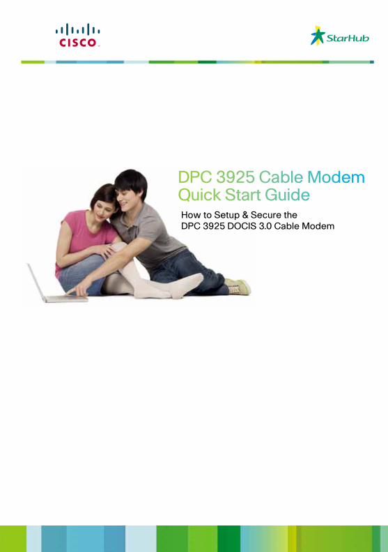
DPC 3925 Cable ModemQuick Start GuideHow to Setup & Secure the DPC 3925 DOCIS 3.0 Cable Modem
Table of Contents1. Introduction .................................................................................................................................................... 3
2. Benefits & Features ................................................................................................................................. 4
3. Before You Begin ...................................................................................................................................... 5
4. What’s in the Carton? ............................................................................................................................. 5
5. Front Panel Description ...................................................................................................................... 6
6. Back Panel Description......................................................................................................................... 7
7. How to Setup and Secure the DPC 3925 DOCSIS 3.0 Cable Modem ....... 8
8. Tips for Improved Performance .................................................................................................... 11
Welcome to the exciting world of high-speed Internet and high-quality digital telephone service. Your new Cisco® Model DPC3925 DOCSIS® 3.0 Wireless Residential Gateway with Embedded Digital Voice Adapter is a cable modem that meets industry standards for high-speed data connectivity along with reliable digital telephone service. The DPC3925 residential gateway delivers data, voice and wired (Ethernet) or wireless gateway capabilities to support high-speed data access and cost-effective voice services, all in one single device.
Designed for the active digital home or office, the DPC3925 integrated router features a Dynamic Host Configuration Protocol (DHCP) server. Network Address and Port Translation (NAT/NAPT) and a Stateful Packet Inspection (SPI) firewall. These features allow the user to share a single high-speed public Internet connection as well as share files and folders between devices within the home network by attaching multiple wired and wireless devices in the user’s home or office to the wireless residential gateway. Consumer-friendly features like Wireless Protected Setup (WPS) and user-configured Parental Control can protect the home network from unwelcome intruders and family members from access to undesirable websites.
This Quick Start Guide provides procedures and recommendations for placing, installing, configuring, operating, and troubleshooting your DPC3925 residential gateway for high-speed Internet and digital telephone service for your home or office. Refer to the appropriate section in this guide for the specific information you need for your situation. Contact your service provider for more information about subscribing to these services.
Introduction
DOCSIS• Compliant with DOCSIS 3.0, 2.0, 1.1, and 1.0 standards along with PacketCableTM 1.5, 1.0 specifications to deliver high-end performance and reliability
Connections• 1000/100/10BASE-T Ethernet ports to provide wired connectivity• High performance broadband Internet connectivity to energize your online experience• 2.4 GHz 802.11n Wireless Access Point (WAP)• WPS, including a push-button switch to activate WPS for simplified and secure wireless setup• Two-line or single-line RJ-11 telephony ports for connecting to in- home wiring or directly to conventional telephones or fax machines
Design and Function• Quick Links for making home network changes• Dual colour LEDs provide a user-friendly method to check real- time operational status• Attractive, compact design and versatile orientation to stand vertically, lie flat on the desktop or shelf, or mount easily on a wall• TR-068 compliant colour-coded interface ports and corresponding cables simplify installation and setup
Management• User-configurable Parental Control blocks access to undesirable internet sites• Advanced firewall technology deters hackers and protects the home network from unauthorized access• Allows automatic software upgrades by your service provider
Benefits and Features
Page 5 of 11
Thank you for Choosing our Broadband Internet Service.
This Guide will help you get connected to your modem quickly and easily. When you receive your wireless residential gateway, you should check the equipment and accessories to verify that each item is in the carton and that each item is undamaged. The carton contains the following items:
If any of these are missing or damaged, please contact your service provider for assistance. Note: You will need an optional cable signal splitter and additional standard RF coaxial cables if you
want to connect a VCR, a Digital Home Communications Terminal (DHCT) or a set-top converter, or a TV to the same cable connection as your wireless residential gateway.
Cables and other equipment needed for telephone service must be purchased separately.
Contact your service provider to inquire about the equipment and cables you need for telephone service.
Thank you for Choosing our Broadband Internet Service. This Guide will help you get connected to your modem quickly and easily.
When you receive your wireless residential gateway,you should check the equipment and accessories to verify that each item is in the carton and that each item is undamaged. The carton contains the following items:
If any of these are missing or damaged, please contact your service provider for assistance.
Note:• You will need an optional cable signal splitter and additional standard RF coaxial cables if you want to connect a VCR, a Digital Home Communications Terminal (DHCT) or a set-top converter, or a TV to the same cable connection as your wireless residential gateway.
• Cables and other equipment needed for telephone service must be purchased separately. Contact your service provider to inquire about the equipment and cables you need for telephone service.
Before You Begin
Page 5 of 11
Thank you for Choosing our Broadband Internet Service.
This Guide will help you get connected to your modem quickly and easily. When you receive your wireless residential gateway, you should check the equipment and accessories to verify that each item is in the carton and that each item is undamaged. The carton contains the following items:
If any of these are missing or damaged, please contact your service provider for assistance. Note: You will need an optional cable signal splitter and additional standard RF coaxial cables if you
want to connect a VCR, a Digital Home Communications Terminal (DHCT) or a set-top converter, or a TV to the same cable connection as your wireless residential gateway.
Cables and other equipment needed for telephone service must be purchased separately.
Contact your service provider to inquire about the equipment and cables you need for telephone service.
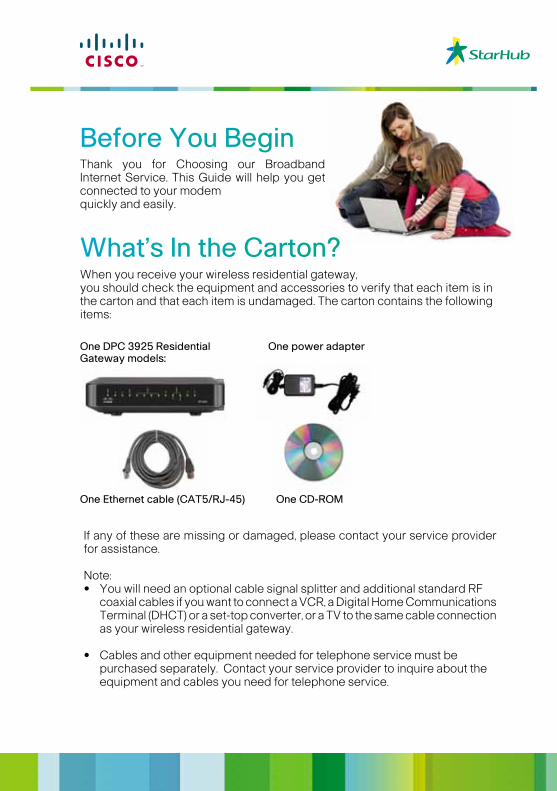
What’s In the Carton?
One DPC 3925 ResidentialGateway models:
One power adapter
One CD-ROMOne Ethernet cable (CAT5/RJ-45)
Page 5 of 11
Thank you for Choosing our Broadband Internet Service.
This Guide will help you get connected to your modem quickly and easily. When you receive your wireless residential gateway, you should check the equipment and accessories to verify that each item is in the carton and that each item is undamaged. The carton contains the following items:
If any of these are missing or damaged, please contact your service provider for assistance. Note: You will need an optional cable signal splitter and additional standard RF coaxial cables if you
want to connect a VCR, a Digital Home Communications Terminal (DHCT) or a set-top converter, or a TV to the same cable connection as your wireless residential gateway.
Cables and other equipment needed for telephone service must be purchased separately.
Contact your service provider to inquire about the equipment and cables you need for telephone service.
Page 6 of 11
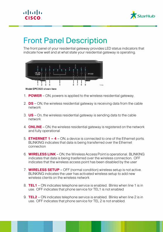
The front panel of your residential gateway provides LED status indicators that indicate how well and at what state your residential gateway is operating.
1. POWER – ON, powers is applied to the wireless residential gateway.
2. DS – ON, the wireless residential gateway is receiving data from the cable network 3. US – On, the wireless residential gateway is sending data to the cable network
4. ONLINE – ON, the wireless residential gateway is registered on the network and fully
operational 5. ETHERNET 1 – 4 – ON, a device is connected to one of the Ethernet ports. BLINKING indicates
that data is being transferred over the Ethernet connection 6. WIRELESS LINK – ON, the Wireless Access Point is operational. BLINKING indicates that data is
being trasferred over the wireless connection. OFF indicates that the wireless access point has been disabled by the user
7. WIRELESS SETUP – OFF (normal condition) wireless setup is not active. BLINKING indicates
the user has activated wireless setup to add new wireless clients on the wireless network 8. TEL1 – ON indicates telephone service is enabled. Blinks when line 1 is in use. OFF indicates
that phone service for TEL1 is not enabled 9. TEL2 – ON indicates telephone service is enabled. Blinks when line 2 is in use. OFF indicates
that phone service for TEL 2 is not enabled.
The front panel of your residential gateway provides LED status indicators that indicate how well and at what state your residential gateway is operating.
1. POWER – ON, powers is applied to the wireless residential gateway.
2. DS – ON, the wireless residential gateway is receiving data from the cable network
3. US – On, the wireless residential gateway is sending data to the cable network
4. ONLINE – ON, the wireless residential gateway is registered on the network and fully operational
5. ETHERNET 1 – 4 – ON, a device is connected to one of the Ethernet ports. BLINKING indicates that data is being transferred over the Ethernet connection
6. WIRELESS LINK – ON, the Wireless Access Point is operational. BLINKING indicates that data is being trasferred over the wireless connection. OFF indicates that the wireless access point has been disabled by the user
7. WIRELESS SETUP – OFF (normal condition) wireless setup is not active. BLINKING indicates the user has activated wireless setup to add new wireless clients on the wireless network
8. TEL1 – ON indicates telephone service is enabled. Blinks when line 1 is in use. OFF indicates that phone service for TEL1 is not enabled
9. TEL2 – ON indicates telephone service is enabled. Blinks when line 2 is in use. OFF indicates that phone service for TEL 2 is not enabled.
Front Panel Description
Page 7 of 11
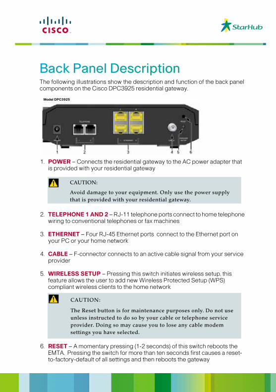
The following illustrations show the description and function of the back panel components on the Cisco DPC3925 residential gateway.
1. POWER – Connects the residential gateway to the AC power adapter that is provided with your
residential gateway
2. TELEPHONE 1 AND 2 – RJ-11 telephone ports connect to home telephone wiring to
conventional telephones or fax machines
3. ETHERNET – Four RJ-45 Ethernet ports connect to the Ethernet port on your PC or your home network
4. CABLE – F-connector connects to an active cable signal from your service provider 5. WIRELESS SETUP – Pressing this switch initiates wireless setup, this feature allows the user to
add new Wireless Protected Setup (WPS) compliant wireless clients to the home network
6. RESET – A momentary pressing (1-2 seconds) of this switch reboots the EMTA. Pressing the
switch for more than ten seconds first causes a reset-to-factory-default of all settings and then reboots the gateway
The following illustrations show the description and function of the back panel components on the Cisco DPC3925 residential gateway.
Back Panel Description
1. POWER – Connects the residential gateway to the AC power adapter that is provided with your residential gateway
2. TELEPHONE 1 AND 2 – RJ-11 telephone ports connect to home telephone wiring to conventional telephones or fax machines
3. ETHERNET – Four RJ-45 Ethernet ports connect to the Ethernet port on your PC or your home network
4. CABLE – F-connector connects to an active cable signal from your service provider
5. WIRELESS SETUP – Pressing this switch initiates wireless setup, this feature allows the user to add new Wireless Protected Setup (WPS) compliant wireless clients to the home network
6. RESET – A momentary pressing (1-2 seconds) of this switch reboots the EMTA. Pressing the switch for more than ten seconds first causes a reset- to-factory-default of all settings and then reboots the gateway
Page 7 of 11
The following illustrations show the description and function of the back panel components on the Cisco DPC3925 residential gateway.
1. POWER – Connects the residential gateway to the AC power adapter that is provided with your
residential gateway
2. TELEPHONE 1 AND 2 – RJ-11 telephone ports connect to home telephone wiring to
conventional telephones or fax machines
3. ETHERNET – Four RJ-45 Ethernet ports connect to the Ethernet port on your PC or your home network
4. CABLE – F-connector connects to an active cable signal from your service provider 5. WIRELESS SETUP – Pressing this switch initiates wireless setup, this feature allows the user to
add new Wireless Protected Setup (WPS) compliant wireless clients to the home network
6. RESET – A momentary pressing (1-2 seconds) of this switch reboots the EMTA. Pressing the
switch for more than ten seconds first causes a reset-to-factory-default of all settings and then reboots the gateway
Model DPC3925
CAUTION:
Avoid damage to your equipment. Only use the power supply that is provided with your residential gateway.
CAUTION:
The Reset button is for maintenance purposes only. Do not use unless instructed to do so by your cable or telephone service provider. Doing so may cause you to lose any cable modem settings you have selected.
How to Setup and Secure the DPC 3925DOCSIS 3.0 Cable Modem
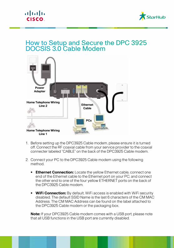
1. Before setting up the DPC3925 Cable modem, please ensure it is turned off. Connect the RF coaxial cable from your service provider to the coaxial connecter labeled “CABLE” on the back of the DPC3925 Cable modem.
2. Connect your PC to the DPC3925 Cable modem using the following method.
• Ethernet Connection: Locate the yellow Ethernet cable, connect one end of the Ethernet cable to the Ethernet port on your PC, and connect the other end to one of the four yellow ETHERNET ports on the back of the DPC3925 Cable modem.
• WiFi Connection: By default, WiFi access is enabled with WiFi security disabled. The default SSID Name is the last 6 characters of the CM MAC Address. The CM MAC Address can be found on the label attached to the DPC3925 Cable modem or the packaging box.
Note: If your DPC3925 Cable modem comes with a USB port, please note that all USB functions in the USB port are currently disabled.
PowerAdapter
Home Telephone WiringLine 2
Home Telephone WiringLine 1
EthernetCable
PCs
3. If you have a Telephone Service with your Service Provider, connect one end of a telephone jumper cable (not included) to a telephone outlet in your home or to a telephone or fax machine. Then connect the other end of the jumper cable to the appropriate RJ-11 TELEPHONE port on the back of the DPC3925 cable modem.
Notes: Make sure to connect your telephone service to the correct RJ-11 port. For single line telephone service, connect to port 1.
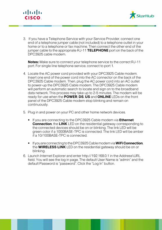
4. Locate the AC power cord provided with your DPC3925 Cable modem. Insert one end of the power cord into the AC connector on the back of the DPC3925 Cable modem. Then, plug the AC power cord into an AC outlet to power-up the DPC3925 Cable modem. The DPC3925 Cable modem will perform an automatic search to locate and sign on to the broadband data network. This process may take up to 2-5 minutes. The modem will be ready for use when the POWER, DS, US and ONLINE LEDs on the front panel of the DPC3925 Cable modem stop blinking and remain on continuously.
5. Plug in and power on your PC and other home network devices. • If you are connecting to the DPC3925 Cable modem via Ethernet Connection, the LINK LED on the residential gateway corresponding to the connected devices should be on or blinking. The link LED will be green color if a 1000BASE-TPC is connected. The link LED will be amber if a 10/100BASE-TPC is connected. • If you are connecting to the DPC3925 Cable modem via WiFi Connection, the WIRELESS LINK LED on the residential gateway should be on or blinking.6. Launch Internet Explorer and enter http://192.168.0.1 in the Address\URL field. You will see the log in page. The default User Name is “admin” and the default Password is “password”. Click the “Log In” button.
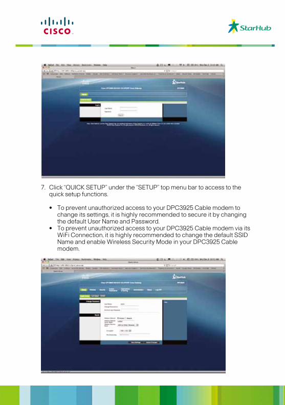
7. Click “QUICK SETUP” under the “SETUP” top menu bar to access to the quick setup functions.
• To prevent unauthorized access to your DPC3925 Cable modem to change its settings, it is highly recommended to secure it by changing the default User Name and Password. • To prevent unauthorized access to your DPC3925 Cable modem via its WiFi Connection, it is highly recommended to change the default SSID Name and enable Wireless Security Mode in your DPC3925 Cable modem.
Tips for Improved PerformanceCheck and Correct
If your residential gateway does not perform as expected, the following tips may help. If you need further assistance, contact your service provider.• Verify that the plug to your residential gateway AC power is properly inserted into an electrical outlet. • Verify that your residential gateway AC power cord is not plugged into an electrical outlet that is controlled by a wall switch. If a wall switch controls the electrical outlet, make sure the switch is in the ON position.• Verify that the ONLINE LED status indicator on the front panel of your residential gateway is illuminated.• Verify that your cable service is active and that it supports two-ways service.• Verify that all cables are properly connected, and that you are using the correct cables.• Verify that your TCP / IP is properly installed and configured if you are using the Ethernet connection.• Verify that you have called your service provider and given them the serial number and MAC address of your residential gateway.• If you are using a cable signal splitter so that you can connect the residential gateway to other devices, remove the splitter and reconnect the cables so that residential gateway is connected directly to the cable input. If the residential gateway now functions properly, the cable signal splitter may be defective and may need to be replaced.• For best performance over an Ethernet connection, your PC should be equipped with a Gigabit Ethernet card.