Embed Size (px)
Citation preview

User Guide OI/FET100–EN Rev. C
WaterMaster FET100Electromagnetic flowmeterTransmitter
The perfect fit for all water industry applications
Introduction
WaterMaster™ is a range of high performance electromagnetic flowmeters for the measurement of electrically-conductive fluids and systems are normally supplied factory-configured and calibrated.
This User Guide provides installation, connection, security, start-up and basic setup details. For programming and configuration information refer to the Programming Guide – IM/WMP.
This User Guide should be used in conjunction with the following publications:
– Programming Guide – IM/WMP
– User Guide Supplement, PROFIBUS RS485 Physical Layer (FEX100–DP) – IM/WMPBS–EN
– User Guide Supplement, PROFIBUS FEX100-DP Parameter Tables – IM/WMPBST–EN
– User Guide Supplement, MODBUS RS485 Physical Layer (FEX100–MB) – COI/FEX100/MOD–EN
– User Guide Supplement, MODBUS Tables – COI/FEX100/MOD/TBL–EN

The CompanyWe are an established world force in the design and manufacture of instrumentation for industrial process control, flow measurement, gas and liquid analysis and environmental applications.
As a part of ABB, a world leader in process automation technology, we offer customers application expertise, service and support worldwide.
We are committed to teamwork, high quality manufacturing, advanced technology and unrivalled service and support.
The quality, accuracy and performance of the Company’s products result from over 100 years experience, combined with a continuous program of innovative design and development to incorporate the latest technology.
Quality Control
The UKAS Calibration Laboratory No. 0255 is just one of the ten flow calibration plants operated by the Company and is indicative of our dedication to quality and accuracy.
UKAS Calibration Laboratory No. 0255
����

WaterMaster FET100Electromagnetic floweter | Transmitter
OI/FET100–EN Rev. C 1
1 Safety ............................................................................................................................................... 21.1 Electrical Safety ............................................................................................................................................. 21.2 Symbols ........................................................................................................................................................ 21.3 Health & Safety ............................................................................................................................................. 3
2 Mechanical Installation .................................................................................................................... 42.1 Installation Conditions ................................................................................................................................... 42.2 Dimensions ................................................................................................................................................... 6
3 Electrical Installation ....................................................................................................................... 83.1 Remote Transmitter / Sensor Arrangement ................................................................................................... 83.2 Transmitter Terminal Connections ............................................................................................................... 103.3 Cable Preparation (Remote Systems Only) .................................................................................................. 113.4 Transmitter / Sensor Cable Connections ..................................................................................................... 12
3.4.1 Sensor Cable Terminal Connections and Recommended Cable Lengths ...................................... 123.5 Output Connections .................................................................................................................................... 13
3.5.1 Frequency Outputs ....................................................................................................................... 133.5.2 Alarm Outputs .............................................................................................................................. 153.5.3 Contact Input ............................................................................................................................... 163.5.4 PLC Interface ............................................................................................................................... 173.5.5 Current Output (4 to 20 mA) – HART (FEX100) Variant .................................................................. 183.5.6 RS485 Communications – PROFIBUS (FEX100-DP)
and MODBUS (FEX100-MB) Variants ........................................................................................... 183.5.7 Test Point Access ......................................................................................................................... 18
3.6 Power Supply Connections ......................................................................................................................... 203.6.1 AC Power Supply ......................................................................................................................... 203.6.2 DC (and Low Voltage AC) Power Supply ...................................................................................... 213.6.3 Configuration DIP Switches .......................................................................................................... 22
3.7 Refitting the Cartridge and Cover ................................................................................................................ 22
4 Start-up and Operation ................................................................................................................. 244.1 Navigating the Menus and Parameters ........................................................................................................ 244.2 Start-up Screens ......................................................................................................................................... 254.3 Security Levels and Password Access ........................................................................................................ 27
4.3.1 Default Passwords ....................................................................................................................... 284.3.2 Entering Passwords ...................................................................................................................... 28
4.4 Easy Setup ................................................................................................................................................. 29
5 Specification .................................................................................................................................. 31

WaterMaster FET100Electromagnetic floweter | Transmitter 1 Safety
1 SafetyInformation in this manual is intended only to assist our customers in the efficient operation of ourequipment. Use of this manual for any other purpose is specifically prohibited and its contents are not to bereproduced in full or part without prior approval of the Technical Publications Department.
1.1 Electrical SafetyThis equipment follows, obeys the requirements of CEI/IEC 61010-1:2001-2 'Safety Requirements forElectrical Equipment for Measurement, Control and Laboratory Use' and follows, obeys NIST and OSHA.
If the equipment is used in a manner NOT specified by the Company, the protection provided by theequipment may be impaired.
1.2 SymbolsOne or more of the following symbols may appear on the equipment labeling:
Warning – Refer to the manual for instructions Direct current supply only
Caution – Risk of electric shock Alternating current supply only
Protective earth (ground) terminal Both direct and alternating current supply
Earth (ground) terminal The equipment is protected through double insulation
2 OI/FET100–EN Rev. C

WaterMaster FET100Electromagnetic floweter | Transmitter 1 Safety
1.3 Health & Safety
Health and Safety
To ensure that our products are safe and without risk to health, the following points must be noted:
The safety requirements of this equipment, any associated equipment and the local environment must be taken into consideration during installation.
Install and use this equipment and any associated equipment in accordance with the relevant national and local standards.
The relevant sections of these instructions must be read carefully before proceeding.
Warning labels on containers and packages must be observed.
Installation, operation, maintenance and servicing must only be carried out by suitably trained personnel and in accordance with the information given.
Normal safety precautions must be taken to avoid the possibility of an accident occurring when operating in conditions of high pressure and / or temperature.
Chemicals must be stored away from heat, protected from temperature extremes and powders kept dry. Normal safe handling procedures must be used.
When disposing of chemicals ensure that no two chemicals are mixed.
Product liability – advice and assistance provided without charge is given in good faith but without liability.
Safety advice concerning the use of the equipment described in this manual or any relevant hazard data sheets (where applicable) may be obtained from the Company address on the back cover, together with servicing and spares information.
Warning.
System configuration must be carried out only by users or personnel with approved access rights(user privileges).
Read all relevant sections of this guide before configuring the system or modifying systemparameters.
Install and use associated equipment in accordance with the relevant national and localstandards.
OI/FET100–EN Rev. C 3

WaterMaster FET100Electromagnetic floweter | Transmitter 2 Mechanical Installation
2 Mechanical Installation
2.1 Installation Conditions
Fig. 2.1 Siting
Fig. 2.2 Within Temperature Limits
Fig. 2.3 Shade
Allow room to read display
60 °C (140 °F) Max.
–20 °C(–4 °F)
Min.
4 OI/FET100–EN Rev. C
WaterMaster FET100Electromagnetic floweter | Transmitter 2 Mechanical Installation
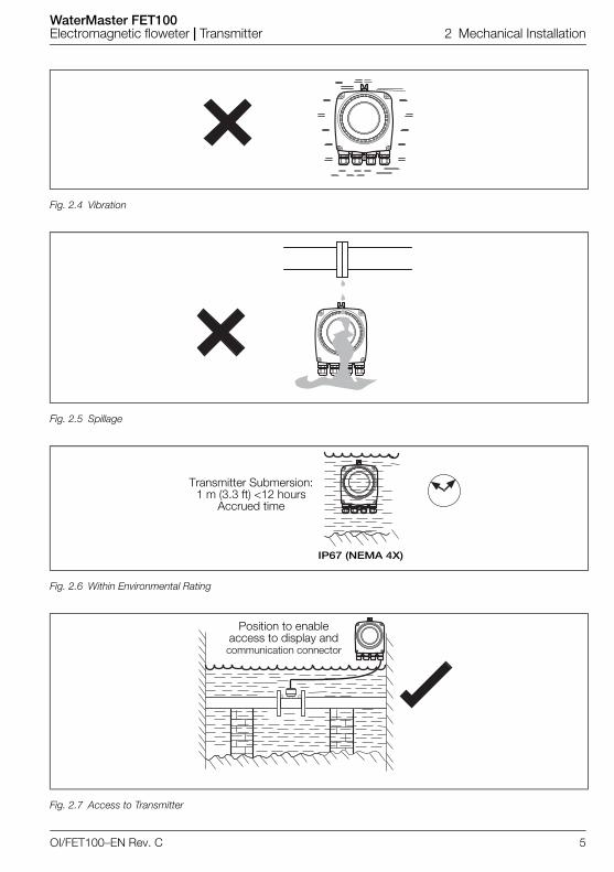
Fig. 2.4 Vibration
Fig. 2.5 Spillage
Fig. 2.6 Within Environmental Rating
Fig. 2.7 Access to Transmitter
IP67 (NEMA 4X)
Transmitter Submersion: 1 m (3.3 ft) <12 hours
Accrued time
Position to enable access to display and communication connector
OI/FET100–EN Rev. C 5
WaterMaster FET100Electromagnetic floweter | Transmitter 2 Mechanical Installation
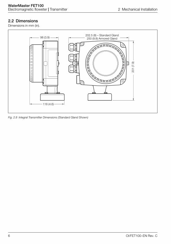
2.2 DimensionsDimensions in mm (in).
Fig. 2.8 Integral Transmitter Dimensions (Standard Gland Shown)
118 (4.6)
98 (3.9)202.5 (8) – Standard Gland250 (9.8) Armored Gland
201
(7.9
)
6 OI/FET100–EN Rev. C

WaterMaster FET100Electromagnetic floweter | Transmitter 2 Mechanical Installation
Fig. 2.9 Remote Transmitter Dimensions (Standard Gland Shown)
Note. Fix remote transmitter to a secure surface using 3 x M5 screws (not supplied).
202.
5 (8
) – S
tand
ard
Gla
nd25
0 (9
.8) A
rmor
ed G
land
98 (3.9) R3.2 (0.1 )
71 (2.8)
179
(7.0
)
OI/FET100–EN Rev. C 7

WaterMaster FET100Electromagnetic floweter | Transmitter 3 Electrical Installation
3 Electrical Installation
3.1 Remote Transmitter / Sensor Arrangement
Note. For bonding connections use 4mm2 (< 10AWG) cable.
Fig. 3.1 Remote Transmitter in Roadside Cabinet – Flanged Sensor
Power Supply
8 OI/FET100–EN Rev. C

WaterMaster FET100Electromagnetic floweter | Transmitter 3 Electrical Installation
Fig. 3.2 Remote Transmitter in Roadside Cabinet – Probe Sensor
Power Supply
OI/FET100–EN Rev. C 9

WaterMaster FET100Electromagnetic floweter | Transmitter 3 Electrical Installation
3.2 Transmitter Terminal Connections
Referring to Fig. 3.3:
1. Slacken (but do not remove) the four transmitter cover screws A.
2. Remove the transmitter cover.
3. Check that the power indicator LED B on the backplane is not lit.
4. If screws C are not visible, access them by gently pulling the rotation lock D back and rotating thecartridge E until the cartridge screw access holes align with the cartridge screw heads.
5. Slacken the three cartridge screws and lift the cartridge F away from the housing.
Warning. Isolate the transmitter from power supplies before removing the cover.
Fig. 3.3 Accessing the Transmitter Terminals
Warning. If the power indicator LED B is lit, the transmitter is still powered up. Beforecontinuing, isolate the transmitter power supply.
10 OI/FET100–EN Rev. C

WaterMaster FET100Electromagnetic floweter | Transmitter 3 Electrical Installation
3.3 Cable Preparation (Remote Systems Only)To prepare the cable for connection at the transmitter and sensor terminal blocks:
1. Remove the outer cable insulation and Mylar® wrap.
2. Ensure the drain wire is sleeved.
3. Cut the cable connection wires to the lengths shown in Fig 3.5, page 12.
Fig. 3.4 Cable Gland / Conduit Entry (Remote Transmitter Shown)
AC/DC PowerSupply Terminal
Power Cable Output Connections
External Earth
Output Connections Sensor Cable
Output Connections Terminal
Sensor Cable Terminal
Backplane
Internal Earth(Alternative PE)Internal Earth
(Alternative PE)
Test Points for Output Connections
OI/FET100–EN Rev. C 11

WaterMaster FET100Electromagnetic floweter | Transmitter 3 Electrical Installation
3.4 Transmitter / Sensor Cable Connections
3.4.1 Sensor Cable Terminal Connections and Recommended Cable Lengths
Caution.
Make connections only as shown.
Twist the screen wire of D1 / TFE + D2 with the outer screen drain wire and sleeve them.
For standard (non-cathodically protected) systems, connect the drain wire to the earth screw.
For cathodically protected systems, connect the drain wire to terminal SCR, ensuring no braid or wires touch the exposed copper areas within the transmitter sensor cable wiring area.
If an earth screw is not available at the transmitter enclosure, connect the drain wire to terminal SCR.
Ensure the seal and mating surfaces are clean to maintain environmental rating.
Conduit connections must provide cable entry sealing.
Ensure cable glands are tightened after wiring. Do not overtighten the plastic cable glands to avoid destroying their sealing properties. Initially, tighten finger-tight, then a further 1/2 to 3/4 turn using a suitable spanner or wrench.
Fit blanking plugs where required.
Fig. 3.5 Sensor Cable Connections at Transmitter Terminal Block – Standard System
Refer to Section 3.3, page 11 for cable preparation requirements before connecting cable
**Drain Wire(Twisted withScreen from
D1/TFE – Orangeand D2 – Yellow)
*Inner wire**For cathodically protected systems (or if the transmitter enclosure does not have an earth screw) connect the drain wire to terminal SCR.
M1Brown
M2Red
SCRScreen
D1/TFEOrange
D2Yellow
3Green
(Sleeve)
S2Blue
(Screen)
S1Violet
(Screen)
E2Blue
(*Signal)
E1Violet
(*Signal)
Cut cables to 70 mm (2.75 in) Cut cables to 60 mm (2.35 in)
12 OI/FET100–EN Rev. C

WaterMaster FET100Electromagnetic floweter | Transmitter 3 Electrical Installation
3.5 Output Connections
3.5.1 Frequency Outputs
Caution.
Inductive loads must be suppressed or clamped to limit voltage swings.
Operation of outputs is programmable.
External isolators are not normally required as the pulse and alarm circuit is electrically separatedfrom all other WaterMaster connections.
Fig. 3.6 PLC / Datalogger Connections
Note. Digital outputs DO1 and DO2 are polarity sensitive. The common (negative) connection for theseoutputs is designated 'COM'.
XX XX XX XX 42 41 51 61 52 62
PLC or Datalogger
COM DO1 DO2Terminal connection IDs are HART- / PROFIBUS-variant
dependent
OI/FET100–EN Rev. C 13

WaterMaster FET100Electromagnetic floweter | Transmitter 3 Electrical Installation
Fig. 3.7 Electromechanical Connections
Fig. 3.8 Telemetry / Electronic Counters (etc.) Connections
+–
1 2 3 4 5 6
1 2 3 4 5 6
XX XX XX XX 42 41 51 61 52 62
DC Supply
Reverse Flow Output (DO2) Counter / Totalizer
Forward Flow Output (DO1) Counter / Totalizer
and / or
COM DO1 DO2
1 2 3 4 5 6
1 2 3 4 5 6XX XX XX XX 42 41 51 61 52 62
+–
+–
and / or
COM DO1 DO2
Reverse Flow Output (DO2) Counter / Totalizer
Forward Flow Output (DO1) Counter / Totalizer
14 OI/FET100–EN Rev. C

WaterMaster FET100Electromagnetic floweter | Transmitter 3 Electrical Installation
3.5.2 Alarm Outputs
Fig. 3.9 Alarm Output Connections
Fig. 3.10 Alarm Output Connections
Note.
Normal alarm / logic output is from DO3 (terminal 61). DO1 (41) and DO2 (51) can also be configured as alarms if required but are then NOT available as frequency / pulse outputs as shown in Figs 3.7 and 3.8).
Bell and horn shown for example only. Any suitable alarm device may be used (for example, lamp, siren, buzzer etc.).
COM DO3Terminal connection IDs are
HART- / PROFIBUS- / MODBUS-
variant dependent
XX XX XX XX 42 41 51 61 52 62
+
–DC Supply
COM DO1 DO2
Alarm 1
Alarm 2
and / or
Bell
HornDO3
OI/FET100–EN Rev. C 15

WaterMaster FET100Electromagnetic floweter | Transmitter 3 Electrical Installation
3.5.3 Contact Input
Fig. 3.11 Relay and Timers Output Connections
Note. Relay and timer switch shown for example only. Connect as required.
Fig. 3.12 Open Collector (or Grounded Contact) Connections
XX XX XX XX 42 41 51 61 52 62
+
–
COM DO1 DO2
DC Supply
Alarm 1
Alarm 2
Relay
Timer Switch
R
and / or
XX XX XX XX 42 41 51 61 52 62
+
–
COM DO1 DO2
Controller with Open Collector Output
16 OI/FET100–EN Rev. C

WaterMaster FET100Electromagnetic floweter | Transmitter 3 Electrical Installation
3.5.4 PLC Interface
Fig. 3.13 PLC – Common –ve Connections
Fig. 3.14 PLC – Common +ve Connections
Note.
WaterMaster digital outputs are NPN optocoupled transistors used as switches.
Maximum allowed voltage at collector is 30 V DC
Maximum allowed current across transistor is 220 mA.
XX XX XX XX 42 41 51 61 52 62 +
–
Fwd +
PLCTypically1k 1W
DC SupplyRev +
COM
Com
24 V
DO1 DO2
XX XX XX XX 42 41 51 61 52 62
+
–
DC Supply
PLC
Fwd –
Rev –
Com
COM DO1 DO2
OI/FET100–EN Rev. C 17

WaterMaster FET100Electromagnetic floweter | Transmitter 3 Electrical Installation
3.5.5 Current Output (4 to 20 mA) – HART (FEX100) Variant
3.5.6 RS485 Communications – PROFIBUS (FEX100-DP) and MODBUS (FEX100-MB) Variants
3.5.7 Test Point Access
Fig. 3.15 Current Output (4 to 20 mA) – HART (FEX100) Variant
Fig. 3.16 WaterMaster RS485 Backplane Connections to PROFIBUS / MODBUS Networks
Note. A typical DVM probe can access (fit) the PCB's test holes.
+ –Refer to IM/WMP for
HART-Protocol communication details
PROFIBUS / MODBUSRS485
A1 / B1 – InA2 / B2 – Out
Screen Clamp
18 OI/FET100–EN Rev. C

WaterMaster FET100Electromagnetic floweter | Transmitter 3 Electrical Installation
*These 2 test points are connected on the HART FEX100 backplane only (they are present on the PROFIBUS FEX100-DP / MODBUS FEX100-MB backplane but are notconnected)
Fig. 3.17 Transmitter PCB Board Test Point Access
�� �� ��
����
�����
IC+*IC–*
Not Used
O/P1
4 to 20 mA
COMO/P2
O/P3 Alarm Output
Not Used
Frequency Outputs
OI/FET100–EN Rev. C 19

WaterMaster FET100Electromagnetic floweter | Transmitter 3 Electrical Installation
3.6 Power Supply Connections
3.6.1 AC Power Supply
Warning.
Electrical installation and earthing (grounding) must be in accordance with relevant national andlocal standards.
Power must be connected via a suitable isolator and fused in accordance with relevant standards.
When changing fuses F1 or F2, isolate the power supply and wait 20 seconds before opening theenclosure.
Replace fuses with the correct part – see Fig 3.18 (AC power) and 3.19, page 21 (DC power).
Fig. 3.18 AC Power Supply Connections
Transmitter Label
External Earth ScrewAC power via asuitable isolator
and fuse
*AC Fuse F1 250 mA Type T(see table below for suppliers)
>4 mm2 (<10 AWG) Copper Wire
Power Supply Indicator LED
**Can be used as a Protective Earth (PE) if required by national standardsBrown
BlueGreen / Yellow
Internal Earth Screws**
*Fuse Supplier Fuse Part Number
ABB B20411
Bussmann BK/ETF 250 mA Wickmann 19372 K250mA
20 OI/FET100–EN Rev. C

WaterMaster FET100Electromagnetic floweter | Transmitter 3 Electrical Installation
3.6.2 DC (and Low Voltage AC) Power Supply
Fig. 3.19 DC (and Low Voltage AC) Power Supply Connections
Transmitter Label (DC)
DC (or Low Voltage AC) powervia suitable Isolator and fuse
External Earth
>4 mm2 (<10 AWG) Copper Wire
Internal Earth Screws
*DC Fuse F2 2 A Type T(see table below for suppliers)
Power Supply Indicator LED
RedBlack
Green / Yellow
*Fuse Supplier Fuse Part Number
ABB B20412
Bussmann BK/ETFZM Wickmann 19372 K2A
OI/FET100–EN Rev. C 21

WaterMaster FET100Electromagnetic floweter | Transmitter 3 Electrical Installation
3.6.3 Configuration DIP SwitchesThree configuration DIP switches are mounted on the transmitter backplane board.
These are factory-set as follows:
Remote transmitter – all OFF
Integral transmitter – SW3 ON
For MID-compliant flowmeters set the read-only / MID protection switch to 'ON' to ensure the meter issecure from tampering.
For HART software versions prior to 01.02.XX, this switch (set after commissioning) prevents login via thekeypad or bus at any security level.
From HART software version 01.03.XX onwards and for all PROFIBUS software versions, on MID meters,all metrological-related parameters are locked and inaccessible at the Service level. Standard andAdvanced user level parameters can still be modified via the HMI or bus.
3.7 Refitting the Cartridge and Cover
Fig. 3.20 Configuration DIP Switches
Warning. Ensure the transmitter is isolated from power supplies before refitting the cover.
Caution.
The communications bus type is HART FEX100 if not specified on thecartridge label. An example of the PROFIBUS FEX100-DP variant cartridgelabel is shown on the right.
The cartridge communications type must match the communications type of the transmitter backplane PCB.
To avoid damaging the cartridge during refitting, do not overtighten the cartridge screws.
ConfigurationDIP Switches
SW3 SW2 SW1
OFF
ON
SW1 – Read-only / MID Protection
SW2 – (Future Product)
SW3 – Internal Sensor Memory
DIP Switch Functions
PROFIBUS variant cartridge label
22 OI/FET100–EN Rev. C

WaterMaster FET100Electromagnetic floweter | Transmitter 3 Electrical Installation
Referring to Fig. 3.21:
1. Confirm that the cartridge to be fitted is of the correct power supply and for the correctcommunications bus type (HART, PROFIBUS OR MODBUS) by checking the label A on the side ofthe cartridge:
– AC cartridges have one black label on the cartridge side.
– DC (and low voltage AC) cartridges have two red DC labels – one on the cartridge side andone on the cartridge rear plate.
2. Align the three cartridge screws B with the cartridge housing pillars and tighten the screws carefullyuntil the cartridge is held in position.
3. If necessary, rotate the cartridge to the required orientation before refitting the cover – see Fig. 3.3,page 10 for details.
4. For high integrity / security installations, set DIP switch SW1 to the 'ON' (Read-only) position – seeFig. 3.20, page 22.
5. Align the transmitter cover with the housing and tighten the four cover screws C carefully.
6. For high integrity / security installations or where MID is required, fit anti-tamper seals to the securityfixtures D.
Fig. 3.21 Refitting the Cartridge and Cover
�
�
�
�
�
�
�
�
�
���
����
�� ��������������
�������
�� ��������������
���
Black Label on AC Cartridge
Red Label On DC (and Low Voltage AC) CartridgeRear Plate
Red Label on DC (and Low Voltage AC) Cartridge
OI/FET100–EN Rev. C 23

WaterMaster FET100Electromagnetic floweter | Transmitter 4 Start-up and Operation
4 Start-up and Operation
4.1 Navigating the Menus and ParametersThe four keys below the display are used to navigate through the menus and to execute all systemcommands and selections.
Note. This section describes the options available at the 'Easy Setup' menu. Refer to the ProgrammingManual (IM/WMP) for comprehensive details of all end-user menus and operating levels.
Fig. 4.1 Display and Keys
Item Description
A Screen title at the current level / parameter
B Main level icon
C Menu level title
D Prompt executed by pressing the key
E Prompt executed by pressing the key
F Left key – used for parameter navigation and to enter editable parameters
G Up / Down keys – used to scroll through menu options and to increase / decrease values in editable parameters
H Right key – used to accept / select parameter values / selections and exit sub-levels
�
�
� �
�
�
�
Menu
Easy Setup
Exit Select
24 OI/FET100–EN Rev. C

WaterMaster FET100Electromagnetic floweter | Transmitter 4 Start-up and Operation
4.2 Start-up ScreensAt start-up, the type of screen displayed indicates the status of the system.
There are four common start-up screen types as follows:
System Start-up
At system start-up, a progress bar is displayed for the duration of the start-up period.
After this period, one of the four following screens is displayed according to the current status of the system.
No Sensor Connected
If no sensor is detected during start-up, an auto-recovery routine is run to look for the sensor. If no sensor is detected, this routine continues until it is stopped manually.
If 'Offline' is selected during auto-recovery (by pressing the key) the transmitter ceases to operate as a flowmeter and
the following conditions apply at the transmitter:
Plant and transmitter data can be configured.
Sensor data cannot be configured.
Note. If this screen is displayed on an integral transmitter, check that DIP switch SW3 is in the 'ON' position (refer to Fig. 3.20, page 22).
Dual Sensor Memory
Integral and retrofit systems have the sensor memory mounted on the transmitter backplane board.
If two sensor memory types (integral and remote) are detected at start-up, the warning 'DUAL SENSOR MEMORY' is displayed.
To correct this condition, set DIP switch SW3 to the 'OFF' position (refer to Fig. 3.20, page 22).
System Startup
LOADING SYSTEM DATA
System Startup
NO SENSOR DETECTED
Device Resetting
Offline
System Startup
DUAL SENSOR MEMORY
Rectify & Reset
OK
OI/FET100–EN Rev. C 25

WaterMaster FET100Electromagnetic floweter | Transmitter 4 Start-up and Operation
Installation Changed
If the sensor data stored in the transmitter memory does not match the data of the connected sensor, the warning 'INSTALLATION CHANGED' is displayed.
The changed item(s) (transmitter or sensor) can be identified and data copied as follows:
Transmitter
Selecting this option copies plant and stack data from the sensor memory to the transmitter memory and loads the totalizer from the sensor memory.
It is used to make the following changes:
Remote or integral cartridge change
Remote Tx change
New installation
Sensor
Selecting this option copies data from the transmitter memory to the sensor and loads the totalizer from the sensor memory.
It is used to make the following changes:
Integral backplane change
Sensor change
Integral transmitter change
Process Display (Operator Page)
When the 'Process Display' (Operator Page) is displayed, normal operation is assumed.
To access menus at a permitted access level, press the key to display the 'Access Level' screen – see Section 4.3, page 27.
*Example legend only
System Startup
INSTALLATION CHANGED
Identify Changed Item
SensorTransmitter
Drain Water
123.45 l/s
*
26 OI/FET100–EN Rev. C

WaterMaster FET100Electromagnetic floweter | Transmitter 4 Start-up and Operation
4.3 Security Levels and Password AccessAt power-up, the 'Start-up Display' and 'Process Display' screens are activated in sequence.
Note.
Passwords at 'Standard' and 'Advanced' level can be set and changed by end-users.
Access to the 'Service' level is reserved for factory-only personnel and not available to end-users.
To navigate from the 'Operator Page(s)' directly back to the menus, accept the default accesslevel selection at the 'Access Level' screen and press the key.
*Example legend only
Operator Pages (Process Display)
When the start-up routine is completed, and if no changes have occurred since last start-up, the 'Process Display' (Operator Page) screen is displayed.
Press the key to display the 'Access Level' screen where the level of user access is selected.
Access Level
Passwords are required for 'Standard' and 'Advanced' level access. Passwords are not required for 'Read Only' access.
Select the permitted level of access and press the key to display the 'Enter Password' screen (the 'Enter Password' screen is bypassed if 'Read Only' is selected).
Enter Password
Enter the password and press the key to display menus available at the permitted access level.
Note. If a time-out occurs (5 minutes of no activity), enter the password again to access the menus.
123.45 l/s
Drain Water*
Access Level
Read OnlyStandard AdvancedService
Back Select
Next OK
Enter Password
OI/FET100–EN Rev. C 27

WaterMaster FET100Electromagnetic floweter | Transmitter 4 Start-up and Operation
4.3.1 Default PasswordsThe WaterMaster transmitter is supplied with default passwords for access to 'Standard' and 'Advanced'level menus.
The two passwords are:
'Standard' access password: 2 or blank
'Advanced' access password: 3 or blank
Passwords can contain up to 5 characters and are not case sensitive.
To prevent unauthorized access ABB recommend the default passwords are changed on commissioning.
4.3.2 Entering PasswordsTo select password characters and enter passwords:
1. Scroll to the 'Access Level' screen and select the required access level. Press the key to displaythe 'Enter Password' screen.
2. Use the and keys to scroll to and highlight the first password character to be selected.
3. Press the key to select the highlighted character (add it to the password set).
4. Use the and keys to highlight the next password character to be selected.
5. Repeat steps 2 to 4 until all characters have been added to the password.
6. Press the key to accept the password and display menus available at the requested access level.
Note. When allocating passwords, record a copy of each password and store in a safe location. It is notpossible to interrogate the transmitter to 'recover' passwords once they have been set.
28 OI/FET100–EN Rev. C

WaterMaster FET100Electromagnetic floweter | Transmitter 4 Start-up and Operation
4.4 Easy Setup
Easy Setup
The 'Easy Setup' level is used to set the system up quickly and contains a series of options for users with 'Standard' and 'Advanced' access permission. Users with 'Read Only' access cannot make selections at this level.
To navigate the 'Easy Setup' parameters:
Enter 'Easy Setup' by pressing the key at the 'Select' prompt.
View and edit a parameter by pressing the key at the 'Edit' prompt.
Scroll parameter options by pressing the and keys (press and retain contact to scroll multiple options consecutively).
Edit parameters by pressing the key at the 'Next' prompt to enter the text field and press the and keys to increase or decrease the value. Press the key at the 'OK' prompt to accept
the new value.
Accept a highlighted parameter by pressing the key at the 'OK' prompt.
Exit the current parameter without changing the setting by pressing the key at the 'Cancel' prompt.
Move to the next parameter by pressing the key at the 'Next' prompt.
Exit 'Easy Setup' level by pressing the key at the 'Exit' prompt on the 'Easy Setup' main level screen.
�Menu
Exit Select
Easy Setup
OI/FET100–EN Rev. C 29

WaterMaster FET100Electromagnetic floweter | Transmitter 4 Start-up and Operation
* For OIML and MID flowmeters, only m3 must be used.
Parameter Range [Default] NoteLanguage English, Deutsch, Français, Español,
Italiano, Polski, Portuguese[English] Selectable
Q (Flowrate) Unit m3/s, m3/min, m3/h, m3/d, ft3/s, ft3/min, ft3/h, ft3/d, ugal/s, ugal/min, ugal/h, ugal/d, Mugal/d, igal/s, igal/min, igal/h, igal/d, bls/s, bls/min, bls/h, bls/d, hl/h, ml/s, ml/min, l/s, l/min, l/h, Ml/d,
[m3/h] Selectable
Qmax Dependent on sensor size [Factory set]
Volume & Pulse Unit m3, l, ml, ft3, hl, igal, ugal, bls, MI, Mugal Selectable*
Pulse Width 0.09 to 2000.00 ms [0.09 ms] Editable
Pulses / Unit 0.000010 to 10,000,000 pulses / unit [1.0] Editable(Only shown when Pulse Mode is Pulse / Unit)
Fullscale Frequency 0.250000 to 10,000,000 Hz [5,000.000] Editable(Only shown when Pulse Mode is Fullscale Frequency)
Damping 0.02 to 60 s [3.00 s] Editable
Mains Frequency 50 or 60 Hz [50 Hz] Selectable
30 OI/FET100–EN Rev. C

WaterMaster FET100Electromagnetic floweter | Transmitter 5 Specification
5 Specification
Functional Specification
Power supply
Supply voltage fluctuations within the specified range have no effect on accuracy
Digital outputs (3 off)Rating 30 V @ 220 mA, open collector, galvanically isolated
Maximum output frequency 5250 Hz
1 off dedicated to Alarm / Logic, programmable function
2 off configurable to either Pulse / Frequency or Alarm/Logic function
Current output – HART FEX100 variant4 to 20 mA or 4 to 12/20 mA, galvanically isolated
Maximum loop resistance 750
HART protocol Version 5.7 (HART registered)
Signal levels compliant with NAMUR NE 43 (3.8 to 20.5 mA)
Low alarm 3.6 mA, High alarm 21.8 mA
Additional accuracy
RS485 communications – PROFIBUS FEX100-DP variant Registered name: FEX100-DP
RS485 (9.6kbps to 1.5Mbps), galvanically isolated
DPV0, DPV1
PA Profile 3.01
Standard idents: 9700, 9740, 9741
FEX100-DP specific ident: 3431
3 Concurrent MS2 master connections
RS485 communications – MODBUS FEX100-MB variant MODBUS RTU protocol
RS485 (9.6kbps to 115.2kbps), galvanically isolated
Electrical connections20 mm glands, 1/2 in NPT, 20 mm armored glands
Temperature limitations
Mains 85 to 265 V AC @ <7 VA
Low voltage 24 V AC +10 %/–30 % @ <7 VA
DC 24 V ±30 % @ <0.4 A
±0.1 % of reading
Temperature coefficient: typically <±20 ppm/°C
Ambient temperature –20 to 60 °C (–4 to 140 °F)
Temperature coefficient Typically <±10 ppm/°C @ Vel 0.5 mls
OI/FET100–EN Rev. C 31

WaterMaster FET100Electromagnetic floweter | Transmitter 5 Specification
Environmental protectionHumidity: 0 to 100 %
Rating: IP67 (NEMA 4X) to 1m (3.3 ft) depth
Tamper-proof securityWrite access prevented by internal switch combined with external security seals for MID applications
LanguagesEnglish, French, German, Italian, Spanish, Polish
Infrared service portUSB adapter (accessory), USB 1.1. and 2.0 compatible
Driver software for Windows 2000, XP, 7 (32-bit) and Vista
Housing materialPowder-coated aluminium with glass window
Hazardous approvals (HART variant only)FM & FMc Class 1 Div 2
(FM listing NI / 1 / 2 / ABCD / T4, S / II, III / 2 / FG /T4,Ta=60C; Type 4X, IP67 – for transmitter and integral mountingTa=70C, Type 6P, IP68 – for remote sensor type, IP67 on DN10 to 32)
(FMc listing NI / 1 / 2 / ABCD / T4, DIP / II, III / 2 / FG /T4,Ta=60C; Type 4X, IP67 – for transmitter and integral mountingTa=70C, Type 6P, IP68 – for remote sensor type, IP67 on DN10 to 32)
FET, FEV, FEW and FEF DN700 to 2200 (27/28* to 84) only
*Size is dependent on flange specification
Declaration of ConformanceCopies of CE and PED certification will be available on request.
WaterMaster has OIML R49 Certificate of Conformity to accuracy class 1 and 2 (FEV DN40 to 200). Copies of accuracycertification are available on request.
WaterMaster (FEV DN40 to 200) has been type examined under directive MID 2004/22/EC, Annex MI-001. Copies ofthis certificate are available on request.
DS/WM–EN Rev. K
32 OI/FET100–EN Rev. C

Products and customer support
Automation SystemsFor the following industries:— Chemical & Pharmaceutical— Food & Beverage— Manufacturing— Metals and Minerals— Oil, Gas & Petrochemical— Pulp and Paper
Drives and Motors— AC and 6 Drives, AC and DC Machines, AC Motors to
1kV— Drive Systems— Force Measurement— Servo Drives
Controllers & Recorders— Single and Multi-loop Controllers— Circular Chart and Strip Chart Recorders— Paperless Recorders— Process Indicators
Flexible Automation— Industrial Robots and Robot Systems
Flow Measurement— Electromagnetic Flowmeters— Mass Flowmeters— Turbine Flowmeters— Wedge Flow Elements
Marine Systems & Turbochargers— Electrical Systems— Marine Equipment— Offshore Retrofit and Refurbishment
Process Analytics— Process Gas Analysis— Systems Integration
Transmitters— Pressure— Temperature— Level— Interface Modules
Valves, Actuators and Positioners— Control Valves— Actuators— Positioners
Water, Gas & Industrial Analytics Instrumentation— pH, Conductivity and Dissolved Oxygen Transmitters
and Sensors— Ammonia, Nitrate, Phosphate, Silica, Sodium,
Chloride, Fluoride, Dissolved Oxygen and Hydrazine Analyzers
— Zirconia Oxygen Analyzers, Katharometers, Hydrogen Purity and Purge-gas Monitors, Thermal Conductivity
Customer supportWe provide a comprehensive after sales service via a Worldwide Service Organization. Contact one of the following offices for details on your nearest Service and Repair Centre.
UKABB LimitedTel: +44 (0)1453 826661Fax: +44 (0)1453 829671
USAABB Inc.Tel: +1 215 674 6000Fax: +1 215 674 7183
Client WarrantyPrior to installation, the equipment referred to in this manual must be stored in a clean, dry environment, in accordance with the Company's published specification.Periodic checks must be made on the equipment's condition. In the event of a failure under warranty, the following documentation must be provided as substantiation:— A listing evidencing process operation and alarm
logs at time of failure.— Copies of all storage, installation, operating and
maintenance records relating to the alleged faulty unit.

Contact us
OI/F
ET1
00–E
N R
ev. C
05.2
012
ABB LimitedProcess AutomationOldends LaneStonehouseGloucestershire GL10 3TAUKTel: +44 1453 826 661Fax: +44 1453 829 671
ABB Inc.Process Automation125 E. County Line RoadWarminsterPA 18974USATel: +1 215 674 6000Fax: +1 215 674 7183
www.abb.com
NoteWe reserve the right to make technical changes or modify the contents of this document without prior notice. With regard to purchase orders, the agreed particulars shall prevail. ABB does not accept any responsibility whatsoever for potential errors or possible lack of information in this document.
We reserve all rights in this document and in the subject matter and illustrations contained therein. Any reproduction, disclosure to third parties or utilization of its contents – in whole or in parts – is forbidden without prior written consent of ABB.
Copyright© 2012 ABBAll rights reserved
3KXF208111R4201
Microsoft is a registered trademark of Microsoft Corporation in the United States and / or other countriesMODBUS is a registered trademark of the MODBUS-IDA organizationHART is a registered trademark of the HART Communication FoundationPROFIBUS is a registered trademark of PROFIBUS organization.