Embed Size (px)
Citation preview
Programming Guide IM/WMP Rev. F
WaterMasterElectromagnetic flowmeter
The CompanyWe are an established world force in the design and manufacture of instrumentation for industrial process control, flow measurement, gas and liquid analysis and environmental applications.
As a part of ABB, a world leader in process automation technology, we offer customers application expertise, service and support worldwide.
We are committed to teamwork, high quality manufacturing, advanced technology and unrivalled service and support.
The quality, accuracy and performance of the Company’s products result from over 100 years experience, combined with a continuous program of innovative design and development to incorporate the latest technology.
����
��������
��������
�������
���������
��������
��� ����������
����
��������
��������
� ����������������������
��������
����������
��������
���������������
�������� ���!"��������
���������
�����
�����������
���������
����������
��������
��������
��������
��������
��������
��������
��������
��������
���������
����#�!�����$��� �%����������
$��� �%"��$��� �$�&��� '�����( �������)%*+�,�%���( ���$-�.���'���� ��� �������
%/%"��%*+�,�%/����� �%/0��1 ���%/.���'���� �
����
����
�����
�����������
����
*!!���2��������� ������������)�� '������������� ��� �.�� ##����$�������3�� �������� ���!".���'���� ���!� ��
$������������ ��*�4��!������� ��.�����5��'��0���2��"$���!�
�����)
����
����
����
�����
�����
������ ���� �,���!��� �
���� �����
�������� ����
����������� ����
������*�6���*�� *�6������� �����
������������
����#�!�����)���*������7*������8. ���!�����
�����
� � �
� ����������������� ������������� !��"����
���������
��� ��
�����
���� ��
����
��������. ������2����� �������� ������ ����� ����� ��������-%���� ����������"%���
��������
2����� �����72����� �����82����� �����9
����
����
����
�����
. ������
���� ��
�� ������ ����
���� ����
� ����� ����
���� ����
����-%���� ����
���� �����
������������� ���!"
���� ����
�
5������
�-�
�
:;<===�-�
�
7
!
>?<????
"
?<?;��
#
9<??�
$
>?1&
����� ����� �����
����#�!�����
$��� �
%����������
*!!���
2��������� ��
�����
�����)
����
�������
����$���
��������
����$���
��������
����3��
�������� ���!"
. ������
2����� ������
�� ������ ����
� ����� ����
����-%���� ����
������"%���
���� �����
������"%���
�� �.�� ##��4��1"��������
� ��� �.��@2##
������-����
%
�����
�������� ���!"
���� ����
�������� ���!"
$���$�3�� $&%���$�.���'���� �� ��$��� �.�����4�� ��5�!����� �.��������!� �".�� ##��!�<.�� ##) <*4<.��$�����$4$!. ������������������
.���'���� ���!� ��
�����
�� '�����( ��,������ ���!� ��� #�����!� ����� ����
�� '�
���� �����
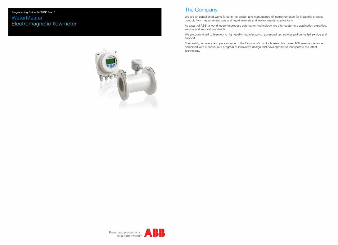
Input/Output (5)
(Inside back cover)
Refer to Instruction Manual IM/WM Refer to: Section 5.2.1, page 14 Refer to: Section 5.2.2, page 16 Refer to Section 5.2.3, page 20
Key:
If the Pulse Mode is set to Fullscale Frequency, the ‘Fullscale Frequency’ screen (6) is displayed instead of the ‘Pulses/Unit’ screen (7)s / Unit' menu is displayed. Displayed only if ‘Device Info’ /
‘Sensor Type’ is ‘Probe’
Advanced AccessStandard Access
WaterMasterElectromagnetic flowmeter
IM/WMP Rev. F 1
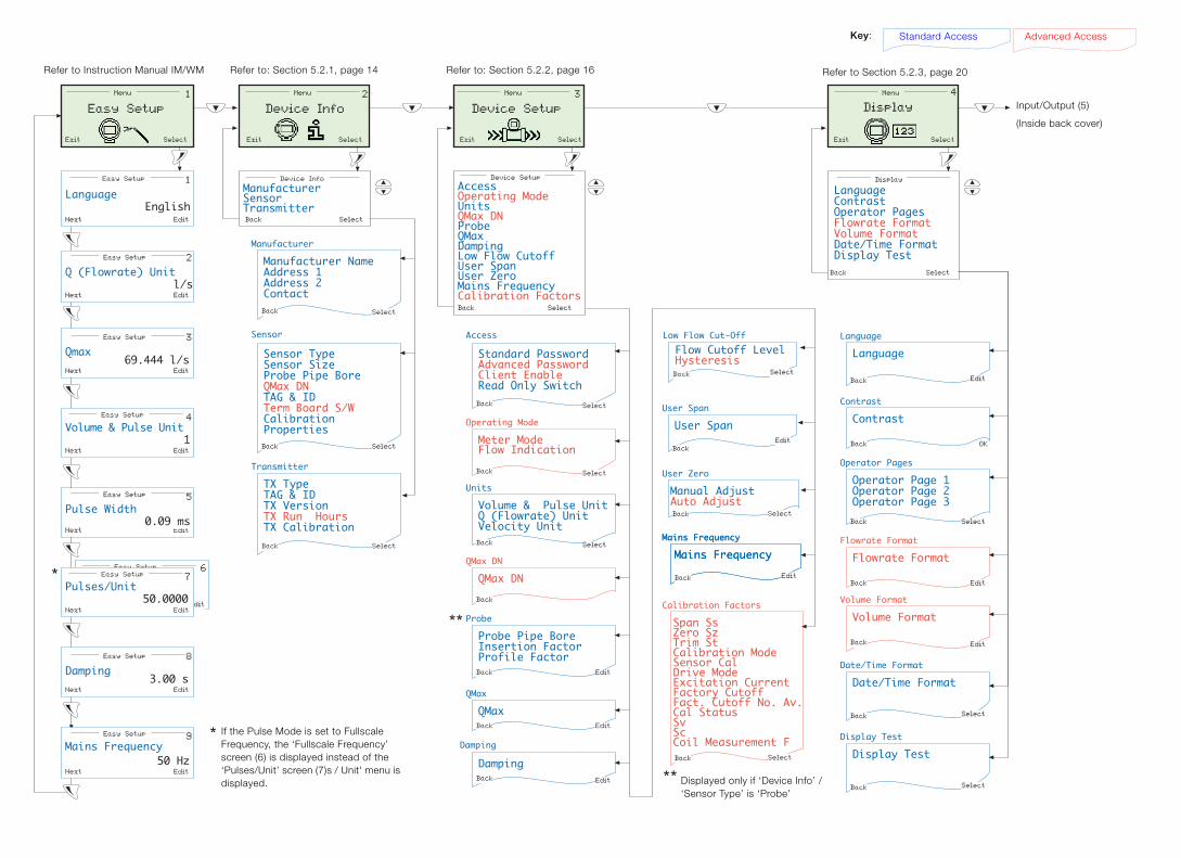
Contents
1 Safety ............................................................................................................................................... 31.1 Electrical Safety ............................................................................................................................................. 31.2 Symbols ........................................................................................................................................................ 31.3 Health & Safety ............................................................................................................................................. 3
2 Introduction ...................................................................................................................................... 42.1 Quality Control .............................................................................................................................................. 4
3 Startup Conditions ........................................................................................................................... 53.1 Data Types ................................................................................................................................................... 53.2 Memory Configuration ................................................................................................................................... 53.3 Alternative Startup Screens ........................................................................................................................... 6
4 Passwords and Security Options .................................................................................................... 84.1 Setting Passwords ........................................................................................................................................ 8
4.1.1 Default Passwords ......................................................................................................................... 84.1.2 Changing Passwords ..................................................................................................................... 8
4.2 Security/Anti-tamper Sealing ......................................................................................................................... 8
5 Overview of Operator Pages and Menus ........................................................................................ 95.1 Operator Menus .......................................................................................................................................... 105.2 Menus ......................................................................................................................................................... 12
5.2.1 Device Info ................................................................................................................................... 145.2.2 Device Setup ................................................................................................................................ 165.2.3 Display ......................................................................................................................................... 205.2.4 Input/Output ................................................................................................................................. 225.2.5 Process Alarm .............................................................................................................................. 255.2.6 Communication ............................................................................................................................ 275.2.7 Totalizer ........................................................................................................................................ 295.2.8 Diagnostics .................................................................................................................................. 305.2.9 Service ......................................................................................................................................... 32
6 HART®-Protocol ............................................................................................................................ 336.1 Overview ..................................................................................................................................................... 336.2 Hardware and Software Requirements ........................................................................................................ 336.3 HART-Protocol Configuration ...................................................................................................................... 346.4 HART-Protocol Connection ......................................................................................................................... 346.5 HART-specific Device Type Manager (DTM FEX100 HART) ......................................................................... 35
6.5.1 Supported Devices (DTM FEX100 HART) ..................................................................................... 356.5.2 DTM (Driver) Version Record ........................................................................................................ 366.5.3 PC Hardware / Operating System Requirements .......................................................................... 366.5.4 Obtaining the WaterMaster Device DTM ...................................................................................... 366.5.5 Installing the WaterMaster Device DTM ......................................................................................... 366.5.6 Updating the WaterMaster Device DTM ........................................................................................ 366.5.7 Getting Help and Further Information ........................................................................................... 366.5.8 Uninstalling the WaterMaster DTM ................................................................................................ 37
WaterMasterElectromagnetic flowmeter
2 IM/WMP Rev. F
7 Troubleshooting .............................................................................................................................387.1 Alarms ........................................................................................................................................................ 38
7.1.1 Alarm Codes ................................................................................................................................. 39
8 Remote Computer Connection .....................................................................................................488.1 Utility Software for PC ................................................................................................................................. 488.2 Installing the Utility Software ........................................................................................................................ 498.3 Attaching the Service Port Adaptor to the Transmitter ................................................................................. 508.4 Configuring the Service Port Splitter ............................................................................................................ 51
8.4.1 Configuration Overview ................................................................................................................. 518.4.2 COM Port and Client Configuration ............................................................................................... 528.4.3 Stopping the Service ................................................................................................................... 558.4.4 Starting the Service ...................................................................................................................... 55
8.5 Cyclic Data Out ........................................................................................................................................... 568.6 Parameter Dump ......................................................................................................................................... 578.7 Remote HMI ................................................................................................................................................ 588.8 HART Client ................................................................................................................................................ 59
Notes .....................................................................................................................................................60

WaterMasterElectromagnetic flowmeter 1 Safety
IM/WMP Rev. F 3
1 SafetyInformation in this manual is intended only to assist our customers in the efficient operation of ourequipment. Use of this manual for any other purpose is specifically prohibited and its contents are not to bereproduced in full or part without prior approval of the Technical Publications Department.
1.1 Electrical SafetyThis equipment complies with the requirements of CEI/IEC 61010-1:2001-2 'Safety Requirements forElectrical Equipment for Measurement, Control and Laboratory Use' and complies with US NEC 500, NISTand OSHA.
If the equipment is used in a manner NOT specified by the Company, the protection provided by theequipment may be impaired.
1.2 SymbolsOne or more of the following symbols may appear on the equipment labelling:
1.3 Health & Safety
Warning – Refer to the manual for instructions Direct current supply only
Caution – Risk of electric shock Alternating current supply only
Protective earth (ground) terminal Both direct and alternating current supply
Earth (ground) terminal The equipment is protected through double insulation
Health and Safety
To ensure that our products are safe and without risk to health, the following points must be noted:
The relevant sections of these instructions must be read carefully before proceeding.
Warning labels on containers and packages must be observed.
Installation, operation, maintenance and servicing must only be carried out by suitably trained personnel and in accordance with the information given.
Normal safety precautions must be taken to avoid the possibility of an accident occurring when operating in conditions of high pressure and/or temperature.
Chemicals must be stored away from heat, protected from temperature extremes and powders kept dry. Normal safe handling procedures must be used.
When disposing of chemicals ensure that no two chemicals are mixed.
Safety advice concerning the use of the equipment described in this manual or any relevant hazard data sheets (where applicable) may be obtained from the Company address on the back cover, together with servicing and spares information.
WaterMasterElectromagnetic flowmeter 2 Introduction
4 IM/WMP Rev. F
2 IntroductionWaterMaster™ is a range of high performance electromagnetic flowmeters for the measurement ofelectrically conductive fluids and systems are normally supplied factory-configured and calibrated.
This Programming Guide provides user details of the WaterMaster transmitter software for 'Read Only','Standard' and 'Advanced' level users.
This guide applies to Application Software V01.02.00 onwards. The version number is found at the menulocation: 'Device Info / Transmitter / TX Version / Application' – see Section 5.2.1, page 14.
This Programming Guide should be used in conjunction with the following publications:
User Guide – IM/WM
User Guide Supplement, PROFIBUS RS485 Physical Layer (FEX100-DP) – IM/WMPBS–EN
User Guide Supplement, PROFIBUS FEX100-DP Parameter Tables – IM/WMPBST–EN
2.1 Quality ControlThe UKAS Calibration Laboratory No. 0255 is just one of the ten flow calibration plants operated by theCompany and is indicative of our dedication to quality and accuracy.
Warning.
System configuration must be carried out only by users or personnel with approved access rights(user privileges).
Read all relevant sections of this guide before configuring the system or modifying systemparameters.
Install and use this equipment as detailed in the Instruction Manual (IM/WM). Install and useassociated equipment in accordance with the relevant national and local standards.
Fig. 2.1 UKAS Calibration Laboratory No. 0255
����
WaterMasterElectromagnetic flowmeter 3 Startup Conditions
IM/WMP Rev. F 5
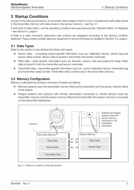
3 Startup ConditionsAs part of the startup procedure, an automatic data integrity check is run to compare and verify data storedin the transmitter memory with data stored in the sensor memory – see Fig. 3.1.
If both sets of data match, normal operating conditions are assumed and the 'Operator Menu' is displayed– see Section 5, page 9.
If there is a data mismatch, alternative user screens are displayed according to the startup conditiondetected. These screens enable data and equipment to be synchronized as detailed in Section 3.3, page 6.
3.1 Data TypesData for the system is sub-divided into three main types:
Sensor data – comprising sensor-specific information such as: calibration factors, sensor tag andsensor serial number. Sensor data is stored in transmitter and sensor memories.
Plant data – plant-specific information such as: flowrate, volume units and pulse/unit range. Plantdata is stored in both the transmitter and sensor memories.
Transmitter data – transmitter-specific information such as: current calibration factors, transmitter tagand transmitter serial number. Transmitter data is stored only in the transmitter memory.
3.2 Memory ConfigurationMemory is allocated according to the type of system as follows:
Remote systems have the transmitter memory fitted at the transmitter and the sensor memory fittedat the sensor.
Integral systems and systems with remote transmitters connected to retrofit sensors have thetransmitter memory and the sensor memory fitted at the transmitter (the sensor memory is mountedon the transmitter backplane).
Fig. 3.1 Memory Location on Remote System
Plant Data Plant Data
Sensor Data
Transmitter Data
Transmitter Memory Sensor Memory
Retrofit and integral systems have the sensor memory mounted on the transmitter backplane
Power In
Sensor Data
WaterMasterElectromagnetic flowmeter 3 Startup Conditions
6 IM/WMP Rev. F
3.3 Alternative Startup Screens
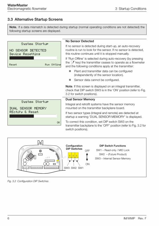
Note. If a data mismatch is detected during startup (normal operating conditions are not detected) thefollowing startup screens are displayed.
No Sensor Detected
If no sensor is detected during start-up, an auto-recovery routine is run to look for the sensor. If no sensor is detected, this routine continues until it is stopped manually.
If 'Run Offline' is selected during auto-recovery (by pressing the key) the transmitter ceases to operate as a flowmeter and the following conditions apply at the transmitter:
Plant and transmitter data can be configured (independently of the sensor location).
Sensor data cannot be configured.
Note. If this screen is displayed on an integral transmitter, check that DIP switch SW3 is in the 'ON' position (refer to Fig. 3.2 for switch positions).
Dual Sensor Memory
Integral and retrofit systems have the sensor memory mounted on the transmitter backplane board.
If two sensor types (integral and remote) are detected at startup a warning 'DUAL SENSOR MEMORY' is displayed.
To correct this condition, set DIP switch SW3 on the transmitter backplane to the 'OFF' position (refer to Fig. 3.2 for switch positions).
Fig. 3.2 Configuration DIP Switches
System Startup
NO SENSOR DETECTEDDevice Resetting
Reset Run Offline
System Startup
DUAL SENSOR MEMORYREctify & Reset
OK
ConfigurationDIP Switches
SW3 SW2 SW1
OFF
ON
SW1 – Read-only / MID Lock
SW2 – (Future Product)
SW3 – Internal Sensor Memory
DIP Switch Functions
WaterMasterElectromagnetic flowmeter 3 Startup Conditions
IM/WMP Rev. F 7
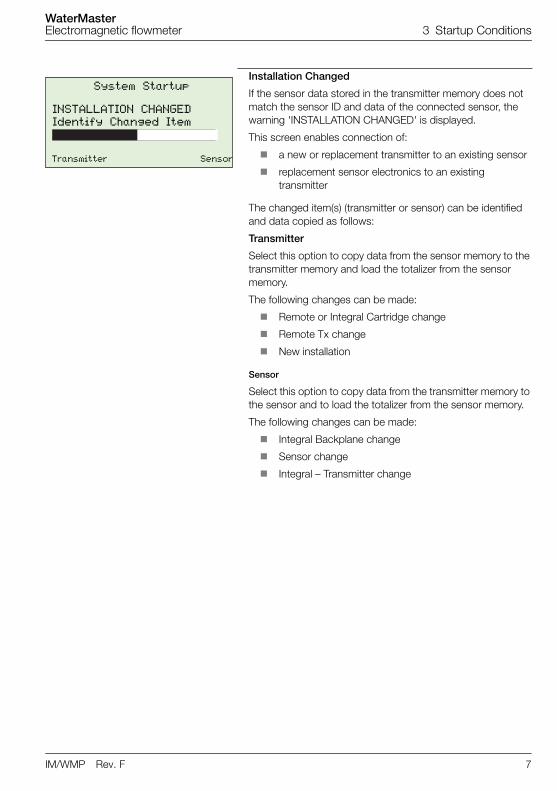
Installation Changed
If the sensor data stored in the transmitter memory does not match the sensor ID and data of the connected sensor, the warning 'INSTALLATION CHANGED' is displayed.
This screen enables connection of:
a new or replacement transmitter to an existing sensor
replacement sensor electronics to an existing transmitter
The changed item(s) (transmitter or sensor) can be identified and data copied as follows:
Transmitter
Select this option to copy data from the sensor memory to the transmitter memory and load the totalizer from the sensor memory.
The following changes can be made:
Remote or Integral Cartridge change
Remote Tx change
New installation
Sensor
Select this option to copy data from the transmitter memory to the sensor and to load the totalizer from the sensor memory.
The following changes can be made:
Integral Backplane change
Sensor change
Integral – Transmitter change
System Startup
INSTALLATION CHANGEDIdentify Changed Item
Transmitter Sensor
WaterMasterElectromagnetic flowmeter 4 Passwords and Security Options
8 IM/WMP Rev. F
4 Passwords and Security OptionsPassword protection can be set to enable access at two levels; 'Standard' and Advanced'. Full end-userconfiguration is possible only by users that log on at the 'Advanced' level.
Passwords at both 'Standard' and 'Advanced' levels can be reset by 'Advanced' level users, but theexisting password must be known before it can be changed. 'Standard' level passwords can be reset onlyby users with 'Standard' level access privileges.
4.1 Setting Passwords
4.1.1 Default PasswordsThe WaterMaster transmitter is supplied with default passwords for access to 'Standard' and 'Advanced'level menus.
The two passwords are:
'Standard' access password: 2 or blank
'Advanced' access password: 3 or blank
Passwords can contain up to 5 characters and are not case sensitive.
To prevent unauthorized access ABB recommend the default passwords are changed on commissioning.
4.1.2 Changing PasswordsPasswords are changed at the 'Device Setup'/'Access' level – see Section 5.2.2, page 16 for details.
4.2 Security/Anti-tamper SealingFor MID compliant flowmeter / additional security, set the Read Only / MID Lock protection switch to 'ON'to ensure the meter is secure from tampering – see Fig. 3.2 on page 6. This switch option can be used inconjunction with physical anti-tamper security seals to provide maximum protection.
For HART software versions prior to 01.02.xx this switch prevents login via the keypad or bus at anysecurity level. For HART software versions prior to 01.03.xx onwards and all PROFIBUS versions, on MIDmeters, all metrological-related parameters are locked and inaccessible at 'Service' level. 'Standard' and'Advanced' level parameters can still be modified via the HMI or bus.
Refer to Instruction Manual (IM/WM) for anti-tamper seal locations.
Note. There is no limit to the number of times a user can attempt to enter an incorrect password.
Note. Once the passwords have been set, the read/write permissions are as follows:
Access at the 'Read Only' level enables a reduced set of read-only parameters to be displayed –no password is required to access these parameters.
Access at the 'Standard' level enables a set of standard read and write parameters to bedisplayed.
Access at the 'Advanced' level enables all available end-user read/write parameters to bedisplayed.
Note. When allocating passwords, record a copy of each password and store in a safe location. It is notpossible to interrogate the transmitter to 'recover' passwords once they have been set.
WaterMasterElectromagnetic flowmeter 5 Overview of Operator Pages and Menus
IM/WMP Rev. F 9
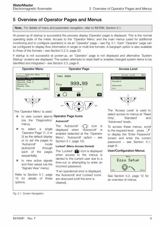
5 Overview of Operator Pages and Menus
At power-up (if startup is successful) the process display (Operator page) is displayed. This is the normaloperating state of the meter. Access to the 'Operator Menu' and the main menus (used for additionalmonitoring and to configure operation) is via an 'Operator' page – see Fig. 5.1. Each 'Operator' page canbe configured to display flow information in single or multi-line formats. A bargraph option is also availableto three of the formats – see Section 5.2.3, page 20.
If startup is not successful at power-up, an 'Operator' page is not displayed and alternative 'SystemStartup' screens are displayed. The system attempts to reset itself or enables changed system items to beidentified and integrated – see Section 3.3, page 6.
Note. For details of menu and parameter navigation, refer to IM/WM, Section 5.1.
Operator Menu
The 'Operator Menu' is used:
to view current alarms(via the 'Diagnostics'menu),
to select a single'Operator Page' (1, 2 or3) as the default displayor to set the pages to'Autoscroll' mode(autoscroll througheach of the pagessequentially,
to view active signalsand their values (via the'Signals View' menu).
Refer to Section 5.1, page10 for details of theseoptions.
Operator Page Access Level
The 'Access Level' is used toselect access to menus at 'ReadOnly', 'Standard' and'Advanced' levels.
To access these menus, scrollto the required level, press to display the 'Enter Password'screen and enter the correctpassword – see Section 4.1,page 8.
User/Configuration Menus
See Section 5.2, page 12 foran overview of menus.
Operator Page Icons
Autoscroll*
The 'Autoscroll' ( ) icon isdisplayed when 'Autoscroll' isenabled (selected at the 'OperatorMenu', 'Autoscroll' option – seeSection 5.1, page 10).
Locked* (Menu Access Denied)
The 'Locked' ( ) icon is displayedwhen access to the menus isdenied to the current user due to atime-out or attempting to enter anincorrect password.
*If an operational error is displayed, the 'Autoscroll' and 'Locked' icons are obscured (until the error is cleared).
Fig. 5.1 Screen Navigation
�Operator MenuDiagnosticsOperator Page 1
Operator Page 2Operator Page 3AutoscrollSignals View
Back Select
TAG: DD04
999.99Flow ml/s
Access Level
Read Only
Standard
Advanced
Back Select
�Menu
Exit Select
Easy Setup
WaterMasterElectromagnetic flowmeter 5 Overview of Operator Pages and Menus
10 IM/WMP Rev. F
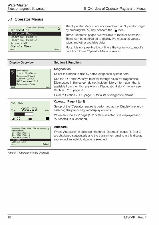
5.1 Operator Menus
The 'Operator Menus' are accessed from an 'Operator Page' by pressing the key beneath the icon.
Three 'Operator' pages are available to monitor operation. These can be configured to display live measured values, totals and other available data.
Note. It is not possible to configure the system or to modify data from these 'Operator Menu' screens.
Display Overview Section & Function
Diagnostics
Select this menu to display active diagnostic system data.
Use the and keys to scroll through all active diagnostics. Diagnostics in this screen do not include history information that is available from the 'Process Alarm'/'Diagnostic History' menu – see Section 5.2.5, page 25.
Refer to Section 7.1.1, page 39 for a list of diagnostic alarms.
Operator Page 1 (to 3)
Setup of the 'Operator' pages is performed at the 'Display' menu by selecting the pre-configured display options.
When an 'Operator' page (1, 2 or 3) is selected, it is displayed and 'Autoscroll' is suspended.
Autoscroll
When 'Autoscroll' is selected, the three 'Operator' pages (1, 2 or 3) are displayed sequentially and the transmitter remains in this display mode until an individual page is selected.
Table 5.1 Operator Menus Overview
�Operator Menu
Back Select
Diagnostics
Operator Page 1
Operator Page 2Operator Page 3AutoscrollSignals View
Operation
–– C178.000 ––
Simulated/Fixed
Current Output
HART Address>0 ?
Simulation Mode
Back Exit
Flow ml/s
TAG: DD04
999.99
Operator MenuDiagnostics
Operator Page 1Operator Page 2
Operator Page 3
AutoscrollSignals View
Back Select
WaterMasterElectromagnetic flowmeter 5 Overview of Operator Pages and Menus
IM/WMP Rev. F 11
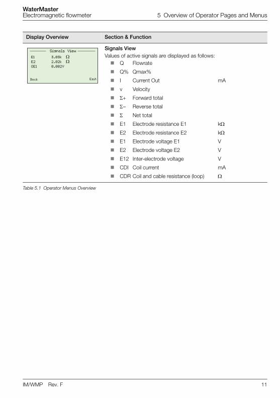
Signals ViewValues of active signals are displayed as follows: Q Flowrate
Q% Qmax%
I Current Out mA
v Velocity
Forward total
– Reverse total
Net total
E1 Electrode resistance E1 k
E2 Electrode resistance E2 k
E1 Electrode voltage E1 V
E2 Electrode voltage E2 V
E12 Inter-electrode voltage V
CDI Coil current mA
CDR Coil and cable resistance (loop)
Display Overview Section & Function
Table 5.1 Operator Menus Overview
Signals View
E1 3.03k E2 2.02k OE1 0.002V
Back Exit
WaterMasterElectromagnetic flowmeter 5 Overview of Operator Pages and Menus
12 IM/WMP Rev. F
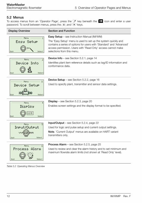
5.2 MenusTo access menus from an 'Operator Page', press the key beneath the icon and enter a userpassword. To scroll between menus, press the and keys.
Display Overview Section and Function
Easy Setup – see Instruction Manual (IM/WM)
The 'Easy Setup' menu is used to set up the system quickly and contains a series of options for users with 'Standard' and 'Advanced' access permission. Users with 'Read Only' access cannot make selections from this menu.
Device Info – see Section 5.2.1, page 14
Identifies plant item reference details such as tag/ID information and conformance data.
Device Setup – see Section 5.2.2, page 16
Used to specify plant, transmitter and sensor data settings.
Display – see Section 5.2.3, page 20
Enables screen settings and the display format to be specified.
Input/Output – see Section 5.2.4, page 22
Used for logic and pulse setup and current output settings.
Note. 'Current Output' menus are available on HART variant transmitters only.
Process Alarm – see Section 5.2.5, page 25
Used to review and clear the alarm history and to set minimum and maximum flowrate alarm limits (not shown at 'Read Only' level).
Table 5.2 Operating Menus Overview
�Menu
Exit Select
Easy Setup
�Menu
Exit Select
Device Info
�Menu
Exit Select
Device Setup
Menu
Exit Select
Display
!Menu
Exit Select
Input/Output
%Menu
Exit Select
Process Alarm
WaterMasterElectromagnetic flowmeter 5 Overview of Operator Pages and Menus
IM/WMP Rev. F 13
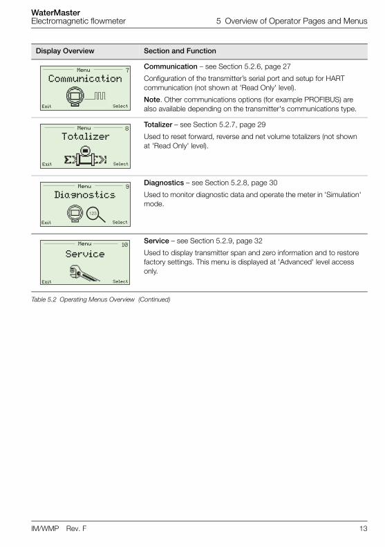
Communication – see Section 5.2.6, page 27
Configuration of the transmitter’s serial port and setup for HART communication (not shown at 'Read Only' level).
Note. Other communications options (for example PROFIBUS) are also available depending on the transmitter's communications type.
Totalizer – see Section 5.2.7, page 29
Used to reset forward, reverse and net volume totalizers (not shown at 'Read Only' level).
Diagnostics – see Section 5.2.8, page 30
Used to monitor diagnostic data and operate the meter in 'Simulation' mode.
Service – see Section 5.2.9, page 32
Used to display transmitter span and zero information and to restore factory settings. This menu is displayed at 'Advanced' level access only.
Display Overview Section and Function
Table 5.2 Operating Menus Overview (Continued)
"Menu
Exit Select
Communication
#Menu
Exit Select
Totalizer
$
���
Menu
Exit Select
Diagnostics
�&Menu
Exit Select
Service
WaterMasterElectromagnetic flowmeter 5 Overview of Operator Pages and Menus
14 IM/WMP Rev. F
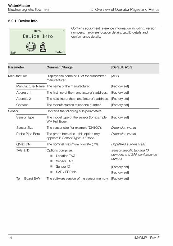
5.2.1 Device Info
Contains equipment reference information including; version numbers, hardware location details, tag/ID details and conformance details.
Parameter Comment/Range [Default] Note
Manufacturer Displays the name or ID of the transmitter manufacturer.
[ABB]
Manufacturer Name The name of the manufacturer. [Factory set]
Address 1 The first line of the manufacturer’s address. [Factory set]
Address 2 The next line of the manufacturer’s address. [Factory set]
Contact The manufacturer’s telephone number. [Factory set]
Sensor Contains the following sub-parameters:
Sensor Type The model type of the sensor (for example WM Full Bore).
[Factory set]
Sensor Size The sensor size (for example 'DN100'). Dimension in mm
Probe Pipe Bore The probe bore size – this option only appears if 'Sensor Type' is 'Probe'.
Dimension in mm
QMax DN The nominal maximum flowrate (Q3). Populated automatically
TAG & ID Options comprise:
Location TAG
Sensor TAG
Sensor ID
SAP / ERP No.
Sensor-specific tag and ID numbers and SAP conformance number
[Factory set]
[Factory set]
Term Board S/W The software version of the sensor memory. [Factory set]
�Menu
Exit Select
Device Info
WaterMasterElectromagnetic flowmeter 5 Overview of Operator Pages and Menus
IM/WMP Rev. F 15
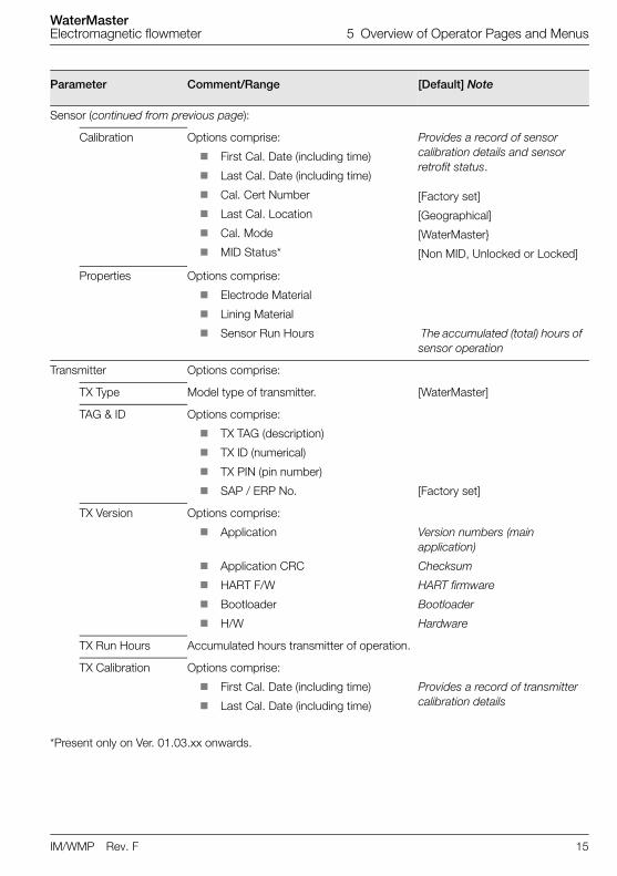
Parameter Comment/Range [Default] Note
Sensor (continued from previous page):
Calibration Options comprise:
First Cal. Date (including time)
Last Cal. Date (including time)
Cal. Cert Number
Last Cal. Location
Cal. Mode
MID Status*
Provides a record of sensor calibration details and sensor retrofit status.
[Factory set]
[Geographical]
[WaterMaster}
[Non MID, Unlocked or Locked]
Properties Options comprise:
Electrode Material
Lining Material
Sensor Run Hours The accumulated (total) hours of sensor operation
Transmitter Options comprise:
TX Type Model type of transmitter. [WaterMaster]
TAG & ID Options comprise:
TX TAG (description)
TX ID (numerical)
TX PIN (pin number)
SAP / ERP No. [Factory set]
TX Version Options comprise:
Application
Application CRC
HART F/W
Bootloader
H/W
Version numbers (main application)
Checksum
HART firmware
Bootloader
Hardware
TX Run Hours Accumulated hours transmitter of operation.
TX Calibration Options comprise:
First Cal. Date (including time)
Last Cal. Date (including time)
Provides a record of transmitter calibration details
*Present only on Ver. 01.03.xx onwards.
WaterMasterElectromagnetic flowmeter 5 Overview of Operator Pages and Menus
16 IM/WMP Rev. F
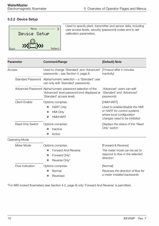
5.2.2 Device Setup
Used to specify plant, transmitter and sensor data, including user access levels, security (password) codes and to set calibration parameters.
Parameter Comment/Range [Default] Note
Access Used to change 'Standard' and 'Advanced' passwords – see Section 4, page 8.
[Timeout after 5 minutes. inactivity]
Standard Password Alpha/numeric selection – a 'Standard' user can only edit 'Standard' passwords.
Advanced Password Alpha/numeric password selection of the 'Advanced' level password (not displayed at 'Standard' access level).
'Advanced' users can edit 'Standard' and 'Advanced' passwords
Client Enable Options comprise:
HART Only
HMI Only
HMI/HART
[HMI/HART]
Used to enable/disable the HMI or HART for control systems where local configuration changes need to be inhibited
Read Only Switch Options comprise:
Inactive
Active
Displays the status of the 'Read Only' switch
Operating Mode
Meter Mode Options comprise:
Forward And Reverse
Forward Only*
Reverse Only*
[Forward & Reverse]
The meter mode can be set to respond to flow in the selected direction
Flow Indication Options comprise:
Normal
Reversed
[Normal]
Reverses the direction of flow for a meter installed backwards
*For MID-locked flowmeters (see Section 4.2, page 8) only 'Forward And Reverse' is permitted.
�Menu
Exit Select
Device Setup
WaterMasterElectromagnetic flowmeter 5 Overview of Operator Pages and Menus
IM/WMP Rev. F 17
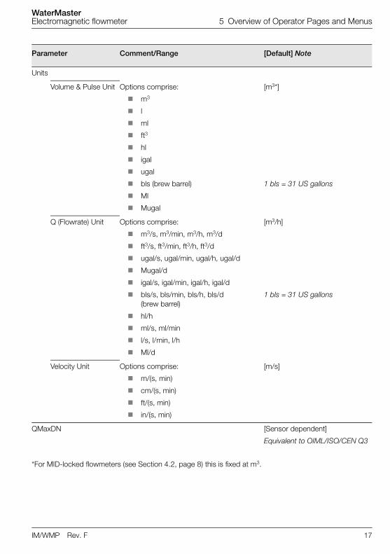
Parameter Comment/Range [Default] Note
Units
Volume & Pulse Unit Options comprise:
m3
l
ml
ft3
hl
igal
ugal
bls (brew barrel)
Ml
Mugal
[m3*]
1 bls = 31 US gallons
Q (Flowrate) Unit Options comprise:
m3/s, m3/min, m3/h, m3/d
ft3/s, ft3/min, ft3/h, ft3/d
ugal/s, ugal/min, ugal/h, ugal/d
Mugal/d
igal/s, igal/min, igal/h, igal/d
bls/s, bls/min, bls/h, bls/d (brew barrel)
hl/h
ml/s, ml/min
l/s, l/min, l/h
Ml/d
[m3/h]
1 bls = 31 US gallons
Velocity Unit Options comprise:
m/(s, min)
cm/(s, min)
ft/(s, min)
in/(s, min)
[m/s]
QMaxDN [Sensor dependent]
Equivalent to OIML/ISO/CEN Q3
*For MID-locked flowmeters (see Section 4.2, page 8) this is fixed at m3.
WaterMasterElectromagnetic flowmeter 5 Overview of Operator Pages and Menus
18 IM/WMP Rev. F
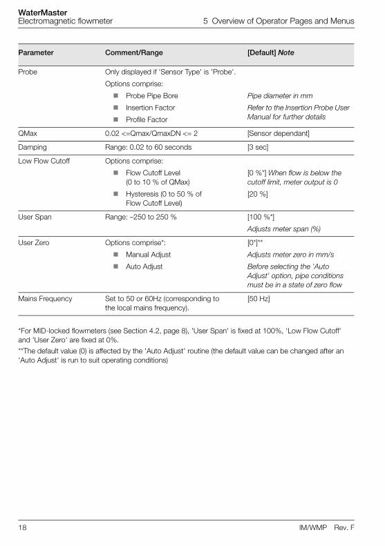
Parameter Comment/Range [Default] Note
Probe Only displayed if 'Sensor Type' is 'Probe'.
Options comprise:
Probe Pipe Bore
Insertion Factor
Profile Factor
Pipe diameter in mm
Refer to the Insertion Probe User Manual for further details
QMax 0.02 <=Qmax/QmaxDN <= 2 [Sensor dependant]
Damping Range: 0.02 to 60 seconds [3 sec]
Low Flow Cutoff Options comprise:
Flow Cutoff Level(0 to 10 % of QMax)
Hysteresis (0 to 50 % of Flow Cutoff Level)
[0 %*] When flow is below the cutoff limit, meter output is 0
[20 %]
User Span Range: –250 to 250 % [100 %*]
Adjusts meter span (%)
User Zero Options comprise*:
Manual Adjust
Auto Adjust
[0*]**
Adjusts meter zero in mm/s
Before selecting the 'Auto Adjust' option, pipe conditions must be in a state of zero flow
Mains Frequency Set to 50 or 60Hz (corresponding to the local mains frequency).
[50 Hz]
*For MID-locked flowmeters (see Section 4.2, page 8), 'User Span' is fixed at 100%, 'Low Flow Cutoff' and 'User Zero' are fixed at 0%.
**The default value (0) is affected by the 'Auto Adjust' routine (the default value can be changed after an 'Auto Adjust' is run to suit operating conditions)
WaterMasterElectromagnetic flowmeter 5 Overview of Operator Pages and Menus
IM/WMP Rev. F 19
Parameter Comment/Range [Default] Note
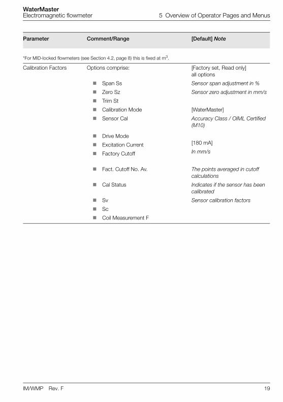
*For MID-locked flowmeters (see Section 4.2, page 8) this is fixed at m3.
Calibration Factors Options comprise:
Span Ss
Zero Sz
Trim St
Calibration Mode
Sensor Cal
Drive Mode
Excitation Current
Factory Cutoff
Fact. Cutoff No. Av.
Cal Status
Sv
Sc
Coil Measurement F
[Factory set, Read only] all options
Sensor span adjustment in %
Sensor zero adjustment in mm/s
[WaterMaster]
Accuracy Class / OIML Certified (M10)
[180 mA]
In mm/s
The points averaged in cutoff calculations
Indicates if the sensor has been calibrated
Sensor calibration factors
WaterMasterElectromagnetic flowmeter 5 Overview of Operator Pages and Menus
20 IM/WMP Rev. F
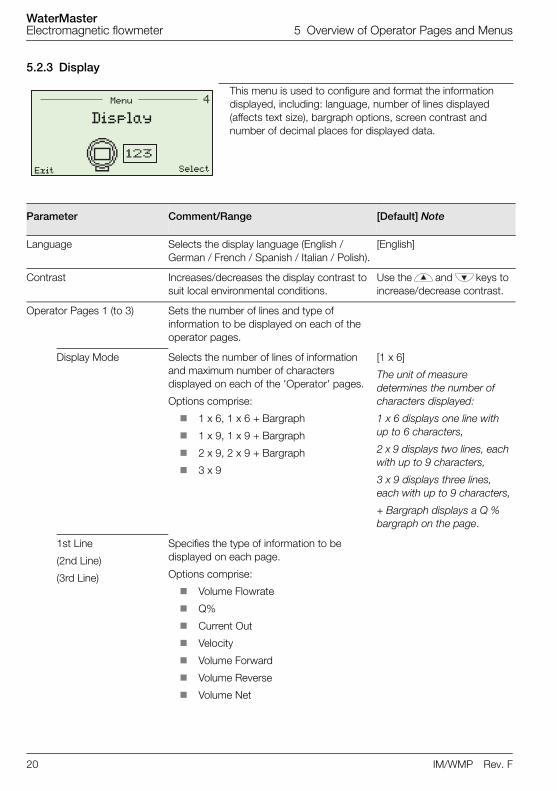
5.2.3 Display
This menu is used to configure and format the information displayed, including: language, number of lines displayed (affects text size), bargraph options, screen contrast and number of decimal places for displayed data.
Parameter Comment/Range [Default] Note
Language Selects the display language (English / German / French / Spanish / Italian / Polish).
[English]
Contrast Increases/decreases the display contrast to suit local environmental conditions.
Use the and keys to increase/decrease contrast.
Operator Pages 1 (to 3) Sets the number of lines and type of information to be displayed on each of the operator pages.
Display Mode Selects the number of lines of information and maximum number of characters displayed on each of the 'Operator' pages.
Options comprise:
1 x 6, 1 x 6 + Bargraph
1 x 9, 1 x 9 + Bargraph
2 x 9, 2 x 9 + Bargraph
3 x 9
[1 x 6]
The unit of measure determines the number of characters displayed:
1 x 6 displays one line with up to 6 characters,
2 x 9 displays two lines, each with up to 9 characters,
3 x 9 displays three lines, each with up to 9 characters,
+ Bargraph displays a Q % bargraph on the page.
1st Line
(2nd Line)
(3rd Line)
Specifies the type of information to be displayed on each page.
Options comprise:
Volume Flowrate
Q%
Current Out
Velocity
Volume Forward
Volume Reverse
Volume Net
Menu
Exit Select
Display
WaterMasterElectromagnetic flowmeter 5 Overview of Operator Pages and Menus
IM/WMP Rev. F 21
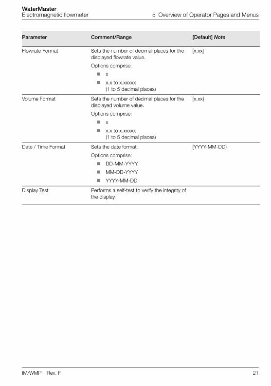
Parameter Comment/Range [Default] Note
Flowrate Format Sets the number of decimal places for the displayed flowrate value.
Options comprise:
x
x.x to x.xxxxx (1 to 5 decimal places)
[x.xx]
Volume Format Sets the number of decimal places for the displayed volume value.
Options comprise:
x
x.x to x.xxxxx (1 to 5 decimal places)
[x.xx}
Date / Time Format Sets the date format.
Options comprise:
DD-MM-YYYY
MM-DD-YYYY
YYYY-MM-DD
[YYYY-MM-DD}
Display Test Performs a self-test to verify the integrity of the display.
WaterMasterElectromagnetic flowmeter 5 Overview of Operator Pages and Menus
22 IM/WMP Rev. F
5.2.4 Input/Output
This menu is used to setup logic states, pulse states and current output settings.
Note. 'Current Output' menus are available on HART-variant transmitters only.
Parameter Comment/Range [Default] Note
Output Readings Displays current output and pulse values. 'Current Output' menus are available on HART-variant transmitters only.
Current [mA]
D01 Pulses (or)
D01 State
Pulse output frequency (only one option is displayed).
[Hz] Context dependent, depending on 'DO1/DO2 Function' setting
D02 Pulses (or)
D02 State
Logic output state – open/closed (only one option is displayed).
[Open] Context dependent
D03 State High/Low output state (open/closed). DO3 is Logic Out only
Output Setup Configures the function of digital outputs DO1 and DO2.
Logic/pulse options selected at this menu determine options displayed at the 'Output Reading' and ’Logic Setup’ menus
D01/D02 Function Options comprise:
Pulse F/Pulse R
Pulse F/Logic
Pulse FR/Logic
Logic/Logic
[Pulse FR/Logic]
Forward/reverse pulse
Forward pulse/logic output
Pulse forward/reverse/logic
Logic Setup Configures the function of the logic outputs.
If DO1 = Logic, the DO1 menu is displayed
If DO2 = Logic, the DO2 menu is displayed
DO1 Logic
DO2 Logic
D03 Logic
Options comprise:
No Function
F/R Signal (forward/reverse)
Digital Out Alarm
[No Function]
!Menu
Exit Select
Input/Output
WaterMasterElectromagnetic flowmeter 5 Overview of Operator Pages and Menus
IM/WMP Rev. F 23
Parameter Comment/Range [Default] Note
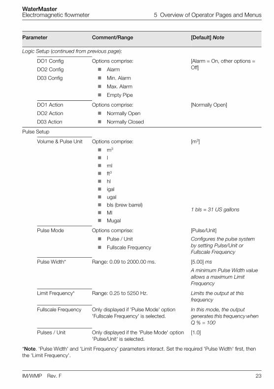
Logic Setup (continued from previous page):
DO1 Config
DO2 Config
D03 Config
Options comprise:
Alarm
Min. Alarm
Max. Alarm
Empty Pipe
[Alarm = On, other options = Off]
DO1 Action
DO2 Action
D03 Action
Options comprise:
Normally Open
Normally Closed
[Normally Open]
Pulse Setup
Volume & Pulse Unit Options comprise:
m3
l
ml
ft3
hl
igal
ugal
bls (brew barrel)
Ml
Mugal
[m3]
1 bls = 31 US gallons
Pulse Mode Options comprise:
Pulse / Unit
Fullscale Frequency
[Pulse/Unit]
Configures the pulse system by setting Pulse/Unit or Fullscale Frequency
Pulse Width* Range: 0.09 to 2000.00 ms. [5.00] ms
A minimum Pulse Width value allows a maximum Limit Frequency
Limit Frequency* Range: 0.25 to 5250 Hz. Limits the output at this frequency
Fullscale Frequency Only displayed if 'Pulse Mode' option 'Fullscale Frequency' is selected.
In this mode, the output generates this frequency when Q % = 100
Pulses / Unit Only displayed if the 'Pulse Mode' option 'Pulse/Unit' is selected.
[1.0]
*Note. 'Pulse Width' and 'Limit Frequency' parameters interact. Set the required 'Pulse Width' first, then the 'Limit Frequency'.
WaterMasterElectromagnetic flowmeter 5 Overview of Operator Pages and Menus
24 IM/WMP Rev. F
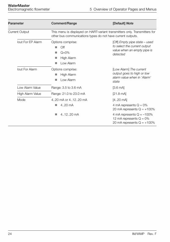
Parameter Comment/Range [Default] Note
Current Output This menu is displayed on HART-variant transmitters only. Transmitters forother bus communications types do not have current outputs.
Iout For EP Alarm Options comprise:
Off
Q=0%
High Alarm
Low Alarm
[Off] Empty pipe state – used to select the current output value when an empty pipe is detected
Iout For Alarm Options comprise:
High Alarm
Low Alarm
[Low Alarm] The current output goes to high or low alarm value when in 'Alarm' state
Low Alarm Value Range: 3.5 to 3.6 mA [3.6 mA]
High Alarm Value Range: 21.0 to 23.0 mA [21.8 mA]
Mode 4..20 mA or 4..12..20 mA
4..20 mA
4..12..20 mA
[4..20 mA]
4 mA represents Q = 0%20 mA represents Q = +100%
4 mA represents Q = –100%12 mA represents Q = 0%20 mA represents Q = +100%
WaterMasterElectromagnetic flowmeter 5 Overview of Operator Pages and Menus
IM/WMP Rev. F 25
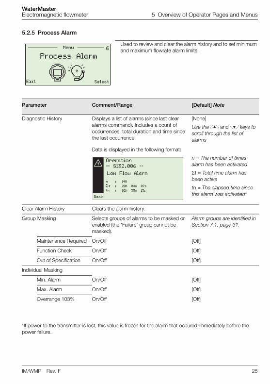
5.2.5 Process Alarm
Used to review and clear the alarm history and to set minimum and maximum flowrate alarm limits.
Parameter Comment/Range [Default] Note
Diagnostic History Displays a list of alarms (since last clear alarms command). Includes a count of occurrences, total duration and time since the last occurrence.
[None]
Use the and keys to scroll through the list of alarms
Data is displayed in the following format:
n = The number of times alarm has been activated
t = Total time alarm has been active
tn = The elapsed time since this alarm was activated*
Clear Alarm History Clears the alarm history.
Group Masking Selects groups of alarms to be masked or enabled (the 'Failure' group cannot be masked).
Alarm groups are identified in Section 7.1, page 31.
Maintenance Required On/Off [Off]
Function Check On/Off [Off]
Out of Specification On/Off [Off]
Individual Masking
Min. Alarm On/Off [Off]
Max. Alarm On/Off [Off]
Overrange 103% On/Off [Off]
*If power to the transmitter is lost, this value is frozen for the alarm that occured immediately before the power failure.
%Menu
Exit Select
Process Alarm
Operation
–– S132.006 ––
Low Flow Alarm
Back
n : 148
: 20h 04m 07s
tn : 02h 53m 15s
WaterMasterElectromagnetic flowmeter 5 Overview of Operator Pages and Menus
26 IM/WMP Rev. F
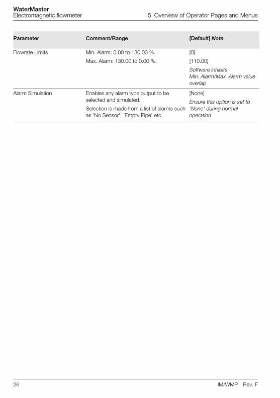
Parameter Comment/Range [Default] Note
Flowrate Limits Min. Alarm: 0.00 to 130.00 %.
Max. Alarm: 130.00 to 0.00 %.
[0]
[110.00]
Software inhibits Min. Alarm/Max. Alarm value overlap
Alarm Simulation Enables any alarm type output to be selected and simulated.
Selection is made from a list of alarms such as 'No Sensor', 'Empty Pipe' etc.
[None]
Ensure this option is set to 'None' during normal operation
WaterMasterElectromagnetic flowmeter 5 Overview of Operator Pages and Menus
IM/WMP Rev. F 27
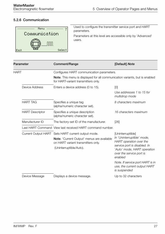
5.2.6 Communication
Used to configure the transmitter service port and HART parameters.
Parameters at this level are accessible only by 'Advanced' users.
Parameter Comment/Range [Default] Note
HART Configures HART communication parameters.
Note. This menu is displayed for all communication variants, but is enabled for HART-variant transmitters only.
Device Address Enters a device address (0 to 15). [0]
Use addresses 1 to 15 for multidrop mode
HART TAG Specifies a unique tag (alpha/numeric character set).
8 characters maximum
HART Descriptor Specifies a unique description (alpha/numeric character set).
16 characters maximum
Manufacturer ID The factory-set ID of the manufacturer. [26]
Last HART Command View last received HART command number.
Current Output HART Sets HART current output mode.
Note. 'Current Output' menus are available on HART variant transmitters only.
(Uninterruptible/Auto).
[Uninterruptible] In 'Uninterruptible' mode, HART operation over the service port is disabled. In 'Auto' mode, HART operation over the service port is enabled
Note. If service port HART is in use, the current output HART is suspended
Device Message Displays a device message. Up to 32 characters
"Menu
Exit Select
Communication
WaterMasterElectromagnetic flowmeter 5 Overview of Operator Pages and Menus
28 IM/WMP Rev. F
Parameter Comment/Range [Default] Note
Cyclic Data Out Displays a regular, updated table of information over the service port.
[1 s] Cyclic data can be output to PC via the (optional) Service Port Splitter/Adaptor – refer to Section 8.5, page 56 to run a Cyclic Data Out routine
Cyclic Update Rate The rate cyclic data is updated (range: 0.2 to 3600.00 s).
Cyclic Update Sel. Each group can be enabled or disabled according to the cyclic data types to be updated and (optionally) output to a PC.
Options comprise:
Flow Group
Outputs Group
Electrodes Group
Status Group
Coil Group
TX Group
Vol. Totals Group
[Disabled]
Service Port Sets the Baud rate.
Max Baud Rate Baud rate options (bps):
2400
4800
9600
19200
38400
[38400 bps]
WaterMasterElectromagnetic flowmeter 5 Overview of Operator Pages and Menus
IM/WMP Rev. F 29
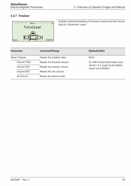
5.2.7 Totalizer
Enables individual resetting of forward, reverse and net volume data by 'Advanced' users.
Parameter Comment/Range [Default] Note
Reset Totalizer Resets the totalizer data. [N/A]
Volume FWD Resets the forward volume For MID-locked flowmeters (see Section 4.2, page 8) all totalizer resets are inhibited.
Volume REV Resets the reverse volume
Volume NET Resets the net volume
All Volume Resets all volume totals
#Menu
Exit Select
Totalizer
WaterMasterElectromagnetic flowmeter 5 Overview of Operator Pages and Menus
30 IM/WMP Rev. F
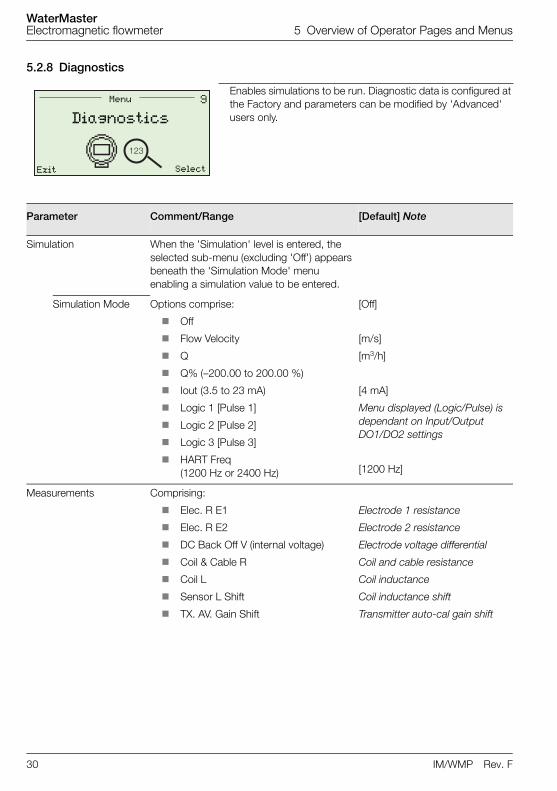
5.2.8 Diagnostics
Enables simulations to be run. Diagnostic data is configured at the Factory and parameters can be modified by 'Advanced' users only.
Parameter Comment/Range [Default] Note
Simulation When the 'Simulation' level is entered, the selected sub-menu (excluding 'Off') appears beneath the 'Simulation Mode' menu enabling a simulation value to be entered.
Simulation Mode Options comprise:
Off
Flow Velocity
Q
Q% (–200.00 to 200.00 %)
Iout (3.5 to 23 mA)
Logic 1 [Pulse 1]
Logic 2 [Pulse 2]
Logic 3 [Pulse 3]
HART Freq (1200 Hz or 2400 Hz)
[Off]
[m/s]
[m3/h]
[4 mA]
Menu displayed (Logic/Pulse) is dependant on Input/Output DO1/DO2 settings
[1200 Hz]
Measurements Comprising:
Elec. R E1
Elec. R E2
DC Back Off V (internal voltage)
Coil & Cable R
Coil L
Sensor L Shift
TX. AV. Gain Shift
Electrode 1 resistance
Electrode 2 resistance
Electrode voltage differential
Coil and cable resistance
Coil inductance
Coil inductance shift
Transmitter auto-cal gain shift
$
���
Menu
Exit Select
Diagnostics
WaterMasterElectromagnetic flowmeter 5 Overview of Operator Pages and Menus
IM/WMP Rev. F 31
Parameter Comment/Range [Default] Note
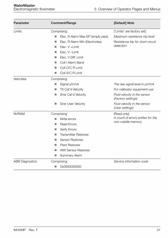
Limits Comprising:
Elec. R Alarm Max EP (empty pipe)
Elec. R Alarm Min (Electrodes)
Elec. V +Limit
Elec. V –Limit
Elec. V Diff. Limit
Coil I Alarm Band
Coil O/C R Limit
Coil S/C R Limit
['Limits' are factory set]
Maximum resistance trip level
Resistance trip for short circuit detection
Velocities Comprising:
Signal µV/mA
TX Cal’d Velocity
Snsr Cal’d Velocity
Snsr User Velocity
The raw signal level in µV/mA
For calibrator equipment use
Fluid velocity in the sensor (Factory settings)
Fluid velocity in the sensor (User settings)
NVRAM Comprising:
Write errors
Read Errors
Verify Errors
Transmitter Restores
Sensor Restores
Plant Restores
WW Sensor Restores
Summary Alarm
[Read only]A count of errors written for the non-volatile memory
ABB Diagnostics Comprising:
0x0000000000
Service information code
WaterMasterElectromagnetic flowmeter 5 Overview of Operator Pages and Menus
32 IM/WMP Rev. F
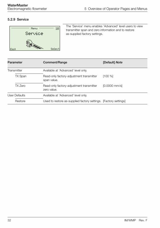
5.2.9 Service
The 'Service' menu enables 'Advanced' level users to view transmitter span and zero information and to restore as-supplied factory settings.
Parameter Comment/Range [Default] Note
Transmitter Available at 'Advanced' level only.
TX Span Read-only factory-adjustment transmitter span value.
[100 %]
TX Zero Read-only factory-adjustment transmitter zero value.
[0.0000 mm/s]
User Defaults Available at 'Advanced' level only.
Restore Used to restore as-supplied factory settings. [Factory settings]
�&Menu
Exit Select
Service
WaterMasterElectromagnetic flowmeter 6 HART®-Protocol
IM/WMP Rev. F 33
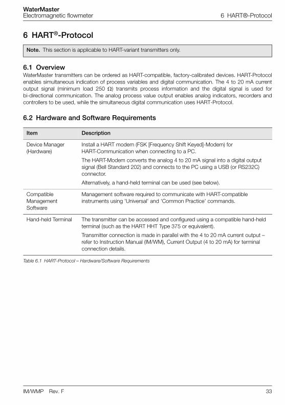
6 HART®-Protocol
6.1 OverviewWaterMaster transmitters can be ordered as HART-compatible, factory-calibrated devices. HART-Protocolenables simultaneous indication of process variables and digital communication. The 4 to 20 mA currentoutput signal (minimum load 250 ) transmits process information and the digital signal is used forbi-directional communication. The analog process value output enables analog indicators, recorders andcontrollers to be used, while the simultaneous digital communication uses HART-Protocol.
6.2 Hardware and Software Requirements
Note. This section is applicable to HART-variant transmitters only.
Item Description
Device Manager (Hardware)
Install a HART modem (FSK [Frequency Shift Keyed]-Modem) for HART-Communication when connecting to a PC.
The HART-Modem converts the analog 4 to 20 mA signal into a digital output signal (Bell Standard 202) and connects to the PC using a USB (or RS232C) connector.
Alternatively, a hand-held terminal can be used (see below).
Compatible Management Software
Management software required to communicate with HART-compatible instruments using 'Universal' and 'Common Practice' commands.
Hand-held Terminal The transmitter can be accessed and configured using a compatible hand-held terminal (such as the HART HHT Type 375 or equivalent).
Transmitter connection is made in parallel with the 4 to 20 mA current output – refer to Instruction Manual (IM/WM), Current Output (4 to 20 mA) for terminal connection details.
Table 6.1 HART-Protocol – Hardware/Software Requirements
WaterMasterElectromagnetic flowmeter 6 HART®-Protocol
34 IM/WMP Rev. F
6.3 HART-Protocol ConfigurationHART-variant WaterMasters are read and configured using Common Practice and Universal commands forthe following parameters:
Q
QMax (PV, URV)
Damping
Iout
Loop Test (4 to 20 mA)
HART Descriptor
HART Tag
HART Device Message
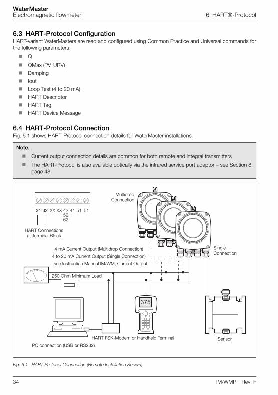
6.4 HART-Protocol ConnectionFig. 6.1 shows HART-Protocol connection details for WaterMaster installations.
Note.
Current output connection details are common for both remote and integral transmitters
The HART-Protocol is also available optically via the infrared service port adaptor – see Section 8,page 48
Fig. 6.1 HART-Protocol Connection (Remote Installation Shown)
���
�� �� �� �� ������
�� �� ��
HART FSK-Modem or Handheld Terminal
4 mA Current Output (Multidrop Connection)
4 to 20 mA Current Output (Single Connection)
– see Instruction Manual IM/WM, Current Output
PC connection (USB or RS232)
MultidropConnection
Sensor
250 Ohm Minimum Load
Single Connection
HART Connections at Terminal Block
WaterMasterElectromagnetic flowmeter 6 HART®-Protocol
IM/WMP Rev. F 35
6.5 HART-specific Device Type Manager (DTM FEX100 HART)
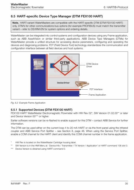
WaterMaster can be integrated into control systems and configuration devices using any Frame application,such as ABB AssetVision or similar third-party applications. ABB Device Type Managers (DTMs) forWaterMaster provide a unified structure for accessing device parameters, configuring and operating thedevices and diagnosing problems. FDT (Field Device Tool) technology standardizes the communication andconfiguration interface between all field devices and host systems.
6.5.1 Supported Devices (DTM FEX100 HART)FEX100 HART WaterMaster Electromagnetic Flowmeter with HW Rev 02*, SW Version 01.02.00** or laterand Device Version 00*** or higher.
Earlier software versions can be re-flashed to enable support for this DTM – contact ABB Service for furtherinformation.
The DTM can be used either on the current loop 4 to 20 mA HART or via the front panel using the infraredcoupler and ABB Service Port Splitter – see Section 8, page 48. When using the Service Port Splitter,enable a COM channel for the HART client and identify this COM channel number in the frame application.
* HW Rev is located on the WaterMaster Cartridge housing label.** SW Version is in the HMI Menu at 'Device Info / Transmitter / TX Version / Application' or HART command 136 slot 0.*** Device Version is obtained using HART command 0.
Note. HART-variant WaterMasters are compatible with the HART-specific DTM (DTM FEX100 HART) only. DTM’s for other communications bus options (for example PROFIBUS) must match the transmitter variant – refer to DS/WM-EN for system options and ordering details.
Fig. 6.2 Example Frame Application
DTM Device Driver
FDT Interface
Frame Application
WaterMasterElectromagnetic flowmeter 6 HART®-Protocol
36 IM/WMP Rev. F
6.5.2 DTM (Driver) Version Record The Device DTM should be usable in all frame applications meeting the requirements of FDT 1.2/1.2.1.
6.5.3 PC Hardware / Operating System RequirementsThe following hardware / software is required:
Processor – Intel compatible (2GHz)
512 Mb RAM
Windows 2000 SP4 / XP SP2 or SP3 / VISTA
Microsoft .NET Framework 2.0
Microsoft Internet Explorer 6.0 or a similar internet browser
6.5.4 Obtaining the WaterMaster Device DTM Download the WaterMaster Device DTM from the ABB website:
http://www.abb.com/product/seitp330/43036b0a80621b48c12573de003d803a.aspx
6.5.5 Installing the WaterMaster Device DTMTo install the WaterMaster DTM Device Driver:
1. Close all FDT applications.
2. Unzip the WaterMaster Device DTM zip file and run 'Setup.exe' from the main folder.
3. Follow the on-screen prompts to complete the installation.
6.5.6 Updating the WaterMaster Device DTMNewer versions of the WaterMaster Device DTM can be installed over older versions. To revert to an olderversion, uninstall the existing (newer) installation before installing the older version.
6.5.7 Getting Help and Further Information Press F1 on the WaterMaster Device DTM window activates the online help system.
Help relating to the integration of the WaterMaster Device DTM in the FDT frame application is within therespective documentation of the frame application.
Released Driver Version
Release Date Release Bundle / Library
Remarks
05.00.00 Oct. 2009 05.00.05/05.00.12 Initial release
Table 6.2 DTM (Driver) Version Record
WaterMasterElectromagnetic flowmeter 6 HART®-Protocol
IM/WMP Rev. F 37
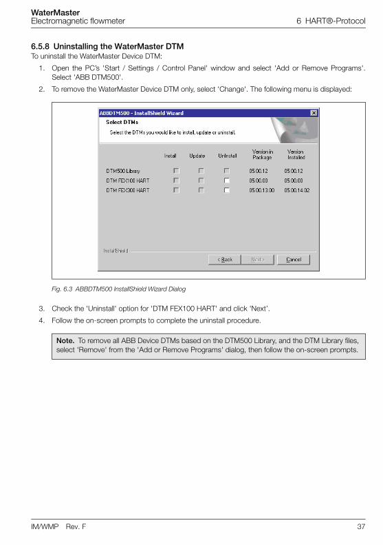
6.5.8 Uninstalling the WaterMaster DTMTo uninstall the WaterMaster Device DTM:
1. Open the PC’s 'Start / Settings / Control Panel' window and select 'Add or Remove Programs'.Select 'ABB DTM500'.
2. To remove the WaterMaster Device DTM only, select 'Change'. The following menu is displayed:
3. Check the 'Uninstall' option for 'DTM FEX100 HART' and click 'Next’.
4. Follow the on-screen prompts to complete the uninstall procedure.
Fig. 6.3 ABBDTM500 InstallShield Wizard Dialog
Note. To remove all ABB Device DTMs based on the DTM500 Library, and the DTM Library files, select 'Remove' from the 'Add or Remove Programs' dialog, then follow the on-screen prompts.
WaterMasterElectromagnetic flowmeter 7 Troubleshooting
38 IM/WMP Rev. F
7 Troubleshooting
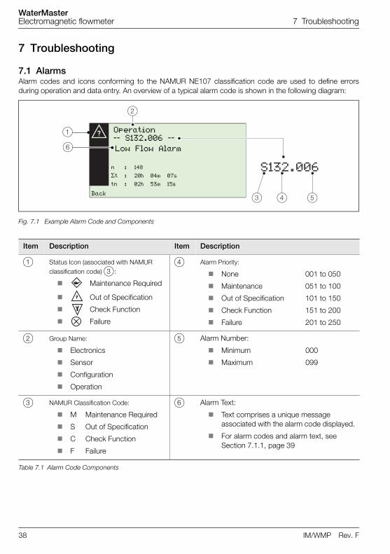
7.1 Alarms Alarm codes and icons conforming to the NAMUR NE107 classification code are used to define errorsduring operation and data entry. An overview of a typical alarm code is shown in the following diagram:
Fig. 7.1 Example Alarm Code and Components
Item Description Item Description
1 Status Icon (associated with NAMUR classification code) 3:
Maintenance Required
Out of Specification
Check Function
Failure
4 Alarm Priority:
None 001 to 050
Maintenance 051 to 100
Out of Specification 101 to 150
Check Function 151 to 200
Failure 201 to 250
2 Group Name:
Electronics
Sensor
Configuration
Operation
5 Alarm Number:
Minimum 000
Maximum 099
3 NAMUR Classification Code:
M Maintenance Required
S Out of Specification
C Check Function
F Failure
6 Alarm Text:
Text comprises a unique message associated with the alarm code displayed.
For alarm codes and alarm text, see Section 7.1.1, page 39
Table 7.1 Alarm Code Components
���'&&%
Operation –– S132.006 ––
Low Flow Alarm
Back
n : 148
t : 20h 04m 07s
tn : 02h 53m 15s
WaterMasterElectromagnetic flowmeter 7 Troubleshooting
IM/WMP Rev. F 39
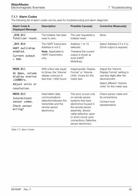
7.1.1 Alarm CodesThe following list of alarm codes can be used for troubleshooting and alarm diagnosis:
Alarm Code & Displayed Message
Description Possible Cause(s) Corrective Measure(s)
_030.012Totalizer reset.
The totalizer has been reset to zero.
The user requested a totalizer reset.
None
_044.014HART multidropenabled. Current output = 4mA.
The HART Instrument Address is not 0.
Note. Applicable to HART transmitters only.
Address 1 to 15 selected.
Therefore the current output is frozen at 4mA (HART Multidrop).
Select Address 0 if a 4 to 20mA output is required.
M080.011At Qmax, volume display overrun<1600hrs.Adjust units orresolution.
With a flow rate equal to Qmax, the 'Volume' display overruns in less than 1,600 hours.
Inappropriate 'Display Format' or 'Volume Units' choice for this meter size.
Adjust the 'Volume Display Format' setting to use less digits after the decimal point.
Select different 'Volume Units' for this meter size.
M090.013Intermittentsensor comms.Check sensorwiring?
Intermittent data communications detected between the transmitter and the remote sensor electronics.
This error occurs only on remote sensor systems that have electronics housed in the remote sensor assembly. Sensor cable defective; open or short-circuit; poor connections. Defective sensor electronics.
Check sensor cable and its connections.
Contact local representative.
Table 7.2 Alarm Codes
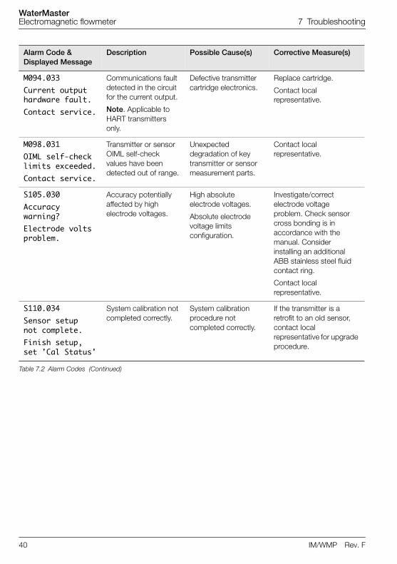
WaterMasterElectromagnetic flowmeter 7 Troubleshooting
40 IM/WMP Rev. F
M094.033Current outputhardware fault.Contact service.
Communications fault detected in the circuit for the current output.
Note. Applicable to HART transmitters only.
Defective transmitter cartridge electronics.
Replace cartridge.
Contact local representative.
M098.031OIML self-checklimits exceeded.Contact service.
Transmitter or sensor OIML self-check values have been detected out of range.
Unexpected degradation of key transmitter or sensor measurement parts.
Contact local representative.
S105.030Accuracywarning?Electrode voltsproblem.
Accuracy potentially affected by high electrode voltages.
High absolute electrode voltages.
Absolute electrode voltage limits configuration.
Investigate/correct electrode voltage problem. Check sensor cross bonding is in accordance with the manual. Consider installing an additional ABB stainless steel fluid contact ring.
Contact local representative.
S110.034Sensor setup not complete.Finish setup,set 'Cal Status'
System calibration not completed correctly.
System calibration procedure not completed correctly.
If the transmitter is a retrofit to an old sensor, contact local representative for upgrade procedure.
Alarm Code & Displayed Message
Description Possible Cause(s) Corrective Measure(s)
Table 7.2 Alarm Codes (Continued)
WaterMasterElectromagnetic flowmeter 7 Troubleshooting
IM/WMP Rev. F 41
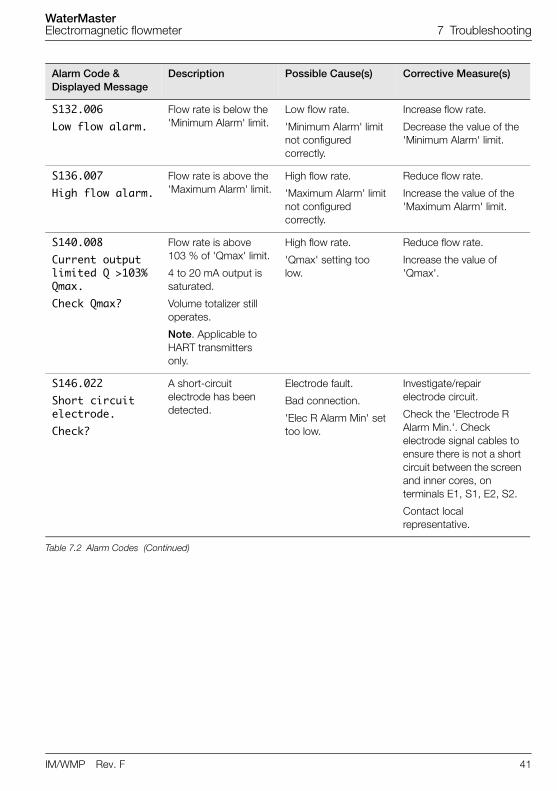
S132.006Low flow alarm.
Flow rate is below the 'Minimum Alarm' limit.
Low flow rate.
'Minimum Alarm' limit not configured correctly.
Increase flow rate.
Decrease the value of the 'Minimum Alarm' limit.
S136.007High flow alarm.
Flow rate is above the 'Maximum Alarm' limit.
High flow rate.
'Maximum Alarm' limit not configured correctly.
Reduce flow rate.
Increase the value of the 'Maximum Alarm' limit.
S140.008Current outputlimited Q >103% Qmax.Check Qmax?
Flow rate is above 103 % of 'Qmax' limit.
4 to 20 mA output is saturated.
Volume totalizer still operates.
Note. Applicable to HART transmitters only.
High flow rate.
'Qmax' setting too low.
Reduce flow rate.
Increase the value of 'Qmax'.
S146.022Short circuitelectrode. Check?
A short-circuit electrode has been detected.
Electrode fault.
Bad connection.
'Elec R Alarm Min' set too low.
Investigate/repair electrode circuit.
Check the 'Electrode R Alarm Min.'. Check electrode signal cables to ensure there is not a short circuit between the screen and inner cores, on terminals E1, S1, E2, S2.
Contact local representative.
Alarm Code & Displayed Message
Description Possible Cause(s) Corrective Measure(s)
Table 7.2 Alarm Codes (Continued)
WaterMasterElectromagnetic flowmeter 7 Troubleshooting
42 IM/WMP Rev. F
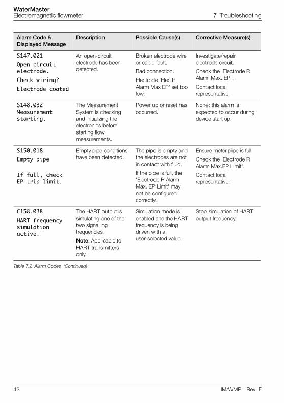
S147.021Open circuitelectrode. Check wiring?Electrode coated
An open-circuit electrode has been detected.
Broken electrode wire or cable fault.
Bad connection.
Electrode 'Elec R Alarm Max EP' set too low.
Investigate/repair electrode circuit.
Check the 'Electrode R Alarm Max. EP'.
Contact local representative.
S148.032Measurementstarting.
The Measurement System is checking and initializing the electronics before starting flow measurements.
Power up or reset has occurred.
None: this alarm is expected to occur during device start up.
S150.018Empty pipe
If full, checkEP trip limit.
Empty pipe conditions have been detected.
The pipe is empty and the electrodes are not in contact with fluid.
If the pipe is full, the 'Electrode R Alarm Max. EP Limit' may not be configured correctly.
Ensure meter pipe is full.
Check the 'Electrode R Alarm Max.EP Limit'.
Contact local representative.
C158.038HART frequencysimulationactive.
The HART output is simulating one of the two signalling frequencies.
Note. Applicable to HART transmitters only.
Simulation mode is enabled and the HART frequency is being driven with a user-selected value.
Stop simulation of HART output frequency.
Alarm Code & Displayed Message
Description Possible Cause(s) Corrective Measure(s)
Table 7.2 Alarm Codes (Continued)
WaterMasterElectromagnetic flowmeter 7 Troubleshooting
IM/WMP Rev. F 43
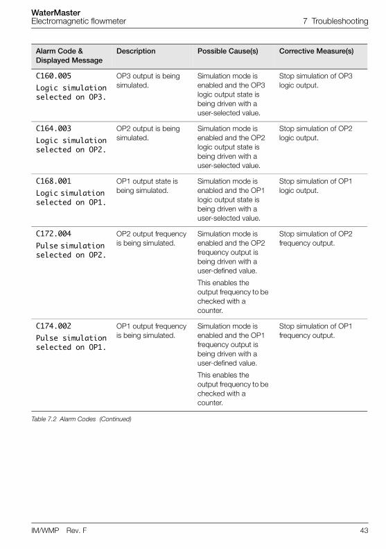
C160.005Logic simulationselected on OP3.
OP3 output is being simulated.
Simulation mode is enabled and the OP3 logic output state is being driven with a user-selected value.
Stop simulation of OP3 logic output.
C164.003Logic simulationselected on OP2.
OP2 output is being simulated.
Simulation mode is enabled and the OP2 logic output state is being driven with a user-selected value.
Stop simulation of OP2 logic output.
C168.001Logic simulation selected on OP1.
OP1 output state is being simulated.
Simulation mode is enabled and the OP1 logic output state is being driven with a user-selected value.
Stop simulation of OP1 logic output.
C172.004Pulse simulation selected on OP2.
OP2 output frequency is being simulated.
Simulation mode is enabled and the OP2 frequency output is being driven with a user-defined value.
This enables the output frequency to be checked with a counter.
Stop simulation of OP2 frequency output.
C174.002Pulse simulationselected on OP1.
OP1 output frequency is being simulated.
Simulation mode is enabled and the OP1 frequency output is being driven with a user-defined value.
This enables the output frequency to be checked with a counter.
Stop simulation of OP1 frequency output.
Alarm Code & Displayed Message
Description Possible Cause(s) Corrective Measure(s)
Table 7.2 Alarm Codes (Continued)
WaterMasterElectromagnetic flowmeter 7 Troubleshooting
44 IM/WMP Rev. F
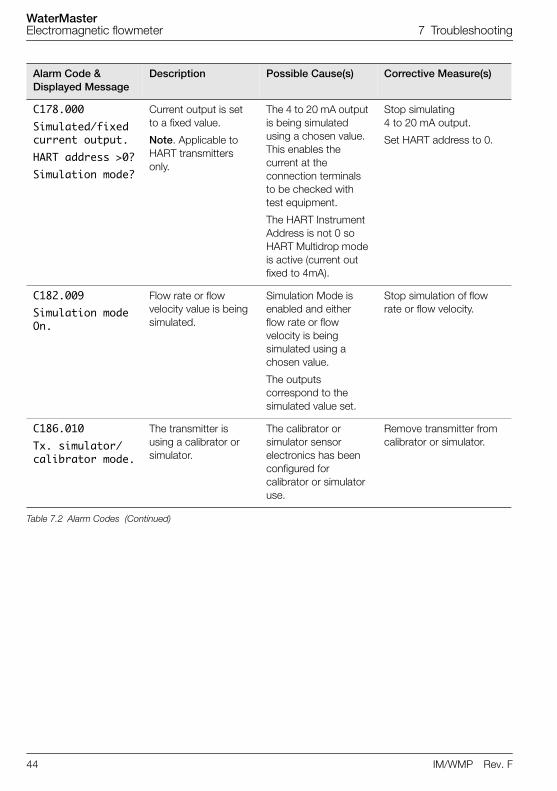
C178.000Simulated/fixedcurrent output.HART address >0?Simulation mode?
Current output is set to a fixed value.
Note. Applicable to HART transmitters only.
The 4 to 20 mA output is being simulated using a chosen value. This enables the current at the connection terminals to be checked with test equipment.
The HART Instrument Address is not 0 so HART Multidrop mode is active (current out fixed to 4mA).
Stop simulating 4 to 20 mA output.
Set HART address to 0.
C182.009Simulation modeOn.
Flow rate or flow velocity value is being simulated.
Simulation Mode is enabled and either flow rate or flow velocity is being simulated using a chosen value.
The outputs correspond to the simulated value set.
Stop simulation of flow rate or flow velocity.
C186.010Tx. simulator/calibrator mode.
The transmitter is using a calibrator or simulator.
The calibrator or simulator sensor electronics has been configured for calibrator or simulator use.
Remove transmitter from calibrator or simulator.
Alarm Code & Displayed Message
Description Possible Cause(s) Corrective Measure(s)
Table 7.2 Alarm Codes (Continued)
WaterMasterElectromagnetic flowmeter 7 Troubleshooting
IM/WMP Rev. F 45
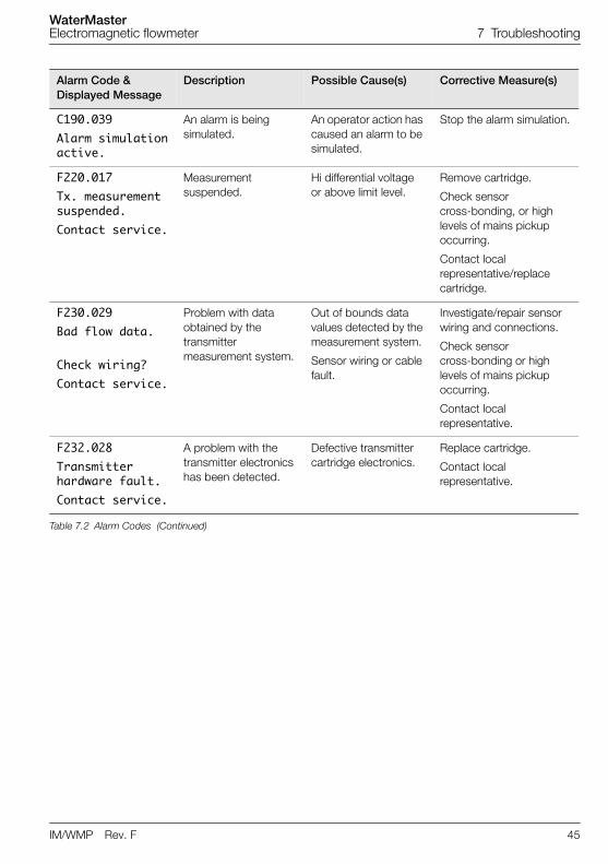
C190.039Alarm simulationactive.
An alarm is being simulated.
An operator action has caused an alarm to be simulated.
Stop the alarm simulation.
F220.017Tx. measurementsuspended.Contact service.
Measurement suspended.
Hi differential voltage or above limit level.
Remove cartridge.
Check sensor cross-bonding, or high levels of mains pickup occurring.
Contact local representative/replace cartridge.
F230.029Bad flow data.
Check wiring?Contact service.
Problem with data obtained by the transmitter measurement system.
Out of bounds data values detected by the measurement system.
Sensor wiring or cable fault.
Investigate/repair sensor wiring and connections.
Check sensor cross-bonding or high levels of mains pickup occurring.
Contact local representative.
F232.028Transmitterhardware fault.Contact service.
A problem with the transmitter electronics has been detected.
Defective transmitter cartridge electronics.
Replace cartridge.
Contact local representative.
Alarm Code & Displayed Message
Description Possible Cause(s) Corrective Measure(s)
Table 7.2 Alarm Codes (Continued)
WaterMasterElectromagnetic flowmeter 7 Troubleshooting
46 IM/WMP Rev. F
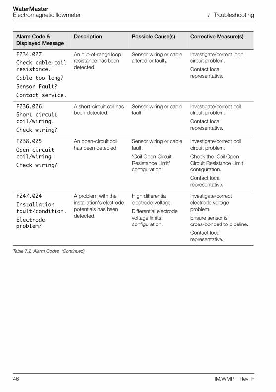
F234.027Check cable+coilresistance.Cable too long?Sensor Fault?Contact service.
An out-of-range loop resistance has been detected.
Sensor wiring or cable altered or faulty.
Investigate/correct loop circuit problem.
Contact local representative.
F236.026Short circuitcoil/wiring.Check wiring?
A short-circuit coil has been detected.
Sensor wiring or cable fault.
Investigate/correct coil circuit problem.
Contact local representative.
F238.025Open circuitcoil/wiring.Check wiring?
An open-circuit coil has been detected.
Sensor wiring or cable fault.
'Coil Open Circuit Resistance Limit' configuration.
Investigate/correct coil circuit problem.
Check the 'Coil Open Circuit Resistance Limit' configuration.
Contact local representative.
F247.024Installationfault/condition.Electrode problem?
A problem with the installation's electrode potentials has been detected.
High differential electrode voltage.
Differential electrode voltage limits configuration.
Investigate/correct electrode voltage problem.
Ensure sensor is cross-bonded to pipeline.
Contact local representative.
Alarm Code & Displayed Message
Description Possible Cause(s) Corrective Measure(s)
Table 7.2 Alarm Codes (Continued)
WaterMasterElectromagnetic flowmeter 7 Troubleshooting
IM/WMP Rev. F 47
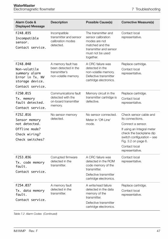
F248.035Incompatiblesensor.Contact service.
Incompatible transmitter and sensor calibration modes detected.
The transmitter and sensor calibration modes are not matched and the transmitter and sensor must not be used together.
Contact local representative.
F248.040Non-volatile summary alarmError in Tx. NVstorage device.Contact service.
A memory fault has been detected in the transmitter’s non-volatile memory.
A CRC failure was detected in the non-volatile memory. Defective transmitter cartridge electronics.
Replace cartridge.
Contact local representative.
F250.015Tx. memory fault detected.Contact service.
Communications fault detected with the on-board transmitter memory.
Memory circuit in the transmitter cartridge is defective.
Replace cartridge.
Contact local representative.
F252.016Sensor memorynot detected.Offline mode?Check wiring?Check switches?
No sensor memory detected.
No sensor connected.
Meter in 'Off-Line' mode.
Check sensor cable and its connections.
Connect a sensor.
If using an Integral meter check the backplane dip switch configuration – see Fig. 3.2 on page 6.
Contact local representative.
F253.036Tx. code memoryfault. Contact service.
Corrupted firmware detected in the transmitter.
A CRC failure was detected in the ROM code memory of the transmitter.
Defective transmitter cartridge electronics.
Contact local representative.
F254.037Tx. data memoryfault.Contact service.
A memory fault detected in the transmitter.
A write/read failure detected in the data memory of the transmitter.
Defective transmitter cartridge electronics.
Replace cartridge.
Contact local representative.
Alarm Code & Displayed Message
Description Possible Cause(s) Corrective Measure(s)
Table 7.2 Alarm Codes (Continued)
WaterMasterElectromagnetic flowmeter 8 Remote Computer Connection
48 IM/WMP Rev. F
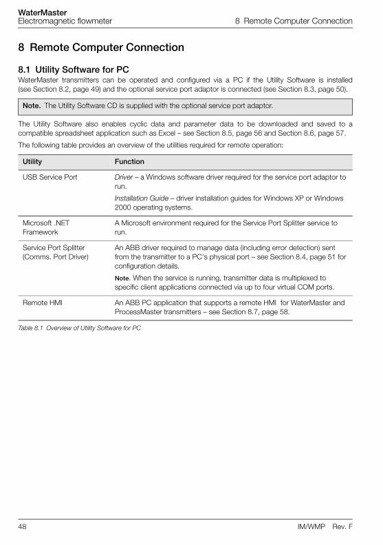
8 Remote Computer Connection
8.1 Utility Software for PCWaterMaster transmitters can be operated and configured via a PC if the Utility Software is installed(see Section 8.2, page 49) and the optional service port adaptor is connected (see Section 8.3, page 50).
The Utility Software also enables cyclic data and parameter data to be downloaded and saved to acompatible spreadsheet application such as Excel – see Section 8.5, page 56 and Section 8.6, page 57.
The following table provides an overview of the utilities required for remote operation:
Note. The Utility Software CD is supplied with the optional service port adaptor.
Utility Function
USB Service Port Driver – a Windows software driver required for the service port adaptor to run.
Installation Guide – driver installation guides for Windows XP or Windows 2000 operating systems.
Microsoft .NET Framework
A Microsoft environment required for the Service Port Splitter service to run.
Service Port Splitter (Comms. Port Driver)
An ABB driver required to manage data (including error detection) sent from the transmitter to a PC's physical port – see Section 8.4, page 51 for configuration details.
Note. When the service is running, transmitter data is multiplexed to specific client applications connected via up to four virtual COM ports.
Remote HMI An ABB PC application that supports a remote HMI for WaterMaster and ProcessMaster transmitters – see Section 8.7, page 58.
Table 8.1 Overview of Utility Software for PC
WaterMasterElectromagnetic flowmeter 8 Remote Computer Connection
IM/WMP Rev. F 49
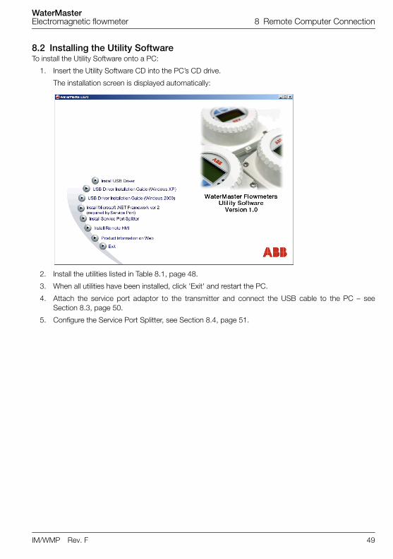
8.2 Installing the Utility SoftwareTo install the Utility Software onto a PC:
1. Insert the Utility Software CD into the PC’s CD drive.
The installation screen is displayed automatically:
2. Install the utilities listed in Table 8.1, page 48.
3. When all utilities have been installed, click 'Exit' and restart the PC.
4. Attach the service port adaptor to the transmitter and connect the USB cable to the PC – seeSection 8.3, page 50.
5. Configure the Service Port Splitter, see Section 8.4, page 51.
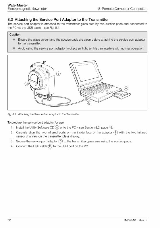
WaterMasterElectromagnetic flowmeter 8 Remote Computer Connection
50 IM/WMP Rev. F
8.3 Attaching the Service Port Adaptor to the TransmitterThe service port adaptor is attached to the transmitter glass area by two suction pads and connected tothe PC via the USB cable – see Fig. 8.1.
To prepare the service port adaptor for use:
1. Install the Utility Software CD A onto the PC – see Section 8.2, page 49.
2. Carefully align the two infrared ports on the inside face of the adaptor B with the two infraredsensor channels on the transmitter glass display.
3. Secure the service port adaptor C to the transmitter glass area using the suction pads.
4. Connect the USB cable D to the USB port on the PC.
Caution.
Ensure the glass screen and the suction pads are clean before attaching the service port adaptorto the transmitter.
Avoid using the service port adaptor in direct sunlight as this can interfere with normal operation.
Fig. 8.1 Attaching the Service Port Adaptor to the Transmitter
A
B
D
C

WaterMasterElectromagnetic flowmeter 8 Remote Computer Connection
IM/WMP Rev. F 51
8.4 Configuring the Service Port Splitter
8.4.1 Configuration OverviewThe Service Port Splitter can be configured to assign up to four virtual COM ports to individual clientapplications. Data can be transmitted to different virtual ports concurrently.
A typical virtual port configuration could contain the following settings:
Client 1 – assigned to the remote HMI application.
Client 2 – assigned a HART-compatible application.
Client 3 – assigned to output cyclic data (to an Excel worksheet).
Client 4 – assigned to output parameter data (to an Excel worksheet or a text file). The parameterdata includes configuration settings.
Fig. 8.2 is a representation of a typical virtual port configuration (COM numbers are selected duringconfiguration – see Section 8.4.2, page 52):
Fig. 8.2 Typical Service Port Splitter Configuration
Client 2
HART(Compatible Application)
Client 1
HMI
Client 4
Hyperterminal(Cyclic Data
Out)
Client 7
Hyperterminal(Parameter Dump
SP Client)
COM 6 COM 7 COM 8 COM 9
Service Port Splitter
COM 4
Service Port Adaptor
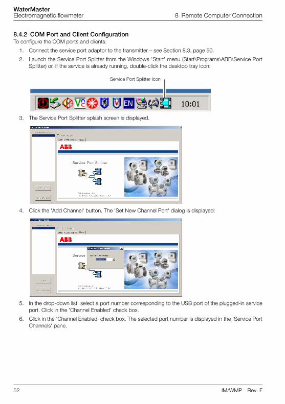
WaterMasterElectromagnetic flowmeter 8 Remote Computer Connection
52 IM/WMP Rev. F
8.4.2 COM Port and Client ConfigurationTo configure the COM ports and clients:
1. Connect the service port adaptor to the transmitter – see Section 8.3, page 50.
2. Launch the Service Port Splitter from the Windows 'Start' menu (Start\Programs\ABB\Service PortSplitter) or, if the service is already running, double-click the desktop tray icon:
3. The Service Port Splitter splash screen is displayed.
4. Click the 'Add Channel' button. The 'Set New Channel Port' dialog is displayed:
5. In the drop-down list, select a port number corresponding to the USB port of the plugged-in serviceport. Click in the 'Channel Enabled' check box.
6. Click in the 'Channel Enabled' check box. The selected port number is displayed in the 'Service PortChannels' pane.
Service Port Splitter Icon
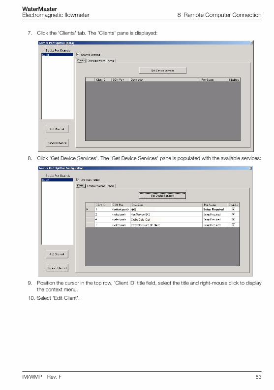
WaterMasterElectromagnetic flowmeter 8 Remote Computer Connection
IM/WMP Rev. F 53
7. Click the 'Clients' tab. The 'Clients' pane is displayed:
8. Click 'Get Device Services'. The 'Get Device Services' pane is populated with the available services:
9. Position the cursor in the top row, 'Client ID' title field, select the title and right-mouse click to displaythe context menu.
10. Select 'Edit Client'.
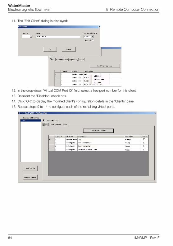
WaterMasterElectromagnetic flowmeter 8 Remote Computer Connection
54 IM/WMP Rev. F
11. The 'Edit Client' dialog is displayed:
12. In the drop-down 'Virtual COM Port ID' field, select a free port number for this client.
13. Deselect the 'Disabled' check box.
14. Click 'OK' to display the modified client’s configuration details in the 'Clients' pane.
15. Repeat steps 9 to 14 to configure each of the remaining virtual ports.
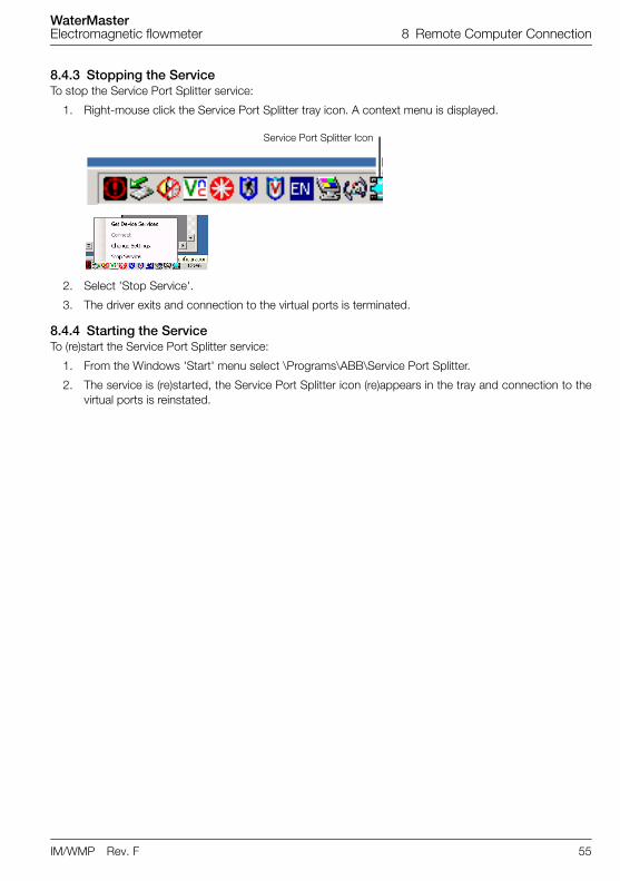
WaterMasterElectromagnetic flowmeter 8 Remote Computer Connection
IM/WMP Rev. F 55
8.4.3 Stopping the Service To stop the Service Port Splitter service:
1. Right-mouse click the Service Port Splitter tray icon. A context menu is displayed.
2. Select 'Stop Service'.
3. The driver exits and connection to the virtual ports is terminated.
8.4.4 Starting the Service To (re)start the Service Port Splitter service:
1. From the Windows 'Start' menu select \Programs\ABB\Service Port Splitter.
2. The service is (re)started, the Service Port Splitter icon (re)appears in the tray and connection to thevirtual ports is reinstated.
Service Port Splitter Icon
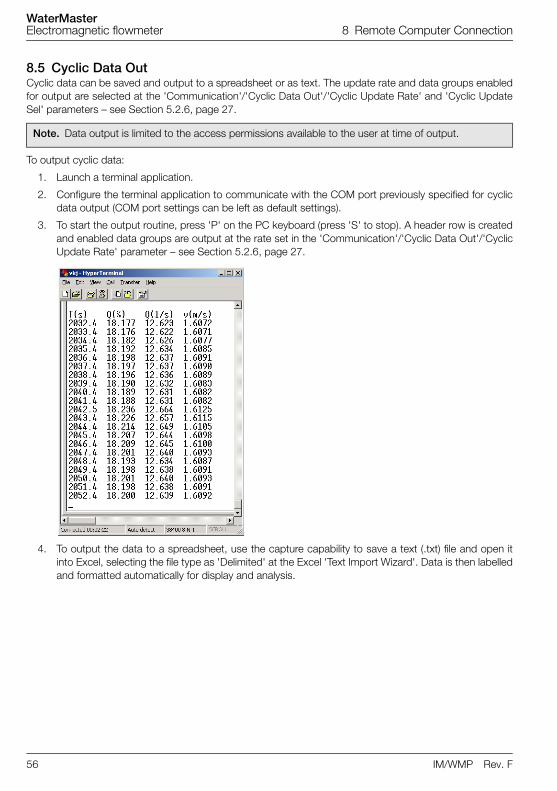
WaterMasterElectromagnetic flowmeter 8 Remote Computer Connection
56 IM/WMP Rev. F
8.5 Cyclic Data OutCyclic data can be saved and output to a spreadsheet or as text. The update rate and data groups enabledfor output are selected at the 'Communication'/'Cyclic Data Out'/'Cyclic Update Rate' and 'Cyclic UpdateSel' parameters – see Section 5.2.6, page 27.
To output cyclic data:
1. Launch a terminal application.
2. Configure the terminal application to communicate with the COM port previously specified for cyclicdata output (COM port settings can be left as default settings).
3. To start the output routine, press 'P' on the PC keyboard (press 'S' to stop). A header row is createdand enabled data groups are output at the rate set in the 'Communication'/'Cyclic Data Out'/'CyclicUpdate Rate' parameter – see Section 5.2.6, page 27.
4. To output the data to a spreadsheet, use the capture capability to save a text (.txt) file and open itinto Excel, selecting the file type as 'Delimited' at the Excel 'Text Import Wizard'. Data is then labelledand formatted automatically for display and analysis.
Note. Data output is limited to the access permissions available to the user at time of output.
WaterMasterElectromagnetic flowmeter 8 Remote Computer Connection
IM/WMP Rev. F 57
8.6 Parameter Dump
The parameter dump option enables two types of information to be gathered:
Configuration information
Signals and Alarm information
To run a Configuration parameter dump:
1. Launch a terminal application.
2. Configure the terminal application to communicate with the COM port specified for the 'ParameterDump SP Client'.
3. To start the output routine, press 'C' on the PC keyboard. Parameter data and configuration settingsare displayed by the terminal application.
4. To output the data to a spreadsheet, capture the data as a text (.txt) file, open it into Excel and selectthe file type as 'Delimited' using a ';' delimiter at the Excel 'Text Import Wizard'.
To run a Signals and Alarm parameter dump:
1. Launch a terminal application.
2. Configure the terminal application to communicate with the COM port specified for the 'ParameterDump SP Client'.
3. To start the output routine, press 'I' on the PC keyboard. A header row is created and parameterdata and configuration settings are imported into Hyperterminal.
4. To output the data to a spreadsheet, capture the data as a text (.txt) file, open it into Excel and selectthe file type as 'Delimited' using a ';' delimiter at the Excel 'Text Import Wizard'.
Note. Data output is limited to the access permissions available to the user at time of output.
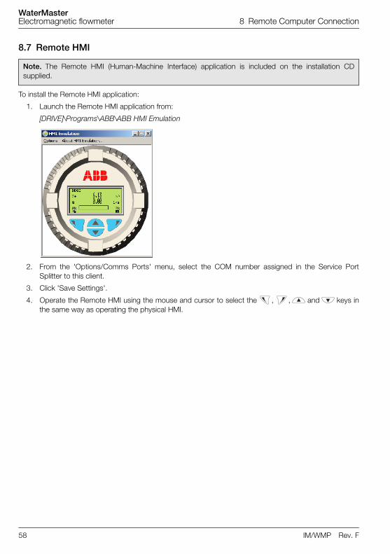
WaterMasterElectromagnetic flowmeter 8 Remote Computer Connection
58 IM/WMP Rev. F
8.7 Remote HMI
To install the Remote HMI application:
1. Launch the Remote HMI application from:
[DRIVE]\Programs\ABB\ABB HMI Emulation
2. From the 'Options/Comms Ports' menu, select the COM number assigned in the Service PortSplitter to this client.
3. Click 'Save Settings'.
4. Operate the Remote HMI using the mouse and cursor to select the , , and keys inthe same way as operating the physical HMI.
Note. The Remote HMI (Human-Machine Interface) application is included on the installation CDsupplied.
WaterMasterElectromagnetic flowmeter 8 Remote Computer Connection
IM/WMP Rev. F 59
8.8 HART Client
To run the HART client:
1. Ensure the ABB Service Port Splitter is installed and running.
2. Ensure a COM port is assigned to the HART Application as detailed in Section 8.4.2, page 52.
3. Launch any preferred PC HART application, such as SMARTVision or similar.
4. Configure the COM port on the running HART application to be the COM port assigned in step 1above.
The HART application operates as normal allowing any HART command to be read or written.
Note. Any standard HART application can be used via the infrared service port and ABB Service PortSplitter utility. All communications are handled automatically with no need for a HART modem. (HARTclient for WaterMaster's Service Port is available in all WaterMaster variants.)
Note. An increase in operating speed may be noticed because HART communication transmits fasterthrough the service port than through a normal HART modem.

WaterMasterElectromagnetic flowmeter Notes
60 IM/WMP Rev. F
Notes
���������
�� ��� �� �
�������������� ��������������������������������� ������������������ ����������� ��
�
������
�������
����
������������ ��������� ���������� ��������� ����!���� ��������
!���� �"�#�������$ ����%"�&�������$ ����%"�'� ��������
����
����
������
������
"�#�"�&��� ����
���� ������
������
(��������)�*����(��������*������+�*����������,����*������������������ ������
���������
����������������������
����������
��� �� � ������������� ���� �!���-�����.� ����.������
"��� ������,������!�����*�����,������/��������-� �( ��0���������-� ����+�����������*����� ��������
�� �*������1�*�����0���� ���#2'3
����
����
������
����� ������
����
,*�4!������"���������� ��0�������
"�0����*������,*�4�4��,*�4�"����������� �.��������("�����,*�4�!���� �!���� ���������,*�4"�0�����������
���� ������
!�����������������!������������� ��5
���� ������
��������������
������
������
����� ����
�� 5�*������15�*����
���� ������
������������ ��
������� ����
"�#������"�#�!� .��"�#�*���� "�&������"�&�!� .��"�&�*���� "�'������"�'�!� .��"�'�*����
������ ����
����� ����
!���� ��������66
/��������-� �
( ��0���������-� �
���+�����������
,*�4666
!������"�������
��1�7������������ ������
��0�������
���������
����!��"
������
� ����!��
����
������4�����8��
���������"��������)��������9)4*���������
���� ������
����
������4�����8��
���������
��#������
������
���#������
����
�������� ��������� ������������������9��*�*77�"��� ������
�������� �����
)���5���*�������1�))���5���*������� )���5��:������)���5��;������)���5���"�..������!����(�*�����7� �!������!��������!���� �!��������
����
���� �$
)���5���)#)���5���)&"!�7��-��..��!�����!�<����!����� � ������ ��.�415�*05�/�� � ��.�����
%
�$
�$
�� ����=���*41�!��>���������� ���!��>���������� �������������������� ������
������)����������)���������.��)�����4�� ���������������� � �������������� ������������� � ������������ �������*�������� ������
����
��������
��������� ��
������
����������
9��*�
�
���������
�����&��
����������
4�� ������������"�.�����
4?� �� 4?�@�������
'(����
4�� �������
���&��
������
�������
����
�����"�.�����
������
�
�
9� �
��(���� �����������������#� ����������������#� �����������������&� ����������������&� �����������������'� ������������ ����+����������1����+��������#2'3���������� ������������+��!���<�������"��������0���� ��
*����� ��������
���� �)�
���
*���� ������
����
���������
Key: Advanced AccessStandard Access
Refer to: Section 5.2.4, page 22 Refer to: Section 5.2.6, page 27 Refer to: Section 5.2.8, page 30Refer to: Section 5.2.7, page 29Refer to: Section 5.2.5, page 25
Note. If 'Pulse Mode' isset to 'Fullscale Frequency'
the ‘Fullscale Frequency’menu is displayed. If 'Pulse
Mode' is set to 'Pulse /Unit', the 'Pulses / Unit'
menu is displayed.
Note. Refer to Section5.2.4, page 22 for 'Pulse/State' display conditions.
Display (4)(Inside front cover)
* These screens are not displayed at 'Read Only' level.** The 'Current Output' menu is displayed on HART WaterMaster variants only.*** The HART menu is displayed on all WaterMaster variants, but only affects HART via the Service Port if the WaterMaster does not have a HART transmitter.
Other comms options (for example PROFIBUS) appear after the Service Port menu depending on the transmitter variant.
Contact us
IM/W
MP
Rev
. F05
.201
4
Products and customer support
Automation SystemsFor the following industries:— Chemical & Pharmaceutical— Food & Beverage— Manufacturing— Metals and Minerals— Oil, Gas & Petrochemical— Pulp and Paper
Drives and Motors— AC and 6 Drives, AC and DC Machines, AC Motors
to 1kV— Drive Systems— Force Measurement— Servo Drives
Controllers & Recorders— Single and Multi-loop Controllers— Circular Chart and Strip Chart Recorders— Paperless Recorders— Process Indicators
Flexible Automation— Industrial Robots and Robot Systems
Flow Measurement— Electromagnetic Flowmeters— Mass Flowmeters— Turbine Flowmeters— Wedge Flow Elements
Marine Systems & Turbochargers— Electrical Systems— Marine Equipment— Offshore Retrofit and Refurbishment
Process Analytics— Process Gas Analysis— Systems Integration
Transmitters— Pressure— Temperature— Level— Interface Modules
Valves, Actuators and Positioners— Control Valves— Actuators— Positioners
Water, Gas & Industrial Analytics Instrumentation— pH, Conductivity and Dissolved Oxygen
Transmitters and Sensors— Ammonia, Nitrate, Phosphate, Silica, Sodium,
Chloride, Fluoride, Dissolved Oxygen and Hydrazine Analyzers
— Zirconia Oxygen Analyzers, Katharometers, Hydrogen Purity and Purge-gas Monitors, Thermal Conductivity
Customer supportWe provide a comprehensive after sales service via a Worldwide Service Organization. Contact one of the following offices for details on your nearest Service and Repair Centre.
UKABB LimitedTel: +44 (0)1453 826661Fax: +44 (0)1453 829671
USAABB Inc.Tel: +1 215 674 6000Fax: +1 215 674 7183
Client WarrantyPrior to installation, the equipment referred to in this manual must be stored in a clean, dry environment, in accordance with the Company's published specification.Periodic checks must be made on the equipment's condition. In the event of a failure under warranty, the following documentation must be provided as substantiation:— A listing evidencing process operation and
alarm logs at time of failure.— Copies of all storage, installation, operating and
maintenance records relating to the alleged faulty unit.
ABB LimitedProcess AutomationOldends LaneStonehouseGloucestershire GL10 3TAUKTel:+44 1453 826 661Fax:+44 1453 829 671
ABB Inc.Process Automation125 E. County Line RoadWarminsterPA 18974USATel:+1 215 674 6000Fax:+1 215 674 7183
www.abb.com
NoteWe reserve the right to make technical changes or modify the contents of this document without prior notice. With regard to purchase orders, the agreed particulars shall prevail. ABB does not accept any responsibility whatsoever for potential errors or possible lack of information in this document.
We reserve all rights in this document and in the subject matter and illustrations contained therein. Any reproduction, disclosure to third parties or utilization of its contents – in whole or in parts – is forbidden without prior written consent of ABB.
Copyright© 2014 ABBAll rights reserved