Embed Size (px)
Citation preview

BMS Water/Methanol/Alcohol WMI Kit Install Guide
Last updated 3/13/2017
Use subject to terms and conditions posted at
http://www.burgertuning.com/terms.html
THIS PART IS LEGAL FOR USE ONLY IN COMPETITION RACING VEHICLES
AS DEFINED UNDER CALIFORNIA LAW, AND IS NOT LEGAL FOR USE IN
ANY OTHER MOTOR VEHICLE. California law defines a "racing vehicle" as "a
competition vehicle not used on public highways." (Calif. Health & Safety Code 39048)
This part may only be used on competition racing vehicles operated exclusively on a
closed course in conjunction with a sanctioned racing event. Competition-only motor
vehicles may not be driven to a racing event on a public highway and must be transported
on a trailer or other carrier. USE OF THIS PART IN ANY OTHER VEHICLE MAY
SUBJECT YOU TO FINES AND PENALTIES FOR VIOLATION OF FEDERAL
AND/OR STATE LAW, WILL VOID YOUR WARRANTY FROM BURGER
MOTORSPORTS, INC, AND CAN VOID YOUR VEHICLE'S WARRANTY. It is your
responsibility to comply with all applicable federal and state laws relating to use of this
part, and Burger Motorsports, Inc hereby disclaims any liability resulting from the failure
to use this part in compliance with all
applicable federal and state laws.
Always be aware that using water/methanol/alcohol injection involves risk of fire and
engine damage and care should be taken to reduce these risks.
Remove the cowl covers for the model to expose the JB4 control box, and remove the
negative battery terminal.
The FSB serves as both the pump controller and the flow sensor. It comes with plug and
play connectors ready to install in the JB4 large 25pin connector. Note there are two
version FSB systems. The original version has one side of the box open so you can see
the circuit board while version 2 sits completely inside a closed enclosure. The original
version has a red wire for the pump power while version 2 has a yellow wire for pump
power. Note reference photos below. The main difference in installation between the two
will be whether the 2nd
solenoid wire is connected to the pump red (original) or ground
(version 2).

FSB Wiring:
1) Orange/Blue wires. Same for original and rev2:
N54:
Remove the JB4 control box from the AMP connector and remove the two screws
holding the AMP connector together. Upon removing the case you'll insert the FSB
orange wire in to position #2 and the blue wire in to position #15. These will be the only
open slots in the connector. They are numbered on both the front and back so check
before pushing the pin in.
If you lock the pin in the wrong spot by mistake you will need to go to Radio Shack or an
electronics store to get an inexpensive tool called a "DSUB pin removal tool" to extract
the pin and place it in the right slot. If you manage to damage a pin you can replace it
with any male DSUB pin.
All other engines:
All N20, N55, N63, S55, S63, B48, B58, VW, etc, applications use spot #3 for the orange
wire.
Blue Wire:
#16: pneumatic wastegate board vehicles (E series N55 and 2013 F series N20/N55)
#16: VW, N63, S55, S63TU
#14: 2014+ F series N20/N55/B48/B58
If the blue wire is placed in the wrong spot the pump will still turn on but the JB4 will not
properly read flow data.
2) Ground: Route the black ground out of the DME box to a chassis ground. A bad
ground can damage the FSB resulting in WMI getting stuck on while ignition is on so
find a ground that has OEM ground wires (normally brown) going to it. The F series
shock tower or random chassis bolts are generally not suitable ground points.
Suitable ground point with factory wires attached to it:
3) FSB Red Wire +12v. Same for original and rev2:
N54:
For N54 installs the FSB power wire with the connector attached to it (the one on the
same side as the black ground wire) piggybacks with the JB4 red power wire. The one
that is attached to the green connector in the DME box. Unplug the OEM orange wire
from the JB4 power wire, connect the FSB female pin to it, and connect the FSB male pin
to the JB4 power wire completing the loop. Now, both the JB4 and the FSB control box
will have switched 12v power. For the N54 the fuse will go between the FSB red wire to
the pump and the pump.
N55 E Series:
Cut off the FSB power connector, attach the FSB red wire to the included inline fuse with
a wire nut, strip back the insulation round 1”on the other side of the inline fuse holder,
and attach the wire to the large 50amp fuse location that the JB4 takes its power from by
removing the 50amp fuse, putting the wire in the 50amp fuse holder, and pushing the
50amp fuse back down securing it in place.
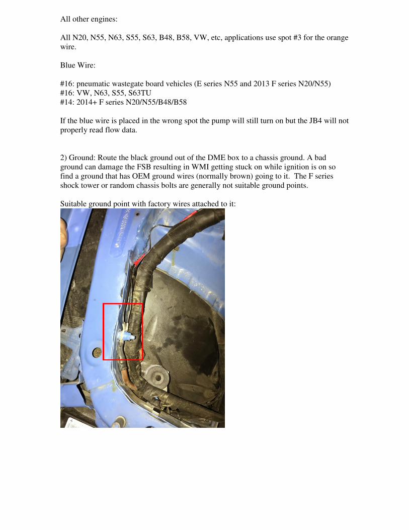
All F Series:
Cut off the 12v pnp connector from the FSB red wire and attach it to one side of the
inline fuse holder. Crimp a fork on the other side of the inline fuse holder and plug that in
to an unused fused location in the primary fuse box shown below. Note many unused
spots DO NOT have a fuse receptacle and won’t work so be sure to locate one that has an
actual power feed below it.
4) PUMP POWER
Original FSB:
Extend the red wire to the WMI pump located in the trunk and attach with a wirenut.
V2 FSB:
Extend the yellow wire to the WMI pump located in the trunk and attach with a wirenut.
5) SOLENOID WIRING.
Original FSB: Both solenoid wires are interchangeable. Attach one to the FSB green
connection using spare wire as needed to extend it. Attach the other solenoid wire to the
RED wire going to the WMI pump from step4.
V2 FSB: Both solenoid wires are interchangeable. Attach one to the FSB green
connection using spare wire as needed to extend it. Attach the other solenoid wire to a
suitable ground location by the solenoid.
6) Pump ground: The pump black wire will be connected to a chassis ground in the trunk.
You can use the battery directly or one of the many exposed grounds under the trunk
liner.
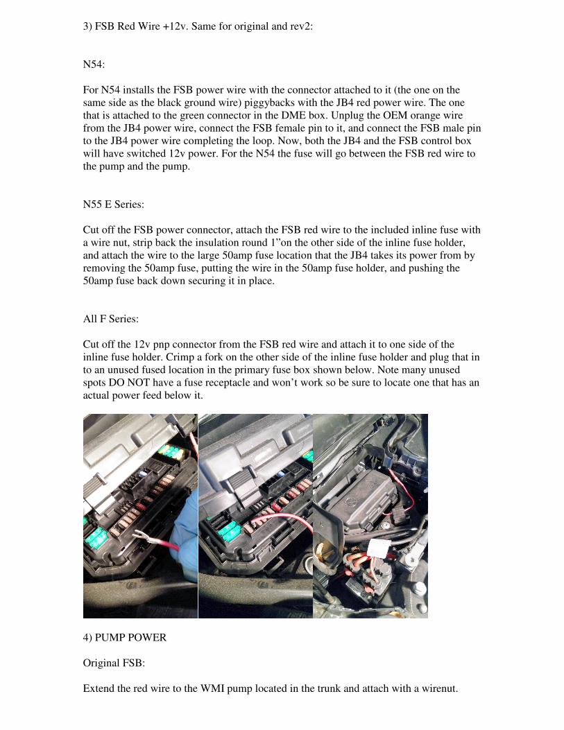
Fittings:
We've updated the BMS WMI kits with new compression style fittings. The solenoid will
go together as shown below. Note the direction of flow on the solenoid and filter fitting
during assembly. Line will run from the PUMP, to the filter, to the solenoid, and finally
out the solenoid to the nozzles (or nozzle tee if a twin nozzle kit).
To install these fittings apply a small amount of Teflon paste to the threads and tighten
them. Then insert the nylon line in to the fitting and turn the compression nut with a
wrench until snug.
Tank Assembly:
Coolingmist 2.3g tank:
1) Separate the tank from the mount by removing the two long screws.
2) Apply a small amount of thread sealant on the 1/4" NPT brass compression fitting and
screw it snugly in to the tank base.
3) Attach a one foot piece of line to the compression fitting and extend that line through
the tank base opening while sliding the tank back on the base.
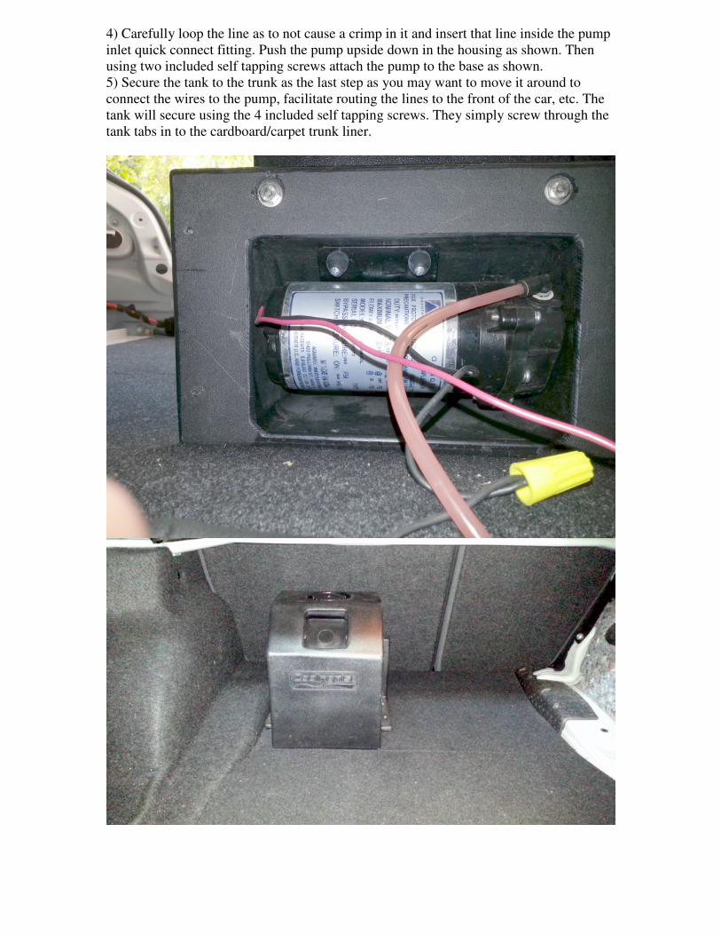
4) Carefully loop the line as to not cause a crimp in it and insert that line inside the pump
inlet quick connect fitting. Push the pump upside down in the housing as shown. Then
using two included self tapping screws attach the pump to the base as shown.
5) Secure the tank to the trunk as the last step as you may want to move it around to
connect the wires to the pump, facilitate routing the lines to the front of the car, etc. The
tank will secure using the 4 included self tapping screws. They simply screw through the
tank tabs in to the cardboard/carpet trunk liner.
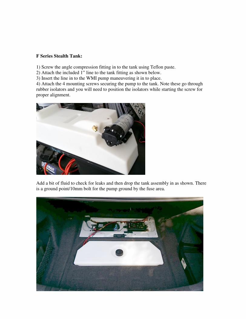
F Series Stealth Tank:
1) Screw the angle compression fitting in to the tank using Teflon paste.
2) Attach the included 1” line to the tank fitting as shown below.
3) Insert the line in to the WMI pump maneuvering it in to place.
4) Attach the 4 mounting screws securing the pump to the tank. Note these go through
rubber isolators and you will need to position the isolators while starting the screw for
proper alignment.
Add a bit of fluid to check for leaks and then drop the tank assembly in as shown. There
is a ground point/10mm bolt for the pump ground by the fuse area.
Routing lines:
We suggest running the lines and wires through the interior as we've found this the most
convenient method of install. But you also have the option to route the lines/wires under
the car, or any way you'd like, so rely on your own judgement here. Included are some
photos demonstrating how you may choose to route the lines:
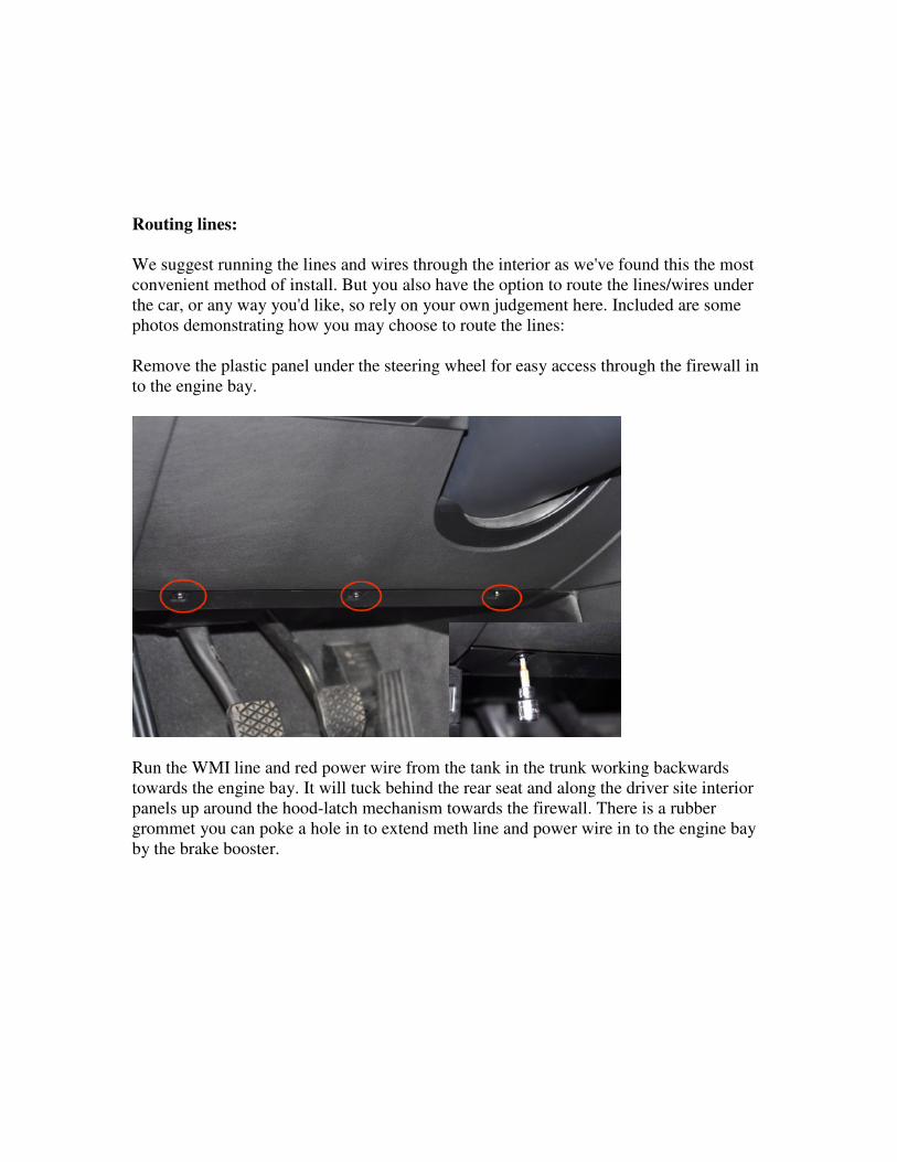
Remove the plastic panel under the steering wheel for easy access through the firewall in
to the engine bay.
Run the WMI line and red power wire from the tank in the trunk working backwards
towards the engine bay. It will tuck behind the rear seat and along the driver site interior
panels up around the hood-latch mechanism towards the firewall. There is a rubber
grommet you can poke a hole in to extend meth line and power wire in to the engine bay
by the brake booster.
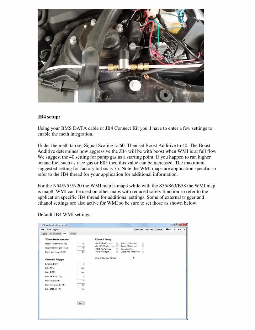
JB4 setup:
Using your BMS DATA cable or JB4 Connect Kit you'll have to enter a few settings to
enable the meth integration.
Under the meth tab set Signal Scaling to 60. Then set Boost Additive to 40. The Boost
Additive determines how aggressive the JB4 will be with boost when WMI is at full flow.
We suggest the 40 setting for pump gas as a starting point. If you happen to run higher
octane fuel such as race gas or E85 then this value can be increased. The maximum
suggested setting for factory turbos is 75. Note the WMI maps are application specific so
refer to the JB4 thread for your application for additional information.
For the N54/N55/N20 the WMI map is map3 while with the S55/S63/B58 the WMI map
is map8. WMI can be used on other maps with reduced safety function so refer to the
application specific JB4 thread for additional settings. Some of external trigger and
ethanol settings are also active for WMI so be sure to set those as shown below.
Default JB4 WMI settings:
WMI flow:
Note when the system is operating normally you will see a WMI flow reading of 60% to
100%. It's normal for the flow reading to vary between 60-100% based on weather, fluid
injected, nozzle size, etc. Readings below 60% indicate a flow issue. If you run out of
meth the reading will drop to 10% or less. If you have a wiring or electrical issue the
reading will drop to 0%.
Priming system:
The first time you install and any time you run the system dry you will need to prime the
pump to get all of the air out of the pump and lines. If you see air bubbles in the line
feeding the pump you will need to resolve that issue first and then prime to remove air
from the pump after. Any time air is detected in the pump or lines leading in to the pump
the JB4 will give a lower meth reading. Note it is normal to see air pockets in the short
line between the solenoid and the nozzle when the system is off. It is also normal to see
an occasional air bubble in the line feeding the pump. But many bubbles combined with a
consistent low flow reading indicate air is leaking in to the system.
N54 Purge Directions:
Disconnect the line from the nozzle and place it in a water bottle or bucket to catch the
fluid. Turn the ignition on and enter JB4 command mode. Go to option 7/5 (meth on oil
temp) and while in command mode press the gas pedal to the floor to activate the pump
and push the air out of the system. This generally takes 5-10 seconds and you can
visually confirm the inlet and outlet lines are free of air bubbles. If you see air bubbles
appearing in the line going towards the pump double check all fittings and lines to ensure
they are tight.
All others:
Select the JB4 WMI map. With ignition on and JB4 software connected press the small
“purge” button in the upper right hand corner repeatedly to activate/test the pump. Each
press will activate the pump for around a second and it should take 6-8 seconds to push
all the air from the pump and get it properly primed.
If you are unable to get fluid to come out using the methods above you have a wiring or
installation issue and will need to further troubleshoot. Assuming fluid comes out
everything should be working properly.
Troubleshooting:
Pump isn't turning on using 7/5 option + gas pedal push in dash:
1) Above technique works for N54 only
2) Orange and blue wires in JB4 might be crossed
3) Inline fuse installed may be missing or blown
FSB Mounting in F Series:
Although the FSB will be placed under a plastic engine cover it is still susceptible to
water damage if left floating. We suggest either mounting the FSB face down against the
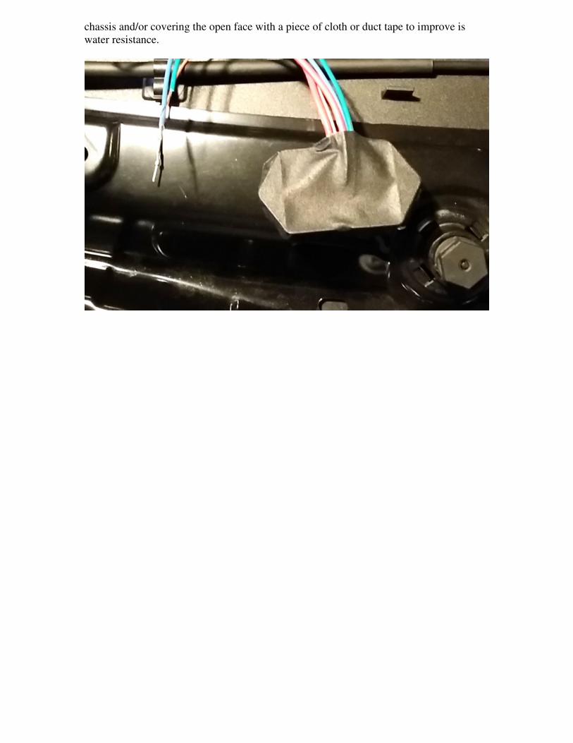
chassis and/or covering the open face with a piece of cloth or duct tape to improve is
water resistance.