Embed Size (px)
Citation preview

Use of Underwater Dry Welding for In‐Situ Repair to Offshore Structures
Sabine [email protected]
02/12/2016

In‐Situ Welding
Steel Structures
Suitability of Repair Methods
Mobile Offshore Units– Dry Docking Schedule (Inspection and Repair)
– Underwater Inspection In‐Lieu of Dry Dock (UWILD)
Fixed Offshore Units
2

Difficulties in Welding
Welding Challenges
Diver and Operational Challenges
3

Welding Challenges
Water– Rapid Cooling Rates– Hydrogen– Cracking
Ambient Pressure – Porosity
Material– Higher carbon content (Older)– Alloyed Steels
4
No Shielding Gas on Steel. [Online]. [Accessed 23 February 2015]. Available from: http://www.millerwelds.com

Operational Challenges
Welder Challenges– Environment
• Sea state and current• Visibility
– Weld Location• Access to Weld Area• Fatigue
– Technique
Repair Time Challenges– Diving weather window– Depth limited dive time
5
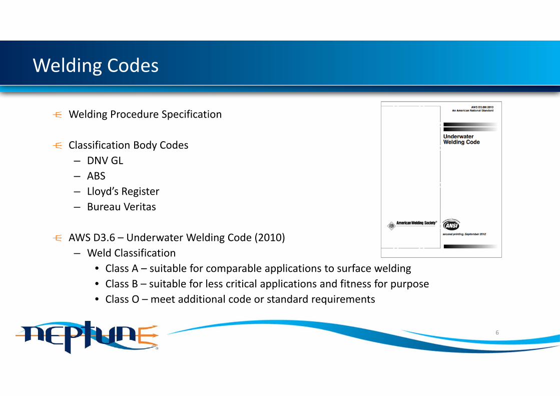
Welding Codes
Welding Procedure Specification
Classification Body Codes– DNV GL – ABS– Lloyd’s Register– Bureau Veritas
AWS D3.6 – Underwater Welding Code (2010)– Weld Classification
• Class A – suitable for comparable applications to surface welding• Class B – suitable for less critical applications and fitness for purpose• Class O – meet additional code or standard requirements
6

Welding Procedure Specification
A document which outlines the steps to be followed to produce a weld with the required properties.
Some Essential Variables:Depth– Ambient PressureSteel chemical composition (Carbon and Carbon Equivalent)– Hardenability (350HV10)Welding consumablesPre‐ and Post‐ Heating
7

Welding Procedure Specification and Test Macro
8
Macro 38mm ABS EH 36 Plate Butt weldMacro 38mm ABS EH 36 Plate Butt weld
Macro 20mm ABS EH 36 Plate Butt weld Macro 20mm ABS EH 36 Plate Butt weld

Weld Classes
Class A Class BVisual Inspection / Surface Inspection
No visible cracks, porosity, or inclusions
No visible cracks
Maximum undercut 1.5mm Maximum undercut 3mm
Material Properties Weld metal yield and tensile strength to meet or exceed base material specification
Weld metal tensile strength to meet or exceed base material specification
Hardness below 325HV10 Hardness below 375HV10For specified tensile strength below 485MPa, average impact of 27J (minimum 14J)
For specified tensile strength below 485MPa, average impact of 20J (minimum 14J)
Non‐Destructive Testing
Radiographic Testing Radiographic TestingUltrasonic Testing
9

Methods of Underwater Welding
Wet WeldingWelding arc and weld is not separated from the water
10
Dry Spot Welding –NEPSYS
Weld is separated from the waterDiver is separated from the weld
Hyperbaric WeldingWeld is separated from the waterDiver is not separated from the weld

Welding Method Comparison
Wet Dry Spot (NEPSYS) HyperbaricTypical Quality Class B Class A Class ARepair Depth Achieved up to 100m Achieved up to 60m Achieved up to 400m
Repair Materials
Carbon Content <0.1%, and Carbon Equivalent <0.37%
Restrictions comparable to surface welding
Restrictions comparable to surface welding
Limited wet welding specific electrodes
Variety of electrodes may be used
Variety of electrodes may be used
ApplicationAlmost nil restrictions to weld area geometry
Some restrictions due to habitat size and weld area geometry
Restrictions due to chamber size and weld area geometry
SafetyWelder mobility Welder mobility Separation of Welder
and waterSeparation of Welder and weld
11

Typical Commercial Comparison
Wet Dry Spot (NEPSYS) Hyperbaric
Qualification and Set Up
Weld and Welder qualificationSmall habitat design / fabrication
Large chamber design / fabrication
ProjectMobilisation
PersonnelDiving spread
Welding equipment and consumables
Welding / habitat equipment and consumables
Welding / chamber equipment and consumables
Operations
Vessel / personnelWelding speed comparable tosurface welding
Habitat set up / removal by divers
Chamber set up / removal by vessel crane
Reduced Welding Speed Welding speed comparable to surface welding
12

Typical Commercial Comparison
Wet Dry Spot (NEPSYS) HyperbaricQualification and Set Up
Days to Weeks Weeks to Months MonthsLow Cost Medium Cost High Cost
Project Mobilisation
Days to Weeks Days to Weeks WeeksLow Cost Low to Medium Cost High Cost
Operations Small Vessel Small Vessel Larger Vessel including crane
Low number of dives Medium number of dives Low number of dives
13

Case Study ‐ NEPSYS System
Habitat which isolates the weld area is designed.– Accommodates the geometry of the area surrounding the weld
– Incorporates windows for visibility and access to the weld
Heated gas displaces the water, creating a dry, protected environment for weldingWelding Rods are coated and hermetically sealed to protect from the environment before being used in welding
14
Case Study ‐ NEPSYS System
15
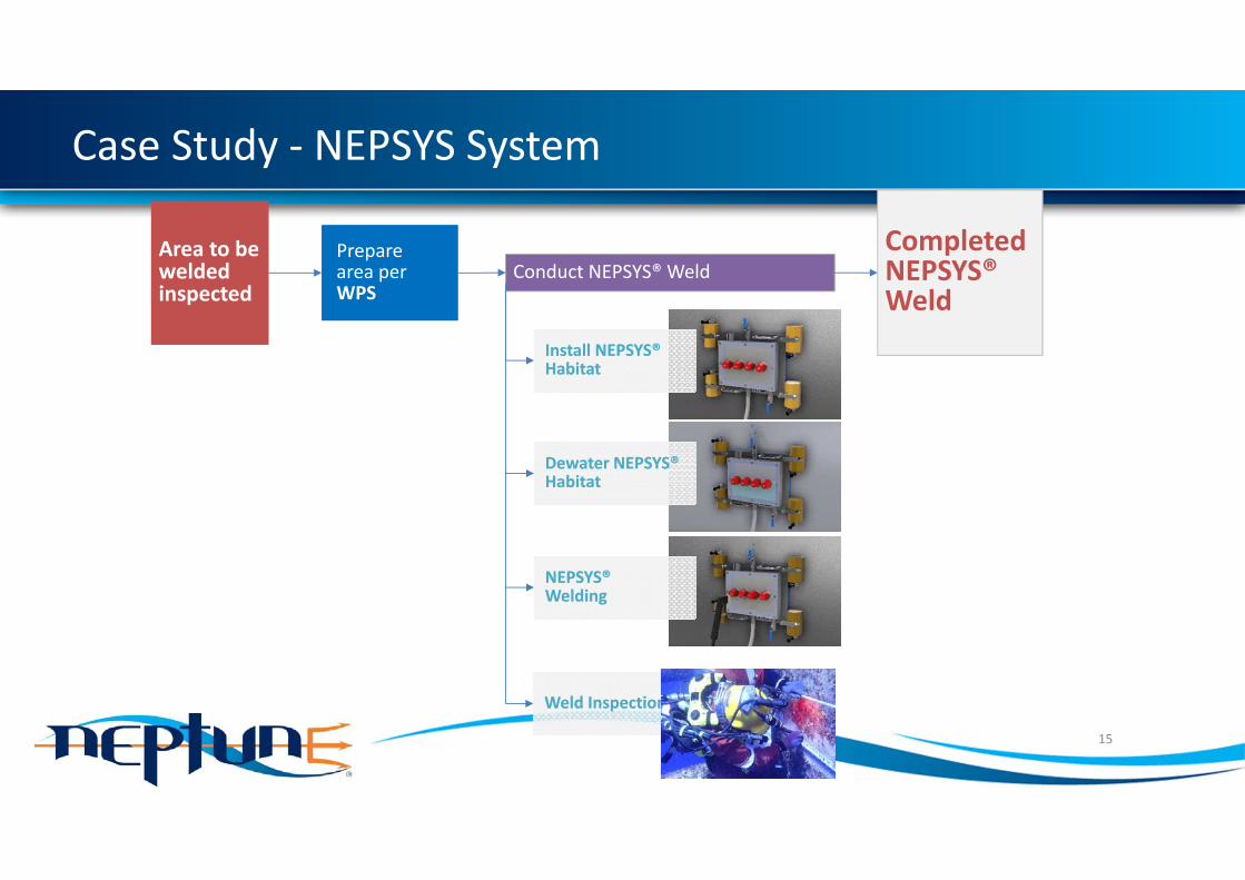
Area to be welded inspected
Area to be welded inspected
Completed NEPSYS® Weld
Conduct NEPSYS® Weld
Install NEPSYS® HabitatInstall NEPSYS® Habitat
Prepare area per WPS
Prepare area per WPS
Dewater NEPSYS® HabitatDewater NEPSYS® Habitat
NEPSYS® WeldingNEPSYS® Welding
Weld InspectionWeld Inspection

Case Study
1.5m diameter raked pileApproximately 25% of the circumference was damaged at ‐17m LAT Damage to the underside of the pileContacted by client in AugustGrouting of piles in October
Options for repair:– Removal and Re‐piling – Clamp– Repair Patch via wet weld– Reinstatement of Material via dry welding
16
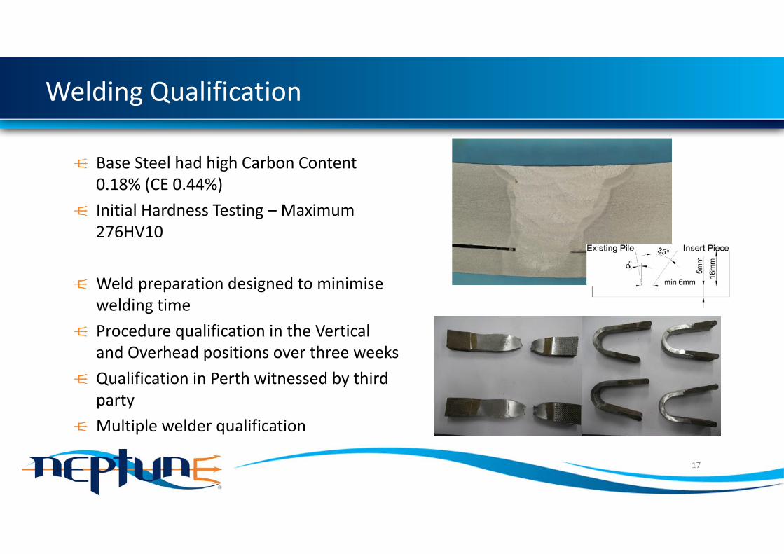
Welding Qualification
Base Steel had high Carbon Content 0.18% (CE 0.44%)Initial Hardness Testing – Maximum 276HV10
Weld preparation designed to minimise welding timeProcedure qualification in the Vertical and Overhead positions over three weeksQualification in Perth witnessed by third partyMultiple welder qualification
17

Insert Plate and Habitat Design
Insert plate design adapted for damage profile, welding procedure Habitat design adapted for insert plate profileHabitat fabrication (one week)
Removal of damaged area via water jetting which left edges suitable for weldingInsert plate installation allowed progression of grouting works
18

Operations
Mobilisation from Perth to Queensland of NEPSYS equipment and personnelOperations conducted with local dive spreadDiving from the back of a 15m work boatNitrox mixture used to ensure longer dive times at the repair depthFour qualified weldersApproximately 45 hours of welding2800mm of weld in 16mm plate
19

Results
Weld ground flush to the pileNo surface defects found via Magnetic Particle Inspection or Creep Wave Ultrasonic TestingNo subsurface defects found via Shear Wave Ultrasonic Testing or Time of Flight DiffractionDamaged area fully removed from the pile and reinstatedDesign strength of the pile restored
20

Case Study Pictures
21

NEPSYS® Summary
22
Permanent Integral Welded
joints
Permanent Integral Welded
joints
Diver remains outside of habitat resulting in a Safer work environment
Diver remains outside of habitat resulting in a Safer work environment
Habitats designed for FlexibleGeometry scenarios
Habitats designed for FlexibleGeometry scenarios
No need to remove assets
from the water, or to use temporary
repairs
No need to remove assets
from the water, or to use temporary
repairs

Conclusion
In‐situ repair options
Suitability of Welding Methods
Questions?
23