Embed Size (px)
Citation preview

Use of Trenchless Technologies for a Comprehensive Asset Management of Culverts
and Drainage Structures
Project 07 – 15
September 2008
Midwest Regional University Transportation Center College of Engineering Department of Civil and Environmental Engineering University of Wisconsin, Madison Principal Investigators: Ossama (Sam) Salem, PhD., P.E, CPC; Associate Professor Department of Civil and Environmental Engineering Director, Infrastructure Systems and Management Program University of Cincinnati, Ohio Mohammad Najafi, PhD., P.E. Department of Civil Engineering Director, Center for Underground Infrastructure Research and Education (CUIRE) The University of Texas at Arlington, Texas
ii
1. Report No.
2. Government Accession No.
3. Recipient’s Catalog No. CFDA 20.701 5. Report Date
4. Title and Subtitle Use of Trenchless Technologies for a Comprehensive Asset Management of Culverts and Drainage Structures
6. Performing Organization Code
7. Author/s Ossama (Sam) Salem, PhD., P.E., CPC, Mohammad Najafi, PhD., P.E, Baris Salman, Diego Calderon, Rahul Patil, and Deepak Bhattachar
8. Performing Organization Report No. MRUTC 07-15
10. Work Unit No. (TRAIS)
9. Performing Organization Name and Address Midwest Regional University Transportation Center University of Wisconsin-Madison 1415 Engineering Drive, Madison, WI 53706
11. Contract or Grant No. 13. Type of Report and Period Covered
12. Sponsoring Organization Name and Address
Wisconsin Department of Transportation Hill Farms State Transportation Building 4802 Sheboygan Avenue Madison, WI 53707
14. Sponsoring Agency Code
15. Supplementary Notes Project completed for the Midwest Regional University Transportation Center with support from the Wisconsin Department of Transportation. 16. Abstract Due to an aging and rapidly deteriorating transportation infrastructure, agencies are facing the challenge of making quick and reliable decisions regarding the repair and renewal of their assets. While comprehensive asset management strategies have been developed for the visible components of the highway system, such as bridges and pavement, culverts and drainage structures are often neglected. The investigators recently completed an MRUTC project in which they have investigated the current culvert asset management practices of transportation agencies and also developed the inventory and inspection protocols necessary for establishing an effective culvert asset management program. This study builds upon the findings of the previous research project and focuses on the application of trenchless technologies for inspection, construction, repair and renewal of culverts. A literature search, a survey of departments of transportation and a survey of technology providers have been conducted to identify and characterize trenchless technology methods used for buried pipes. The limitations of trenchless technologies in terms of applicability to culverts are investigated. Steps of establishing a comprehensive culvert asset management strategy are identified. Based upon the findings a decision support system is developed which will help the decision makers identify the optimum repair/renewal procedures as a function of the condition of the culvert. 17. Key Words Culverts, Trenchless Technologies, Asset Management, Decision Making
18. Distribution Statement No restrictions. This report is available through the Transportation Research Information Services of the National Transportation Library.
19. Security Classification (of this report) Unclassified
20. Security Classification (of this page) Unclassified
21. No. Of Pages
22. Price -0-

iii
DISCLAIMER This research was funded by the Midwest Regional University Transportation Center. The contents of this report reflect the views of the authors, who are responsible for the facts and the accuracy of the information presented herein. This document is disseminated under the sponsorship of the Department of Transportation, University Transportation Centers Program, in the interest of information exchange. The U.S. Government assumes no liability for the contents or use thereof. The contents do not necessarily reflect the official views of the Midwest Regional University Transportation Center, the University of Wisconsin, the Wisconsin Department of Transportation, or the USDOT’s RITA at the time of publication. The United States Government assumes no liability for its contents or use thereof. This report does not constitute a standard, specification, or regulation. The United States Government does not endorse products or manufacturers. Trade and manufacturers names appear in this report only because they are considered essential to the object of the document.

iv
ACKNOWLEDGMENTS
This research was performed under MRUTC 07-15 by University of Cincinnati (prime
contractor), in association with the Center for Underground Infrastructure Research and
Education (CUIRE) at The University of Texas at Arlington (UTA). Dr. Sam Salem (University
of Cincinnati) was the principal investigator. The coauthors for the report were Dr. Mohammad
Najafi (CUIRE), Mr. Baris Salman (University of Cincinnati), Mr. Diego Calderon (CUIRE),
Mr. Rahul Patil (CUIRE) and Mr. Deepak Bhattachar (CUIRE).
We are grateful to the Midwest Regional University Transportation Center (MRUTC) at
the University of Wisconsin--Madison for generously taking the lead in providing funding for
this project. The work would not have been possible without a grant from MRUTC. Michigan
Department of Transportation and Ohio Department of Transportation provided matching funds,
leadership and advice for this project.
This report would not have been possible without support and help of many people.
Special thanks goes to Dr. Teresa Adams, Director and Principal Investigator, Midwest Regional
University Transportation Center (MRUTC); Mr. Jason Bittner, Deputy Director, Midwest
Regional University Transportation Center (MRUTC), Mr. Leonard Evans, Ohio Department of
Transportation; Mr. Mark Dionise, Michigan Department of Transportation, Mr. Peter
Funkhouser, Division of Design & Construction, Mid-Pacific Region, Bureau of Reclamation,
U.S. Department of the Interior (formerly with Michigan Department of Transportation), and Mr.
Brandon Collett, Ohio Department of Transportation.
We would like to thank our oversight committee who assisted us and gave us feedback:
Mr. Leonard Evans, Ohio Department of Transportation
Mr. Shiv Gupta, Wisconsin Department of Transportation
v
Ms. Therese Kline, Michigan Department of Transportation
Mr. Dave Kozman, Product Manager, RS Lining Systems, LLC
Mr. Joe Lundy, Director of Structural Product Design – SCR, Hanson Pipe &
Precast
Mr. Terry McArthur, Senior Project Manager, HDR Engineering, Inc.
Mr. Lynn Osborn, Insituform Technologies
Dr. Larry Slavin, President, Outside Plant Consulting Services (OPCS)
Mr. Steve Urda, Michigan Department of Transportation
We would also like to thank our contributors who provided information on different
trenchless technologies:
Mr. Lynn Osborn, Insituform Technologies
Mr. Larry Catalano, City of Aurora, CO
Ms. Melissa Allen, Insituform Technologies
Mr. Greg Baryluk, Advanced Drainage Systems Inc. (ADS)
Mr. Larry Petroff, Performance Pipe
Mr. Rick Turkopp, HOBAS Pipe USA
Dr. Zack Zhao, Ultraliner
Mr. Michael Yen, Sekisui
The authors also wish to express their appreciation to all those who responded to the
survey questionnaires and provided feedback. We understand that their time was valuable, and
we could not have accomplished this work without their input.
We would like to express our sincere thanks to Mr. Greg Waidley, Wisconsin
Transportation Center Project Coordinator, for his cooperation, help, timely input, excellent

vi
comments and suggestions as this research project proceeded. Without his help and support, we
could not complete this project. Finally, the work of Mr. Elvin Franklin and Ms. Barbara
Wallace, contracts and grants officers at The University of Texas at Arlington is greatly
appreciated.

vii
Table of Contents
List of Figures………………………………………………………………………………………………xi
List of Tables ………………………………….………………………….………………………………xiv
Executive Summary …………………………………………………………………………………….xvii
1. Introduction………………………………………………………………………………………………………1
1.1. Background of the study ………………………………………………………………………….1
1.2. Objectives and tasks …………………………………………………………………………...…3
1.3. Outline of the report ……………………………………………………………………………….4
2. Literature Review ……………………………………………………………………………………………….5
2.1. Factors Affecting Culverts ………………………………………………………………………………...5
2.1.1. Durability Factors ……………………………………………………………………………………7
2.1.1.1. Corrosion ………………………………………………………………………………..7
2.1.1.2. Abrasion ……………………..…………………………………………………………..9
2.1.1.3. Erosion………………………………………………………………………………….11
2.1.2. Loss of Structural Integrity ……………………………………………..…………………………12
2.1.2.1. Joint Separation ……………………………………………….………………………13
2.1.2.2. Misalignment …………………………………………………………..………………15
2.1.2.3. Seam Defects ……………………………………………………………….…………15
2.1.2.4. Seam Cracking …………………………………………………………………..……16
2.1.2.5. Longitudinal Cracks ………………………………………………………………..…17
2.1.2.6. Transverse Cracks ……………………………………………………………………17
2.1.3. Environmental Factors ……………………………………………………………………………18
2.1.3.1. Scaling …………………………………………………………………………………18
2.1.3.2. Delamination …………………………………………………………………………..18
2.1.3.3. Spalling …………………………………………………………………………………19
2.1.3.4. Efflorescence ………………………………………………………………………….19
2.1.3.5. Honeycombs …………………………………………………………………………..20
viii
2.1.3.6. Popouts ……………………………………………………………………………...…20
2.1.4. Hydraulic Factors ………………………………………………………………….………………21
2.1.4.1. Insufficient Capacity and Flooding ……………………………………………….….21
2.1.5. Operational Factors …………………………………………………………………………….…21
2.1.5.1. Debris Blockage …………………………………………………………………….…22
2.1.6. Other Factors ………………………………………………………………………………………24
2.2. Modes of Culvert Deterioration …………………………………………………………………………33
2.3. Previous Studies on Culvert Performance ………………………………………………………….…34
2.3.1. Corrugated Metal Culverts ………………………………………………………………………..35
2.3.2. Concrete Culverts ………………………………………………………………………………….43
2.3.3. Plastic Culverts …………………………………………………………………………………….47
2.3.4. Aluminum Culverts ……………………………………………………………………………..…49
2.4. Culvert Asset Management ……………………………………………………………………………..52
3. National Survey ……………………………………………………………………………………………….54
3.1. Results of the Survey …………………………………………………………………………………….55
3.1.1. Culvert Asset Management ………………………………………………………………………55
3.1.2. Culvert Renewal and Usage of Trenchless Technologies …………………………………….60
4. Survey of Technology Providers …………………………………………………………………………….73
4.1. Results and Analysis …………………………………………………………………………………….73
5. Trenchless Technology Methods ……………………………………………………………………………89
5.1. Trenchless Inspection ……………………………………………………………………………………90
5.1.1. Closed-Circuit Television (CCTV) ………………………………………………………………..90
5.1.2. Ultrasonic Inspection ………………………………………………………………………………91
5.1.3. Totally Integrated Sonar and CCTV System ……………………………………………………91
5.1.4. Laser Based Scanning Systems …………………………………………………………………92
5.1.5. Sewer Scanner and Evaluation Technology (SSET) ………………………………………….92
5.1.6. Ground Penetrating Radar ………………………………………………………………………..92
5.1.7. Wall Microdeflections and Natural Frequency of Vibration ……………………………………93
ix
5.1.8. Impact Echo / Spectral Analysis of Surface Waves ……………………………………………93
5.2. Trenchless Construction …………………………………………………………………………………97
5.2.1. Horizontal Auger Boring …………………………………………………………………………..98
5.2.2. Pipe Ramming ……………………………………………………………………………………100
5.2.3. Horizontal Directional Drilling …………………………………………………………………...101
5.2.4. Microtunneling ……………………………………………………………………………………102
5.2.5. Pipe Jacking and Utility Tunneling ……………………………………………………………..103
5.2.6. Soil Compaction Methods ……………………………………………………………………….104
5.2.7. Pilot Tube Microtunneling ……………………………………………………………………….104
5.3. Trenchless Repair and Renewal ………………………………………………………………………105
5.3.1. Point Source Repair ……………………………………………………………………………..106
5.3.1.1. Robotic Repair ……………………………………………………………………………106
5.3.1.2. Grouting ……………………………………………………………………………………107
5.3.1.3. Internal Seal ………………………………………………………………………………109
5.3.1.4. Point Cured-in-place-pipe (CIPP) ………………………………………………………110
5.3.2. Invert Paving ……………………………………………………………………………………...111
5.3.3. Cured in Place Pipe (CIPP) ……………………………………………………………………..112
5.3.4. Sliplining …………………………………………………………………………………………..126
5.3.5. Close-Fit Pipe …………………………………………………………………………………….134
5.3.6. Thermoformed Pipe ……………………………………………………………………………...138
5.3.7. Panel Lining ………………………………………………………………………………………145
5.3.8. Coatings and Linings …………………………………………………………………………….150
5.3.9. Spiral Wound Pipe …………………………………………………………………………….…159
5.3.10. Formed in Place Pipe (FIPP) ……………………………………………………………...…165
5.3.11. In line Replacement …………………………………………………………………………..170
5.4. Applicability of Trenchless Technologies to Culverts ……………………………………………….176
6. Asset Management of Culverts …………………………………………………………………………….180
6.1. Establishing Inventory Protocols and Database …………………………………………………….182
x
6.2. Establishing Inspection Protocols and Database ……………………………………………………185
6.3. Deterioration Modeling …………………………………………………………………………………187
6.4. Prioritizing the culverts …………………………………………………………………………………188
6.5. Establishing a decision support system ………………………………………………………………188
6.6. Improvement of the asset management strategies …………………………………………………191
7. Establishing a Database and a Decision Support System ……………………………………………...193
7.1. Database of Trenchless Technology Methods ………………………………………………………193
7.2. Decision Support System ………………………………………………………………………………196
7.2.1. Analytical Hierarchy Process (AHP) ……………………………………………………………196
7.2.1.1. Building the hierarchy ……………………………………………………………….197
7.2.1.2. Comparison matrices ………………………………………………………………..198
7.2.1.3. Determining the priority vectors ……………………………………………………200
7.2.1.4. Checking the consistency of pair-wise comparison matrices …………………..201
7.2.1.5. Determining the scores of alternatives ……………………………………………202
7.2.2. Decision Support System Incorporating AHP and ODOT Inspection Procedures ……..…203
8. Conclusions and Recommendations ………………………………………………………………………219
8.1. Conclusions………………………………………………………………………………………………219
8.2. Recommendations for future studies …………………………………………………………………221
9. References …………………………………………………………………………………………………...222
10. Appendices …………………………………………………………………………………………………..236
Appendix 1: Survey Form Sent to the State DOTs ………………………………………………………236
Appendix 2: Industry Survey Form ………………………………………………………………………...251
Appendix 3: Forms CR-87 and CR-86 …………………………………………………………………….267

xi
List of Figures
Figure 2.1: Corrosion in Culverts ………………………………………………………………..…………………8
Figure 2.2: Deterioration due to Abrasion ………………………………………………………………...………9
Figure 2.3: Culvert Pipe showing Cracks and Joint Separation ………………………………………………15
Figure 2.4: Longitudinal Crack in a Culvert Pipe ……………………………………………………………….17
Figure 2.5: Transverse Cracks in a Culvert Pipe ……………………………………………………………….18
Figure 2.6: Scaling exposed on Concrete Surface. …………………………………………………………….18
Figure 2.7: Delamination on a Concrete Surface. ……………………………………………………………...19
Figure 2.8: Spalling on a Concrete Surface. ……………………………………………………………………19
Figure 2.9: Formation of Efflorescence on a Concrete Surface. ……………………………………………..20
Figure 2.10: Honeycombing on a concrete surface. …………………………………………………………..20
Figure 2.11: Pop-outs in a Concrete Structure. ………………………………………………………………...21
Figure 2.12: Debris at the Opening of the Culvert …………………………………………………………..….23
Figure 2.13 Beaver Dam inside a Culvert (Patenaude 2003) ………………………………………………...24
Figure 2.14: Pipeline and Culvert interactions leading to failure (O’Day et al., 1986) ……………………..33
Figure 2.15: Bathtub curve of a pipe and culvert performance with age. (Najafi 2004) ……………………34
Figure 4.1 Responses to Question #1 …………………………………………………………………………...74
Figure 4.2 Responses to Question #2 …………………………………………………………………………...74
Figure 4.3 Responses to Question #3 …………………………………………………………………………...75
Figure 4.4 Responses to Question #4 …………………………………………………………………………...76
Figure 4.5 Responses to Question #5 …………………………………………………………………….……..76
Figure 4.6 Responses to Question #6 …………………………………………………………………….…..…77
Figure 4.7 Responses to Question #7 …………………………………………………………………….……..78
Figure 4.8 Responses to Question #8 …………………………………………………………………………...79
Figure 4.9 Responses to Question #9 …………………………………………………………………………...80
Figure 4.10 Responses to Question #10 ………………………………………………………………………..81
Figure 4.11 Responses to Question #11 ………………………………………………………………………..82
Figure 4.12 Responses to Question #13 ………………………………………………………………………..84
xii
Figure 4.13 Responses to Question #14 ………………………………………………………………………..84
Figure 4.14 Responses to Question #16 ………………………………………………………………………..86
Figure 4.15 Responses to Question #17 ………………………………………………………………………..87
Figure 6.1: Asset Management System (FHWA 1999) ………………………………………………………181
Figure 6.2: Steps of Implementing a Culvert Asset Management Program ………………………………..182
Figure 6.3: Culvert Entry Class (ODOT 2003) ……………………………………………………………...…186
Figure 7.1: Trenchless Renewal Form …………………………………………………………………………194
Figure 7.2: Sample Hierarchy …………………………………………………………………………………...198
Figure 7.3: Pairwise Comparison Matrix of Factors A and B ………………………………………………..199
Figure 7.4: Pairwise Comparison Matrix of Sub-Factors A1 and A2 ………………………………………..199
Figure 7.5: Pairwise Comparison Matrix of Sub-Factors B1 and B2 ………………………………………..199
Figure 7.6: Sample Pairwise Comparison Matrix of Factors A and B ………………………………………200
Figure 7.7: Calculation of Priority Vectors for the Matrix Given in Figure 6.6 - Step 1 ……………………200
Figure 7.8: Calculation of Priority Vectors for the Matrix Given in Figure 6.6 - Step 2…………………….201
Figure 7.9: Hierarchy of the Illustrative Example ……………………………………………………………..213
Figure 7.10: Pairwise Comparison Matrix of Factors …………………………………………………………213
Figure 7.11: Pairwise Comparison Matrix of Sub-Factors Direct Cost and Indirect Cost ………………...214
Figure 7.12: Normalized Pairwise Comparison Matrix and Averages Values of Factors ………………...214
Figure 7.13: Normalized Pairwise Comparison Matrix and Averages Values of Sub-Factors Direct Cost
and Indirect Cost…………………………………………………………………………………………………..214
Figure 7.14: Pairwise Comparison Matrix of Alternatives in Terms of Direct Cost ………………………215
Figure 7.15: Pairwise Comparison Matrix of Alternatives in Terms of User Cost …………………………216
Figure 7.16: Pairwise Comparison Matrix of Alternatives in Terms of Working Space ……………...……216
Figure 7.17: Pairwise Comparison Matrix of Alternatives in Terms of Design Life of the Renewed
Culvert…………………………………………………………………………………………………………...…216
Figure 7.18: Pairwise Comparison Matrix of Alternatives in Terms of Previous Experience……………..217
Figure 7.19: Pairwise Comparison Matrix of Alternatives in Terms of Hydraulic Capacity of the Renewed
Culvert ……………………………………………………………………………………………………………217

xiii
Figure 7.20: Pairwise Comparison Matrix of Alternatives in Terms of Contractor Availability……………217
xiv
List of Tables
Table 2.1: Breakdown of culverts inspected by Meacham et. al. (1982) ……………………………………37
Table 2.2: Characteristics of metal culverts inspected by Mitchell et. al. (2005) ……………………………38
Table 2.3: Characteristics of concrete culverts inspected by Mitchell et. al. (2005) …………..……………45
Table 2.4: Characteristics of plastic culverts inspected by Mitchell et. al. (2005) ………………..…………48
Table 3.1: Responses to Question #1 …………………………………………………………………………...56
Table 3.2: Responses to Question #2 ………………………………………………………………………..….56
Table 3.3: Responses to Questions #3 and #4 …………………………………………………………………57
Table 3.4: Responses to Question #5 …………………………………………………………………………...58
Table 3.5: Other Factors Considered While Inspecting Culverts ……………………………………………..58
Table 3.6: Responses to Question #6 …………………………………………………………………………...59
Table 3.7: Responses to Questions #7, #8, and #9 ……………………………………………………………60
Table 3.8: Responses to Questions #10 ………………………………………………………………………...60
Table 3.9: Responses to Questions #11 ……………………………………………………………………...…61
Table 3.10: Responses to Questions #12 ……………………………………………………………………….61
Table 3.11: Responses to Questions #13 ……………………………………………………………………….62
Table 3.12: Responses to Questions #14 ……………………………………………………………………….62
Table 3.13: Responses to Questions #15 ……………………………………………………………………….63
Table 3.14: Responses to Questions #16 ……………………………………………………………………….64
Table 3.15: Responses to Questions #17 ……………………………………………………………………….66
Table 3.16: Responses to Questions #18 ……………………………………………………………………….67
Table 3.17: Responses to Questions #19 ……………………………………………………………………….68
Table 3.18: Responses to Questions #20 ……………………………………………………………………….70
Table 3.19: Responses to Questions #21………………………………………………………………………..71
Table 3.20: Responses to Questions #22 ……………………………………………………………………….72
Table 4.1: Responses to Question #12 ………………………………………………………………………….82
Table 5.1: Advantage and Disadvantages of Inspection Methods (Makar 1999) …………………………..94
Table 5.2: Trenchless Construction Methods (Iseley and Gokhale 1997) …………………………………..97
xv
Table 5.3: Characteristics of Auger Boring (Najafi 2004) ……………………………………………………...99
Table 5.4: Characteristics of Pipe Ramming (Najafi 2004) …………………………………………………..101
Table 5.5: Characteristics of Horizontal Directional Drilling (Najafi 2004) ……………………………….…101
Table 5.6: Characteristics of Microtunneling (Najafi 2004) ………………………………………………..…103
Table 5.7: Characteristics of Pipe Jacking and Utility Lining (Najafi 2004) ……………………………...…103
Table 5.8: Characteristics of Soil Compaction Methods (Najafi 2004) ……………………………………..104
Table 5.9: Characteristics of Pilot Tube Microtunneling (Najafi 2004) ……………………………………...105
Table 5.10: Characteristics of Robotic Repairs (Najafi 2004) ……………………………………………….107
Table 5.11: Characteristics of Grouting (Najafi 2004) ……………………………………………………..…108
Table 5.12: Characteristics of Internal Seal (Najafi 2004) …………………………………………………...110
Table 5.13: Characteristics of Point CIPP (Najafi 2004) …………………………………………………….111
Table 5.14: Characteristics of Invert Paving …………………………………………………………………..112
Table 5.15: Characteristics of Cured-in-Place-Pipe (Najafi 2004) …………………………………………..113
Table 5.16: Characteristics of Sliplining (Najafi 2004) ………………………………………………………..126
Table 5.17: Characteristics of Close-fit Pipe (Najafi, 2004) ……………………………………………….…134
Table 5.18: Characteristics of Thermoformed Pipe (Najafi, 2004) ………………………………………….139
Table 5.19: Characteristics of Panel Lining (Najafi 2004) ……………………………………………………146
Table 5.20: Characteristics of Underground Coatings and Linings (Najafi 2004) …………………………151
Table 5.21: Characteristics of Spiral Wound Pipe (Najafi 2004) ……………………………………………159
Table 5.22: Characteristics of Formed-in-Place Pipe (Najafi 2004) ………………………………………...165
Table 5.23: Characteristics of In-Line Replacement (Najafi 2004) ………………………………………….172
Table 5.24: Limitations of Inspection Methods for Culverts ………………………………………………….176
Table 5.25: Limitations of Trenchless Construction Methods for Culverts …………………………………177
Table 5.26: Limitations of Trenchless Repair and Renewal Methods for Culverts ……………………..…178
Table 6.1: Frequency of Inspections (ODOT 2003) ………………………………………………………..…185
Table 6.2: Important Characteristics of Trenchless Repair and Renewal Procedures ……………………190
Table 7.1: Values to Fill Pairwise Comparison Matrices ……………………………………………………..198
Table 7.2: Random Consistency Values ……………………………………………………………………….202

xvi
Table 7.3: General Appraisal Score (ODOT 2003) ………………………………………………………...…205
Table 7.4: Categories of Culverts in Terms of Structural Condition and Required Action ……………….206
Table 7.5: Main Characteristics of Culvert Repair and Renewal Procedures …………………………..…207
Table 7.6: Advantages and Limitations of Trenchless Repair Procedures ………………………………...208
Table 7.7: Advantages and Limitations of Trenchless Renewal Procedures ………………………………208
Table 7.8: Priority Vectors for the Sub-Factors and Factors ………………………………………………...215
Table 7.9: Calculation of overall scores for each alternative ………………………………………………...218

xvii
Executive Summary
Project Summary
Transportation agencies are facing a severe problem regarding the repair and renewal of
their heavily deteriorated infrastructure. Wide geospatial distribution, environmental exposure,
and budget and resource restrictions further complicate the management of these assets.
Traditionally, the visible components of the roadway infrastructure, such as pavement and
bridges, have been the main focus points of agencies developing their asset management
programs. In contrast, less visible components, such as culverts and drainage structures, have
often been neglected.
A comprehensive asset management program begins with the development of inventory
and inspection procedures. These procedures enable the agencies to identify and record their
assets and monitor the conditions of these assets through periodic inspections. This stage of the
development of a comprehensive asset management strategy for culverts has been recently
completed by the investigators in an MRUTC funded project entitled as “An Asset Management
Approach for Drainage Infrastructures and Culverts”. The next step involves designing the
proper decision support models for identifying the appropriate repair, rehabilitation and
replacement procedures for culverts. This project focuses on developing a decision support
system for use of trenchless technologies to properly repair, renew, manage and maintain these
assets.
Trenchless technologies can be used to inspect, construct, repair, rehabilitate and replace
buried pipes without disrupting the adjacent properties or public. These methods provide safer
construction operations both for workers and commuters. Trenchless technology allows agencies
to extend the life of their assets and improve their hydraulic characteristics with minimum
xviii
negative impact. However, there are numerous trenchless methods, some of which have only
recently been introduced; and while viable, have little field performance history in application to
culverts and transportation systems.
Each trenchless technique has its own capabilities and limitations. The methods have
basically emerged from the buried infrastructure renewal market, and many state departments of
transportation (DOTs) have started using them with no clear standard methodology. This study
aims at identifying the characteristics of trenchless technologies which may be used on culverts
and providing a decision support methodology which integrates the inspection procedures with
such methods.
Background:
This research project is performed with the collaboration of University of Cincinnati,
University of Texas at Arlington, Ohio Department of Transportation (ODOT), and Michigan
Department of Transportation (MDOT) under the research program of Midwest Regional
University Transportation Center (MRUTC). This project can be considered as the second phase
of a previous MRUTC project entitled “An Asset Management Approach for Drainage
Infrastructure and Culverts” in which the authors investigated the development of inventory and
inspection procedures for culverts and developed a decision support platform in terms of
identifying appropriate actions to be taken given the condition of the culvert. The present project
is built upon the findings of the previous project. The usage of trenchless technologies is further
investigated and a detailed methodology which will help the decision makers select a specific
repair, rehabilitation or replacement method is developed.
Process:
xix
The literature search for this project was conducted through a review of major civil
engineering publications and databases such as provided by the American Society of Civil
Engineers (ASCE), Federal Highway Administration (FHWA), Transportation Research Board
(TRB) Records, American Association of State Highway and Transportation Officials
(AASHTO) and the National Cooperative Highway Research Program (NCHRP).
A survey of state departments of transportation (DOTs) was conducted to obtain
information regarding current culvert maintenance practices and trenchless repair and renewal
methods. The questionnaire was sent to the state DOTs via the electronic mailing list provided by
the Ohio Department of Transportation on three occasions.
A survey of technology providers was conducted in order to obtain additional information
on the usage and characteristics of relevant trenchless technology methods. This survey was
uploaded to a website and respondents submitted their responses either electronically or by fax.
The duration for this research project was 22 months.
Findings and Conclusions:
The participation rate of the departments of transportation to the survey was lower than
expected. The probable reasons for this low response were that the majority of the state DOTs
are not familiar with several trenchless technology methods and are relying upon the
manufacturers’ and contractors’ experience and knowledge. Although the information gathered
from the survey was somewhat limited in detail, it nonetheless provided an indication concerning
the usage of trenchless technologies for application to culverts.
Twenty three responses were received from technology providers. These responses
provided additional information regarding the usage of trenchless technologies for application to
culverts.

xx
Based upon the results of the surveys and literature review, the following tasks were
completed:
• Development of an asset management strategy for culverts.
• Preparation of a table identifying the applicable sizes and other key characteristics
of trenchless repair and renewal methods.
• Investigation of the limitations of trenchless technologies regarding their
applicability to culverts.
• Creation of a database form to record the results and characteristics of individual
trenchless repair and renewal projects.
• Development of a decision support system linking the inspection procedures of
Ohio Department of Transportation’s Culvert Management Manual with
appropriate trenchless repair and renewal methods.
Recommendations for Further Action:
This research project focuses on the current trenchless technology methods and proposes
a link between the inspection procedures of culverts with these methods. Due to technological
improvements and new discoveries in material science, new methods of trenchless technologies
are expected to be available in the future. As the urbanization and traffic volume increases, more
agencies will prefer the use of trenchless technologies to open cut methods in order to prevent
disruptions to other assets and public. The continuing development field of trenchless technology
methods and associated experiences will therefore provide additional information in the future.
The investigators suggest that researchers update the technologies and methodologies presented
in this research project on an ongoing basis.

1
1. Introduction
1.1 Background of the study
Culverts and drainage structures constitute an important part of the highway system
which are in need of periodic inspection, maintenance, repair procedures and timely
rehabilitation or replacement. An increasing rate of deterioration, wide geospatial distribution
and wide variation in environmental factors and the structural characteristics (such as material
type, shape, backfill material) further complicate the effective management of these important
highway components. A comprehensive culvert asset management strategy helps highway
agencies maximize the values of these assets through their life cycle by establishing systematic
inventory, inspection and decision making procedures.
The investigators of this study have recently completed another MRUTC project entitled
“An Asset Management Approach for Drainage Infrastructures & Culverts”. The objectives of
this study were to investigate current practices in culvert asset management procedures and
factors affecting culvert performance and to provide a platform for a decision support system for
culvert repair, rehabilitation, and replacement (rehabilitation and replacement can be collectively
referred to as “renewal”). Based upon the results of this study, there is a lack of nationwide
recognition of culvert management procedures. While management procedures and strategies are
established for other important highway components, such as pavements and bridges, culverts
are often neglected. As these structures have begun to fail, the costs of emergency repairs and the
cost to the public (user costs) demonstrate the importance of establishing an effective culvert
asset management. Ohio Department of Transportation’s Culvert Management Manual was
referenced in this study as it provides procedures for detailed inspection and inventory of
culverts. Culvert maintenance, repair, rehabilitation and replacement methods were investigated
2
and a decision platform, which would help the agencies to choose the best strategy given the
overall condition of the culvert according to ODOT Culvert Management Manual Rating, was
developed. As a part of this study, investigators also proposed new inventory and inspection
procedures and performed pilot studies to validate these procedures.
The present project builds upon the previous project, described above, by exploring
trenchless technologies in greater detail and incorporating them into a decision support system to
effectively manage the culverts. Trenchless technologies allow inspection, construction, repair
and renewal (rehabilitation and replacement) of a culvert with little or no excavation. Therefore
these methods are not disruptive to the transportation systems and they provide safer
construction operations for both workers and the general public. Trenchless technologies can
provide a new design life to the existing culverts and simultaneously increase their hydraulic
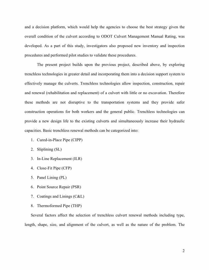
capacities. Basic trenchless renewal methods can be categorized into:
1. Cured-in-Place Pipe (CIPP)
2. Sliplining (SL)
3. In-Line Replacement (ILR)
4. Close-Fit Pipe (CFP)
5. Panel Lining (PL)
6. Point Source Repair (PSR)
7. Coatings and Linings (C&L)
8. Thermoformed Pipe (THP)
Several factors affect the selection of trenchless culvert renewal methods including type,
length, shape, size, and alignment of the culvert, as well as the nature of the problem. The
3
absence of field performance history of these methods further complicates the decision making
procedures.
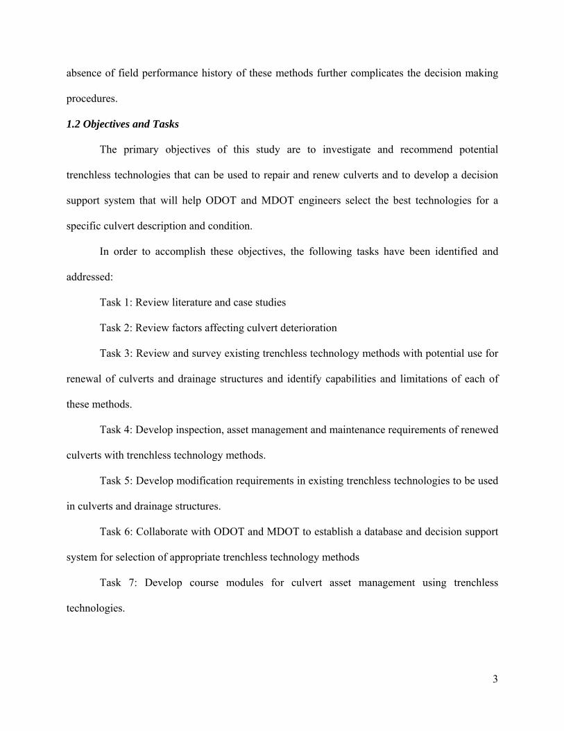
1.2 Objectives and Tasks
The primary objectives of this study are to investigate and recommend potential
trenchless technologies that can be used to repair and renew culverts and to develop a decision
support system that will help ODOT and MDOT engineers select the best technologies for a
specific culvert description and condition.
In order to accomplish these objectives, the following tasks have been identified and
addressed:
Task 1: Review literature and case studies
Task 2: Review factors affecting culvert deterioration
Task 3: Review and survey existing trenchless technology methods with potential use for
renewal of culverts and drainage structures and identify capabilities and limitations of each of
these methods.
Task 4: Develop inspection, asset management and maintenance requirements of renewed
culverts with trenchless technology methods.
Task 5: Develop modification requirements in existing trenchless technologies to be used
in culverts and drainage structures.
Task 6: Collaborate with ODOT and MDOT to establish a database and decision support
system for selection of appropriate trenchless technology methods
Task 7: Develop course modules for culvert asset management using trenchless
technologies.

4
1.3 Outline of the report
Task 1 (review of literature and case studies) is primarily addressed in chapters 2 and 5.
Chapter 2 presents the results of the literature review on the characteristics of culverts and the
factors affecting their performance (task 2). Chapter 3 provides the detailed results of the
national survey of state DOTs which was conducted in order to gain further information
regarding the asset management efforts and their implementation of trenchless technology.
Similarly, chapter 4 presents the results of the survey conducted to gain information from the
technology providers regarding the usage and characteristics of trenchless technology methods.
Trenchless technology methods as presently deployed for inspection, construction, repair and
renewal of buried pipes are examined (task 3) in chapter 5. Task 5, the development of
modification requirements in existing trenchless technologies for application to culverts and
drainage structures, is also addressed in chapter 5. Chapter 6 focuses on the development of asset
management strategies incorporating the trenchless technologies for inspection and renewal
purposes, with current asset management practices for culverts (task 4). A decision support
system designed to help users identify optimum trenchless renewal technology method(s), for
specific culvert characteristics and condition is developed in Chapter 7 (task 6). Based upon the
information and results of the presentation investigation, as described herein, a formal course
module will be prepared to demonstrate culvert asset management using trenchless technologies
(task 7).

5
2. Literature Review
According to the Ohio Department of Transportation’s Culvert Management Manual a
culvert is defined as, “a structure that conveys water or forms a passageway through an
embankment and is designed to support a super-imposed earth load or other fill material plus live
loads” (ODOT 2003) . Therefore a culvert has to both withstand the chemical and physical
deterioration due to effluent and soil characteristics and also carry the earth load due to soil cover
and live loads due to traffic on the roadway at the same time. In this chapter the factors which
affect the deterioration of a culvert are going to be covered and a review of previous publications
related to the culvert performance is going to be presented.
2.1 Factors affecting culvert deterioration
Performance of a culvert is directly proportional to its remaining design service life
which is defined as the period of service without a need for major repairs (AASHTO 1999). For
corrugated metal pipes (CMP), this will normally be the period in years from installation until
deterioration reaches the point of either perforation of any point on the culvert or some specified
percent of metal loss. Service life of a reinforced concrete pipe is the period from its installation
until reinforcing steel is exposed, or a crack signifying severe distress develops. Service life of a
plastic pipe may be considered as the time period until excessive cracking, perforation, or
deflection has occurred.
Culverts require constant maintenance and can deteriorate due to several reasons. A
comprehensive study performed by the Water Research Center (WRc), concludes that the
concept of measuring the rate of deterioration of sewers is unrealistic, and deterioration is more
influenced by random events in a sewer life span. Examples of random events include a heavy
rain storm or a nearby excavation. Distress and collapse of a culvert are the results of the
6
complex interactions of various mechanisms that occur within and around the culvert. The
impact of the deterioration depends upon the culvert size, complexity, topography, and service.
Culvert service life can also be affected by debris damage, erosion (caused by major
storm events), and improper manufacturing or handling of the culvert. Major factors influencing
the performance or service life of a culvert are:
Durability factors:
• Corrosion
• Abrasion
• Erosion
Loss of Structural Integrity:
• Joint Separation
• Misalignment
• Seam Defects
• Seam cracking
• Longitudinal cracks
• Transverse cracks
Environmental Factors:
• Scaling
• Delamination
• Spalling
• Efflorescence
• Honeycombs
• Popouts
7
Hydraulic:
• Insufficient capacity and Flooding
Operational Factors:
• Roots
• Debris blockage
• Maintenance procedures
2.1.1 Durability Factors
Durability is the property to resist erosion, material degradation, and subsequent loss of
function due to environmental and/or other service conditions. Abrasion and corrosion are the
most common durability problems for culverts. Proper attention must be given to these problems
in the design phase. Field inspection of culverts existing on the same stream will prove valuable
in assessing potential problems.
2.1.1.1 Corrosion
Corrosion specifically refers to any process involving the deterioration or degradation of
metal components. Metal culverts or reinforcement in concrete culverts corrode on contact with
water that has a low pH value, acids, bases, salts, oils, and chemicals which act as an electrolyte.
Metal acts as an anode, cathode, and conductor. As electrons move from the anode to the
cathode, metal ions are released into solution, with characteristic pitting at the anode. The culvert
will typically serve as both the anode and the cathode. Similar processes can occur to the cement
in concrete pipe if subjected to highly alkaline soils or to other pipe materials if subjected to
extremely harsh environments. Upon initiation, the corrosion process is self-sustaining, resulting
in the formation of pits at the outer surface of the culvert, with various depths and widths.
Different culvert materials have different characteristics in terms of their reaction to corrosion.

8
For instance, sulfate corrosion is produced as a result of sewer gases, excessive hydraulic flows,
structural failures, leaks and infiltrations, and erosion. Furthermore, bacteria converts the sulfates
to hydrogen sulfides which, when released into the culvert air space, become oxidized to form
sulfuric acid. Sulfuric acid is reactive to some pipe materials leading to corrosion. Severe
corrosion can jeopardize the structural integrity of a culvert and may lead to a collapse.
Corrosion is the process of metals returning to their native state of oxides or salts. Figure
2.1 shows corrosion in a metal culvert. Corrosion of culverts may also occur in the presence of
soils and water containing acids, alkalis, dissolved salts, and organic industrial wastes.
Figure 2.1 Corrosion in Culverts (Najafi et. al. 2008)
The risk of interior corrosion of a culvert depends upon the susceptibility of the culvert
material to corrosion and the amount of corrosive chemicals in the water. Interior culvert
corrosion typically occurs from the formation and release of hydrogen sulfide. Hydrogen sulfide
is formed in anaerobic conditions, such as debris piles, or pools caused by sagging lines. It is
assumed that anaerobic conditions exist in open channel flow at the wetted perimeter, and
therefore, a small amount of hydrogen sulfide is generated and some corrosion can occur if the
conditions allow for release (ASCE, 1994). Hydrogen sulfide gas is released in turbulent
conditions. Such conditions occur at culvert outlets, drop structures greater than 2ft, slope
changes, and during high water velocities.
9
Acidic soils or groundwater attack unprotected cementitious or metal culvert materials.
Stray currents in the ground cause a galvanic corrosion in metal or metal reinforced culverts.
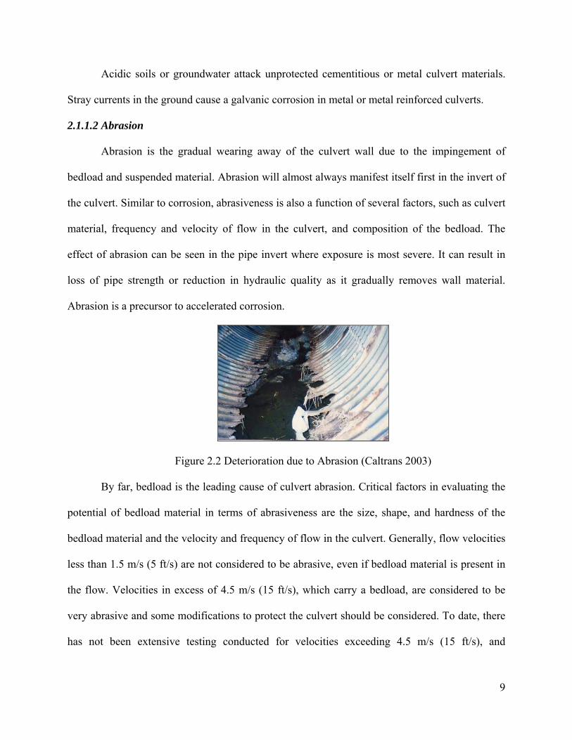
2.1.1.2 Abrasion
Abrasion is the gradual wearing away of the culvert wall due to the impingement of
bedload and suspended material. Abrasion will almost always manifest itself first in the invert of
the culvert. Similar to corrosion, abrasiveness is also a function of several factors, such as culvert
material, frequency and velocity of flow in the culvert, and composition of the bedload. The
effect of abrasion can be seen in the pipe invert where exposure is most severe. It can result in
loss of pipe strength or reduction in hydraulic quality as it gradually removes wall material.
Abrasion is a precursor to accelerated corrosion.
Figure 2.2 Deterioration due to Abrasion (Caltrans 2003)
By far, bedload is the leading cause of culvert abrasion. Critical factors in evaluating the
potential of bedload material in terms of abrasiveness are the size, shape, and hardness of the
bedload material and the velocity and frequency of flow in the culvert. Generally, flow velocities
less than 1.5 m/s (5 ft/s) are not considered to be abrasive, even if bedload material is present in
the flow. Velocities in excess of 4.5 m/s (15 ft/s), which carry a bedload, are considered to be
very abrasive and some modifications to protect the culvert should be considered. To date, there
has not been extensive testing conducted for velocities exceeding 4.5 m/s (15 ft/s), and
10
extrapolation of existing test data to very high velocities is not recommended. Attempts to
compare laboratory testing to field conditions to estimate the effects of bedload abrasion must be
carefully considered. Designers should not use peak flow rate velocities in service life
calculations.
It is very difficult to provide an absolute determination of how a culvert will be affected
from bedload abrasion by just considering its material type. Perhaps the most useful method of
making a reasonable determination is to look at the various types of culvert materials and make
relative comparisons. Tests performed on concrete pipe have generally shown excellent wear
characteristics. Although high-velocity flow will induce abrasion regardless of the size of
bedload particles, tests performed on concrete pipe have shown that cobble and larger sizes (over
75-mm (3-in.) diameter) will induce higher wear rates than sands and gravels. Larger rocks may
cause an impact on the pipe wall which with sufficient power will break away minute particles of
the wall. The use of high-quality aggregate (i.e., aggregate that is harder than the anticipated
bedload hardness) in the concrete mix can greatly enhance the wearability of the concrete.
Likewise, manufacturing methods that lead to a denser concrete mix, such as roller compacted or
spun concrete, or to a higher compressive strength concrete can exhibit increased wearability.
Where velocities are known to be high, and a bedload is present, many entities recommend
additional concrete cover over the reinforcing steel. The presence of a very high or very low pH
environment will accelerate the abrasive effects of any bedload conditions. Steel culverts are the
most susceptible to the dual action of abrasion and corrosion, particularly where thinner walled
pipes are used. Once the thin protective coating on a steel pipe is worn away, whether it is zinc
or other substance, exposure to low resistivity and/or low pH environments can dramatically
shorten the life of a steel culvert. Although aluminum culverts are occasionally specified to

11
combat corrosion, plain aluminum is typically not recommended for abrasive environments since
tests indicate that aluminum can abrade at a rate as much as three times the rate of abrasion of
steel. Abrasive effects are typically countered in metal pipes by the use of:
• Protective coatings,
• Invert paving
• Added metal thickness
• Or a combination of these measures.
Plastic culvert materials (both polyvinyl chloride and high-density polyethylene) exhibit
good abrasion resistance. Since plastic is not subject to corrosion, it does not experience the dual
action of corrosion and abrasion. Plastic pipes, like metal pipes, have relatively thin walls and
thus the rate of wear must be carefully evaluated by measuring the material thickness. The
documented abrasive resisting capabilities of plastic pipe is primarily based upon tests using
small aggregate sizes (gravels and sands) flowing at velocities in the range of 0.6 to 2.1 m/s (2 to
7 ft/s). The effects of large bedload particles (cobbles and larger) and/or high velocity flows are
not well defined due to limited data. Additionally, due to the more recent emergence of
application of plastic pipes as culvert products, specific rehabilitation methods have generally
not been developed yet. Some of the more popular current strategies (e.g., invert paving) are not
effective with plastic pipes due to the difficulty of achieving a satisfactory bond with the smooth
surface of the plastic pipes.
2.1.1.3 Erosion
Erosion or scour at culvert ends can occur due to inadequate energy dissipation,
headcutting that reaches a culvert, improper entrance or exit alignment and design, high
watertable (above culvert level), frequent and high magnitude of hydraulic surcharge, and soil

12
types (silts, silty fine sands, and fine sands). Regardless of the cause, the removal of structural
backfill from around the culvert eliminates the ability of the pipe to support loading. Loss of side
support will allow the sides of the culvert to move outward when loaded vertically, and collapse
will likely occur once the culvert deformation exceeds 10 percent. Uneven loading of culverts
because of joint displacement also accelerates the pipe deterioration process. Erosive effects at
culvert ends or the erosive effects of piping may lead to the ultimate failure of the culvert
therefore precautionary measures should be taken as a part of routine design practice.
Erosion may also take place if a defined approach channel is not aligned with the culvert
axis. If the culvert is not aligned with the channel and the channel is modified to bend into the
culvert, erosion can occur at the bend in the channel. Erosion of the embankment at inlet may be
reduced by constructing the culvert into the fill slope and retaining the fill by headwall and
wingwalls. Good compaction of backfill material is essential to reduce the possibility of erosion.
Where soils are fairly erosive, special impervious bedding and backfill materials should be
placed for a short distance at the culvert entrance. Scouring is a problem that can be encountered
at the culvert outlet. Local scour is the result of high-velocity flow at the culvert outlet, but its
effect extends only a limited distance downstream as the velocity transitions to outlet channel
conditions. Long, smooth-barrel culverts on steep slopes will produce the highest velocities
causing highest erosion at outlet. A common mitigation measure for small culverts is to provide
riprap aprons. If the flow velocity is very high and is not controllable by riprap aprons then
energy dissipaters should be provided.
2.1.2 Loss of Structural Integrity
Although generally unpredictable from a design standpoint, there are other physical
factors besides corrosion and abrasion that can shorten the life of drainage culverts. The loss of
13
structural integrity can sometimes be traced to a defect in the manufacturing process of the pipe,
improper construction techniques or the effects of a large storm event. More commonly, though,
the loss of structural integrity occurs over several years and is related to such factors as piping,
seepage, soil movement, scour, and backfill soil loss. These processes can gradually reduce the
culvert strength and make it susceptible to catastrophic events such as floods. The agencies are
unable to predict when or how a particular drainage facility might be affected by one of these
factors. Therefore, it is important to establish a program of routine inspections to identify the
progression of a problem before damage to the roadway occurs.
Structural deterioration is hypothesized to be influenced by a set of installation and
construction factors, including pipe design, pipe size, buried depth, and site factors such as soil
type, moisture index and tree root intrusion (Tran et al. 2006). Structural defect failure
mechanisms include cracks and fractures in the pipeline material that are caused by a change in
the forces around a pipeline or a change in the ability of the pipe material to resist existing
forces. The infiltration of groundwater through existing structural defects creates voids or
increases the size of existing voids as the infiltrating water carries particles from the soil into the
pipeline. The weakening of the soil makes the strata above the pipe vulnerable to surface
collapse. The effects of infiltration on void formation are made worse by the process of
exfiltration. Exfiltration occurs when water leaves the pipeline through structural defects during
periods of hydraulic surcharge. Surcharge waste water can scour or loosen more fine material at
the perimeter of the voids.
Common defects found in any culvert type are going to be discussed in the following
sections:
2.1.2.1 Joint Separation

14
Allowable joint separation depends upon the type of joint being used. Joints with an
external sleeve (as used for most corrugated metal pipes and corrugated high-density
polyethylene) can allow a limited amount of axial separation between abutted pipe ends since the
external sleeve will typically maintain joint integrity and limit infiltration/ exfiltration. For bell-
and-spigot-type joints, there is no allowable separation; instead, some minimum amount of
overlap at the joint corresponding depending on the pipe diameter is usually specified. This
minimum amount of overlap at the joint becomes particularly important for pipes installed on a
curved alignment. While the portion of the pipe joint on the inside of the curve may have no
problem with meeting the minimum overlap, most specifications will call special attention to that
portion of the pipe on the outside of the curve and require specially manufactured curved or
angled pipe sections if the minimum overlap cannot be attained. There can be numerous causes
of joint separation or insufficient overlap, with the most common being inadequate quality
control during construction. Construction related problems can be due to uneven bedding,
uneven or poorly compacted backfilling material, or unexpected settlement. Joint problems are
also common when culverts are installed under existing roadways by constructing half the width
at a time. This usually is accomplished by closing half of the roadway width while the other half
is still open to traffic. The half section is then constructed in an open trench operation. The same
procedure is then repeated on the other half of the roadway. Adequate backfill compaction and
alignment at the point where the two halves meet is very difficult and proper joining may not
occur. In addition to problems related to construction, natural forces can lead to joint separation
and/or inadequate overlap. Earthquakes and landslides can easily shift culvert positions as can
frost heave. Pipes laid on steep slopes, particularly downdrains that are often laid on the surface
of the slope, are subject to joint separation. Anchorage and/or higher strength joint connections
15
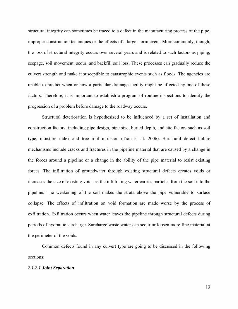
are often specified. Culverts should be inspected for movement after any major natural event that
could result in a shifting of culvert position.
Figure 2.3 Culvert Pipe showing Cracks and Joint Separation (Najafi et. al 2008)
The main function of culvert joints is to provide connections between pipe segments that
are watertight, durable, and resistant to root intrusion. Joint failures are due to leaks where pipe
joints become separated or rubber ring is improperly sealed. Joint type is an important issue since
the type of joint will influence the susceptibility of the pipe to specific failures. A large portion
of joint problems may be related to the amount of flexibility and lateral constraint the joint
provides, as well as the culvert joint’s actual strength and its ability to resist corrosion.
2.1.2.2 Misalignment
Almost all of the problems that cause joint separation can also lead to misalignment.
Minor deviations from the planned alignment are typically not harmful. Minor amounts of
deflection (or pull) at successive joints are occasionally planned in the design to create a curve in
the alignment. Segmental construction, where portions of a single pipe run are constructed at
separate times, will often lead to misalignment due to differing settlement rates and the difficulty
in maintaining constant grade through the area of segment connection. For these reasons, it is
generally preferable to construct an entire run of pipe in a single sequence.
2.1.2.3 Seam Defects

16
Seam defects are the result of poor manufacturing or improper handling. Defects of this
type are typically realized prior to installation but, if undetected, may lead to culvert failure.
Proper inspection during the construction phase, and obtaining pipe material specifications, are
necessary to limit these potential problems.
The longitudinal seams in steel structures are bolted with high strength bolts in crests and
valleys of the corrugations. These are bearing type connections and are not dependent on the
minimum clamping force of bolt tension to develop interface friction between the plates.
Fasteners must be checked for their tightness, as any loose or missing fasteners may lead to
collapse of the structure. The lapped and bolted longitudinal seams affect the shape and
curvature of the structure. Improper erection or fabrication can result in cocked or cusped seams.
Cusped seams alter the structure’s shape, appearance, and dimensions from the original design.
A cocked seam can result in loss of backfill and may reduce the ultimate ring compression
strength of the seam.
2.1.2.4 Seam Cracking
This type of defect is developed along the boltholes of longitudinal seams. As cracking
progresses, the structure may lose ring compression capability of the seam and this could result
in deformation of the culvert or possible failure. Longitudinal cracks are dangerous when
accompanied by significant deflection, distortion, and other conditions indicative of backfill or
soil problems. Cracking may be caused by improper erection practices such as using bolting
force to lay down a badly cocked seam.
Bolted seams develop their ultimate strength under compression. Bolt tipping occurs
when the plates slip. As the plates begin to slip, the bolt shank plastically elongates the bolts tip,

17
and the boltholes. Excessive compression on a seam could result in plate deformations around
the tipped bolts and failure is reached when the bolts are pulled through the plates.
Pipe wall damages such as dents, bulges, creases, and cracks are found when the defects
are extensive. They impair the integrity of the barrel in ring compression or permit infiltration of
backfill. When the deformation type damages are critical, they result in distorted cross-sectional
shapes.
2.1.2.5 Longitudinal Cracks
Concrete is strong in compression and weak in tension. Reinforcing steel is provided to
handle the tensile stresses. Hairline longitudinal cracks in the crown or invert indicate that steel
has received part of the load. Longitudinal cracking in excess of 0.1 inch in width may indicate
overloading or poor bedding. If the pipe is placed on hard material and backfill is not adequately
compacted around the pipe or under the haunches of the pipe, loads will be concentrated along
the bottom of the pipe and may result in flexure or shear cracking as shown in the Figure 2.4.
Figure 2.4 Longitudinal Crack in a Culvert Pipe
(Source: National Research Council Canada, 2006)
2.1.2.6 Transverse Cracks
Poor bedding, as shown in Figure 2.5, causes transverse cracks or circumferential cracks.
Cracks occur across the bottom or crown of the pipe when it is supported at the ends of each
section. This is the result of poor installation practices, such as failing to provide sufficient depth
of suitable bedding material.

18
Figure 2.5 Transverse Cracks in a Culvert Pipe (Najafi et. al. 2008)
2.1.3 Environmental Factors (Caltrans 2003)
2.1.3.1 Scaling
Scaling is the gradual and continuing loss of aggregate over an area due to the chemical
breakdown of the cement bond. It starts as a localized small patch, which merges and extends to
expose large areas. Light scaling does not expose the coarse aggregate whereas moderate scaling
exposes coarse aggregate and may involve loss up to 1/8 to 3/8 inch of the surface mortar. In
severe scaling, more surfaces will be lost (NRMCA 1998).
Figure 2.6 Scaling exposed on Concrete Surface.
(Source: Photomac Construction industries 2008)
2.1.3.2 Delamination
Delamination is the sub surface separation of concrete into layers. It is caused by
corrosion and internal expansion. The extent of deterioration in delamination is often unknown
until the delamination is opened up.

19
Figure 2.7 Delamination on a Concrete Surface.
(Source: Concrete Restoration and Construction 2007)
2.1.3.3 Spalling
Spalling is a depression in concrete caused by a separation of a portion of the surface
concrete where the topping is popping or peeling off. This is due to the action of weak top
surface, overworking of the concrete, low entrainment, excessive water, and freeze thaw cycling.
Figure 2.8 Spalling on a Concrete Surface.
(Source: Caltrans 2003)
2.1.3.4 Efflorescence
Efflorescence is a combination of calcium carbonate leached out of the cement paste and
other recrystallized carbonate and chloride compounds. It is a white crystalline or powdery
deposit on the surface of the concrete surface and is caused by water seeping through the culvert
wall. The water dissolves salts inside the concrete surface, while moving through it, and then
evaporates leaving the salts on the surface. Figure 2.9 shows efflorescence of the concrete
surface.

20
Figure 2.9 Formation of Efflorescence on a Concrete Surface.
(Source: House Check 2007)
2.1.3.5 Honeycombs
Honeycombs (Figure 2.10) are coarse aggregates on the surface without any mortar
covering or surrounding the aggregate particles. The honeycombing may extend deep inside the
concrete and are caused by a poorly graded concrete mix or by insufficient vibration at the time
of placement. Honeycombing must be repaired when noticed to prevent further deterioration of
the concrete surface.
Figure 2.10 Honeycombing on a concrete surface.
(Source: Department of Architectural Engineering 2006)
2.1.3.6 Popouts
Popouts are conical fragments that break out of the surface of the concrete leaving small
holes as shown in Figure 2.11. Popouts occur because the concrete has been overworked,
allowing the aggregates to drift upward toward the surface.

21
Figure 2.11 Pop-outs in a Concrete Structure.
(Source: Concrete Sealers, Specialty Coatings and Consulting 2006)
2.1.4 Hydraulic Factors
When the performance of a culvert is reduced due to hydraulic factors, safety of the
commuters, financial condition of the agency, and environment may be affected adversely. These
impacts can be due to the flooding of adjacent properties or downstream areas from unexpected
headwater depths. An inadequate hydraulic performance of a culvert may also damage the
embankment or culvert because of erosion (FHWA 1986). Hydraulic factors that deteriorate
culverts include but are not limited to the following:
2.1.4.1 Insufficient Capacity and Flooding
Flooding can cause overtopping of the roadway and, in extreme cases, failure of the
culvert and the roadway above. In addition, flooding can damage property adjacent to the
structure as well as property both upstream and downstream of the culvert. Flooding will cause
incurrence of costs to the agency, the motorists, and to the owners of adjacent properties (FHWA
1986). Flooding of major urban or rural areas can be caused by insufficient culvert capacity.
Insufficient capacity may result from faulty designs, debris blockage, etc. In a recent case (June
19th, 2008) covered by the Daily Courier (Connellsville, PA), a backed-up culvert ditch
overflowed during two sudden, heavy rainfalls. It was reported that the culvert which traveled
under a road, railroad tracks and into the river, was blocked by an illegally dumped tire.
2.1.5 Operational Factors

22
The failure mechanism due to operational defects originates from an increase in demand
and a decrease in capacity. Infiltration and inflow are the two types of demand on a pipe system.
Infiltration increases the demand as the number of structural defects grows. Inflow is the demand
on the system from service connections or storm waters or both (ASCE 1994; EPA 1991). A
decrease in capacity is the result of a decrease in the effective diameter of the pipeline and an
increase in the roughness coefficient. The effective diameter is reduced by structural defects such
as open and offset joints, broken pipe sections, root masses, grease, or collected debris.
2.1.5.1 Debris Blockage
Debris carried by stormwater can be a destructive element for culverts. However, this
destructive potential is primarily related to clogging of the culvert with the accompanying effects
of overtopping and erosion or a single impact from a large piece of debris that causes immediate
damage to the culvert. Large volumes of debris can, however, add to the effects of bedload
abrasion. The potential for debris to cause abrasion will depend primarily upon the relative
hardness of the debris and the culvert material. The most common types of debris that lead to
major damage are boulders, trees and shrubs, and ice although, during major storm events,
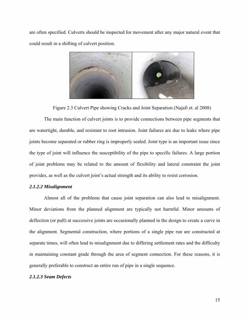
anything movable by storm water can be transported to culvert locations. Figure 2.12 shows the
debris accumulated in a culvert. Types of areas that have proven troublesome are drainage areas
with unstable hillsides, heavily forested areas subject to fire, streams that support beaver
activities, and cold weather sites where ice accumulation can block or otherwise damage
drainage structures. Whenever debris is likely to pose a problem, appropriate debris control
structures should be considered for installation.
23
Figure 2.12 Debris at the Opening of the Culvert (Najafi et. al. 2008)
The countermeasures that mitigate the effects of debris on culverts were examined and
published by the Federal Highway Association (2005). Structural measures to mitigate debris
blockage in culverts are:
• Debris Deflectors
• Debris Racks
• Debris Risers
• Debris Cribs
• Debris Fins
• Debris Dams and Basins
• Or a combination of two or more devices
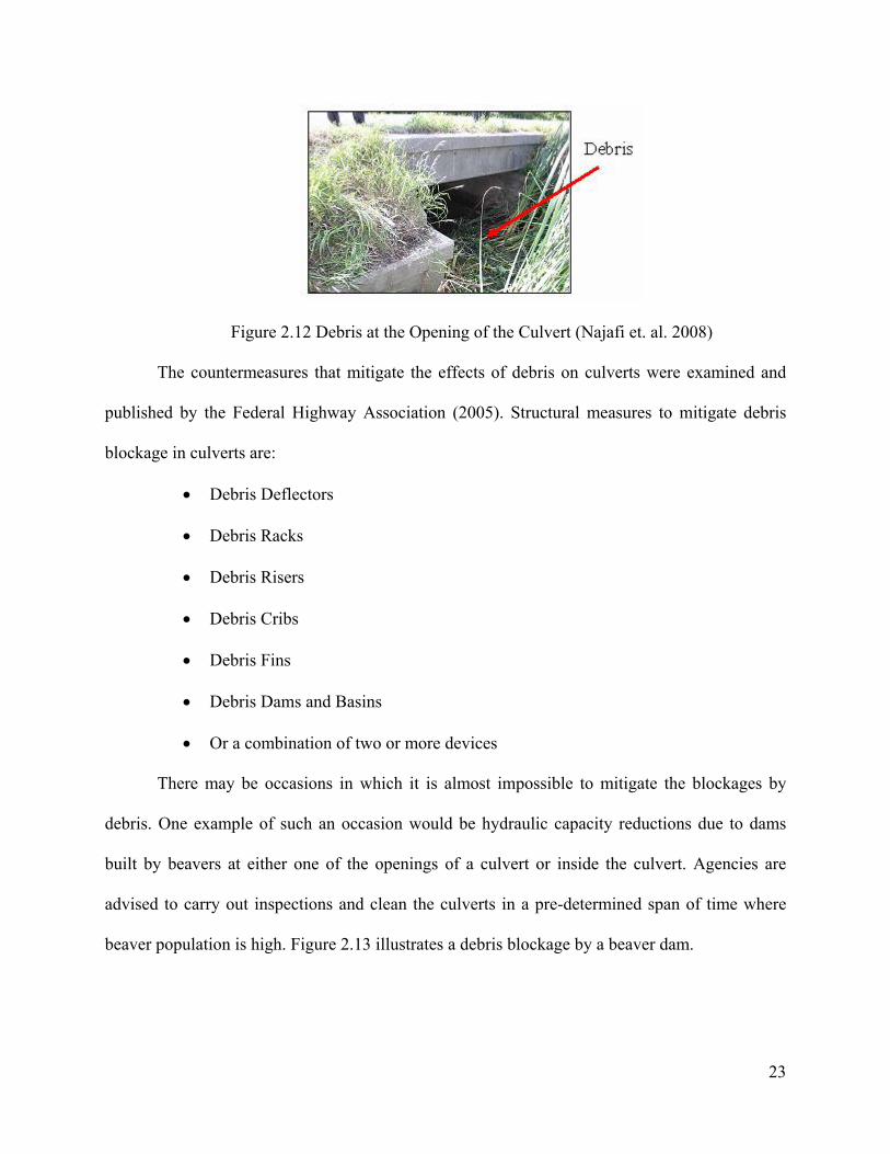
There may be occasions in which it is almost impossible to mitigate the blockages by
debris. One example of such an occasion would be hydraulic capacity reductions due to dams
built by beavers at either one of the openings of a culvert or inside the culvert. Agencies are
advised to carry out inspections and clean the culverts in a pre-determined span of time where
beaver population is high. Figure 2.13 illustrates a debris blockage by a beaver dam.
24
Figure 2.13 Beaver Dam inside a Culvert (Patenaude 2003)
2.1.6 Other Factors
Other factors which influence the performance or service life of a culvert are as follows:
(Information provided in this section is excerpted from “Trenchless Technologies” (Najafi
2004)).
Culvert Size
Several authors have investigated the relationship between pipe size and structural
stability. Studies indicate that there is a decreasing trend in pipe failure rate with increasing
diameter and this trend is directly attributed to the increasing wall thickness and joint reliability
with increase in pipe diameter. Larger wall thickness provides the pipe with better structural
integrity and improved resistance to corrosion failures.
Although longitudinal bending stresses increase with increasing pipe diameter, the rate is
slower than the increase in pipe’s section modulus, hence pipes, which have high length-to-
diameter ratios, are more likely to suffer from excessive bending stresses. Despite the fact that
the above issue is well documented within the literature, there is little evidence of any numerical
or statistical investigation of the effect of high pipe length-to-diameter ratios in regard to the mod
of failure.
25
Culvert Gradient
The slope of a gravity pipe is found to have an impact on the condition of the pipe. Under
same conditions, a pipe with a steeper slope has a higher risk in terms of deterioration of its
segments. The probable reason of this situation is due to the fact that steeper pipe segments cause
faster flow rates, resulting in greater risk for abrasion, erosion and surface wear on the inside
walls, invert sections or joints of pipe segments. Generation of deteriorating gases or movement
of debris may also increase deterioration rates.
Culvert Depth
While investigating the effect of depth on structural condition of pipes, it was found that
defect rate steadily decreases up to a depth of 18 ft, below which the defect rate begins
increasing with depth. It was suggested that the first pattern probably reflected the decreasing
influence of surface factors such as road traffic and utility or surface maintenance activity. The
second occurrence or pattern was explained by the increasing effect of overburden pressure.
Jones (1984) has suggested that, in shallow pipes, the effect of seasonal moisture variations in
the soil surrounding might be significant. In an analysis of over 4400 pipe failures, Anderson and
Cullen (1982) reported that 65 percent of all incidents occurred at a depth of 6.5 ft or less and 25
percent from 6.5 to 13 ft deep, although no indication of overall pipe depth distribution is
provided. Changes in cover depth may also be important in determining a pipe’s structural
stability. (Najafi 2004)
Frost Heave
Frost heave is defined as the vertical expansion of soil caused by soil freezing and ice
lens formation. All underground structures require the consideration of frost heave effects due to
possible displacement of portions of the entire underground structure.
26
Differential heave causes sections of pipe to experience non-uniform displacements, and
this situation may result in strong flexural stress. Uniform heaving may also prove to be a
problem under certain circumstances where pipe joints are not subject to movement. Under this
scenario, the pipe experiences stresses similar to a simple beam loading, in which the pipe will
experience bending stresses. Failure of pipe joints may occur as a result of the frost heave
process. This may be a function of the type of connection and the type of fill material used
between joints.
The conditions for frost heave require the presence of a frost-susceptible soil, the
presence of a sufficient water source, and a ground temperature below the freezing point.
With all of the above factors present, there is a potential for damage due to frost heave. The
tendency of a soil to be affected by frost heave under freezing conditions is affected by
properties such as grain size, rate of freezing, the availability of water, and by applied loads.
Frost Load
The failure of pipes during winter could be attributed to frost load which presents an
increased earth load on the buried pipes. In a trench, the frost load develops primarily as a
consequence of different frost susceptibilities of the backfill and the sidewalls of the trench and
the interaction at the trench backfill-sidewall interface. Trench width, differences in frost
susceptibilities of backfill and trench sidewall materials, stiffness of the medium below the
freezing front, and shear stiffness and backfill-sidewall interface play important roles in the
generation of frost loads. Thus, it is preferable to use a backfill material that has equal or lower
frost susceptibility than that of the sidewall in order to minimize the development of excessive
differential frost loads.
Soil-culvert Interaction
27
Soil-culvert interaction is among the possible causes of pipe deterioration. The resistance
of the soil-to-pipe union is important because the shear strength of the interaction can affect the
degree of mobility of the pipeline and hence its ability to displace. In cold temperatures, the bond
between the soil and pipe restrains the pipe to shrink axially. A high soil-pipeline interaction will
not allow the pipe to contract, and consequently the axial stress in the pipe will increase. A
strong bond between an iron pipe and soil may cause excessive soil-pipe interface shear which
may result in the abrasion of the pipe coating. This abrasion may lead to premature corrosion of
the pipe exterior.
Pipe Wall Temperature Gradients
For longitudinal failures, a failure mechanism might be formed when a high temperature
gradient occurs across the pipe wall. This temperature gradient can lead to unusually high hoop
stresses and subsequently cause failure.
Differential culvert temperature
Some sources in literature speculate that a high differential temperature between the
internal and external pipe wall can produce high temperature gradients. Under such conditions
the inner and outer fibers will be subject to different temperature drops, resulting in differential
strains and circumferential stresses.
Soil Type
The significance of the type of soil cannot be overlooked, as it is one of the most
important factors, having effects on almost all of the above mechanisms. Its effects on frost
heave, strength of soil-pipeline interaction, and external corrosion can be important for many
failure mechanisms.
28
The type of soil the pipe is located in is also important in terms of differential heaving
and thaw settlement. It has been shown that if a pipe is located at the interface of two different
soil types, each type of soil will experience an uneven amount of frost heaving, and therefore
have an influence on the amount of strain experienced by the pipe. In the same manner, thaw
settlement will lead to differential stress distributions on the pipeline.
Soil corrosivity is a soil characteristic that must be considered for external corrosion
predictions. Physical characteristics (particle size, friability, uniformity, organic content, color,
etc.) may reflect corrosivity, based on observations and testing. Soil uniformity is important
because of the possible development of localized corrosion cells. Corrosion cells may be caused
by a difference in potential between unlike soil types, with both soils being in contact with the
pipe. If the approximate uniformity coefficient for a particular soil class can be estimated, then
the possibility of corrosion can also be estimated.
Groundwater Level
Soil water content is an important parameter in several aspects. As mentioned earlier, the
rate of frost heave is controlled by the availability of free water. This parameter is also important
in terms of external corrosion.
From the perspective of external corrosion, soil corrosion aggressiveness has been related
to moisture content. Soils with moisture content above 20 percent are considered to be
particularly corrosive (Jarvis and Hedges 1994). Studies substantiate that moisture content is a
factor contributing to soil aggressiveness.
Overburden Pressure
Overburden pressure is considered to be important because of its ability to help
characterize frost heaving and soil-pipeline resistance. It can be characterized by the depth of
29
cover and soil density. Literature indicates that the overburden pressure is important for the rate
of heaving.
From the perspective of soil-pipeline interaction, it has been demonstrated that the
frictional soil resistance is affected by pipe diameter and depth (Rajani et al. 1995). Also, from
the perspective of failure modes, larger pipes are more susceptible to crushing type of failure
than smaller pipes. This is due to depth, or the external loadings (i.e., roadways, large structures,
and the like) to which the pipe is subjected (O’Day 1982).
Temperature
The effects of temperature on pipe breakage rates have been observed and reported by
many researchers. Newport (1981) analyzed circumferential pipe breakage data and found that
increased breakage rates coincided with cumulative degree-frost (usually referred to as freezing
index in North America and expressed as degree-days) in the winter as well as with very dry
weather in the summer. Newport attributed the increase in winter breakage rates to the increase
in earth loads because of frost penetration, that is, frost loads, and the summer breakage rates to
the increase in shear stress exerted on the pipe by soil shrinkage in a dry summer. Newport also
observed that when two consecutive cold periods occurred, the breakage rates (in terms of breaks
per degree-frost) in the first one exceeded those of the second one and rationalized that the early
frost purged the system of its weakest pipes, causing the later frost to encounter a more robust
system.
Precipitation (Snow or Rain)
Snow cover is indicative of the insulating effect on ground temperature, as the snow
allows for the entrapment of heat into the ground. The amount of rainfall coupled with the soil
type may be indicative of moisture content or hydraulic conductivity if these parameters are not
30
measured regularly. Some literature indicates that corrosion resistance is enhanced during dry
periods of the year (Smith 1968). Therefore, inclusion of this parameter may be necessary to help
characterize climatic changes as well as to infer adjustments to soil parameters.
Hydrogen Ion Concentration (pH)
In order to characterize external corrosion, it is necessary to find parameters which
indicate the corrosivity of the soil. Soil pH is a good indicator of external corrosion because
certain pH ranges allow for different corrosion mechanisms to occur. It has also been found that
resistivity is a function of pH. For that reason, only one of the two may be required for
characterization.
pH is a measure of the acidity or alkalinity of a solution. Generally soil or water pH
levels between 5.5 and 8.5 are not harmful. The water is acidic if the pH is less than 5.5 and
alkaline when pH is greater than 8.5 Presence of oxygen at the metal surface is necessary for
corrosion to occur. The lowest pH levels (most acidic) are typically seen in areas that have
received high rainfall over many centuries. The runoff and percolation will leach the soluble
salts, with the resultant soil becoming acidic. Milder acids can be found in runoff from marshy
areas, which contain humeric acid, and mountain runoff that often contains carbonic acid.
Conversely, arid areas are much more likely to be alkaline due to soluble salts contained in
groundwater.
Soil Resistivity
Resistivity of soil is a measure of the soil’s ability to conduct electrical current. It is
affected primarily by the nature, concentration of dissolved salts, temperature, moisture content,
compactness, and the presence of inert materials such as stones and gravel. The greater the
resistivity of the soil, the less capable the soil is of conducting electricity and thus, the corrosion
31
potential is lower. The measurement unit for resistivity is ohm-centimeters or, more precisely,
the electrical resistance between opposite faces of a one-centimeter cube. Resistivity values in
excess of about 5000 ohm-cm are considered to present limited corrosion potential. Soils with
resistivity values below the range of 1000 to 3000 ohm-cm will usually require some level of
pipe protection, depending on the corresponding pH level (e.g., if pH < 5.0, enhanced pipe
protection may be needed for resistivity values below 3000 ohm-cm; if pH > 6.5, enhanced pipe
protection may not be needed unless resistivity values are below 1500). As a comparative
measure, resistivity of seawater is in the range of 25 ohm-cm, clay soils’ resistivity range from
approximately 750 to 2000 ohm-cm, and loams’ resistivity range from 3000 to 10000 ohm-cm.
Soils that are of a more granular nature exhibit even higher resistivity values. Some entities use
the reciprocal of resistivity, conductivity, as the criterion for corrosive potential.
Corrosion can be induced by electric current in the proximity of the pipe. Metal pipes are
affected most often; however reinforcing steel in concrete pipe may also suffer an increased rate
of corrosion. Typical sources of stray current are electrified rail lines, high tension electric
transmission lines, and cathodically protected structures (gas transmission mains). Protective
coatings are usually applied to the pipe to negate the effects of stray electric currents.
Chlorides
Dissolved salts containing chloride ions can be present in the soil or water surrounding a
culvert. Chlorides are also of concern at coastal locations or near brackish water sources.
Dissolved salts can enhance culvert durability if their presence decreases oxygen solubility but,
in most instances, corrosive potential is increased as the negative chloride ion decreases the
resistivity of the soil and/or water and destroys the protective film on anodic areas. Chlorides, as
with most of the more common corrosive elements, primarily attack unprotected metal culverts
32
and the reinforcing steel in concrete culverts if concrete cover is inadequate, cracked, or highly
permeable.
Sulfates
Sulfates can occur naturally or may be a product of human activities, most notably mine
wastes. Sulfates, in the form of hydrogen sulfide, can also be created from biological activity,
which is more common in wastewater or sanitary sewers, and can combine with oxygen and
water to form sulfuric acid. Although high concentrations can lower pH and be of concern to
metal culverts, sulfates are typically more damaging to concrete. Typically, the sulfate in one or
more various forms combines with the lime in cement to form calcium sulfate, which is
structurally weak. Concrete pipe is normally sufficient to withstand sulfate concentrations of
1000 parts per million (ppm) or less. For higher concentrations of sulfates, higher strength
concrete, concrete with lower amounts of calcium aluminate (under 5 percent) or special coatings
may be necessary.
Industrial Effluents
Industrial effluents may contain compounds that are extremely destructive to pipe
materials. Waste streams from most industries are sufficiently regulated therefore raise limited
concern to the highway engineer. However, tailings from mining operations, livestock operations
or illegal connections from residential or small commercial lots can be a source of highly acidic
runoff. Potentially corrosive runoff can also be of concern at locations known for a high
probability of accidental spills (e.g., runaway truck escape ramps). An assessment of the
constituents and their possible concentrations in the streamflow should be performed whenever
industrial effluents are suspected. If the source can be identified, corrective action can usually be
taken.

33
2.2 Modes of Culvert Deterioration
As explained at the beginning of the chapter, culvert deterioration is a complex process;
which is affected by many factors such as structural failure, hydraulic factors, environmental
factors, functional factors, age of the pipe, quality of initial construction, etc. The intensity of
structural failures depends on the size of the defect, soil type, interior hydraulic regime,
groundwater level and fluctuation, corrosion, method of construction, and loading on the pipe.
Figure 2.14 illustrates various kinds of internal and external forces acting on a pipe. The modes
of failure depend on the type of environment and pipeline material.
Figure 2.14 Pipeline and Culvert interactions leading to failure (O’Day et al., 1986)
Culvert breakage is likely to occur on pipes whose structural integrity has been
compromised by corrosion, degradation, inadequate installation, or manufacturing defects.
A classical survival function relating the age of the pipeline to the failure rate is denoted
by a bathtub curve as shown in Figure 2.15. The early part of the curve shows infantile failure
which is representative of failure due to human factors in the actual laying of the pipe
(manufacturing faults, tend to appear during that part). It is commonly assumed that the older the
pipes, the poorer the pipe condition; however, this is not always the case and young pipes
collapse, resulting in a reduced level of serviceability (Trans et al, 2006). A period of the time

34
follows in which failure rate is generally low. When failure does occur it may depend on many
factors, such as presence of excessive loads for which the structure is no originally designed for,
or settlement. As the pipes tend toward the end of their useful life the failure rate increases
exponentially. This classic survival profile is known as the bathtub curve. The bathtub curve can
be applied to an individual pipe, a group of pipes with similar characteristics, or the whole
population of a pipe network.
Figure 2.15 Bathtub curve of a pipe and culvert performance with age. (Najafi 2004)
2.3 Previous Research on Culvert Performance
Culvert durability and various factors affecting culvert performance have been focus
points of researchers for a long time. Several culvert types have been examined under several
different environmental conditions. These publications offer very important information in order
to understand the behavior of culverts. In this section of the report culverts are going to be

35
divided into 4 different groups according to their material types and some of the important
publications will be addressed in each group.
2.3.1 Corrugated Metal Culverts
Corrugated metal culverts have been in service for more than 60 years in the United States.
Long range of selection for thickness and size and the ability of modification to increase the
durability made this material preferable for many sites. George W. Ring has cited a letter written
by Kent Allemeier in his paper “Culvert Durability: Where are we?” in 1984. According to
Allemeier, the following are the advantages of Corrugated Steel Pipes:
• They are ideal for shipping due to their lightweight.
• Their sizes and shapes vary in a large range.
• The thickness of the sheets and also the corrugations can be selected from a wide range in
order to obtain the required strength.
• Easy for the working crew to assemble and install.
Allemeier also mentioned the disadvantages of the Corrugated Steel Pipes as follows:
• Corrugation roughness decreases the rate of flow except for the smooth-lines pipes.
• Due to presence of sand and/or rock in a high velocity stream, abrasion may cause loss of
metal.
• High sensitivity to high or low soil pH or water pH, and soil or water resistivity, which
may end up with corrosion.
• Backfill operations must be handled with care due to the importance of soil support for
load bearing.
According to Bednar (1989) the most important factors affecting the durability of
galvanized steel pipes are the pH, dissolved salts, hardness, alkalinity, abrasiveness and time of

36
water contact. The rate of corrosion is affected negatively as the difference between acidity and
chloride/sulfate salts and hardness and alkalinity salts increases and with the presence of
abrasion. The author also adds that usually the rate of waterside corrosion is more rapid than the
soil side corrosion therefore controlling factor is water side corrosion but not the soil side
corrosion.
The disadvantages of corrugated metal pipes due to their sensitivity to abrasion and
corrosion have been recognized by the transportation authorities and therefore several different
protective coatings have been applied to the invert sections of the corrugated metal pipes where
abrasion and corrosion was considered as a problem. Some of the studies investigating the
durability and structural problems of corrugated metal culverts and the coating types are
discussed in the following section:
One of the most thorough studies related to the durability of culverts is the “Ohio Culvert
Durability” (Meacham et. al., 1982). In this particular project, 1616 culverts, which consisted of
reinforced concrete pipes and galvanized corrugated steel pipes, were inspected in total. The total
number of inspected culverts, 1616, corresponds to twenty percent of the total number of culverts
with a diameter of 42” and higher gathered in the inventory database created in 1971. According
to the predetermined breakdown of structures to be inspected, 67% of the 1616 culverts were
metal and 33% concrete. Percentage of the metal culverts was higher than the percentage of the
concrete culverts due to their higher variety. Corrugated metal culverts involved structural plate
pipes and corrugated metal pipes. Selection of the culverts to be inspected also involved an age
criteria, making the sample equally divided between 10 years of intervals. Following table (Table
2.1) was given to summarize the total number of the culverts in the inventory and the number of
culverts inspected:

37
Material Type Inventory Inspected % Inspected Concrete 4170 545 13
Corrugated Metal 2193 685 31 Sectional Plate 1600 386 24
Total 7963 1616 20 Table 2.1: Breakdown of culverts inspected by Meacham et. al. (1982)
A visual rating system was used in order to evaluate the conditions of the culverts.
According to this system 5 different classifications namely, excellent, very good, good, fair and
poor, were used.
According to the statistical analysis authors conducted, the most important factor
affecting the metal culvert rating was determined as the age of the culvert, which was defined as
the time in years that the metal itself was exposed to the flow. Other significant parameters were
determined as the pH of the water and abrasion. The acidity of the flow was shown to have a
negative impact on the culvert condition. Abrasion was found to be detrimental for the flows
with high pH flows. Four different equations were provided relating these significant variables to
the metal loss for corrugated metal pipes with and without abrasion and for structural plates with
and without abrasion respectively. Those equations yielded R-squared values in the range of
0.694 to 0.815.
Conventional Bituminous Protection was also analyzed in this study. Bituminous
protection was divided into two groups: First group was the bituminous coating; second group
was the bituminous coating with paved inverts. For the bituminous coating age was found to be
the only factor with a statistically significant effect. The correlation between the age and
protection rating was too low to reach to a conclusion about the service life of the protection.
Therefore authors followed another strategy, which involved performing regression analysis to
the protection rating and the percent of culverts rated as “not poor”. This strategy yielded a good
correlation and the service life was estimated as 3.16 years. For the bituminous coating with

38
paved invert type of protection, age (very large negative effect), sum of sediment depth and flow
depth (large negative effect) and abrasion (minor negative effect) was shown to have statistically
significant effects. Correlation coefficient was found to be somewhat larger than the bituminous
coating but still it was not satisfactory to reach a conclusion about the service life. The same
strategy was used for the bituminous coating with paved invert type of protection and this
strategy yielded 25 years of service life for the case where dry weather flow was within the
paved section and 12 years of service life where dry weather flow overtopped the paved portion.
Authors highlighted the difference between these two values and reached to the conclusion that
the level of dry weather flow played a very important role on the service life of this particular
protection.
A similar study is recently completed in May 2005 by Ohio Research Institute for
Transportation and Environment (Mitchell et. al., 2005). In this study authors inspected a total
number of 60 culverts with the objectives of verifying and modifying the inspection procedures
of Ohio Culvert Management Manual and determining the significant parameters for culvert
durability. The breakdown of these 60 culverts was determined as 25 concrete culverts, 25 metal
culverts and 10 thermoplastic culverts. Some of the characteristics of the 25 metal culverts are
given in Table 2.2
Description Reading Characteristics 7 out of 25 Pipe-arch
Shape 18 out of 25 Circular 14 out of 25 25 to 50 years old 3 out of 25 50 to 75 years old Age 8 out of 25 Unknown 7 out of 25 2 to 5 ft. 14 out of 25 5 to 8 ft. span Span 4 out of 25 Larger than 8 ft span
11 out of 25 0 to 5 ft Soil Cover 5 out of 25 5 to 10 ft

39
Description Reading Characteristics 3 out of 25 10 to 20 ft 1 out of 25 10 to 20 ft 5 out of 25 More than 30 ft 4 out of 25 Interstate 1 out of 25 U.S. Highway Road Type 20 out of 25 State Highway 3 out of 25 Less than 1000 11 out of 25 1000 to 4000 5 out of 25 4000 to 10000 3 out of 25 10000 to 30000
Annual Daily Traffic
3 out of 25 more than 30000 2 out of 25 less than 6 22 out of 25 6 to 8 pH 1 out of 25 more than 8
12 out of 25 abrasive Abrasiveness
13 out of 25 not abrasive Table 2.2: Characteristics of metal culverts inspected by Mitchell et. al. (2005)
Authors believed that the selected culverts represented a good sample in order to reach
valid results in terms of identifying significant variables affecting the durability of culverts.
According to the results of the inspections, the authors determined the maximum service
life of metal culverts as 60 to 65 years and they have found that culvert type (whether a
corrugated metal pipe or a structural steel plate), pH, abrasiveness, flow velocity, age and rise
were the significant parameters which affected the culvert rating. Authors observed that
perforation at the invert and the flow line, scour at the inlet and outlet and concrete headwall
movement were the most frequently encountered problems whereas culvert alignment was not a
problem in most of the metal culvert sites and stress cracks were not observed at the bolt lines of
any of the metal culverts. Invert region was determined to be more sensitive to material
deterioration compared to other regions. However, crown corrosion can also represent a problem
for some metal culverts due to the seepage of groundwater containing road salts. Hurd and

40
Sargand (1988) drew attention to the crown corrosion on metal culverts after examining 10
corrugated steel rib stiffened box culverts.
Another major study was conducted, that focused on the structural plate corrugated metal
pipe structures of the arch-pipe configuration, by Degler et. al in 1988. This is an important study
since the authors indicate that at the time of study approximately half of the structural plate
corrugate metal pipes in Ohio were of pipe-arch configuration and all 12 districts of Ohio were
involved in the study, therefore the resulting number of pipes inspected was as high as 890.
According to the statistical analysis of the field data conducted by the authors, the durability of
the structure was found to have a linear relationship up to 35 years and after 35 years the
deterioration rate was found to be increasing. The durability of the corrugated metal structures
was determined to be affected by the presence of high abrasive streams and low pH values in the
Southeastern Ohio. The most frequently mode of failure encountered by the authors was
corrosion and pitting of the multiplate structure, and seepage and corrosion of the bolted joints.
Transportation authorities applied different types of protective coatings to the corrugated
metal pipes in order to increase the durability. Bituminous coating was examined in the “Ohio
Culvert Durability” study and it was given as a summary in this report. Following section gives
further information on other types of protective coatings:
Hurd, investigated the protective linings in Ohio in his paper, “Field Performance of
Protective Linings for Concrete and Corrugated Steel Pipe Culverts” (Hurd 1984). Epoxy-coated
concrete pipe, polymeric-coated corrugated steel pipe, and asbestos-bonded bituminous-coated
and paved corrugated steel pipes located at the corrosive and abrasive sites of Ohio, Indiana and
Kentucky were monitored. The results for the concrete pipe are going to be given in the
“Concrete Culverts” section. Number of polymeric-coated pipes monitored was 57, and number
41
of asbestos-bonded bituminous-coated and paved culverts was 38. The major factor affecting the
durability of the polymeric coating was determined as abrasiveness. The pH of the flow was not
found to be effective on the coating; however it was found that it had an adverse effect on the
pipe where the coating was worn away by the abrasive flow. Polymeric coating was found to be
satisfactory at low pH sites with nonabrasive flow. Asbestos bonding was also found out to be
affected by the abrasiveness. The adherence of bituminous coating was observed to be increasing
with the presence of asbestos bonding. Asbestos-bonded bituminous coating with invert paving
was shown to provide satisfactory results at low pH sites, with up to moderate abrasiveness.
In a similar study, Pyskadlo and Renfrew (1984) investigated the polymer coating for
corrugated steel pipes in New York. Their findings support the study of Hurd (1984).
Abrasiveness was found to affect the durability of the polymeric coating therefore authors
suggested using a stilling basin to increase the durability of the polymeric coating. Renfrew
(1984) further investigated the durability of Asphalt Coating and Paving on Corrugated Steel
Culverts in New York. According to the author’s findings round pipes had better coating
durability than the arches and the coating on the round pipes added 30 years of life whereas the
coating on the arches added only 20 years of life to the structure.
Another form of protective measures for steel pipes is using Aluminum instead of Zinc
and obtaining an aluminized steel pipe. Morris and Bednar (1984) investigated the performance
of aluminized steel and compared it to the galvanized steel at 54 test sites. According to the
results of their investigation aluminized steel was found to show a significantly better
performance compared galvanized steel in terms of corrosion and perforation. Stavros (1984)
investigated the combined effect of zinc and aluminum on steel pipe improvement. The
combined coating of zinc and aluminum with steel is sold with the trade name of Galvalume. As
42
a result of the tests, galvalume demonstrated the best performance compared to galvanized and
aluminum coated pipes.
Apart from abrasion and corrosion, corrugated metal pipes are also affected by the
backfill operations. Improper choice of backfill material selection, presence of groundwater,
level of compaction and compaction equipment used during construction have very significant
effects on the structural performance of corrugated metal pipes. For example, Sehn and Duncan
(1984) investigated a replaced corrugated metal culvert due to excessive deformations.
According to their findings, silty soil is found to be significantly affected by the vibratory
loading during the compaction of the backfill. The strains were determined to be much higher in
vibratory loading. Another example can be found in a study by Cowherd and Corda (1994). In
this study, data from some of the failed metal culverts were compared with the data from the
study of Degler et. al. (1988) Suggestions were made due to the percentage of midordinate
reduction and depth of cover. Effects of different types of backfill material with different levels
of compaction were graphed.
Structural failures of metal culverts may be frequently attributed to corrosion and
abrasion related durability problems. However, excessive deflections during the installation and
backfilling procedures may pose an important hazard to the structural integrity of the culvert as
well.
In sum, most common problems associated with the corrugated metal culverts are their
sensitivity to abrasion and corrosion and improper installation. Abrasion and corrosion may lead
to severe durability problems and in some cases these may cause structural failures. Improper
installation techniques may lead to severe shape distortions, joint or seam problems and
misalignment. Corrosion can be eliminated or at least lessened by using appropriate types of
43
protection. Abrasion can be eliminated by using stilling basins. Structural problems can be
eliminated by following the specifications and design guidelines and by proper application on the
field.
2.3.2 Concrete Culverts
Concrete is one of the oldest materials used in the construction industry and as the usage
of precast concrete increased in construction, agencies started using precast concrete sections in
drainage infrastructures as well. Being more rigid compared to metal, concrete culverts are more
resistant to the backfill loading, corrosion and abrasion. Allemeier states the advantages and
disadvantages of concrete culverts as follows (Ring, 1984):
Advantages of concrete culverts:
• Their sizes and shapes vary in a large range
• The thickness and strength of the concrete, amount and configuration of reinforcement
vary in a large range, making it possible to design appropriately for a specific site.
• Resistant to corrosion and abrasion in normal installations
• The flow has better characteristics due to the smoother surface compared to corrugations
• Rigidity of concrete makes it better in resisting loadings during compaction.
The disadvantages of concrete can be listed as follows:
• Heavy weight compared to metals, makes it difficult for shipping
• Installation or casting is more difficult and time consuming compared to metals.
Bealey (1984) explains the effects of different environmental conditions on concrete
culverts. The author states that presence of abrasion and erosion, sulfate soils, chlorides and
acids and freeze-thaw are the most important factors that determine the durability of concrete
culverts whereas for precast concrete culverts acid attack is the only significant harmful attack.

44
The author also compares cast-in-place concrete culverts with precast concrete culverts and
reaches the conclusion that precast concrete culverts can withstand the most aggressive
environments if they are designed accordingly.
As it was mentioned in the “Metal Culverts” section, one of the most comprehensive
concrete culvert evaluations was made in the “Ohio Culvert Durability Study” (Meacham et. al.,
1982). In this study a total of 545 concrete culverts were inspected and statistical analysis for
those inspected culverts was performed. According to the observations and results given in this
report, concrete culverts were found to have different behaviors depending on the pH level. For
water pH larger than 7, the age of the culvert was shown to be the only significant variable where
slope, flow velocity and abrasion also showed significant but minor effects on the concrete
rating. For water pH smaller than 7 (acidic flow), pH was determined as the highest significant
effect. As the acidity increased (pH got smaller), the concrete rating was found to be decreasing
with an increasing rate, beyond the pH level of 4.5, protection was suggested for the concrete
culverts. Other significant variables were determined as pipe slope, sediment depth (positive) and
age (negative). Regression equations relating these significant variables with the concrete rating
was found to yield an R-squared value of 0.82
Some of the protection types for concrete culverts were also inspected during this project.
According to the inspections of the authors, vitrified clay liner plates were observed to perform
very well in extremely acidic conditions. Concrete field paving, was found to be successful in
extending the life of the pipe in acidic conditions however the paving deterioration rate was
observed to be faster than the pipe itself. Coal tar pitch coating was applied in some concrete
culverts in Ohio but according to the investigations of the authors this type of coating performed
poorly and did not last longer than 5 years in any of the sites.

45
ORITE has inspected 25 concrete culverts in Ohio in a same manner as it was mentioned
in the “Metal Culverts” Section (Mitchell et.al., 2005). Some of the characteristics of the 25
concrete culverts are given in table 2.3:
Description Reading Characteristics 2 out of 25 horizontal ellipse 4 out of 25 slab on top 5 out of 25 circular
Shape
14 out of 25 box 1 out of 25 less than 25 year old 7 out of 25 25 to 50 years old 6 out of 25 50 to 75 years old 5 out of 25 more than 75 years old
Age
6 out of 25 unknown 9 out of 25 2 to 5 ft 5 out of 25 5 to 8 ft. span Span 1 out of 25 larger than 8 ft span 22 out of 25 0 to 5 ft 1 out of 25 5 to 10 ft Soil Cover 1 out of 25 10 to 20 ft 2 out of 25 interstate 2 out of 25 U.S. Highway Road Type 21 out of 25 State Highway 7 out of 25 less than 1000 13 out of 25 1000 to 4000 2 out of 25 4000 to 10000
Annual Daily Traffic
3 out of 25 more than 30000 1 out of 25 less than 6 22 out of 25 6 to 8 pH 2 out of 25 more than 8 18 out of 25 abrasive
Abrasiveness 7 out of 25 not abrasive
Table 2.3: Characteristics of concrete culverts inspected by Mitchell et. al. (2005)
According to the results of the inspections, the service life was determined as 70 to 80
years. The authors determined that age, pH and abrasiveness were significant parameters which
were affecting the culvert rating. The regression equations generated in this study had an R-

46
squared value of 0.53. Authors state that deteriorated headwalls, crown region/top slab
deterioration and transverse shear cracks were the most common problems in the inspected
concrete culverts however there were no serious alignment problems for concrete culverts and
there was no problem on the roadway surface passing over the culverts. Authors also added that
cast-in-place box culverts and reinforced concrete circular/elliptical pipe culverts had exhibited
similar performances.
Hurd (1991) investigated the performance of pre-cast reinforced box concrete culverts in
Ohio between 1988 and 1990. A total number of 133 culverts were inspected in this study.
According to the results, all of the culvert inverts had an excellent condition; however nine of the
culverts had deteriorations on the top slab of the end sections. The probable reason of this
deterioration was stated as exposure to roadway deicing salts. It was suggested to place a surface
sealer on the external top slab of culverts having less than 3 ft of cover height.
In order to extend the service life of concrete culverts some protection methods are used.
Hurd (1984) evaluated one of these protection methods in his paper titled as “Field performance
of protective linings for concrete and corrugated steel pipe culverts”. The results for the
corrugated steel pipes are given in the previous section. The method of protection investigated
for concrete culverts was the epoxy-coating. In this study it is stated that epoxy-coating is used in
Ohio for corrosive culvert sites since 1973 and it was initially used for sites where vitrified-clay
protection was not available. Authors inspected a total number of 26 culverts where only one of
the culverts was rated as poor, and the rest being either excellent or very good. The reason for the
poor rating was explained as the detrimental effect of long-term sunlight exposure and/or poor
bonding between the coating and concrete during the manufacture process. As a result it was
47
concluded that epoxy coating gives satisfactory protection if it is properly applied at acidic sites
with nonabrasive to moderately abrasive flows.
Concrete culverts usually do not face structural problems due to their rigidity if they are
designed according to the specifications however the soil conditions adjacent to the concrete
pipes can create problems. For example, Heger and Selig (1994) investigated two case studies in
rigid pipe installation failures. According to the results of their investigation soft soil adjacent to
the pipe under high fills can cause increased earth loads on the structure and they suggested that
soft soils should be removed from each side of the culvert for a distance of at least one diameter.
In sum, according to the studies presented, the performance of concrete culverts depend
on the pH of the flow, age of the culvert, sediment depth, slope, the presence of roadway deicing
salts and the soil strata next to the culvert. Concrete culverts may be considered more durable
than metal culverts but they are heavier and the installation process is harder. Corrosion and
abrasion may still be a major problem in some of the extremely corrosive environments. This
condition may lead to durability problems, slabbing, spalling and joint problems in precast
concrete culverts.
2.3.3 Plastic Culverts
Technological improvements in materials science enabled pipe manufacturers to produce
lightweight and durable pipes from polymers. Several DOTs started using plastic pipes instead of
conventional pipes where conditions were appropriate. Even though they are expected to perform
better than conventional pipes, still some durability and structural problems arise.
ORITE has inspected 10 thermoplastic pipes in Ohio for the project “Risk Assessment
and Update of Inspection Procedure for Culverts” (Mitchell et. al., 2005). Some of the
characteristics of the 10 thermoplastic culverts are given in table 2.4:
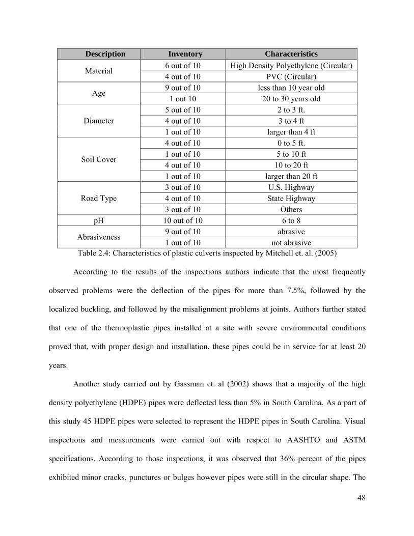
48
Description Inventory Characteristics 6 out of 10 High Density Polyethylene (Circular)
Material 4 out of 10 PVC (Circular) 9 out of 10 less than 10 year old
Age 1 out 10 20 to 30 years old
5 out of 10 2 to 3 ft. 4 out of 10 3 to 4 ft Diameter 1 out of 10 larger than 4 ft 4 out of 10 0 to 5 ft. 1 out of 10 5 to 10 ft 4 out of 10 10 to 20 ft
Soil Cover
1 out of 10 larger than 20 ft 3 out of 10 U.S. Highway 4 out of 10 State Highway Road Type 3 out of 10 Others
pH 10 out of 10 6 to 8 9 out of 10 abrasive
Abrasiveness 1 out of 10 not abrasive
Table 2.4: Characteristics of plastic culverts inspected by Mitchell et. al. (2005)
According to the results of the inspections authors indicate that the most frequently
observed problems were the deflection of the pipes for more than 7.5%, followed by the
localized buckling, and followed by the misalignment problems at joints. Authors further stated
that one of the thermoplastic pipes installed at a site with severe environmental conditions
proved that, with proper design and installation, these pipes could be in service for at least 20
years.
Another study carried out by Gassman et. al (2002) shows that a majority of the high
density polyethylene (HDPE) pipes were deflected less than 5% in South Carolina. As a part of
this study 45 HDPE pipes were selected to represent the HDPE pipes in South Carolina. Visual
inspections and measurements were carried out with respect to AASHTO and ASTM
specifications. According to those inspections, it was observed that 36% percent of the pipes
exhibited minor cracks, punctures or bulges however pipes were still in the circular shape. The
49
reason of these deflections and cracks were explained as improper installation techniques such as
poor bedding of soils and inadequate backfilling.
Sargand et al. (2002) studied the long term behavior of profile-wall High Density
Polyethylene Pipes under deep soil cover. Two pipes with diameters of 1050 mm located under
20 ft and 40 ft cover were monitored in this study. According to the results of the paper, both
pipes were found to have a satisfactory performance and the sandy soil with a 96% relative
compaction was determined as good as the crushed limestone with the same compaction level.
A similar study is performed by Adams et. al. (1989) in which 24 in. diameter corrugated
Polyethylene pipe was placed under 95 ft of fill. According to the results of this study the pipe
was observed to remain in its circular shape and the vertical diameter decrease was observed
around 4 percent whereas the horizontal diameter increase was observed around 0.4 percent. The
earth pressure was also measured at the crown section of the pipe and it was determined to be
only 20 percent of the vertical embankment pressure. This study shows the significance of soil-
pipe interaction.
To sum up, plastic pipes can be manufactured with the desired durability to withstand the
effects of corrosion and abrasion however installation and backfilling procedures have to be
handled with care. Similar to the other flexible culvert types, plastic culverts also depend on the
soil–structure interaction in terms of structural stability. Improper design and/or installation
techniques may lead to deflections and misalignments in plastic culverts.
2.3.4 Aluminum Culverts:
Aluminum has been used as a construction material for drainage structures for
approximately 50 years in the United States. Having a better corrosion resistance compared to

50
metal culverts made aluminum culverts the choice of designers in many sites. Allemeier gives
the advantages and disadvantages of aluminum as follows (Ring, 1984):
Advantages of Aluminum:
• They are ideal for shipping due to their very light weight.
• Their sizes and shapes vary in a large range.
• The thickness of the sheets and also the corrugations can be selected from a wide range in
order to obtain the required strength.
• Easy and fast assembling and installation procedures.
• They have better resistance against corrosion than steel pipes in salty water.
Disadvantages of aluminum are listed as follows:
• Corrugation roughness decreases the rate of flow except for the smooth-lines pipes.
• In case of significant amount of presence of sand and/or rock in a high velocity stream,
abrasion may cause loss of material.
• They are generally more expensive than steel pipes.
• Installation procedures have to be handled more carefully compared to steel pipes due to
higher flexibility.
• They are more sensitive to the live and dead loads compared to the steel pipes due to
higher flexibility.
Summerson (1984), explains the high corrosion resistance of aluminum pipes with the
oxide films produced by the chemical reactions on the surface of the pipe. The author states that
this very thin layer of oxide film is extremely stable and therefore does not show any reaction
over a wide range of conditions and even in a case of mechanical damage such as abrasion the
film refreshes itself instantly. The author further states that corrosion may be a problem on some

51
defective areas on the pipe where the oxide film has some micro defects due to the metallurgical
properties however; this corrosion takes place locally as a form of pitting therefore it does not
affect the overall durability of the pipe drastically. Summerson does field inspections and
laboratory tests in California in order to prove the theoretical corrosion resistance of aluminum
culverts. According to the results of the inspection, when aluminum pipes are used at the sites
where pH values are within the specifications (between 4 and 9) and the minimum resistivities
are 500 ohm-cm aluminum pipes show excellent performance.
Bellair and Ewing (1984) investigated and compared the metal-loss rates observed in
uncoated steel and aluminum culverts in New York. The field survey included 190 galvanized
steel culverts and 35 aluminum culverts. According to their findings, aluminum culverts showed
significantly better performance than uncoated steel culverts throughout the state and with the
application of statistical analysis to the field data they have reached to the conclusion that 35 mil
thickness of material was satisfactory for a 70-year design life, which was already within the
minimum thickness requirement.
Hurd et. al. (1991), investigated the structural performance of an aluminum box culvert
during the installation and live load application on the structure. The culvert selected for
investigation was a corrugated aluminum box culvert with a span of 14 ft 10 in, a rise of 4 ft 10
in. and a length of 42 ft. Deflections and strains along the culvert were recorded and results were
analyzed with computer programs and a finite element analysis was made. As a result of the
analysis it was concluded that the structural performance of the aluminum culvert was
satisfactory and finite element analysis was proved to be beneficial in analyzing and designing
these structures. Some criticism about the computer program CANDE was made after comparing
the actual measurements and computer outputs.

52
To sum up, aluminum culverts and aluminum coated culverts can be considered to have
better corrosion resistance compared to steel culverts if they are used on the sites within the
design limits; however, installation and backfilling procedures should be handled with a greater
care due to the higher flexibility.
2.4 Culvert Asset Management
Culvert asset management provides the ability to show how, when, and why culvert
resources were/are committed. Transportation officials are highly accountable for all
transportation assets. Even though, periodic inspections and preventive repairs may appear to
cause an added economic burden, the transportation agencies, will obtain tremendous cost
savings by lowering the emergency repair costs due to reduced number of failures. The traveling
public will benefit from culvert asset management because user delays are minimized. Asset
management practices also improve efficiency and increase the value of services to
transportation users.
Some of the benefits to DOTs from asset management practices are (Perrin, 2004):
• Accountability to the public
• Increased budget demands
• Rational approach to resource allocation
• Defense against politicizing the program
The American Association of State Highway and Transportation Officials (AASHTO)
and Federal Highway Association (FHWA) recommend that asset management is a better way to
do business. They provide national leadership and guidance to states for implementing and
developing asset management in all states (Perrin, 2004). The culvert management system allows

53
the transportation agency to have an inventory of culverts, and to develop a short and long-term
plan for maintenance and renewal (FHWA, 2001).
54
3. National Survey
One of the objectives of this project is to conduct a national survey among the
departments of transportation (DOTs) in the United States in order to develop a database of
trenchless technology methods that are being used to repair and renew culverts. The outcome of
this survey would provide valuable detailed information regarding the use of trenchless
technologies such as frequency, advantages and disadvantages of each method employed as well
as the DOTs’ insights of these methods.
The survey was prepared by the researchers after performing the literature review on the
trenchless repair and renewal methods. It was structured as 3 parts. First part consisted questions
regarding the contact information of the respondent. Second part focused on culvert asset
management issues and the last part focused on culvert repair and renewal methods and usage of
trenchless technologies. A copy of the survey form can be seen in Appendix 1.
The survey was conducted electronically through the mailing list of ODOT and sent to
the DOTs on three occasions. The first round of survey was conducted in March 2008 and it was
re-conducted due to low number of responses in April and May 2008 for the second and third
times respectively. Ohio, Texas, Minnesota, Missouri, West Virginia, Maryland, New York, and
California State DOTs responded to the questionnaire. One of respondents indicated that they are
not aware of any trenchless technologies used for the renewal of culverts in their state and
preferred not to fill out the survey form. Therefore the outcomes of this questionnaire are going
to be presented in the following sections according to the responses of seven state DOT officials.
Due to the low number of responses statistical analysis of the results is not performed.
Investigators believe that the low number of responses were due to the fact that majority
of the state DOTs are not yet familiar with several trenchless technology methods and state

55
DOTs are relying on the manufacturers’ and contractors’ experience and knowledge. Although
information gathered from the survey was limited in detail, it provided an insight about the
application of trenchless technologies to culverts by state departments of transportation.
3.1 Results of the Survey
The survey consisted of 22 questions in total. First part of the questions, (questions from
1 to 9) address culvert asset management strategies of DOTs, second part of the questions
(questions from 10 to 22) address culvert repair and renewal procedures and usage of trenchless
technologies. The results of the survey are going to be presented under these two groups.
3.1.1 Culvert Asset Management
Question 1: What is the definition of a culvert in your agency?
The responses to this question are given in Table 3.1. The primary purpose of a culvert,
that is carrying live and dead loads due to roadway and forming a passageway for water, is
common in the answers. The maximum size of a culvert which differentiates it from a bridge
varies from state to state. 4 states indicated that if a culvert is larger than 20 ft then it is
categorized as a bridge whereas 1 of respondents indicated that culverts larger than 10 ft are
classified as bridges in their state.
Question 2: What is the approximate breakdown of culverts with respect to their material
type in your state?
The responses to this question are given in Table 3.2. For the states who responded to the
questionnaire, concrete and metal culverts constitute approximately 95% of overall culverts.
Concrete is the dominant material of choice for culverts among respondents.
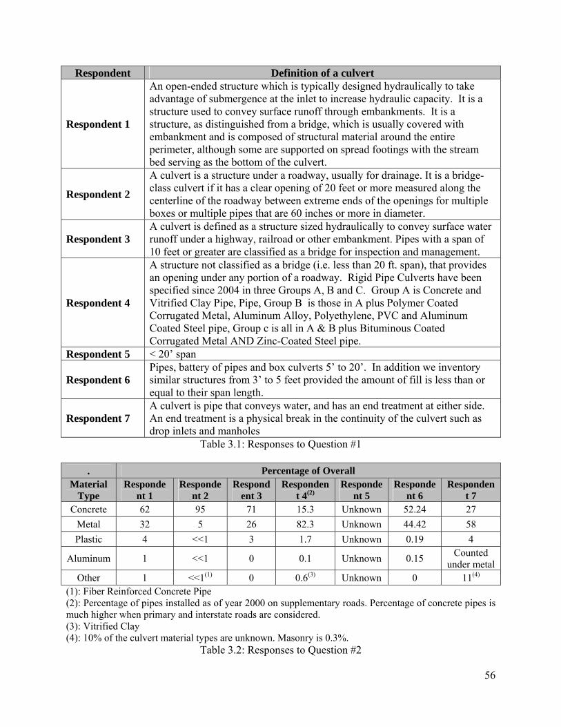
56
Respondent Definition of a culvert
Respondent 1
An open-ended structure which is typically designed hydraulically to take advantage of submergence at the inlet to increase hydraulic capacity. It is a structure used to convey surface runoff through embankments. It is a structure, as distinguished from a bridge, which is usually covered with embankment and is composed of structural material around the entire perimeter, although some are supported on spread footings with the stream bed serving as the bottom of the culvert.
Respondent 2
A culvert is a structure under a roadway, usually for drainage. It is a bridge-class culvert if it has a clear opening of 20 feet or more measured along the centerline of the roadway between extreme ends of the openings for multiple boxes or multiple pipes that are 60 inches or more in diameter.
Respondent 3 A culvert is defined as a structure sized hydraulically to convey surface water runoff under a highway, railroad or other embankment. Pipes with a span of 10 feet or greater are classified as a bridge for inspection and management.
Respondent 4
A structure not classified as a bridge (i.e. less than 20 ft. span), that provides an opening under any portion of a roadway. Rigid Pipe Culverts have been specified since 2004 in three Groups A, B and C. Group A is Concrete and Vitrified Clay Pipe, Pipe, Group B is those in A plus Polymer Coated Corrugated Metal, Aluminum Alloy, Polyethylene, PVC and Aluminum Coated Steel pipe, Group c is all in A & B plus Bituminous Coated Corrugated Metal AND Zinc-Coated Steel pipe.
Respondent 5 < 20’ span
Respondent 6 Pipes, battery of pipes and box culverts 5’ to 20’. In addition we inventory similar structures from 3’ to 5 feet provided the amount of fill is less than or equal to their span length.
Respondent 7 A culvert is pipe that conveys water, and has an end treatment at either side. An end treatment is a physical break in the continuity of the culvert such as drop inlets and manholes
Table 3.1: Responses to Question #1
. Percentage of Overall Material
Type Responde
nt 1 Responde
nt 2 Respond
ent 3 Responden
t 4(2) Responde
nt 5 Responde
nt 6 Responden
t 7
Concrete 62 95 71 15.3 Unknown 52.24 27 Metal 32 5 26 82.3 Unknown 44.42 58 Plastic 4 <<1 3 1.7 Unknown 0.19 4
Aluminum 1 <<1 0 0.1 Unknown 0.15 Counted under metal
Other 1 <<1(1) 0 0.6(3) Unknown 0 11(4) (1): Fiber Reinforced Concrete Pipe (2): Percentage of pipes installed as of year 2000 on supplementary roads. Percentage of concrete pipes is much higher when primary and interstate roads are considered. (3): Vitrified Clay (4): 10% of the culvert material types are unknown. Masonry is 0.3%.
Table 3.2: Responses to Question #2
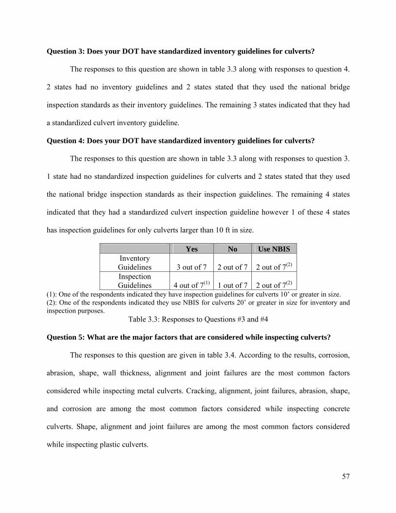
57
Question 3: Does your DOT have standardized inventory guidelines for culverts?
The responses to this question are shown in table 3.3 along with responses to question 4.
2 states had no inventory guidelines and 2 states stated that they used the national bridge
inspection standards as their inventory guidelines. The remaining 3 states indicated that they had
a standardized culvert inventory guideline.
Question 4: Does your DOT have standardized inventory guidelines for culverts?
The responses to this question are shown in table 3.3 along with responses to question 3.
1 state had no standardized inspection guidelines for culverts and 2 states stated that they used
the national bridge inspection standards as their inspection guidelines. The remaining 4 states
indicated that they had a standardized culvert inspection guideline however 1 of these 4 states
has inspection guidelines for only culverts larger than 10 ft in size.
Yes No Use NBIS Inventory Guidelines 3 out of 7 2 out of 7 2 out of 7(2)
Inspection Guidelines 4 out of 7(1) 1 out of 7 2 out of 7(2)
(1): One of the respondents indicated they have inspection guidelines for culverts 10’ or greater in size. (2): One of the respondents indicated they use NBIS for culverts 20’ or greater in size for inventory and inspection purposes.
Table 3.3: Responses to Questions #3 and #4
Question 5: What are the major factors that are considered while inspecting culverts?
The responses to this question are given in table 3.4. According to the results, corrosion,
abrasion, shape, wall thickness, alignment and joint failures are the most common factors
considered while inspecting metal culverts. Cracking, alignment, joint failures, abrasion, shape,
and corrosion are among the most common factors considered while inspecting concrete
culverts. Shape, alignment and joint failures are among the most common factors considered
while inspecting plastic culverts.
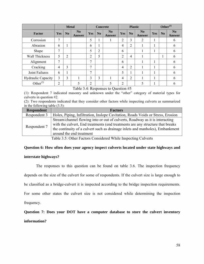
58
Metal Concrete Plastic Other(1)
Factor Yes No No Answer Yes No No
Answer Yes No No Answer Yes No No
Answer Corrosion 7 5 1 1 2 3 2 1 6 Abrasion 6 1 6 1 4 2 1 1 6
Shape 7 5 2 6 1 1 6 Wall Thickness 5 2 2 5 2 4 1 1 6
Alignment 7 7 6 1 1 6 Cracking 4 3 7 4 2 1 1 6
Joint Failures 6 1 7 5 1 1 1 6 Hydraulic Capacity 3 3 1 3 3 1 4 2 1 1 6
Other(2) 2 5 2 5 2 5 1 6 Table 3.4: Responses to Question #5
(1): Respondent 7 indicated masonry and unknown under the “other” category of material types for culverts in question #2. (2): Two respondents indicated that they consider other factors while inspecting culverts as summarized in the following table (3.5):
Respondent Factors Respondent 3 Holes, Piping, Infiltration, Inslope Cavitation, Roads Voids or Stress, Erosion
Respondent 7
Stream/channel flowing into or out of culverts, Roadway as it is interacting with the culvert, End treatments (end treatments are any structure that breaks the continuity of a culvert such as drainage inlets and manholes), Embankment around the end treatment
Table 3.5: Other Factors Considered While Inspecting Culverts
Question 6: How often does your agency inspect culverts located under state highways and
interstate highways?
The responses to this question can be found on table 3.6. The inspection frequency
depends on the size of the culvert for some of respondents. If the culvert size is large enough to
be classified as a bridge-culvert it is inspected according to the bridge inspection requirements.
For some other states the culvert size is not considered while determining the inspection
frequency.
Question 7: Does your DOT have a computer database to store the culvert inventory
information?

59
The responses to this question are given along with responses to question 8 and 9 in table
3.7. According to the results it can be seen that some of states do not have a computerized
database to store the culvert inventory information. One of the respondents indicated they have
the database for only culverts that are larger than 20 ft.
Respondent Inspection Frequency Respondent 1 Every 5 years Respondent 2 24 - 48 months
Respondent 3
No required inspection frequency for pipes smaller than 10 ft. Culverts 10 feet and greater are designated as bridges and follow bridge management inspection frequency 1 to 2 years.
Respondent 4 Box culverts are inspected every 5 years. Pipe culverts are inspected only as needed.
Respondent 5 5 years for culverts 10 feet or greater Respondent 6 4 years
Respondent 7 Currently still on the first cycle of our complete condition survey, with revisits done on an as needed basis
Table 3.6: Responses to Question #6
Question 8: Is there a model or formula that your agency uses in order to determine the
remaining service life of culverts depending on the inspection results?
The responses to this question are given along with responses to question 7 and 9 in table
3.7. Only one respondent indicated that they use have a formula to calculate the remaining
service life of a culvert depending on the inspection result. The respondent provided a copy of
the project report in which a comprehensive examination of culverts was performed and
researchers reached service life equations for metal and concrete culverts in 1982.
Question 9: Does your DOT have a decision support system which integrates the culvert
inventory, condition assessment and repair/renewal method selection?
The responses to this question are given along with responses to question 7 and 8 in table
3.7. Three (3) respondents indicated that they have a decision support system which integrates
inventory, inspection and repair/renewal method selection. One of these three respondents added
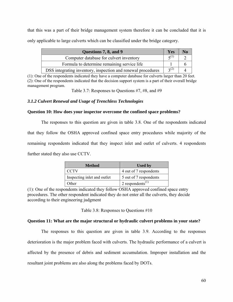
60
that this was a part of their bridge management system therefore it can be concluded that it is
only applicable to large culverts which can be classified under the bridge category.
Questions 7, 8, and 9 Yes No Computer database for culvert inventory 5(1) 2
Formula to determine remaining service life 1 6 DSS integrating inventory, inspection and renewal procedures 3(2) 4
(1): One of the respondents indicated they have a computer database for culverts larger than 20 feet. (2): One of the respondents indicated that the decision support system is a part of their overall bridge management program.
Table 3.7: Responses to Questions #7, #8, and #9
3.1.2 Culvert Renewal and Usage of Trenchless Technologies
Question 10: How does your inspector overcome the confined space problems?
The responses to this question are given in table 3.8. One of the respondents indicated
that they follow the OSHA approved confined space entry procedures while majority of the
remaining respondents indicated that they inspect inlet and outlet of culverts. 4 respondents
further stated they also use CCTV.
Method Used by CCTV 4 out of 7 respondents Inspecting inlet and outlet 5 out of 7 respondents Other 2 respondents(1)
(1): One of the respondents indicated they follow OSHA approved confined space entry procedures. The other respondent indicated they do not enter all the culverts, they decide according to their engineering judgment
Table 3.8: Responses to Questions #10
Question 11: What are the major structural or hydraulic culvert problems in your state?
The responses to this question are given in table 3.9. According to the responses
deterioration is the major problem faced with culverts. The hydraulic performance of a culvert is
affected by the presence of debris and sediment accumulation. Improper installation and the
resultant joint problems are also along the problems faced by DOTs.

61
Respondent Major structural or hydraulic culvert problems
Respondent 1 Structural: Proper Installation Hydraulic: No major problems
Respondent 2 Structural deterioration, debris and sediment accumulation Respondent 3 Joint separation in concrete pipes and holes in metal pipes
Respondent 4 Use of materials other than reinforced concrete pipe under roadways with over 7500 ADT in order to reduce costs Rusting out of metal culverts within 5 years of installation in mining areas.
Respondent 5 Abrasive soils and acidic water Respondent 6 Rusted inverts Respondent 7 Debris and corroded inverts, End of service life
Table 3.9: Responses to Questions #11
Question 12: What are the most common maintenance / repair methods in your state?
The responses to this question are given in table 3.10. It can be seen that paving the
inverts of culverts is among the most common repair methods used by DOTs. One of the
respondents also indicated that they use internal sleeves to repair joints. Repairing the concrete
inslope sections of culverts is also mentioned by one of the respondents.
Respondent Most common maintenance / repair methods Respondent 1 Paved Invert, Joint Repair with expandable internal sleeve Respondent 2 Reconstruction of short pipe lengths is very uncommon. Respondent 3 Resetting concrete sections at inslope
Respondent 4 Replacing ends of pipe as problems reach the shoulder line. Sometimes when rusted out, paving inverts with concrete or HMA
Respondent 5 Reconstruction of partial length Respondent 6 Grout line the inverts Respondent 7 Culvert lining
Table 3.10: Responses to Questions #12
Question 13: What are the most common rehabilitation or replacement methods in your
state?
The responses to this question are given in table 3.11. According to the responses
rehabilitating existing culverts with liners is a commonly employed method. It can be seen that
open cut replacement is the main method of replacing culverts among the respondents.
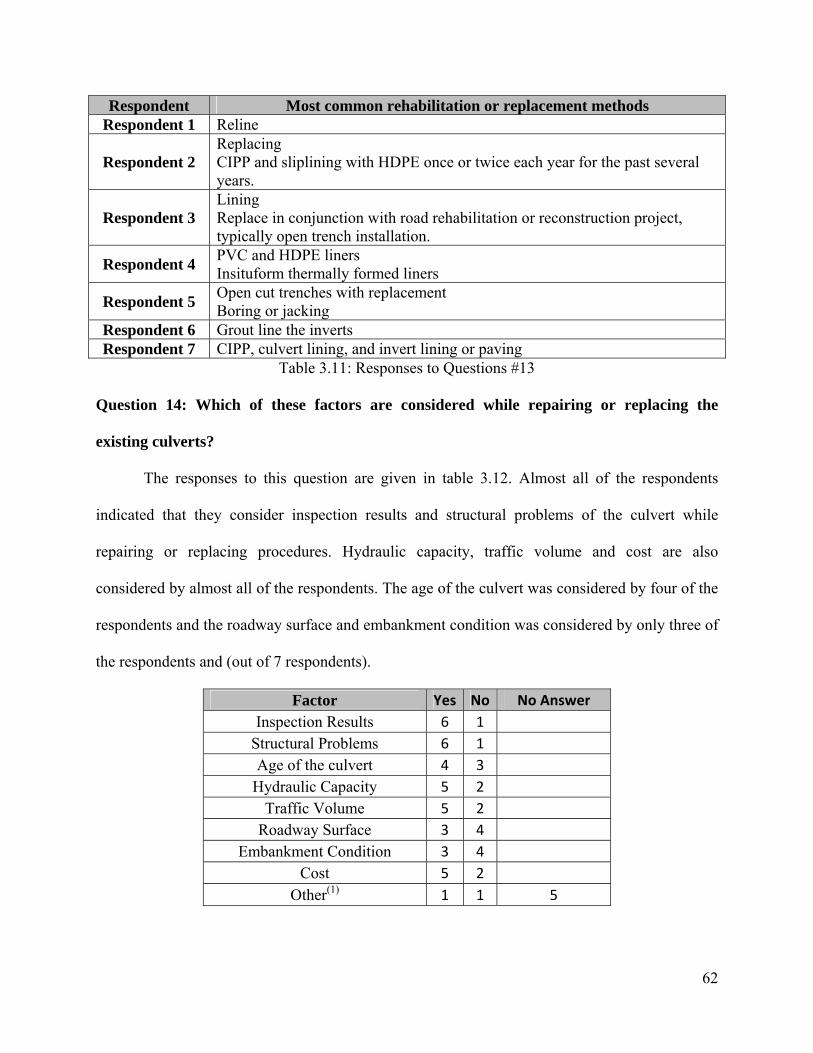
62
Respondent Most common rehabilitation or replacement methods Respondent 1 Reline
Respondent 2 Replacing CIPP and sliplining with HDPE once or twice each year for the past several years.
Respondent 3 Lining Replace in conjunction with road rehabilitation or reconstruction project, typically open trench installation.
Respondent 4 PVC and HDPE liners Insituform thermally formed liners
Respondent 5 Open cut trenches with replacement Boring or jacking
Respondent 6 Grout line the inverts Respondent 7 CIPP, culvert lining, and invert lining or paving
Table 3.11: Responses to Questions #13
Question 14: Which of these factors are considered while repairing or replacing the
existing culverts?
The responses to this question are given in table 3.12. Almost all of the respondents
indicated that they consider inspection results and structural problems of the culvert while
repairing or replacing procedures. Hydraulic capacity, traffic volume and cost are also
considered by almost all of the respondents. The age of the culvert was considered by four of the
respondents and the roadway surface and embankment condition was considered by only three of
the respondents and (out of 7 respondents).
Factor Yes No No Answer Inspection Results 6 1
Structural Problems 6 1 Age of the culvert 4 3
Hydraulic Capacity 5 2 Traffic Volume 5 2
Roadway Surface 3 4 Embankment Condition 3 4
Cost 5 2 Other(1) 1 1 5

63
(1): One of the respondents indicated that they also consider the following factors: access to pipe such as right of way to do repair or replace technique, scheduled road project, cover, size and, shape (round, arch, box) of pipe, rocks in soil (can be problem with jacking)
Table 3.12: Responses to Questions #14
Question 15: What are the trenchless renewal methods employed in your state and what is
the frequency of use for each method on the average per year?
The responses to this question are given in table 3.13. According to the results sliplining,
grouting, and cured-in-place pipe methods are the trenchless methods employed by the highest
number of respondents. Among these methods, sliplining seems to have the highest frequency of
use and cured-in-place seems to have the lowest frequency of use.
Method Yes No No Answer Frequency
Cured-in-Place Pipe 4 2 1 No answer(1), 2-4(2), 10%(3), Frequent(7)
Sliplining 6 1
Used most often(1), 20(2), 90%(3), 1-2(4),
No answer(5), Frequent(7)
Pipe Bursting 1 4 2 Tested Once(3)
Pipe Reaming 5 2 N/A
Pipe Eating 5 2 N/A Pipe Ejection/Extraction 5 2 N/A
Close-Fit Pipe 5 2 N/A Panel Lining 1 4 2 1 or 2(5)
Robotic Repair 5 2 N/A
Grouting 5 1 1 Occasional(3), 20(4), 10(5), no answer(6),
Rarely(7)
Internal Seal 2 3 2 Occasional(3,7)
Point CIPP 1 4 2 Occasional(3)
Cement Mortar Lining 2 3 2 Occasional(3), Rarely(7)
Epoxy Coating 1 4 2 Once or twice(7)
Thermoformed Pipe 1 4 2 1 or 2 only(4)
Other 1(*) 6 A few times(7)
(*): One of the respondents indicated they used Spiral Wound PVC Lining (1): Frequency reported by respondent 1.

64
(2): Frequency reported by respondent 2. (3): Frequency reported by respondent 3. (4): Frequency reported by respondent 4. (5): Frequency reported by respondent 5. (6): Frequency reported by respondent 6. (7): Frequency reported by respondent 7.
Table 3.13: Responses to Questions #15
Question 16: For each of the trenchless methods employed before what are the critical pre-
construction, construction and post-construction issues?
The responses to this question are given in table 3.14. The critical issues while employing
the three common trenchless repair and renewal procedures (sliplining, cured-in-place pipe and
grouting) are as follows: According to the results the pipe to be sliplined needs to be free of
debris, excessive misalignment and deformations prior to the start of renewal procedures. The
opening in the existing pipe should not restrict the insertion of the lining pipe. During the
sliplining process it is important to pay attention to the grouting procedure to avoid floating
and/or bulging of the liner pipe. Providing a staging area is also important during sliplining.
During grouting procedure the pipe size should be checked against whether it allows access or
not. During the cured-in-place pipe applications the existing pipe should be cleaned and the
surface of the pipe should be prepared to prevent any irregularities in the finished CIPP and to
provide a tight fit of the liner with the pipe. The cured-in-place pipe procedure also requires
adequate curing procedures.
Method Respondent Pre-Construction Construction Post-
Construction
Respondent 1 Debris clean out, Access No Answer
Respondent 2 Used infrequently, Rely on Manufacturer's recommendations
Cured-in-Place Pipe
Respondent 3
Cost/ Benefit, Traffic, Use with Asbestos Bonded
Grout road voids, let contract with multiple cipp
liners
No answer

65
Method Respondent Pre-Construction Construction Post-
Construction
Respondent 7
Pipe deformation and cross section Adequacy of cure
No Answer
Respondent 1 Debris Clean Out, Access Maximum opening, grouting No
Answer Respondent
2 Used infrequently, Rely on Manufacturer's recommendations
Respondent 3
No deformation or misalignment in existing pipe, hydraulic capacity
Staging area required, grouting voids can cause
bulged pipe
No answer
Respondent 4 No answer Room to insert liner No
answer Respondent
5 Unknown conditions Grouting No answer
Sliplining
Respondent 7
Cross section, available space for insertion Annulus grouting pressure
No Answer
Pipe Bursting
Respondent 3 Rocks No Answer
Panel Lining
Respondent 6 No answer
Respondent 3 Access - pipe size No Answer
Respondent 4 No answer
Respondent 5 No answer
Respondent 6 No answer
Grouting
Respondent 7 No answer
Respondent 3 Access - pipe size No answer Internal
Seal Respondent 7
Pipe stability, working space
Achieving water tight seal and testing
No Answer
Point CIPP
Respondent 3 No answer
Respondent 3
Access - pipe size, pipe strength No Answer Cement
Mortar Lining Respondent
7 Use of fibers for
reinforcing vs WWM No Answer
Epoxy Coating
Respondent 7 Toxicity of material Bond strength
No Answer
Thermoformed Pipe
Respondent 4 Clean Pipe Inspection
Inspection
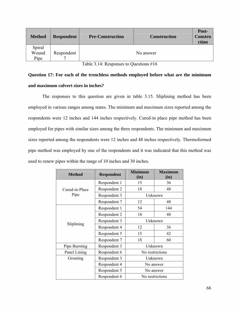
66
Method Respondent Pre-Construction Construction Post-
Construction
Spiral Wound
Pipe Respondent
7 No answer
Table 3.14: Responses to Questions #16
Question 17: For each of the trenchless methods employed before what are the minimum
and maximum culvert sizes in inches?
The responses to this question are given in table 3.15. Sliplining method has been
employed in various ranges among states. The minimum and maximum sizes reported among the
respondents were 12 inches and 144 inches respectively. Cured-in place pipe method has been
employed for pipes with similar sizes among the three respondents. The minimum and maximum
sizes reported among the respondents were 12 inches and 48 inches respectively. Thermoformed
pipe method was employed by one of the respondents and it was indicated that this method was
used to renew pipes within the range of 10 inches and 30 inches.
Method Respondent Minimum (in)
Maximum (in)
Respondent 1 15 36 Respondent 2 18 48 Respondent 3 Unknown
Cured-in-Place Pipe
Respondent 7 12 48 Respondent 1 54 144 Respondent 2 18 48 Respondent 3 Unknown Respondent 4 12 36 Respondent 5 15 42
Sliplining
Respondent 7 18 60 Pipe Bursting Respondent 3 Unknown Panel Lining Respondent 6 No restrictions
Respondent 3 Unknown Respondent 4 No answer Respondent 5 No answer
Grouting
Respondent 6 No restrictions
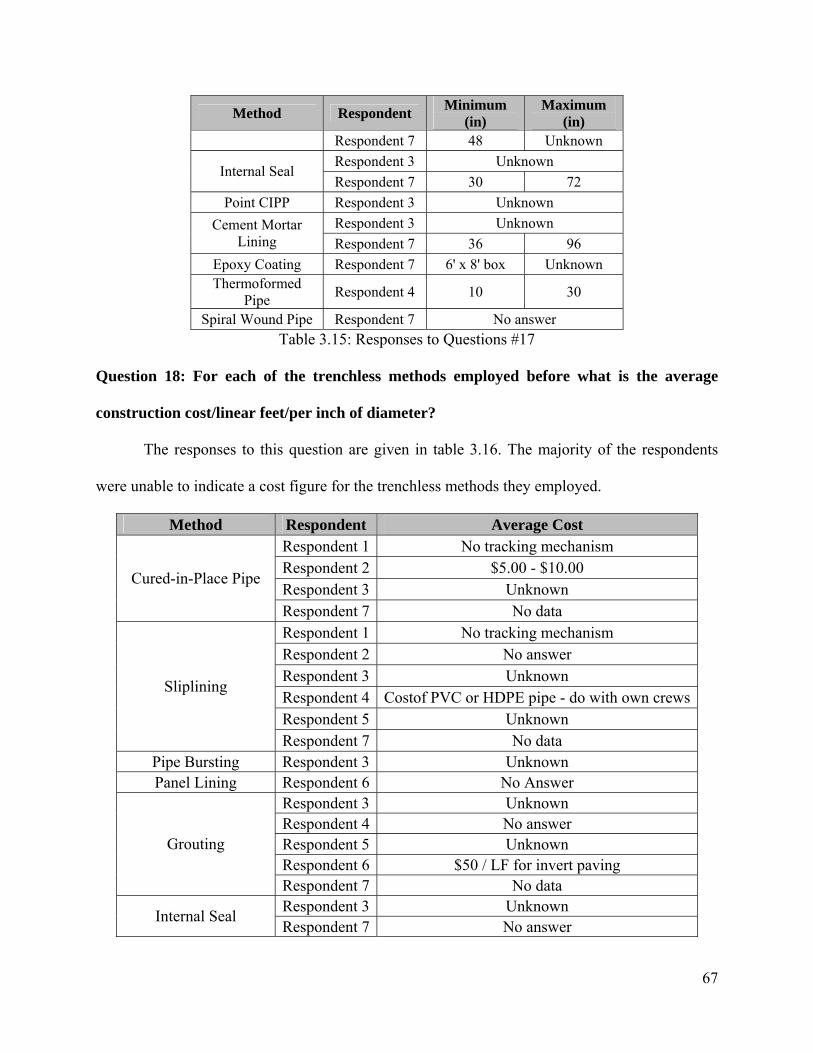
67
Method Respondent Minimum (in)
Maximum (in)
Respondent 7 48 Unknown Respondent 3 Unknown
Internal Seal Respondent 7 30 72
Point CIPP Respondent 3 Unknown Respondent 3 Unknown Cement Mortar
Lining Respondent 7 36 96 Epoxy Coating Respondent 7 6' x 8' box Unknown Thermoformed
Pipe Respondent 4 10 30
Spiral Wound Pipe Respondent 7 No answer Table 3.15: Responses to Questions #17
Question 18: For each of the trenchless methods employed before what is the average
construction cost/linear feet/per inch of diameter?
The responses to this question are given in table 3.16. The majority of the respondents
were unable to indicate a cost figure for the trenchless methods they employed.
Method Respondent Average Cost Respondent 1 No tracking mechanism Respondent 2 $5.00 - $10.00 Respondent 3 Unknown
Cured-in-Place Pipe
Respondent 7 No data Respondent 1 No tracking mechanism Respondent 2 No answer Respondent 3 Unknown Respondent 4 Costof PVC or HDPE pipe - do with own crewsRespondent 5 Unknown
Sliplining
Respondent 7 No data Pipe Bursting Respondent 3 Unknown Panel Lining Respondent 6 No Answer
Respondent 3 Unknown Respondent 4 No answer Respondent 5 Unknown Respondent 6 $50 / LF for invert paving
Grouting
Respondent 7 No data Respondent 3 Unknown Internal Seal Respondent 7 No answer
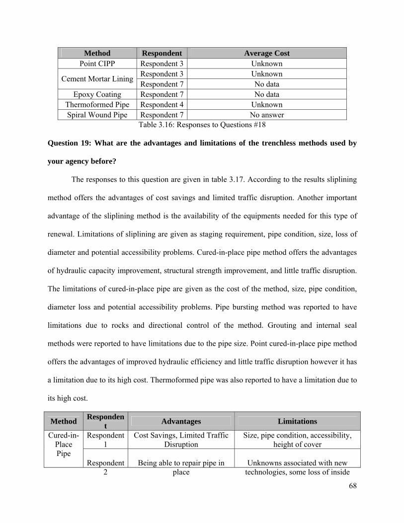
68
Method Respondent Average Cost Point CIPP Respondent 3 Unknown
Respondent 3 Unknown Cement Mortar Lining Respondent 7 No data
Epoxy Coating Respondent 7 No data Thermoformed Pipe Respondent 4 Unknown Spiral Wound Pipe Respondent 7 No answer
Table 3.16: Responses to Questions #18
Question 19: What are the advantages and limitations of the trenchless methods used by
your agency before?
The responses to this question are given in table 3.17. According to the results sliplining
method offers the advantages of cost savings and limited traffic disruption. Another important
advantage of the sliplining method is the availability of the equipments needed for this type of
renewal. Limitations of sliplining are given as staging requirement, pipe condition, size, loss of
diameter and potential accessibility problems. Cured-in-place pipe method offers the advantages
of hydraulic capacity improvement, structural strength improvement, and little traffic disruption.
The limitations of cured-in-place pipe are given as the cost of the method, size, pipe condition,
diameter loss and potential accessibility problems. Pipe bursting method was reported to have
limitations due to rocks and directional control of the method. Grouting and internal seal
methods were reported to have limitations due to the pipe size. Point cured-in-place pipe method
offers the advantages of improved hydraulic efficiency and little traffic disruption however it has
a limitation due to its high cost. Thermoformed pipe was also reported to have a limitation due to
its high cost.
Method Respondent Advantages Limitations
Respondent 1
Cost Savings, Limited Traffic Disruption
Size, pipe condition, accessibility, height of cover
Cured-in-Place Pipe
Respondent 2
Being able to repair pipe in place
Unknowns associated with new technologies, some loss of inside
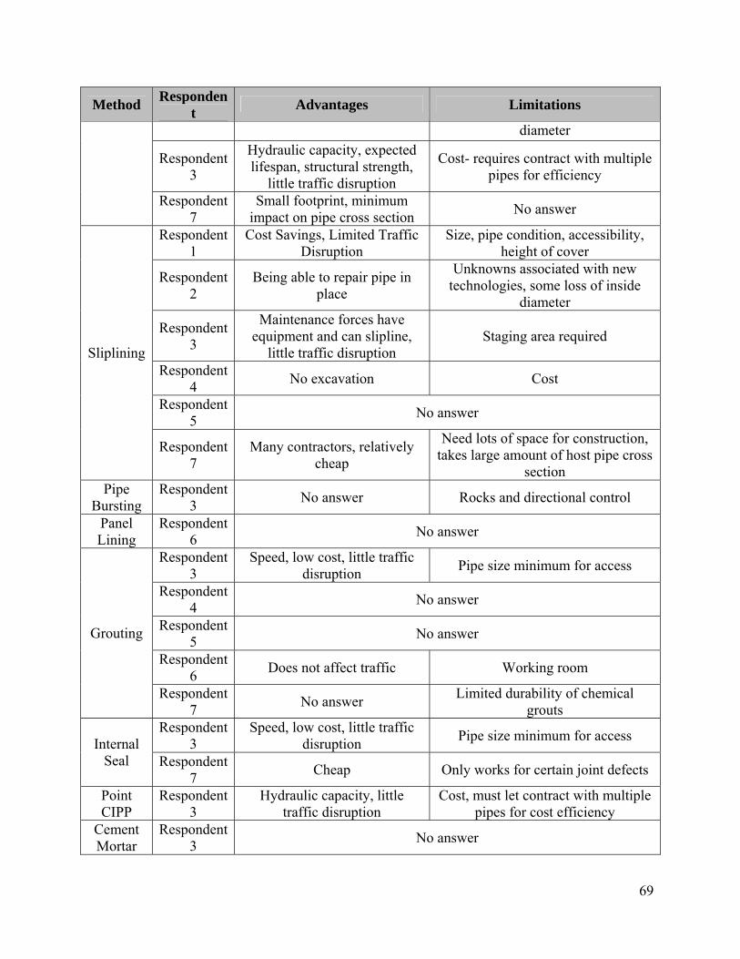
69
Method Respondent Advantages Limitations
diameter
Respondent 3
Hydraulic capacity, expected lifespan, structural strength,
little traffic disruption
Cost- requires contract with multiple pipes for efficiency
Respondent 7
Small footprint, minimum impact on pipe cross section No answer
Respondent 1
Cost Savings, Limited Traffic Disruption
Size, pipe condition, accessibility, height of cover
Respondent 2
Being able to repair pipe in place
Unknowns associated with new technologies, some loss of inside
diameter
Respondent 3
Maintenance forces have equipment and can slipline,
little traffic disruption Staging area required
Respondent 4 No excavation Cost
Respondent 5 No answer
Sliplining
Respondent 7
Many contractors, relatively cheap
Need lots of space for construction, takes large amount of host pipe cross
section Pipe
Bursting Respondent
3 No answer Rocks and directional control
Panel Lining
Respondent 6 No answer
Respondent 3
Speed, low cost, little traffic disruption Pipe size minimum for access
Respondent 4 No answer
Respondent 5 No answer
Respondent 6 Does not affect traffic Working room
Grouting
Respondent 7 No answer Limited durability of chemical
grouts Respondent
3 Speed, low cost, little traffic
disruption Pipe size minimum for access Internal Seal Respondent
7 Cheap Only works for certain joint defects
Point CIPP
Respondent 3
Hydraulic capacity, little traffic disruption
Cost, must let contract with multiple pipes for cost efficiency
Cement Mortar
Respondent 3 No answer
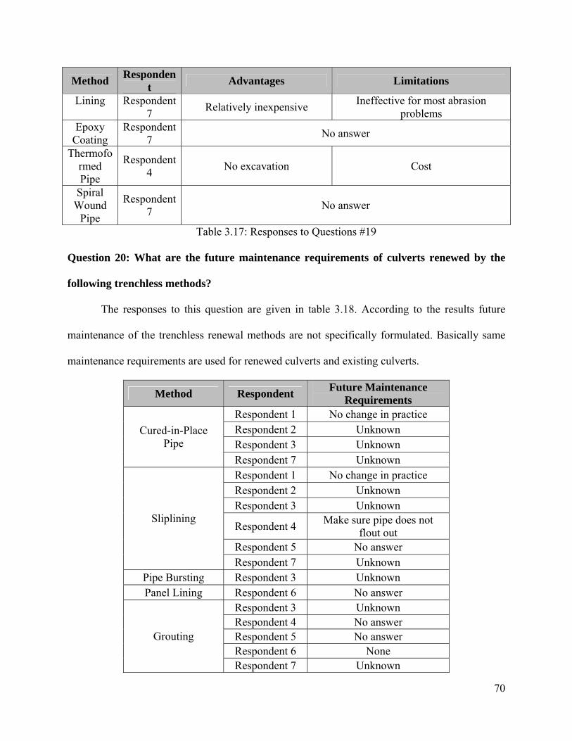
70
Method Respondent Advantages Limitations
Lining Respondent 7 Relatively inexpensive Ineffective for most abrasion
problems Epoxy
Coating Respondent
7 No answer
Thermoformed Pipe
Respondent 4 No excavation Cost
Spiral Wound
Pipe
Respondent 7 No answer
Table 3.17: Responses to Questions #19
Question 20: What are the future maintenance requirements of culverts renewed by the
following trenchless methods?
The responses to this question are given in table 3.18. According to the results future
maintenance of the trenchless renewal methods are not specifically formulated. Basically same
maintenance requirements are used for renewed culverts and existing culverts.
Method Respondent Future Maintenance Requirements
Respondent 1 No change in practice Respondent 2 Unknown Respondent 3 Unknown
Cured-in-Place Pipe
Respondent 7 Unknown Respondent 1 No change in practice Respondent 2 Unknown Respondent 3 Unknown
Respondent 4 Make sure pipe does not flout out
Respondent 5 No answer
Sliplining
Respondent 7 Unknown Pipe Bursting Respondent 3 Unknown Panel Lining Respondent 6 No answer
Respondent 3 Unknown Respondent 4 No answer Respondent 5 No answer Respondent 6 None
Grouting
Respondent 7 Unknown

71
Method Respondent Future Maintenance Requirements
Respondent 3 Unknown Internal Seal Respondent 7 Unknown
Point CIPP Respondent 3 Unknown Respondent 3 Unknown Cement Mortar
Lining Respondent 7 Unknown Epoxy Coating Respondent 7 Unknown Thermoformed
Pipe Respondent 4 None
Spiral Wound Pipe Respondent 7 Unknown Table 3.18: Responses to Questions #20
Question 21: What are the inspection frequencies of culverts renewed by the following
trenchless methods?
The responses to this question are given in table 3.19. According to the results, inspection
frequency of the culverts renewed by trenchless renewal methods is not specifically defined.
Basically same inspection frequency is used for renewed culverts and existing culverts.
Method Respondent Inspection Frequency Respondent 1 5 years Respondent 2 Same as other culverts Respondent 3 Unknown
Cured-in-Place Pipe
Respondent 7 Unknown Respondent 1 5 years Respondent 2 Same as other culverts Respondent 3 Unknown Respondent 4 N/A Respondent 5 No answer
Sliplining
Respondent 7 Unknown Pipe Bursting Respondent 3 Unknown Panel Lining Respondent 6 no answer
Respondent 3 Unknown Respondent 4 N/A Respondent 5 No answer Respondent 6 Maintain a 4 year cycle
Grouting
Respondent 7 Unknown Internal Seal Respondent 3 Unknown

72
Method Respondent Inspection Frequency Respondent 7 Unknown
Point CIPP Respondent 3 Unknown Respondent 3 Unknown Cement Mortar Lining Respondent 7 Unknown
Epoxy Coating Respondent 7 Unknown Thermoformed Pipe Respondent 4 N/A Spiral Wound Pipe Respondent 7 Unknown
Table 3.19: Responses to Questions #21
Question 22: What are the important factors which influence the decision making
procedure on whether to employ an open-cut (traditional) replacement or to use trenchless
renewal methods?
The responses to this question are given in table 3.20. Almost all of the respondents
indicated that traffic volume and detour availability were considered while deciding on whether
to employ an open-cut (traditional) replacement or to use a trenchless renewal method. Location
and depth of cover was considered by 5 respondents (out of 7 respondents). Another important
factor, whether the repair/replacement could be included in a road project or not, was indicated
by one of the respondents. One of respondents indicated that they consider cost and obstructions
while deciding on whether to employ an open-cut replacement or trenchless repair and renewal.
Factor Yes No No Answer Location 5 2
Traffic Volume 6 1 Detour Availability 6 1
Depth of Cover 5 2 Other 2 5
Table 3.20: Responses to Questions #22
73
4. Survey of Technology Providers
In order to further investigate the trenchless technology methods a survey was planned,
and distributed among all the technology providers known. This survey was divided into three
major parts:
Part1. Contact Information: Respondent identifies himself/herself by filling 11 spaces
with the necessary information.
Part 2. Culvert Asset Management: Respondent was asked to answer nineteen (19)
questions. Question types involved “Fill in the blanks, Yes/No and alternative ranking”.
Part 3. Culvert Construction, Repair, Renovation, Replacement (Renewal) and Usage of
Trenchless Technologies: Respondent was asked to select the types of trenchless methods used
and identify some key characteristics and limitations when using those methods
The survey was developed by the research team and uploaded to a website. The surveyed
companies had the option to submit their responses either electronically or by fax. The survey
form can be seen in Appendix 2. This chapter has the intention to show the results of the survey
in a dynamic and comprehensive manner.
4.1 Results and Analysis
Question 1: Does your company work on culverts?
The survey had 23 responses, out of which 13 companies or 57 percent replied to be
capable to work on culverts; this question must be interpreted as work on renewal purposes by
trenchless methods. It should be noticed that these numbers represent the industry average in the
US. Results can be seen on Figure 4.1
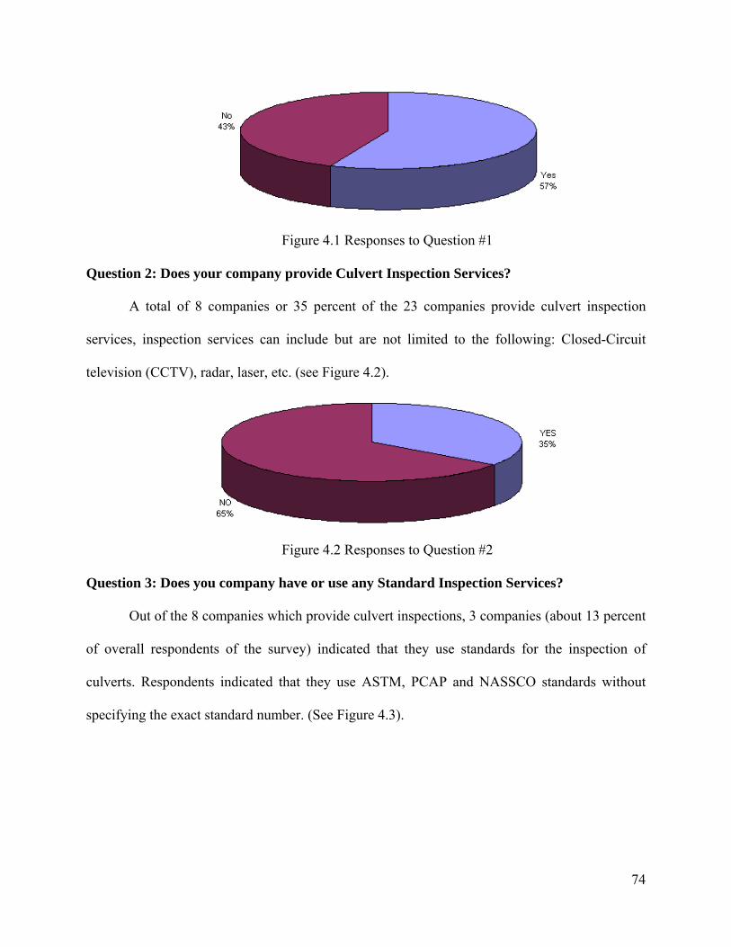
74
Figure 4.1 Responses to Question #1
Question 2: Does your company provide Culvert Inspection Services?
A total of 8 companies or 35 percent of the 23 companies provide culvert inspection
services, inspection services can include but are not limited to the following: Closed-Circuit
television (CCTV), radar, laser, etc. (see Figure 4.2).
Figure 4.2 Responses to Question #2
Question 3: Does you company have or use any Standard Inspection Services?
Out of the 8 companies which provide culvert inspections, 3 companies (about 13 percent
of overall respondents of the survey) indicated that they use standards for the inspection of
culverts. Respondents indicated that they use ASTM, PCAP and NASSCO standards without
specifying the exact standard number. (See Figure 4.3).

75
Figure 4.3 Responses to Question #3
Question 4: Rank the major problems responsible for failure of culverts.
Question 4 solicited the respondents to rank the major problems affecting metal, concrete,
and plastic culverts. According to the experience of the companies, corrosion and abrasion
ranked as the major problems affecting metal culverts; for concrete culverts, joint failure and
cracking ranked as the major ones; and deflection and joint failure ranked as the major problems
suffered by plastic culverts. According to the results, corrosion was not taken into account as a
factor for plastic culverts (see Figure 4.4). It is also noteworthy that wall thickness and hydraulic
capacity remained as factors that have less influence on culvert failure for any type of culvert
material (metal, concrete and plastic). Another type of problem encountered by the surveyed
companies is sedimentation with a rank of 3 out of 7. For illustration purposes number “7” was
given to the factor that affects the most and number “0” to the factor that affects the least (see
Figure 4.4).

76
Figure 4.4 Responses to Question #4
Question 5: Circle the Culvert Materials which your company renews more.
According to the responses from the industry and technology providers metal culverts are
renewed the most, followed by concrete and plastic culverts (see Figure 4.5). This tendency may
be explained due to the higher number of corrugated pipe culverts placed below the roads several
decades ago which nowadays are deteriorating due to completion of their design life
accompanied by the effects of corrosion and abrasion over a long period of time. According to
the survey, other types of renewed culvert materials are wood and clay pipes. For illustration
purposes number “3” was given to the factor that affects the most and number “0” to the factor
that affects the least.
Figure 4.5 Responses to Question #5

77
Question 6: Which Trenchless Renewal Methods does your company carry out?
According to the findings of the survey, sliplining, pipe bursting and CIPP methods
represent almost 45 percent of all the trenchless renewal methods used by companies. The use of
the sliplining method (20 percent) is comparable to the summation of the use of grouting, panel
lining, close-fit pipe and polymer coating. (see Figure 4.6)
Figure 4.6 Responses to Question #6
Question 7: Rank the factors which govern the selection of a particular type of trenchless
renewal method according to their importance.
Cost of repair versus cost of replacement, as well as the condition of the existing culvert
ranked as the two most influential factors when selecting a trenchless method for renewing a
culvert. According to the survey findings aesthetics might not be a crucial issue. Figure 4.7
shows a number of factors that influences the selection of a trenchless renewal project. For
illustration purposes number “13” was given to the factor that affects the most and number “0” to
the factor that affects the least.
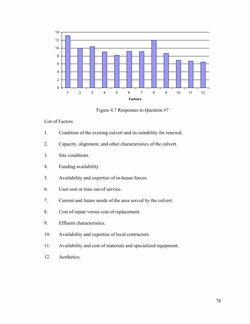
78
Figure 4.7 Responses to Question #7
List of Factors
1. Condition of the existing culvert and its suitability for renewal.
2. Capacity, alignment, and other characteristics of the culvert.
3. Site conditions.
4. Funding availability.
5. Availability and expertise of in-house forces.
6. User cost or time out of service.
7. Current and future needs of the area served by the culvert.
8. Cost of repair versus cost of replacement.
9. Effluent characteristics.
10. Availability and expertise of local contractors.
11. Availability and cost of materials and specialized equipment.
12. Aesthetics.

79
Question 8: Rank the critical pre-construction issues that play a wide role during planning phase on the following Trenchless
Renewal Methods.
According to the responses, the existing condition of a culvert plays a big role during planning phase of using a Trenchless
Renewal Method (See Figure 4.8). It is also important to note that the diameter, shape and material of the culvert become critical
factors when renewing culverts via trenchless methods. On the other hand, the type of flow is the factor that less influences pre-
construction phase among all the trenchless methods listed in Figure 4.8. For illustration purposes number “7” was given to the factor
that affects the most and number “0” to the factor that affects the least (see Figure 4.8).
Figure 4.8 Responses to Question #8
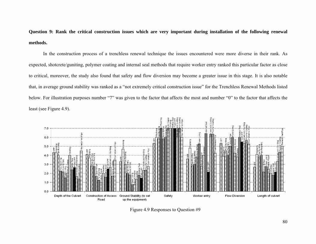
80
Question 9: Rank the critical construction issues which are very important during installation of the following renewal
methods.
In the construction process of a trenchless renewal technique the issues encountered were more diverse in their rank. As
expected, shotcrete/guniting, polymer coating and internal seal methods that require worker entry ranked this particular factor as close
to critical, moreover, the study also found that safety and flow diversion may become a greater issue in this stage. It is also notable
that, in average ground stability was ranked as a “not extremely critical construction issue” for the Trenchless Renewal Methods listed
below. For illustration purposes number “7” was given to the factor that affects the most and number “0” to the factor that affects the
least (see Figure 4.9).
Figure 4.9 Responses to Question #9

81
Question 10: Rank the critical Post-Construction issues that are important following
installation of the following renewal methods.
In the post-construction phase, regular inspections and maintenance factors ranked as
semi-critical factors followed by the length of service. For illustration purposes number “3” was
given to the factor that affects the most and number “0” to the factor that affects the least (see
Figure 4.10).
Figure 4.10 Responses to Question #10
Question 11: What are the important factors in order to decide on whether to do an open-
cut (traditional) replacement or to use trenchless renewal methods? (yes/no)
When asked about if depth of cover, location, and traffic volume were critical factors
while deciding whether to perform an open-cut or trenchless renewal process, all respondents
indicated “yes” to all of them. This situation shows that these factors deserve an important
consideration during the decision making process. However 8% of the companies believe that
detour availability might not represent an important factor when deciding to use trenchless
renewal methods.

82
Figure 4.11 Responses to Question #11
Question 12: Provide the minimum and maximum culverts sizes your company has
employed for the following Trenchless Renewal Methods in inches. Also specify the
Maximum size of the culvert that you think can be installed by the following methods.
The outcome values for this question vary widely; however, the lowest minimum value,
the highest maximum size and the highest accepted size among all the surveyed is given below
(Table 4.1):
Method Minimum Size in Inches
Maximum Size in Inches
Maximum Accepted Size in Inches
Cured-in-Place Pipe (CIPP) 4 in. 120 in. 120 in.
Sliplining 4 in. 96 in. 63 in. Pipe Bursting 3 in. 36 in. 30 in. Pipe Reaming 6 in. 30 in. 48 in. Close-fit pipe 8 in. 24 in. 48 in. Panel Lining 10 in. Unlimited Unlimited
Robotic Repair 6 in. 36 in. 36 in. Grouting 6 in. 120 in. 120 in.
Internal Seal 24 in. 66 in. 144 in. Point CIPP 6 in. 48 in. 120 in.
Shotcrete/Guniting 48 in. 77 in. 144 in. Polymer Coating 48 in. 96 in. 144 in.
Thermoformed Pipe 10 in. 30 in. 30 in. Table 4.1: Responses to Question #12

83
Question 13: What are the limitations for the following Trenchless Renewal Methods?
When the survey turned its focus to the limitations of the trenchless renewal methods,
some important findings appear. All the companies believe that bypassing is needed when using
panel lining, shotcrete/guniting, polymer coating and thermoformed pipe. It is notable as
expected, that the bypassing represents an important problem among all the other methods listed
in Figure 4.12. For the sliplining method it is unavoidable to observe that the seals liner ends are
treated as a great limitation of that trenchless method. The importance of the need for worker
entry for the shotcrete/guniting and for the polymer coating methods should also be noticed.
Question 14: How many years of additional life can be provided to a deteriorated culvert
after it is being renewed by the following methods?
Any renewal method explained in this report has the intention to extend the operational
life of a culvert. Almost 60 years can be added to a culvert when pipe bursting is used to renew
it. Point CIPP, polymer coating, shotcrete and guniting, robotic repair, sliplining, close-fit pipe
and pipe reaming also provide an additional life to a culvert with an average of 50 years,
however it should be noticed that point CIPP offers a local design improvement thus it will not
improve the total length of the culvert. Grouting does not necessarily increase the operational life
of a culvert as shown in Figure 4.13. It is also important to express, these additional operational
life values can only be achieved by the use of good construction means and methods.
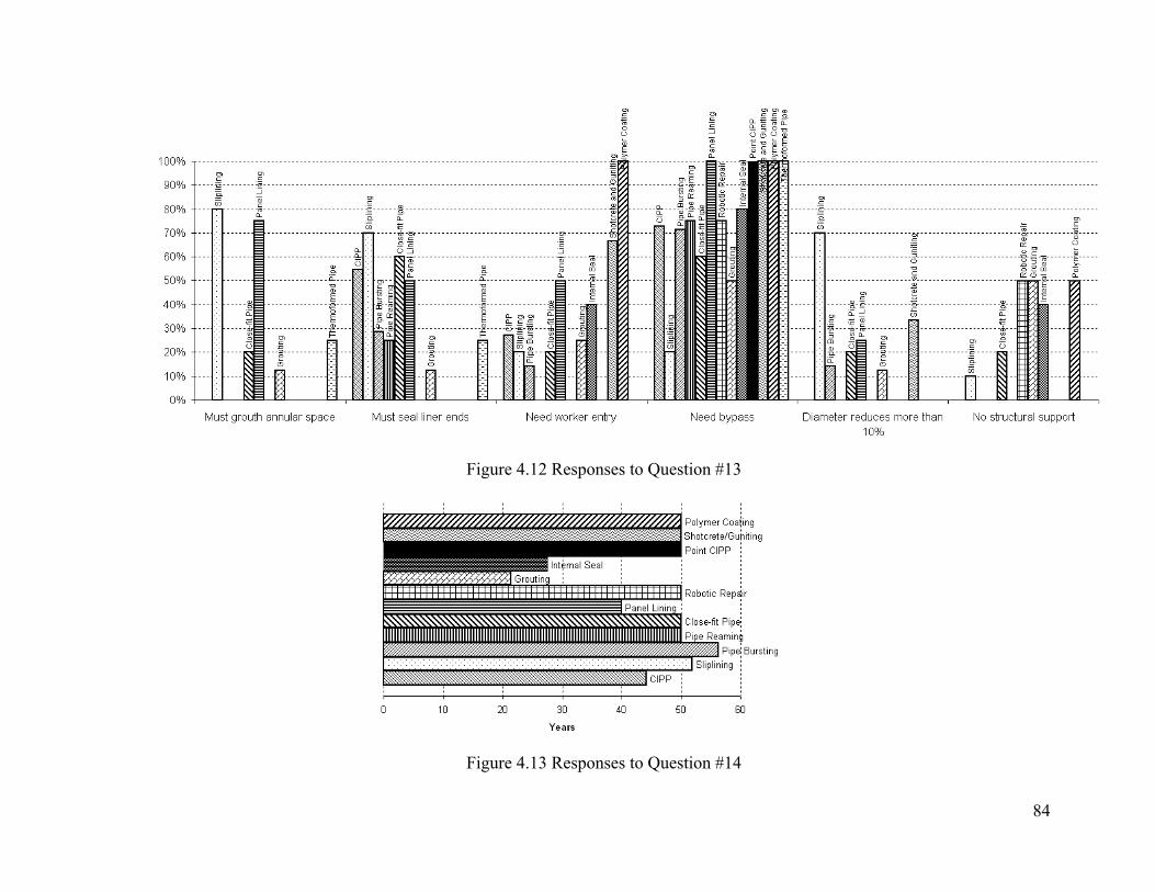
84
Figure 4.12 Responses to Question #13
Figure 4.13 Responses to Question #14
85
Question 15: Does your company typically perform any test on the renewal methods after
they are being applied to the existing deteriorated culvert?
Tests on the trenchless renewal methods are frequently used by companies as a quality
control measure. Some of the respondents indicated that they do not carry out any type of tests,
however the reader must take into account that the test might be carried out by other
subcontracted companies. Another surveyed company, indicated that they use several techniques,
such as: physical properties, hydraulic tests and Closed Circuit Television (CCTV) for the
Cured-in-Place Pipe, hydraulic tests and CCTV for sliplining as well for pipe bursting; air tests
and CCTV for grouting and CCTV for point CIPP.
Question 16: Which of the trenchless renewal methods are suitable for the following
problems executed in the culvert?
One of the main focuses of this report is to suggest a method to renew culvert and storm
sewers given a set of problems. This question inquires the surveyed companies to suggest a
Trenchless Renewal Method to be used in a summarized list of problems. On average, companies
believe that pipe bursting and robotic repair methods are suitable to renew culverts with all the
defects given in the list below. The survey also found that for a culvert which is affected by seam
defects and scalling the use of internal seal is highly suitable. A highlighted finding in this
question is that; CIPP and sliplining techniques is not suitable for renewing culverts affected by
misalignment / joint separation problems.
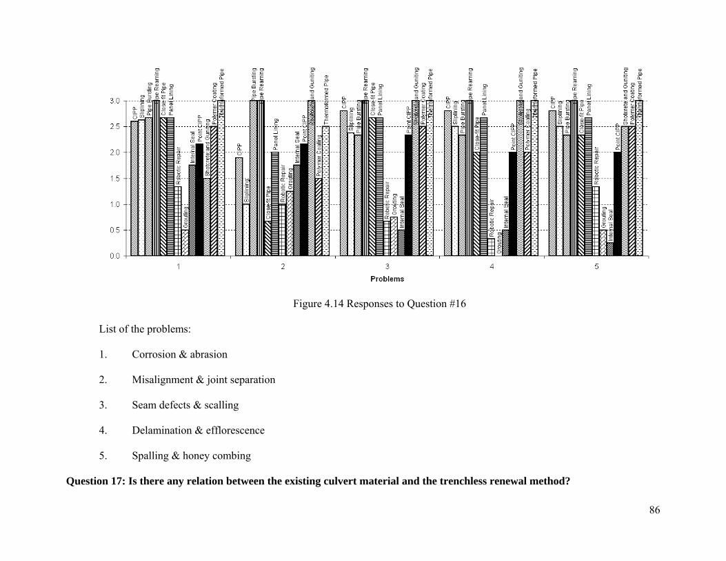
86
Figure 4.14 Responses to Question #16
List of the problems:
1. Corrosion & abrasion
2. Misalignment & joint separation
3. Seam defects & scalling
4. Delamination & efflorescence
5. Spalling & honey combing
Question 17: Is there any relation between the existing culvert material and the trenchless renewal method?

87
Question 17 mainly focused on the suitability of the trenchless renewal methods for a given existing culvert material.
According to the findings of the survey most of the renewal methods are suitable for concrete pipes; it is also notable that the grouting
technique is more suitable for concrete culverts compared to other type of materials. The results of the survey also show that close fit
pipe is highly suitable for concrete pipes and plastic pipes and the corrugated formations inside the steel pipe and the aluminum pipe
tend to discourage the use of close-fit pipe in renewal of culverts. For illustration purposes, number 3 was given to the most suitable
method and number 0 to the least suitable method. Figure 4.15 summarizes the outcomes of this question.
Figure 4.15 Responses to Question #17

88
Question 18: What specification and Material does your company use for Trenchless
Renewal Methods specifically for culvert applications?
This open answer question had a wide variety of responses; however, a general summary
will be provided in the following paragraphs:
Specifications:
• The study found that the industry standard “ASTM F1216” is used by companies to
renew culverts when using point CIPP and CIPP techniques.
• Previous company projects and the standard “AASHTO M326” are the specifications
used by companies to renew culverts when using Sliplining techniques.
• Previous company projects are commonly used as guideline specifications when
renewing culverts using pipe bursting.
• NASSCO standards are used in the Grouting renewal method.
Materials:
• For sliplining and pipe bursting, HDPE is widely used.
• PVC pipes are also used in sliplining renewal projects.
• When companies use CIPP or point CIPP techniques, they tend to use polyester (PE)
materials and combination of resin/felt as well.
• For the grouting renewal method, concrete is the material of choice.
Question 19: Please use this space additional information to be considered in our study.
Also please explain if your company uses any other type of Trenchless Technology.
From all the responses there was not a worthwhile response to this question.

89
5. Trenchless Technology Methods
Construction and renewal (rehabilitation and replacement) of buried pipes have been
performed traditionally by the open-cut method. This method generally involves excavation of a
trench for the whole length of pipe, dewatering, placing bedding material, placing the pipe, and
finally backfilling and compaction. This method causes construction and renewal procedures to
be very expensive especially where the depth of excavation is high and in congested areas due to
managing the traffic by providing detours. Other costs of open-cut construction and renewal of
buried pipes involve items such as the costs due to damage to the existing pavement (and other
buried infrastructure if present), user costs due to the waiting time and detour traveling, potential
accident costs due to work-zones, and environmental damage.
Trenchless technology methods offer alternative methods for construction and renewal of
buried pipes in which construction of trenches and thereby problems associated with the open-
cut method are reduced if not eliminated. Some of the trenchless technology methods such as
tunneling, and pipe jacking have been used in construction of buried structures for over a century
however with the technological advancements in computer science, material science, and
mechanical improvements in construction equipments during the last two decades new trenchless
technology methods have been revealed to inspect, construct, repair and renew the existing
buried structures in a cost effective manner without disrupting the environment and users. (Najafi
2004)
Since the design and construction of highway infrastructure network, the number of
vehicles has increased tremendously and majority of these highway infrastructure elements are
on the verge of completing their design lives. Therefore construction of new buried conduits and
renewal of the existing ones are among the top priorities of highway agencies. Trenchless

90
technology methods for inspection, construction, repair and renewal of buried pipes are the most
powerful tools of managing these highway assets which eliminate the problems associated with
open-cut methods. In this section trenchless technology methods used for inspection,
construction, repair and renewal of buried pipes are going to be examined in more detail.
5.1 Trenchless Inspection
Inspecting buried pipes for assessing their current conditions is one of the most important
duties of highway and/or utility agencies since it affects the accuracy of the decisions made
regarding the renewal of the pipe. Depending on the inspection results the agency decides
whether to do nothing, or to perform point repairs, or to rehabilitate the whole length of the pipe,
or to completely replace the existing pipe. Therefore the accuracy of the inspection results
directly affects the accuracy of the decisions made.
Inspecting culverts manually by worker entry may not always be possible due to the size
of the culverts or due to the dangers associated with entering into the particular culvert. In these
situations relying on the outcomes of inspections made from inlets and outlets may result in
taking a wrong course of action due to some of the defects unforeseen by the inspector.
Trenchless inspection methods examined in this section help to assess the condition of buried
pipes for which the entry of the inspector is not possible or dangerous.
5.1.1 Closed-Circuit Television (CCTV) (Najafi 2004)
CCTV technique is the most commonly used technique to inspect the inner surface of
gravity sewer pipes. In order to use this method the existing flow within the pipe should be less
than 25 to 30 percent. CCTV provides the inspectors a video record of the pipe surface which
can be stored and viewed in the future. The history of using CCTV can be dated back to the
1950s (ISTT, 1990). With the technological advancements in the electronic devices during 1980s
91
the cameras used in CCTV applications became more durable and capable of providing detailed
data. Today there are two major methods of using CCTV to inspect sewers. First one is the use of
stationary cameras which are mounted at the manholes. This method can be used to detect
whether a mobile CCTV application is needed or not. The defects closer to the manhole are
detected easier compared to the ones farther away from the manhole. This process does not
require cleaning of the pipe to insert the camera therefore may cost less than mobile CCTV
however it is not effective in determining the defects behind obstructions. This method can be
used in sewers up to 24 ft long and 36 inches in diameter. Second CCTV method is the mobile
CCTV. This method involves inserting a camera mounted tractor in the sewer pipe. The tractor is
operated by an expert above ground. Mobile CCTV equipment can detect defects on the pipe
wall with pan and tilt or zoom capabilities however it cannot detect the defects below the
existing flow level. CCTV method helps identifying problems related to cracks, infiltration,
deformation, collapsed sections and missing bricks.
5.1.2 Ultrasonic Inspection (Najafi 2004)
Ultrasonic inspection (Sonar) is a method used to detect defects on the pipe surface when
the existing flow restricts the use of video inspection methods. It is mostly effective for the pipes
with flows greater than 75%. The theory behind this method is that; sound wave is sent to the
surface of the pipe and the reflecting wave is different if there is a change in the density of the
surface. This method is useful to detect cracks, voids and pits. Sonar devices can be attached to
CCTV equipment to complement its functions.
5.1.3 Totally integrated Sonar and CCTV System (Najafi 2004)
This method combines the advantages of CCTV and Sonar methods. Sonar device is
added to the bottom portion of the CCTV equipment to enable the inspector to detect the

92
problems under the flow level. This method is applicable for pipes having a flow level between
25% to 75% and greater than 24 inches in diameter.
5.1.4 Laser Based Scanning Systems (Najafi 2004)
Laser-Based Scanning Systems are useful to detect problems above the flow level. This
method is useful to examine the shape of the pipe and the defects on the pipe wall. This method
produces more detailed results compared to CCTV. Another advantage of laser-based scanning
compared to CCTV is that; the output of inspection is recorded and analyzed by a computer
automatically. Therefore human error associated with this method is less than the human error
associated with CCTV.
5.1.5 Sewer Scanner and Evaluation Technology (SSET) (Najafi 2004)
SSET is designed to overcome the limitations of CCTV. The main advantages of SSET is
the incorporation of side scan and position data to the forward view. Side scan enables the
inspector to examine the whole pipe wall with the same light and angle settings, thereby
eliminates the interpretation error of the operator. The side scan and forward view can be
combined to create a three dimensional profile of the pipe wall. The position data enables
accurate mapping data of the camera.
During the field data acquisition stage the camera does not need to be stopped to record
the defects encountered during inspection. The operator is only responsible for ensuring the
proper operation of the inspection gadget. Data analysis and interpretation can be managed by
using computer softwares.
5.1.6. Ground Penetrating Radar (Najafi 2004)
Ground Penetrating Radar (GPR) is used to detect the soil conditions behind the pipe
wall. Presence of voids or water behind the pipe wall due to infiltration or exfiltration may create
93
problems for the structural integrity of the buried pipes such as loss of soil support or differential
settlement. In this method radio waves are sent to the surrounding soil either from above the
ground or from within the pipe. When the waves hit an object with different conductivity and
dielectric constant some portion of these waves is reflected while the rest simply maintains its
original direction. This method is more effective in dry sand compared to wet sand and clays.
5.1.7 Wall Microdeflections and Natural Frequency of Vibration (Makar 1999)
These methods are used to identify the overall conditions of brick sewers. In the wall
microdeflections method a microdeflection is created on the wall surface and pressure is applied
to deform it. The deformation is examined for the change of position. If the microdeflection
shows one directional change or if the direction of deformation shows rapid changes then the
concrete or brick wall is damaged. Identifying the correct magnitude of the pressure is a major
difficulty of this method. This method is only applicable to rigid pipes.
Natural frequency of vibration method is also used to determine whether the pipe has the
required mechanical characteristics. The wall of the pipe is vibrated and the natural frequencies
are examined. A good wall should show a certain predetermined type of natural frequency. The
amount of water within the pipe and surrounding the pipe and the characteristics of the soil
around the pipe may affect the vibrations.
5.1.8 Impact Echo / Spectral Analysis of Surface Waves (SASW) (Makar 1999)
These methods are employed to examine large concrete and brick pipes. An object is
dropped on the pipe or a pneumatic hammer is used to create a controlled impact and the
generated surface waves are detected by the geophones placed on the pipe wall. Spectral analysis
of surface waves provides a more detailed examination by the use of additional sensors with
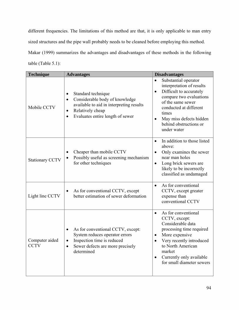
94
different frequencies. The limitations of this method are that, it is only applicable to man entry
sized structures and the pipe wall probably needs to be cleaned before employing this method.
Makar (1999) summarizes the advantages and disadvantages of these methods in the following
table (Table 5.1):
Technique Advantages Disadvantages
Mobile CCTV
• Standard technique • Considerable body of knowledge
available to aid in interpreting results • Relatively cheap • Evaluates entire length of sewer
• Substantial operator interpretation of results
• Difficult to accurately compare two evaluations of the same sewer conducted at different times
• May miss defects hidden behind obstructions or under water
Stationary CCTV
• Cheaper than mobile CCTV • Possibly useful as screening mechanism
for other techniques
• In addition to those listed above:
• Only examines the sewer near man holes
• Long brick sewers are likely to be incorrectly classified as undamaged
Light line CCTV • As for conventional CCTV, except
better estimation of sewer deformation
• As for conventional CCTV, except greater expense than conventional CCTV
Computer aided CCTV
• As for conventional CCTV, except: System reduces operator errors
• Inspection time is reduced • Sewer defects are more precisely
determined
• As for conventional CCTV, except: Considerable data processing time required
• More expensive • Very recently introduced
to North American market
• Currently only available for small diameter sewers

95
Technique Advantages Disadvantages
Laser scanning
• Very accurate defect and geometry measurements
• Computer based analysis • Digital data storage • Technique allows for accurate
comparison between evaluations conducted at different times Multiple evaluations would allow rates of damage to sewers to be determined
• Evaluates entire length of sewer
• Not yet commercially available for use in large diameter sewers
• Only works above water line
• More expensive than conventional CCTV
Ultrasound
• Capable of measuring defects above and below water line
• Can store data directly on computer • Computer based analysis can be used to
eliminate operator error • Accurate comparisons between
evaluations at different times can be made
• Multiple evaluations would allow rates of damage to sewers to be determined
• Evaluates entire length of sewer
• Very difficult to identify areas of cracking
• Thorough cleaning of sewer necessary for accurate measurements
• Somewhat more expensive than conventional CCTV
Microdeflections
• Not affected by bedding condition • Can be used to evaluate entire length of
sewer line • Provides direct measure of pipes
structural integrity • Available in mobile form for entry in
600 x 900-mm sewers
• Rigid pipes only • More expensive than
CCTV • Will not necessarily
locate individual defects
Natural vibrations
• Can produce evaluation of structural condition of sewer
• Can be used to evaluate entire length of sewer line
• Possible able to give condition of section of sewer without travelling its entire length
• Available in mobile form for entry in 600 x 900-mm sewers
• Effect of water inside pipe unknown
• Effect of bedding condition unknown
• Effect of specific defects unknown
• More expensive than CCTV
• Will not necessarily locate individual defects
• May require thorough cleaning

96
Technique Advantages Disadvantages
Impact echo
• Can produce evaluation of structural condition of sewer
• May detect voids behind sewers • Known to work in brick, concrete water
lines • Can be used to evaluate entire length of
sewer
• Results likely to combine pipe wall and bedding behaviors
• Currently only available in form of manually operated equipment
• More expensive than CCTV
• Will not necessarily locate individual defects
• May require thorough cleaning
SASW
• As impact echo, except frequency analysis allows separation of response from pipe wall and bedding
• Currently only available in form of manually operated equipment
• More expensive than CCTV
• Will not necessarily locate individual defects
• May require thorough cleaning
GPR from surface
• Does not require entry into sewer • Theoretically capable of detecting voids
near sewers
• Highly dependent on soil conditions
• No evidence of consistent ability to detect voids
• Tests have produced false positive results
• Substantial operator interpretation of results is necessary
GPR from inside pipe
• Detection of voids, rocks, and other objects in bedding
• Detection of exfiltration • Can detect delaminations in pipe walls • Otherwise not influenced by sewer
condition
• More expensive than CCTV
• Field tests required to prove technique
• Substantial operator interpretation of results is necessary
Table 5.1 Advantage and Disadvantages of Inspection Methods (Makar 1999)

97
5.2 Trenchless Construction
Trenchless construction of buried pipelines under roadways includes procedures in which
the pipe is installed without constructing large trenches which disrupt the traffic, pavement and
environment. Excavation may be required only to construct the access shafts and reception shafts
in order to install the pipes whereas in some methods the procedure may be performed above the
ground without the need of constructing shafts.
According to the NCHRP Synthesis of Highway Practice No.242, Trenchless Installation
of Conduits Beneath Roadways, trenchless construction methods can be divided into two major
categories as techniques that do not require personnel entry (horizontal earth boring) and as
techniques that require personnel entry during construction (pipe jacking and utility jacking)
(Iseley and Gokhale 1997). There are several different methods which fall under these two
categories. Table 5.2 which is taken from this NCHRP Synthesis of Highway Practice (No.242)
summarizes the descriptions of each method. These methods are further going to be examined in
detail in the following sections.
Method Type Method Description 1. Techniques Not Requiring Personnel Entry - Horizontal Earth Boring
Auger Boring
A technique that forms a bore hole from a drive shaft to a reception shaft by means of a rotating cutting head. Spoil is transported back to the drive shaft by helical wound auger flights rotating inside a steel casing that is being jacked in place simultaneously. Auger Boring may provide limited tracking and steering capability. It does not provide continuous support to the excavation face. Auger boring is typically a 2-stage process (i.e., casing installation and product pipe installation).
Slurry Boring
A technique that forms a bore hole from a drive shaft to a reception shaft by means of a drill bit and drill tubing (stem). A drilling fluid (i.e., bentonite slurry, water, or air pressure) is used to facilitate the drilling process by keeping the drill bit clean and aiding with spoil removal. It is a 2-stage process. Typically, an unsupported horizontal hole is produced in the first stage. The pipe is installed in the second stage.
Microtunneling
A remotely controlled, guided pipe jacking process that provides continuous support to the excavation face. The guidance system usually consists of a laser mounted in the drive shaft communicating a reference line to a target mounted
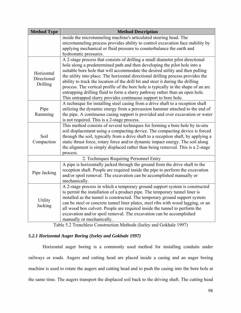
98
Method Type Method Description inside the microtunneling machine's articulated steering head. The microtunneling process provides ability to control excavation face stability by applying mechanical or fluid pressure to counterbalance the earth and hydrostatic pressures.
Horizontal Directional
Drilling
A 2-stage process that consists of drilling a small diameter pilot directional hole along a predetermined path and then developing the pilot hole into a suitable bore hole that will accommodate the desired utility and then pulling the utility into place. The horizontal directional drilling process provides the ability to track the location of the drill bit and steer it during the drilling process. The vertical profile of the bore hole is typically in the shape of an arc entrapping drilling fluid to form a slurry pathway rather than an open hole. This entrapped slurry provides continuous support to bore hole.
Pipe Ramming
A technique for installing steel casing from a drive shaft to a reception shaft utilizing the dynamic energy from a percussion hammer attached to the end of the pipe. A continuous casing support is provided and over excavation or water is not required. This is a 2-stage process.
Soil Compaction
This method consists of several techniques for forming a bore hole by in-situ soil displacement using a compacting device. The compacting device is forced through the soil, typically from a drive shaft to a reception shaft, by applying a static thrust force, rotary force and/or dynamic impact energy. The soil along the alignment is simply displaced rather than being removed. This is a 2-stage process.
2. Techniques Requiring Personnel Entry
Pipe Jacking
A pipe is horizontally jacked through the ground from the drive shaft to the reception shaft. People are required inside the pipe to perform the excavation and/or spoil removal. The excavation can be accomplished manually or mechanically.
Utility Jacking
A 2-stage process in which a temporary ground support system is constructed to permit the installation of a product pipe. The temporary tunnel liner is installed as the tunnel is constructed. The temporary ground support system can be steel or concrete tunnel liner plates, steel ribs with wood lagging, or an all wood box culvert. People are required inside the tunnel to perform the excavation and/or spoil removal. The excavation can be accomplished manually or mechanically.
Table 5.2 Trenchless Construction Methods (Iseley and Gokhale 1997)
5.2.1 Horizontal Auger Boring (Iseley and Gokhale 1997)
Horizontal auger boring is a commonly used method for installing conduits under
railways or roads. Augers and cutting head are placed inside a casing and an auger boring
machine is used to rotate the augers and cutting head and to push the casing into the bore hole at
the same time. The augers transport the displaced soil back to the driving shaft. The cutting head
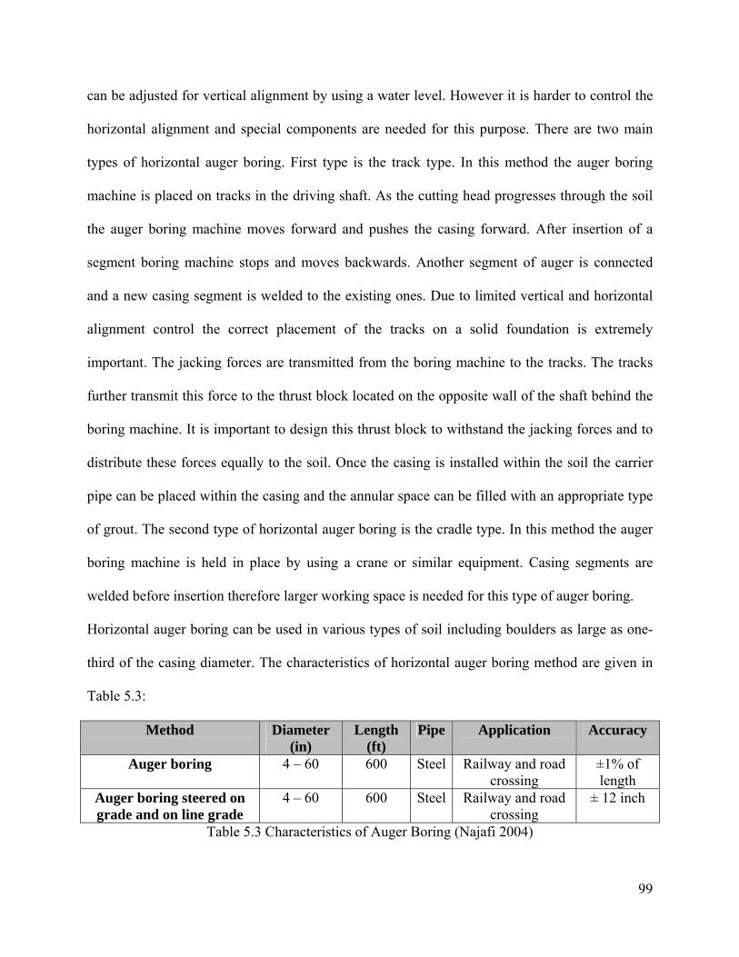
99
can be adjusted for vertical alignment by using a water level. However it is harder to control the
horizontal alignment and special components are needed for this purpose. There are two main
types of horizontal auger boring. First type is the track type. In this method the auger boring
machine is placed on tracks in the driving shaft. As the cutting head progresses through the soil
the auger boring machine moves forward and pushes the casing forward. After insertion of a
segment boring machine stops and moves backwards. Another segment of auger is connected
and a new casing segment is welded to the existing ones. Due to limited vertical and horizontal
alignment control the correct placement of the tracks on a solid foundation is extremely
important. The jacking forces are transmitted from the boring machine to the tracks. The tracks
further transmit this force to the thrust block located on the opposite wall of the shaft behind the
boring machine. It is important to design this thrust block to withstand the jacking forces and to
distribute these forces equally to the soil. Once the casing is installed within the soil the carrier
pipe can be placed within the casing and the annular space can be filled with an appropriate type
of grout. The second type of horizontal auger boring is the cradle type. In this method the auger
boring machine is held in place by using a crane or similar equipment. Casing segments are
welded before insertion therefore larger working space is needed for this type of auger boring.
Horizontal auger boring can be used in various types of soil including boulders as large as one-
third of the casing diameter. The characteristics of horizontal auger boring method are given in
Table 5.3:
Method Diameter (in)
Length (ft)
Pipe Application Accuracy
Auger boring 4 – 60 600 Steel Railway and road crossing
±1% of length
Auger boring steered on grade and on line grade
4 – 60 600 Steel Railway and road crossing
± 12 inch
Table 5.3 Characteristics of Auger Boring (Najafi 2004)
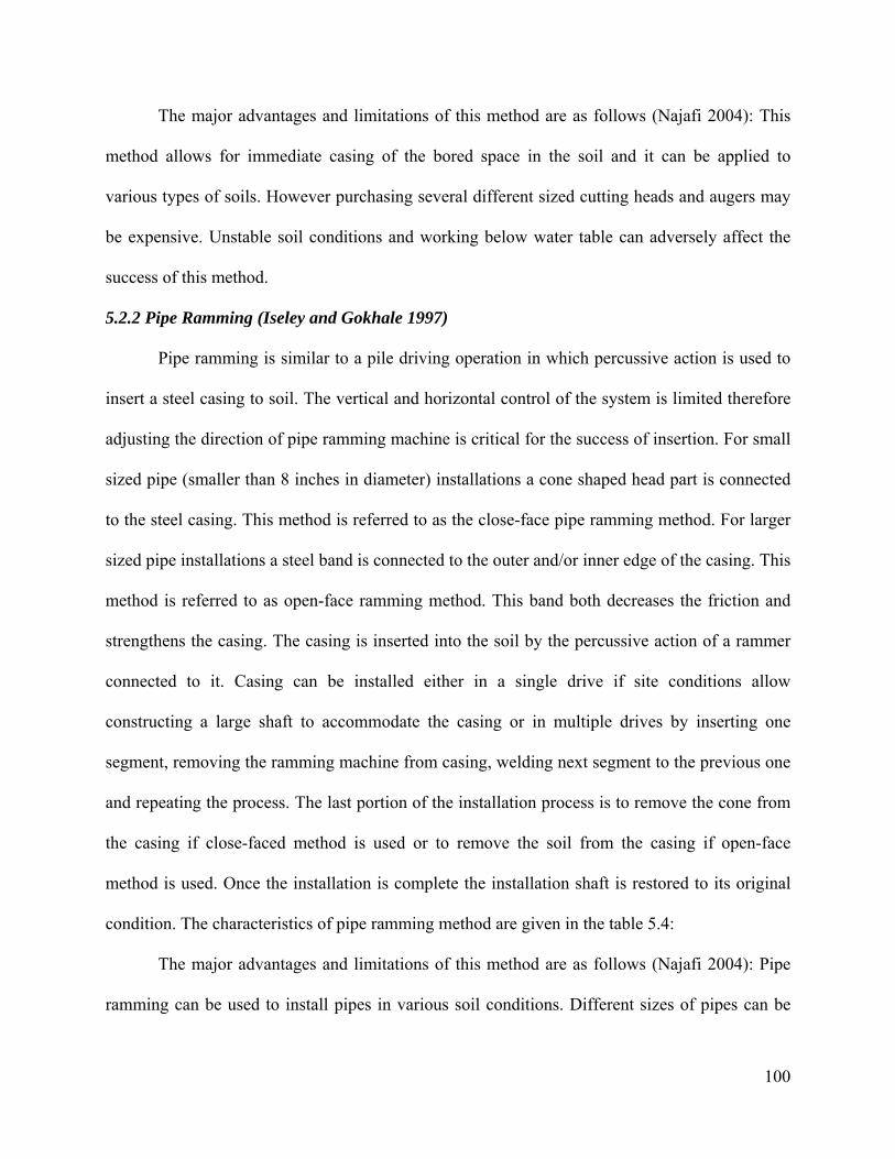
100
The major advantages and limitations of this method are as follows (Najafi 2004): This
method allows for immediate casing of the bored space in the soil and it can be applied to
various types of soils. However purchasing several different sized cutting heads and augers may
be expensive. Unstable soil conditions and working below water table can adversely affect the
success of this method.
5.2.2 Pipe Ramming (Iseley and Gokhale 1997)
Pipe ramming is similar to a pile driving operation in which percussive action is used to
insert a steel casing to soil. The vertical and horizontal control of the system is limited therefore
adjusting the direction of pipe ramming machine is critical for the success of insertion. For small
sized pipe (smaller than 8 inches in diameter) installations a cone shaped head part is connected
to the steel casing. This method is referred to as the close-face pipe ramming method. For larger
sized pipe installations a steel band is connected to the outer and/or inner edge of the casing. This
method is referred to as open-face ramming method. This band both decreases the friction and
strengthens the casing. The casing is inserted into the soil by the percussive action of a rammer
connected to it. Casing can be installed either in a single drive if site conditions allow
constructing a large shaft to accommodate the casing or in multiple drives by inserting one
segment, removing the ramming machine from casing, welding next segment to the previous one
and repeating the process. The last portion of the installation process is to remove the cone from
the casing if close-faced method is used or to remove the soil from the casing if open-face
method is used. Once the installation is complete the installation shaft is restored to its original
condition. The characteristics of pipe ramming method are given in the table 5.4:
The major advantages and limitations of this method are as follows (Najafi 2004): Pipe
ramming can be used to install pipes in various soil conditions. Different sizes of pipes can be
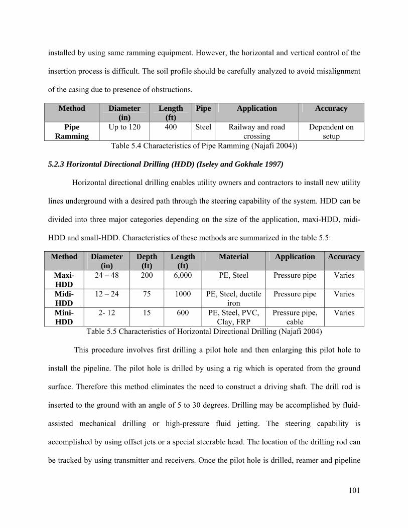
101
installed by using same ramming equipment. However, the horizontal and vertical control of the
insertion process is difficult. The soil profile should be carefully analyzed to avoid misalignment
of the casing due to presence of obstructions.
Method Diameter (in)
Length (ft)
Pipe Application Accuracy
Pipe Ramming
Up to 120 400 Steel Railway and road crossing
Dependent on setup
Table 5.4 Characteristics of Pipe Ramming (Najafi 2004))
5.2.3 Horizontal Directional Drilling (HDD) (Iseley and Gokhale 1997)
Horizontal directional drilling enables utility owners and contractors to install new utility
lines underground with a desired path through the steering capability of the system. HDD can be
divided into three major categories depending on the size of the application, maxi-HDD, midi-
HDD and small-HDD. Characteristics of these methods are summarized in the table 5.5:
Method Diameter (in)
Depth (ft)
Length (ft)
Material Application Accuracy
Maxi-HDD
24 – 48 200 6,000 PE, Steel Pressure pipe Varies
Midi-HDD
12 – 24 75 1000 PE, Steel, ductile iron
Pressure pipe Varies
Mini-HDD
2- 12 15 600 PE, Steel, PVC, Clay, FRP
Pressure pipe, cable
Varies
Table 5.5 Characteristics of Horizontal Directional Drilling (Najafi 2004)
This procedure involves first drilling a pilot hole and then enlarging this pilot hole to
install the pipeline. The pilot hole is drilled by using a rig which is operated from the ground
surface. Therefore this method eliminates the need to construct a driving shaft. The drill rod is
inserted to the ground with an angle of 5 to 30 degrees. Drilling may be accomplished by fluid-
assisted mechanical drilling or high-pressure fluid jetting. The steering capability is
accomplished by using offset jets or a special steerable head. The location of the drilling rod can
be tracked by using transmitter and receivers. Once the pilot hole is drilled, reamer and pipeline
102
is connected to the rod and pullback procedure starts. As Reamer expands the bore hole pipeline
is placed simultaneously. Due to high stresses applied to the pipe during installation steel pipes
are commonly used for HDD applications along with polyethylene pipes.
The major advantages and limitations of this method are as follows (Najafi 2004): The
steering capability is the major advantage of this method. Also construction of driving shafts is
not necessary which may lower the construction costs. The major limitation of this method may
be a potential danger of ground movement due to usage of pressurized fluids during drilling.
5.2.4 Microtunneling (Najafi 2004)
Microtunneling is a method of trenchless construction in which a remote controlled
microtunneling boring machine (MTBM) is used to cut the soil and a jacking system is used to
push the segments of the pipe and machine forward. A system for transporting the spoil and a
laser guidance system are the other important components of the microtunneling process. An
access shaft needs to be constructed in which the jacking system will be placed. Once the jacking
system is MTBM is lowered and placed on the jacking system. The MTBM starts cutting the soil
and the spoil is transported by a slurry mixture. The slurry is recycled once the spoil is removed
in the separation unit. Once the MTBM is jacked into the soil the jacks are retrieved and the new
segment of the pipe is lowered into the access shaft. The new segment is connected to the
previous one and the process continues until the MTBM reaches the receiving shaft. Once the
excavation and installation of the pipe is complete the MTBM is taken out of the receiving shaft.
The annular space between the excavated surface and the outer diameter of the pipe is grouted.
The characteristics of microtunneling method can be found in the Table 5.6:
Microtunneling method offers highly accurate installations of pipeline in any depth and
various difficult ground conditions. The disadvantage of microtunneling is the high initial cost of

103
the microtunnel boring machines. Microtunneling is not appropriate for low strength pipe due to
the jacking procedures involved. Obstructions in the soil profile may cause problems during the
cutting procedure.
Method Diameter (in)
Length (ft)
Material Application Accuracy
Microtunneling 10 – 136 500 - 1500
RCP, GRP, VCP, DIP, Steel, PCP
Gravity pipe
± 1 in
Table 5.6 Characteristics of Microtunneling (Najafi 2004)
5.2.5 Pipe Jacking and Utility Tunneling (Najafi 2004)
Pipe jacking and utility tunneling methods are similar to microtunneling except that these
methods require the worker to be involved in the installation procedure. Therefore these methods
are suitable for installing large diameter pipelines. Excavation can be performed by workers or
mechanical cutting devices inside a shield or tunnel boring machines. The procedure involves
construction an access shaft, lowering jacking equipment and inserting the cutting head and pipe
segments by jacking. The difference between the utility tunneling and pipe jacking methods is
that, in utility tunneling a liner is installed after excavation whereas pipe jacking the new pipeline
is installed to the excavated space. The main features of pipe jacking and utility tunneling are
summarized in the table 5.7:
Method Diameter (in)
Length (ft)
Material Application Accuracy
Pipe jacking and utility lining
42 and up 1500 RCP, GRP, Steel
Pressure and Gravity pipe
± 1 in
Table 5.7 Characteristics of Pipe Jacking and Utility Lining (Najafi 2004)
Some of the major advantages and limitations of pipe jacking are given as follows: This
method is applicable to almost any type of soil with a high accuracy. Due to the presence of
workers immediate corrective actions can be taken. The limitations of this method include
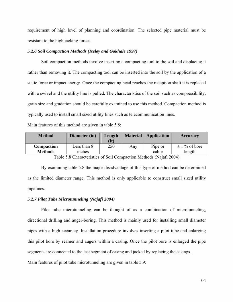
104
requirement of high level of planning and coordination. The selected pipe material must be
resistant to the high jacking forces.
5.2.6 Soil Compaction Methods (Iseley and Gokhale 1997)
Soil compaction methods involve inserting a compacting tool to the soil and displacing it
rather than removing it. The compacting tool can be inserted into the soil by the application of a
static force or impact energy. Once the compacting head reaches the reception shaft it is replaced
with a swivel and the utility line is pulled. The characteristics of the soil such as compressibility,
grain size and gradation should be carefully examined to use this method. Compaction method is
typically used to install small sized utility lines such as telecommunication lines.
Main features of this method are given in table 5.8:
Method Diameter (in) Length (ft)
Material Application Accuracy
Compaction Methods
Less than 8 inches
250 Any Pipe or cable
± 1 % of bore length
Table 5.8 Characteristics of Soil Compaction Methods (Najafi 2004)
By examining table 5.8 the major disadvantage of this type of method can be determined
as the limited diameter range. This method is only applicable to construct small sized utility
pipelines.
5.2.7 Pilot Tube Microtunneling (Najafi 2004)
Pilot tube microtunneling can be thought of as a combination of microtunneling,
directional drilling and auger-boring. This method is mainly used for installing small diameter
pipes with a high accuracy. Installation procedure involves inserting a pilot tube and enlarging
this pilot bore by reamer and augers within a casing. Once the pilot bore is enlarged the pipe
segments are connected to the last segment of casing and jacked by replacing the casings.
Main features of pilot tube microtunneling are given in table 5.9:

105
Method Diameter (in)
Length (ft)
Material Application Accuracy
Pilot Tube Microtunneling
6 – 10 300 RCP, GRP, VCP, DIP, Steel, PCP
Small diameter gravity pipe
± 1 in
Table 5.9 Characteristics of Pilot Tube Microtunneling (Najafi 2004)
The major advantage and limitation of this method is given as follows: Pilot tube
microtunneling offers very accurate installation of small diameter pipelines. However, this
method is applicable for installing pipelines in soft soil conditions since the pilot tube needs to be
inserted without replacing the soil.
5.3 Trenchless Repair and Renewal
Trenchless technologies can be used to repair, rehabilitate or to replace the existing
buried structures in a cost effective manner and without disrupting the users, pavement and
environment. In this report, renewal is used as a term to encompass rehabilitation and
replacement activities which are used to provide a new service life to the culvert.
Trenchless repair activities are those activities which do not provide a new design life to
the overall structure. They may be used to provide both structural and non-structural solutions
for the defected portions of the pipeline. In this chapter the repair activities are going to be
examined under the heading of “Point Source Repair” and “Invert Paving”.
Trenchless renewal activities provide a new design life to the pipeline by improving the
condition of the whole portion of the pipeline. Rehabilitation activities involve relining of the
pipelines or forming a new pipeline within the existing one. Cured-in-place pipe, sliplining,
close-fit pipe, thermoformed pipe, panel lining, underground coatings and linings, spiral wound
pipe and formed-in-place pipe are the trenchless rehabilitation methods which are going to be
covered in the following sections.
106
Trenchless replacement activities involve destruction of the existing pipe and installation
of a new pipeline with a same or greater diameter size to the same location of the existing one.
Pipe bursting and pipe removal are the trenchless replacement methods which are going to be
covered in the following sections.
5.3.1 Point Source Repair
Point source repair methods are used when a localized problem occurs in a buried pipe
which is structurally in good condition when the overall structure is considered. These methods
do not increase the design life of the structure however they offer structural and non structural
solution (depending on the method) to eliminate certain problems which may prevent the
structure from functioning with full capacity. Some of the common problems that may be
addressed by local repairs are joint problems, cracks, misalignment, etc.
Sometimes a buried pipe may exhibit several localized problems. In these cases it is
important to make economically feasible decisions whether to perform localized repairs or a
renewal method which will be applied to the whole pipe and extend its design life. Life cycle
cost analysis should be used by including any future maintenance costs associated with local
repairs and it should be compared with the cost of a more comprehensive renewal method.
Future plans regarding the location and surrounding area of the pipe should be kept in mind as
well. According to a practical rule localized repairs can be used if the pipe has defects on 25
percent or less of its length (Najafi, 2004). In the following sections some of the common point
source repairs will be examined in detail:
5.3.1.1 Robotic Repairs:
Robotic repair is mainly used to eliminate infiltration and cracks in gravity pipelines. The
robot first grinds and prepares the area of repair and then fills the area with epoxy mortar (Najafi
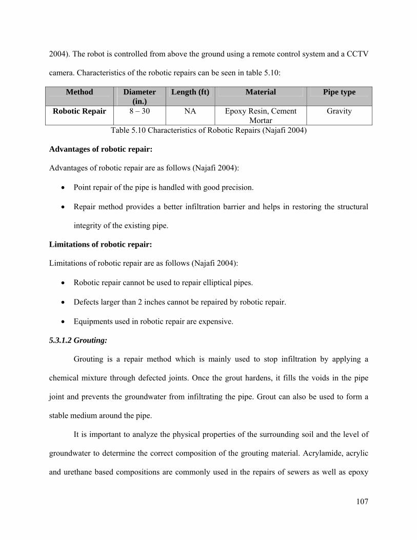
107
2004). The robot is controlled from above the ground using a remote control system and a CCTV
camera. Characteristics of the robotic repairs can be seen in table 5.10:
Method Diameter (in.)
Length (ft) Material Pipe type
Robotic Repair 8 – 30 NA Epoxy Resin, Cement Mortar
Gravity
Table 5.10 Characteristics of Robotic Repairs (Najafi 2004)
Advantages of robotic repair:
Advantages of robotic repair are as follows (Najafi 2004):
• Point repair of the pipe is handled with good precision.
• Repair method provides a better infiltration barrier and helps in restoring the structural
integrity of the existing pipe.
Limitations of robotic repair:
Limitations of robotic repair are as follows (Najafi 2004):
• Robotic repair cannot be used to repair elliptical pipes.
• Defects larger than 2 inches cannot be repaired by robotic repair.
• Equipments used in robotic repair are expensive.
5.3.1.2 Grouting:
Grouting is a repair method which is mainly used to stop infiltration by applying a
chemical mixture through defected joints. Once the grout hardens, it fills the voids in the pipe
joint and prevents the groundwater from infiltrating the pipe. Grout can also be used to form a
stable medium around the pipe.
It is important to analyze the physical properties of the surrounding soil and the level of
groundwater to determine the correct composition of the grouting material. Acrylamide, acrylic
and urethane based compositions are commonly used in the repairs of sewers as well as epoxy

108
resin and cement grouts (Najafi 2004). Pipes with small diameters which do not allow worker
entry may be repaired with remote controlled machines similar to the robotic repair. As an
advantage, grouting can effectively eliminate infiltration and exfiltration problems. As a
limitation this method should not be viewed as a structural solution and it should be considered
as a repair procedure for a pipe in good structural condition. The durability of the grout may be
considered as another limitation. The characteristics of grouting are summarized in Table 5.11.
Method Diameter (in.)
Length (ft) Material Pipe type
Grouting NA NA Chemical gel grouts, cement based grouts
Any
Table 5.11 Characteristics of Grouting (Najafi 2004)
Advantages of Grouting:
Advantages of grouting are as follows:
• Low cost.
• Infiltration and exfiltration problems can be eliminated with this method.
Limitations of Grouting:
Limitations of grouting are as follows:
• This method does not enhance the structural condition of the whole pipe.
• Durability of the grout is usually limited.
Grouting is a widely employed method to tackle infiltration problems in sewers. In the
following section some of the previous research studies and some case studies in which grouting
is chosen as a repair method will be covered:
Residents living in the southern New Castle County of Delaware were facing sewer
backup problems due to high level of infiltration in the SP-24 sewershed (Neidig and Shelton
2006). Test and seal method was used to repair joints and reduce infiltration. In this method,

109
joints are isolated and tested for leakage by using air pressure. If a joint fails the air test then
grout is applied to the joint to seal it. In this project a total of 67 pipe segments were tested and
sealed. The pipe sections had a diameter of 8 inches and they were made of PVC and VCP.
Characteristics of test and seal method are also discussed in this study. A comparison between
CIPP and test-and-seal method is presented. Test and seal method should be employed to prevent
infiltration in structurally sound structures. It is stated that if this method is applied properly it
can typically reduce the infiltration for a period of 10 years.
Grouting was used to repair the East Main Storm Sewer Pipe in the city of Woodland,
CA (Khan and Barnes 2004). The storm sewer was constructed in 1990 and it was made of 60
inch and 84 inch diameter unreinforced cast in place concrete pipe. Excessive infiltration through
the circumferential cracks caused roadway failures and expensive pipe repairs. Several different
trenchless renewals methods were also suggested for different segments of the pipe. CCTV
inspection and physical inspections were carried out. The cracks in the pipe were divided into
three categories depending on their severity. The effectiveness of the grout was tested on 5
circumferential cracks before finalizing the design. During the test it was determined that sealing
one crack affected other cracks which were not sealed yet. It was decided to perform a second
round of grouting. Sealing of cracks was performed by applying polyurethane based chemical
grout with hand held nozzles. The repair procedure started from upstream and continued toward
downstream. This project showed that it is important to inspect the pipe after sealing the cracks
since formation of new infiltration points due to the changes in groundwater level is possible.
5.3.1.3 Internal Seal:
Internal seal method offers structural solutions where a segment of the pipe or a pipe joint
fails. It can be used for both nonworker entry pipes as small as 6 inches and worker entry pipes

110
as large as 110 inches (Najafi, 2004). It is important to prepare the surface of the damaged area
to ensure proper adhesion with the sealing sleeve. The main characteristics of the internal seal
procedure can be seen in Table 5.12.
Method Diameter (in.)
Length (ft) Material Pipe type
Internal Seal 6 - 110 NA Special Sleeves Any Table 5.12 Characteristics of Internal Seal (Najafi 2004)
Advantages of Internal Sealing:
Internal sealing method offers the following advantages (Najafi 2004):
• This method offers structural solutions.
• This method can be applied to solve problems such as pipe breakage, joint settlement and
longitudinal cracks.
• Gravity sewers, culverts, and pressure pipes can be repaired without excavation.
Limitations of Internal Sealing:
Internal sealing method has the following limitations (Najafi 2004):
• Internal sleeve may cause a hydraulic loss due to decreased cross sectional area.
• This method is applicable to circular pipes.
5.3.1.4 Point Cured-in-place-pipe (CIPP):
Point CIPP method provides a structural solution to repair a failed section of a pipe. The
methodology of point CIPP is similar to the CIPP renewal method in which the whole pipe is
being renewed. The lining material is applied to the desired location by the use of an inflatable
packer and cured by the use of hot water or steam. (Najafi 2004) The liner should not be heated
before it is pressured to the surface of the existing pipe. The main characteristics of Point CIPP
method is given in Table 5.13.

111
Method Diameter (in.)
Length (ft) Material Pipe type
Point CIPP 4 -60 50 Fiberglass, polyester, etc. Gravity Table 5.13 Characteristics of Point CIPP (Najafi 2004)
Advantages of Point CIPP:
Point CIPP method offers the following advantages (Najafi 2004):
• Defected pipe sections between 3 ft and 50 ft of length with diameters up to 60 inches
can be repaired.
• Point CIPP adheres to the existing pipe tightly and eliminates infiltration.
• The repair procedure may usually be performed without diverting the existing flow.
• This method offers structural solution to the defected pipe segment.
• Lining does not obscure the flow due to tapered smooth ends.
Limitations of Point CIPP:
Point CIPP method has the following limitations (Najafi 2004):
• This method does not improve the structural condition of the pipe as a whole.
• Point CIPP method may be more expensive than other point source repairs.
• Hydraulic capacity may be slightly decreased due to lining.
5.3.2 Invert Paving
Invert paving is a common procedure to protect deteriorated inverts of culverts from
further deterioration due to corrosion and abrasion. If the deterioration has reached to a point
where the loss of material from the invert section is endangering the structural integrity of the
culvert, reinforcing steel should be welded while paving the invert. Various concrete types such
as Portland cement concrete, steel fiber reinforced concrete, high strength concrete…etc can be
used for invert paving procedures.

112
The detailed explanation of invert paving procedure can be found in FHWA’s Culvert
Repair Practices Manual Volume 2 (1995). According to this manual, the procedure starts with
diverting the flow. Water flow to the culvert should not be allowed until the concrete cures for 48
hours. The culvert should be cleaned thoroughly and the reinforcing steel should be placed on the
culvert. The amount of the reinforcing steel to be placed should be adequate to restore the
structural strength of the culvert. Concrete should be placed on the invert covering an adequate
percentage of the cross sectional area depending on the geometry of the culvert. Finally the
surface of the pavement should be smoothened and concrete should be properly cured before
returning it to the service.
The main characteristics of the invert paving procedure can be found in Table 5.14:
Method Diameter (in.)
Length (ft) Material Pipe type
Invert Paving More than 48 in.
NA Concrete (Portland Cement, steel fiber
reinforced concrete, etc.)
Gravity
Table 5.14 Characteristics of Invert Paving
Advantages of Invert Paving:
The advantages of invert paving procedures are as follows:
• Cost of repair is low.
• No need for special equipment.
Limitation of Invert Paving:
The durability of the paved section is usually limited.
5.3.3 Cured in Place Pipe (CIPP)
Cured in Place Pipe (CIPP) is one of the most commonly employed buried pipe renewal
methods. It was developed by Insituform in 1971 in the United Kingdom and brought to the U.S.
market in 1977 (Najafi 2004). This method is applicable to a very wide range of pipe types

113
including pipes with non circular shapes, bends and varying vertical alignments. CIPP offers
both structural and nonstructural solutions. CIPP must be designed according to the needs of the
renewal site at hand. Each job site should be handled separately and the design specifications
should be prepared and ordered after examining the original deteriorated pipe. Details of the
cured-in-place pipe renewal procedure can be found in ASTM F1216 07b (installation by
inversion) and ASTM F1743-96 (installation by pulling in place) standards.
Thermosetting resin and the fabric tube constitutes the major parts of the cured in place
pipe. The resin provides the necessary structural strength to the pipe. Unsaturated polyester,
vinyl ester and epoxy are among the most commonly used materials for CIPP resins (Najafi
2004). The fabric tube is used to hold the resin during the installation process. Summary of the
characteristics of CIPP method is given in Table 5.15:
Method Diameter (in) Max. length (ft)
Liner Applications
Inverted in place
4 – 108 3000 Thermoset resin / fabric composite
Gravity and pressure pipelines
Winched in place
4 – 108 1500 Thermoset resin / fabric composite
Gravity and pressure pipelines
Table 5.15 Characteristics of Cured-in-Place-Pipe (Najafi 2004)
As of 2008, a large majority of CIPP installed has used the hydraulic pressure of water to
install the CIPP tube and heated water to cure heat-initiated resin. During the hot water cure
cycle, small amounts of organic chemicals such as styrene can leach into the cure water. This hot
water cure process is generally acceptable in sanitary sewers because the waste process water can
safely be discharged to the sanitary sewer system when cooled. However, this waste process
water should not be discharged to the environment. Thus, if water is used to install and cure
CIPP for culverts or storm sewers, the waste process water must either be pumped to an adjacent

114
sanitary sewer system or hauled to a suitable disposal site. Depending on the project location and
logistics, this process can be cost prohibitive. Many rural culverts are long distances from water
sources and suitable cure water disposal sites. As a result, water must be hauled to the job site,
used during the installation, and then collected and hauled away from the job site to a suitable
disposal location. These additional costs can yield a project not cost-effective.
CIPP Procedure:
The steps of cured in place pipe renewal method are as follows:
• Cleaning the existing pipe
• Preparing the CIPP
• Installing CIPP
• Curing
Cleaning the existing pipe:
In this step the existing pipe should be cleaned completely in order to prevent
irregularities in the finished CIPP and ascertain that the new pipe will fit tightly to the existing
pipe in the installation step. During the cleaning procedure the characteristics of the new CIPP,
such as the diameter, length, and thickness, should be determined accurately by examining the
existing pipe.
Preparing the CIPP:
Once the design of the CIPP is completed it should be prepared for installation. This
preparation includes saturating also called impregnating the flexible tube with the thermosetting
resin. This step is crucial in achieving a successful renewal since if the CIPP is not saturated
properly, the new pipe will not have a tight fit to the existing pipe.
Installing CIPP:

115
The impregnated tube can be installed by either water inversion, compressed air inversion
or the winch method. Water inversion and compressed air inversion methods force the
impregnated tube to be inverted inside out through the length of the pipe to be renewed. The
winch method involves pulling the CIPP liner into its place and inflating the liner to fit into the
existing pipe. During the installation process care must be given to ensure a tight fit with the
existing pipe and liner is not damaged.
Pull-in and Invert Through is a method of installing CIPP which combines the two types
of installation. Wall thickness design and installation of CIPP utilizing the pull-in and invert-
through process is described in ASTM F 1743 (ASTM 2003). Two CIPP tubes are required for
this process. Once the host pipeline has been cleaned and prepared, the CIPP tubes are saturated
with liquid thermosetting polyester resin or wet out. Typically the bulk of the finished wall
thickness, and, thus, resin is placed in the tube that is pulled-in (Tube A). The inverted tube
(Tube B) may include a thin layer of fabric to be wet out. Or, it can simply be a bladder material
with no fabric, requiring no wet out (ASCE 2008)
First, Tube A is pulled into place. Tube B is then inverted with air through Tube A. This
process inflates Tube A and holds it in place tight against the host pipeline. Steam is then
introduced to cure the resin. If Tube B included a fabric material that was wet out, Tube A and
Tube B cure together forming one laminate. If Tube B is simply a bladder material with no wet
out fabric, it is typically extracted and discarded. With this process the resin is contained
between an outer and inner membrane or coating during the cure process thus minimizing the
chance that any liquid resin will escape into the environment.
This process is advantageous for difficult to access locations. Tube A which has a larger
wall thickness can be lowered in with a crane and pulled-in with a cable and winch. Air inverting

116
smaller sized Tube B is much easier and does not require the large set-up area when compared to
inverting only one tube that has the desired wall thickness (Thickness of Tube A plus thickness
of Tube B).
Curing:
Once the CIPP liner is installed into the existing pipe, it needs to be cured by water,
steam or UV light. During water and steam curing controlling the temperature is important to
achieve a successful renewal. Sudden drops in temperatures should be avoided. Once the new
CIPP is cured and cooled, the ends of the pipe can be opened. The interior of the new pipe
should be examined for any installation problems.
Quality Assurance and Quality Control
The contractor installing the CIPP should take quality assurance measures during the
installation process to ensure that quality controls listed in the contract documents are met. This
process is more easily accomplished if the contactor has a permanent quality program in place.
The testing requirements to determine if the installed CIPP meets the performance
requirements of the contract documents are typically listed in the technical specifications. Also,
the basic testing requirements outlined in ASTM F 1216, ASTM F 1743 and ASTM D 5813 are
applicable to storm sewers and culverts. These include:
• Workmanship: This includes a visual inspection for dry spots, lifts, delaminations or
other defects. This inspection is by closed-circuit-television (CCTV) for small pipes or a
walk-through on larger storms sewers or culverts.
• Flexural Properties: Flexural strength and flexural modulus are determined from a CIPP
sample collected at the jobsite. These values should meet or exceed the values specified.
117
• Wall Thickness: The in-place wall thickness should meet or exceed the specified
minimum wall thickness including any +/- tolerances.
• Chemical Resistance: Although chemical resistance properties are not as important in a
storm sewer or culvert as compared to a sanitary sewer, the materials installed should
meet the requirements of the chemical resistance test in ASTM F 1216.
• Tensile Strength: Tensile strength testing is not required for CIPP used to renew storm
sewers, culverts or sanitary sewers. Tensile testing is required only for pressure CIPP.
Conformance to performance-based requirements is a true indication of the installed
CIPP’s ability to perform satisfactorily over the expected design life of the project. Strict means
and methods specifications can be restrictive and exclusive because there are several types of
CIPP installation methods and numerous CIPP installers in the marketplace.
Inspector’s qualifications and responsibilities also determine how the final CIPP
installation is performed. The inspector must become thoroughly familiar with the contract
documents for the project and most importantly the detailed specifications. The detailed
specifications guide the inspector to the areas where the trenchless project must be inspected,
recorded, documented, tested and otherwise verified to ensure that the product is being installed
as specified (NASSCO 2007).
Among some of the quality control procedures, it is recommended by the ASTM D5813
that for each inversion designated by the owner, a specified number of CIPP samples must be
required. The sample should be cut from a section of the CIPP at the termination point that has
been inverted through. If the CIPP is used to repair large diameter culverts, the sample should be
fabricated from material taken from the tube and the resin/catalyst system used and cured in a
118
clamped mold placed in the tube when circulating heated water is used and in the silencer when
steam is used (NASSCO 2007).
The finished CIPP should be continuous over the entire length of the culvert and be free
of dry spots, lift, and de-lamination. If these conditions are present, the CIPP will be evaluated
for its ability to meet the applicable requirements of the contract documents. Where the CIPP
does not meet the requirements of the contract documents or specifically stated requirements of
the specifications, the affected portions of CIPP should be removed and replaced with an
equivalent repair (NASSCO 2007).
Advantages of CIPP:
The CIPP method offers the following advantages (Najafi 2004):
• CIPP eliminates the need for grouting due to the tight fit with the existing pipe.
• CIPP offers an improved flow capacity due to its smooth interior
• Pipes with noncircular shapes can be renewed without decreasing the flow capacity.
• CIPP can be used in renewal of pipes with bends and deformations.
Limitations of CIPP:
Some of the limitations of the CIPP method are as follows (Najafi 2004):
• The lining material must be specially designed for each project.
• The existing flow must be diverted.
• Liner pipe ends or lateral connections may have to be prevented against infiltration by
sealing.
• Monitoring, inspecting and testing of the curing process must be handled with great care.
• Removing the curing water from the job site may be a problem if pipe to be renewed is
not a sanitary sewer pipe.

119
• Lining can be affected by obstructions
Previous Research and Case Studies Related to CIPP
There have been several research studies related to the installation and performance of
CIPP due to the wide usage of the technique. In this section some of these important studies will
be discussed:
The Vallejo Sanitation and Flood Control District (VCFCD) chose the CIPP method to
renew the “North Interceptor” which was a 48-inch diameter reinforced concrete main sanitary
sewer pipe located 15 feet deep (Nelson et al. 2005). The interior pipe wall was seriously
deteriorated. Among the alternatives of open-cut replacement, sliplining, pipe bursting,
microtunneling and cured in place pipe (CIPP), CIPP was selected as the proper renewal method.
Open cut replacement was not suitable due to the site conditions and cost. Sliplining was not
suitable due to the decrease in cross section area. Pipe bursting was not feasible for the type and
size of the existing sewer pipe. Constructing a parallel line by microtunneling was not suitable
due to the cost and complexity. CIPP was selected as the best option due to minimum bypassing
time, and improved flow capacity. The execution of the project involved diverting the flow by
installing pumps, cleaning the pipe (high velocity water jet), inverting the liner (water inversion),
curing the liner (water curing), trimming the ends of the liner, and inspecting the finished
product. As a result this project is reported as a success due to the short project duration and
cost-effectiveness offered by the CIPP method.
Another CIPP application was performed during the renewal of Franklin-Main
Interceptor Sewer in the city of Columbus, Ohio (Siegfried and Coffey 2004). The three
segments of the sewer which have been renewed by using CIPP were made of 24” diameter clay
pipe in 1913. The depth of flow for segment 1 was between 3’ and 15’ with a total length of
120
1,867’. Segments 2 and 3 were 5,737’ in length. The section of segments 2 and 3 where the
sewer interceptor was passing below a river presented problems. The river water could wash
away the resin and affect the curing process due to its cold temperature. Grouting was thought as
a remedy to stop river infiltration but the high velocity of the infiltrating water made this option
impossible. Finally, it was decided to install pre-liner to prevent river water from infiltrating and
a thicker liner was chosen. The resin was also changed to improve its reaction time to curing. In
this project CIP manhole lining was utilized as well.
The city of San Jose used the CIPP method to renew a 42 inch diameter interceptor line
which was made of unlined reinforced concrete pipe (Ho and Pamintuan 2003). The CIPP
method was selected due to the presence of bends and the heavy traffic above the pipe and also
to minimize the capacity reduction of the renewed pipe. In some sections of the finished pipe
uplifts of the liner were observed. The reason of these uplifts was explained as the presence of
water pressure during the installation (inversion) of the liner. The flow was diverted at an
upstream location since the CIPP method does not allow renewing a pipe without fully diverting
the flow.
Another CIPP application was performed in Boston, Massachusetts while renewing the
South Charles River Valley Sewer (Pescatore 2007). This sewer line was constructed in 1895
and it had an oval shape with 54 inches width and 61.5 inches of height. Due to the populated
area and the existing utilities around the job site a trenchless method had to be selected. The
renewal was completed in three runs from two access points. First run started from the first
access point and it was 1550 ft long, second run started from the second access point and it was
2350 ft long in the backward direction, third run started from the second access point and it was
1550 ft long. Water inversion was used in this particular project. There were difficulties in terms

121
of controlling the temperature of the CIPP liner. Due to hot weather the liner hardened before
reaching the final destination.
A steam cured CIPP application was used to renew a 300 linear feet vitrified clay sewer
pipe in Portland, Oregon (Snyder 2004). The vertical alignment of the sewer pipe showed great
fluctuations, averaging 22% which lowered the number of replacement alternatives. As a result
CIPP lining with steam curing option was selected as the best available option. The final product
showed minor wrinkles at points where the vertical alignment changed however the steep slope
and smoother interior would eliminate this problem in terms of flow capacity.
Utility agencies may gain precious time by employing the CIPP method to renew a buried
pipe as in the case of the emergency renewal of a 30 inch diameter sewer pipe in the City of
Reno (Ablin and Stram 2005). The location of this highly deteriorated sewer pipe was very
sensitive against a potential spill due to the collapse of the pipe. The water inversion and water
curing of the CIPP lining enabled the renewal of the sewer pipe in only three weeks from
identifying the problem and completing the renewal.
The brick sewers in Newark, New Jersey are under an evaluation and rehabilitation
program since 1990. (Pennington et al. 2005). Water inverted and cured CIPP liners were used
extensively to restore the structural condition of these old and large sewers. Water inverted
linings were preferred due to higher quality achieved compared to the winch method and easier
installation around bends. Before the lining procedure started the voids were filled and any
ground water infiltration was stopped by injected acrylamide gel. The importance of the smooth
connection of laterals to the renewed sewer line was emphasized and application of rapid setting
epoxy mortar to achieve this connection was suggested.
122
Apart from the sewer pipes the CIPP method has also been employed to renew the water
distribution pipes. The city of Longueuil, QC, Canada is among the cities that select CIPP as a
convenient method to renew their water distribution network due to the following advantages:
(Fortin and Loiacono 2006)
• CIPP offers structural solutions while improving hydraulic capacity.
• CIPP can be applied for the renewal of water mains which are situated in urban
environments due to lesser amount of excavation needed.
• The installation procedure enables a quick return to normal operation of the water main.
• The CIPP method is cost effective compared to traditional methods.
• Social costs to the public are kept at a lower amount.
The water main pipe renewal is different than the renewal of a sewer pipe in terms of the
testing of the final product for hydrostatic pressure and disinfecting the pipe before it is reopened
for use.
The CIPP method has been applied successfully to structurally renew non circular,
rectangular box culverts (Tingberg 2007). One of the biggest advantages of CIPP over renewal
methods such as sliplining was given as the elimination of grouting the space between the new
pipe and the host pipe. Poor quality grouting procedures may cause piping and eventually loss of
soil support to the renewed structure. Working crew’s previous experience, preparation of the
host pipe, accurate examination of the project site and testing the renewal material were listed as
important factors which influence the success of the renewal project. The CIPP liners can be
impregnated in the factory or on the job site depending on the transportation requirements of the
liner to the jobsite. Some of the large rectangular culverts were converted into elliptical culverts
by using fillets in the corners. This was performed to ensure a full contact between the host pipe
123
and the CIPP liner. Even though this practice resulted in a decrease of the cross sectional area the
flow capacity was not affected to the smoother interior surface provided by CIPP liner. The
testing of the final product is important in terms of proving the resin was adequately impregnated
and the curing process was accomplished in accordance to the plans. The finished pipe should
also be tested against any voids behind the liner and fins on the surface of the liner. If any voids
are present the voids can be filled in by using curing resin, or epoxy or these sections of the
finished pipe can be cut and a point repair can be performed. The fins on the surface of the liner
may be eliminated by sanding.
In order to achieve long lasting renewal solutions by using CIPP owners should play
attention to several parameters (Kampbell 2005). These parameters can be divided into three
categories as the design phase, bidding phase and the construction phase. In the design phase the
condition of the existing pipe (whether it is partially deteriorated or fully deteriorated) and the
ground water level should be determined accurately as these factors influence the thickness of
the liner. During the bidding phase the experience of the bidders should be examined carefully.
During the construction phase the liner should be installed tightly to the existing pipe. The
ground water infiltration should be eliminated by stabilizing the surrounding soil. The thickness
of the finished product should be tested against the thickness in the plans.
It is very important to take samples from the field appropriately after the installation of
the CIPP liner (Lee and Ferry 2007). Relying on the results of specimens prepared in a
laboratory may not provide accurate results for a pipe installed and cured on the site. It may not
be a good strategy to rely on the manufacturer’s information neither. Therefore adequate number
of samples with appropriate lengths should be taken from the job site and tested in a laboratory
in order to justify the long term behavior of the renewed CIPP pipe.

124
The quality assurance and control practices play an important role in the long term
behavior of the CIPP liners. The mechanical properties of the liners can be affected by the
amount of moisture absorbed from the environment surrounding the liner. (Bakeer et al. 2004)
The city of Portland has been using the CIPP method to renew their buried pipes for
about 39 years (Braun 2006). According to their experience the method gave poor results under
certain circumstances. These circumstances were related to the presence of unexpected levels of
groundwater on the jobsite, faults in curing method and issues regarding the lateral reconnection.
These problems should be eliminated by proper design and installation procedures to have a
successful renewal project and to improve the quality of the final product.
Ground water infiltration may cause the bottom section of the CIPP liners to be lifted up
and also may cause the formation of ribs along the liner (Khan 2005). To eliminate these
problems a pre-liner may be installed. The boiler unit should be selected according to the
requirements of the job site. If the capacity of the boiler is not sufficient smaller sections of CIPP
liner should be installed. If the shape of the liner and the host pipe does not have a good match
fins and wrinkles may form on the liner. Fins can be grinded and coated with epoxy. Wrinkles
should be checked whether they are causing any structural deficiencies.
The problems associated with faulty CIPP applications may be categorized under three
groups: Aesthetic defects, operational defects and structural defects (Larsen et al. 2006). Small
irregularities on the surface of the liner such as small bumps and ribs which do not affect the
flow can be considered as aesthetic defects. These problems usually do not need to be corrected
and can be eliminated by using appropriately sized liners in the future. Larger bumps, ridges or
ribs which affect the flow can be considered as operational defects. Improper sizing and
installation, errors in lateral restoration or in grouting may cause operational defects. The liner
125
should be reinstalled partially or as a whole to correct operational defects. Problems such as
bulging and insufficient strength or thickness of the liner are among the structural defects which
may cause the failure of the liner. The liner has to be reinstalled partially or as a whole to correct
structural problems.
In the majority of the applications of CIPP styrene is emitted to the environment (Bauer
and McCartney 2004). Styrene is used in CIPP liners since it shortens the reaction time and it is
cost effective however it can also have adverse effects on the workers and public. Therefore a
program to eliminate the odor problem due to the styrene present in the liner would be beneficial.
National Association of Sewer Service Companies (NASSCO) has recently published a guideline
in which the use of styrene in CIPP pipe renewal was examined (2008). According to the
findings presented in this guideline styrene has not caused any serious health problems during
the timeframe it has been used in CIPP application. Since styrene can be detected even at very
low concentrations and due to lack of definitive documentation, speculations arose regarding its
effects on workers, public and environment arose. According to the guideline, typical CIPP
applications, in which styrene is used, emits 0.5 ppm styrene which is a low figure when
compared to the voluntary industry standard value of 50 ppm. Styrene has found to cause
reversible effects on central nervous systems at levels above 50 ppm. The guideline also provides
information on the proper procedures related to receiving and storing chemicals, handling resins,
and installation procedures for CIPP applications that contain styrene.
The renewal of large pipes by using CIPP method may be difficult due to the space
requirements of the equipment and liner during installation. Fiber-reinforced sandwich
technology can be used in the renewal of large pipes in order to decrease the thickness of the
liner and space requirements of the equipment in the installation process (Hahn 2007). Three
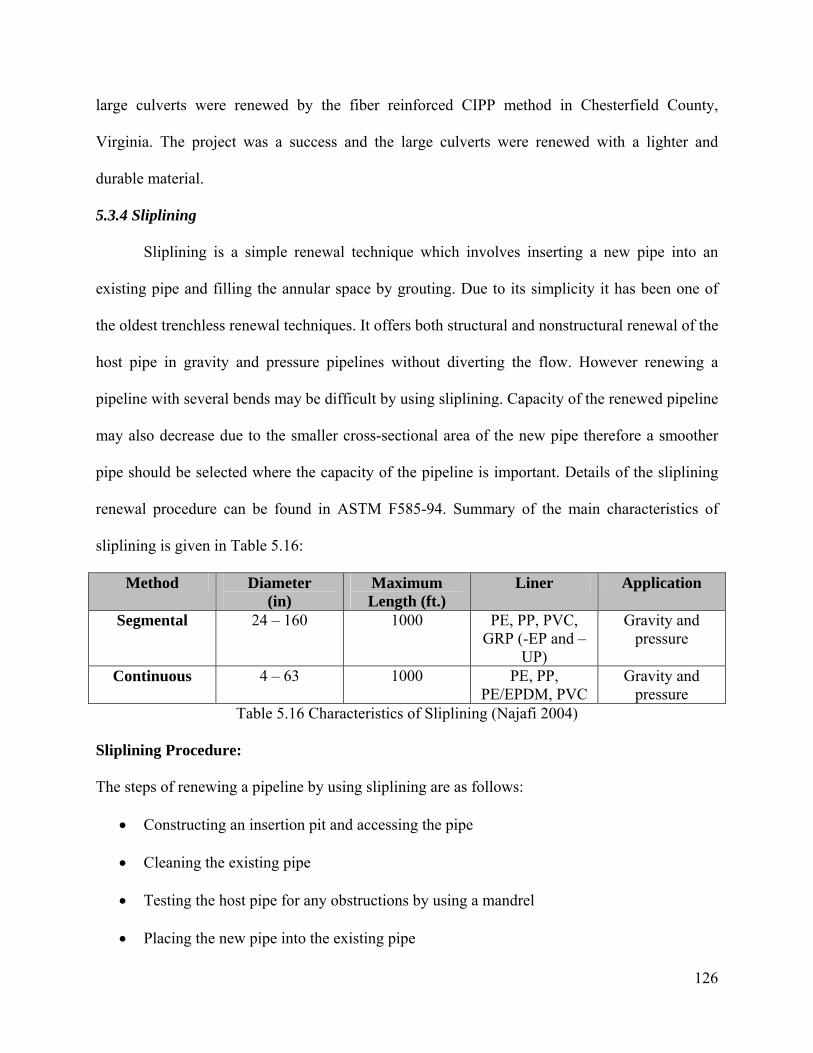
126
large culverts were renewed by the fiber reinforced CIPP method in Chesterfield County,
Virginia. The project was a success and the large culverts were renewed with a lighter and
durable material.
5.3.4 Sliplining
Sliplining is a simple renewal technique which involves inserting a new pipe into an
existing pipe and filling the annular space by grouting. Due to its simplicity it has been one of
the oldest trenchless renewal techniques. It offers both structural and nonstructural renewal of the
host pipe in gravity and pressure pipelines without diverting the flow. However renewing a
pipeline with several bends may be difficult by using sliplining. Capacity of the renewed pipeline
may also decrease due to the smaller cross-sectional area of the new pipe therefore a smoother
pipe should be selected where the capacity of the pipeline is important. Details of the sliplining
renewal procedure can be found in ASTM F585-94. Summary of the main characteristics of
sliplining is given in Table 5.16:
Method Diameter (in)
Maximum Length (ft.)
Liner Application
Segmental 24 – 160 1000 PE, PP, PVC, GRP (-EP and –
UP)
Gravity and pressure
Continuous 4 – 63 1000 PE, PP, PE/EPDM, PVC
Gravity and pressure
Table 5.16 Characteristics of Sliplining (Najafi 2004)
Sliplining Procedure:
The steps of renewing a pipeline by using sliplining are as follows:
• Constructing an insertion pit and accessing the pipe
• Cleaning the existing pipe
• Testing the host pipe for any obstructions by using a mandrel
• Placing the new pipe into the existing pipe
127
• Establishing the connection to the laterals
• Grouting the annular space
• Closing the pits
Constructing an insertion pit and accessing the pipe:
An insertion pit with an appropriate size should be excavated over the existing pipe. The
size of the insertion pit may depend on the depth of the pipe and the flexibility of the liner
material. The insertion pit for a sliplining procedure where a long segment of fused PE pipe is
used as a liner would have a larger size compared to the insertion pit required for a sliplining
procedure where small segments of the liner is connected to each other in the insertion pit. The
insertion pit should be water tight in order to reduce the exfiltration of the flow to the
surrounding soil once the existing pipe is accessed.
Cleaning the existing pipe:
The existing pipe should be cleared of any debris and obstruction in order to provide a
pathway for the liner pipe.
Testing the host pipe for any obstructions by using a mandrel
A mandrel which has the same exact size with the liner material should be inserted into
the existing pipe in order to test the pathway for the liner.
Placing the new pipe into the existing pipe
Once the preparation of the host pipe is finished the new liner should be placed inside the
host pipe before the formation of debris and accumulation which may obstruct the insertion of
the new pipe. The new pipe can be pushed or pulled into the existing pipe. Care must be given
not to damage the liner by applying excessive pressure.
Establishing the connection to the laterals
128
The laterals should be connected to the main pipe before grouting the annular space by
excavating and installing the connector segments.
Grouting the annular space:
The annular space between the new liner and existing pipeline should be grouted by using
an appropriate strength grout. The grout selection depends on the design of the new pipeline
system. If a bond is needed between the host pipe and the new liner is not capable of
withstanding the structural loading then using a cementitious grout would be appropriate. If the
grout is used only to transfer loads from the host pipe to the liner then a grout with strength of
stiff clay would be appropriate (Najafi 2004).
The floating of the liner should be avoided during the grouting process. The existing flow
escapes from the annular space with the application of the grout.
Quality Assurance and Quality Control:
• Verify liner pipe is undamaged from insertion and grouting by inspection via walk
through or video.
• Verify all joints are fully assembled by inspection via walk through or video.
• Verify liner pipe deflection is </= 5% (if some distortion is noticeable).
• If required, leakage test the installed by infiltration, exfiltration or air testing.
Advantages of Sliplining:
The Sliplining method offers the following advantages (Najafi 2004):
• Special expensive equipments are not needed.
• It is a simple method applicable to both gravity and pressure pipelines.
• It offers both structural and nonstructural solutions.
• This method allows for renewal without diverting the actual flow.
129
Limitations of Sliplining:
Some of the limitations of the Sliplining method are as follows (Najafi 2004):
• Pipe diameter is reduced as a result of sliplining
• A pit needs to be constructed.
• Laterals need to be connected by using open cut installation.
• The annular space generally needs to be closed by grouting.
Previous Research and Case Studies Related to Sliplining
There have been several research studies related to the sliplining renewal method due to
the simplicity and wide usage of this technique. In this section some of these important studies
will be discussed:
In Framingham, MA sliplining method was used to rehabilitate a 200 ft. long sewer pipe
located in the downtown area under a railroad (Wells and Cahill 2007). The presence of a rock
entering the pipeline from the surrounding soil further complicated the rehabilitation of the
pipeline. Using CIPP was eliminated since the presence of rock was a threat to the structural
properties of the CIPP liner. Pushing the rock outside was not possible since a remotely
controlled hydraulic jack would be expensive and could risk the structural properties of the pipe.
The rock could not be removed by excavation since it was located underneath the railroad tracks.
Pipe bursting was not possible for this rehabilitation project since the location of the pipe
restricted the size of the access pit that could be constructed. As a part of this rehabilitation
project a permanent by pass was constructed therefore the reduction in the cross sectional area
did not present any capacity problems and there were no lateral connections present on the sewer
pipe. Therefore sliplining the 18-inch sewer pipe with a 12-inch HDPE pipe was suitable for this
rehabilitation project. In order to decrease the size of the access pit it was decided to connect
130
pipe segments in the access pit before inserting them to the host pipe. The pipe segments were
ordered after measuring the size of the manhole from which the insertion would be performed. A
mandrel was run through the host pipe in order to assure the inserted pipe would fit in the host
pipe even in the presence of the rock. Pipe segments were lowered into the manhole and
connected to each other by using a chain wrench. The connected pipe segment was hydraulically
pushed inside the host pipe. Once the insertion was completed the annular space was filled. The
rehabilitation project was successful with no disruption to the public for a little cost.
Another sliplining project took place in the City of Los Angeles to rehabilitate a 3,200
feet long 42 inch brick sewer pipe (Jenson et al. 2003). The sliplining method was chosen since it
was not possible to divert the flow in the main line. In the pipe selection stage it was important to
choose a pipe with a large inner diameter and a small outside diameter in order to maximize the
flow capacity of the renewed pipe without risking the insertion procedure of the new pipe. The
pipe selected for this rehabilitation project was a CCFRPM pipe with an inner diameter of 36
inches and an outside diameter of 39 inches. The access pit was constructed with a size of 10
foot by 30 foot. The host pipe was cleaned by using winches and a sled. The cleaned pipe was
not tested by using a mandrel on this project however the sled used to clean the pipe was the
same size with the pipe to be inserted. The pipe was inserted while blocking a section of the
roadway at night time. Once the new pipe was inserted the laterals and chimneys were connected
to the main line and the annular space between the host pipe and the new pipe was grouted. As
the grout was injected to the annular space the water was pushed out. Therefore the sewer line
was rehabilitated without diverting or by passing the existing flow.
The City of San Jose decided to renew the 48-inch diameter reinforced concrete Forest
Rosa supplemental interceptor line with the sliplining method (Ho and Pamintuan 2003). The
131
new pipe was selected as a closed profile wall PVC. The insertion pit used for the sliplining
method was 20 feet (width) by 30 ft. (length). During the insertion process more sharp bends
were found than anticipated. The difficulty of inserting a new pipe in some of these sections was
overcome by building new manholes and using smaller segments of pipe. However for some of
the sections these solutions did not work and these sections were left for a future rehabilitation
project. The laterals were connected to the main line by using a trenchless method, namely the
top hot procedure wherever the open cut excavation was not possible.
The City of Gatineau, Quebec has used the sliplining method to renew 220 meters of
corrugated steel sewer pipe (Tardif 2003) located underneath a boulevard and also crossing a
railroad track. Two different types of pipes were selected for this project. A profile wall HDPE
pipe was used to renew 163 meters of the pipe and a solid wall HDPE pipe was used to renew the
remaining 57 meters of the pipe. The profile wall HDPE pipe had an inner diameter of 1200 mm.
and the solid wall HDPE pipe had an external diameter of 1350 mm. The existing pipe had a
bituminous coating when it was built but due to the abrasion of the flow the coating was
damaged. The cleaning process involved removing the any remaining coating from the existing
pipe. A mandrel was prepared to test the opening in the existing pipe. Skis which were made out
of cut portions from the new pipe were placed on the insertion pipe. Access pits were constructed
over the existing pipe. A fusion machine was used to connect two solid wall HDPE pipe
segments and the insertion was performed by using a shovel and a crane. The profile wall HDPE
pipe segments were lowered into the access pits and they were connected to each other by using
slings. The segments were inserted into the pipe one by one. The lateral connections were
performed by open cut excavation. The annular space between the new pipe and the old pipe was
132
grouted through the grouting holes every 3 meters. The skis kept the new pipe in place and
eliminated floating.
The city of Los Angeles used sliplining method to renew a 5,700 feet long tile lined
concrete sewer in Crenshaw District (Cho et al. 2003). The sewer line had a diameter of 75
inches and it was renewed by inserting a new pipe which had a diameter of 66 inches. The
sliplining method was selected since it was impossible to divert the flow within the pipe at any
time. Access pits were constructed where there were bends and angles. The existing pipe was
cleaned by using a steel cable and cylinders attached to winches. Once the cleaning was
complete the pipe was tested for obstruction by using three different mandrels. One of the
mandrels had the same external diameter with the new pipe and the others were 1 inch bigger
and smaller in external diameter respectively. An insertion machine was used to push the
segments of the CCFRPM pipe which were lowered into the access pit by a crane. The lateral
connections were established with the new pipe and the annular space between the old pipe and
the new pipe was grouted. The sliplining method presented some challenges to the public due to
the access pits constructed on narrow streets and odor problems however the public relations
were handled with care to eliminate complaints.
The city of Portland has been using sliplining as a renewal method since about 1990
(Braun, 2006). According to their experience sliplining can cause problems when the size of the
new pipe is not determined accurately, when there are excessive number of service lateral
connections and when the grouting place is not handled with care. If the size of the pipe to be
inserted into the existing pipe is close to the diameter of the existing pipe, the obstructions on the
existing pipe due to joint offsets may affect the sliplining process. Excessive number of service
lateral connection may cause the construction cost to increase due to the need of open cut
133
excavation and connection of lateral service lines. The grouting process may cause hydrostatic
pressure and damage on the existing pipe and the new pipe. The grouting procedure also may
cause flotation of the pipe and damage the lateral connections.
Sliplining was also used in the renewal of a storm drain in the city of Los Angeles
(Pickering et al. 2003). The storm drain renewed in this study was a 470 feet long arched
corrugated metal pipe. Due to an angle present along the drain the project was performed in two
parts. Downstream of the angle was renewed by man-entry installation and epoxy connection of
3ft long sections followed by grouting annular space. The first part of the project was renewed
by sliplining 6 ft long sections. Once all the sections were connected to each other by using
rubber gasket and gasket spigot and placed within the existing pipe the annular space was
grouted.
Minnesota Department of Transportation performed a study about sliplining deteriorated
culverts with a variety of materials in order to compare their constructability and costs with
open-cut methods (Johnson and Zollars 1992). The findings of this study are as follows:
• Smooth Polyethylene pipes had debonding problems due to differences in coefficients of
thermal expansion and due to the completion of grouting process in only one step (which
caused floating of the liner)
• Spiral Ribbed Polyvinyl Chloride had an inexpensive material cost but pushing ribbed
liner through the culvert was difficult. PVC exhibited brittle behavior in cold weather.
• Fiberglass liners had high material costs. Even though the installation was smooth,
pushing through corrugated metal exhibited problems. Fiberglass liners are quite heavy
which makes it difficult to handle compared to other liners.

134
• Installation of a Spiral Ribbed Coated Steel Arch was the most difficult and time
consuming. Ribs on the liner were caught on the rivets and corrugation on the older
culvert. Although it was the hardest to install, spiral ribbed coated steel arch provided the
least capacity loss.
5.3.5 Close-Fit Pipe
Close-fit pipe renewal method involves inserting a polyethylene pipe which has a
modified cross sectional area into a deteriorated pipe and returning the polyethylene pipe into its
original shape by pressurization. This method is generally employed in the renewal of
pressurized pipelines. There are two methods of close-fit renewal: mechanically folded liners
(MFP) and reduced diameter pipes (RDP) (Najafi 2004). In MFP process, the new polyethylene
pipe the cross section of the new pipe is changed into a U-shape by using a mechanical shaper
and temporary bands are used to keep the pipe in this shape until it is filled with water and
pressurized. In the RDP method the cross sectional area of the new pipe is modified either
mechanically by using mechanical rollers or thermally by using heat. Characteristics of close-fit
pipe renewal method are given in Table 5.17:
Method Diameter (in.) Length (ft) Material Pipe type Close-fit
Structural 3 – 24 1000 HDPE, MDPE Pressure, gravity
Close-fit Nonstructural
3 - 63 1000 HDPE, MDPE Pressure, gravity
Table 5.17: Characteristics of Close-fit Pipe (Najafi 2004)
Close-Fit Pipe Renewal Procedure:
The steps of close-fit renewal method are as follows:
• Cleaning the existing pipe
• Modifying the cross section of butt fused polyethylene pipes
• Inserting the modified polyethylene pipe

135
• Rerounding the polyethylene pipe
Cleaning the existing pipe:
In this step any accumulation and deposit in the existing pipe should be removed. The
existing pipe should also be inspected for any groundwater infiltration. If infiltration is present it
should be stopped by appropriate point repair options.
Modifying the cross section of butt fused polyethylene pipes:
Depending on the method of choice, MFP or RDP, the new polyethylene pipe should be
modified in cross section either mechanically or thermally. If MFP is used temporary bands
should be used to keep the new pipe in its deformed shape.
Inserting the modified polyethylene pipe:
The polyethylene pipe should be inserted to the existing pipe immediately after
modifying its cross sectional area. Excessive pulling forces may damage the new pipe during
insertion therefore new pipe should be lubricated whenever necessary.
Rerounding the polyethylene pipe:
Once the new pipe is inserted into the existing pipe the ends of the pipe should be
temporarily sealed and the new pipe should be filled with water. Once the pipe is filled with
water, the pipe should be rerounded by applying pressure. To achieve a successful fit between
the existing pipe and the new pipe the pressure should be maintained for the predetermined
amount of time.
Quality Assurance and Quality Control
• A final quality review should be performed to compare the completed renewal work with
the requirements of technical specifications and contract documents. A final review
136
would expose any variations of changes between the contract documents and the work of
the contractor.
• When a renewal project is completed, the contractor should provide the pipeline owner
with documentation of the quality of the work performed. In this respect, it is important
that requirements for such documentation be included in the bid documents. The
documentation should include the following:
o Information on the products and the installation method used.
o Pre and postinspection results.
o Test results
o Any changes or deviations from contract documents and possible corrective work
performed
o Information on service lateral reinstatements and pipe ends or manhole
connections and possible grouting process performed.
o Recommendations for future inspections, cleaning, maintenance, and other
renewal works to be completed as part of a comprehensive renewal work.
o Survey of residents, businesses and customers about the renewal project.
Advantages of Close-Fit Pipe:
The Close-fit pipe method offers the following advantages (Najafi 2004):
• The new polyethylene pipe used in renewing the existing pipe is produced in a controlled
environment.
• The cross sectional loss is minimal.
• This method is useful in eliminating internal corrosion problems.
• Pipes with bends up to 45 degrees can be renewed by MFP.
137
• Installations can be performed up to 1000 ft.
• It is possible to establish the lateral connections internally.
Limitations of Close-Fit Pipe:
Some of the limitations of the Close-fit Pipe method are as follows (Najafi 2004):
• Diameter range and length of installation are limited.
• The new butt-fused polyethylene pipe occupies a large space.
• Pipes with varying cross sectional area and large bends are not appropriate for this
method.
• In general, an insertion pit needs to be constructed.
• Usually the existing flow needs to be diverted.
• Valves and connections may require excavation.
Previous Case Study Related to Close-Fit Pipe
Close-Fit Pipe renewal method was employed during the renewal of a 600 meter long
pressure sewer pipe in Berlin, Germany (Singer 2006). Cold swage lining method was preferred
to renew the particular pressure sewer pipe. The renewal work was performed in two sections
which were 322 meters and 216 meters long. Before installing the liner, old pipe was cleaned by
using high pressure jet-cleaning and inspected by using CCTV. It is indicated that it is not
necessary to obtain a smooth metallic surface however any obstacles which would affect the
installation process should be eliminated. The lining pipe is selected with a 3% excess diameter
size compared to the inner diameter of the old pipe in order to obtain a close-fit. The selected
lining pipe is transported to the job site and reduced in size by using a “swage lining die”. The
tension in the liner pipe is maintained by using a special pulling rig however a winch and cables
can also be used for this purpose. Once the whole liner is placed inside the old pipe the pressure
138
is slowly released. The ends of the liner pipe are welded with sockets to complete the
installation. Pressure tests and CCTV inspection are used to check the quality of the finished
product.
5.3.6 Thermoformed Pipe
Thermoformed Pipe is a rehabilitation method in which the existing pipe is lined with an
HDPE or PVC pipe that initially has a reduced and modified cross sectional area and returned to
its original state within the existing pipe after insertion. Thermoformed pipe renewal method can
be applied in three different options, namely fold and formed, deformed and reformed, and fused
and expanded (Najafi 2004). PVC pipes are used in fold and formed, and fused and expanded
methods whereas high-density polyethylene (HDPE) pipes are used in deformed and reformed
method. The difference between these methods lies in the procedures followed before insertion
to the existing pipeline. In fold and formed method the PVC pipe is flattened in the factory and
brought to the field in this situation. The flattened pipe is folded before insertion in the field. The
liner pipe may require heating to increase its flexibility. In deformed and reformed method
HDPE pipes are brought into a U-shape in the factory and the pipe is inserted into the pipe
without any further deformations. In fused and expanded method, PVC pipe sections are fused to
each other in the field and inserted into the existing pipe afterwards. Once the liner is in place the
liner is heated and pressurized to restore its original cross sectional and to obtain a tight fit
between the liner and the existing pipe. Fold and formed method is applicable to renew pipes
with diameters up to 24 in. and bends up to 60 to 90 degrees depending on the diameter of the
liner. Deformed and reformed method also offers renewal of pipes with diameters up to 24 in.,
however pipes with bends up to 22.5 degrees can be renewed with this method. Fused and
expanded method has been used in renewal of pipes with sizes larger than 30 in. (Najafi 2004).

139
The details of deformed and reformed type of renewal can be found in the ASTM F1606-05
standard and the details of the fold and formed type of renewal can be found in the ASTM
F1867-98 standard.
Characteristics of thermoformed pipe method can be summarized in Table 5.18:
Method Diameter (in.) Length (ft) Material Pipe type Thermoformed
Pipe 4 – 30 1500 HDPE, PVC Pressure, gravity
Table 5.18: Characteristics of Thermoformed Pipe (Najafi 2004)
The PVC materials have a material Manning’s coefficient of approximately 0.009,
although the effective Manning’s coefficient is expected to be higher due to conformance to the
host pipe geometry. The enhanced surface smoothness after lining can significantly increase the
flow speed, thus reducing future debris and silts deposition. Although the pipeline will slightly
reduce the culvert inside diameter the increase in flow rate will result in no loss of flow capacity.
Even though it is generally not the primary reason for culvert lining, the increased flow rate
resulting from lining can be significant. As a result, project engineers should be cautious to
consider the prospects of downstream scouring after lining and to include additional outlet
modifications as needed (ASCE 2008). The installation of Folded Thermoplastic Pipe liners is
generally not precluded by steep slopes or narrow catch basins; such site conditions do not alter
any of the design properties of a Folded Thermoplastic Pipeline.
Thermoformed Pipe Procedure:
The steps of thermoformed pipe renewal method are as follows:
• Cleaning and preparing existing pipe
• Inserting the liner
• Returning the liner to the original shape
Cleaning and preparing existing pipe:
140
Existing pipe should be cleaned thoroughly to ensure that the thermoformed pipe has a
close fit. Any obstacles or intrusions within the existing pipe need to be removed during
cleaning. If groundwater is infiltrating to the existing pipe sealing or grouting should be used to
ensure that water does not adversely affect the rerounding process of the liner.
Inserting the liner:
The thoroughly cleaning process of the existing pipe helps determining the exact size of
the liner and hence the design of the liner. Depending on the method employed the liner should
be inserted and pulled inside the existing pipe with the help of a winch. If fold and formed
method is used the liner should be heated otherwise it can be inserted at an ambient temperature.
Liner should not be damaged during the insertion process.
Returning the liner to the original shape:
Once the liner is placed within the pipe, it is returned to its original shape by heating and
pressurizing. Steam or liquid can be used for this process. The pressure required for fold and
formed method is usually lower than the deformed and reformed method. The highest pressure is
usually needed in fused and expanded method. Pressure should be lowered after cooling of the
liner.
Quality Assurance and Quality Control
• Folded Thermoplastic Pipeliners are pre-manufactured. The required quality control
protocols of the ASTM product standards verify the pipeliner’s compliance with wall
thickness, material modulus, corrosion resistance, and other long-term structural design
requirements within the controlled environment of the manufacturing facilities. The field
installation process, including variable field conditions and crew decisions, does not and
can not influence the structural design compliance of a Folded Thermoplastic Pipeliner.

141
Compound suppliers, manufacturers, and technology providers perform essential roles in
the QA/QC of Folded Thermoplastic Pipeliners. The construction crews have a negligible
influence upon the pre-manufactured pipeliner’s design properties and can do very little
to subvert quality assurance.
• The compound supplier is responsible for testing every blended “lot” of compound for
either the flexural modulus and flexural strength or the tensile modulus and tensile
strength according to the referenced ASTM standards.
• The technology supplier’s production request to the manufacturer should include the
following information:
o Confirmation #
o Customer (Installation Contractor)
o Project Manager/Project Engineer (Consultant/Agency)
o End-User (Agency/Owner)
o Manhole or Access Point #
o Nominal Size of the pipeliner
o Extruded O.D. (sleeve size) of the pipeliner
o Nominal Wall Thickness (the wall thickness after expansion to the nominal size)
• The manufacturer, in order to comply with the applicable specifications and standards, is
generally required to clearly mark the following information at 5ft intervals or less:
o “Brand Name”
o Date
o Shift
o Nominal Pipe Size
142
o Cell Classification
o The legend “DRXX Folded Pipe” (where XX designates the nominal DR)
o The designated ASTM specification to which the material complies
o The approximate coil length
• The following information should be recorded during production:
o Operator’s Name
o Resin Batch # and Production Lot #
o Shift
o Date and Time
o Pipe Diameter Measurements (ASTM D 2122)
o Additional comments by the operator
• The following information should be gathered and recorded by the QA/QC personnel:
o Wall Thickness measurements at the end of the reel
o Internal Cosmetics
o External Cosmetics
o Additional Comments
o Overall (pass or fail)
• Samples should be collected from the beginning and end of every reel produced. From a
portion of these samples the following tests should be run, in order to comply with the
applicable specifications and standards:
o Impact resistance (ASTM D256 & D 2444)
o Flattening to 60% (ASTM D 2412)
o Pipe Stiffness at 5% Deflection ( ASTM D 2412)

143
o Acetone Immersion (ASTM D 2152)
o Heat Reversion (ASTM F 1057)
o Tensile Strength (ASTM D 638)
o Flexural Modulus (ASTM D 790)
o Overall (pass or fail)
o Signature of QA/QC Inspector
Advantages of Thermoformed Pipe:
The thermoformed pipe method offers the following advantages (Najafi 2004):
• This method offers fast installation due to the factory manufacturing of the liner pipe.
• Quality of the finished product is high since the liner is manufactured in a controlled
environment.
• This method does not involve discharge of harmful chemicals to the environment
• Excavation risk is lower due to start/stop capability of many thermoformed pipe methods.
• Minimal reduction in cross section area
• Problems due to corrosion and infiltration can be corrected.
• This method offers structural solutions and new design life up to 100 years.
• The installation can be performed through a manhole or insertion pit.
• Pipes with large bends can be renewed with this method.
• Installation lengths up to 1500 ft are possible which provides smooth and jointless pipes
between manholes.
• Lateral connections can be made internally.
Limitations of Thermoformed Pipe:
Some of the limitations of the Thermoformed Pipe method are as follows (Najafi 2004):
144
• This method is applicable to a small range of pipes in size.
• Drive lengths are smaller in larger sized pipes.
• In fused and expanded method the liner pipe requires a large working space before
insertion.
• Existing flow should be diverted in most of the cases.
• Valves and connections generally require excavation in the renewal of water mains.
Previous Research and Case Studies Related to Thermoformed Pipe
In this section some of case studies in which thermoformed pipe renewal method was
used to renew buried pipes are going to be covered.
Fold and formed type thermoformed renewal method was employed during the renewal
of pipes with sizes between 6 inches to 12 inches in the Brick Township on the Jersey Shore,
New Jersey (Rohan 2006). This method was selected due to reasons such as previous experience,
the capability of structurally renewing the pipes, high quality of the pipe, less disruption to
public and trained installers. The steps of fold and formed type renewal were given as inspection
of the existing pipe with closed circuit television (CCTV), preparing the pipe, placing the liner,
inspection of the renewed pipe with CCTV and re-establishing lateral connections. The existing
pipe was inspected with CCTV in order to determine the location of lateral connections and any
obstructions in the pipe. Pipe was prepared by removing roots and other obstructions such as
service taps, and performing local repairs such as applying patches to the necessary locations.
The necessity of eliminating groundwater elimination is also mentioned in this study. Pipe was
cleaned by using water jet. Before insertion the folded pipe was heated inside the truck. The
stress on the liner due to the puling force was eliminated by the application of hot steam. Once
the placement of the liner was completed it was formed by following the manufacturer’s

145
guideline. The lateral connections were established after the pipe was cooled. The renewal
procedure was successful in terms of renewing a structurally deteriorated pipe without disruption
to public and traffic.
Deformed reformed type of thermoformed pipe renewal method was employed during the
renewal of a 16” carbon steel water pipeline in the city of Morelia, Michoacan, Mexico.
(Crabtree 2005). This method was chosen due to its lower cost compared to other alternatives,
applicability to water pipes and higher hydraulic capacity. The first step of renewal is the
inspection and cleaning step. Once the pipe is prepared the liner is inserted into the pipe. Steam
is used to reform the liner within the existing pipe. Both temperature and pressure is used while
the reforming step. When the reforming of the liner is complete the temperature is lowered by
application of air and then water. The pressure in the liner is maintained during the cooling step.
The finished liner was tested by application of a pressure test whereas camera inspection was
also given as an option. Service connections can be made by fused or mechanically joint
adapters. The renewal project was completed without disrupting the pavement or other adjacent
utilities for a lower relative cost.
5.3.7 Panel Lining
Panel lining renewal method is a man-entry procedure in which segments of the new
lining pipe are connected inside the existing pipe and the annular space between the new pipe
and the existing pipe is grouted. According to WRc’s sewerage rehabilitation manual there are
three design types of panel lining method. (WRc 1990). Type I design focuses on the interaction
between the existing pipe, grout and the new lining pipe. The grout used in the type I design
must have sufficient strength in order to transfer the external loads to the new lining. The
groundwater in the surrounding area is not a part of the design process. Type II design does not
146
focus on the interaction between the existing pipe, grout and the lining pipe. The lining pipe
design according to a type II design is capable of withstanding the hydrostatic pressure by itself.
Some designs may incorporate the properties of both type I designs and type II designs. These
panel linings are capable of both resisting hydrostatic pressure and the road and overburden
loadings at the same time. This type of design can be referred to as type II design using type I
design as a check. Type III design is mainly used for nonstructural rehabilitation purposes where
groundwater is not present. Characteristics of panel lining method are summarized in Table 5.19:
Method Diameter (in.) Length (ft) Material Pipe type Panel Lining More than 48
inches Varies GRP, PE, PVC,
PP, PVDM Gravity
Pipelines Table 5.19: Characteristics of Panel Lining (Najafi 2004)
Panel Lining Procedure:
The steps of panel lining renewal method are as follows:
• Cleaning the pipe and performing local repairs where necessary
• Lowering and installing the panel segments
• Grouting
Cleaning the pipe and performing local repairs where necessary
This step involves the activities to prepare the existing pipe for renewal. Any debris or
accumulation in the pipe should be removed by thoroughly cleaning the existing pipe. Flow in
the pipe does not always have to be diverted however for the safety of the workers in the pipe the
flow should be restricted and monitored at all times. Apart from cleaning if infiltration is an issue
local repairs should be performed to reduce or eliminate the infiltration.
Lowering and installing the panel segments:
Once the existing pipe is prepared for renewal the panel segments can be lowered to the
existing pipe by using a crane. Workers manually position the segments of the new lining pipe
147
inside the existing pipe. The segments are connected to each other with sealed joints. Bends and
cross-sectional changes are lined with modified panels to fit to the geometry of the existing pipe.
Grouting:
In this step, the annular space between the existing pipe and the newly installed pipe is
grouted with the appropriate grout according to the design type of the panel lining. Grouting
pressure should be monitored to avoid excessive pressure and floating of the new lining pipe.
Quality Assurance and Quality Control
• During the installation, certain safety and quality requirements should be met. OSHA’s
safety regulations for confined-space entry must be addressed by a competent person.
After installation it is often necessary to carry out the completion work by conducting a
final inspection and leak testing. Also notifying residents and businesses about work
completion and conducting a public survey for improvements in future projects is usual.
Advantages of Panel Lining:
The panel lining method offers the following advantages (Najafi 2004):
• Panel lining can be used to renew any shape drainage structure which allows for worker-
entry
• Panel lining offers both structural solutions and nonstructural solution.
• Existing flow does not have to be diverted in many cases. Restricting the flow is
sufficient.
• Culverts can be renewed by panel lining.
• Long-drive lengths are possible where access is difficult.
• Panels having a diameter up to 21 ft. can be manufactured.
• Hydraulic capacity of the pipe can be increased by using smoother lining material.

148
• Liner offers resistance to abrasion and corrosion.
Limitations of Panel Lining:
Some of the limitations of the panel lining method are as follows (Najafi 2004):
• Only worker entry pipes can be renewed by panel lining.
• Cross-sectional area can be reduced significantly.
• In some cases access shafts need to be constructed.
• The annular space between the existing pipe and the new liner must to be grouted.
Previous Research and Case Studies Related to Panel Lining
There have been several research studies related to the installation and performance of
panel lining. In this section some of these important studies will be discussed:
A box shaped concrete storm sewer and a circular CSP storm sewer was renewed by
using the type 1 design panel lining method in Toronto, Ontario in 2003 (Doherty et al. 2005).
The box shaped concrete storm sewer having a length of 714 m. (2,342 ft) was located in the
downtown area of Toronto. The dimensions of the storm sewer varied throughout its length.
According to the results of the design analysis two different panel configurations were found to
be satisfactory to carry the flow after renewal. A plywood form was passed through the existing
sewer to verify the panels would not be stuck during renewal procedure. Sewer was cleaned and
prepared for renewal. The existing flow was not bypassed. The GRP panels were lowered into
the sewer from two access points and a self-propelled carrier was used to move the panels within
the sewer. The grouting process was the challenging part of the renewal procedure due to the
distortion of the panels. The problem was solved by grouting with a higher number of separate
lifts. Another type 1 design panel lining project was addressed in the same study. This project
involved renewal of a 359 m (1,178 ft) long 1650 mm (66”) diameter CSP storm sewer at the

149
Pearson International Airport, Toronto. The pipe had a deflection at one location and the
diameter of the pipe at that location was measured as 53”. Therefore the GRP panels used in this
project had an outside diameter of 52”. A panel length of 1.5 m (5 ft) was used in order to
negotiate bends. Flow was not diverted in this project. Same contractor who worked in the
renewal of the box concrete storm sewer was selected in this project. Therefore contractor knew
that the grouting step of the renewal procedure would be critical in order to avoid delays in the
project. A computer application which would help in determining the key steps of grouting
procedure, such as number and height of lifts and volume of grout per lift, was generated. This
project did not suffer from the grouting challenges which were faced in the previous project and
the renewal of the pipe was completed successfully.
Another panel lining renewal project was performed in the renewal of a 4 mile long 7 ft -
8ft vertical diameter arch sewer in Chicago, IL (Pearson and Khamanian 2004). 4 access shafts
were constructed as a part of the renewal project. The interceptor was completely cleaned before
the panel installation. 8 ft long panels were manufactured in England and shipped to the job site
in two-pieces. In order to expedite the construction the segments were connected to each other
before placing them inside the existing pipe. Access shafts were constructed at a larger size than
planned and a pipe loader and tracks were used to move the panels within the existing pipe. All
these efforts resulted in approximately double installation rate. The renewal project was
successful and it was completed before the contract deadline.
Glass-reinforced Plastic (GRP) panels were also used to rehabilitate a large combined
sewer in Chicago, IL (Osborn 2005). 1,100 feet of the combined sewer had a diameter of 9 ft and
340 feet of the sewer had a diameter of 10.5 ft. The panels used to line the sewer had a diameter
of 8 ft for the 9 ft sections and 9.5 ft for the 10.5 ft sections. Panels were manufactured at 4 ft, 6

150
ft, and 8 ft of length. Each panel section was manufactured in a semi circular shape. The flow in
the sewer was diverted to a parallel line by using sand bags. Two access shafts were used to
lower the panels to the existing pipe. The semi circular panel sections were jointed together and
bonded to their places by using epoxy. The annular space was grouted with a cementious grout
after the service connections were established. The renewal project was completed successfully.
In the same study another panel lining renewal project to renew 2 sections of a 72 inch diameter
brick sewer in Fort Wayne, IN is also discussed. The first section of the project had a total length
of 40 feet and this section was to be reached through passing a 90 degree bend. The second
section of the project had a total length of 100 feet and the 90 degree bend was a part of this
section. Therefore panels were constructed in 180 degree segments and were jointed and bonded
to each other inside the existing sewer. The panel sections which corresponded to the 90 degree
bend section were custom manufactured and checked for alignment before being delivered to the
job site. After placing all the panel sections and constructing the lateral connections the annular
space was grouted.
5.3.8 Underground Coatings and Linings
Buried pipes can be coated with various materials such as polymeric materials and
cementitious materials to improve their durability against corrosion and abrasion. Coating with
cementitious materials involves procedures of applying cast-in-place concrete, shotcrete, or
gunite with or without reinforcing depending on the structural condition of the existing pipe.
(Najafi 2004) Admixtures may also be added to the cementitious mixture to further improve the
characteristics of the finished product. Shotcrete and gunite procedures involve application of
concrete mixtures under high velocities thereby achieving low porosity and high compaction.
Cementitious coating protects the existing pipe by increasing the alkalinity (Najafi 2004).

151
Cementitious coating of water mains is selected as a renewal method due to corrosion protection
and improved flow characteristics of the finished product. This method differs from the invert
paving repair method since the whole pipe is renewed with this method whereas in invert paving
only the invert section of the pipe is repaired. Coating with polymeric materials involves
structural or nonstructural enhancement of existing pipes by using rapid setting materials such as
epoxies and polyesters. Coatings can be applied to renew both small diameter pipes by using
spraying machines and larger diameter pipes by man entry procedures. However, structural
improvement of a small diameter pipe coated by using a spraying machine may be limited
(Najafi 2004). Characteristics of underground coatings are summarized in Table 5.20:
Method Diameter (in.)
Length (ft) Material Pipe type
Underground coatings and
linings
3 – 180 1000 Epoxy. Polyester, silicone, vinyl ester,
polyurethane, cementitious
Pressure, gravity
Table 5.20: Characteristics of Underground Coatings and Linings (Najafi 2004)
Moisture can weaken a coating’s curing processes as well as its ability to bond to the
existing structure. Although moisture is relatively easy to mitigate in above-surface structures, it
cannot be completely avoided below grade, especially in concrete and masonry structures.
Therefore, a coating with high moisture tolerance offers an adhesion advantage for below-grade
coatings projects. Epoxies can generally be formulated to offer the best moisture tolerance,
although some urethanes and urea also offer moderate tolerance or require the use of an epoxy
primer. Other attributes to analyze include structural enhancement, permeability and chemical
resistance, quick return-to service, maintenance and visibility.
Underground Coating Procedure
The steps of underground coating renewal method are as follows (Najafi 2004):
152
• Preparing the pipe
• Performing local repairs where necessary
• Coating
Preparing the pipe
The procedure for applying an underground coating to renew an existing pipeline starts
with preparing the pipe for coating. The pipe surface should be cleaned thoroughly and should
not have any unwanted materials which will cause inadequate adhesion of the coating. The
cleaning procedure may be performed by water jetting or mechanical tools.
Performing local repairs where necessary
Any infiltration present in the existing pipe should be eliminated as it adversely affects
the coating process. Voids on the surface of the concrete pipes should be filled with appropriate
filling materials. Steel pipes should be reinforced with appropriate materials wherever the wall
thickness is not adequate.
Coating:
Once the pipe surface is prepared the coating can be applied. If the pipe to be coated does
not allow worker entry spraying machines can be used. Spraying machine should be placed in the
center of the pipe and it should be moved along the pipe at a constant speed to obtain a uniform
coating thickness. If the pipe size is adequate for man entry the coating is applied by using hand
held nozzles.
Quality Assurance and Quality Control
Visual inspection and project documentation should be carried out at a minimum by the
project inspector. The inspector should entirely know the products used and their installation
process. Any deficiencies in the finished coating should be marked and repaired according to the
153
coating or lining manufacturer’s recommendations. For non-worker entry culverts a Closed
Circuit TV or CCTV equipment can be used to address this topic; nevertheless, the inspector
should be careful that the CCTV equipment can be used after the curing process has finished.
For cementitious and epoxy coatings, thickness of the applied coating should be
randomly checked prior to the setting of the coating. Cementitious products generally will use a
depth gauge to measure the applied thickness.
Spark testing or holiday detection can be used to detect holidays or pinholes in a polymer
coating and inadequately welded seams in sheet liners. After the protective coating has set hard
to the touch or after welding has been completed the system can be inspected with high-voltage
holiday detection equipment. Surfaces should first be dry, and induced holiday is then be made
on to the coated concrete surface and serves to determine the minimum or maximum voltage to
be used to test the coating for holidays at that particular area.
Bond strength of polymer coatings can be measured in accordance with ASTM D4541.
Any areas detected to have inadequate bond strength should be evaluated by the project engineer.
Further bond tests may be performed in that area to determine the extent of potentially deficient
bonded area and repairs made in accordance with the manufacturer’s recommendations. An
understanding between the owner and installer should be made prior to testing takes place
regarding inadequate adhesion. There are many variables that play a part in analyzing the results
of an adhesion test. Adhesion testing is a destructive test and consideration should be made as to
the extent of testing in a structure in which the objective is to provide a monolithic coating
Advantages of Cementitious Coating of Man-Entry Pipelines
The advantages of using cementitious coating in the renewal of man entry sized pipelines are as
follows (Najafi 2004):
154
• Connecting laterals is handled easily.
• Pipes of any size can be renewed.
• Cross sectional area changes can be handled easily.
• Cementitious coating is not expensive.
Limitations of Cementitious Coating of Man-Entry Pipelines
The limitations of using cementitious coating in the renewal of man entry sized pipelines are as
follows (Najafi 2004):
• Safe working environment for the workers inside the pipe should be present.
• Highly skilled operators are required.
• The coating material is sensitive to the water pH
• Installation speed is relatively low compared to epoxy coating.
Advantages of Epoxy Coating Using Spraying Machine
The advantages of using epoxy coating in the renewal of nonworker-entry sized pipelines are as
follows (Najafi 2004):
• The coating is not affected by the pH of the water.
• The finished product provides higher flow capacity compared to cementitious coating.
• The epoxy coating is more wear resistant compared to the cementitious coating.
• Reconnection of lateral service lines is not required.
• Cross sectional area changes can be handled easily.
• Installation speed is higher compared to cementitious coating.
Limitations of Epoxy Coating Using Spraying Machine
The limitations of using epoxy coating in the renewal of nonworker-entry sized pipelines are as
follows (Najafi 2004):
155
• Coating is not structurally integrated with the existing pipe.
• Epoxy coating is slightly more expensive than the cementitious coating.
• Infiltration should be eliminated.
Previous Research and Case Studies Related to Underground Coatings and Linings
There have been several research studies related to the renewal of buried pipes using
underground coating and lining. In this section some of these important studies will be discussed:
The city of Waterloo, Ontario, Canada had problems related to the water quality in 1998
(Amyot et al 2003). During the analysis of water transmission lines it was discovered that the
reason of discoloration was due to the internal corrosion and scaling in the iron water mains. The
structural condition of the water pipes was determined to be good due to low break frequency
and visual observations. The 24 kms of iron water mains was chosen to be renewed by non-
structural lining in order to solve the problem in 2002/2003. Properties of cement mortar lining
and epoxy lining were presented in the same study. The protection mechanism of cement mortar
lining is explained by formation of a thin, oxide layer raising the pH level. The lining does not
depend on a high quality control as it can heal any defects itself. Furthermore, the cleaning
procedure of the existing pipe is not critical as the lining does not require a bond with the
existing pipe. The lining does not have to cover the complete pipe. Cement mortar lining is
effective in renewing water mains with an alkalinity level of at least 55 mg/l CaCO3 and pH of at
most 9.5. The protection mechanism of epoxy lining is explained by formation of an
impermeable layer which prevents water from reaching the iron. A high quality control is
essential for an epoxy lining to be successful therefore existing pipe should be cleaned and dried
before application. Epoxy lining has a smaller thickness compared to cement mortar lining and it
does not have the ability to restore protection in areas where the lining is defected. Cement

156
mortar lining requires more curing time compared to the epoxy lining however it is generally less
expensive and can be applied to renew larger diameter pipes as well as small diameter pipes. The
size range of the pipes which can be renewed by cement mortar lining is taken from the ANSI /
AWWA Standard for Cement Mortar Lining of Water Pipelines and is given as 100 mm to 9.2
m. The range of thickness of the lining is taken from the same source and is given as 4 mm
(small pipes) to 12 mm (large pipes). The size range of the pipes which can be renewed by epoxy
lining is taken from the WRc Source Document for the Water Main Rehabilitation Manual and is
given as 75 mm to 800 mm. The range of thickness of the lining is taken from the same source
and is given as 1 mm to 4 mm. The city of Waterloo decided to choose cement mortar lining to
renew the 24 kms of water mains with cement mortar lining due to lower cost, experience with
this type of lining lower quality requirements and the hardness of water.
Application of shotcrete with steel reinforcement was demonstrated during the renewal of
a section of the Old Stony Brook Conduit in Boston, MA (Shea 2007). The Old Stony Brook
conduit was being used as a storm drain at the time of renewal and had an arch shape with a
concave floor. The section to be renewed was 1500 feet long with a cross section of 132” x 90”
and was exhibiting large cracks on the crown section which were deep enough to reach the soil.
The shallow depth of cover over the conduit and formation of cracks on the street above the
conduit were also adding to the criticality of the situation. According to the hydraulic analysis
the reduction in the diameter of the conduit was limited to 8 inches. Epoxy coating with pressure
grout, and localized grouting and sealing with concrete methods were eliminated since they did
not offer structural renewal of the conduit. Sliplining was not selected as the reduction in
diameter was larger than 8 inches. Spiral wound PVC was also eliminated due to the geometry of
the conduit. Cured in place pipe was eliminated due to shape and size of the conduit. Finally it
157
was decided to renew the conduit by applying 8 inch thick shotcrete with steel reinforcement.
The existing flow was diverted and reinforcing steel was placed. After inspecting the
reinforcement for quality purposes shotcrete was applied in several layers. Samples were taken
from each layer and project was successfully completed in 65 days with a cost of $840 per linear
foot.
The basic properties of nonstructural lining materials used to renew water mains differ
from each other tremendously and each material has advantages and limitations of its own (Oram
2004). The materials used for nonstructural water main renewal can be divided into three
categories, namely cement mortar lining, epoxy lining and rapid setting linings. Large pipes
which allow worker entry are usually renewed by cement mortar lining method. For smaller
pipes it is difficult to identify one point better compared to others. UK had led the way in terms
of developing lining materials which needs less curing time since during the renewal of water
mains a temporary water service is not supplied. Cement mortar lining has a proven history in
the US and building temporary water mains is a key component of a water main renewal process
in the US. Therefore epoxy lining and rapid setting materials have not been widely used in the
US market compared to UK. Furthermore cement mortar lining is more flexible in terms of
quality control during the installation process compared to epoxy and rapid setting materials.
Epoxy linings and rapid setting materials depend heavily on the pipe preparation and application
procedures. However cement mortar lining suffers in durability when the water alkalinity is high
and cement mortar lining is thicker compared to epoxy coating. Epoxy coating does not block
flow to service lines. Author also suggests that nonstructural lining should not be used to prevent
leakage even though it may reduce leakage in the short term. The reduction in the pipe diameter
can be compensated by the smooth profile of the lining in all three methods.
158
Rapid setting polymeric lining was used in to eliminate perchloroethylene in the potable
water supply in the Sandwich Water District, Sandwich, MA in 2002 (Derr 2004). The original
pipe was constructed of asbestos cement ranging in diameter from 6 to 12 inches in 1970s and it
had a vinyl lining which was the source of percholoroethylene. To test the effectiveness of rapid
setting polymeric material pipe samples were taken from the site and lined in a test environment.
Test was successful and it was decided to renew 8,500 ft of the pipe with the rapid setting
material and return the pipe to service on the same day. Despite some difficulties renewal was
accomplished with an approximate cost of $46 per foot and it was returned to service in 8 hours.
The water samples were determined to be clean and boiling notice lasted for only 24 hours.
It is possible to change the composition of cementitious linings by adding fibers. In a
study Luk investigated the effects of adding oxidation resistant steel fibers into the cement lining
mixture. (Luk 2001). 5 different pipe types, namely old cast iron, new cast iron, cement mortar
lined, epoxy lined and fiber-reinforced mortar lined, were tested with still water (both disturbed
and undisturbed) in terms of pipe friction, water quality and structural strength. Epoxy coating
had the lowest pipe friction value, cement mortar lining and fiber-reinforced mortar lining had
similar friction values both higher than epoxy coating. In terms of water quality (pH level, iron
content, turbidity, total alkalinity), fiber-reinforced cement mortar lining had better results
compared to cement mortar lining especially with respect to total alkalinity. Epoxy coating had
better pH level and total alkalinity value compared to the cement based linings. Fiber-reinforced
cement mortar lining also increased comprehensive strength and rupture pressure values of
cement mortar lining.
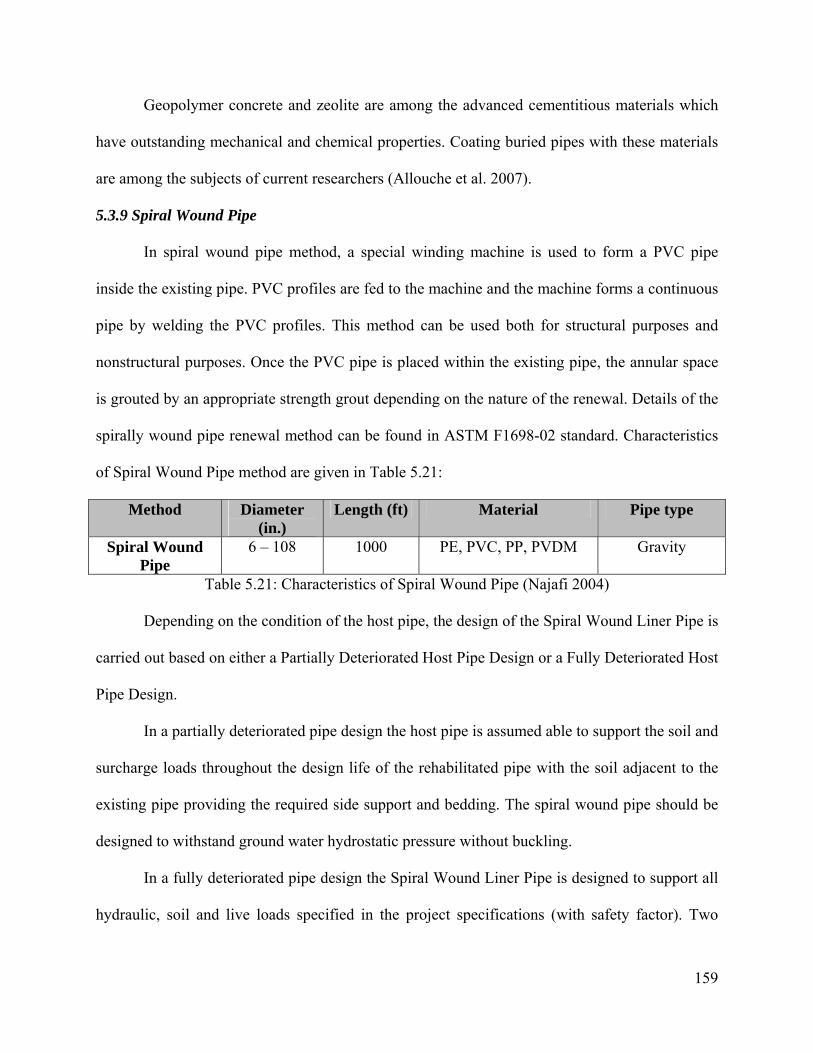
159
Geopolymer concrete and zeolite are among the advanced cementitious materials which
have outstanding mechanical and chemical properties. Coating buried pipes with these materials
are among the subjects of current researchers (Allouche et al. 2007).
5.3.9 Spiral Wound Pipe
In spiral wound pipe method, a special winding machine is used to form a PVC pipe
inside the existing pipe. PVC profiles are fed to the machine and the machine forms a continuous
pipe by welding the PVC profiles. This method can be used both for structural purposes and
nonstructural purposes. Once the PVC pipe is placed within the existing pipe, the annular space
is grouted by an appropriate strength grout depending on the nature of the renewal. Details of the
spirally wound pipe renewal method can be found in ASTM F1698-02 standard. Characteristics
of Spiral Wound Pipe method are given in Table 5.21:
Method Diameter (in.)
Length (ft) Material Pipe type
Spiral Wound Pipe
6 – 108 1000 PE, PVC, PP, PVDM Gravity
Table 5.21: Characteristics of Spiral Wound Pipe (Najafi 2004)
Depending on the condition of the host pipe, the design of the Spiral Wound Liner Pipe is
carried out based on either a Partially Deteriorated Host Pipe Design or a Fully Deteriorated Host
Pipe Design.
In a partially deteriorated pipe design the host pipe is assumed able to support the soil and
surcharge loads throughout the design life of the rehabilitated pipe with the soil adjacent to the
existing pipe providing the required side support and bedding. The spiral wound pipe should be
designed to withstand ground water hydrostatic pressure without buckling.
In a fully deteriorated pipe design the Spiral Wound Liner Pipe is designed to support all
hydraulic, soil and live loads specified in the project specifications (with safety factor). Two
160
distinctive design theories are used in the design of Fully Structural Spiral Wound Liner Pipe.
The first design theory looks at rigid plastic pipe design theory that utilizes the rigidity/stiffness
of the plastic profile combined with the supporting modulus of soil reaction to determine the
maximum external pressure allowed before the Spiral Wound Liner Pipe buckles. The second
design theory looks at the composite structure of Spiral Wound Liner Pipe, Grout, and any
Residual Structural Capability of Existing Host Pipe as one structural unit. The design of this
particular theory is either based on Reinforced Concrete Pipe Design or on WRc Type I Design.
It is noted that without accurate empirical test data which proves that composite action between
the grout and the host pipe occurs, most owners are reluctant to consider the residual structural
capability of the host pipe and therefore the resulting in an overdesigned Fully Structural Spiral
Wound Liner Pipe.
Each manufacturer of the Spiral Wound Lining System has undertaken testing to
determine the durability of their product for a 50 year design life. This includes the testing of
plastic’s short and long term tensile and bending stresses, the flexural modulus, etc to make sure
that the structural capability of the plastic is sustained over 50 years. Also, the design of the
water way thickness is such that the final spiral wound liner pipe will resist a minimum of 50
year abrasion from sand and other solid item that might be flowing through the pipe.
Some unevenness in wall roughness can be found in all commercially available pipes. In
spirally wound liner pipe, there is also irregularity of surface due to the spiral wound joint
connecting each successive profile wrap. However, documented testing by the spiral wound pipe
manufacturers has shown little difference in roughness coefficient exists between regular PVC
pipe and the spiral wound pipe.

161
Modifications for culvert applications using a Spiral Wound Lining System are minimal.
When rehabilitating corrugated metal pipe, additional bottom railing may be needed to guide the
wound liner pipe into the host pipe so that it does not get caught by the corrugations within the
host pipe.
Also, unlike sanitary sewer, the defects observed on storm sewer and culverts usually
occur on the bottom of the host pipe instead of the top. If the bottom of the storm sewer and/or
culvert is severely corroded, the bottom needs to be repaired prior to the installation of the spiral
wound liner pipe.
Spiral Wound Pipe Procedure:
The typical steps of spiral wound pipe renewal method are as follows:
• Placing the winding machine inside the pipe
• Feeding the PVC profiles into the machine
• Grouting the annular space
Placing the winding machine inside the pipe
This step involves positioning the special winding machine which continuously welds the
PVC strips to form the lining pipe. The winding machine can be stationary or traveling. If the
pipe to be rehabilitated is a sewer pipe, the machine can be lowered from an existing manhole.
Feeding the PVC profiles into the machine:
This step involves forming the actual liner by feeding the PVC profiles into the machine.
The profiles can be placed above the ground and fed through the machine.
Grouting the annular space:

162
The liner formed by the machine has a smaller cross sectional area compared to the host
pipe. The annular space left between the liner and the host pipe should be filled with an
appropriate strength grout.
Quality Assurance and Quality Control
• The plastic profile used in the Spiral Wound Lining System should be distinctly marked
on its surface at appropriate intervals with a code number identifying the manufacturer,
plant, date of manufacture and profile designation.
• When structural grout is required by the design, the grout should be sampled and tested as
designated by the owner. The properties that should be tested may include compression
strength test, bleed test, shrinkage test, flowability test, etc.
• After the completion of installation, the Spiral Wound Liner Pipe should be inspected
either by physical visual inspection or by closed circuit television.
• The spiral wound pipe shall be wound continuously over the entire length of the host pipe
and be free from defects such as foreign inclusions, holes, cuts, tears, and grout voids.
Any splices or grout holes should be repaired by manufacturer recommended material,
and no infiltration of ground water through the spiral wound liner pipe shall be observed.
All service connections should be accounted for and unobstructed.
• Any defect which will, or potentially could affect the structural integrity or performance
of the renewed conduit shall be repaired using means and method approved by the owner
before the final acceptance of the product.
Advantages of Spiral Wound Pipe:
The advantages of spiral wound pipe method are as follows (Najafi 2004):

163
• The lining pipe is formed by combining strips of PVC segments therefore large working
and storage space is not required.
• Mobilization costs are low.
• Bends with large radius can be negotiated with this method.
• Lining can be formed in various diameter sizes within the range of the winding machine.
• Overall costs are low-to-moderate.
Limitations of Spiral Wound Pipe:
Some of the limitations of the spiral wound pipe method are as follows (Najafi 2004):
• Skilled and trained personnel are needed to operate the winding equipment.
• Hydraulic capacity of the renewed pipe can be reduced significantly.
• Grouting is required to fill the annular space.
• The PVC strips have to be continuously welded, fused or mechanically joined together to
form a continuous joint.
Previous Research and Case Studies Related to Spiral Wound Pipe
Due to its advantages such as applicability to noncircular buried pipes and little working
space requirement, spiral wound pipe is becoming a popular method of renewal among the
world. In this section some of the case studies in which this renewal method was employed will
be covered:
A Japanese company developed a renewal method called Sewage Pipe Renewal (SPR) in
1986 in which a winding machine is used to form a rigid PVC pipe within existing buried pipes
(Morioka et al. 2003). Since then the company further improved this method to rehabilitate large
and noncircular pipes. The principles of SPR method is the same as the spiral wound pipe
method where a PVC strip is fed to the winding machine and once the liner is formed the annular
164
space is grouted. While renewing noncircular pipes “steel enhancements” are added to the PVC
profile in order to prevent the PVC from returning into a circular shape. The grouting procedure
can cause floating and deformation of the liner therefore profiles used in the renewal of large
pipes are selected as stiffer profiles and “support jacks” are installed with predefined intervals
along the pipeline. The company developed a method called the “New SPR Method” in which
the grouting process is performed simultaneously as the winding machine proceeds with the liner
formation. This method eliminates the use of support jacks and results in a faster renewal
procedure with improved flow characteristics compared to the conventional SPR method. The
fracture strength of the SPR method was tested on specimens of renewed standard box culverts
and box culverts with wall reduction of 25 mm with top reinforcing bars missing. According to
the results it was stated that the renewed pipe regained 2 to 3 times of the strength of the standard
culvert and regained an equal amount of strength in the case of renewal of a culvert with wall
reduction of 25 mm and missing top reinforcing steel bars. The compressive strength and flow
characteristics of renewed pipes by using new SPR method were also investigated. According to
the results the compression strength of the renewed was better than the original pipe and the flow
capacity was improved by 20%. Case studies in which a rectangular box culvert (with
dimensions 2750 mm by 1850 mm) was renewed by using the SPR method and a circular water
pipeline (with a diameter of 1800 mm) was renewed by using the new SPR method were
presented. In case of the box culvert the liner had dimensions of 2630 mm by 1730 mm and in
case of the circular pipe the liner had a diameter of 1750 mm. Both projects were completed
successfully and the pipes were back in service within a short amount of time.
SPR method was also used for the renewal of rectangular box culvert in Sapporo New
Chitose Airport, Sapparo, Japan (Nakamura et al. 2004). The box culvert had dimensions of
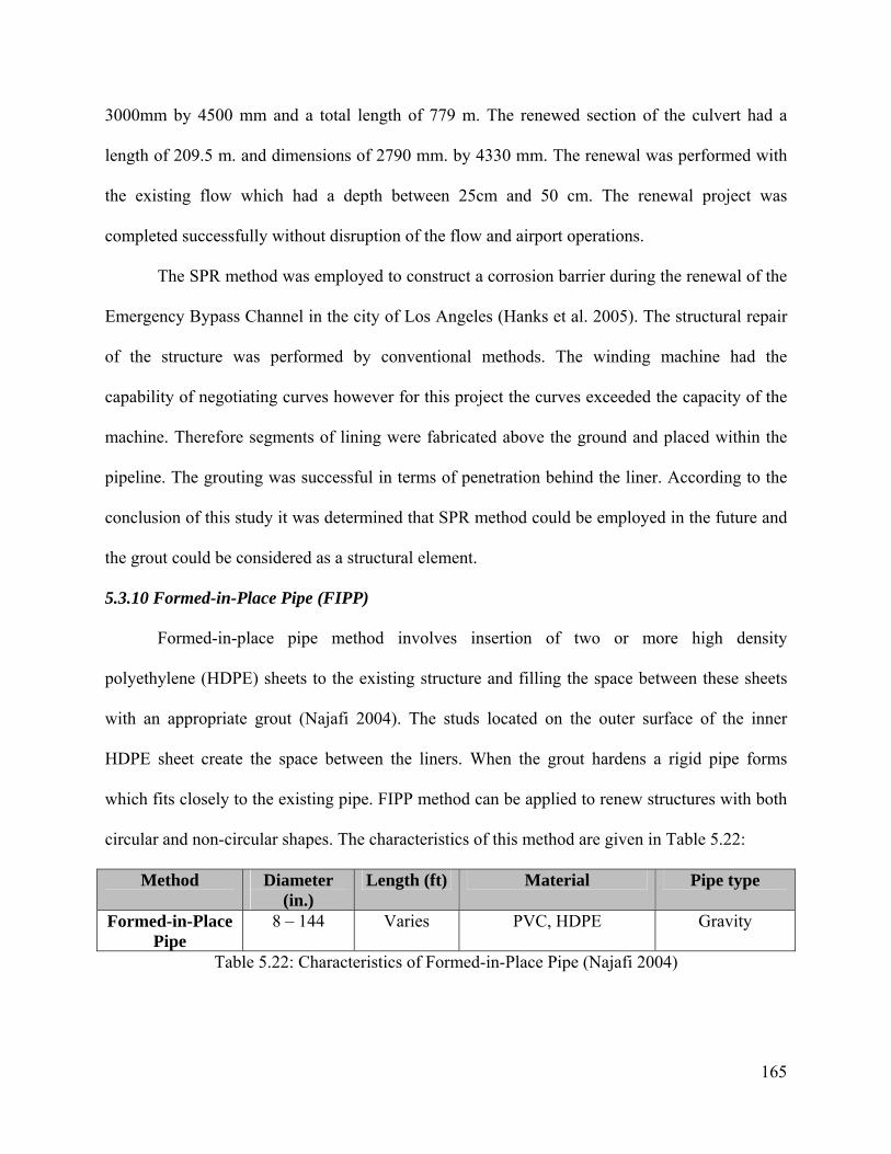
165
3000mm by 4500 mm and a total length of 779 m. The renewed section of the culvert had a
length of 209.5 m. and dimensions of 2790 mm. by 4330 mm. The renewal was performed with
the existing flow which had a depth between 25cm and 50 cm. The renewal project was
completed successfully without disruption of the flow and airport operations.
The SPR method was employed to construct a corrosion barrier during the renewal of the
Emergency Bypass Channel in the city of Los Angeles (Hanks et al. 2005). The structural repair
of the structure was performed by conventional methods. The winding machine had the
capability of negotiating curves however for this project the curves exceeded the capacity of the
machine. Therefore segments of lining were fabricated above the ground and placed within the
pipeline. The grouting was successful in terms of penetration behind the liner. According to the
conclusion of this study it was determined that SPR method could be employed in the future and
the grout could be considered as a structural element.
5.3.10 Formed-in-Place Pipe (FIPP)
Formed-in-place pipe method involves insertion of two or more high density
polyethylene (HDPE) sheets to the existing structure and filling the space between these sheets
with an appropriate grout (Najafi 2004). The studs located on the outer surface of the inner
HDPE sheet create the space between the liners. When the grout hardens a rigid pipe forms
which fits closely to the existing pipe. FIPP method can be applied to renew structures with both
circular and non-circular shapes. The characteristics of this method are given in Table 5.22:
Method Diameter (in.)
Length (ft) Material Pipe type
Formed-in-Place Pipe
8 – 144 Varies PVC, HDPE Gravity
Table 5.22: Characteristics of Formed-in-Place Pipe (Najafi 2004)
166
The portion of the HDPE panels exposed at the ends of the culvert must contain UV
protection such as carbon black. The translucent panels typically used for sanitary sewer
rehabilitation do not provide suitable UV protection for the exposed ends of culvert applications,
and if they are to be used, will require the application of additional UV protection measures at
the culvert ends.
Formed-in-Place Pipe Procedure:
The steps of formed-in-place pipe renewal method are as follows (Najafi 2004):
• Preparing the liners
• Installing the liners
• Grouting
Preparing the liners
This step involves fabrication of the HDPE liners specifically for the pipe to be renewed.
After fabrication these liners are transported to the job site in rolls and folded just before
insertion.
Installing the liners
This step involves inserting the folded liners into the pipe by pulling from the
downstream end. Once the liner is placed within the pipe it is returned to its original shape with
the application of pressure. The remaining liners are also placed within the pipe and pressurized
to obtain several lining pipes placed one after the other. The liners are forced to the host pipe
with the application of water pressure.
For culverts larger than 80in. in diameter, or of irregular geometry, the use of formworks,
instead of pressurization, is generally required for various constructability reasons. Where form
works prove to be advantageous, the technique can be used in any man-entry diameter pipe
167
(generally 42in. and larger). The form works must be structurally sufficient to withstand all
short-term loads including the grout. Although grouting in lifts has increased labor and
installation time disadvantages, there can be cost advantages from the reduced structural
requirements for the form works. Such considerations must be weighed on a case by case basis
(ASCE 2008).
The use of formworks avoids the use of high volumes of pressurization water, which is
frequently not readily accessible at remote culverts, or is prospectively environmentally
unacceptable. The use of form works has the added advantage of potentially reducing the
duration of by-pass pumping. On the other hand, forming the pipeline by pressurization has the
advantage of eliminating or at least reducing the need for man-entry and also significantly
reducing set-up labor costs and overall time of construction. Once again, such considerations
must be weighed on a case by case basis.
Grouting the annular space:
The last step involves grouting the space between the liners with an appropriate strength
grout. In order to avoid trapping air, the grout is generally introduced by gravity column and
allowed to flow from the lower end of the culvert upwards. The length which the grout can be
applied will be influenced by the slope of the culvert, the volume of grout that can be mixed and
injected during the allotted grout flow period, and the diameter of the pipeline. The water
pressure should be maintained while performing the grouting operation and should be released
after sufficient time (12 hours) is passed according to the manufacturer’s specifications.
Quality Assurance and Quality Control
The wall thickness and corrosion resistance of HDPE FIPP is unalterably established
during the pre-manufacturing of the HDPE pipeliner panels. However, the FIPP culvert
168
rehabilitation technique is still largely a field manufacturing process, which is inevitably subject
to variables which may affect the quality of constructed culvert pipeliners. Besides the QA/QC
procedures at the manufacturing facilities of the HDPE panels and the grout, QA/QC at the
construction site is essential to control the influence of field variables and to provide the
customer with the best quality product as constructed.
The following inherent technology advantages facilitate the QA/QC of FIPP pipeliners:
• The minimum thickness of the pipeliner is the height of the embedded anchors and is
unalterable by field conditions or by construction crew decisions.
• The grout is injected into the sealed annulus between the layers of the pipeliner using a
gravity column, instead of pumping; this tends to preclude the creation of grout voids
inside the pipeliner.
• The required volume of grout necessary to achieve the structural wall thickness
requirements is established and controlled by the fixed, sealed annulus between the layers
of the pipeliner.
• The application of the preliner prevents the grout from escaping, washing away, or losing
strength due to dilution by ground water.
• The weld quality and the water-tightness of the HDPE FIPP are confirmed during the
installation process.
Since critical structural design properties of a HDPE FIPP are established during field
manufacturing, additional field quality tests are essential before and during the grouting process
to ensure that design values are being achieved under varying field conditions. With HDPE FIPP,
design compliance is monitorable and confirmable during installation. Required field quality

169
tests of the structural grout include: viscosity, weight, water-cement ratio, temperature, and
material expansion (ASCE 2008).
Since temperature, humidity, and other field conditions routinely vary as the installation
progresses, the field crews are required to make adjustments to maintain the water-cement ratio
of the grout in order to maintain specification compliance. By maintaining tolerances throughout
the installation process, the specification compliance and consistency of the HDPE FIPP can be
confirmed down the full length of the installed pipeliner. Conformance of these material property
requirements during field manufacturing should also ensure that the post-construction strength
tests of grout beam samples will also comply with the specification requirements and be reliably
representative of the full length of the as-constructed HDPE FIPP.
Voids are not known to form with such low viscosity grout (prior to curing it flows like
milk) which is injected by gravity column from the low end to the high end of the culvert. With
the translucent HDPE panels, an internal visual inspection, even by CCTV, can confirm the lack
of voids in the grout. For man-entry sizes, a “tapping test” can confirm the lack of voids behind
an opaque HDPE panel.
Advantages of FIPP
The advantages of FIPP method are as follows (Najafi 2004):
• FIPP method can be applied to renew any shape drainage structure up to 12 ft in
diameter.
• This method offers both structural solutions and corrosion control.
• Culverts can be renewed with FIPP method.
• This method can be applied in long drive-lengths.
• Hydraulic capacity can be improved due to using a smoother lining material.

170
• The liner installed is resistant to abrasion and chemicals.
Limitations of FIPP
The limitations of FIPP method are as follows (Najafi 2004):
• Cross sectional area can be reduced significantly.
• Construction of access shafts may be required.
• Grouting must be used to fill the annular space between lining sheets.
Previous Case Study Related to FIPP
Formed in Place Pipe Method was used to renew 520 meter long brick sewer pipeline in
Bielefeld, Germany (Kirste 2007). The commercial name for the method used is Trolining. In
this specific project the preliner was not used, therefore the outer wall of the lining pipe was
actually the host pipe itself. The grouting procedure in this renewal project helped repair the joint
problems of the host pipe. The project started by diverting the existing flow and preparing the
old sewer line for the insertion of liners. The liners were inserted through the manholes located
above the sewer. The liner ends were sealed and egg-shaped packers were installed. Water was
pumped to obtain the required hydrostatic pressure. The annular spaces between the liners and
the host pipe and the liner were grouted by using special grouts. The outer annular space was
grouted first and then the inner annular space was grouted afterwards. After curing the pressure
was released. Finally the service connections were established.
5.3.11 In-Line Replacement
In-line replacement of buried pipes involves trenchless procedures in which the
deteriorated pipe is replaced with a new pipe having the same or a larger diameter. In-line
replacement can be performed either by fracturing and splitting the existing pipe and inserting a

171
new pipe, namely by pipe bursting, or by destroying and removing the existing pipe, namely by
pipe removal (Najafi 2004).
Pipe Bursting procedure:
The procedure for pipe bursting in general includes inserting a cone to the existing pipe
which is connected to a winch at the downstream pit and pulling this cone to fracture the existing
pipe. While the cone advances through the deteriorated pipe a new pipe, which is connected to
the cone, replaces the fractured parts simultaneously. Depending on the type of force applied to
the existing pipe the pipe bursting can be divided into static pipe bursting, hydraulic pipe
bursting or pneumatic pipe bursting. If the pipe material is not brittle a different type of cone,
which first cuts the pipe and then splits the pipe, should be used.
As a general rule, the pipe bursting project is subdivided into sections or lengths so that
the specific bursting equipment can perform bursting based on the geometry and layout of the
total length of culvert being replaced. The length of the culvert that can be replaced in a section
is dependent on the type of pipe being burst, degree of upsize, soil conditions, geometry of the
original installation, and the type of bursting equipment and method used. In addition, the new
pipe, whether it is continuous or sectional, will dictate the type of equipment required and the pit
setup (Lueke & Ariaratnam 2001).
The maximum size of a pipe which can be renewed pipe bursting is given as 48 in.
however larger sized pipes were renewed by using this method. Larger energy need and ground
disturbance are the factors which limit the maximum size of the pipe bursting method (Najafi
2004). The characteristics of pipe bursting are given in table 5.23.
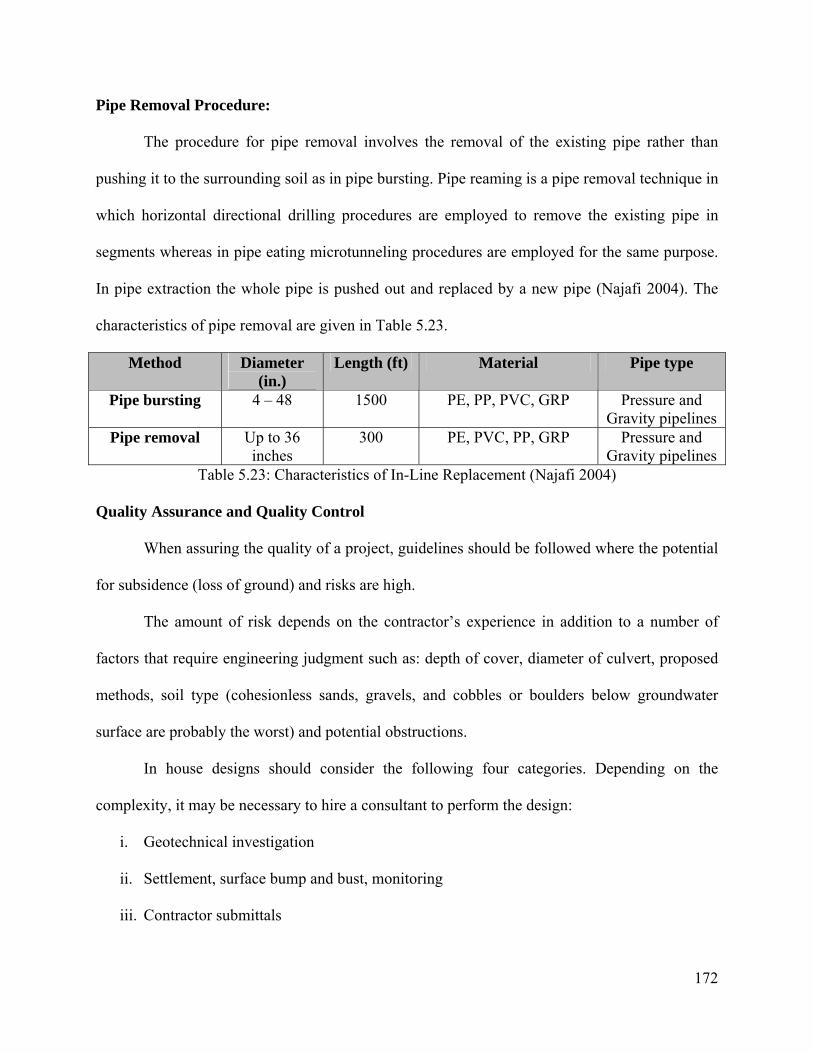
172
Pipe Removal Procedure:
The procedure for pipe removal involves the removal of the existing pipe rather than
pushing it to the surrounding soil as in pipe bursting. Pipe reaming is a pipe removal technique in
which horizontal directional drilling procedures are employed to remove the existing pipe in
segments whereas in pipe eating microtunneling procedures are employed for the same purpose.
In pipe extraction the whole pipe is pushed out and replaced by a new pipe (Najafi 2004). The
characteristics of pipe removal are given in Table 5.23.
Method Diameter (in.)
Length (ft) Material Pipe type
Pipe bursting 4 – 48 1500 PE, PP, PVC, GRP Pressure and Gravity pipelines
Pipe removal Up to 36 inches
300 PE, PVC, PP, GRP Pressure and Gravity pipelines
Table 5.23: Characteristics of In-Line Replacement (Najafi 2004)
Quality Assurance and Quality Control
When assuring the quality of a project, guidelines should be followed where the potential
for subsidence (loss of ground) and risks are high.
The amount of risk depends on the contractor’s experience in addition to a number of
factors that require engineering judgment such as: depth of cover, diameter of culvert, proposed
methods, soil type (cohesionless sands, gravels, and cobbles or boulders below groundwater
surface are probably the worst) and potential obstructions.
In house designs should consider the following four categories. Depending on the
complexity, it may be necessary to hire a consultant to perform the design:
i. Geotechnical investigation
ii. Settlement, surface bump and bust, monitoring
iii. Contractor submittals
173
iv. Contract inspection
Items 2 and 3 should be addressed in the plans and specifications and should be based on the
results of item 1.
Advantages of In-Line Replacement Methods:
The in-line replacement methods offer the following advantages (Najafi 2004):
• In-Line replacement methods can be used to renew a wide range of pipe types.
• Diameter of the pipe can be increased.
• The renewed pipe has the same alignment with the existing pipe
• The existing pipe does not have to be disposed if pipe bursting is employed.
Limitations of the In-Line Replacement Methods:
Some of the limitations of the in-line replacement methods are as follows (Najafi 2004):
• Shafts may be required for insertion and reception.
• Construction equipment over the ground needs working space.
• Lateral service connections should be established by open cut excavation.
• The renewal should be performed while the flow is diverted.
• Nearby utilities and structures may be damaged if excessive ground movements and
vibrations are present in the job site.
Previous Research and Case Studies Related to In-Line Replacement
There have been several research studies related to the installation and performance of in-
line replacement techniques. In this section some of these important studies will be discussed:
Pipe bursting was selected as the proper replacement method to renew a 450 mm
diameter clay tile combined sewer in the City of Edmonton, Alberta, Canada (Kwan and Chua
2005). The existing pipe was located at a depth of 6.6 meters to 7.4 meters. It was originally built
174
in 1914 and as a result of CCTV inspection it was determined that the pipe could collapse
immediately. After conducting a cost estimate for alternative renewal options it was decided to
perform pipe bursting for 85 meters of the deteriorated pipe, constructing a new manhole and
relining the remaining 105 meters. The contractor suggested performing pipe bursting for the
whole length of the pipe and it was accepted. However during the execution of the project the
bursting head was broken half way through the renewal process. The portion of the pipe which
was not renewed by pipe bursting was found out to be in good condition therefore the renewal
process was finished and a new manhole was built. The reason for the breakage of the bursting
head was due to the pipe bedding change into concrete encasement.
Pipe bursting was applied in the renewal of a 18-inch diameter 310 feet long clay sanitary
sewer pipe on the campus of Michigan State University (Lee et al. 2007). 4 different open-cut
replacement methods were compared with the pipe bursting. The open-cut options were, simple
sloping, simple sloping with benches, combination of sloping and shielding, and shoring or
shielding. The first two options were not included in the cost comparison due to the extensive
excavation needed to perform simple sloping. In option 3 (combination of sloping and shielding)
the amount of shielding was less than the one in option 4 (shoring or shielding) however
replacing the pavement and restoring the backfill was more costly. The cost estimates for option
3 and option 4 were found out to be $100,974 and $137,298 respectively. The major portion of
the open cut replacement cost estimate was due to the excavation, pipe installation and
backfilling operations. The cost estimate for the pipe bursting process in which the new pipe was
the same size with the original pipe was found out to be $71,965. The actual cost of the renewal
by pipe bursting was given as $52,000 of which $30,000 was due to the pipe bursting process
itself. According to the findings of the study pipe bursting can be cost effective and faster
175
compared to open cut procedures. If the length of the pipe to be renewed increases pipe bursting
becomes more efficient since the excavation and backfilling costs increase with a higher order
compared to the linear nature of pipe bursting operation.
Lueke and Ariaratnam cite three case studies in which pipe bursting was employed in
order to renew buried pipelines (2001). In the first case study a 450 mm diameter 300 meter long
corrugated metal pipe was renewed in the city of Renton, WA. In order to break and split the
corrugated metal pipe cutting fins were placed on the pulling rod, however these fins failed to cut
the existing pipe after some time and made the bursting operations further complicated.
Therefore another method in which a 1 meter long pipe with cutting wheels installed on it was
used to burst the CMP. This method proved to be successful and the pipe was renewed by pipe
bursting with the help of cutting wheels. In the second case study, pipe bursting method was used
to renew a section of a 300 mm diameter clay sewer pipe in Calgary, Alberta. The difficulty of
this project was due to the highly congested location of one of manholes which made the
construction of an access pit impossible. To overcome this difficulty a smaller bursting machine
which pulled the back side of a new segment of the new pipe was used simultaneously with a
large bursting machine which was connected to the bursting head. A polymer lubricant was used
to overcome difficulties due to the soil type. The contractor successfully renewed the clay pipe
with a rigid polyethylene pipe having a 12.5 mm wall thickness. In the third case study, the
surface heave problem due to the vertical misalignment of the new pipe during pipe bursting of a
56 meter long 600 mm diameter reinforced concrete pipe in the city of Phoenix is described. The
vertical misalignment was due to the failure of bursting head to cut the invert of the existing
pipe. In order to overcome this problem the bursting head was elongated on both sides which
helped the bursting head to remain within the existing pipe. The invert of the existing pipe was
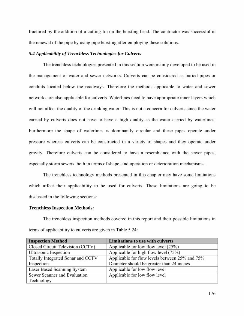
176
fractured by the addition of a cutting fin on the bursting head. The contractor was successful in
the renewal of the pipe by using pipe bursting after employing these solutions.
5.4 Applicability of Trenchless Technologies for Culverts
The trenchless technologies presented in this section were mainly developed to be used in
the management of water and sewer networks. Culverts can be considered as buried pipes or
conduits located below the roadways. Therefore the methods applicable to water and sewer
networks are also applicable for culverts. Waterlines need to have appropriate inner layers which
will not affect the quality of the drinking water. This is not a concern for culverts since the water
carried by culverts does not have to have a high quality as the water carried by waterlines.
Furthermore the shape of waterlines is dominantly circular and these pipes operate under
pressure whereas culverts can be constructed in a variety of shapes and they operate under
gravity. Therefore culverts can be considered to have a resemblance with the sewer pipes,
especially storm sewers, both in terms of shape, and operation or deterioration mechanisms.
The trenchless technology methods presented in this chapter may have some limitations
which affect their applicability to be used for culverts. These limitations are going to be
discussed in the following sections:
Trenchless Inspection Methods:
The trenchless inspection methods covered in this report and their possible limitations in
terms of applicability to culverts are given in Table 5.24:
Inspection Method Limitations to use with culverts Closed Circuit Television (CCTV) Applicable for low flow level (25%) Ultrasonic Inspection Applicable for high flow level (75%) Totally Integrated Sonar and CCTV Inspection
Applicable for flow levels between 25% and 75%. Diameter should be greater than 24 inches.
Laser Based Scanning System Applicable for low flow level Sewer Scanner and Evaluation Technology
Applicable for low flow level
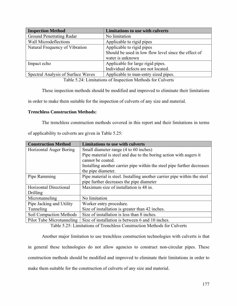
177
Inspection Method Limitations to use with culverts Ground Penetrating Radar No limitation Wall Microdeflections Applicable to rigid pipes Natural Frequency of Vibration Applicable to rigid pipes
Should be used in low flow level since the effect of water is unknown
Impact echo Applicable for large rigid pipes. Individual defects are not located.
Spectral Analysis of Surface Waves Applicable to man-entry sized pipes. Table 5.24: Limitations of Inspection Methods for Culverts
These inspection methods should be modified and improved to eliminate their limitations
in order to make them suitable for the inspection of culverts of any size and material.
Trenchless Construction Methods:
The trenchless construction methods covered in this report and their limitations in terms
of applicability to culverts are given in Table 5.25:
Construction Method Limitations to use with culverts Horizontal Auger Boring Small diameter range (4 to 60 inches)
Pipe material is steel and due to the boring action with augers it cannot be coated. Installing another carrier pipe within the steel pipe further decreases the pipe diameter.
Pipe Ramming Pipe material is steel. Installing another carrier pipe within the steel pipe further decreases the pipe diameter
Horizontal Directional Drilling
Maximum size of installation is 48 in.
Microtunneling No limitation Pipe Jacking and Utility Tunneling
Worker entry procedure. Size of installation is greater than 42 inches.
Soil Compaction Methods Size of installation is less than 8 inches. Pilot Tube Microtunneling Size of installation is between 6 and 10 inches.
Table 5.25: Limitations of Trenchless Construction Methods for Culverts
Another major limitation to use trenchless construction technologies with culverts is that
in general these technologies do not allow agencies to construct non-circular pipes. These
construction methods should be modified and improved to eliminate their limitations in order to
make them suitable for the construction of culverts of any size and material.
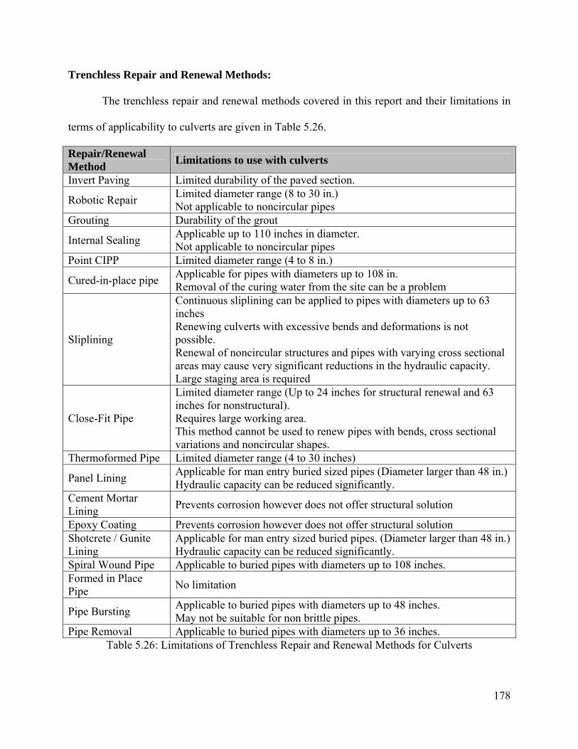
178
Trenchless Repair and Renewal Methods:
The trenchless repair and renewal methods covered in this report and their limitations in
terms of applicability to culverts are given in Table 5.26.
Repair/Renewal Method Limitations to use with culverts
Invert Paving Limited durability of the paved section.
Robotic Repair Limited diameter range (8 to 30 in.) Not applicable to noncircular pipes
Grouting Durability of the grout
Internal Sealing Applicable up to 110 inches in diameter. Not applicable to noncircular pipes
Point CIPP Limited diameter range (4 to 8 in.)
Cured-in-place pipe Applicable for pipes with diameters up to 108 in. Removal of the curing water from the site can be a problem
Sliplining
Continuous sliplining can be applied to pipes with diameters up to 63 inches Renewing culverts with excessive bends and deformations is not possible. Renewal of noncircular structures and pipes with varying cross sectional areas may cause very significant reductions in the hydraulic capacity. Large staging area is required
Close-Fit Pipe
Limited diameter range (Up to 24 inches for structural renewal and 63 inches for nonstructural). Requires large working area. This method cannot be used to renew pipes with bends, cross sectional variations and noncircular shapes.
Thermoformed Pipe Limited diameter range (4 to 30 inches)
Panel Lining Applicable for man entry buried sized pipes (Diameter larger than 48 in.) Hydraulic capacity can be reduced significantly.
Cement Mortar Lining Prevents corrosion however does not offer structural solution
Epoxy Coating Prevents corrosion however does not offer structural solution Shotcrete / Gunite Lining
Applicable for man entry sized buried pipes. (Diameter larger than 48 in.) Hydraulic capacity can be reduced significantly.
Spiral Wound Pipe Applicable to buried pipes with diameters up to 108 inches. Formed in Place Pipe No limitation
Pipe Bursting Applicable to buried pipes with diameters up to 48 inches. May not be suitable for non brittle pipes.
Pipe Removal Applicable to buried pipes with diameters up to 36 inches. Table 5.26: Limitations of Trenchless Repair and Renewal Methods for Culverts

179
The repair and renewal methods should be modified and improved to eliminate their
limitations in order to make them suitable for the renewal of culverts of any size and material.

180
6. Asset Management of Culverts
The majority of transportation infrastructure elements of the United States have reached
to the end of their design lives. The aging infrastructure is forcing the transportation agency
officials to make correct and fast decisions regarding the preservation of these assets. The
necessity and importance of a systematic way of gathering information and decision making
procedures is becoming more obvious as transportation assets are either failing or causing
agencies to perform costly emergency repairs after failures. A comprehensive asset management
strategy offers the solution to this complex problem by establishing the rules and protocols for
information gathering and decision-making procedures.
The Governmental Accounting and Standards Board – Rule 34 (GASB-34) brought new
rules for the state departments of transportation (DOTs) which required them to determine and
document the conditions of their assets by implementing asset management procedures.
Transportation elements such as pavements and bridges were among the important elements for
transportation agencies however culverts and buried pipes were often neglected. Due to aging
and accelerated deterioration rates, and high costs of emergency replacements or failures these
elements are gaining more importance and agencies are searching for ways of implementing a
comprehensive asset management strategy.
Federal Highway Administration (FHWA) defines asset management as “a systematic
process of maintaining, upgrading, and operating physical assets cost-effectively”. It is also
added that “it combines engineering principles with sound business practices and economic
theory, and it provides tools to facilitate a more organized, logical approach to decision-making.
Thus, asset management provides a framework for handling both short- and long-range
planning.” (FHWA, 1999)
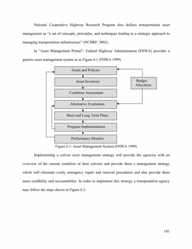
181
National Cooperative Highway Research Program also defines transportation asset
management as “a set of concepts, principles, and techniques leading to a strategic approach to
managing transportation infrastructure” (NCHRP, 2002).
In “Asset Management Primer”, Federal Highway Administration (FHWA) provides a
generic asset management system as in Figure 6.1 (FHWA 1999)
Figure 6.1: Asset Management System (FHWA 1999)
Implementing a culvert asset management strategy will provide the agencies with an
overview of the current condition of their culverts and provide them a management strategy
which will eliminate costly emergency repair and renewal procedures and also provide them
more credibility and accountability. In order to implement this strategy a transportation agency
may follow the steps shown in Figure 6.2:
Budget Allocation
Program Implementation
Goals and Policies
Performance Monitor
Asset Inventory
Condition Assessment
Short and Long Term Plans
Alternative Evaluation

182
Figure 6.2: Steps of Implementing a Culvert Asset Management Program
Ohio Department of Transportation (ODOT) established their inventory and inspection
procedures and published the “Ohio Department of Transportation Culvert Management
Manual” in 2003. These procedures were covered in detail in a previous MRUTC research
project entitled as “An Asset Management Approach for Drainage Infrastructure and Culverts”
conducted by the investigators. Apart from the inspection and inventory procedures a decision
support platform was also generated.
In this chapter the steps of a culvert asset management program and the potential use of
trenchless technologies to improve this asset management strategy are going to be covered.
6.1 Establishing Inventory Protocols and Database
Establishing an inventory protocol and generating a computerized inventory database is
the first step of implementing a culvert asset management program. The inventory database

183
provides valuable information such as the size, location, material, etc. of each culvert the agency
is responsible of managing.
Ohio Department of Transportation (ODOT) uses the form CR-87 (see appendix 3) to
record the inventory information for each culvert. This form is used to add a newly constructed
culvert to the database or to remove a retiring culvert from the database or to modify the
information on the database whenever changes have been made to the existing culvert.
The following items are addressed while filling the CR-87 form:
Culvert File Number
Item 1: Entry Class
Location and Route Information:
Item 2: District
Item 3: County
Item 4: Route
Item 5: Straight Line Mileage
Item 6: Latitude
Item 7: Longitude
Item 8: Road ID
Item 9: Maintenance Responsibility
Item 10: Feature Inspection
Culvert
Item 11: Year Built
Item 12: Number of Cells
Item 13: Shape
Item 14: Material
Item 15: Span
Item 16: Rise
Item 17: Length
Item 18: Gage / Wall Thickness
Item 19: Gage / Wall Thickness
Item 20: Type of Protection
Item 21: Slope of Pipe (%)
Item 22: Skew
Item 23: Inlet end treatment
Item 24: Outlet end treatment

184
Item 25: Maximum height of cover
Item 26: Modification Type
Item 27: Year Modified
Item 28: Modification Material
Item 29: Modification Size
Extension Inlet
Item 30: Year extended
Item 31: Shape
Item 32: Material
Item 33: Span
Item 34: Rise
Item 35: Gage / Wall Thickness
Item 36: Extension length
Extension Outlet
Item 37: Year extended
Item 38: Shape
Item 39: Material
Item 40: Span
Item 41: Rise
Item 42: Gage / Wall Thickness
Item 43: Extension length
Hydrology / Hydraulics
Item 44: Drainage area
Item 45: Design discharge
Item 46: Abrasive conditions
Item 47: pH
Item 48: Channel protection (inlet)
Item 49: Channel protection (outlet)
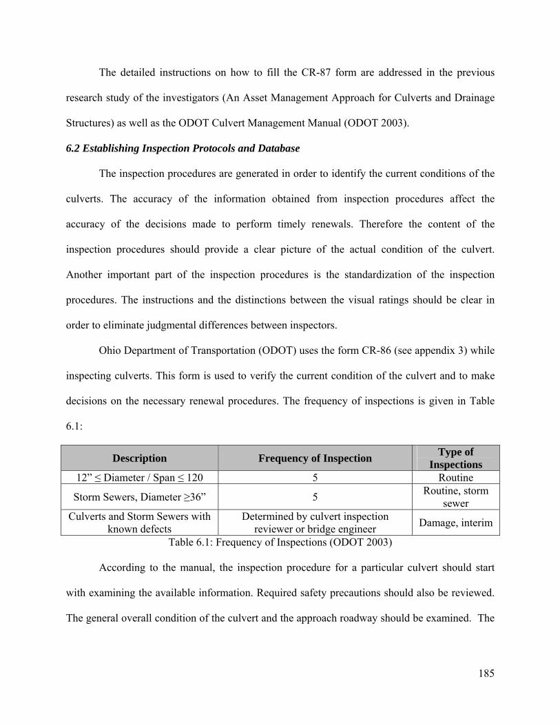
185
The detailed instructions on how to fill the CR-87 form are addressed in the previous
research study of the investigators (An Asset Management Approach for Culverts and Drainage
Structures) as well as the ODOT Culvert Management Manual (ODOT 2003).
6.2 Establishing Inspection Protocols and Database
The inspection procedures are generated in order to identify the current conditions of the
culverts. The accuracy of the information obtained from inspection procedures affect the
accuracy of the decisions made to perform timely renewals. Therefore the content of the
inspection procedures should provide a clear picture of the actual condition of the culvert.
Another important part of the inspection procedures is the standardization of the inspection
procedures. The instructions and the distinctions between the visual ratings should be clear in
order to eliminate judgmental differences between inspectors.
Ohio Department of Transportation (ODOT) uses the form CR-86 (see appendix 3) while
inspecting culverts. This form is used to verify the current condition of the culvert and to make
decisions on the necessary renewal procedures. The frequency of inspections is given in Table
6.1:
Description Frequency of Inspection Type of Inspections
12” ≤ Diameter / Span ≤ 120 5 Routine
Storm Sewers, Diameter ≥36” 5 Routine, storm sewer
Culverts and Storm Sewers with known defects
Determined by culvert inspection reviewer or bridge engineer Damage, interim
Table 6.1: Frequency of Inspections (ODOT 2003)
According to the manual, the inspection procedure for a particular culvert should start
with examining the available information. Required safety precautions should also be reviewed.
The general overall condition of the culvert and the approach roadway should be examined. The

186
embankment, end treatment structures and the culvert barrel should be examined from the outlet
and the procedure should be repeated for the inlet.
The manual defines the entry procedure while inspecting culverts according to the
following flow chart (Figure 6.3):
Figure 6.3 Culvert Entry Class (ODOT 2003)
Trenchless inspection methods such as closed circuit television (CCTV), ultrasound
inspection or totally integrated sonar and CCTV can be implemented to the flow chart to replace
the procedures for Class D and Class C entry type culverts. CCTV method is useful for
inspecting pipes with 25% flow. The ultrasound inspection is useful for inspecting pipes with
more than 75% flow. To inspect any pipe which has a flow level between 25% and 65%
integrated ultrasound and CCTV methods can be used.
Some of the items of the inspection form (CR-86) provided in the ODOT Culvert
Management Manual are as follows:
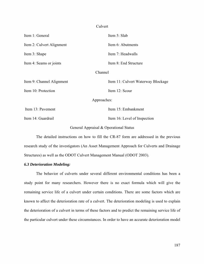
187
Culvert
Item 1: General
Item 2: Culvert Alignment
Item 3: Shape
Item 4: Seams or joints
Item 5: Slab
Item 6: Abutments
Item 7: Headwalls
Item 8: End Structure
Channel
Item 9: Channel Alignment
Item 10: Protection
Item 11: Culvert Waterway Blockage
Item 12: Scour
Approaches:
Item 13: Pavement
Item 14: Guardrail
Item 15: Embankment
Item 16: Level of Inspection
General Appraisal & Operational Status
The detailed instructions on how to fill the CR-87 form are addressed in the previous
research study of the investigators (An Asset Management Approach for Culverts and Drainage
Structures) as well as the ODOT Culvert Management Manual (ODOT 2003).
6.3 Deterioration Modeling:
The behavior of culverts under several different environmental conditions has been a
study point for many researchers. However there is no exact formula which will give the
remaining service life of a culvert under certain conditions. There are some factors which are
known to affect the deterioration rate of a culvert. The deterioration modeling is used to explain
the deterioration of a culvert in terms of these factors and to predict the remaining service life of
the particular culvert under these circumstances. In order to have an accurate deterioration model
188
inspection results gathered over time need to be examined carefully and a statistical model which
will fit closely to the actual deterioration characteristics should be generated.
6.4 Prioritizing the culverts:
According to the results of the deterioration modeling the remaining service life and rate
of deterioration should be used to identify the culverts which need immediate attention in terms
of renewal. The risk of failure and the cost of failure for each culvert should be determined and
this information should be used in order to categorize the culverts in terms of risk levels. The
highest risk category should involve culverts which need immediate attention in terms of renewal
(repair, rehabilitation or replacement).
Prioritizing can be accomplished by using one of the following methods (Hudson et al.
1997):
• Ranking projects based on subjective judgment
• Ranking by using parameters such as level of service and condition
• Ranking by using parameters regarding the economic analysis
• Optimization on a year-by-year basis
• Near optimization by incorporating a marginal cost-effectiveness approach
• Comprehensive optimization taking into account “which, what and when”
6.5 Establishing a decision support system
The objective of implementing a culvert asset management strategy is to make accurate
and justified decisions regarding the repair and renewal (rehabilitation and replacement) of the
culverts. In order to accomplish this objective a systematic way of decision making procedures
has to be generated. The inventory, inspection, deterioration modeling and prioritization
procedures enable the decision maker to identify which culverts need immediate response and
189
which culverts are still within the safe operating conditions. Next step of the culvert asset
management involves generating a decision support system which aids the decision maker in
terms of providing available options for each risk category of the culvert database.
Repair procedures are used to solve the problems related to a portion of the culvert
therefore they do not improve the condition of the culvert as a whole. Some of the common
repair procedures involve invert paving, patching, grouting, internal sealing and point CIPP.
Renewal procedures can be divided into rehabilitation and replacement. Rehabilitation of
culverts involves procedures which improve the overall condition of the culvert without
removing the existing pipe. Therefore rehabilitation methods involve lining methods which cover
the whole length and circumference of the culvert. Replacement of a culvert involves either
removing or destroying the existing culvert and placing a new one to the same alignment. Open
cut method is the most commonly used method of culvert replacement. However trenchless
replacement techniques such as pipe bursting and pipe removal are becoming more popular
especially to replace buried pipes located under busy roadways and under high fill.
The trenchless repair and renewal methods were covered in detail in chapter 5. Some of
the basic characteristics of these methods are summarized in table 6.2. (The comparative cost
column is generated by using the information provided on “Trenchless Technology” (Najafi
2004). The actual values may differ depending on the region. This information is provided as a
general reference.) Table 6.2 can be used to identify potential repair and renewal methods which
suit the circumstances at hand. This table is generated to develop a database of trenchless repair
and renewal options. A detailed decision support system which identifies the optimum repair or
renewal procedure given the condition of the culvert depending on the Ohio Culvert
Management Manual inspection procedures is provided in the next chapter.
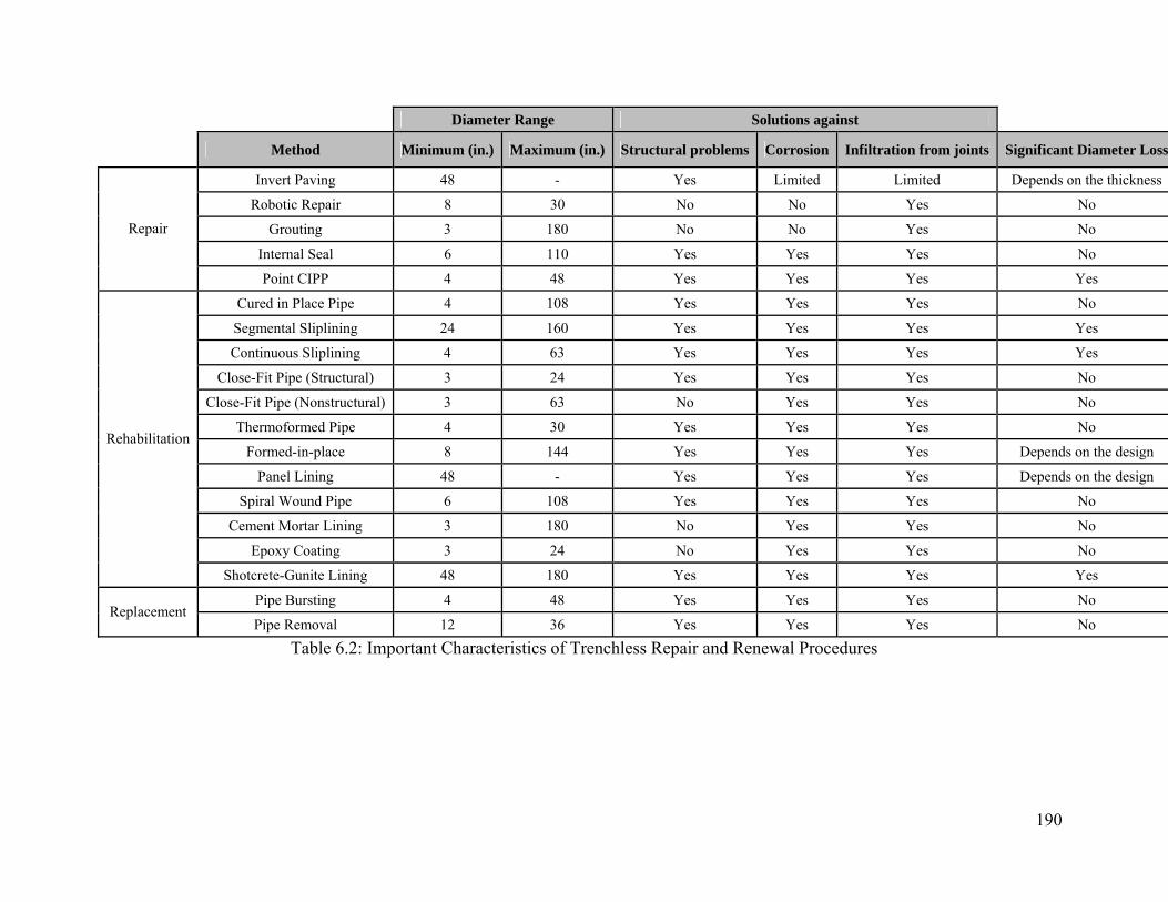
190
Diameter Range Solutions against
Method Minimum (in.) Maximum (in.) Structural problems Corrosion Infiltration from joints Significant Diameter Loss
Invert Paving 48 - Yes Limited Limited Depends on the thickness
Robotic Repair 8 30 No No Yes No
Grouting 3 180 No No Yes No
Internal Seal 6 110 Yes Yes Yes No
Repair
Point CIPP 4 48 Yes Yes Yes Yes
Cured in Place Pipe 4 108 Yes Yes Yes No
Segmental Sliplining 24 160 Yes Yes Yes Yes
Continuous Sliplining 4 63 Yes Yes Yes Yes
Close-Fit Pipe (Structural) 3 24 Yes Yes Yes No
Close-Fit Pipe (Nonstructural) 3 63 No Yes Yes No
Thermoformed Pipe 4 30 Yes Yes Yes No
Formed-in-place 8 144 Yes Yes Yes Depends on the design
Panel Lining 48 - Yes Yes Yes Depends on the design
Spiral Wound Pipe 6 108 Yes Yes Yes No
Cement Mortar Lining 3 180 No Yes Yes No
Epoxy Coating 3 24 No Yes Yes No
Rehabilitation
Shotcrete-Gunite Lining 48 180 Yes Yes Yes Yes
Pipe Bursting 4 48 Yes Yes Yes No Replacement
Pipe Removal 12 36 Yes Yes Yes No
Table 6.2: Important Characteristics of Trenchless Repair and Renewal Procedures

191
6.6 Improvement of the asset management strategies:
This step involves modifying the previous steps of the asset management strategy,
inventory procedures, inspection procedures, deterioration modeling, prioritization, and decision
support system, according to the technological developments and experiences with some of the
previous decisions.
The technological developments offer new trenchless renewal methods and at the same
time improve the existing methods. These improvements should be a part of upgrading the
available renewal options list.
Once a culvert is repaired or renewed (rehabilitated or replaced) the information
regarding this culvert in the culvert inventory database should be updated. Items 26 through 29
of the Culvert Inventory Form (CR-87) of ODOT Culvert Management Manual covers important
information regarding the modifications made to the existing culvert.
Inspection and maintenance procedures of a renewed culvert do not defer from these of
an existing culvert. However if the culvert is repaired due to a defect the inspection frequency for
this culvert should be shorter. Since repair procedures do not cover the whole length of the
culvert but only a portion the same types of problems can be experienced in the rest of the
culvert. Rehabilitated and replaced culverts typically have the same design life with a newly
constructed culvert. Therefore the inspection requirements of rehabilitated and replaced do not
differ from the newly constructed culverts. It is of utmost importance to inspect the renewed
culvert during the renewal procedure and as soon as the renewal is completed. The procedures
have to be performed according to the particular standards and design requirements. Samples
from the field have to be taken and tested. For rehabilitation projects where a culvert is lined and
a new pipe is formed within the existing pipe careful inspection of the final product is extremely

192
important. The renewed culvert should be inspected for any defects such as bulging, fins,
deformations and if any problems are detected they should be corrected immediately.
193
7. Establishing a Database and a Decision Support System
Usage of trenchless technologies for renewal of buried pipes has offered a solution to
manage these assets located under high fills and/or congested areas. Especially water and waste
water agencies have been using these techniques whenever the site conditions dictated
performing a structural or non-structural renewal of the system without disturbing the pavement,
moving traffic and other utility lines located underground such as gas and communication lines.
Culverts can be categorized as both buried pipes in small diameters with no access and worker
entry and pipes in larger diameters with possibility of manual inspection and renewal. Trenchless
technologies offer the same advantages of cost savings, safety, and non-disturbance of the
surrounding facilities for culverts. However many DOTs have started using these technologies
without clear standard methodology. Despite the increasing popularity of these methods there is
still a lack of guidance and DOT-centered decision support systems on how to make the correct
decisions regarding the selection of these methods. The aim of this section is to propose a
methodology to develop a database of trenchless technologies used while managing culverts and
a decision support system which will help the agencies to select the optimum trenchless
technology given the condition of the culvert.
7.1 Database of Trenchless Technology Methods
The purpose of establishing a database of trenchless technology methods is to record all
the information associated with the trenchless technology methods used to renew culverts such
as cost, problems faced during pre-construction, construction and post-construction phases,
advantages, limitations, future maintenance requirements etc. and make this information readily
available in the future to generate guidelines for decision making and successful renewal of
culverts. The proposed form can be seen in figure 7.1:
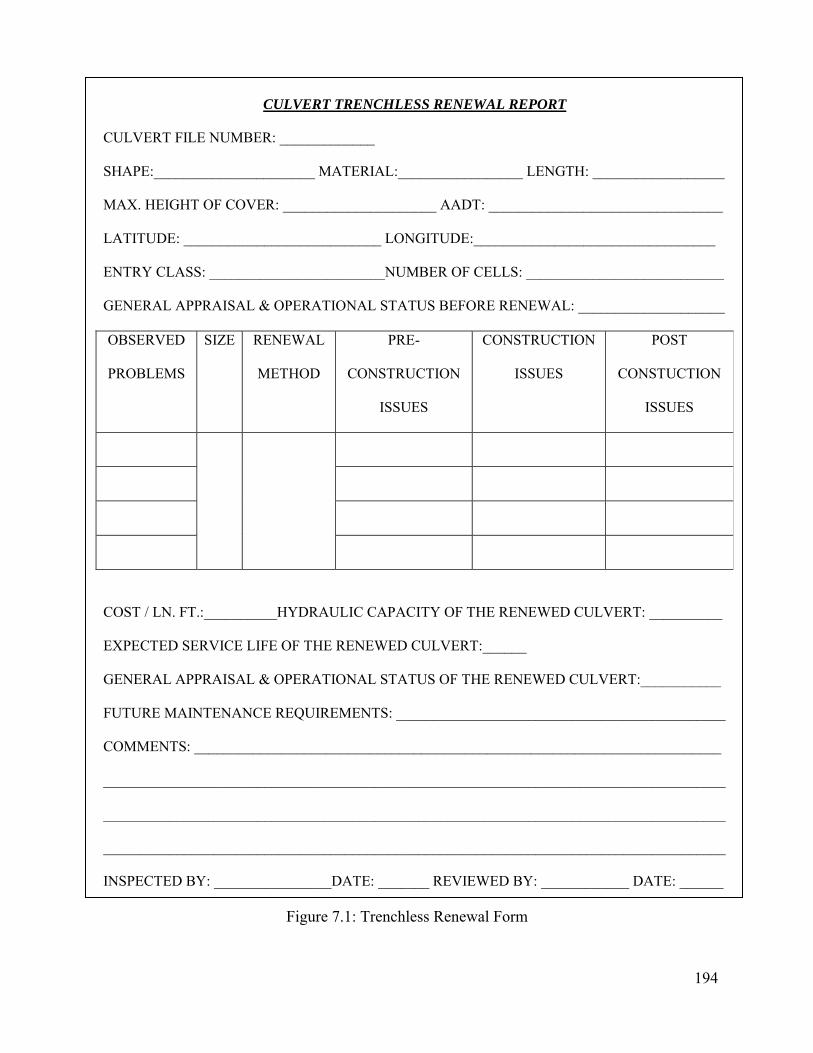
194
CULVERT TRENCHLESS RENEWAL REPORT
CULVERT FILE NUMBER: _____________
SHAPE:______________________ MATERIAL:_________________ LENGTH: __________________
MAX. HEIGHT OF COVER: _____________________ AADT: ________________________________
LATITUDE: ___________________________ LONGITUDE:_________________________________
ENTRY CLASS: ________________________NUMBER OF CELLS: ___________________________
GENERAL APPRAISAL & OPERATIONAL STATUS BEFORE RENEWAL: ____________________
OBSERVED
PROBLEMS
SIZE RENEWAL
METHOD
PRE-
CONSTRUCTION
ISSUES
CONSTRUCTION
ISSUES
POST
CONSTUCTION
ISSUES
COST / LN. FT.:__________HYDRAULIC CAPACITY OF THE RENEWED CULVERT: __________
EXPECTED SERVICE LIFE OF THE RENEWED CULVERT:______
GENERAL APPRAISAL & OPERATIONAL STATUS OF THE RENEWED CULVERT:___________
FUTURE MAINTENANCE REQUIREMENTS: _____________________________________________
COMMENTS: ________________________________________________________________________
_____________________________________________________________________________________
_____________________________________________________________________________________
_____________________________________________________________________________________
INSPECTED BY: ________________DATE: _______ REVIEWED BY: ____________ DATE: ______
Figure 7.1: Trenchless Renewal Form
195
Culvert Trenchless Renewal Report starts with the section regarding the general
information related to the particular culvert. This section involves the following items:
• Culvert File Number
• Shape
• Material
• Length
• Max. height of cover
• AADT (Annual Average Daily
Traffic)
• Latitude
• Longitude
• Entry Class
• Number of Cells
• General Appraisal & Operational
Status before renewal
Second section involves a table where the following items need to be filled:
• Observed Problems
• Size
• Renewal Method
• Pre-Construction Issues
• Construction Issues
• Post-Construction Issues
Final section involves the cost of the renewal project and characteristics of the culvert
after the renewal procedures. This section includes the following items:
• Cost / Linear foot
• Hydraulic Capacity of the renewed culvert
• Expected Service Life of the renewed culvert
• General appraisal and operational status of the renewed culvert
196
• Future Maintenance Requirements
The item “The Hydraulic Capacity of the renewed culvert” should be filled in the form in
terms of percentage of the culvert before the renewal.
The trenchless renewal report ends with the fields for additional comments, name of the
inspector and date, name of the reviewer and date fields.
7.2 Decision Support System
Decision making procedure regarding the renewal of culverts is a complex issue which
requires careful examination and evaluation of several factors such as sources of the problem,
characteristics of the culvert such as material, shape, and length, availability of funds, hydraulic
capacity, etc. Since each culvert is unique in terms of these factors it is not possible to generate a
universal solution to the problem. Moreover, each alternative trenchless technology method has
limitations and advantages over another. It is important to justify that the selected procedure fits
to the given situation even though it has some limitations. Therefore it is of utmost importance to
have a degree of flexibility in terms of adjusting the decision making procedure to the
circumstances at hand. The decision support system proposed in this project addresses this issue
by employing Analytical Hierarchy Process (AHP). The characteristics and procedure of AHP is
going to be covered in the following section.
7.2.1 Analytical Hierarchy Process (AHP)
Analytical Hierarchy Process is a decision making procedure developed by Professor
Thomas Saaty. The rationale behind the procedure involves constructing a hierarchy of the
objective, factors, sub-factors and alternatives, determining the priorities and ranking the
alternatives according to those priorities. The strength of this process comes from the ability of
incorporating qualitative data coming from judgment and experience, with the quantitative data.
197
Detailed information regarding the analytical hierarchy process can be found in “Decision
Making for Leaders: The Analytical Hierarchy Process for Decisions in a Complex World”
(Saaty 1982).
The steps followed in using Analytical Hierarchy Process are as follows:
1. Building the hierarchy
2. Comparing each factor in terms of importance, preference or contribution under the
higher level and show the comparisons using matrices.
3. Determining the priority vectors for all matrices.
4. Checking the matrices of pair-wise comparison in terms of consistency.
5. Determining the scores of alternatives and selecting the alternative with the highest score.
7.2.1.1 Building the hierarchy
Building the hierarchy involves 4 steps:
• Determining the overall objective
• Determining the factors which have an effect on achieving the objective
• Determining sub-factors under each factor
• Determining the alternatives
Once the objective, factors, sub-factors and alternatives are determined the hierarchy can be
drawn as in Figure 7.2. The hierarchy in this figure consists of two major factors (Factor A and
Factor B) and two sub-factors connected to each one of these major factors (Sub-Factors A-1, A-
2 and Sub-Factors B-1, B-2). There are two alternatives in this sample hierarchy, namely Alt 1
and Alt 2.

198
Figure 7.2: Sample Hierarchy
7.2.1.2 Comparison matrices
Comparison matrices are formed by comparing the importance, influence or contribution
of factors or sub-factors which are located on the same level. Pair wise comparison is performed
by listing all the items on the same level of the hierarchy on the rows and columns of the matrix
and filling the matrix with the values according to the table 7.1:
Intensity of importance Definition Explanation
1 Equal importance of both elements Two elements contribute equally to the property
3 Weak importance of one element over another
Experience and judgment slightly favor one element over
another
5 Essential or strong importance of one element over another
Experience and judgment strongly favor one element over
another
7 Demonstrated importance of one element over another
An element is strongly favored and its dominance is
demonstrated in practice
9 Absolute importance of one element over another
The evidence favoring one element over another is of the
highest possible order of affirmation
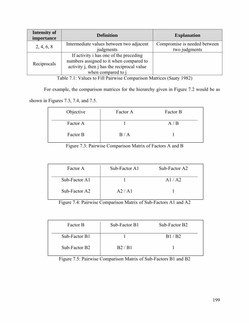
199
Intensity of importance Definition Explanation
2, 4, 6, 8 Intermediate values between two adjacent judgments
Compromise is needed between two judgments
Reciprocals
If activity i has one of the preceding numbers assigned to it when compared to activity j, then j has the reciprocal value
when compared to j
Table 7.1: Values to Fill Pairwise Comparison Matrices (Saaty 1982)
For example, the comparison matrices for the hierarchy given in Figure 7.2 would be as
shown in Figures 7.3, 7.4, and 7.5.
Objective Factor A Factor B
Factor A 1 A / B
Factor B B / A 1
Figure 7.3: Pairwise Comparison Matrix of Factors A and B
Factor A Sub-Factor A1 Sub-Factor A2
Sub-Factor A1 1 A1 / A2
Sub-Factor A2 A2 / A1 1
Figure 7.4: Pairwise Comparison Matrix of Sub-Factors A1 and A2
Factor B Sub-Factor B1 Sub-Factor B2
Sub-Factor B1 1 B1 / B2
Sub-Factor B2 B2 / B1 1
Figure 7.5: Pairwise Comparison Matrix of Sub-Factors B1 and B2

200
7.2.1.3 Determining the priority vectors
Priority vectors are determined in order to convert the pair-wise comparison matrices into
the weight of each factor and sub-factor. Average of the normalized columns which is an
approximate method of determining eigenvectors is going to be used in this study. This method
involves the following steps:
• Summation of the values in each column of the matrix
• Dividing each value to the corresponding column total
• Taking the average of the values in each row
As an illustration the priority vector for the pair-wise comparison matrix given in Figure 7.6
is found as follows (see Figures 7.7 and 7.8):
Objective Factor A Factor B
Factor A 1 2
Factor B 1 / 2 1
Figure 7.6: Sample Pairwise Comparison Matrix of Factors A and B
Step 1: Calculating the column totals:
Objective Factor A Factor B
Factor A 1 2
Factor B 1 / 2 1
Total 1.5 3
Figure 7.7: Calculation of Priority Vectors for the Matrix Given in Figure 6.6 - Step 1
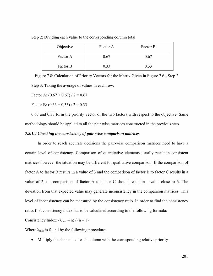
201
Step 2: Dividing each value to the corresponding column total:
Objective Factor A Factor B
Factor A 0.67 0.67
Factor B 0.33 0.33
Figure 7.8: Calculation of Priority Vectors for the Matrix Given in Figure 7.6 - Step 2
Step 3: Taking the average of values in each row:
Factor A: (0.67 + 0.67) / 2 = 0.67
Factor B: (0.33 + 0.33) / 2 = 0.33
0.67 and 0.33 form the priority vector of the two factors with respect to the objective. Same
methodology should be applied to all the pair wise matrices constructed in the previous step.
7.2.1.4 Checking the consistency of pair-wise comparison matrices
In order to reach accurate decisions the pair-wise comparison matrices need to have a
certain level of consistency. Comparison of quantitative elements usually result in consistent
matrices however the situation may be different for qualitative comparison. If the comparison of
factor A to factor B results in a value of 3 and the comparison of factor B to factor C results in a
value of 2, the comparison of factor A to factor C should result in a value close to 6. The
deviation from that expected value may generate inconsistency in the comparison matrices. This
level of inconsistency can be measured by the consistency ratio. In order to find the consistency
ratio, first consistency index has to be calculated according to the following formula:
Consistency Index: (λmax – n) / (n – 1)
Where λmax is found by the following procedure:
• Multiply the elements of each column with the corresponding relative priority

202
• Sum the elements in each row of the resulting matrix.
• Divide the summation of each row with the corresponding relative priority
• Find the average of the resultant numbers from the last step.
Once the consistency index is found it should be divided by the random consistency number to
find the consistency ratio. The values of random consistency numbers can be found in Saaty
1982. These values are given in table 7.2:
n Random consistency1 0.00 2 0.00 3 0.58 4 0.90 5 1.12 6 1.24 7 1.32 8 1.41 9 1.45 10 1.49
Table 7.2: Random Consistency Values (Saaty 1982)
If the consistency ratio is determined to be higher than 0.10, the inconsistency should be
corrected.
7.2.1.5 Determining the scores of alternatives
In order to find the alternative which best suits the given hierarchy the weights of all the
sub-factors which are linked to the alternatives should be calculated. This is performed by
multiplying the relative priority of the higher factors with the relative priority of sub-factors
which are connected to these factors. For example if Factor A is connected to sub-factors A1 and
A2 and these sub-factors are connected to the alternatives x and y the weights of sub-factors A1
and A2 should be calculated by multiplying the relative priority of factor A with the relative
priority of sub-factor A1 and with the relative priority of sub-factor A2 respectively. If factor A
has a relative priority of 0.67 and sub-factor A1 has a relative priority of 0.33 and sub-factor A2
203
has a relative propriety of 0.67, the final relative priority of sub-factor A1 would be 0.67
multiplied by 0.33 and the final relative propriety of sub-factor A2 would be 0.67 multiplied by
0.67.
Once all the weights for all sub-factors are calculated the alternatives should be compared
against each other in terms of satisfying each sub-factor. Pair-wise comparison matrices which
involve the comparisons of alternatives with respect to each sub-factor should be created. The
priority vectors of these matrices should be calculated.
The overall scores for all alternatives are calculated by multiplying the priority vector of
alternatives with the transpose of sub-factor relative priorities. The alternative with the highest
score satisfies the given conditions best and therefore selected as the best alternative.
7.2.2 Decision Support System Incorporating AHP and ODOT Inspection Procedures
In this section a decision support system which combines the analytical hierarchy process
(AHP) with the Ohio Department of Transportation’s Culvert Inspection Procedures is
developed. The outline of the procedure is going to be presented and an illustrative example is
going to be used to further explain each step. One of main reasons of selecting AHP is the
flexibility of the method which enables the user to adjust it according to the site-specific
conditions at hand. The factors, sub-factors and the alternatives among which a decision must be
made may be different for each culvert therefore the example provided in this section only serves
as an illustrative example. Decision makers should make the required modifications in order to
use this method for the specific site conditions.
The steps of the proposed decision support system are as follows:
Step 1: Determine the structural condition of the culvert
Step 2: Identify the type of treatment required
204
Step 3: Generate the potential renewal alternatives
Step 4: Identify the site-specific factors and sub-factors
Step 5: Build the hierarchy
Step 6: Construct the comparison matrices
Step 7: Check the consistency of comparison matrices
Step 8: Find the priority vectors for all sub-factors
Step 9: Create pair-wise comparison matrices for alternatives and sub-factors
Step 10: Select the alternative with the highest score
Illustrative example:
An agency wishes to find the optimum way to renew their culvert which has serious
problems associated with the structural components. Suppose that, the culvert to be renewed is a
corrugated metal pipe under 12 ft depth of height and having a diameter of 65 inches. Culvert
does not have misalignment or excessive deformations. The site specific factors are determined
as cost, working space requirement, design life of the renewed culvert, previous experience with
the method, hydraulic capacity of the renewed culvert and contractor availability.
Step 1: Determine the structural condition of the culvert
The condition of the culvert is the most important input variable of the decision support
system since it dictates the kind of renewal that needs to be performed. The information
regarding the structural condition of the culvert can be taken from the output of inspection
procedures performed by following the Ohio Culvert Management Manual. The general
appraisal item of the inspection form identifies the structural condition of the culvert according
to table 7.3. This information is going to be used in the steps that follow in order to select the
type of renewal that is required.
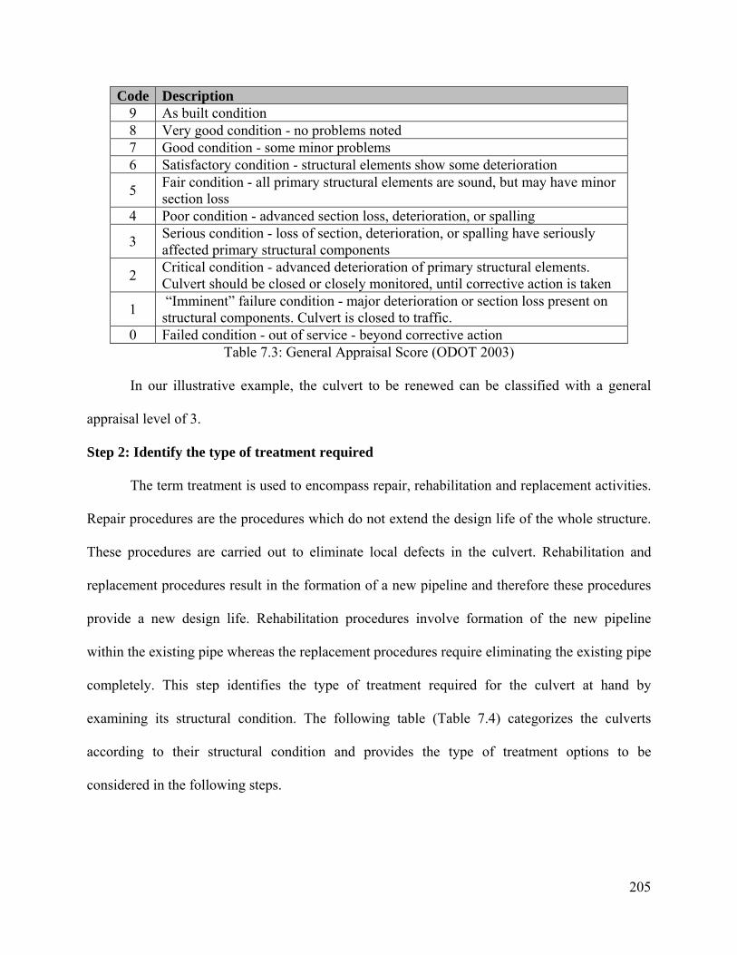
205
Code Description 9 As built condition 8 Very good condition - no problems noted 7 Good condition - some minor problems 6 Satisfactory condition - structural elements show some deterioration
5 Fair condition - all primary structural elements are sound, but may have minor section loss
4 Poor condition - advanced section loss, deterioration, or spalling
3 Serious condition - loss of section, deterioration, or spalling have seriously affected primary structural components
2 Critical condition - advanced deterioration of primary structural elements. Culvert should be closed or closely monitored, until corrective action is taken
1 “Imminent” failure condition - major deterioration or section loss present on structural components. Culvert is closed to traffic.
0 Failed condition - out of service - beyond corrective action Table 7.3: General Appraisal Score (ODOT 2003)
In our illustrative example, the culvert to be renewed can be classified with a general
appraisal level of 3.
Step 2: Identify the type of treatment required
The term treatment is used to encompass repair, rehabilitation and replacement activities.
Repair procedures are the procedures which do not extend the design life of the whole structure.
These procedures are carried out to eliminate local defects in the culvert. Rehabilitation and
replacement procedures result in the formation of a new pipeline and therefore these procedures
provide a new design life. Rehabilitation procedures involve formation of the new pipeline
within the existing pipe whereas the replacement procedures require eliminating the existing pipe
completely. This step identifies the type of treatment required for the culvert at hand by
examining its structural condition. The following table (Table 7.4) categorizes the culverts
according to their structural condition and provides the type of treatment options to be
considered in the following steps.
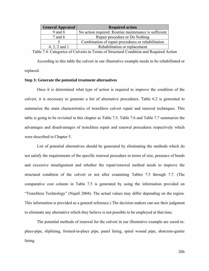
206
General Appraisal Required action 9 and 8 No action required. Routine maintenance is sufficient 7 and 6 Repair procedure or Do Nothing
5 Combination of repair procedures or rehabilitation 4, 3, 2 and 1 Rehabilitation or replacement
Table 7.4: Categories of Culverts in Terms of Structural Condition and Required Action
According to this table the culvert in our illustrative example needs to be rehabilitated or
replaced.
Step 3: Generate the potential treatment alternatives
Once it is determined what type of action is required to improve the condition of the
culvert, it is necessary to generate a list of alternative procedures. Table 6.2 is generated to
summarize the main characteristics of trenchless culvert repair and renewal techniques. This
table is going to be revisited in this chapter as Table 7.5. Table 7.6 and Table 7.7 summarize the
advantages and disadvantages of trenchless repair and renewal procedures respectively which
were described in Chapter 5.
List of potential alternatives should be generated by eliminating the methods which do
not satisfy the requirements of the specific renewal procedure in terms of size, presence of bends
and excessive misalignment and whether the repair/renewal method needs to improve the
structural condition of the culvert or not after examining Tables 7.5 through 7.7. (The
comparative cost column in Table 7.5 is generated by using the information provided on
“Trenchless Technology” (Najafi 2004). The actual values may differ depending on the region.
This information is provided as a general reference.) The decision makers can use their judgment
to eliminate any alternative which they believe is not possible to be employed at that time.
The potential methods of renewal for the culvert in our illustrative example are cured-in-
place-pipe, sliplining, formed-in-place pipe, panel lining, spiral wound pipe, shotcrete-gunite
lining.
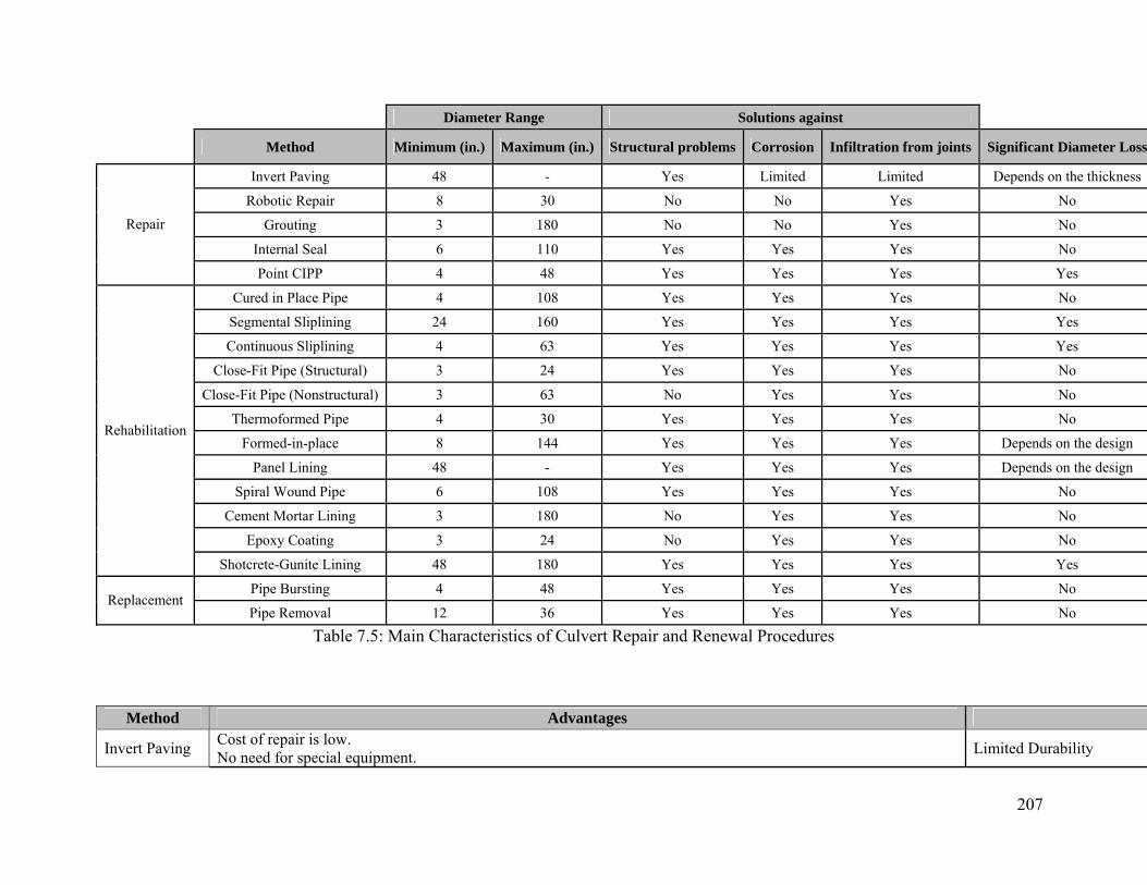
207
Diameter Range Solutions against
Method Minimum (in.) Maximum (in.) Structural problems Corrosion Infiltration from joints Significant Diameter Loss
Invert Paving 48 - Yes Limited Limited Depends on the thickness
Robotic Repair 8 30 No No Yes No
Grouting 3 180 No No Yes No
Internal Seal 6 110 Yes Yes Yes No
Repair
Point CIPP 4 48 Yes Yes Yes Yes
Cured in Place Pipe 4 108 Yes Yes Yes No
Segmental Sliplining 24 160 Yes Yes Yes Yes
Continuous Sliplining 4 63 Yes Yes Yes Yes
Close-Fit Pipe (Structural) 3 24 Yes Yes Yes No
Close-Fit Pipe (Nonstructural) 3 63 No Yes Yes No
Thermoformed Pipe 4 30 Yes Yes Yes No
Formed-in-place 8 144 Yes Yes Yes Depends on the design
Panel Lining 48 - Yes Yes Yes Depends on the design
Spiral Wound Pipe 6 108 Yes Yes Yes No
Cement Mortar Lining 3 180 No Yes Yes No
Epoxy Coating 3 24 No Yes Yes No
Rehabilitation
Shotcrete-Gunite Lining 48 180 Yes Yes Yes Yes
Pipe Bursting 4 48 Yes Yes Yes No Replacement
Pipe Removal 12 36 Yes Yes Yes No
Table 7.5: Main Characteristics of Culvert Repair and Renewal Procedures
Method Advantages
Invert Paving Cost of repair is low. No need for special equipment. Limited Durability

208
Robotic Repair Point repair of the pipe is handled with good precision. Repair method provides a better infiltration barrier and helps in restoring the structural integrity of the existing pipe.
Robotic repair cannot be usDefects larger than 2 inchesEquipments used in robotic
Grouting Low cost. Infiltration and exfiltration problems can be eliminated with this method.
This method does not enhanDurability of the grout is us
Internal Seal This method offers structural solutions. This method can be applied to solve problems such as pipe breakage, joint settlement and longitudinal cracks. Gravity sewers, culverts, and pressure pipes can be repaired without excavation.
Internal sleeve may cause aThis method is applicable to
Point CIPP
Point CIPP adheres to the existing pipe tightly and eliminates infiltration. The repair procedure may usually be performed without diverting the existing flow. This method offers structural solution to the defected pipe segment. Lining does not obscure the flow due to tapered smooth ends.
This method does not improPoint CIPP method may be Hydraulic capacity may be
Table 7.6: Advantages and Limitations of Trenchless Repair Procedures
Method Advantages
Cured in Place Pipe (CIPP)
CIPP eliminates the need for grouting due to the tight fit with the existing pipe. CIPP offers an improved flow capacity due to its smooth interior Pipes with noncircular shapes can be renewed without decreasing the flow capacity. CIPP can be used in renewal of pipes with bends and deformations. Manholes can be used to access the existing pipe.
The lining materiaThe existing flow mLiner pipe ends or Monitoring, inspecRemoving the curiLining can be affecCIPP can be more
Sliplining
Special expensive equipments are not needed. It is a simple method applicable to both gravity and pressure pipelines. It offers both structural and nonstructural solutions. This method allows for renewal without diverting the actual flow.
Pipe diameter is reA pit needs to be cLaterals need to beThe annular space
Close-Fit Pipe
The new polyethylene pipe used in renewing the existing pipe is produced in a controlled environment. The cross sectional loss is minimal. This method is useful in eliminating internal corrosion problems. Pipes with bends up to 45 degrees can be renewed by MFP. Installations can be performed up to 1000 ft. It is possible to establish the lateral connections internally.
Diameter range anThe new butt-fusedPipes with varyingIn general, an inserUsually the existinValves and connec
Thermoformed Pipe This method offers fast installation and high quality due to the factory manufacturing of the liner pipe. This method does not involve discharge of harmful chemicals to the environment Excavation risk is lower due to start/stop capability of many thermoformed pipe methods.
This method is appDrive lengths are sIn fused and expan
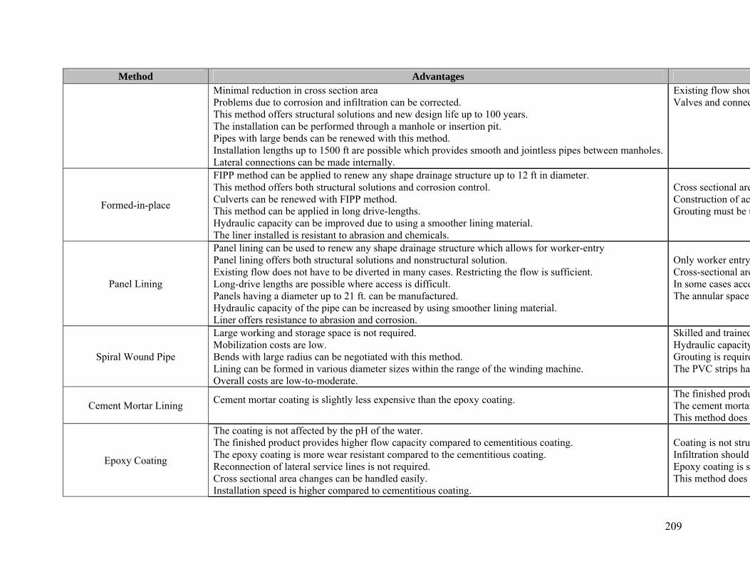
209
Method Advantages Minimal reduction in cross section area Problems due to corrosion and infiltration can be corrected. This method offers structural solutions and new design life up to 100 years. The installation can be performed through a manhole or insertion pit. Pipes with large bends can be renewed with this method. Installation lengths up to 1500 ft are possible which provides smooth and jointless pipes between manholes. Lateral connections can be made internally.
Existing flow shouValves and connec
Formed-in-place
FIPP method can be applied to renew any shape drainage structure up to 12 ft in diameter. This method offers both structural solutions and corrosion control. Culverts can be renewed with FIPP method. This method can be applied in long drive-lengths. Hydraulic capacity can be improved due to using a smoother lining material. The liner installed is resistant to abrasion and chemicals.
Cross sectional areConstruction of acGrouting must be u
Panel Lining
Panel lining can be used to renew any shape drainage structure which allows for worker-entry Panel lining offers both structural solutions and nonstructural solution. Existing flow does not have to be diverted in many cases. Restricting the flow is sufficient. Long-drive lengths are possible where access is difficult. Panels having a diameter up to 21 ft. can be manufactured. Hydraulic capacity of the pipe can be increased by using smoother lining material. Liner offers resistance to abrasion and corrosion.
Only worker entryCross-sectional areIn some cases acceThe annular space
Spiral Wound Pipe
Large working and storage space is not required. Mobilization costs are low. Bends with large radius can be negotiated with this method. Lining can be formed in various diameter sizes within the range of the winding machine. Overall costs are low-to-moderate.
Skilled and trainedHydraulic capacityGrouting is requireThe PVC strips hav
Cement Mortar Lining Cement mortar coating is slightly less expensive than the epoxy coating.
The finished produThe cement mortarThis method does n
Epoxy Coating
The coating is not affected by the pH of the water. The finished product provides higher flow capacity compared to cementitious coating. The epoxy coating is more wear resistant compared to the cementitious coating. Reconnection of lateral service lines is not required. Cross sectional area changes can be handled easily. Installation speed is higher compared to cementitious coating.
Coating is not struInfiltration should Epoxy coating is sThis method does n
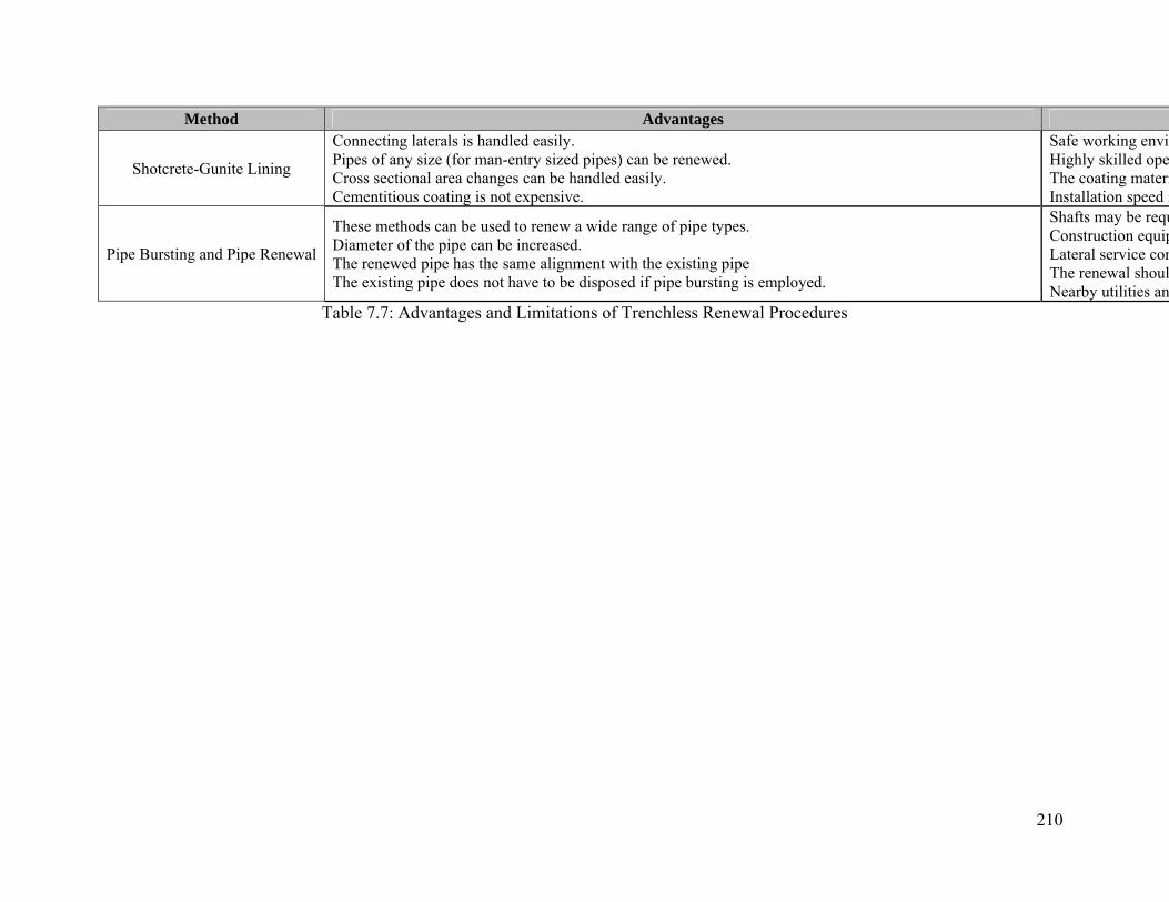
210
Method Advantages
Shotcrete-Gunite Lining
Connecting laterals is handled easily. Pipes of any size (for man-entry sized pipes) can be renewed. Cross sectional area changes can be handled easily. Cementitious coating is not expensive.
Safe working envirHighly skilled opeThe coating materiInstallation speed i
Pipe Bursting and Pipe Renewal
These methods can be used to renew a wide range of pipe types. Diameter of the pipe can be increased. The renewed pipe has the same alignment with the existing pipe The existing pipe does not have to be disposed if pipe bursting is employed.
Shafts may be requConstruction equipLateral service conThe renewal shoulNearby utilities an
Table 7.7: Advantages and Limitations of Trenchless Renewal Procedures
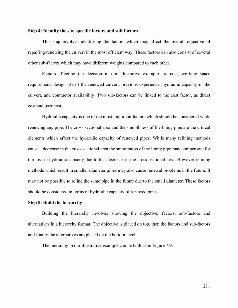
211
Step 4: Identify the site-specific factors and sub-factors
This step involves identifying the factors which may affect the overall objective of
repairing/renewing the culvert in the most efficient way. These factors can also consist of several
other sub-factors which may have different weights compared to each other.
Factors affecting the decision in our illustrative example are cost, working space
requirement, design life of the renewed culvert, previous experience, hydraulic capacity of the
culvert, and contractor availability. Two sub-factors can be linked to the cost factor, as direct
cost and user cost.
Hydraulic capacity is one of the most important factors which should be considered while
renewing any pipe. The cross sectional area and the smoothness of the lining pipe are the critical
elements which affect the hydraulic capacity of renewed pipes. While many relining methods
cause a decrease in the cross sectional area the smoothness of the lining pipe may compensate for
the loss in hydraulic capacity due to that decrease in the cross sectional area. However relining
methods which result in smaller diameter pipes may also cause renewal problems in the future. It
may not be possible to reline the same pipe in the future due to the small diameter. These factors
should be considered in terms of hydraulic capacity of renewed pipes.
Step 5: Build the hierarchy
Building the hierarchy involves showing the objective, factors, sub-factors and
alternatives in a hierarchy format. The objective is placed on top, then the factors and sub-factors
and finally the alternatives are placed on the bottom level.
The hierarchy in our illustrative example can be built as in Figure 7.9:
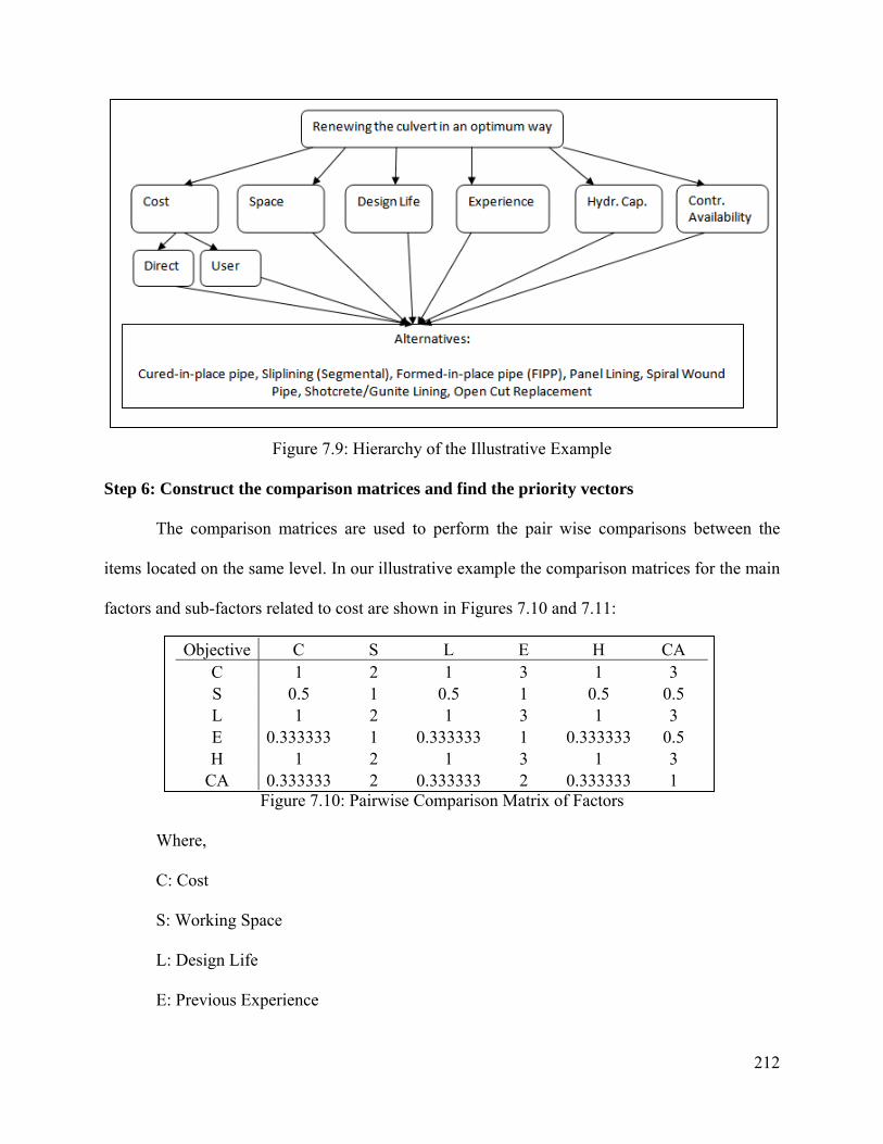
212
Figure 7.9: Hierarchy of the Illustrative Example
Step 6: Construct the comparison matrices and find the priority vectors
The comparison matrices are used to perform the pair wise comparisons between the
items located on the same level. In our illustrative example the comparison matrices for the main
factors and sub-factors related to cost are shown in Figures 7.10 and 7.11:
Objective C S L E H CA C 1 2 1 3 1 3 S 0.5 1 0.5 1 0.5 0.5 L 1 2 1 3 1 3 E 0.333333 1 0.333333 1 0.333333 0.5 H 1 2 1 3 1 3
CA 0.333333 2 0.333333 2 0.333333 1 Figure 7.10: Pairwise Comparison Matrix of Factors
Where,
C: Cost
S: Working Space
L: Design Life
E: Previous Experience
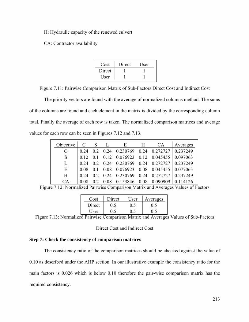
213
H: Hydraulic capacity of the renewed culvert
CA: Contractor availability
Figure 7.11: Pairwise Comparison Matrix of Sub-Factors Direct Cost and Indirect Cost
The priority vectors are found with the average of normalized columns method. The sums
of the columns are found and each element in the matrix is divided by the corresponding column
total. Finally the average of each row is taken. The normalized comparison matrices and average
values for each row can be seen in Figures 7.12 and 7.13.
Objective C S L E H CA Averages C 0.24 0.2 0.24 0.230769 0.24 0.272727 0.237249 S 0.12 0.1 0.12 0.076923 0.12 0.045455 0.097063 L 0.24 0.2 0.24 0.230769 0.24 0.272727 0.237249 E 0.08 0.1 0.08 0.076923 0.08 0.045455 0.077063 H 0.24 0.2 0.24 0.230769 0.24 0.272727 0.237249
CA 0.08 0.2 0.08 0.153846 0.08 0.090909 0.114126 Figure 7.12: Normalized Pairwise Comparison Matrix and Averages Values of Factors
Cost Direct User AveragesDirect 0.5 0.5 0.5 User 0.5 0.5 0.5
Figure 7.13: Normalized Pairwise Comparison Matrix and Averages Values of Sub-Factors
Direct Cost and Indirect Cost
Step 7: Check the consistency of comparison matrices
The consistency ratio of the comparison matrices should be checked against the value of
0.10 as described under the AHP section. In our illustrative example the consistency ratio for the
main factors is 0.026 which is below 0.10 therefore the pair-wise comparison matrix has the
required consistency.
Cost Direct User Direct 1 1 User 1 1
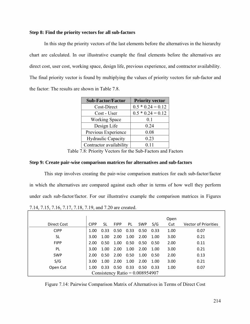
214
Step 8: Find the priority vectors for all sub-factors
In this step the priority vectors of the last elements before the alternatives in the hierarchy
chart are calculated. In our illustrative example the final elements before the alternatives are
direct cost, user cost, working space, design life, previous experience, and contractor availability.
The final priority vector is found by multiplying the values of priority vectors for sub-factor and
the factor: The results are shown in Table 7.8.
Sub-Factor/Factor Priority vector Cost-Direct 0.5 * 0.24 = 0.12Cost - User 0.5 * 0.24 = 0.12
Working Space 0.1 Design Life 0.24
Previous Experience 0.08 Hydraulic Capacity 0.23
Contractor availability 0.11 Table 7.8: Priority Vectors for the Sub-Factors and Factors
Step 9: Create pair-wise comparison matrices for alternatives and sub-factors
This step involves creating the pair-wise comparison matrices for each sub-factor/factor
in which the alternatives are compared against each other in terms of how well they perform
under each sub-factor/factor. For our illustrative example the comparison matrices in Figures
7.14, 7.15, 7.16, 7.17, 7.18, 7.19, and 7.20 are created.
Direct Cost CIPP SL FIPP PL SWP S/G Open Cut Vector of Priorities
CIPP 1.00 0.33 0.50 0.33 0.50 0.33 1.00 0.07 SL 3.00 1.00 2.00 1.00 2.00 1.00 3.00 0.21 FIPP 2.00 0.50 1.00 0.50 0.50 0.50 2.00 0.11 PL 3.00 1.00 2.00 1.00 2.00 1.00 3.00 0.21 SWP 2.00 0.50 2.00 0.50 1.00 0.50 2.00 0.13 S/G 3.00 1.00 2.00 1.00 2.00 1.00 3.00 0.21
Open Cut 1.00 0.33 0.50 0.33 0.50 0.33 1.00 0.07 Consistency Ratio = 0.008954907
Figure 7.14: Pairwise Comparison Matrix of Alternatives in Terms of Direct Cost
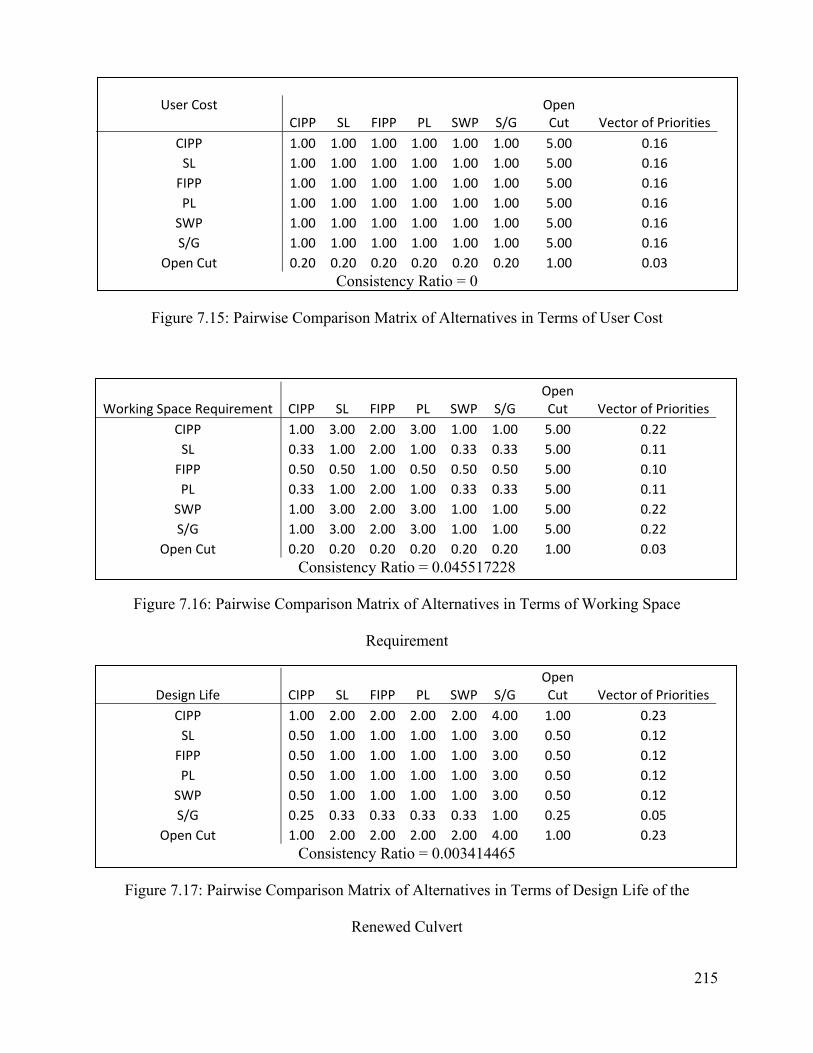
215
User Cost CIPP SL FIPP PL SWP S/G
Open Cut Vector of Priorities
CIPP 1.00 1.00 1.00 1.00 1.00 1.00 5.00 0.16 SL 1.00 1.00 1.00 1.00 1.00 1.00 5.00 0.16 FIPP 1.00 1.00 1.00 1.00 1.00 1.00 5.00 0.16 PL 1.00 1.00 1.00 1.00 1.00 1.00 5.00 0.16 SWP 1.00 1.00 1.00 1.00 1.00 1.00 5.00 0.16 S/G 1.00 1.00 1.00 1.00 1.00 1.00 5.00 0.16
Open Cut 0.20 0.20 0.20 0.20 0.20 0.20 1.00 0.03 Consistency Ratio = 0
Figure 7.15: Pairwise Comparison Matrix of Alternatives in Terms of User Cost
Working Space Requirement CIPP SL FIPP PL SWP S/G Open Cut Vector of Priorities
CIPP 1.00 3.00 2.00 3.00 1.00 1.00 5.00 0.22 SL 0.33 1.00 2.00 1.00 0.33 0.33 5.00 0.11 FIPP 0.50 0.50 1.00 0.50 0.50 0.50 5.00 0.10 PL 0.33 1.00 2.00 1.00 0.33 0.33 5.00 0.11 SWP 1.00 3.00 2.00 3.00 1.00 1.00 5.00 0.22 S/G 1.00 3.00 2.00 3.00 1.00 1.00 5.00 0.22
Open Cut 0.20 0.20 0.20 0.20 0.20 0.20 1.00 0.03 Consistency Ratio = 0.045517228
Figure 7.16: Pairwise Comparison Matrix of Alternatives in Terms of Working Space
Requirement
Design Life CIPP SL FIPP PL SWP S/G Open Cut Vector of Priorities
CIPP 1.00 2.00 2.00 2.00 2.00 4.00 1.00 0.23 SL 0.50 1.00 1.00 1.00 1.00 3.00 0.50 0.12 FIPP 0.50 1.00 1.00 1.00 1.00 3.00 0.50 0.12 PL 0.50 1.00 1.00 1.00 1.00 3.00 0.50 0.12 SWP 0.50 1.00 1.00 1.00 1.00 3.00 0.50 0.12 S/G 0.25 0.33 0.33 0.33 0.33 1.00 0.25 0.05
Open Cut 1.00 2.00 2.00 2.00 2.00 4.00 1.00 0.23 Consistency Ratio = 0.003414465
Figure 7.17: Pairwise Comparison Matrix of Alternatives in Terms of Design Life of the
Renewed Culvert
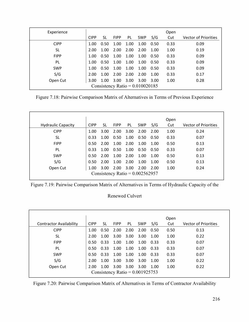
216
Experience CIPP SL FIPP PL SWP S/G
Open Cut Vector of Priorities
CIPP 1.00 0.50 1.00 1.00 1.00 0.50 0.33 0.09 SL 2.00 1.00 2.00 2.00 2.00 1.00 1.00 0.19 FIPP 1.00 0.50 1.00 1.00 1.00 0.50 0.33 0.09 PL 1.00 0.50 1.00 1.00 1.00 0.50 0.33 0.09 SWP 1.00 0.50 1.00 1.00 1.00 0.50 0.33 0.09 S/G 2.00 1.00 2.00 2.00 2.00 1.00 0.33 0.17
Open Cut 3.00 1.00 3.00 3.00 3.00 3.00 1.00 0.28 Consistency Ratio = 0.010020185
Figure 7.18: Pairwise Comparison Matrix of Alternatives in Terms of Previous Experience
Hydraulic Capacity CIPP SL FIPP PL SWP S/G Open Cut Vector of Priorities
CIPP 1.00 3.00 2.00 3.00 2.00 2.00 1.00 0.24 SL 0.33 1.00 0.50 1.00 0.50 0.50 0.33 0.07 FIPP 0.50 2.00 1.00 2.00 1.00 1.00 0.50 0.13 PL 0.33 1.00 0.50 1.00 0.50 0.50 0.33 0.07 SWP 0.50 2.00 1.00 2.00 1.00 1.00 0.50 0.13 S/G 0.50 2.00 1.00 2.00 1.00 1.00 0.50 0.13
Open Cut 1.00 3.00 2.00 3.00 2.00 2.00 1.00 0.24 Consistency Ratio = 0.002562957
Figure 7.19: Pairwise Comparison Matrix of Alternatives in Terms of Hydraulic Capacity of the
Renewed Culvert
Contractor Availability CIPP SL FIPP PL SWP S/G Open Cut Vector of Priorities
CIPP 1.00 0.50 2.00 2.00 2.00 0.50 0.50 0.13 SL 2.00 1.00 3.00 3.00 3.00 1.00 1.00 0.22 FIPP 0.50 0.33 1.00 1.00 1.00 0.33 0.33 0.07 PL 0.50 0.33 1.00 1.00 1.00 0.33 0.33 0.07 SWP 0.50 0.33 1.00 1.00 1.00 0.33 0.33 0.07 S/G 2.00 1.00 3.00 3.00 3.00 1.00 1.00 0.22
Open Cut 2.00 1.00 3.00 3.00 3.00 1.00 1.00 0.22 Consistency Ratio = 0.001925753
Figure 7.20: Pairwise Comparison Matrix of Alternatives in Terms of Contractor Availability
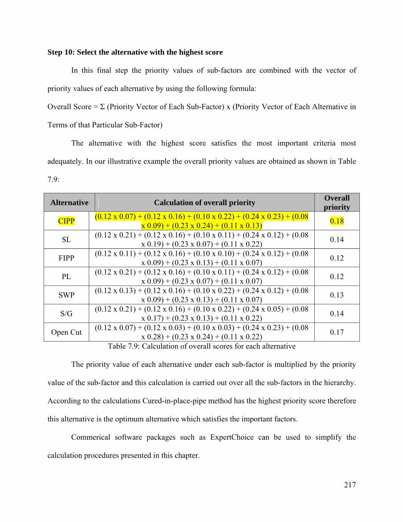
217
Step 10: Select the alternative with the highest score
In this final step the priority values of sub-factors are combined with the vector of
priority values of each alternative by using the following formula:
Overall Score = Σ (Priority Vector of Each Sub-Factor) x (Priority Vector of Each Alternative in
Terms of that Particular Sub-Factor)
The alternative with the highest score satisfies the most important criteria most
adequately. In our illustrative example the overall priority values are obtained as shown in Table
7.9:
Alternative Calculation of overall priority Overall priority
CIPP (0.12 x 0.07) + (0.12 x 0.16) + (0.10 x 0.22) + (0.24 x 0.23) + (0.08 x 0.09) + (0.23 x 0.24) + (0.11 x 0.13) 0.18
SL (0.12 x 0.21) + (0.12 x 0.16) + (0.10 x 0.11) + (0.24 x 0.12) + (0.08 x 0.19) + (0.23 x 0.07) + (0.11 x 0.22) 0.14
FIPP (0.12 x 0.11) + (0.12 x 0.16) + (0.10 x 0.10) + (0.24 x 0.12) + (0.08 x 0.09) + (0.23 x 0.13) + (0.11 x 0.07) 0.12
PL (0.12 x 0.21) + (0.12 x 0.16) + (0.10 x 0.11) + (0.24 x 0.12) + (0.08 x 0.09) + (0.23 x 0.07) + (0.11 x 0.07) 0.12
SWP (0.12 x 0.13) + (0.12 x 0.16) + (0.10 x 0.22) + (0.24 x 0.12) + (0.08 x 0.09) + (0.23 x 0.13) + (0.11 x 0.07) 0.13
S/G (0.12 x 0.21) + (0.12 x 0.16) + (0.10 x 0.22) + (0.24 x 0.05) + (0.08 x 0.17) + (0.23 x 0.13) + (0.11 x 0.22) 0.14
Open Cut (0.12 x 0.07) + (0.12 x 0.03) + (0.10 x 0.03) + (0.24 x 0.23) + (0.08 x 0.28) + (0.23 x 0.24) + (0.11 x 0.22) 0.17
Table 7.9: Calculation of overall scores for each alternative
The priority value of each alternative under each sub-factor is multiplied by the priority
value of the sub-factor and this calculation is carried out over all the sub-factors in the hierarchy.
According to the calculations Cured-in-place-pipe method has the highest priority score therefore
this alternative is the optimum alternative which satisfies the important factors.
Commerical software packages such as ExpertChoice can be used to simplify the
calculation procedures presented in this chapter.

218
8. Conclusions and Recommendations
8.1 Conclusions
Trenchless technology methods offer both structural and non-structural solutions to
buried pipe problems without incurring damage to adjacent utilities, infrastructure or pavement,
and with minimal disruption or inconvenience to the public. Such techniques have been widely
used for repair and renewal of sewer and water pipes. The present study focuses on the collection
of information regarding the main characteristics of trenchless technologies including their
advantages and limitations, and examines the applicability of these methods to culverts. The
tasks performed in this study include:
Task 1: Review literature and case studies
Task 2: Review factors affecting culvert deteriorations
Task 3: Review and survey existing trenchless technology methods with potential use for
renewal of culverts and drainage structures and identify capabilities and limitations of each of
these methods.
Task 4: Develop inspection, asset management and maintenance requirements of renewed
culverts with trenchless technology methods.
Task 5: Develop modification requirements in existing trenchless technologies to be used
in culverts and drainage structures.
Task 6: Collaborate with ODOT and MDOT to establish a database and decision support
system for selection of appropriate trenchless technology methods
Task 7: Develop course modules for culvert asset management using trenchless
technologies.
219
As part of this study, an extensive literature review was performed examining major civil
engineering publications and databases provided by the American Society of Civil Engineers
(ASCE), Federal Highway Administration (FHWA), Transportation Research Board (TRB)
Records, American Association of State Highway and Transportation Officials (AASHTO) and
the National Cooperative Highway Research Program (NCHRP). A survey of state departments
of transportation (DOTs) was conducted to obtain information regarding current culvert
maintenance practices and trenchless repair and renewal methods. In addition, a survey of
technology providers was prepared and conducted in order to gain more comprehensive
information on the subject.
The collected information was used to develop an asset management strategy for culverts.
The applicable characteristics and range of application of trenchless repair and renewal methods
has been conveniently summarized in a table, and limitations of trenchless technologies in terms
of applicability to culverts has been investigated. A database form was created to record the
characteristics of any future trenchless repair and renewal job. A decision support system which
links the inspection procedures of Ohio Department of Transportation’s Culvert Management
Manual to appropriate trenchless repair and renewal methods has also been developed.
The proposed decision system utilizes the Analytical Hierarchy Process (AHP) which
provides the required flexibility to the user in terms of adjusting the procedure according to the
situation at hand. Each culvert can be considered unique in terms of job site conditions and
structural conditions. Therefore factors and alternatives for each jobsite should be evaluated
before making decisions regarding the appropriate repair and renewal procedures for culverts. A
method that may work well for one culvert situation may not be optimum or appropriate for
another. For this reason, the decision support system contained in this report, provides a
220
methodology to the users that enables them to enter the factors and alternatives for each jobsite
and to identify the optimum procedure(s) depending on these factors and alternatives.
8.2 Recommendations for future studies
It is to be expected that new and improved methods of trenchless technology will
continue to evolve due to technological improvements and new discoveries in material science,
accelerated by increasing demand as growing urbanization and traffic volume force agencies to
employ non-disruptive trenchless technologies. The continuing development of trenchless
technology methods and associated experiences will provide additional information in the future.
The investigators suggest that researchers update the technologies and methodologies presented
in this research project on an ongoing basis.
221
9. References
AASHTO. (1999). “Highway Drainage Guidelines for Culvert Inspection and Renewal,
Volume XIV,” Task Force on Hydrology and Hydraulics, AASHTO Highway Subcommittee
on Design.
Ablin R. L., and Stram M. (2005). “City of Glendale Emergency Sewer Rehabilitation.” Proc.,
No-Dig 2005 (CD-ROM), NASTT, Arlington, VA.
Adams, D. N., Muindi, Y., and Selig, E. T. (1989). “Polyethylene Pipe Under High Fill”
Transportation Research Record (TRR), Journal of Transportation Research Board, Vol. 1231,
National Research Council, Washington, D.C., pp 88-95
Allouche E. N., Montes C., and Diaz E. I. (2007). “A New Generation of Cementitious
Materials for Mortar Lining of Buried Pipes.” Proc. Pipelines 2007 (CD-ROM), ASCE,
Reston, VA.
Amyot C., Knight M. A., and Garibaldi B. (2003). “City of Waterloo Case Study Cement
Mortar vs. Epoxy Lining of Watermains for Improved Water Quality.” Proc., No-Dig 2003
(CD-ROM), NASTT, Arlington, VA.
Anderson, D., and Cullen, N. (1982). “Sewer Failures 1981, the Full Year.” WRc External
Report No. 73E.
222
ASCE. (2008). “Trenchless Renewal of Culverts and Storm Sewers,” American Society of
Civil Engineers. Under press. 2008
ASTM. (2003). “Standard Practice for Rehabilitation of Existing Pipelines and Conduits by
Pulled-in-Place Installation of Cured-in-Place Thermosetting Resin Pipe (CIPP),” American
Society for Testing and Materials. Report No. ASTM F 1743 - 96. Washington, DC. 2003
Bakeer R. M., Miao X., Sever V. F., and Boyd, G. R. (2004). “Chemical Resistance Tests on
Four Polymeric Liner Materials.” Proc., No-Dig 2004 (CD-ROM), NASTT, Arlington, VA.
Bauer G., and McCartney D. (2004). “Odour Control – More Than Sewage When Installing
Cured-in-Place Sewer Pipe Liners.” Proc., No-Dig 2004 (CD-ROM), NASTT, Arlington, VA.
Bealey (1984). “Precast Concrete Pipe Durability: State of the Art” Transportation Research
Record (TRR), Journal of Transportation Research Board, Vol. 1001, National Research
Council, Washington, D.C., pp 88-94
Bednar, L. (1989). “Plain Galvanized Steel Drainage Pipe Durability Estimation with a
Modified California Chart.” Transportation Research Record (TRR), Journal of Transportation
Research Board, Vol. 1231, National Research Council, Washington, D.C., pp 70-79
Bellair, P. J., and Ewing, J. P. (1984). “Metal-Loss Rates of Uncoated Steel and Aluminum
Culverts in New York” Transportation Research Record (TRR), Journal of Transportation
223
Research Board, Vol. 1001, National Research Council, Washington, D.C., pp 60-69
Braun M. A. (2006). “Trenchless Experience.” Proc., No-Dig 2006 (CD-ROM), NASTT,
Arlington, VA.
CALTRANS. (2003). “Caltrans supplement to FHWA culvert repair practices manual,” Design
information bulletin No. 83-01. California Department of Transportation. State of California,
2003.
Cho Y., Armstrong A., Hawkins J., and Jenson B. (2003). “Rehabilitation of the North Outfall
Sewer by Sliplining.” Proc., No-Dig 2003 (CD-ROM), NASTT, Arlington, VA.
Cowherd, D. C., and Corda, I. J. (1994). “Lessons Learned from Culvert Failures and
Nonfailures” Transportation Research Record (TRR), Journal of Transportation Research
Board, Vol. 1431, National Research Council, Washington, D.C., pp 13-21
Crabtree D. (2005). “Rehabilitation of a 16” Water Pipeline Utilizing the U-Liner High
Density Polyethylene Liner System.” Proc., No-Dig 2005 (CD-ROM), NASTT, Arlington,
VA.
Degler, G. H., Cowherd, D. C., and Hurd, J. O. (1988). “An analysis of Visual Field Inspection
Data of 900 Pipe-Arch Structures” Transportation Research Record (TRR), Journal of
Transportation Research Board, Vol. 1191, National Research Council, Washington, D.C., pp
224
46-56
Derr (Kelly) H. R. (2004). “The Challenge of New and Innovative Technologies.” Proc., No-
Dig 2004 (CD-ROM), NASTT, Arlington, VA.
Doherty I. J., Bainbridge K., and Sarrami K. (2005). “WRc Type Panel Lining Projects-Three
Different Sewers.” Proc., No-Dig 2005 (CD-ROM), NASTT, Arlington, VA.
Federal Highway Administration (1986). “Culvert Inspection Manual”, Final Report
No.FHWA-IP-86-2, 215 pp.
Federal Highway Administration (1995). “Culvert Repair Practices Manual Volume I”, Final
Report No.FHWA-RD-94-096, 265 pp.
FHWA. (1999). “Asset Management Primers,” Office of Asset Management, Federal Highway
Association, U.S. Department of Transportation, Washington, DC.
Fortin P., and Loiacono J. (2006). “Why the City of Longueuil Decided to Rehabilitate its
Water Mains Using CIPP Structural Liners.” Proc., No-Dig 2006 (CD-ROM), NASTT,
Arlington, VA.
Gassman, S. L., Schroeder, A. J., and Ray, R. P.(2002). “Performance evaluation of High
Density Polyethylene Culvert Pipe.” Transportation Research Record (TRR), Journal of
Transportation Research Board, Vol. 1814, National Research Council, Washington, D.C., pp

225
171-178
Hahn D. (2007). “Risk Mitigation of Large Diameter Cured-in-Place-Pipe Rehabilitation Work
Utilizing Fiber-Reinforced Composite Sandwich Technology.” Proc., No-Dig 2007 (CD-
ROM), NASTT, Arlington, VA.
Hanks K., Lawson W., Park J., Pham S., Chang R., and Haug T. (2005). “City of Los Angeles
Conducts a Test Installation of a Non-Circular Wound Pipeline Rehabilitation Method.” Proc.,
No-Dig 2005 (CD-ROM), NASTT, Arlington, VA.
Heger, F. J., and Selig, E. T. (1994). “Rigid Pipe Distress in High Embankments over Soft Soil
Strata” Transportation Research Record (TRR), Journal of Transportation Research Board,
Vol. 1431, National Research Council, Washington, D.C., pp 46-52
Ho M. K., and Pamintuan C. B. (2003). “Rehabilitation of a Large Diameter Structurally
Deteriorated Interceptor System.” Proc., No-Dig 2003 (CD-ROM), NASTT, Arlington, VA.
Hudson, W.R., Haas, R., and Uddin, W. (1997). Infrastructure Management, Mcgraw-Hill
Hurd, J. O. (1984). “Field Performance of Protective Linings for Concrete and Corrugated
Steel Pipe Culverts” Transportation Research Record (TRR), Journal of Transportation
Research Board, Vol. 1001, National Research Council, Washington, D.C., pp 35-40
Hurd, J. O. (1991). “Field Performance of Precast Reinforced Concrete Box Culverts”
226
Transportation Research Record (TRR), Journal of Transportation Research Board, Vol. 1315,
National Research Council, Washington, D.C., pp 53-57
Hurd, J. O. and Sargand, S. (1988). “Field Performance of Corrugated Metal Box Culverts”
Transportation Research Record (TRR), Journal of Transportation Research Board, Vol. 1191,
National Research Council, Washington, D.C., pp 39-45
Hurd, J. O., Sargand, S. M., Hazen, G. A., and Suhardjo, S. R. (1991). “Structural Performance
of an Aluminum Box Culvert” Transportation Research Record (TRR), Journal of
Transportation Research Board, Vol. 1315, National Research Council, Washington, D.C., pp
46-52
Iseley, T. and Gokhale S.B. (1997). Trenchless Installation of conduits beneath roadways,
Synthesis of Highway Practice 242, Transportation Research Board, National Academy Press,
Washington, DC.
International Society for Trenchless Technology (ISTT) (1990). “Trenchless Technology
Guidelines”, London, UK
Jenson B. W., Elias W., and Galassi R. (2003). “Replacement and Rehabilitation of the
Hollywood Main Sewer Using Trenchless Technologies.” Proc., No-Dig 2003 (CD-ROM),
NASTT, Arlington, VA.

227
Johnson, D. and Zollars, J. (1992) Culvert Renewal, MN/RD-92/02, Minnesota Department of
Transportation
Kampbell E. (2005). “Cured in Place Pipe Designed to Last.” Proc., No-Dig 2005 (CD-ROM),
NASTT, Arlington, VA.
Khan S. A. (2005). “Trouble Shooting for Liner Installation: Observations and
Recommendations Based on Field Experiences.” Proc., No-Dig 2005 (CD-ROM), NASTT,
Arlington, VA.
Khan S. A., and Barnes J. H. (2004). “84” Storm Sewer Rehabilitation using Grout to Reduce
Infiltration.” Proc., No-Dig 2004 (CD-ROM), NASTT, Arlington, VA.
Kirste J., (2007). “Grouted-in-Place-Pipe Method Used to Reline German Sewer Lines”,
Trenchless Technology International September 2007, International Society for Trenchless
Technology
Kroeger, J., (2008). “Arch Street home suffers from flooding,” Daily Courier, Connellsville,
PA, Available at http://pittsburghlive.com:8000/x/dailycourier/news/s_573577.html
Kwan A., and Chua K. (2005). “Pipe Bursting for Pipe Rehabilitation – A desktop Study on
Cost Effectiveness.” Proc., No-Dig 2005 (CD-ROM), NASTT, Arlington, VA.

228
Larsen P., Heijn E., Nicholas G., and Clark J. (2006). “An Owner’s Troubleshooting Guide to
CIP Lining.” Proc., No-Dig 2006 (CD-ROM), NASTT, Arlington, VA.
Lee H., Najafi M., and Matthys J. (2007). “Cost Comparison of Pipeline Asset Replacement:
Open-Cut and Pipe-Bursting.” Proc. Pipelines 2007 (CD-ROM), ASCE, Reston, VA.
Lee R. K., Ferry S. (2007). “Long-Term CIPP Performance and its Design Implications.”
Proc., No-Dig 2007 (CD-ROM), NASTT, Arlington, VA.
Lueke J. S., and Ariaratnam S. T. (2001). “Rehabilitation of Underground Infrastructure
Utilizing Trenchless Pipe Replacement.” Practice Periodical on Structural Design and
Construction, 6(1), 25-34
Luk G. K. (2001). “Pipeline Rehabilitation with Fiber-Reinforced Mortar Lining.” Journal of
Infrastructure Systems, 7(3), 116-122
Makar, J.M. (1999). Diagnostic techniques for sewer system, Journal of Infrastructure
Systems, 5 (2), 69-78.
Meacham, D. G., Hurd, J. O., and Shisler, W. W.(1982). “Ohio Culvert Durability Study.”
ODOT/L & D/82-1, Ohio Department of Transportation (ODOT), Columbus, OH, 173 pp.
Mitchell, G. F., Masada, T., Sargand, S., and Tarawneh B. (2005). “Risk Assessment and
Update of Inspection Procedures for Culverts”, Final Report FHWA/OH-2005/002, 412 pp.
229
Morioka S., Deguchi T., and Akimoto E. (2003). “Performance and Reliability of the SPR
Method for the Rehabilitation of Aged and Deteriorated Pipes.” Proc., No-Dig 2003 (CD-
ROM), NASTT, Arlington, VA.
Morris, G. E. and Bednar, L. (1984). “Comprehensive Evaluation of Aluminized Steel Type 2
Pipe Field Performance” Transportation Research Record (TRR), Journal of Transportation
Research Board, Vol. 1001, National Research Council, Washington, D.C., pp 49-59
Najafi M., (2004). “Trenchless Technology”, McGraw-Hill
Nakamura M., Suzuki K., and Okubo M. (2004). “SPR Method – Rehabilitation with the
Environment in Mind.” Proc., No-Dig 2004 (CD-ROM), NASTT, Arlington, VA.
NASSCO, (2008). “Guideline for the Use and Handling of Styrenated Resins in Cured-in-
Place-Pipe” The National Association of Sewer Service Companies.
http://www.nassco.org/publications/misc/guide_hand_styren_resins.pdf (Dec. 3, 2008)
NASSCO, (2007). “Inspector Training and Certification Program (ITCP) for the Inspection of
Cure-In-Place Pipe Installation,” The National Association of Sewer Service Companies.
Owings Mills, Maryland.
NCHRP. (2002). “Transportation Asset Management Guide,” National Cooperative Highway

230
Research Program (NCHRP) Project 20-24(11).
Neidig D. L., and Shelton J. W. (2006). “An Engineer’s Angle on Grouting.” Proc., No-Dig
2006 (CD-ROM), NASTT, Arlington, VA.,
Nelson K., Tekippe T., Matheson R., Ohlemuz R., and Pomeroy B. (2005). “Case Study: Large
Diameter Cured-in-place Plastic Pipe.” Proc., No-Dig 2005 (CD-ROM), NASTT, Arlington,
VA.
Newport, R. (1981). “Factors influencing the occureence of bursts in iron water mains,” Water
Supply and Management, 3:274-278
NRMCA. (1998). “Concrete in Practice, What, Why and How?” National Ready Mix Concrete
Association, available at http://www.nrmca.org/aboutconcrete/cips/02p.pdf, visited July 11th,
2006.
O’Day, D. K., R., Weiss, S., Chiavari, and D. Blair (1986). “Water Main Evaluation for
Rehabilitation/Replacement.” American Water Works Association Reserarch Foundation
(90509), Denver, Colorado.
Ohio Department of Transportation (ODOT) (2003). “Culvert Management Manual”,
Columbus, OH, 64+ pp.

231
Oram P. (2004). “Spray Applied Linings for Water Main Rehabilitation Good or Bad?.” Proc.,
No-Dig 2004 (CD-ROM), NASTT, Arlington, VA.
Osborn L. (2005). “Application of Glass-Reinforced Plastic to Sewer Rehabilitation.” Proc.,
No-Dig 2005 (CD-ROM), NASTT, Arlington, VA.
Patenaude, R,. (2003). “Experimental Culvert Pipe, STH 80 Juneau and Wood Counties,
Wisconsin.” Wisconsin Department of Transportation, Division of Transportation
Infrastructure Development, Bureau of Highway Construction, Soil and Foundation
Engineering Unit. Madison, Wisconsin.
Pearson C., and Khamanian B. (2004). “Rehabilitation of Non-Circular Shaped Tunnels Using
Conformal Glassfibre reinforced Polyester Panel (GRPP) System.” Proc., No-Dig 2004 (CD-
ROM), NASTT, Arlington, VA.
Pennington R. A., Gersley K. A., Zach A. L., and George J. T. (2005). “Brick Sewer
Evaluation and Rehabilitation Program in Newark, New Jersey.” Proc., No-Dig 2005 (CD-
ROM), NASTT, Arlington, VA.
Pescatore J. J. (2007). “Over – Under Pipeline Rehabilitation.” Proc., No-Dig 2007 (CD-
ROM), NASTT, Arlington, VA.
Pickering R., Ali-Ahmad S., and Hanks K. (2003). “Municipal Case Study: Non-Circular Slip-

232
Lining: Woodvale Storm Drain Rehabilitation.” Proc., No-Dig 2003 (CD-ROM), NASTT,
Arlington, VA.
Pyskaldo, R. M., and Renfrew, W. W. (1984). “Overview of Polymer Coatings for Corrugated
Steel Pipe in New York” Transportation Research Record (TRR), Journal of Transportation
Research Board, Vol. 1001, National Research Council, Washington, D.C., pp 21-26
Renfrew, W. W. (1984). “Durability of Asphalt Coating and Paving on Corrugated Steel
Culverts in New York” Transportation Research Record (TRR), Journal of Transportation
Research Board, Vol. 1001, National Research Council, Washington, D.C., pp 26-34
Ring, G. W. (1984). “Culvert Durability: Where Are We?” Transportation Research Record
(TRR), Journal of Transportation Research Board, Vol. 1001, National Research Council,
Washington, D.C., pp 1-9
Rohan B. M., and Munson C. A. (2006). “Folded/Formed PVC Liner for Sewer Rehabilitation
Case Study Brick Township, NJ.” Proc., No-Dig 2006 (CD-ROM), NASTT, Arlington, VA.
Saaty, T.L. (1982). Decision Making for Leaders, Lifetime Learning Publications
Sargand, S. M., Masada, T., White, K. E., and Altatawneh B. (2002). “Profile-Wall High-
Density Polyethylene Pipes 1050 mm in Diameter Under Deep Soil Cover” Transportation
Research Record (TRR), Journal of Transportation Research Board, Vol. 1814, National

233
Research Council, Washington, D.C., pp 186-196
Sehn, A. L., and Duncan, J. M. (1994). “Investigation of Large Deformations of a Corrugated
Metal Pipe in Silty Soil” Transportation Research Record (TRR), Journal of Transportation
Research Board, Vol. 1431, National Research Council, Washington, D.C., pp 3-12
Shea S. (2007). “Trenchless Rehabilitation of Large Brick Conduits in Boston.” Proc.
Pipelines 2007 (CD-ROM), ASCE, Reston, VA.
Siegfried M., and Coffey J. R. (2004). “Franklin-Main Interceptor Sewer Rehabilitation – Case
Study.” Proc., No-Dig 2004 (CD-ROM), NASTT, Arlington, VA.
Singer P. (2006). “Rig Potential Relieves the Pressure in Berlin.” Tunneling and Trenchless
Construction Magazine June 2006, Mining Communications Ltd, London, UK., pp 18-19
Snyder N. M. (2004). “The Capabilities of Cured-in-Place Sewer Pipe Rehabilitation Under
Difficult Conditions.” Proc., No-Dig 2004 (CD-ROM), NASTT, Arlington, VA.
Stavros, A. J. (1984). “Galvalume Corrugated Steel Pipe: A Performance Summary”
Transportation Research Record (TRR), Journal of Transportation Research Board, Vol. 1001,
National Research Council, Washington, D.C., pp 69-76
Summerson, T. J. (1984). “Corrosion Resistance of Aluminum Drainage Products: The First 25
Years” Transportation Research Record (TRR), Journal of Transportation Research Board,

234
Vol. 1001, National Research Council, Washington, D.C., pp 77-87
Tardif I. (2003). “Pipe Insertion Rehabilitation Method.” Proc., No-Dig 2003 (CD-ROM),
NASTT, Arlington, VA.
Tingberg F. (2007). “Large Bore Rectangular Box Culvert and Non Circular Rehabilitation
with CIPP.” Proc., No-Dig 2007 (CD-ROM), NASTT, Arlington, VA.
Tran. D. H., NG. A. W. M., PEREA. B. J. C., BURN. S., and DAVIS. P. (2006) “Application
of probabilistic neural networks in modeling structural deterioration of stormwater pipes,”
Urban Water Journal, Vol. 3, No. 3, September 2006, 175-184.
Water Research Centre (1990) Sewerage Rehabilitation Manual, Swindon, UK.
Wells A., and Cahill E. (2007). “Pipelines, Trains and Automobiles: Rehabilitation of an 18”
Sewer With No Excavation – Howard Street Sewer Project, Framingham, MA.” Proc.
Pipelines 2007 (CD-ROM), ASCE, Reston, VA.

235
10. Appendices
Appendix 1: Survey Form Sent to the State DOTs
236
Survey Form
“Use of Trenchless Technologies for a Comprehensive Asset Management of Culverts and Drainage Structures”

237
University of Cincinnati and The University of Texas at Arlington are collaborating on an important
Midwest Regional University Transportation Center (MRUTC) project regarding the use of trenchless
technologies for a comprehensive asset management of culverts and drainage infrastructures. The main
objective of this project is to provide a comprehensive study and decision making procedures for the
selection of appropriate trenchless technology methods for renewal, renovation, and maintenance of
culverts and drainage infrastructures. This national survey is one of the most important tasks in order to
fulfill this objective since it will provide valuable information regarding the asset management of
culverts and use of trenchless technologies for culvert construction, renewal, renovation and
maintenance.
This survey consists of 3 parts. First part is about the contact information of the respondent. Second part
focuses on culvert asset management issues and the last part focuses on trenchless technologies used
for culvert construction, renewal, renovation and maintenance. There are 22 questions in this survey
and we estimate that it will take around 20‐25 minutes to complete. There are no risks or individual
benefits by associated with completing this survey. The deadline for submitting this survey is
03/31/2008.
If you have any questions regarding this survey or the project, please contact Dr. Sam Salem
([email protected]), Director, Infrastructure Systems and Management Program, University of Cincinnati
(Tel: 513‐556‐3759) or Dr. Mohammad Najafi ([email protected]), Director, CUIRE, The University of Texas
at Arlington (Tel: 817‐272‐0507).
Directions for the filling the survey form:
• Please type your answers in the blank fields provided.
• For Yes, No type of questions, please highlight the appropriate fields

238
Part 1. Contact Information:
Respondent’s Name and Affiliation:
Respondent’s Title:
Agency:
Address:
City: State: Zip:
Phone Number:
Fax Number:
E‐mail:
Part 2. Culvert Asset Management:
Question 1: What is the definition of a culvert in your agency?
Question 2: What is the approximate breakdown of culverts with respect to their material type in your
state?
Material Type Percentage of overall
Concrete
Metal
Plastic
Aluminum
Other:

239
Question 3: Does your DOT have standardized inventory guidelines for culverts?
Yes
No
Do Not Know
If “Yes”, please provide a link to access the associated files via Web or attach a copy with this
questionnaire.
Question 4: Does your DOT have standardized inspection guidelines for culverts?
Yes
No
Do Not Know
If “Yes”, please provide a link to access the associated files via Web or attach a copy with this
questionnaire.
Question 5: What are the major factors that are considered while inspecting culverts?
Factors Metal Concrete Plastic Other:
Corrosion Yes No Yes No Yes No Yes No
Abrasion Yes No Yes No Yes No Yes No
Shape Yes No Yes No Yes No Yes No
Wall Thickness Yes No Yes No Yes No Yes No
Alignment Yes No Yes No Yes No Yes No
Cracking Yes No Yes No Yes No Yes No
Joint Failures Yes No Yes No Yes No Yes No
Hydraulic Capacity Yes No Yes No Yes No Yes No
Other:
Yes No Yes No Yes No Yes No

240
Question 6: How often does your agency inspect culverts located under state highways and interstate
highways?
Question 7: Does your DOT have a computer database to store the culvert inventory information?
Yes
No
Do Not Know
Question 8: Is there a model or formula that your agency uses in order to determine the remaining
service life of culverts depending on the inspection results?
Yes
No
Do Not Know
If “Yes”, please provide a link to access the associated files via Web or attach a copy with this
questionnaire.
Question 9: Does your DOT have a decision support system which integrates the culvert inventory,
condition assessment and repair/renewal method selection?
Yes
No
Do Not Know
If “Yes”, please provide a link to access the associated files via Web or attach a copy with this
questionnaire.

241
Part 3. Culver Repair, Rehabilitation, Replacement and Usage of Trenchless Technologies
Question 10: How does your inspector overcome the confined space problems?
CCTV
Just Inspects inlet and outlet
Other
If “Other”, please explain briefly.
Question 11: What are the major structural or hydraulic culvert problems in your state?
Question 12: What are the most common maintenance / repair methods in your state?
(Repair: Reconstruction of short pipe lengths, but not the reconstruction of the whole pipe line. Therefore
a new design life is not provided.)
Question 13: What are the most common rehabilitation or replacement methods in your state?
(Rehabilitation: Renewal method in which the partially or fully deteriorated pipe is used as the host pipe
and a new pipe is formed within this host pipe)

242
Question 14: Which of these factors are considered while repairing or replacing the existing culverts?
Factors Considered?
Inspection Results Yes No
Structural Problems Yes No
Age of the culvert Yes No
Hydraulic Capacity Yes No
Traffic Volume Yes No
Roadway Surface Yes No
Embankment Condition Yes No
Cost Yes No
Other:
Yes No
Question 15: What are the trenchless renewal methods employed in your state and what is the
frequency of use for each method on the average per year?
Method Employed? Frequency
Cured‐in‐Place Pipe (CIPP) Yes No
Sliplining Yes No
Pipe Bursting Yes No
Pipe Reaming Yes No
Pipe Eating Yes No
Pipe Ejection/Extraction Yes No
Close‐fit Pipe Yes No
Panel Lining Yes No

243
Robotic Repair Yes No
Grouting Yes No
Internal Seal Yes No
Point CIPP Yes No
Cement Mortar Lining Yes No
Epoxy Coating Yes No
Thermoformed Pipe Yes No
Other:
Question 16: For each of the trenchless methods employed before what are the critical pre‐
construction, construction and post‐construction issues?
Method Pre‐Constr. Construction Post‐Constr.
Cured‐in‐Place Pipe (CIPP)
Sliplining
Pipe Bursting
Pipe Reaming
Pipe Eating
Pipe Ejection/Extraction
Close‐fit Pipe
Panel Lining
Robotic Repair

244
Grouting
Internal Seal
Point CIPP
Cement Mortar Lining
Epoxy Coating
Thermoformed Pipe
Other:
Question 17: For each of the trenchless methods employed before what are the minimum and
maximum culvert sizes in inches?
Method Minimum (in.) Maximum (in.)
Cured‐in‐Place Pipe (CIPP)
Sliplining
Pipe Bursting
Pipe Reaming
Pipe Eating
Pipe Ejection/Extraction
Close‐fit Pipe
Panel Lining
Robotic Repair
Grouting

245
Internal Seal
Point CIPP
Cement Mortar Lining
Epoxy Coating
Thermoformed Pipe
Other:
Question 18: For each of the trenchless methods employed before what is the average construction
cost/linear feet/per inch of diameter?
Method Average Cost/Linear
Ft./per inch of diameter
Cured‐in‐Place Pipe (CIPP)
Sliplining
Pipe Bursting
Pipe Reaming
Pipe Eating
Pipe Ejection/Extraction
Close‐fit Pipe
Panel Lining
Robotic Repair
Grouting

246
Internal Seal
Point CIPP
Cement Mortar Lining
Epoxy Coating
Thermoformed Pipe
Other:
Question 19: What are the advantages and limitations of the trenchless methods used by your agency
before?
Method Advantages Limitations
Cured‐in‐Place Pipe (CIPP)
Sliplining
Pipe Bursting
Pipe Reaming
Pipe Eating
Pipe Ejection/Extraction
Close‐fit Pipe
Panel Lining
Robotic Repair
Grouting

247
Internal Seal
Point CIPP
Cement Mortar Lining
Epoxy Coating
Thermoformed Pipe
Other:
Question 20: What are the future maintenance requirements of culverts renewed by the following
trenchless methods?
Method Maintenance requirements
Cured‐in‐Place Pipe (CIPP)
Sliplining
Pipe Bursting
Pipe Reaming
Pipe Eating
Pipe Ejection/Extraction
Close‐fit Pipe
Panel Lining
Robotic Repair
Grouting
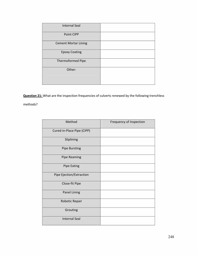
248
Internal Seal
Point CIPP
Cement Mortar Lining
Epoxy Coating
Thermoformed Pipe
Other:
Question 21: What are the inspection frequencies of culverts renewed by the following trenchless
methods?
Method Frequency of Inspection
Cured‐in‐Place Pipe (CIPP)
Sliplining
Pipe Bursting
Pipe Reaming
Pipe Eating
Pipe Ejection/Extraction
Close‐fit Pipe
Panel Lining
Robotic Repair
Grouting
Internal Seal

249
Point CIPP
Cement Mortar Lining
Epoxy Coating
Thermoformed Pipe
Other:
Question 22: What are the important factors which influence the decision making procedure on
whether to employ an open‐cut (traditional) replacement or to use trenchless renewal methods?
Factor Considered?
Location Yes No
Traffic Volume Yes No
Detour Availability Yes No
Depth of Cover Yes No
Other:
Yes No

250
Appendix 2: Industry Survey Form

251
Use of Trenchless Technologies for a Comprehensive Asset Management of
Culverts and Drainage Infrastructures
SURVEY FORM
Part 1 Contact Information
Part 2 Culvert Asset Management Definition of Culvert:
A structure of less than 6.1-m (20-ft) span as measured along the road centerline which is used as an underground drainage system for highways is classified as a culvert.
Question 1: Does your company work on Culvert? (Yes/No) If yes, continue with the survey, if NO, Thank You for your time.
Question 2: Does your company provide Culvert Inspection Services? (Yes/No) Question 3: Does your company have or use any Standard Inspection Guidelines? (Yes/No) If yes, please provide what standard you use Question 4: Rank the major problems responsible for failure of culverts. (Rank "1" for the factor which affects more and "8" to the problem which affects the least for the problems listed below).

252
*The definitions of all the factors are explained in the Glossary section in the end of the form
Question 5: Rank the Culvert Materials which your company renews more in descending order. (Number "1" for culvert which is renewed most to Number "4" which your company has renewed least). If the material is not listed in the Drop down list then choose "other" and specify the material outside the table in the space given.
Part 3 Culvert Construction, Repair, Renovation, Replacement (Renewal) and Usage of Trenchless Technologies
Question 6: Check the boxes for the Trenchless Renewal Methods which your company carry out? How many installations do your company carry out do every year?
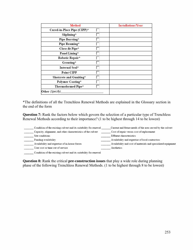
253
*The definitions of all the Trenchless Renewal Methods are explained in the Glossary section in the end of the form
Question 7: Rank the factors below which govern the selection of a particular type of Trenchless Renewal Methods according to their importance? (1 to be highest through 14 to be lowest)
Question 8: Rank the critical pre-construction issues that play a wide role during planning phase of the following Trenchless Renewal Methods. (1 to be highest through 8 to be lowest)
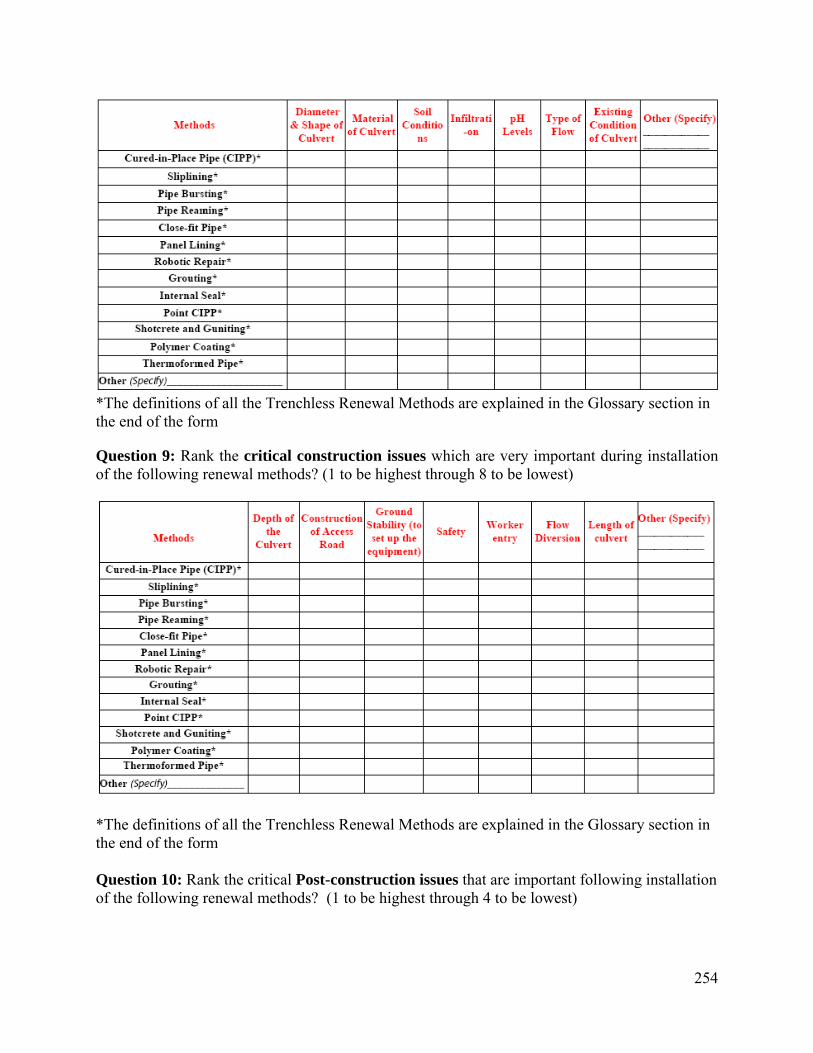
254
*The definitions of all the Trenchless Renewal Methods are explained in the Glossary section in the end of the form
Question 9: Rank the critical construction issues which are very important during installation of the following renewal methods? (1 to be highest through 8 to be lowest)
*The definitions of all the Trenchless Renewal Methods are explained in the Glossary section in the end of the form Question 10: Rank the critical Post-construction issues that are important following installation of the following renewal methods? (1 to be highest through 4 to be lowest)

255
*The definitions of all the Trenchless Renewal Methods are explained in the Glossary section in the end of the form
Question 11: What are the important factors in order to decide on whether to do an open-cut (traditional) replacement or to use trenchless renewal methods?
Question 12: Provide the minimum and maximum culverts sizes your company has employed for the following Trenchless Renewal Methods in inches. Also specify the Maximum size of the culvert that you think can be installed by the following methods.
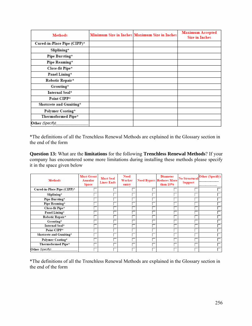
256
*The definitions of all the Trenchless Renewal Methods are explained in the Glossary section in the end of the form Question 13: What are the limitations for the following Trenchless Renewal Methods? If your company has encountered some more limitations during installing these methods please specify it in the space given below
*The definitions of all the Trenchless Renewal Methods are explained in the Glossary section in the end of the form
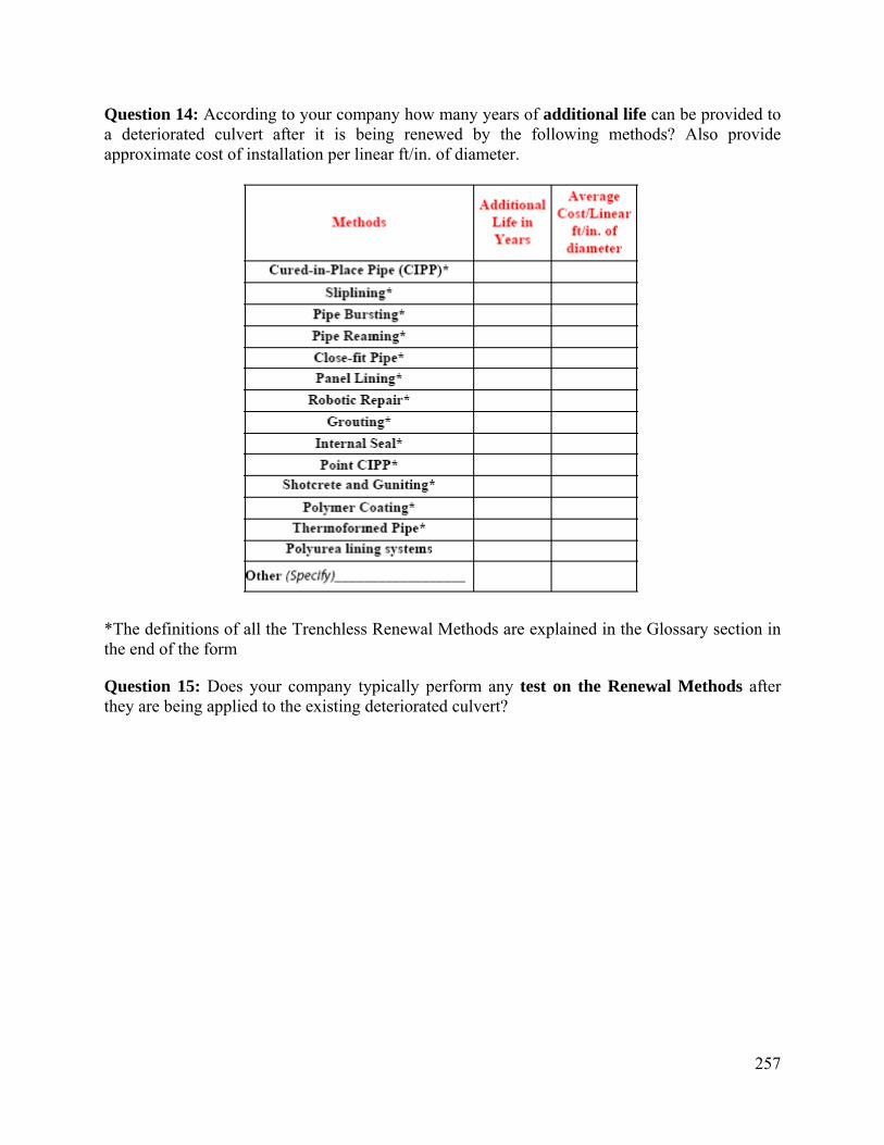
257
Question 14: According to your company how many years of additional life can be provided to a deteriorated culvert after it is being renewed by the following methods? Also provide approximate cost of installation per linear ft/in. of diameter.
*The definitions of all the Trenchless Renewal Methods are explained in the Glossary section in the end of the form
Question 15: Does your company typically perform any test on the Renewal Methods after they are being applied to the existing deteriorated culvert?
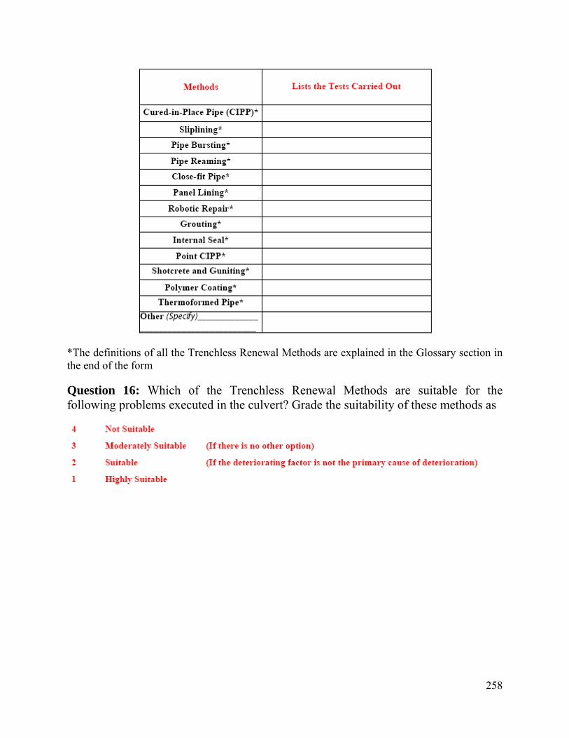
258
*The definitions of all the Trenchless Renewal Methods are explained in the Glossary section in the end of the form
Question 16: Which of the Trenchless Renewal Methods are suitable for the following problems executed in the culvert? Grade the suitability of these methods as

259
*The definitions of all the Trenchless Renewal Methods are explained in the Glossary section in the end of the form
Question 17: Is there any relation between the existing culvert material and the New Trenchless Renewal Method to be used? For e.g. suppose Cured In Place Pipe is best solution if the existing culvert is a concrete culvert. If yes specify the relation in terms of :

260
*The definitions of all the Trenchless Renewal Methods are explained in the Glossary section in the end of the form
Question 18: What specification and material does your company use for Trenchless Renewal Methods specifically for culvert applications? Please provide us a copy.

261
*The definitions of all the Trenchless Renewal Methods are explained in the Glossary section in the end of the form
Question 19: Please use this space additional information to be considered in our study. Also please explain if your company uses any other type of Trenchless Technology.
Survey Glossary
Renewal Methods:
Cured in place pipe (CIPP): Lining system in which a thin flexible tube of polymer or glass fiber fabric is impregnated with thermoset resin and expanded by means of fluid pressure into position on the inner wall of a defective pipeline before curing the resin to harden the material. The uncured material may be installed by winch or inverted by water or air pressure.
Pipe bursting: A pipe replacement for breaking the existing pipe by brittle fracture, using force from within, applied mechanically, the remains being forced into the surrounding ground. At the same time a new pipe, of the same or larger diameter, is drawn in behind the bursting tool. The pipe bursting device may be based on an impact molding tool to exert diverted forward thrust to the radial bursting effect required, or by a hydraulic device inserted into the pipe and expanded to erect direct radial force or a static hammer. For a new pipe, generally a HDPE pipe is used, but currently PVC, ductile iron, clay, and GRP is also used. Also know as pipe cracking and pipe splitting.
Pipe Reaming: A variation of directional boring called pipe reaming can be used to replace existing clay, asbestos cement, non-reinforced concrete and PVC pipe. A reamer is pulled through the existing pipe which cuts the pipe into small pieces. The pipe pieces are flushed out the bore hole with the drilling fluid.
Close Fit Pipe: Description of a lining system in which the new pipe makes close contact with the existing defective pipe at normal or minimum diameter.
Panel Lining: Panel Lining is a Modified Sliplining Method. The shape of the culvert is covered by preparing panels and fitting them to the culvert. It can be used to structurally renew large diameter pipes. This method can accommodate different shapes.
Robotic Repairs: One of the new Trenchless Technologies. It comprises of a grinding robot and a filler robot. The former removes intrusions, and also mills out cracks to provide a good surface, the filler robot applies an epoxy.
Grouting: 1. Filling of annular space between the host pipe and the carrier pipe. Grouting is also used to fill the spaces around laterals and between the new pipe and manholes. Other uses of grouting are for localized repairs of defective pipes and ground improvement prior to excavation
262
during new installations. 2. The process of filling voids, or modifying or improving ground conditions. Grouting materials may be cementitious, chemical, or other mixtures. In trenchless technology, grouting may be used for filling voids around the pipe or shaft, or for improving ground conditions. 3. A method of filling voids with cementitious or polymer grout. Internal Seal: A structural repair method in which basically a new pipe is inserted or cured within the old one.
Sliplining: The process of placing a smaller diameter pipe in a larger diameter existing pipe to improve the culvert structure and repair leaks. The annular space between the pipes is usually filled with grout
Shotcrete and Guniting: Sprayed concrete has terms such as shotcreting and guniting. The two last terms are quite similar however it is believed that guniting is more the spraying of concrete with an aggregate size less than 10mm.
Point CIPP: CIPP techniques entail impregnating fabric with a suitable resin, pulling this into place within the sewer around an inflatable packer or mandrel, and then filling the packer with water, steam, or air under pressure to press the patch against the existing sewer wall while the resin cures.
Polymer Coating: It is a thermoset coating made up of inert plastic like Epoxies, Urethanes and Ureas, Polyesters which have a high resistance to corrosion, they are applied by trained professionals using special spraying equipments and as per the manufactures specifications.
Spiral Wound (Grout): In this process a new pipe is installed inside the existing pipe from the continuous strip of polyvinyl chloride (PVC). The strip has tongue and groove casting on its edges. It is fed to a special winding machine placed in a manhole, which creates a continuous helically wound liner that proceeds through the existing pipe. The continuous spiral joint is watertight. Upon completions of the annulus space between the lining and the existing pipe wall is usually required.
Spiral Wound (Ungrout): It is the same process of laying spiral strip as in above Spiral Wound (Grout), but if the lining pipe is closely fitted then there is no need of grouting.
Thermoformed Pipe: A type of renewal method which uses poly vinyl chloride (PVC) or polyethylene (PE) pipe that is expanded by thermoforming to fit tightly to fit inside the host pipe.
Internal Seal: Internal Seals are used for structural repair pipe joints and missing pipe sections. It can be used in both worker entry and non worker entry pipes.
Other Definitions:
Abrasion: Abrasion is the gradual wearing away of the culvert wall due to the impingement of bed load and suspended material.
Corrosion: It is a deterioration or dissolution of a material by a chemical or electrochemical reaction with its environment

263
Cracking: A fissure in an installed precast concrete culvert . Corrosion: It is a deterioration or dissolution of a material by a chemical or electrochemical reaction with its environment.
Debris: Any material including floating woody materials and other trash, suspended sediment, or bed load moved by a flowing stream.
Deflection: Change in the bending radius due to stress, temperature, time and other factors.
Discharge (Q): Flow from a culvert, sewer or channel in CFS.
Efflorescence: Efflorescence is a combination of calcium carbonate leached out of the cement paste and other recrystallized carbonate and chloride compounds. It is a white crystalline or powdery deposit on the surface of the concrete surface and is caused by water seeping through the culvert wall. The water dissolves salts inside the concrete surface, while moving through it, and then evaporates leaving the salts on the surface
Erosion (Culvert): Wearing o grinding away of culvert material by water laden with sand, gravel or stones; generally referred to as abrasion
Joint failure: Failures which occur in the joints due to uneven bedding, poorly compacted backfilling operations, or unexpected settlements.
Hydraulic capacity: Failure occurring due to insufficient capacity or flooding.
pH Value : The log of the reciprocal of the hydrogen ion concentration of a solution. The pH value of 7.0 is neutral; values of less than 7.0 are acid; values of more than 7.0 are acidic.
Point repairs: Repair works on an existing pipe, to an extent less than the run between two access points or manholes.
Repair: Reconstruction of short pipe lengths, but not the reconstruction of the whole pipe line. Therefore a new design life is not provided. In contrast, in pipe line renewal, a new design life is provided to existing pipeline system.
Replacement: All aspects of upgrading with a new design life for the performance of the existing pipeline. Includes rehabilitation and renovation.
Spiral lining: A technique in which a ribbed plastic strip is spirally wound by a winding machine to form liner, which is inserted into a defective pipeline. The annular space may be grouted or the spiral liner expanded to reduce the annulus and form a close fit liner. In larger diameters, the strips are sometimes formed into panel and installed by handful stuff. Grouting the annular space after installation is recommended.
Trenchless Rehabilitation: It is the process of Upgrading to a new design life by forming a new pipe within the existing pipe with minimum or no excavation.

264
Trenchless methods: Also no-dig techniques for underground pipeline and utility construction and replacement, rehabilitation, renovation (collectively called renewal), repair, inspection, leak direction, and so on, with minimum r no excavation from the ground surface.
Utility tunneling: It is general approach of constructing underground utility line by removing the excavated soil from the front of cutting face and installing liner segments to form continuous ground support structures. The product pipe is then transported and installed inside the tunnel. The annular space between the liner and the pipe is usually filled with grout.

265
Appendix 3: Form CR-87 and CR-86
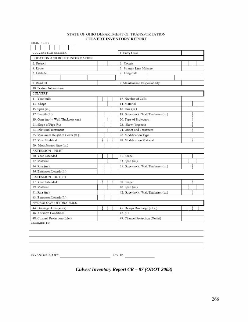
266
Culvert Inventory Report CR – 87 (ODOT 2003)

267
Culvert Inspection Report CR – 86 (ODOT 2003)