Embed Size (px)
Citation preview
8/20/2019 Use of Shainin Design of Experiments to Reduce the Tripping Force of an Air Circuit Breaker
http://slidepdf.com/reader/full/use-of-shainin-design-of-experiments-to-reduce-the-tripping-force-of-an-air 1/8
The International Journal Of Engineering And Science (IJES) || Volume || 4 || Issue || 11 || Pages || PP -11-18|| 2015 ||ISSN (e): 2319 – 1813 ISSN (p): 2319 – 1805
www.theijes.com The IJES Page 11
Use of Shainin Design of Experiments to Reduce the Tripping
Force of an Air Circuit Breaker
1Anuj Ghurka,
2 Nilesh Pawar
1 Department of Production Engineering, V.J.T.I.
2Quality Control & Reliability, L&T
--------------------- --------------------------- ---------- ABSTRACT----------------------------------- ------------- ------------
This paper essentially deals with lowering the tripping force in an Air Circuit Breaker (ACB) to desired levels.
Cases of high tripping force (HTF) were reported during the assembly which led to rejection or rework of
breakers at assembly level. The components in the breaker contributing to HTF were determined by Component
Search technique of Shainin Design of Experiments (DOE). It was found out that Trip D Shaft and Roller Trip
Link (RTL) were important components contributing to high tripping force. The changes were implemented and
these were effective in bringing down the tripping force within desired limits.
Keywords - Air Circuit Breaker (ACB), High Tripping Force (HTF), Roller Trip Link (RTL), Shainin Design of Experiments (DOE), Trip D Shaft.
----------------------------------------------------------------------------------------------------------------------------- ----------
Date of Submission: 19 October 2015 Date of Accepted: 03 October 2015
-------------------------------------------------------------------------------------------------------------------------------- --------
I. IntroductionAn air circuit breaker is switchgear, which works as switching and current interrupting device. Under
normal continuous current rating, a circuit breaker is a single switching device. When the current is above the
normal rating, either on overload or short circuit current, the circuit breaker is an automatic over-current
protective device.
The function of protecting the device is relatively complex, as the fault currents are relatively high and
should be interrupted within very short time viz. within a few seconds. The fault current can damage theequipment if allowed to fall for a longer duration. The mechanism, which is the heart of the circuit braker, musttrip within a specific range of forces. If it trips at a force above the maximum set tripping force, it leads to the
rejection of the breaker at the quality inspection stage because of HTF. In this project the root causes of HTF are
determined by application of Component Search technique of Shainin DOE.
II. Literature ReviewAn alternative to the Classical and Taguchi experimental design is the lesser known but much simpler
Shainin Design of Experiments (DOE) approach developed and perfected by Dorian Shainin [1] . Shainin‟s
philosophy has been, “Don‟t let the engineers do the guessing; let the parts do the talking.” Shainin recognized
the value of empirical data in solving realworld problems. In Motorola‟s phenomenal success with six sigma
approach, Shainin techniques played a pivotal role. According to Bhote [2], “Motorola‟s plants, suppliers, and
customers all over the globe conducted about hundreds of Shainin experiments as part of their Six Sigma quality
movement.”Shainin techniques are highly effective in determining the root cause and validating it. It does not require
any statistical software to analyse the results. Moreover, it does not even require knowledge of difficult
statistical tools. Shainin developed techniques [3][4][5][6][7][8] to track down the dominant source through a
process of elimination [8], called progressive search. Thomas and Anthony [11] have successfully employed
Shainin techniques in identifying the influencing variables that control the joint strength of honeycomb
composite tongue and slot joints within an organization. The results of the study provided the stimulus for the
wider application of this approach inother business processes within the company. Desai and Jugulkar [10] used
Shainin DOE to identify the root causes of engine rejection in assembly and also for tappet setting defects in a
water cooled engine at in process verification.
Shainin method called “Component Search” has been found to be quite popular among engineers.
Component search is one of the clue generation techniques in a DOE study. It is applicable where there are unit
to unit variations. With the help of component search, a large number of possible causes of variation can bereduced to a family of dominant causes or the dominant cause itself. This method is used when the product can
be disassembled and assembled with relative ease and with no change or damage to the subassemblies and
8/20/2019 Use of Shainin Design of Experiments to Reduce the Tripping Force of an Air Circuit Breaker
http://slidepdf.com/reader/full/use-of-shainin-design-of-experiments-to-reduce-the-tripping-force-of-an-air 2/8
Use of Shainin Design of Experiments…
www.theijes.com The IJES Page 12
components. This method is suitable for an assembled product to find out whether the defect in the product is
due to the assembly process or one of its constituent parts [11]. Component search, being an offline technique,
does not hinder with the regular production.
Shanmugam and Kalaichelvan [11], in order to reduce the rejection & re-work, conducted a study to analyze
the rejection using Shainin component search technique for assembly process. It indicated that two of the sub
assembly components were the root causes for the rejection. This helped in improving the knowledge base ofthe manufacturing and assembly process and also helped narrowing down to the root cause or a number of root
causes in short span of time. Reddy, Varadarajan and Prasad [12] employed Shainin component search
successfully at Bosch Ltd, Banglore to deal with quality issues. They concluded that Shainin technique was
simple and a strong statistical tool to handle problems during manufacturing of components.The purpose of this project to determine the root causes of HTF in Air Circuit Breakers. Approximately 14
% rejection was obtained in the breakers because of HTF in the quality inspection stage, which in turn led to,
Around 30-35 minutes of re-work time per breaker to replace mechanism.
Around Rs 1100 per hour Labor cost for each Re-work.
Loss of Manufacturing Lead time due to high re-works.
Cost of new components which are replaced in HTF mechanism.
Thus, there was a need to minimize the rejections in the breakers which could only be done by finding out
the cause/s behind the HTF in the breaker and then take necessary steps to obtain it within the set limt of 1.1
Kgf.
III. MethodologyInitially one pair of Best of Best (BOB) and Worst of Worst (WOW) products is chosen for analysis. To
narrow down to the dominant cause, we carry out the process of assembling and disassembling and alsoswapping the components between BOB and WOW. They are disassembled and reassembled twice to find out
whether good remains good and bad remains bad consistently, through D/d test ( D= Difference between
median of BOB and WOW ; d = Average of the ranges of BOB and WOW ). It is preferable to have a
measurable response to do this D/d test. If the D/d ratio is greater than 1.25, it means the assembly process is
consistent and the defect in the product is due to one of its constituent parts [13]. It is also important to set updecision limits for BOB and WOW using the formula:
Decision limits (BOB) = Median (BOB) +/- 2.776d/1.81 …..(1)
Decision limits (WOW) = Median (WOW) +/- 2.776d/1.81 …..(2)
After the components have been identified, a capping run is carried out to check whether the rest of the
components can be eliminated and if there are still important components to be identified other than the
originally identified components.
During the course of experiment it must be ensured that the assemblies are done as per Shop Standard
Operating Procedure (SOP) and Assembly Instruction Sheet, at every stage.
IV. Research Models and Reporting
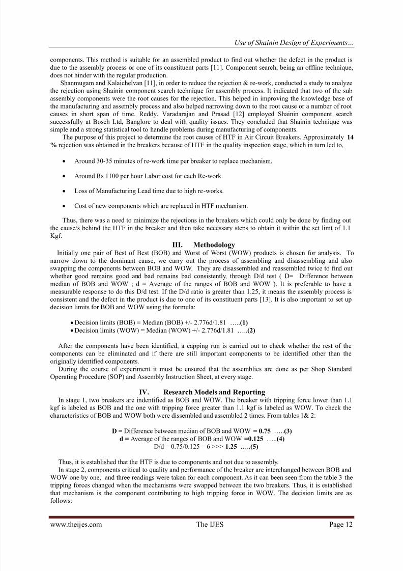
In stage 1, two breakers are indentified as BOB and WOW. The breaker with tripping force lower than 1.1kgf is labeled as BOB and the one with tripping force greater than 1.1 kgf is labeled as WOW. To check the
characteristics of BOB and WOW both were dissembled and assembled 2 times. From tables 1& 2:
D = Difference between median of BOB and WOW = 0.75 …..(3)
d = Average of the ranges of BOB and WOW =0.125 …..(4)
D/d = 0.75/0.125 = 6 >>> 1.25 …..(5)
Thus, it is established that the HTF is due to components and not due to assembly.
In stage 2, components critical to quality and performance of the breaker are interchanged between BOB and
WOW one by one, and three readings were taken for each component. As it can been seen from the table 3 the
tripping forces changed when the mechanisms were swapped between the two breakers. Thus, it is established
that mechanism is the component contributing to high tripping force in WOW. The decision limits are as
follows:
8/20/2019 Use of Shainin Design of Experiments to Reduce the Tripping Force of an Air Circuit Breaker
http://slidepdf.com/reader/full/use-of-shainin-design-of-experiments-to-reduce-the-tripping-force-of-an-air 3/8
Use of Shainin Design of Experiments…
www.theijes.com The IJES Page 13
a. BOB = Median (BOB) +/- 2.776d/1.81 = 0.758 to 1.141 …..(6)
b. WOW = Median (WOW) +/- 2.776d/1.81 = 1.308 to 1.692 …..(7)
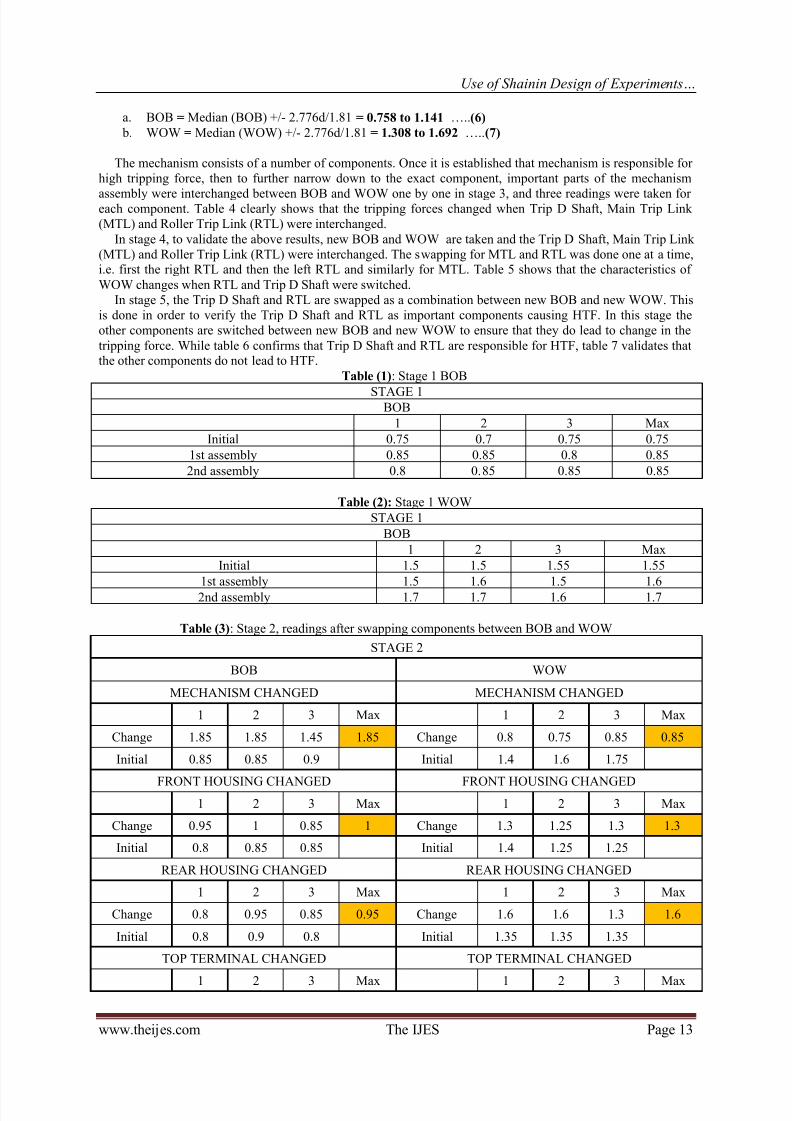
The mechanism consists of a number of components. Once it is established that mechanism is responsible for
high tripping force, then to further narrow down to the exact component, important parts of the mechanism
assembly were interchanged between BOB and WOW one by one in stage 3, and three readings were taken foreach component. Table 4 clearly shows that the tripping forces changed when Trip D Shaft, Main Trip Link
(MTL) and Roller Trip Link (RTL) were interchanged.
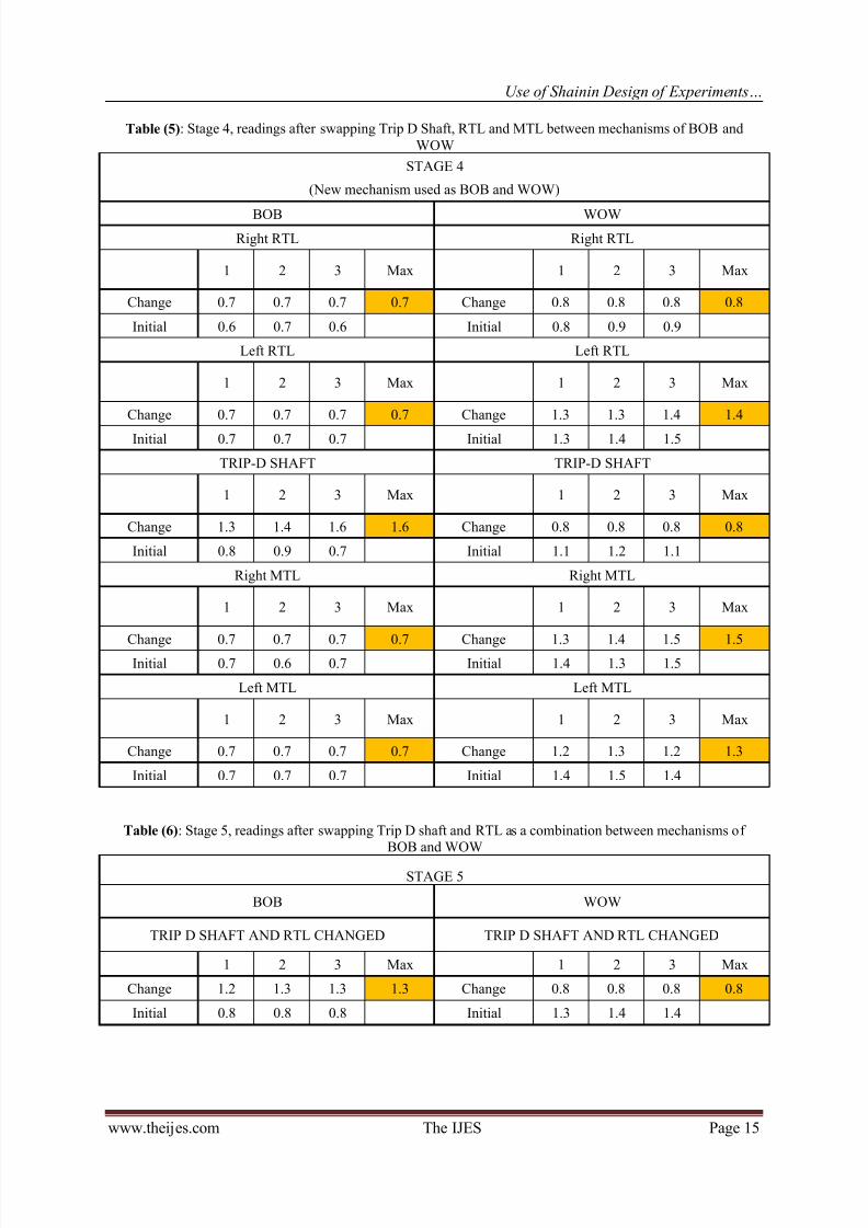
In stage 4, to validate the above results, new BOB and WOW are taken and the Trip D Shaft, Main Trip Link
(MTL) and Roller Trip Link (RTL) were interchanged. The swapping for MTL and RTL was done one at a time,i.e. first the right RTL and then the left RTL and similarly for MTL. Table 5 shows that the characteristics of
WOW changes when RTL and Trip D Shaft were switched.
In stage 5, the Trip D Shaft and RTL are swapped as a combination between new BOB and new WOW. This
is done in order to verify the Trip D Shaft and RTL as important components causing HTF. In this stage the
other components are switched between new BOB and new WOW to ensure that they do lead to change in the
tripping force. While table 6 confirms that Trip D Shaft and RTL are responsible for HTF, table 7 validates thatthe other components do not lead to HTF.
Table (1): Stage 1 BOB
STAGE 1BOB
1 2 3 Max
Initial 0.75 0.7 0.75 0.75
1st assembly 0.85 0.85 0.8 0.85
2nd assembly 0.8 0.85 0.85 0.85
Table (2): Stage 1 WOW
STAGE 1
BOB
1 2 3 Max
Initial 1.5 1.5 1.55 1.55
1st assembly 1.5 1.6 1.5 1.6
2nd assembly 1.7 1.7 1.6 1.7
Table (3): Stage 2, readings after swapping components between BOB and WOW
STAGE 2
BOB WOW
MECHANISM CHANGED MECHANISM CHANGED
1 2 3 Max 1 2 3 Max
Change 1.85 1.85 1.45 1.85 Change 0.8 0.75 0.85 0.85
Initial 0.85 0.85 0.9 Initial 1.4 1.6 1.75
FRONT HOUSING CHANGED FRONT HOUSING CHANGED1 2 3 Max 1 2 3 Max
Change 0.95 1 0.85 1 Change 1.3 1.25 1.3 1.3
Initial 0.8 0.85 0.85 Initial 1.4 1.25 1.25
REAR HOUSING CHANGED REAR HOUSING CHANGED
1 2 3 Max 1 2 3 Max
Change 0.8 0.95 0.85 0.95 Change 1.6 1.6 1.3 1.6
Initial 0.8 0.9 0.8 Initial 1.35 1.35 1.35
TOP TERMINAL CHANGED TOP TERMINAL CHANGED
1 2 3 Max 1 2 3 Max
8/20/2019 Use of Shainin Design of Experiments to Reduce the Tripping Force of an Air Circuit Breaker
http://slidepdf.com/reader/full/use-of-shainin-design-of-experiments-to-reduce-the-tripping-force-of-an-air 4/8
Use of Shainin Design of Experiments…
www.theijes.com The IJES Page 14
Change 0.95 0.9 0.8 0.95 Change 1.4 1.5 1.4 1.5
Initial 0.9 0.95 0.9 Initial 1.55 1.4 1.5
BOTTOM TERMINAL CHANGED BOTTOM TERMINAL CHANGED
1 2 3 Max 1 2 3 Max
Change 0.7 0.8 0.9 0.9 Change 1.85 1.8 1.65 1.85
Initial 0.8 0.85 0.75 Initial 1.4 1.45 1.2
Table (4): Stage 3, readings after swapping components between mechanisms of BOB and WOW
STAGE 3
BOB WOW
POLE SHAFT WITH RETURN SPRING POLE SHAFT WITH RETURN SPRING
1 2 3 Max 1 2 3 MaxChange 0.8 0.8 0.85 0.85 Change 1.25 1.2 1.2 1.25
Initial 0.9 0.95 0.9 Initial 1.2 1.2 1.25
SIDE PLATE SIDE PLATE
1 2 3 Max 1 2 3 Max
Change 0.9 0.95 0.95 0.95 Change 1.3 1.3 1.35 1.35
Initial 0.85 0.8 0.8 Initial 1.25 1.3 1.3
MAIN SPRING MAIN SPRING
1 2 3 Max 1 2 3 Max
Change 0.9 0.95 0.85 0.95 Change 1.35 1.2 1.2 1.35Initial 0.75 0.85 0.75 Initial 1.2 1.3 1.5
RTL RTL
1 2 3 Max 1 2 3 Max
Change 1.3 1.3 1.3 1.3 Change 0.75 0.85 0.9 0.9
Initial 0.95 0.75 0.95 Initial 1.25 1.35 1.4
TRIP-D SHAFT TRIP-D SHAFT
1 2 3 Max 1 2 3 Max
Change 1.2 1.5 1.25 1.5 Change 0.85 0.95 0.85 0.95
Initial 0.85 0.95 0.85 Initial 1.2 1.5 1.25
MTL MTL
1 2 3 Max 1 2 3 Max
Change 0.8 0.75 0.7 0.8 Change 0.75 0.75 0.75 0.75
Initial 0.7 0.7 0.7 Initial 0.7 0.7 0.7
CHARGING SYSTEM CHARGING SYSTEM
1 2 3 Max 1 2 3 Max
Change 0.7 0.65 0.75 0.75 Change 1.3 1.25 1.45 1.45
Initial 0.75 0.75 0.75 Initial 1.35 1.2 1.4
8/20/2019 Use of Shainin Design of Experiments to Reduce the Tripping Force of an Air Circuit Breaker
http://slidepdf.com/reader/full/use-of-shainin-design-of-experiments-to-reduce-the-tripping-force-of-an-air 5/8
Use of Shainin Design of Experiments…
www.theijes.com The IJES Page 15
Table (5): Stage 4, readings after swapping Trip D Shaft, RTL and MTL between mechanisms of BOB and
WOW
STAGE 4
(New mechanism used as BOB and WOW)
BOB WOW
Right RTL Right RTL
1 2 3 Max 1 2 3 Max
Change 0.7 0.7 0.7 0.7 Change 0.8 0.8 0.8 0.8
Initial 0.6 0.7 0.6 Initial 0.8 0.9 0.9
Left RTL Left RTL
1 2 3 Max 1 2 3 Max
Change 0.7 0.7 0.7 0.7 Change 1.3 1.3 1.4 1.4
Initial 0.7 0.7 0.7 Initial 1.3 1.4 1.5
TRIP-D SHAFT TRIP-D SHAFT
1 2 3 Max 1 2 3 Max
Change 1.3 1.4 1.6 1.6 Change 0.8 0.8 0.8 0.8
Initial 0.8 0.9 0.7 Initial 1.1 1.2 1.1
Right MTL Right MTL
1 2 3 Max 1 2 3 Max
Change 0.7 0.7 0.7 0.7 Change 1.3 1.4 1.5 1.5Initial 0.7 0.6 0.7 Initial 1.4 1.3 1.5
Left MTL Left MTL
1 2 3 Max 1 2 3 Max
Change 0.7 0.7 0.7 0.7 Change 1.2 1.3 1.2 1.3
Initial 0.7 0.7 0.7 Initial 1.4 1.5 1.4
Table (6): Stage 5, readings after swapping Trip D shaft and RTL as a combination between mechanisms ofBOB and WOW
STAGE 5
BOB WOW
TRIP D SHAFT AND RTL CHANGED TRIP D SHAFT AND RTL CHANGED
1 2 3 Max 1 2 3 Max
Change 1.2 1.3 1.3 1.3 Change 0.8 0.8 0.8 0.8
Initial 0.8 0.8 0.8 Initial 1.3 1.4 1.4
8/20/2019 Use of Shainin Design of Experiments to Reduce the Tripping Force of an Air Circuit Breaker
http://slidepdf.com/reader/full/use-of-shainin-design-of-experiments-to-reduce-the-tripping-force-of-an-air 6/8
Use of Shainin Design of Experiments…
www.theijes.com The IJES Page 16
Table (7): Stage 5, readings for the validation of unimportant components of BOB and WOW
STAGE 5
NEW BOB NEW WOW
Remaining Components Remaining Components
1 2 3 Max 1 2 3 Max
Change 0.7 0.7 0.7 0.7 Change 1.2 1.3 1.3 1.25
Initial 0.7 0.7 0.7 Initial 1.3 1.3 1.3
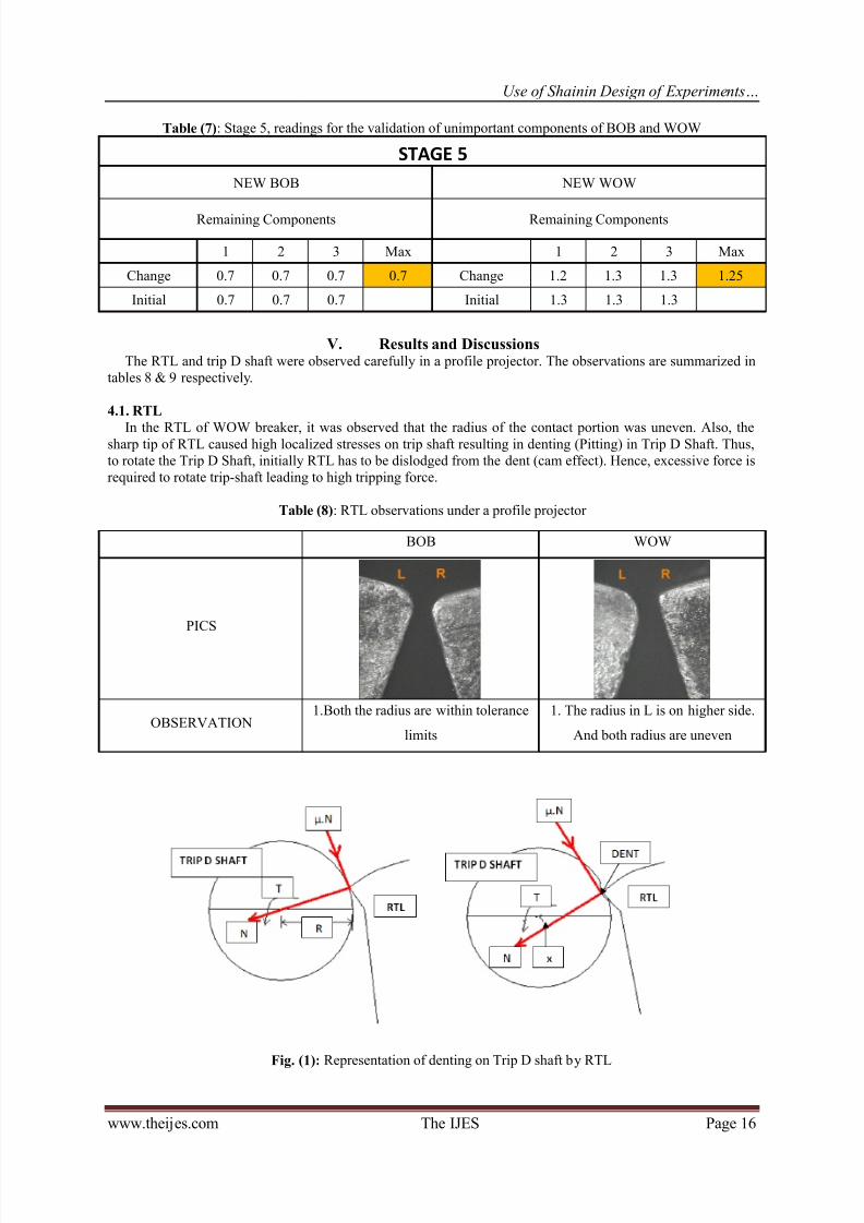
V. Results and DiscussionsThe RTL and trip D shaft were observed carefully in a profile projector. The observations are summarized in
tables 8 & 9 respectively.
4.1. RTL
In the RTL of WOW breaker, it was observed that the radius of the contact portion was uneven. Also, thesharp tip of RTL caused high localized stresses on trip shaft resulting in denting (Pitting) in Trip D Shaft. Thus,
to rotate the Trip D Shaft, initially RTL has to be dislodged from the dent (cam effect). Hence, excessive force is
required to rotate trip-shaft leading to high tripping force.
Table (8): RTL observations under a profile projector
Fig. (1): Representation of denting on Trip D shaft by RTL
BOB WOW
PICS
OBSERVATION1.Both the radius are within tolerance
limits
1. The radius in L is on higher side.
And both radius are uneven
8/20/2019 Use of Shainin Design of Experiments to Reduce the Tripping Force of an Air Circuit Breaker
http://slidepdf.com/reader/full/use-of-shainin-design-of-experiments-to-reduce-the-tripping-force-of-an-air 7/8
Use of Shainin Design of Experiments…
www.theijes.com The IJES Page 17
OK condition: Torque required to rotate Trip-D-shaft= T= µ.N.R …..(8)
Not OK condition: Torque required to rotate Trip-D-shaft= T‟= µ.N.R‟ + (N.x) …..(9)
N.x= Undesired increase in torque which leads to increase in Trip force.
If there is dent on trip-d shaft the additional torque will required for lift the RTL from dent, so effective
torque on trip-d shaft with dent will be calculated as follows:
Calculations – Torque on Trip-d shaft: µ*R*N …..(10)
Torque on Trip-d shaft with dent (T): µ* R‟*N‟+ (x*N‟) …..(11)
% increase in Torque on Trip-d shaft, considering dent =76.3%
% increase in Trip Force, considering dent = 44.60%
To prevent this dent formation, radius at the contact end was slightly increased.
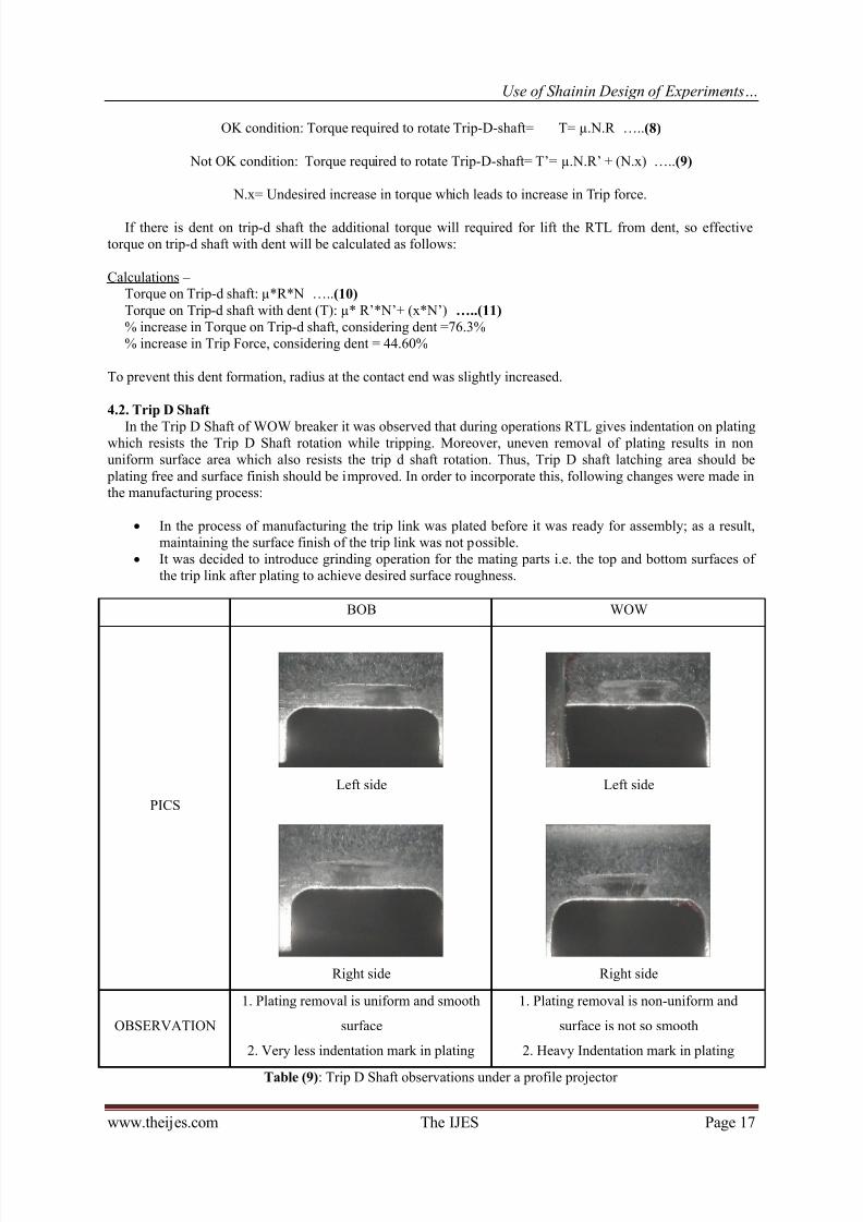
4.2. Trip D Shaft
In the Trip D Shaft of WOW breaker it was observed that during operations RTL gives indentation on platingwhich resists the Trip D Shaft rotation while tripping. Moreover, uneven removal of plating results in non
uniform surface area which also resists the trip d shaft rotation. Thus, Trip D shaft latching area should be
plating free and surface finish should be improved. In order to incorporate this, following changes were made inthe manufacturing process:
In the process of manufacturing the trip link was plated before it was ready for assembly; as a result,
maintaining the surface finish of the trip link was not possible.
It was decided to introduce grinding operation for the mating parts i.e. the top and bottom surfaces of
the trip link after plating to achieve desired surface roughness.
Table (9): Trip D Shaft observations under a profile projector
BOB WOW
PICS
Left side
Right side
Left side
Right side
OBSERVATION
1. Plating removal is uniform and smooth
surface
2. Very less indentation mark in plating
1. Plating removal is non-uniform and
surface is not so smooth
2. Heavy Indentation mark in plating
8/20/2019 Use of Shainin Design of Experiments to Reduce the Tripping Force of an Air Circuit Breaker
http://slidepdf.com/reader/full/use-of-shainin-design-of-experiments-to-reduce-the-tripping-force-of-an-air 8/8
Use of Shainin Design of Experiments…
www.theijes.com The IJES Page 18
VI. ConclusionA Set of RTL & Trip D Shaft as per DOE result was made and tried out on 8 Rejected Breakers. Trip force
lowered down to 0.9 Kgf in all breakers. 40 Mechanisms with RTL & Trip D shaft made and handed over to
assembly shop for use in new breakers. All got cleared with average trip force of 0.7 Kgf. Set process for both
the components was implemented for regular production. 880 breakers were made with the DOE components,
the rejection percentage dropped down to 0.58% from 14.6%. The avoidance of rework helped the company to prevent expenditure of INR 2.1 million.
References[1] Bhote, K R and Bhote, A. K. (2000) World Class Quality, 2nd Edition. New York: American Management
Association.
[2] Nelson, L S (1991)„Review of World Class Quality- by K Bhote (1991)‟ Journal of Quality Technology, Vol. 25, pp. 152-153.
[3] Shainin, D. and Shainin, P. D. (1990) „Analysis of Experiments‟. 45th Annual Quality Congress Proceedings, ASQC, pp. 1071-1077.
[4] Shainin, P D (1992a) „Managing SPC -A Critical Quality System Element‟. 46th Annual Quality Congress Proceedings, ASQC,
pp. 251-257.[5] Shainin, P D (1993a). „Managing Quality Improvement‟. 47th Annual Quality Congress Proceedings, ASQC, pp. 554-560.
[6] Shainin, P D; Shainin, R D and Nelson, M T (1997). „Managing Statistical Engineering,” 51st Annual Quality Congress
Proceedings, ASQC, pp. 818-832.[7] Shainin, R D (1992b). „Technical Problem Solving Strategies, A Case Study,” 46th Annual Quality Congress Proceedings, ASQC,
pp. 876-882.[8] Shainin, R D (1993b). „Strategies for Technical Problem Solving,” Quality Engineering, Vol. 5, pp. 433-438.
[9] Andrew Thomas and Jiju Antony (2004), “Applying Shainin‟svariables searchmethodology inaerospace applications” Assembly
Automation, Vol. 24 Iss: 2, pp.184 - 191. Emerald Group Publishing Limited · ISSN 0144-5154.[10] Abhaysinh K. Desai, L. M. Jugulkar (2014), “Process Optimization By Using Shainin Six Sigma Tools And Techniques – A Case
Study In Manufacturing Industry”, International Journal of Mechanical And Production Engineering, ISSN: 2320-2092, Volume-
2, Issue- 4, pp. 58 – 63.[11] B. Shanmugam, K. Kalaichelvan (2014), “Rejection reduction of Vacuum Pump type Alternator Assembly”, IOSR Journal of
Mechanical and Civil Engineering (IOSR-JMCE), e- ISSN: 2278-1684, p-ISSN : 2320 – 334X, pp. 24-31.
[12] Nagaraja Reddy K M, Dr. Y S Varadarajan, Raghuveer Prasad (2014), “Quality Improvement during Camshaft KeywayTightening Using Shainin Approach”, International Journal of Scientific and Research Publications, ISSN: 2250-3153, Volume 4,
Issue 7, July 2014.
[13] K. Krishnaiah (2014), “Applied Statistical Quality Control and Improvement”, pp. 308-311.
Authors:
Anuj Ghurka is a graduate in Production Engineering from Veermata Jijabai Technological Institute, Mumbai.
Nilesh Pawar is Assistant Manager in the Quality Control and Reliability Department of Larsen &Toubro,Mumbai.


![HYUNDAI Miniature Series - Arian Niroo Circuit Breaker (MC… · [Icu] (kA r.m.s.) IEC60947-2 DC24V DC60V DC110V Ics (=% Icu) Tripping characteristic (curve) Electrical Durability](https://img.pdfslide.us/doc/110x75/5e9d8e8bb08f392c6b563569/hyundai-miniature-series-arian-circuit-breaker-mc-icu-ka-rms-iec60947-2.jpg)