Embed Size (px)
Citation preview
® SPECIF ICAT ION SUBMITTAL Page
Job Name:
Job Number:
Model Numbers:
LED Dimming Driver Hi-lumeT A-Series LTE Architectural Dimming
369543i 1 09.22.15
Hi-lumeT A-Series, case type K
3.00 in (76 mm) W x 1.00 in (25 mm) H x 4.90 in (124 mm) L
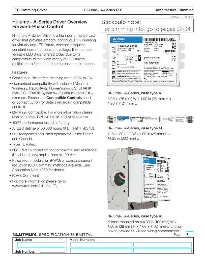
Hi-lumeT A-Series, case type M
1.18 in (30 mm) W x 1.00 in (25 mm) H x 14.25 in (362 mm) L
Hi-lumeT A-Series Driver Overview Forward-Phase Control
Hi-lumeT A-Series Driver is a high-performance LED driver that provides smooth, continuous 1% dimming for virtually any LED fixture, whether it requires constant-current or constant-voltage. It is the most versatile LED driver offered today due to its compatibility with a wide variety of LED arrays, multiple form factors, and numerous control options.
Features
• Continuous, flicker-free dimming from 100% to 1%.
• Guaranteed compatibility with selected Maestro Wireless®, RadioRA® 2, HomeWorks® QS, GRAFIK Eye® QS, GRAFIK Systems™, Quantum®, and C•L® dimmers. Please see Compatible Controls chart or contact Lutron for details regarding compatible controls.
• QwikFigTM compatible. For more information please refer to Lutron® P/N 041473 (K and M case only).
• 100% performance tested at factory.
• A rated lifetime of 50,000 hours @ tc =149 °F (65 °C).
• UL® recognized and listed options for United States and Canada.
• Type TL Rated.
• FCC Part 15 compliant for commercial and residential (UL® Listed only) applications at 120 V ~.
• Pulse width modulation (PWM) or constant-current reduction (CCR) dimming methods available. See Application Note #360 for details.
• RoHS Compliant
• For more information please go to: www.lutron.com/HilumeLED
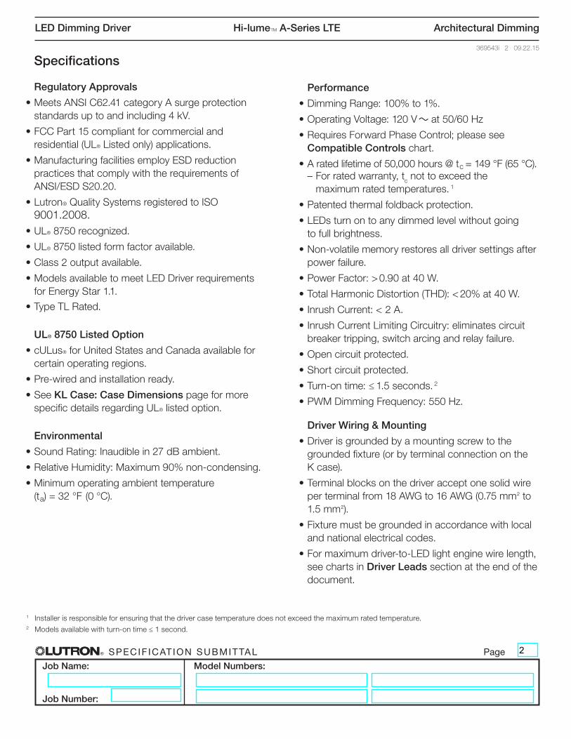
Hi-lumeT A-Series, case type KL
K-case mounted on a 4.00 in (102 mm) W x 1.50 in (38 mm) H x 4.00 in (102 mm) L junction box to provide UL® listed wiring compartment
1
Stickbulb note:For dimming info, go to pages 32-34
® SPECIF ICAT ION SUBMITTAL Page
Job Name:
Job Number:
Model Numbers:
LED Dimming Driver Hi-lumeT A-Series LTE Architectural Dimming
369543i 2 09.22.15
Specifications
Regulatory Approvals
• Meets ANSI C62.41 category A surge protection standards up to and including 4 kV.
• FCC Part 15 compliant for commercial and residential (UL® Listed only) applications.
• Manufacturing facilities employ ESD reduction practices that comply with the requirements of ANSI/ESD S20.20.
• Lutron® Quality Systems registered to ISO 9001.2008.
• UL® 8750 recognized.
• UL® 8750 listed form factor available.
• Class 2 output available.
• Models available to meet LED Driver requirements for Energy Star 1.1.
• Type TL Rated.
UL® 8750 Listed Option
• cULus® for United States and Canada available for certain operating regions.
• Pre-wired and installation ready.
• See KL Case: Case Dimensions page for more specific details regarding UL® listed option.
Environmental
• Sound Rating: Inaudible in 27 dB ambient.
• Relative Humidity: Maximum 90% non-condensing.
• Minimum operating ambient temperature (ta) = 32 °F (0 °C).
Performance
• Dimming Range: 100% to 1%.
• Operating Voltage: 120 V ~ at 50/60 Hz
• Requires Forward Phase Control; please see Compatible Controls chart.
• A rated lifetime of 50,000 hours @ tc = 149 °F (65 °C). – For rated warranty, tc not to exceed the
maximum rated temperatures. 1
• Patented thermal foldback protection.
• LEDs turn on to any dimmed level without going to full brightness.
• Non-volatile memory restores all driver settings after power failure.
• Power Factor: > 0.90 at 40 W.
• Total Harmonic Distortion (THD): < 20% at 40 W.
• Inrush Current: < 2 A.
• Inrush Current Limiting Circuitry: eliminates circuit breaker tripping, switch arcing and relay failure.
• Open circuit protected.
• Short circuit protected.
• Turn-on time: ≤ 1.5 seconds. 2
• PWM Dimming Frequency: 550 Hz.
Driver Wiring & Mounting
• Driver is grounded by a mounting screw to the grounded fixture (or by terminal connection on the K case).
• Terminal blocks on the driver accept one solid wire per terminal from 18 AWG to 16 AWG (0.75 mm( to 1.5 mm().
• Fixture must be grounded in accordance with local and national electrical codes.
• For maximum driver-to-LED light engine wire length, see charts in Driver Leads section at the end of the document.
1 Installer is responsible for ensuring that the driver case temperature does not exceed the maximum rated temperature.2 Models available with turn-on time ≤ 1 second.
2
® SPECIF ICAT ION SUBMITTAL Page
Job Name:
Job Number:
Model Numbers:
LED Dimming Driver Hi-lumeT A-Series LTE Architectural Dimming
369543i 3 09.22.15
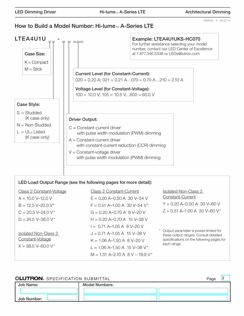
How to Build a Model Number: Hi-lumeT A-Series LTE
LTEA4U1U _ _ - _ _ _ _ _
Case Style:
S = Studded (K case only)
N = Non-Studded
L = UL® Listed (K case only)
Driver Output:
C = Constant-current driver with pulse width modulation (PWM) dimming
A = Constant-current driver with constant-current reduction (CCR) dimming
V = Constant-voltage driver with pulse width modulation (PWM) dimming
Current Level (for Constant-Current):020 = 0.20 A; 021 = 0.21 A…070 = 0.70 A…210 = 2.10 A
Voltage Level (for Constant-Voltage):100 = 10.0 V; 105 = 10.5 V…600 = 60.0 V
Case Size:
K = Compact
M = Stick
Example: LTEA4U1UKS-HC070For further assistance selecting your model number, contact our LED Center of Excellence at 1.877.346.5338 or [email protected]
Class 2 Constant-Voltage
A = 10.0 V–12.0 V
B = 12.5 V–20.0 V *
C = 20.5 V–24.0 V *
D = 24.5 V–38.0 V *
Isolated Non-Class 2 Constant-Voltage
X = 38.5 V–60.0 V *
Class 2 Constant-Current
E = 0.20 A–0.50 A 30 V–54 V
F = 0.51 A–1.00 A 30 V–54 V *
G = 0.20 A–0.70 A 8 V–20 V
H = 0.20 A–0.70 A 15 V–38 V
I = 0.71 A–1.05 A 8 V–20 V
J = 0.71 A–1.05 A 15 V–38 V
K = 1.06 A–1.50 A 8 V–20 V
L = 1.06 A–1.50 A 15 V–38 V *
M = 1.51 A–2.10 A 8 V – 19.9 V *
Isolated Non-Class 2 Constant-Current
Y = 0.20 A–0.50 A 30 V–60 V
Z = 0.51 A–1.00 A 30 V–60 V *
* Output parameter is power-limited for these output ranges. Consult detailed specifications on the following pages for each range.
LED Load Output Range (see the following pages for more detail):
3
® SPECIF ICAT ION SUBMITTAL Page
Job Name:
Job Number:
Model Numbers:
LED Dimming Driver Hi-lumeT A-Series LTE Architectural Dimming
369543i 4 09.22.15
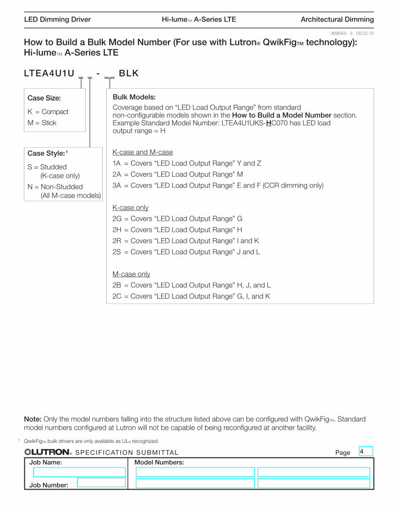
How to Build a Bulk Model Number (For use with Lutron® QwikFigTM technology): Hi-lumeT A-Series LTE
LTEA4U1U _ _ - _ _ BLK
Case Size:
K = Compact
M = Stick
K-case and M-case
1A = Covers “LED Load Output Range” Y and Z
2A = Covers “LED Load Output Range” M
3A = Covers “LED Load Output Range” E and F (CCR dimming only)
K-case only
2G = Covers “LED Load Output Range” G
2H = Covers “LED Load Output Range” H
2R = Covers “LED Load Output Range” I and K
2S = Covers “LED Load Output Range” J and L
M-case only
2B = Covers “LED Load Output Range” H, J, and L
2C = Covers “LED Load Output Range” G, I, and K
Bulk Models:Coverage based on “LED Load Output Range” from standard non-configurable models shown in the How to Build a Model Number section.Example Standard Model Number: LTEA4U1UKS-HC070 has LED load output range = H
Case Style: 1
S = Studded (K-case only)
N = Non-Studded (All M-case models)
1 QwikFigTM bulk drivers are only available as UL® recognized.
Note: Only the model numbers falling into the structure listed above can be configured with QwikFigTM. Standard model numbers configured at Lutron will not be capable of being reconfigured at another facility.
4
® SPECIF ICAT ION SUBMITTAL Page
Job Name:
Job Number:
Model Numbers:
LED Dimming Driver Hi-lumeT A-Series LTE Architectural Dimming
369543i 5 09.22.15
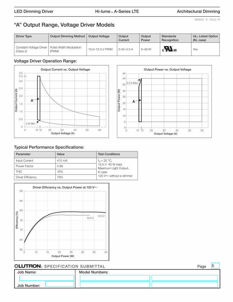
“A” Output Range, Voltage Driver Models
Voltage Driver Operation Range:
Typical Performance Specifications:
Output Current vs. Output Voltage
0
0.5
1
1.5
2
2.5
3
3.5
0 10 20 30 40 50 60
Output Voltage (V)
Out
put
Cur
rent
(A)
12
Output Power vs. Output Voltage
0
5
10
15
20
25
30
35
40
0 10 20 30 40 50 60
Output Voltage (V)
Out
put
Po
wer
(W)
12
60
65
70
75
80
85
90
5 10 15 20 25 30 35 40
Output Power (W)
Effi
cien
cy (%
)
Driver Efficiency vs. Output Power at 277 V~
A A
3.3
Parameter Value Test Conditions
Input Current 410 mA ta = 25 °C, 12.0 V 40 W load, Maximum Light Output, K case 120 V~ without a dimmer
Power Factor 0.98
THD 16%
Driver Efficiency 79%
Driver Type Output Dimming Method Output Voltage Output Current
Output Power
Standards Recognition
UL® Listed Option (KL case)
Constant-Voltage Driver (Class 2)
Pulse Width Modulation (PWM)
10.0–12.0 V PWM 0.42–3.3 A 5–40 W Yes
45
Ou
tpu
t P
ow
er (
W)
40
Output Power vs. Output Voltage
0 10 12 20 30 40 50 60Output Voltage (V)
35
30
25
20
15
10
5
0
Output Current vs. Output Voltage
0
0.5
1
1.5
2
2.5
3
3.5
0 10 20 30 40 50 60
Output Voltage (V)
Out
put
Cur
rent
(A)
12
Output Power vs. Output Voltage
0
5
10
15
20
25
30
35
40
0 10 20 30 40 50 60
Output Voltage (V)
Out
put
Po
wer
(W)
12
60
65
70
75
80
85
90
5 10 15 20 25 30 35 40
Output Power (W)
Effi
cien
cy (%
)
Driver Efficiency vs. Output Power at 277 V~
A A
3.3
Ou
tpu
t C
urr
ent
(A)
3.5Output Current vs. Output Voltage
0 10 12 20 30 40 50 60Output Voltage (V)
3.3
3.0
2.5
2.0
1.5
1.0
0.5
0
Output Current vs. Output Voltage
0
0.5
1
1.5
2
2.5
3
3.5
0 10 20 30 40 50 60
Output Voltage (V)
Out
put
Cur
rent
(A)
12
Output Power vs. Output Voltage
0
5
10
15
20
25
30
35
40
0 10 20 30 40 50 60
Output Voltage (V)
Out
put
Po
wer
(W)
12
60
65
70
75
80
85
90
5 10 15 20 25 30 35 40
Output Power (W)
Effi
cien
cy (%
)
Driver Efficiency vs. Output Power at 277 V~
A A
3.3
5 W Min.
3.3 A Max.
Effi
cien
cy (%
)
90Driver Efficiency vs. Output Power at 120 V~
5 10 15 20 25 30 35 40
Output Power (W)
85
80
75
70
65
60
10.0 V12.0 V
5
® SPECIF ICAT ION SUBMITTAL Page
Job Name:
Job Number:
Model Numbers:
LED Dimming Driver Hi-lumeT A-Series LTE Architectural Dimming
369543i 6 09.22.15
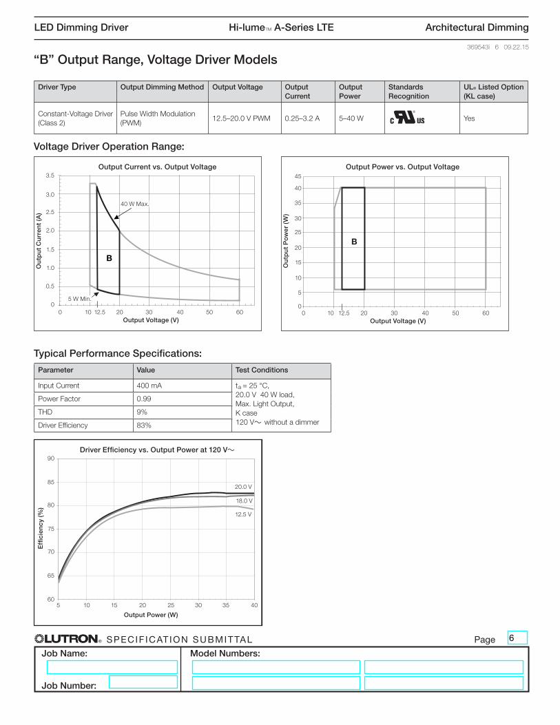
“B” Output Range, Voltage Driver Models
Typical Performance Specifications:
Output Current vs. Output Voltage
0
0.5
1
1.5
2
2.5
3
3.5
0 10 20 30 40 50 60
Output Voltage (V)
Out
put
Cur
rent
(A)
12.5
Output Power vs. Output Voltage
0
5
10
15
20
25
30
35
40
0 10 20 30 40 50 60
Output Voltage (V)
Out
put
Po
wer
(W)
12.5
60
65
70
75
80
85
90
5 10 15 20 25 30 35 40
Output Power (W)
Effi
cien
cy (%
)
Driver Efficiency vs. Output Power at 277 V~
B
B
Parameter Value Test Conditions
Input Current 400 mA ta = 25 °C, 20.0 V 40 W load, Max. Light Output, K case 120 V~ without a dimmer
Power Factor 0.99
THD 9%
Driver Efficiency 83%
45
Ou
tpu
t P
ow
er (
W)
40
Output Power vs. Output Voltage
0 10 12.5 20 30 40 50 60Output Voltage (V)
35
30
25
20
15
10
5
0
Ou
tpu
t C
urr
ent
(A)
3.5Output Current vs. Output Voltage
0 10 12.5 20 30 40 50 60Output Voltage (V)
3.0
2.5
2.0
1.5
1.0
0.5
0
Output Current vs. Output Voltage
0
0.5
1
1.5
2
2.5
3
3.5
0 10 20 30 40 50 60
Output Voltage (V)
Out
put
Cur
rent
(A)
12.5
Output Power vs. Output Voltage
0
5
10
15
20
25
30
35
40
0 10 20 30 40 50 60
Output Voltage (V)
Out
put
Po
wer
(W)
12.5
60
65
70
75
80
85
90
5 10 15 20 25 30 35 40
Output Power (W)
Effi
cien
cy (%
)
Driver Efficiency vs. Output Power at 277 V~
B
B
Voltage Driver Operation Range:
Output Current vs. Output Voltage
0
0.5
1
1.5
2
2.5
3
3.5
0 10 20 30 40 50 60
Output Voltage (V)
Out
put
Cur
rent
(A)
12.5
Output Power vs. Output Voltage
0
5
10
15
20
25
30
35
40
0 10 20 30 40 50 60
Output Voltage (V)
Out
put
Po
wer
(W)
12.5
60
65
70
75
80
85
90
5 10 15 20 25 30 35 40
Output Power (W)
Effi
cien
cy (%
)
Driver Efficiency vs. Output Power at 277 V~
B
B
5 W Min.
40 W Max.
Effi
cien
cy (%
)
90Driver Efficiency vs. Output Power at 120 V~
5 10 15 20 25 30 35 40
Output Power (W)
85
80
75
70
65
60
12.5 V
18.0 V
20.0 V
Driver Type Output Dimming Method Output Voltage Output Current
Output Power
Standards Recognition
UL® Listed Option (KL case)
Constant-Voltage Driver (Class 2)
Pulse Width Modulation (PWM)
12.5–20.0 V PWM 0.25–3.2 A 5–40 W Yes
6
® SPECIF ICAT ION SUBMITTAL Page
Job Name:
Job Number:
Model Numbers:
LED Dimming Driver Hi-lumeT A-Series LTE Architectural Dimming
369543i 7 09.22.15
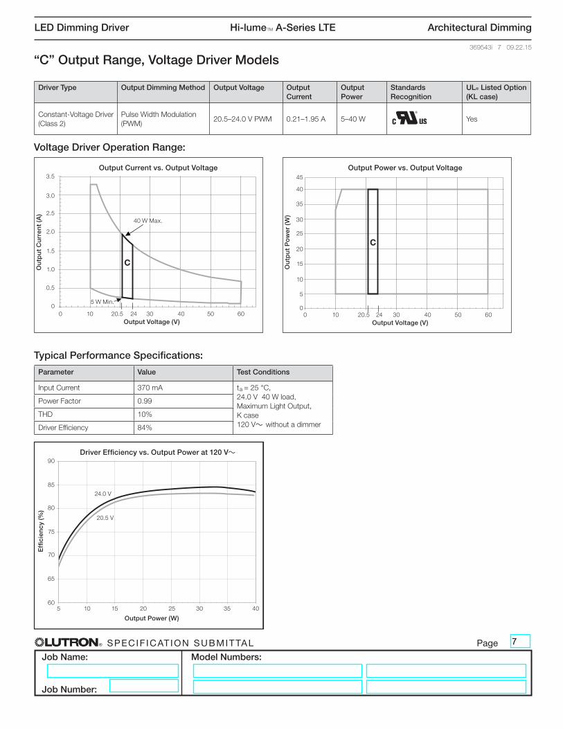
“C” Output Range, Voltage Driver Models
Typical Performance Specifications:
Output Current vs. Output Voltage
0
0.5
1
1.5
2
2.5
3
3.5
0 10 20.5 30 40 50 60
Output Voltage (V)
Out
put
Cur
rent
(A)
Output Power vs. Output Voltage
0
5
10
15
20
25
30
35
40
0 10 20.5 30 40 50 60
Output Voltage (V)
Out
put
Po
wer
(W)
60
65
70
75
80
85
90
5 10 15 20 25 30 35 40
Output Power (W)
Effi
cien
cy (%
)
Driver Efficiency vs. Output Power at 277 V~
24 24
C
C
Parameter Value Test Conditions
Input Current 370 mA ta = 25 °C, 24.0 V 40 W load, Maximum Light Output, K case 120 V~ without a dimmer
Power Factor 0.99
THD 10%
Driver Efficiency 84%
45
Ou
tpu
t P
ow
er (
W)
40
Output Power vs. Output Voltage
0 10 20.5 24 30 40 50 60Output Voltage (V)
35
30
25
20
15
10
5
0
Ou
tpu
t C
urr
ent
(A)
3.5Output Current vs. Output Voltage
0 10 20.5 24 30 40 50 60Output Voltage (V)
3.0
2.5
2.0
1.5
1.0
0.5
0
Output Current vs. Output Voltage
0
0.5
1
1.5
2
2.5
3
3.5
0 10 20.5 30 40 50 60
Output Voltage (V)
Out
put
Cur
rent
(A)
Output Power vs. Output Voltage
0
5
10
15
20
25
30
35
40
0 10 20.5 30 40 50 60
Output Voltage (V)
Out
put
Po
wer
(W)
60
65
70
75
80
85
90
5 10 15 20 25 30 35 40
Output Power (W)
Effi
cien
cy (%
)
Driver Efficiency vs. Output Power at 277 V~
24 24
C
C
Voltage Driver Operation Range:
Output Current vs. Output Voltage
0
0.5
1
1.5
2
2.5
3
3.5
0 10 20.5 30 40 50 60
Output Voltage (V)
Out
put
Cur
rent
(A)
Output Power vs. Output Voltage
0
5
10
15
20
25
30
35
40
0 10 20.5 30 40 50 60
Output Voltage (V)
Out
put
Po
wer
(W)
60
65
70
75
80
85
90
5 10 15 20 25 30 35 40
Output Power (W)
Effi
cien
cy (%
)
Driver Efficiency vs. Output Power at 277 V~
24 24
C
C
5 W Min.
40 W Max.
Effi
cien
cy (%
)
90Driver Efficiency vs. Output Power at 120 V~
5 10 15 20 25 30 35 40
Output Power (W)
85
80
75
70
65
60
20.5 V
24.0 V
Driver Type Output Dimming Method Output Voltage Output Current
Output Power
Standards Recognition
UL® Listed Option (KL case)
Constant-Voltage Driver (Class 2)
Pulse Width Modulation (PWM)
20.5–24.0 V PWM 0.21–1.95 A 5–40 W Yes
7
® SPECIF ICAT ION SUBMITTAL Page
Job Name:
Job Number:
Model Numbers:
LED Dimming Driver Hi-lumeT A-Series LTE Architectural Dimming
369543i 8 09.22.15
Typical Performance Specifications:
Output Current vs. Output Voltage
0
0.5
1
1.5
2
2.5
3
3.5
0 10 20 30 40 50 60
Output Voltage (V)
Out
put
Cur
rent
(A)
Output Power vs. Output Voltage
0
5
10
15
20
25
30
35
40
0 10 20 30 40 50 60
Output Voltage (V)
Out
put
Po
wer
(W)
60
65
70
75
80
85
90
5 10 15 20 25 30 35 40
Output Power (W)
Effi
cien
cy (%
)
Driver Efficiency vs. Output Power at 277 V~
24.5 24.5 3838
D
D
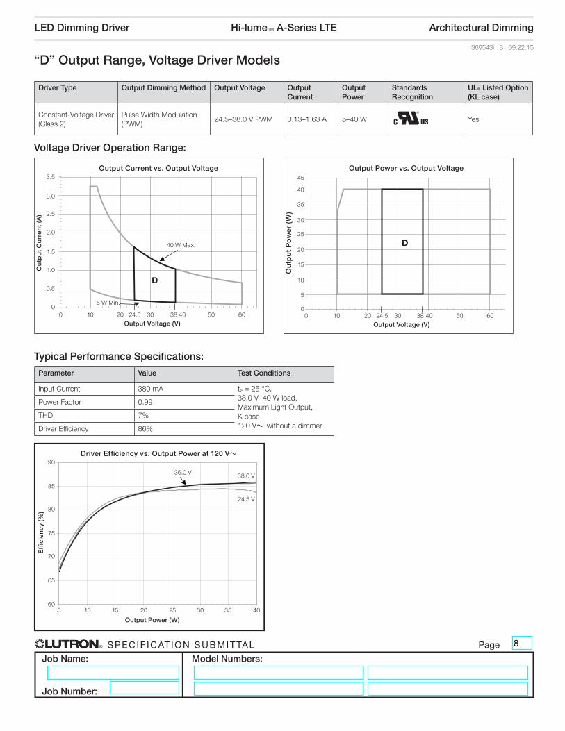
Parameter Value Test Conditions
Input Current 380 mA ta = 25 °C, 38.0 V 40 W load, Maximum Light Output, K case 120 V~ without a dimmer
Power Factor 0.99
THD 7%
Driver Efficiency 86%
45
Ou
tpu
t P
ow
er (
W)
40
Output Power vs. Output Voltage
0 10 20 24.5 30 38 40 50 60
Output Voltage (V)
35
30
25
20
15
10
5
0
Ou
tpu
t C
urr
ent
(A)
3.5Output Current vs. Output Voltage
0 10 20 24.5 30 38 40 50 60
Output Voltage (V)
3.0
2.5
2.0
1.5
1.0
0.5
0
“D” Output Range, Voltage Driver Models
Output Current vs. Output Voltage
0
0.5
1
1.5
2
2.5
3
3.5
0 10 20 30 40 50 60
Output Voltage (V)
Out
put
Cur
rent
(A)
Output Power vs. Output Voltage
0
5
10
15
20
25
30
35
40
0 10 20 30 40 50 60
Output Voltage (V)
Out
put
Po
wer
(W)
60
65
70
75
80
85
90
5 10 15 20 25 30 35 40
Output Power (W)
Effi
cien
cy (%
)
Driver Efficiency vs. Output Power at 277 V~
24.5 24.5 3838
D
D
Voltage Driver Operation Range:
Output Current vs. Output Voltage
0
0.5
1
1.5
2
2.5
3
3.5
0 10 20 30 40 50 60
Output Voltage (V)
Out
put
Cur
rent
(A)
Output Power vs. Output Voltage
0
5
10
15
20
25
30
35
40
0 10 20 30 40 50 60
Output Voltage (V)
Out
put
Po
wer
(W)
60
65
70
75
80
85
90
5 10 15 20 25 30 35 40
Output Power (W)
Effi
cien
cy (%
)
Driver Efficiency vs. Output Power at 277 V~
24.5 24.5 3838
D
D
5 W Min.
40 W Max.
Effi
cien
cy (%
)
90Driver Efficiency vs. Output Power at 120 V~
5 10 15 20 25 30 35 40
Output Power (W)
85
80
75
70
65
60
24.5 V
36.0 V 38.0 V
Driver Type Output Dimming Method Output Voltage Output Current
Output Power
Standards Recognition
UL® Listed Option (KL case)
Constant-Voltage Driver (Class 2)
Pulse Width Modulation (PWM)
24.5–38.0 V PWM 0.13–1.63 A 5–40 W Yes
8

® SPECIF ICAT ION SUBMITTAL Page
Job Name:
Job Number:
Model Numbers:
LED Dimming Driver Hi-lumeT A-Series LTE Architectural Dimming
369543i 9 09.22.15
Typical Performance Specifications:
Output Voltage vs. Output Current
Output Current (A)
Out
put
Vo
ltag
e (V
)
Output Power vs. Output Current
Output Current (A)
Out
put
Po
wer
(W)
0
10
20
30
40
50
54
60
0.20 0.50 0.20 0.500
5
10
15
20
25
30
35
40
0 0.35 0.7 1.05 1.4 1.75 2.1
60
65
70
75
80
85
90
Output Power (W)
Effi
cien
cy (%
)
Driver Efficiency vs. Output Power at 277 V~
6 9 12 15 18 21 24 27
0 0.35 0.7 1.41.05 2.1
E
E
Parameter Value Test ConditionsInput Current 260 mA ta = 25 °C,
0.50 A 27 W load, Maximum Light Output, K case 120 V~ without a dimmer
Power Factor 0.99
THD 10%
Driver Efficiency 83%
45
Ou
tpu
t P
ow
er (
W)
40
Output Power vs. Output Current
0 0.20 0.35 0.50 0.70 1.05 1.40 1.75 2.10Output Current (A)
35
30
25
20
15
10
5
0
Ou
tpu
t V
olt
age
(V)
60
Output Voltage vs. Output Current
0 0.20 0.35 0.50 0.70 1.05 1.40 1.75 2.10Output Current (A)
54
50
30
20
10
0
“E” Output Range, Current Driver Models
Output Voltage vs. Output Current
Output Current (A)
Out
put
Vo
ltag
e (V
)
Output Power vs. Output Current
Output Current (A)
Out
put
Po
wer
(W)
0
10
20
30
40
50
54
60
0.20 0.50 0.20 0.500
5
10
15
20
25
30
35
40
0 0.35 0.7 1.05 1.4 1.75 2.1
60
65
70
75
80
85
90
Output Power (W)
Effi
cien
cy (%
)
Driver Efficiency vs. Output Power at 277 V~
6 9 12 15 18 21 24 27
0 0.35 0.7 1.41.05 2.1
E
E
Current Driver Operation Range:
Output Voltage vs. Output Current
Output Current (A)
Out
put
Vo
ltag
e (V
)
Output Power vs. Output Current
Output Current (A)
Out
put
Po
wer
(W)
0
10
20
30
40
50
54
60
0.20 0.50 0.20 0.500
5
10
15
20
25
30
35
40
0 0.35 0.7 1.05 1.4 1.75 2.1
60
65
70
75
80
85
90
Output Power (W)
Effi
cien
cy (%
)
Driver Efficiency vs. Output Power at 277 V~
6 9 12 15 18 21 24 27
0 0.35 0.7 1.41.05 2.1
E
E
40
30 V Min.
54 V Max.
Effi
cien
cy (%
)
90Driver Efficiency vs. Output Power at 120 V~
6 9 12 15 18 21 24 27
Output Power (W)
85
80
75
70
65
60
0.20 A
0.35 A0.50 A
When using QwikFigTM technology, these models can be built from the following bulk units: K-case - LTEA4U1UKx-3ABLK *; M-case - LTEA4U1UMN-3ABLK* x = studded (S) or non-studded (N)
Driver Type Output Dimming Method Output Voltage
Output Current
Output Power
Standards Recognition UL® Listed Option (KL case)
Constant-Current Driver (Class 2)
Constant-Current Reduction (CCR)
30–54 V- 0.20–0.50 A 6–27 W YesType TL 82 º / 74 ºC - K-case
Type TL 86 º / 72 ºC - M-case
9

® SPECIF ICAT ION SUBMITTAL Page
Job Name:
Job Number:
Model Numbers:
LED Dimming Driver Hi-lumeT A-Series LTE Architectural Dimming
369543i 10 09.22.15
Typical Performance Specifications:
Output Voltage vs. Output Current
Output Current (A)
Out
put
Vo
ltag
e (V
)
Output Power vs. Output Current
Output Current (A)
Out
put
Po
wer
(W)
0
10
20
30
40
50
60
0 0.51 0.510
5
10
15
20
25
30
35
40
0 0.35 0.7 1.00 1.4 1.75 2.1
Output Power (W)
Effi
cien
cy (%
)
Driver Efficiency vs. Output Power at 277 V~
60
65
70
75
80
85
90
5 10 15 20 25 30 35 40
54
0.35 0.7 1.4 1.75 2.11.00
F F
Parameter Value Test ConditionsInput Current 390 mA ta = 25 °C,
1.00 A 40 W load, Maximum Light Output, K case 120 V~ without a dimmer
Power Factor 0.99
THD 7%
Driver Efficiency 82%
Ou
tpu
t V
olt
age
(V)
60
Output Voltage vs. Output Current
0 0.35 0.51 0.70 1.00 1.40 1.75 2.10Output Current (A)
5450
30
20
10
0
“F” Output Range, Current Driver Models
Output Voltage vs. Output Current
Output Current (A)
Out
put
Vo
ltag
e (V
)
Output Power vs. Output Current
Output Current (A)
Out
put
Po
wer
(W)
0
10
20
30
40
50
60
0 0.51 0.510
5
10
15
20
25
30
35
40
0 0.35 0.7 1.00 1.4 1.75 2.1
Output Power (W)
Effi
cien
cy (%
)
Driver Efficiency vs. Output Power at 277 V~
60
65
70
75
80
85
90
5 10 15 20 25 30 35 40
54
0.35 0.7 1.4 1.75 2.11.00
F F
Current Driver Operation Range:
Output Voltage vs. Output Current
Output Current (A)
Out
put
Vo
ltag
e (V
)
Output Power vs. Output Current
Output Current (A)
Out
put
Po
wer
(W)
0
10
20
30
40
50
60
0 0.51 0.510
5
10
15
20
25
30
35
40
0 0.35 0.7 1.00 1.4 1.75 2.1
Output Power (W)
Effi
cien
cy (%
)
Driver Efficiency vs. Output Power at 277 V~
60
65
70
75
80
85
90
5 10 15 20 25 30 35 40
54
0.35 0.7 1.4 1.75 2.11.00
F F
45
Ou
tpu
t P
ow
er (
W)
40
Output Power vs. Output Current
0 0.35 0.51 0.70 1.00 1.40 1.75 2.10Output Current (A)
35
30
25
20
15
10
5
0
40
30 V Min.
54 V Max.40 W Max.
Effi
cien
cy (%
)
90
85
80
75
70
65
60
Driver Efficiency vs. Output Power at 120 V~
15 20 25 30 35 40Output Power (W)
0.70 A 1.00 A0.51 A
When using QwikFigTM technology, these models can be built from the following bulk units: K-case - LTEA4U1UKx-3ABLK *; M-case - LTEA4U1UMN-3ABLK* x = studded (S) or non-studded (N)
Driver Type Output Dimming Method Output Voltage
Output Current
Output Power
Standards Recognition UL® Listed Option (KL case)
Constant-Current Driver (Class 2)
Constant-Current Reduction (CCR)
30–54 V- 0.51–1.00 A 15–40 W YesType TL 82 º / 74 ºC - K-case
Type TL 86 º / 72 ºC - M-case
10
® SPECIF ICAT ION SUBMITTAL Page
Job Name:
Job Number:
Model Numbers:
LED Dimming Driver Hi-lumeT A-Series LTE Architectural Dimming
369543i 11 09.22.15
Typical Performance Specifications:
Output Voltage vs. Output Current
Output Current (A)
Out
put
Vo
ltag
e (V
)
Output Power vs. Output Current
Output Current (A)
Out
put
Po
wer
(W)
0
10
20
30
40
50
60
0
5
10
15
20
25
30
35
40
0 0.35 0.7 1.05 1.4 1.75 2.1
Output Power (W)
Effi
cien
cy (%
)
Driver Efficiency vs. Output Power at 277 V~
8
0.20
60
65
70
75
80
85
90
2 4 6 8 10 12 14
0.35 0.7 1.4 1.75 2.11.050.20
GG
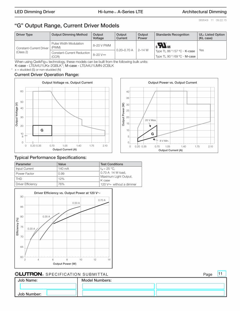
Parameter Value Test ConditionsInput Current 140 mA ta = 25 °C,
0.70 A 14 W load, Maximum Light Output, K case 120 V~ without a dimmer
Power Factor 0.99
THD 12%
Driver Efficiency 76%
Ou
tpu
t V
olt
age
(V)
60
Output Voltage vs. Output Current
0 0.20 0.35 0.70 1.05 1.40 1.75 2.10
Output Current (A)
8
50
30
20
10
0
40
Ou
tpu
t P
ow
er (
W)
40
Output Power vs. Output Current
0 0.20 0.35 0.70 1.05 1.40 1.75 2.10
Output Current (A)
35
30
25
20
15
10
5
0
“G” Output Range, Current Driver Models
Output Voltage vs. Output Current
Output Current (A)
Out
put
Vo
ltag
e (V
)
Output Power vs. Output Current
Output Current (A)
Out
put
Po
wer
(W)
0
10
20
30
40
50
60
0
5
10
15
20
25
30
35
40
0 0.35 0.7 1.05 1.4 1.75 2.1
Output Power (W)
Effi
cien
cy (%
)
Driver Efficiency vs. Output Power at 277 V~
8
0.20
60
65
70
75
80
85
90
2 4 6 8 10 12 14
0.35 0.7 1.4 1.75 2.11.050.20
GG
Current Driver Operation Range:
Output Voltage vs. Output Current
Output Current (A)
Out
put
Vo
ltag
e (V
)
Output Power vs. Output Current
Output Current (A)
Out
put
Po
wer
(W)
0
10
20
30
40
50
60
0
5
10
15
20
25
30
35
40
0 0.35 0.7 1.05 1.4 1.75 2.1
Output Power (W)
Effi
cien
cy (%
)
Driver Efficiency vs. Output Power at 277 V~
8
0.20
60
65
70
75
80
85
90
2 4 6 8 10 12 14
0.35 0.7 1.4 1.75 2.11.050.20
GG
8 V Min.
20 V Max.
Effi
cien
cy (%
)
90Driver Efficiency vs. Output Power at 120 V~
2 4 6 8 10 12 14
Output Power (W)
85
80
75
70
65
60
0.20 A
0.35 A
0.50 A0.70 A
When using QwikFigTM technology, these models can be built from the following bulk units: K-case - LTEA4U1UKx-2GBLK *; M-case - LTEA4U1UMN-2CBLK* x = studded (S) or non-studded (N)
Driver Type Output Dimming Method Output Voltage
Output Current
Output Power
Standards Recognition UL® Listed Option (KL case)
Constant-Current Driver (Class 2)
Pulse Width Modulation (PWM)
8–20 V PWM
0.20–0.70 A 2–14 W YesConstant-Current Reduction (CCR)
8–20 V-Type TL 86 º / 57 ºC - K-case
Type TL 90 º / 69 ºC - M-case
11
® SPECIF ICAT ION SUBMITTAL Page
Job Name:
Job Number:
Model Numbers:
LED Dimming Driver Hi-lumeT A-Series LTE Architectural Dimming
369543i 12 09.22.15
Typical Performance Specifications:
Output Voltage vs. Output Current
Output Current (A)
Out
put
Vo
ltag
e (V
)
Output Power vs. Output Current
Output Current (A)
Out
put
Po
wer
(W)
0
10
20
30
40
50
60
0 0.35 0.7 1.4 1.75 2.10
5
10
15
20
25
30
35
40
Output Power (W)
Effi
cien
cy (%
)
Driver Efficiency vs. Output Power at 277 V~
1.05
15
38
0.20 0 0.35 0.7 1.4 1.75 2.11.050.20
60
65
70
75
80
85
90
3 8 13 18 23
H
H
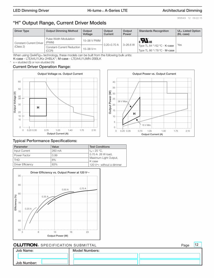
Parameter Value Test ConditionsInput Current 260 mA ta = 25 °C,
0.70 A 26 W load, Maximum Light Output, K case 120 V~ without a dimmer
Power Factor 0.99
THD 8%
Driver Efficiency 83%
Ou
tpu
t P
ow
er (
W)
40
Output Power vs. Output Current
0 0.20 0.35 0.70 1.05 1.40 1.75 2.10
Output Current (A)
35
30
25
20
15
10
5
0
Ou
tpu
t V
olt
age
(V)
60
Output Voltage vs. Output Current
0 0.20 0.35 0.70 1.05 1.40 1.75 2.10
Output Current (A)
15
50
30
20
10
0
40
“H” Output Range, Current Driver Models
Output Voltage vs. Output Current
Output Current (A)
Out
put
Vo
ltag
e (V
)
Output Power vs. Output Current
Output Current (A)
Out
put
Po
wer
(W)
0
10
20
30
40
50
60
0 0.35 0.7 1.4 1.75 2.10
5
10
15
20
25
30
35
40
Output Power (W)
Effi
cien
cy (%
)
Driver Efficiency vs. Output Power at 277 V~
1.05
15
38
0.20 0 0.35 0.7 1.4 1.75 2.11.050.20
60
65
70
75
80
85
90
3 8 13 18 23
H
H
Current Driver Operation Range:
Output Voltage vs. Output Current
Output Current (A)
Out
put
Vo
ltag
e (V
)
Output Power vs. Output Current
Output Current (A)
Out
put
Po
wer
(W)
0
10
20
30
40
50
60
0 0.35 0.7 1.4 1.75 2.10
5
10
15
20
25
30
35
40
Output Power (W)
Effi
cien
cy (%
)
Driver Efficiency vs. Output Power at 277 V~
1.05
15
38
0.20 0 0.35 0.7 1.4 1.75 2.11.050.20
60
65
70
75
80
85
90
3 8 13 18 23
H
H
38
15 V Min.
38 V Max.
Effi
cien
cy (%
)
90Driver Efficiency vs. Output Power at 120 V~
3 8 13 18 23
Output Power (W)
85
80
75
70
65
60
0.20 A
0.35 A
0.50 A 0.70 A
When using QwikFigTM technology, these models can be built from the following bulk units: K-case - LTEA4U1UKx-2HBLK *; M-case - LTEA4U1UMN-2BBLK* x = studded (S) or non-studded (N)
Driver Type Output Dimming Method Output Voltage
Output Current
Output Power
Standards Recognition UL® Listed Option (KL case)
Constant-Current Driver (Class 2)
Pulse Width Modulation (PWM)
15–38 V PWM
0.20–0.70 A 3–26.6 W YesConstant-Current Reduction (CCR)
15–38 V-Type TL 84 º / 62 ºC - K-case
Type TL 86 º / 78 ºC - M-case
12
® SPECIF ICAT ION SUBMITTAL Page
Job Name:
Job Number:
Model Numbers:
LED Dimming Driver Hi-lumeT A-Series LTE Architectural Dimming
369543i 13 09.22.15
Typical Performance Specifications:
Output Voltage vs. Output Current
Output Current (A)
Out
put
Vo
ltag
e (V
)
Output Power vs. Output Current
Output Current (A)
Out
put
Po
wer
(W)
0
10
20
30
40
50
60
0
5
10
15
20
25
30
35
40
0 0.35 0.7 1.05 1.4 1.75 2.10.200 0.35 0.71 1.4 1.751.05 2.1
8
Output Power (W)
Effi
cien
cy (%
)
Driver Efficiency vs. Output Power at 277 V~
60
65
70
75
80
85
90
6 9 12 15 18 21
II
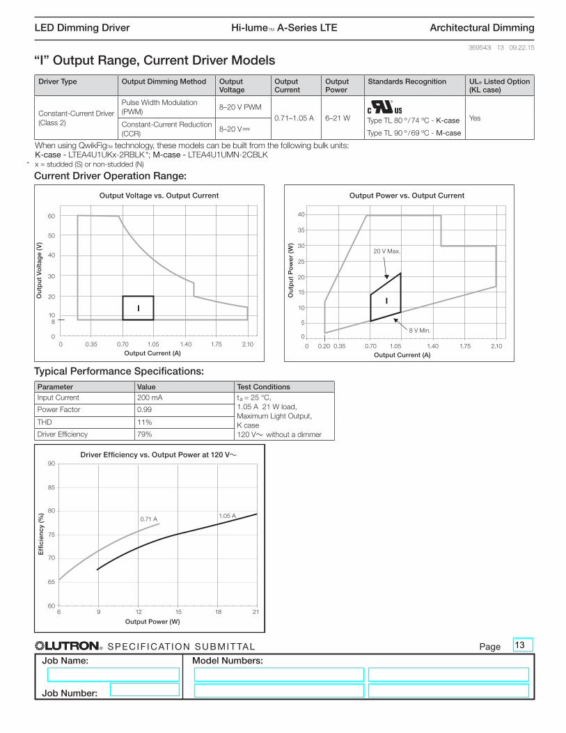
Parameter Value Test ConditionsInput Current 200 mA ta = 25 °C,
1.05 A 21 W load, Maximum Light Output, K case 120 V~ without a dimmer
Power Factor 0.99
THD 11%
Driver Efficiency 79%
“I” Output Range, Current Driver Models
Output Voltage vs. Output Current
Output Current (A)
Out
put
Vo
ltag
e (V
)
Output Power vs. Output Current
Output Current (A)
Out
put
Po
wer
(W)
0
10
20
30
40
50
60
0
5
10
15
20
25
30
35
40
0 0.35 0.7 1.05 1.4 1.75 2.10.200 0.35 0.71 1.4 1.751.05 2.1
8
Output Power (W)
Effi
cien
cy (%
)
Driver Efficiency vs. Output Power at 277 V~
60
65
70
75
80
85
90
6 9 12 15 18 21
II
Current Driver Operation Range:
Output Voltage vs. Output Current
Output Current (A)
Out
put
Vo
ltag
e (V
)
Output Power vs. Output Current
Output Current (A)
Out
put
Po
wer
(W)
0
10
20
30
40
50
60
0
5
10
15
20
25
30
35
40
0 0.35 0.7 1.05 1.4 1.75 2.10.200 0.35 0.71 1.4 1.751.05 2.1
8
Output Power (W)
Effi
cien
cy (%
)
Driver Efficiency vs. Output Power at 277 V~
60
65
70
75
80
85
90
6 9 12 15 18 21
II
Ou
tpu
t P
ow
er (
W)
40
Output Power vs. Output Current
0 0.20 0.35 0.70 1.05 1.40 1.75 2.10
Output Current (A)
35
30
25
20
15
10
5
08 V Min.
20 V Max.
Ou
tpu
t V
olt
age
(V)
60
Output Voltage vs. Output Current
0 0.35 0.70 1.05 1.40 1.75 2.10
Output Current (A)
8
50
30
20
10
0
40
Effi
cien
cy (%
)
90Driver Efficiency vs. Output Power at 120 V~
6 9 12 15 18 21
Output Power (W)
85
80
75
70
65
60
0.71 A 1.05 A
When using QwikFigTM technology, these models can be built from the following bulk units: K-case - LTEA4U1UKx-2RBLK *; M-case - LTEA4U1UMN-2CBLK* x = studded (S) or non-studded (N)
Driver Type Output Dimming Method Output Voltage
Output Current
Output Power
Standards Recognition UL® Listed Option (KL case)
Constant-Current Driver (Class 2)
Pulse Width Modulation (PWM)
8–20 V PWM
0.71–1.05 A 6–21 W YesConstant-Current Reduction (CCR)
8–20 V-Type TL 80 º / 74 ºC - K-case
Type TL 90 º / 69 ºC - M-case
13
® SPECIF ICAT ION SUBMITTAL Page
Job Name:
Job Number:
Model Numbers:
LED Dimming Driver Hi-lumeT A-Series LTE Architectural Dimming
369543i 14 09.22.15
Typical Performance Specifications:
Output Voltage vs. Output Current
Output Current (A)
Out
put
Vo
ltag
e (V
)
Output Power vs. Output Current
Output Current (A)
Out
put
Po
wer
(W)
0
10
20
30
40
50
60
0
5
10
15
20
25
30
35
40
0 0.35 0.71 1.05 1.4 1.75 2.1
15
38
0 0.35 1.05 1.4 1.75 2.10.71
Output Power (W)
Effi
cien
cy (%
)
Driver Efficiency vs. Output Power at 277 V~
60
65
70
75
80
85
90
10 15 20 25 30 35 40
J
J
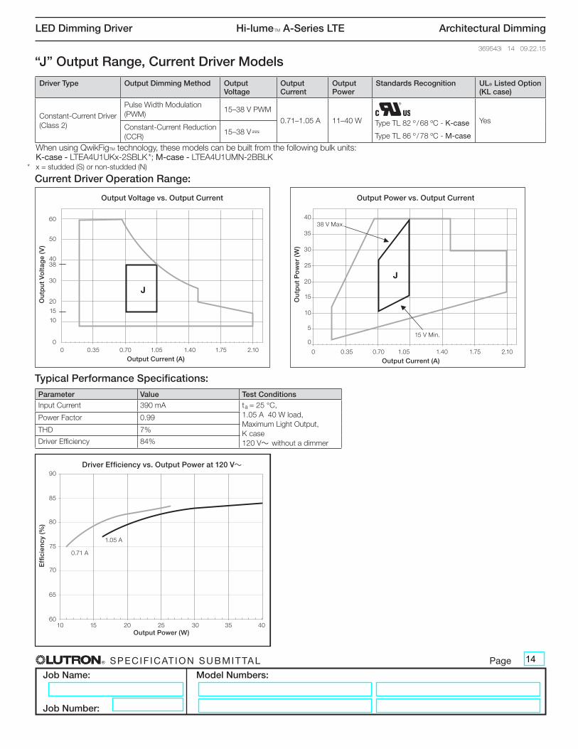
Parameter Value Test ConditionsInput Current 390 mA ta = 25 °C,
1.05 A 40 W load, Maximum Light Output, K case 120 V~ without a dimmer
Power Factor 0.99
THD 7%
Driver Efficiency 84%
“J” Output Range, Current Driver Models
Output Voltage vs. Output Current
Output Current (A)
Out
put
Vo
ltag
e (V
)
Output Power vs. Output Current
Output Current (A)
Out
put
Po
wer
(W)
0
10
20
30
40
50
60
0
5
10
15
20
25
30
35
40
0 0.35 0.71 1.05 1.4 1.75 2.1
15
38
0 0.35 1.05 1.4 1.75 2.10.71
Output Power (W)
Effi
cien
cy (%
)
Driver Efficiency vs. Output Power at 277 V~
60
65
70
75
80
85
90
10 15 20 25 30 35 40
J
J
Current Driver Operation Range:
Output Voltage vs. Output Current
Output Current (A)
Out
put
Vo
ltag
e (V
)
Output Power vs. Output Current
Output Current (A)
Out
put
Po
wer
(W)
0
10
20
30
40
50
60
0
5
10
15
20
25
30
35
40
0 0.35 0.71 1.05 1.4 1.75 2.1
15
38
0 0.35 1.05 1.4 1.75 2.10.71
Output Power (W)
Effi
cien
cy (%
)
Driver Efficiency vs. Output Power at 277 V~
60
65
70
75
80
85
90
10 15 20 25 30 35 40
J
J
Ou
tpu
t P
ow
er (
W)
40
Output Power vs. Output Current
0 0.35 0.70 1.05 1.40 1.75 2.10
Output Current (A)
35
30
25
20
15
10
5
0
15
15 V Min.
38 V Max.
Ou
tpu
t V
olt
age
(V)
60
Output Voltage vs. Output Current
0 0.35 0.70 1.05 1.40 1.75 2.10
Output Current (A)
38
50
30
20
10
0
40
Effi
cien
cy (%
)
90Driver Efficiency vs. Output Power at 120 V~
10 15 20 25 30 35 40 Output Power (W)
85
80
75
70
65
60
0.71 A
1.05 A
When using QwikFigTM technology, these models can be built from the following bulk units: K-case - LTEA4U1UKx-2SBLK *; M-case - LTEA4U1UMN-2BBLK* x = studded (S) or non-studded (N)
Driver Type Output Dimming Method Output Voltage
Output Current
Output Power
Standards Recognition UL® Listed Option (KL case)
Constant-Current Driver (Class 2)
Pulse Width Modulation (PWM)
15–38 V PWM
0.71–1.05 A 11–40 W YesConstant-Current Reduction (CCR)
15–38 V-Type TL 82 º / 68 ºC - K-case
Type TL 86 º / 78 ºC - M-case
14
® SPECIF ICAT ION SUBMITTAL Page
Job Name:
Job Number:
Model Numbers:
LED Dimming Driver Hi-lumeT A-Series LTE Architectural Dimming
369543i 15 09.22.15
Typical Performance Specifications:
Output Voltage vs. Output Current
Output Current (A)
Out
put
Vo
ltag
e (V
)
Output Power vs. Output Current
Output Current (A)
Out
put
Po
wer
(W)
0
10
20
30
40
50
60
0
5
10
15
20
25
30
35
40
0 0.35 0.7 1.05 1.4 1.75 2.10 0.35 1.06 1.4 1.75 2.10.7
Output Power (W)
Effi
cien
cy (%
)
Driver Efficiency vs. Output Power at 277 V~
60
65
70
75
80
85
90
9 11 13 15 17 19 21 23 25 27 29
8
1.51.5
K
K
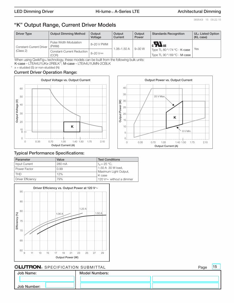
Parameter Value Test ConditionsInput Current 280 mA ta = 25 °C,
1.50 A 30 W load, Maximum Light Output, K case 120 V~ without a dimmer
Power Factor 0.99
THD 12%
Driver Efficiency 79%
“K” Output Range, Current Driver Models
Output Voltage vs. Output Current
Output Current (A)
Out
put
Vo
ltag
e (V
)
Output Power vs. Output Current
Output Current (A)
Out
put
Po
wer
(W)
0
10
20
30
40
50
60
0
5
10
15
20
25
30
35
40
0 0.35 0.7 1.05 1.4 1.75 2.10 0.35 1.06 1.4 1.75 2.10.7
Output Power (W)
Effi
cien
cy (%
)
Driver Efficiency vs. Output Power at 277 V~
60
65
70
75
80
85
90
9 11 13 15 17 19 21 23 25 27 29
8
1.51.5
K
K
Current Driver Operation Range:
Output Voltage vs. Output Current
Output Current (A)
Out
put
Vo
ltag
e (V
)
Output Power vs. Output Current
Output Current (A)
Out
put
Po
wer
(W)
0
10
20
30
40
50
60
0
5
10
15
20
25
30
35
40
0 0.35 0.7 1.05 1.4 1.75 2.10 0.35 1.06 1.4 1.75 2.10.7
Output Power (W)
Effi
cien
cy (%
)
Driver Efficiency vs. Output Power at 277 V~
60
65
70
75
80
85
90
9 11 13 15 17 19 21 23 25 27 29
8
1.51.5
K
KO
utp
ut
Po
wer
(W
)
40
Output Power vs. Output Current
0 0.35 0.70 1.05 1.40 1.50 1.75 2.10
Output Current (A)
35
30
25
20
15
10
5
0
8 V Min.
20 V Max.
Ou
tpu
t V
olt
age
(V)
60
Output Voltage vs. Output Current
0 0.35 0.70 1.05 1.40 1.50 1.75 2.10
Output Current (A)
8
50
30
20
10
0
40
Effi
cien
cy (%
)
90Driver Efficiency vs. Output Power at 120 V~
9 11 13 15 17 19 21 23 25 27 29
Output Power (W)
85
80
75
70
65
60
1.20 A
1.06 A 1.50 A
When using QwikFigTM technology, these models can be built from the following bulk units: K-case - LTEA4U1UKx-2RBLK *; M-case - LTEA4U1UMN-2CBLK* x = studded (S) or non-studded (N)
Driver Type Output Dimming Method Output Voltage
Output Current
Output Power
Standards Recognition UL® Listed Option (KL case)
Constant-Current Driver (Class 2)
Pulse Width Modulation (PWM)
8–20 V PWM
1.06–1.50 A 9–30 W YesConstant-Current Reduction (CCR)
8–20 V-Type TL 80 º / 74 ºC - K-case
Type TL 90 º / 69 ºC - M-case
15
® SPECIF ICAT ION SUBMITTAL Page
Job Name:
Job Number:
Model Numbers:
LED Dimming Driver Hi-lumeT A-Series LTE Architectural Dimming
369543i 16 09.22.15
Typical Performance Specifications:
Output Voltage vs. Output Current
Output Current (A)
Out
put
Vo
ltag
e (V
)
Output Power vs. Output Current
Output Current (A)
Out
put
Po
wer
(W)
0
10
20
30
40
50
60
0
5
10
15
20
25
30
35
40
0 0.35 0.7 1.05 1.4 1.75 2.10 0.35 1.06 1.4 1.75 2.10.7
15
1.51.5
Output Power (W)
Effi
cien
cy (%
)
Driver Efficiency vs. Output Power at 277 V~
60
65
70
75
80
85
90
16 19 22 25 28 31 34 37 40
L
L
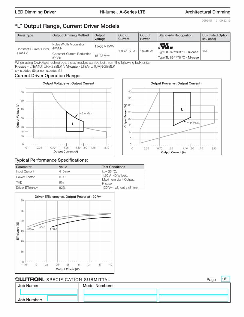
Parameter Value Test ConditionsInput Current 410 mA ta = 25 °C,
1.50 A 40 W load, Maximum Light Output, K case 120 V~ without a dimmer
Power Factor 0.99
THD 9%
Driver Efficiency 82%
Ou
tpu
t P
ow
er (
W)
40
Output Power vs. Output Current
0 0.35 0.70 1.05 1.40 1.50 1.75 2.10
Output Current (A)
35
30
25
20
15
10
5
0
Ou
tpu
t V
olt
age
(V)
60
Output Voltage vs. Output Current
0 0.35 0.70 1.06 1.40 1.50 1.75 2.10
Output Current (A)
15
50
30
20
10
0
40
“L” Output Range, Current Driver Models
Output Voltage vs. Output Current
Output Current (A)
Out
put
Vo
ltag
e (V
)
Output Power vs. Output Current
Output Current (A)
Out
put
Po
wer
(W)
0
10
20
30
40
50
60
0
5
10
15
20
25
30
35
40
0 0.35 0.7 1.05 1.4 1.75 2.10 0.35 1.06 1.4 1.75 2.10.7
15
1.51.5
Output Power (W)
Effi
cien
cy (%
)
Driver Efficiency vs. Output Power at 277 V~
60
65
70
75
80
85
90
16 19 22 25 28 31 34 37 40
L
L
Current Driver Operation Range:
Output Voltage vs. Output Current
Output Current (A)
Out
put
Vo
ltag
e (V
)
Output Power vs. Output Current
Output Current (A)
Out
put
Po
wer
(W)
0
10
20
30
40
50
60
0
5
10
15
20
25
30
35
40
0 0.35 0.7 1.05 1.4 1.75 2.10 0.35 1.06 1.4 1.75 2.10.7
15
1.51.5
Output Power (W)
Effi
cien
cy (%
)
Driver Efficiency vs. Output Power at 277 V~
60
65
70
75
80
85
90
16 19 22 25 28 31 34 37 40
L
L 15 V Min.
40 W Max.
Effi
cien
cy (%
)
90Driver Efficiency vs. Output Power at 120 V~
16 19 22 25 28 31 34 37 40
Output Power (W)
85
80
75
70
65
60
1.20 A1.06 A 1.50 A
When using QwikFigTM technology, these models can be built from the following bulk units: K-case - LTEA4U1UKx-2SBLK *; M-case - LTEA4U1UMN-2BBLK* x = studded (S) or non-studded (N)
Driver Type Output Dimming Method Output Voltage
Output Current
Output Power
Standards Recognition UL® Listed Option (KL case)
Constant-Current Driver (Class 2)
Pulse Width Modulation (PWM)
15–38 V PWM
1.06–1.50 A 16–40 W YesConstant-Current Reduction (CCR)
15–38 V-Type TL 82 º / 68 ºC - K-case
Type TL 86 º / 78 ºC - M-case
16
® SPECIF ICAT ION SUBMITTAL Page
Job Name:
Job Number:
Model Numbers:
LED Dimming Driver Hi-lumeT A-Series LTE Architectural Dimming
369543i 17 09.22.15
Typical Performance Specifications:
Output Voltage vs. Output Current
Out
put
Vo
ltag
e (V
)
Output Power vs. Output Current
Out
put
Po
wer
(W)
Output Current (A)
0
10
20
30
40
50
60
8
0 0.35 0.7 1.05 1.4 1.75 2.11.51
Output Current (A)
0
5
10
15
20
25
30
35
40
0 0.35 0.7 1.05 1.4 1.75 2.11.51
Output Power (W)
Effi
cien
cy (%
)
Driver Efficiency vs. Output Power at 277 V~
60
65
70
75
80
85
90
12 14 16 18 20 22 24 26 28 30
M
M
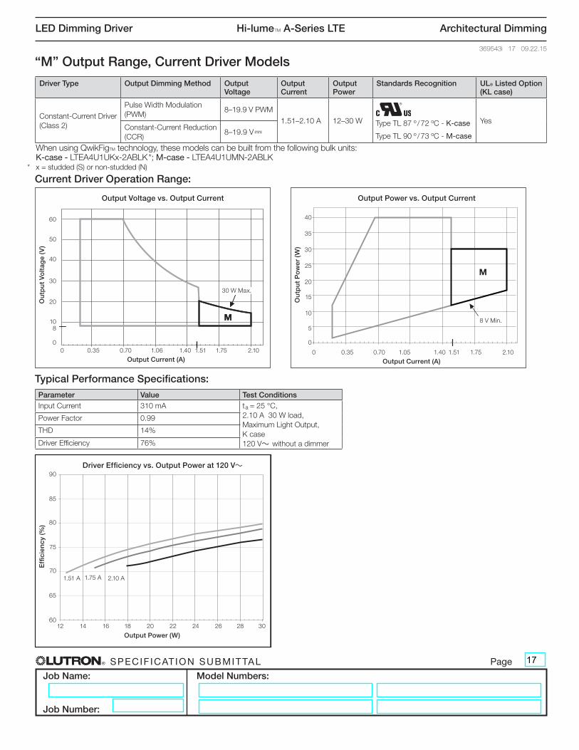
Parameter Value Test ConditionsInput Current 310 mA ta = 25 °C,
2.10 A 30 W load, Maximum Light Output, K case 120 V~ without a dimmer
Power Factor 0.99
THD 14%
Driver Efficiency 76%
Ou
tpu
t P
ow
er (
W)
40
Output Power vs. Output Current
0 0.35 0.70 1.05 1.40 1.51 1.75 2.10
Output Current (A)
35
30
25
20
15
10
5
0
Ou
tpu
t V
olt
age
(V)
60
Output Voltage vs. Output Current
0 0.35 0.70 1.06 1.40 1.51 1.75 2.10
Output Current (A)
8
50
30
20
10
0
40
Output Voltage vs. Output Current
Out
put
Vo
ltag
e (V
)
Output Power vs. Output Current
Out
put
Po
wer
(W)
Output Current (A)
0
10
20
30
40
50
60
8
0 0.35 0.7 1.05 1.4 1.75 2.11.51
Output Current (A)
0
5
10
15
20
25
30
35
40
0 0.35 0.7 1.05 1.4 1.75 2.11.51
Output Power (W)
Effi
cien
cy (%
)
Driver Efficiency vs. Output Power at 277 V~
60
65
70
75
80
85
90
12 14 16 18 20 22 24 26 28 30
M
M
“M” Output Range, Current Driver Models
Output Voltage vs. Output Current
Out
put
Vo
ltag
e (V
)
Output Power vs. Output Current
Out
put
Po
wer
(W)
Output Current (A)
0
10
20
30
40
50
60
8
0 0.35 0.7 1.05 1.4 1.75 2.11.51
Output Current (A)
0
5
10
15
20
25
30
35
40
0 0.35 0.7 1.05 1.4 1.75 2.11.51
Output Power (W)
Effi
cien
cy (%
)
Driver Efficiency vs. Output Power at 277 V~
60
65
70
75
80
85
90
12 14 16 18 20 22 24 26 28 30
M
M
Current Driver Operation Range:
Output Voltage vs. Output Current
Out
put
Vo
ltag
e (V
)
Output Power vs. Output Current
Out
put
Po
wer
(W)
Output Current (A)
0
10
20
30
40
50
60
8
0 0.35 0.7 1.05 1.4 1.75 2.11.51
Output Current (A)
0
5
10
15
20
25
30
35
40
0 0.35 0.7 1.05 1.4 1.75 2.11.51
Output Power (W)
Effi
cien
cy (%
)
Driver Efficiency vs. Output Power at 277 V~
60
65
70
75
80
85
90
12 14 16 18 20 22 24 26 28 30
M
M
8 V Min.
30 W Max.
Effi
cien
cy (%
)
90Driver Efficiency vs. Output Power at 120 V~
12 14 16 18 20 22 24 26 28 30
Output Power (W)
85
80
75
70
65
60
1.75 A1.51 A 2.10 A
When using QwikFigTM technology, these models can be built from the following bulk units: K-case - LTEA4U1UKx-2ABLK *; M-case - LTEA4U1UMN-2ABLK* x = studded (S) or non-studded (N)
Driver Type Output Dimming Method Output Voltage
Output Current
Output Power
Standards Recognition UL® Listed Option (KL case)
Constant-Current Driver (Class 2)
Pulse Width Modulation (PWM)
8–19.9 V PWM
1.51–2.10 A 12–30 W YesConstant-Current Reduction (CCR)
8–19.9 V-Type TL 87 º / 72 ºC - K-case
Type TL 90 º / 73 ºC - M-case
17

® SPECIF ICAT ION SUBMITTAL Page
Job Name:
Job Number:
Model Numbers:
LED Dimming Driver Hi-lumeT A-Series LTE Architectural Dimming
369543i 18 09.22.15
Typical Performance Specifications:
Output Current vs. Output Voltage
Out
put
Cur
rent
(A)
Output Power vs. Output Voltage
Out
put
Po
wer
(W)
Output Voltage (V)
38.5
0
5
10
15
20
25
30
35
40
0
0.5
1
1.5
2
2.5
3
3.5
0 10 20 30 40 50 60
Output Voltage (V)
38.50 10 20 30 40 50 60
60
65
70
75
80
85
90
5 10 15 20 25 30 35 40
Output Power (W)
Effi
cien
cy (%
)
Driver Efficiency vs. Output Power at 277 V~
X
X
Parameter Value Test Conditions
Input Current 390 mA ta = 25 °C, 60.0 V 40 W load, Maximum Light Output, K case 120 V~ without a dimmer
Power Factor 0.99
THD 10%
Driver Efficiency 86%
“X” Output Range, Voltage Driver Models
Output Current vs. Output Voltage
Out
put
Cur
rent
(A)
Output Power vs. Output Voltage
Out
put
Po
wer
(W)
Output Voltage (V)
38.5
0
5
10
15
20
25
30
35
40
0
0.5
1
1.5
2
2.5
3
3.5
0 10 20 30 40 50 60
Output Voltage (V)
38.50 10 20 30 40 50 60
60
65
70
75
80
85
90
5 10 15 20 25 30 35 40
Output Power (W)
Effi
cien
cy (%
)
Driver Efficiency vs. Output Power at 277 V~
X
X
Voltage Driver Operation Range:
Output Current vs. Output Voltage
Out
put
Cur
rent
(A)
Output Power vs. Output Voltage
Out
put
Po
wer
(W)
Output Voltage (V)
38.5
0
5
10
15
20
25
30
35
40
0
0.5
1
1.5
2
2.5
3
3.5
0 10 20 30 40 50 60
Output Voltage (V)
38.50 10 20 30 40 50 60
60
65
70
75
80
85
90
5 10 15 20 25 30 35 40
Output Power (W)
Effi
cien
cy (%
)
Driver Efficiency vs. Output Power at 277 V~
X
X
Ou
tpu
t P
ow
er (
W)
Output Power vs. Output Voltage
0 10 20 30 38.5 40 50 60
Output Voltage (V)
40
35
30
25
20
0
15
10
5
40 W Max.
5 W Min.
Ou
tpu
t C
urr
ent
(A)
3.5
Output Current vs. Output Voltage
0 10 20 30 38.5 40 50 60
Output Voltage (V)
1.0
3.0
2.0
1.5
0.5
0
2.5
Effi
cien
cy (%
)
90Driver Efficiency vs. Output Power at 120 V~
5 10 15 20 25 30 35 40
Output Power (W)
85
80
75
70
65
60
48.0 V
38.5 V60.0 V
Driver Type Output Dimming Method Output Voltage Output Current
Output Power
Standards Recognition
UL® Listed Option (KL case)
Constant-Voltage Driver (Isolated, Non-Class 2)
Pulse Width Modulation (PWM)
38.5–60.0 V PWM 0.08–1.04 A 5–40 W No
18
® SPECIF ICAT ION SUBMITTAL Page
Job Name:
Job Number:
Model Numbers:
LED Dimming Driver Hi-lumeT A-Series LTE Architectural Dimming
369543i 19 09.22.15
Typical Performance Specifications:
Output Voltage vs. Output Current
Out
put
Vo
ltag
e (V
)
Output Power vs. Output Current
Out
put
Po
wer
(W)
Output Current (A)
0
10
20
30
40
50
60
0 0.35 0.7 1.05 1.4 1.75 2.1
Output Current (A)
0
5
10
15
20
25
30
35
40
0 0.35 0.7 1.05 1.4 1.75 2.10.500.200.500.20
Output Power (W)
Effi
cien
cy (%
)
Driver Efficiency vs. Output Power at 277 V~
60
65
70
75
80
85
90
6 9 12 15 18 21 24 27 30
Y
Y
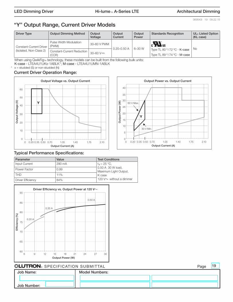
Parameter Value Test ConditionsInput Current 290 mA ta = 25 °C,
0.50 A 30 W load, Maximum Light Output, K case 120 V~ without a dimmer
Power Factor 0.99
THD 11%
Driver Efficiency 84%
“Y” Output Range, Current Driver Models
Output Voltage vs. Output Current
Out
put
Vo
ltag
e (V
)
Output Power vs. Output Current
Out
put
Po
wer
(W)
Output Current (A)
0
10
20
30
40
50
60
0 0.35 0.7 1.05 1.4 1.75 2.1
Output Current (A)
0
5
10
15
20
25
30
35
40
0 0.35 0.7 1.05 1.4 1.75 2.10.500.200.500.20
Output Power (W)
Effi
cien
cy (%
)
Driver Efficiency vs. Output Power at 277 V~
60
65
70
75
80
85
90
6 9 12 15 18 21 24 27 30
Y
Y
Current Driver Operation Range:
Output Voltage vs. Output Current
Out
put
Vo
ltag
e (V
)
Output Power vs. Output Current
Out
put
Po
wer
(W)
Output Current (A)
0
10
20
30
40
50
60
0 0.35 0.7 1.05 1.4 1.75 2.1
Output Current (A)
0
5
10
15
20
25
30
35
40
0 0.35 0.7 1.05 1.4 1.75 2.10.500.200.500.20
Output Power (W)
Effi
cien
cy (%
)
Driver Efficiency vs. Output Power at 277 V~
60
65
70
75
80
85
90
6 9 12 15 18 21 24 27 30
Y
YO
utp
ut
Po
wer
(W
)
Output Power vs. Output Current
0 0.20 0.35 0.50 0.70 1.05 1.40 1.75 2.10
Output Current (A)
40
35
30
25
20
0
15
10
5
60 V Max.
30 V Min.
Ou
tpu
t V
olt
age
(V)
60
Output Voltage vs. Output Current
0 0.20 0.35 0.50 0.70 1.05 1.40 1.75 2.10
Output Current (A)
50
30
20
10
0
40
Effi
cien
cy (%
)
90Driver Efficiency vs. Output Power at 120 V~
6 9 12 15 18 21 24 27 30
Output Power (W)
85
80
75
70
65
60
0.35 A
0.20 A
0.50 A
When using QwikFigTM technology, these models can be built from the following bulk units: K-case - LTEA4U1UKx-1ABLK *; M-case - LTEA4U1UMN-1ABLK* x = studded (S) or non-studded (N)
Driver Type Output Dimming Method Output Voltage
Output Current
Output Power
Standards Recognition UL® Listed Option (KL case)
Constant-Current Driver (Isolated, Non-Class 2)
Pulse Width Modulation (PWM)
30–60 V PWM
0.20–0.50 A 6–30 W NoConstant-Current Reduction (CCR)
30–60 V-Type TL 80 º / 72 ºC - K-case
Type TL 89 º / 74 ºC - M-case
19
® SPECIF ICAT ION SUBMITTAL Page
Job Name:
Job Number:
Model Numbers:
LED Dimming Driver Hi-lumeT A-Series LTE Architectural Dimming
369543i 20 09.22.15
Typical Performance Specifications:
Output Voltage vs. Output Current
Out
put
Vo
ltag
e (V
)
Output Power vs. Output Current
Out
put
Po
wer
(W)
Output Current (A)
0
10
20
30
40
50
60
0 0.35 0.7 1.4 1.75 2.1
Output Current (A)
0
5
10
15
20
25
30
35
40
0 0.35 0.7 1.4 1.75 2.10.51 1.00 0.51 1.00
Output Power (W)
Effi
cien
cy (%
)
Driver Efficiency vs. Output Power at 277 V~
60
65
70
75
80
85
90
15 20 25 30 35 40
ZZ
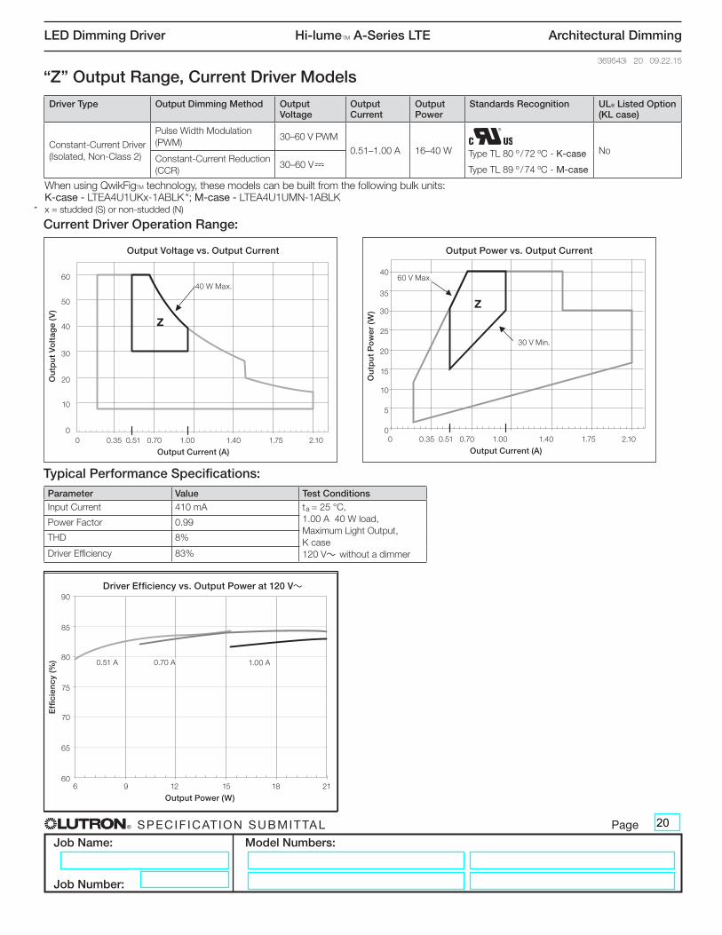
Parameter Value Test ConditionsInput Current 410 mA ta = 25 °C,
1.00 A 40 W load, Maximum Light Output, K case 120 V~ without a dimmer
Power Factor 0.99
THD 8%
Driver Efficiency 83%
Ou
tpu
t P
ow
er (
W)
Output Power vs. Output Current
0 0.35 0.51 0.70 1.00 1.40 1.75 2.10
Output Current (A)
40
35
30
25
20
0
15
10
5
Ou
tpu
t V
olt
age
(V)
60
Output Voltage vs. Output Current
0 0.35 0.51 0.70 1.00 1.40 1.75 2.10
Output Current (A)
50
30
20
10
0
40
“Z” Output Range, Current Driver Models
Output Voltage vs. Output Current
Out
put
Vo
ltag
e (V
)
Output Power vs. Output Current
Out
put
Po
wer
(W)
Output Current (A)
0
10
20
30
40
50
60
0 0.35 0.7 1.4 1.75 2.1
Output Current (A)
0
5
10
15
20
25
30
35
40
0 0.35 0.7 1.4 1.75 2.10.51 1.00 0.51 1.00
Output Power (W)
Effi
cien
cy (%
)
Driver Efficiency vs. Output Power at 277 V~
60
65
70
75
80
85
90
15 20 25 30 35 40
ZZ
Current Driver Operation Range:
Output Voltage vs. Output Current
Out
put
Vo
ltag
e (V
)
Output Power vs. Output Current
Out
put
Po
wer
(W)
Output Current (A)
0
10
20
30
40
50
60
0 0.35 0.7 1.4 1.75 2.1
Output Current (A)
0
5
10
15
20
25
30
35
40
0 0.35 0.7 1.4 1.75 2.10.51 1.00 0.51 1.00
Output Power (W)
Effi
cien
cy (%
)
Driver Efficiency vs. Output Power at 277 V~
60
65
70
75
80
85
90
15 20 25 30 35 40
ZZ
60 V Max.
30 V Min.
40 W Max.
Effi
cien
cy (%
)
90Driver Efficiency vs. Output Power at 120 V~
6 9 12 15 18 21
Output Power (W)
85
80
75
70
65
60
0.70 A0.51 A 1.00 A
When using QwikFigTM technology, these models can be built from the following bulk units: K-case - LTEA4U1UKx-1ABLK *; M-case - LTEA4U1UMN-1ABLK* x = studded (S) or non-studded (N)
Driver Type Output Dimming Method Output Voltage
Output Current
Output Power
Standards Recognition UL® Listed Option (KL case)
Constant-Current Driver (Isolated, Non-Class 2)
Pulse Width Modulation (PWM)
30–60 V PWM
0.51–1.00 A 16–40 W NoConstant-Current Reduction (CCR)
30–60 V-Type TL 80 º / 72 ºC - K-case
Type TL 89 º / 74 ºC - M-case
20

® SPECIF ICAT ION SUBMITTAL Page
Job Name:
Job Number:
Model Numbers:
LED Dimming Driver Hi-lumeT A-Series LTE Architectural Dimming
369543i 21 09.22.15
Bulk Model Driver Type Output Dimming Method Output Voltage Output Current Output Power Standards Recognition
3ABLKConstant-Current Driver (Class 2)
Constant-Current Reduction (CCR)
30–54 V- 0.20–1.00 A 6–40 WType TL 82 º / 74 ºC
Bulk Model Coverage - K-Case Model NumbersFor use with Lutron® QwikFigTM technology
3ABLK Operation Range:
Output Voltage vs. Output Current
Output Current (A)
Out
put
Vo
ltag
e (V
)
Output Power vs. Output Current
Output Current (A)
Out
put
Po
wer
(W)
0
10
20
30
40
50
54
60
0.20 0.50 0.20 0.500
5
10
15
20
25
30
35
40
45
0 0.35 0.70 1.05 1.40 1.75 2.10
60
65
70
75
80
85
90
Output Power (W)
Effi
cien
cy (%
)
Driver Efficiency vs. Output Power at 120 V~
6 9 12 15 18 21 24 2760
65
70
75
80
85
90
Output Power (W)
Effi
cien
cy (%
)
Driver Efficiency vs. Output Power at 277 V~
6 9 12 15 18 21 24 27
0 0.35 0.7 1.41.05 2.1
E
E
0.20 A
0.35 A
0.50 A
0.20 A
0.35 A
0.50 A
F
Ou
tpu
t P
ow
er (
W)
45LED Load Output Range: Constant-Current Drivers E and F
0 0.20 0.35 0.50 0.70 1.00 1.05 1.40 1.75 2.10Output Current (A)
40
35
30
25
20
15
10
5
0
3A = Covers “LED Load Output Range” E and F (CCR dimming only)54 V
Maximum30 V Minimum
21
® SPECIF ICAT ION SUBMITTAL Page
Job Name:
Job Number:
Model Numbers:
LED Dimming Driver Hi-lumeT A-Series LTE Architectural Dimming
369543i 22 09.22.15
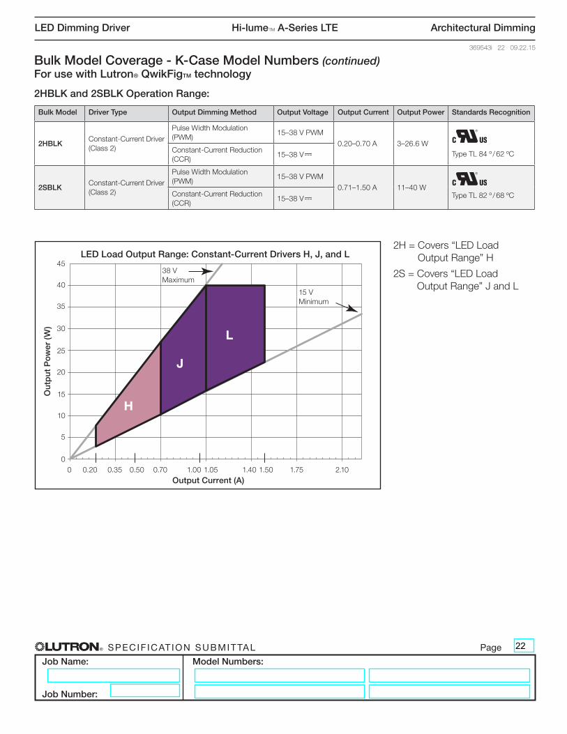
Bulk Model Coverage - K-Case Model Numbers (continued)For use with Lutron® QwikFigTM technology
Output Voltage vs. Output Current
Output Current (A)
Out
put
Vo
ltag
e (V
)
Output Power vs. Output Current
Output Current (A)
Out
put
Po
wer
(W)
0
10
20
30
40
50
54
60
0.20 0.50 0.20 0.500
5
10
15
20
25
30
35
40
45
0 0.35 0.70 1.05 1.40 1.75 2.10
60
65
70
75
80
85
90
Output Power (W)
Effi
cien
cy (%
)
Driver Efficiency vs. Output Power at 120 V~
6 9 12 15 18 21 24 2760
65
70
75
80
85
90
Output Power (W)
Effi
cien
cy (%
)
Driver Efficiency vs. Output Power at 277 V~
6 9 12 15 18 21 24 27
0 0.35 0.7 1.41.05 2.1
E
H
0.20 A
0.35 A
0.50 A
0.20 A
0.35 A
0.50 A
J
L
2HBLK and 2SBLK Operation Range:
Ou
tpu
t P
ow
er (
W)
45LED Load Output Range: Constant-Current Drivers H, J, and L
0 0.20 0.35 0.50 0.70 1.00 1.05 1.40 1.50 1.75 2.10Output Current (A)
40
35
30
25
20
15
10
5
0
Bulk Model Driver Type Output Dimming Method Output Voltage Output Current Output Power Standards Recognition
2HBLKConstant-Current Driver (Class 2)
Pulse Width Modulation (PWM)
15–38 V PWM
0.20–0.70 A 3–26.6 WType TL 84 º / 62 ºC Constant-Current Reduction
(CCR) 15–38 V-
2SBLKConstant-Current Driver (Class 2)
Pulse Width Modulation (PWM)
15–38 V PWM
0.71–1.50 A 11–40 WType TL 82 º / 68 ºC Constant-Current Reduction
(CCR) 15–38 V-
2H = Covers “LED Load Output Range” H
2S = Covers “LED Load Output Range” J and L
38 V Maximum
15 V Minimum
22
® SPECIF ICAT ION SUBMITTAL Page
Job Name:
Job Number:
Model Numbers:
LED Dimming Driver Hi-lumeT A-Series LTE Architectural Dimming
369543i 23 09.22.15
Bulk Model Coverage - K-Case Model Numbers (continued)For use with Lutron® QwikFigTM technology
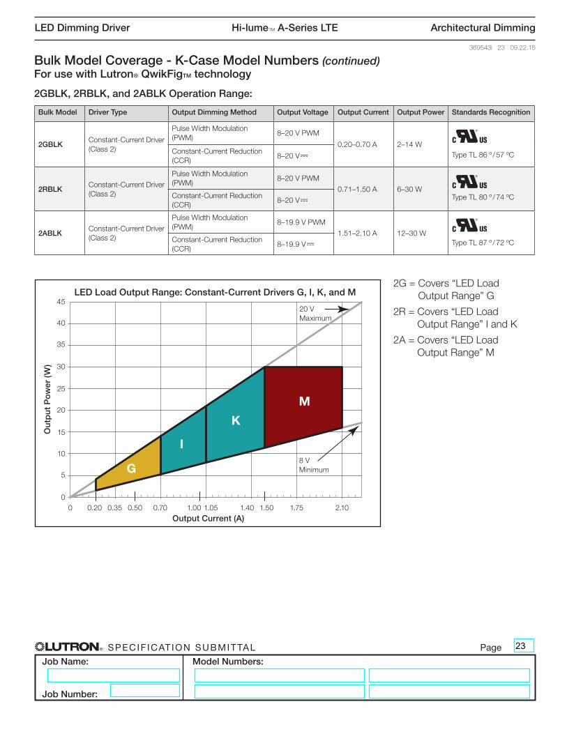
2GBLK, 2RBLK, and 2ABLK Operation Range:
Output Voltage vs. Output Current
Output Current (A)
Out
put
Vo
ltag
e (V
)
Output Power vs. Output Current
Output Current (A)
Out
put
Po
wer
(W)
0
10
20
30
40
50
54
60
0.20 0.50 0.20 0.500
5
10
15
20
25
30
35
40
45
0 0.35 0.70 1.05 1.40 1.75 2.10
60
65
70
75
80
85
90
Output Power (W)
Effi
cien
cy (%
)
Driver Efficiency vs. Output Power at 120 V~
6 9 12 15 18 21 24 2760
65
70
75
80
85
90
Output Power (W)
Effi
cien
cy (%
)
Driver Efficiency vs. Output Power at 277 V~
6 9 12 15 18 21 24 27
0 0.35 0.7 1.41.05 2.1
E
G
0.20 A
0.35 A
0.50 A
0.20 A
0.35 A
0.50 A
I
K
M
Ou
tpu
t P
ow
er (
W)
45LED Load Output Range: Constant-Current Drivers G, I, K, and M
0 0.20 0.35 0.50 0.70 1.00 1.05 1.40 1.50 1.75 2.10Output Current (A)
40
35
30
25
20
15
10
5
0
Bulk Model Driver Type Output Dimming Method Output Voltage Output Current Output Power Standards Recognition
2GBLKConstant-Current Driver (Class 2)
Pulse Width Modulation (PWM)
8–20 V PWM
0.20–0.70 A 2–14 WType TL 86 º / 57 ºC Constant-Current Reduction
(CCR) 8–20 V-
2RBLKConstant-Current Driver (Class 2)
Pulse Width Modulation (PWM)
8–20 V PWM
0.71–1.50 A 6–30 WType TL 80 º / 74 ºC Constant-Current Reduction
(CCR) 8–20 V-
2ABLKConstant-Current Driver (Class 2)
Pulse Width Modulation (PWM)
8–19.9 V PWM
1.51–2.10 A 12–30 WType TL 87 º / 72 ºC Constant-Current Reduction
(CCR) 8–19.9 V-
2G = Covers “LED Load Output Range” G
2R = Covers “LED Load Output Range” I and K
2A = Covers “LED Load Output Range” M
20 V Maximum
8 V Minimum
23
® SPECIF ICAT ION SUBMITTAL Page
Job Name:
Job Number:
Model Numbers:
LED Dimming Driver Hi-lumeT A-Series LTE Architectural Dimming
369543i 24 09.22.15
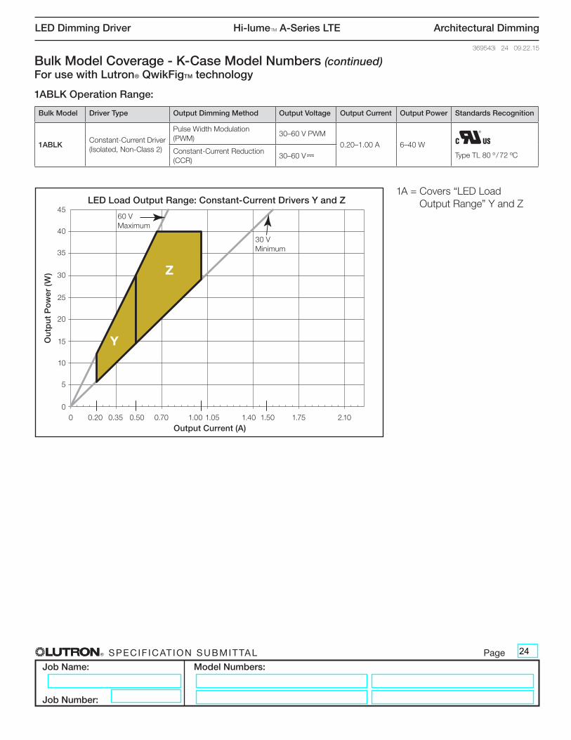
1ABLK Operation Range:
Bulk Model Coverage - K-Case Model Numbers (continued)For use with Lutron® QwikFigTM technology
Output Voltage vs. Output Current
Output Current (A)
Out
put
Vo
ltag
e (V
)
Output Power vs. Output Current
Output Current (A)
Out
put
Po
wer
(W)
0
10
20
30
40
50
54
60
0.20 0.50 0.20 0.500
5
10
15
20
25
30
35
40
45
0 0.35 0.70 1.05 1.40 1.75 2.10
60
65
70
75
80
85
90
Output Power (W)
Effi
cien
cy (%
)
Driver Efficiency vs. Output Power at 120 V~
6 9 12 15 18 21 24 2760
65
70
75
80
85
90
Output Power (W)
Effi
cien
cy (%
)
Driver Efficiency vs. Output Power at 277 V~
6 9 12 15 18 21 24 27
0 0.35 0.7 1.41.05 2.1
E
Y
0.20 A
0.35 A
0.50 A
0.20 A
0.35 A
0.50 A
K
M
Z
Ou
tpu
t P
ow
er (
W)
45LED Load Output Range: Constant-Current Drivers Y and Z
0 0.20 0.35 0.50 0.70 1.00 1.05 1.40 1.50 1.75 2.10Output Current (A)
40
35
30
25
20
15
10
5
0
Bulk Model Driver Type Output Dimming Method Output Voltage Output Current Output Power Standards Recognition
1ABLKConstant-Current Driver (Isolated, Non-Class 2)
Pulse Width Modulation (PWM)
30–60 V PWM
0.20–1.00 A 6–40 WType TL 80 º / 72 ºC Constant-Current Reduction
(CCR) 30–60 V-
1A = Covers “LED Load Output Range” Y and Z
60 V Maximum
30 V Minimum
24
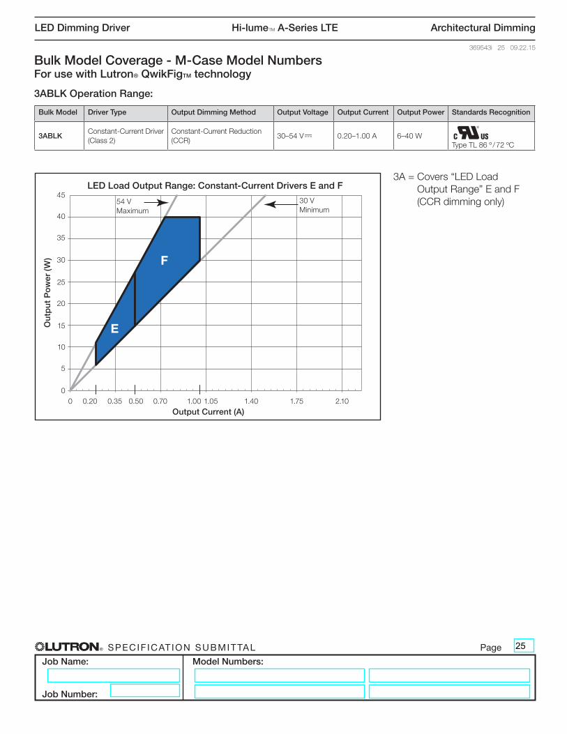
® SPECIF ICAT ION SUBMITTAL Page
Job Name:
Job Number:
Model Numbers:
LED Dimming Driver Hi-lumeT A-Series LTE Architectural Dimming
369543i 25 09.22.15
Bulk Model Coverage - M-Case Model NumbersFor use with Lutron® QwikFigTM technology
3ABLK Operation Range:
Bulk Model Driver Type Output Dimming Method Output Voltage Output Current Output Power Standards Recognition
3ABLKConstant-Current Driver (Class 2)
Constant-Current Reduction (CCR)
30–54 V- 0.20–1.00 A 6–40 WType TL 86 º / 72 ºC
3A = Covers “LED Load Output Range” E and F (CCR dimming only)
Output Voltage vs. Output Current
Output Current (A)
Out
put
Vo
ltag
e (V
)
Output Power vs. Output Current
Output Current (A)
Out
put
Po
wer
(W)
0
10
20
30
40
50
54
60
0.20 0.50 0.20 0.500
5
10
15
20
25
30
35
40
45
0 0.35 0.70 1.05 1.40 1.75 2.10
60
65
70
75
80
85
90
Output Power (W)
Effi
cien
cy (%
)
Driver Efficiency vs. Output Power at 120 V~
6 9 12 15 18 21 24 2760
65
70
75
80
85
90
Output Power (W)
Effi
cien
cy (%
)
Driver Efficiency vs. Output Power at 277 V~
6 9 12 15 18 21 24 27
0 0.35 0.7 1.41.05 2.1
E
E
0.20 A
0.35 A
0.50 A
0.20 A
0.35 A
0.50 A
F
Ou
tpu
t P
ow
er (
W)
45LED Load Output Range: Constant-Current Drivers E and F
0 0.20 0.35 0.50 0.70 1.00 1.05 1.40 1.75 2.10Output Current (A)
40
35
30
25
20
15
10
5
0
54 V Maximum
30 V Minimum
25
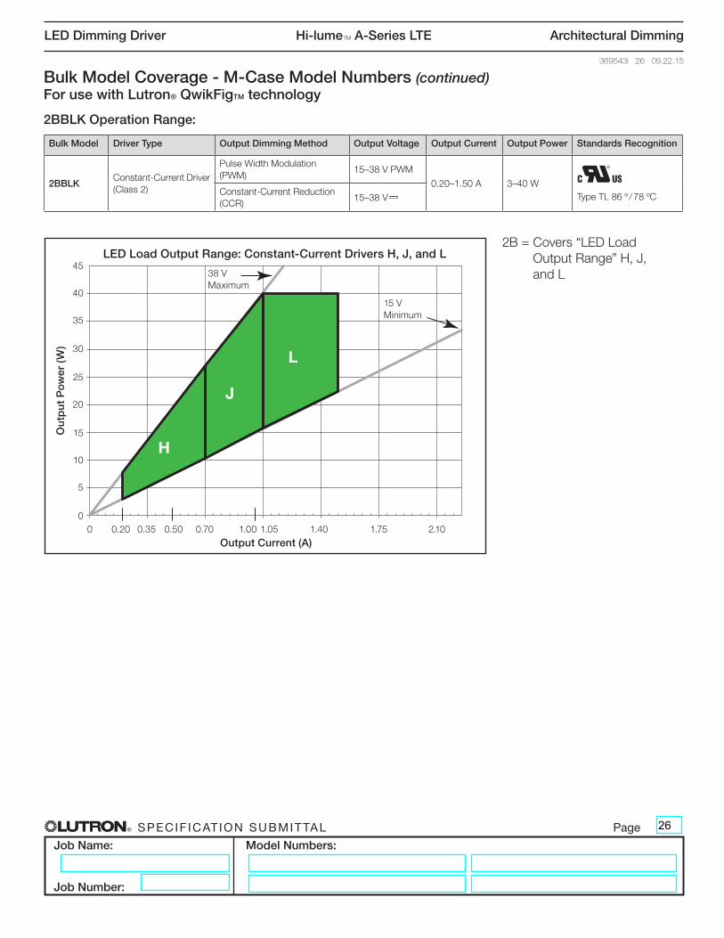
® SPECIF ICAT ION SUBMITTAL Page
Job Name:
Job Number:
Model Numbers:
LED Dimming Driver Hi-lumeT A-Series LTE Architectural Dimming
369543i 26 09.22.15
2BBLK Operation Range:
Bulk Model Coverage - M-Case Model Numbers (continued)For use with Lutron® QwikFigTM technology
Bulk Model Driver Type Output Dimming Method Output Voltage Output Current Output Power Standards Recognition
2BBLKConstant-Current Driver (Class 2)
Pulse Width Modulation (PWM)
15–38 V PWM
0.20–1.50 A 3–40 WType TL 86 º / 78 ºC Constant-Current Reduction
(CCR) 15–38 V-
Output Voltage vs. Output Current
Output Current (A)
Out
put
Vo
ltag
e (V
)
Output Power vs. Output Current
Output Current (A)
Out
put
Po
wer
(W)
0
10
20
30
40
50
54
60
0.20 0.50 0.20 0.500
5
10
15
20
25
30
35
40
45
0 0.35 0.70 1.05 1.40 1.75 2.10
60
65
70
75
80
85
90
Output Power (W)
Effi
cien
cy (%
)
Driver Efficiency vs. Output Power at 120 V~
6 9 12 15 18 21 24 2760
65
70
75
80
85
90
Output Power (W)
Effi
cien
cy (%
)
Driver Efficiency vs. Output Power at 277 V~
6 9 12 15 18 21 24 27
0 0.35 0.7 1.41.05 2.1
E
H
0.20 A
0.35 A
0.50 A
0.20 A
0.35 A
0.50 A
J
L
Ou
tpu
t P
ow
er (
W)
45LED Load Output Range: Constant-Current Drivers H, J, and L
0 0.20 0.35 0.50 0.70 1.00 1.05 1.40 1.75 2.10Output Current (A)
40
35
30
25
20
15
10
5
0
2B = Covers “LED Load Output Range” H, J, and L38 V
Maximum
15 V Minimum
26
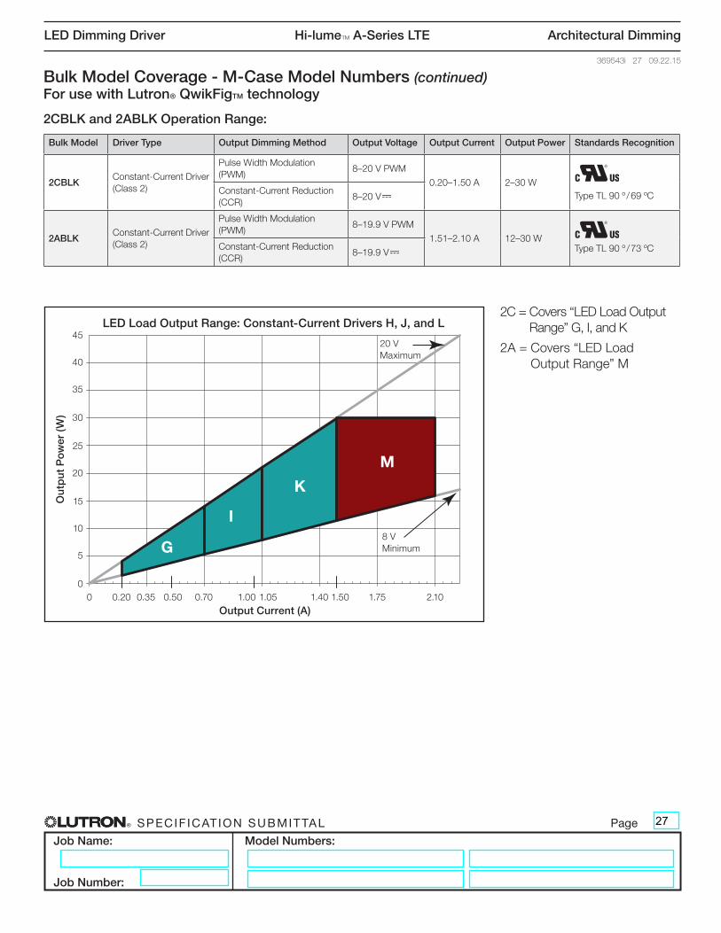
® SPECIF ICAT ION SUBMITTAL Page
Job Name:
Job Number:
Model Numbers:
LED Dimming Driver Hi-lumeT A-Series LTE Architectural Dimming
369543i 27 09.22.15
Bulk Model Coverage - M-Case Model Numbers (continued)For use with Lutron® QwikFigTM technology
2CBLK and 2ABLK Operation Range:
Output Voltage vs. Output Current
Output Current (A)
Out
put
Vo
ltag
e (V
)
Output Power vs. Output Current
Output Current (A)
Out
put
Po
wer
(W)
0
10
20
30
40
50
54
60
0.20 0.50 0.20 0.500
5
10
15
20
25
30
35
40
45
0 0.35 0.70 1.05 1.40 1.75 2.10
60
65
70
75
80
85
90
Output Power (W)
Effi
cien
cy (%
)
Driver Efficiency vs. Output Power at 120 V~
6 9 12 15 18 21 24 2760
65
70
75
80
85
90
Output Power (W)
Effi
cien
cy (%
)
Driver Efficiency vs. Output Power at 277 V~
6 9 12 15 18 21 24 27
0 0.35 0.7 1.41.05 2.1
E
G
0.20 A
0.35 A
0.50 A
0.20 A
0.35 A
0.50 A
I
K
M
Ou
tpu
t P
ow
er (
W)
45LED Load Output Range: Constant-Current Drivers H, J, and L
0 0.20 0.35 0.50 0.70 1.00 1.05 1.40 1.50 1.75 2.10Output Current (A)
40
35
30
25
20
15
10
5
0
Bulk Model Driver Type Output Dimming Method Output Voltage Output Current Output Power Standards Recognition
2CBLKConstant-Current Driver (Class 2)
Pulse Width Modulation (PWM)
8–20 V PWM
0.20–1.50 A 2–30 WType TL 90 º / 69 ºC Constant-Current Reduction
(CCR) 8–20 V-
2ABLKConstant-Current Driver (Class 2)
Pulse Width Modulation (PWM)
8–19.9 V PWM
1.51–2.10 A 12–30 WType TL 90 º / 73 ºC Constant-Current Reduction
(CCR) 8–19.9 V-
2C = Covers “LED Load Output Range” G, I, and K
2A = Covers “LED Load Output Range” M
20 V Maximum
8 V Minimum
27

® SPECIF ICAT ION SUBMITTAL Page
Job Name:
Job Number:
Model Numbers:
LED Dimming Driver Hi-lumeT A-Series LTE Architectural Dimming
369543i 28 09.22.15
1ABLK Operation Range:
Bulk Model Coverage - M-Case Model Numbers (continued)For use with Lutron® QwikFigTM technology
Bulk Model Driver Type Output Dimming Method Output Voltage Output Current Output Power Standards Recognition
1ABLKConstant-Current Driver (Isolated, Non-Class 2)
Pulse Width Modulation (PWM)
30–60 V PWM
0.20–1.00 A 6–40 WType TL 89 º / 74 ºC Constant-Current Reduction
(CCR) 30–60 V-
Output Voltage vs. Output Current
Output Current (A)
Out
put
Vo
ltag
e (V
)
Output Power vs. Output Current
Output Current (A)
Out
put
Po
wer
(W)
0
10
20
30
40
50
54
60
0.20 0.50 0.20 0.500
5
10
15
20
25
30
35
40
45
0 0.35 0.70 1.05 1.40 1.75 2.10
60
65
70
75
80
85
90
Output Power (W)
Effi
cien
cy (%
)
Driver Efficiency vs. Output Power at 120 V~
6 9 12 15 18 21 24 2760
65
70
75
80
85
90
Output Power (W)
Effi
cien
cy (%
)
Driver Efficiency vs. Output Power at 277 V~
6 9 12 15 18 21 24 27
0 0.35 0.7 1.41.05 2.1
E
Y
0.20 A
0.35 A
0.50 A
0.20 A
0.35 A
0.50 A
K
M
Z
Ou
tpu
t P
ow
er (
W)
45LED Load Output Range: Constant-Current Drivers Y and Z
0 0.20 0.35 0.50 0.70 1.00 1.05 1.40 1.50 1.75 2.10Output Current (A)
40
35
30
25
20
15
10
5
0
1A = Covers “LED Load Output Range” Y and Z
60 V Maximum
30 V Minimum
28
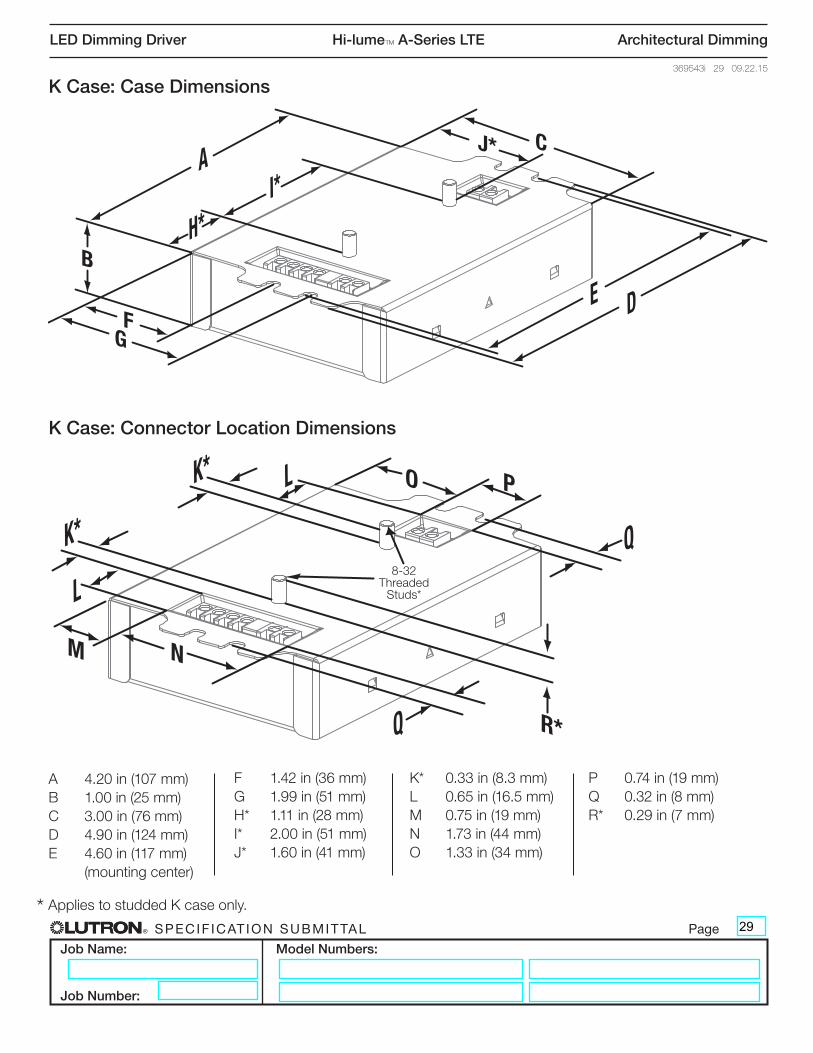
® SPECIF ICAT ION SUBMITTAL Page
Job Name:
Job Number:
Model Numbers:
LED Dimming Driver Hi-lumeT A-Series LTE Architectural Dimming
369543i 29 09.22.15
K Case: Case Dimensions
K Case: Connector Location Dimensions
B
FG
J* C
H*
A
E D
I*
M N
O P
R*
K*
Q
L
K*
Q
L
A 4.20 in (107 mm)B 1.00 in (25 mm)C 3.00 in (76 mm)D 4.90 in (124 mm)E 4.60 in (117 mm) (mounting center)
F 1.42 in (36 mm)G 1.99 in (51 mm)H* 1.11 in (28 mm)I* 2.00 in (51 mm)J* 1.60 in (41 mm)
K* 0.33 in (8.3 mm)L 0.65 in (16.5 mm)M 0.75 in (19 mm)N 1.73 in (44 mm)O 1.33 in (34 mm)
* Applies to studded K case only.
8-32 Threaded
Studs*
P 0.74 in (19 mm)Q 0.32 in (8 mm)R* 0.29 in (7 mm)
29
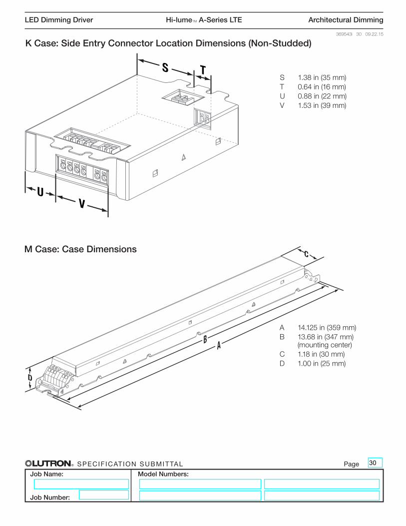
® SPECIF ICAT ION SUBMITTAL Page
Job Name:
Job Number:
Model Numbers:
LED Dimming Driver Hi-lumeT A-Series LTE Architectural Dimming
369543i 30 09.22.15
D
C
B A
M Case: Case Dimensions
A 14.125 in (359 mm)B 13.68 in (347 mm) (mounting center)C 1.18 in (30 mm)D 1.00 in (25 mm)
K Case: Side Entry Connector Location Dimensions (Non-Studded)
S
UV
TS 1.38 in (35 mm)T 0.64 in (16 mm)U 0.88 in (22 mm)V 1.53 in (39 mm)
30
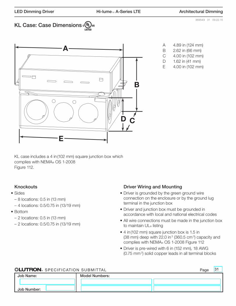
® SPECIF ICAT ION SUBMITTAL Page
Job Name:
Job Number:
Model Numbers:
LED Dimming Driver Hi-lumeT A-Series LTE Architectural Dimming
369543i 31 09.22.15
KL Case: Case Dimensions
KL case includes a 4 in (102 mm) square junction box which complies with NEMA® OS 1-2008 Figure 112.
A
B
CD
E
A 4.89 in (124 mm)B 2.62 in (66 mm)C 4.00 in (102 mm)D 1.62 in (41 mm)E 4.00 in (102 mm)
Knockouts• Sides
– 8 locations: 0.5 in (13 mm)– 4 locations: 0.5/0.75 in (13/19 mm)
• Bottom– 2 locations: 0.5 in (13 mm)– 2 locations: 0.5/0.75 in (13/19 mm)
Driver Wiring and Mounting• Driver is grounded by the green ground wire
connection on the enclosure or by the ground lug terminal in the junction box
• Driver and junction box must be grounded in accordance with local and national electrical codes
• All wire connections must be made in the junction box to maintain UL® listing
• 4 in (102 mm) square junction box is 1.5 in (38 mm) deep with 22.0 in 3 (360.5 cm 3) capacity and complies with NEMA® OS 1-2008 Figure 112
• Driver is pre-wired with 6 in (152 mm), 18 AWG (0.75 mm 2) solid copper leads in all terminal blocks
31
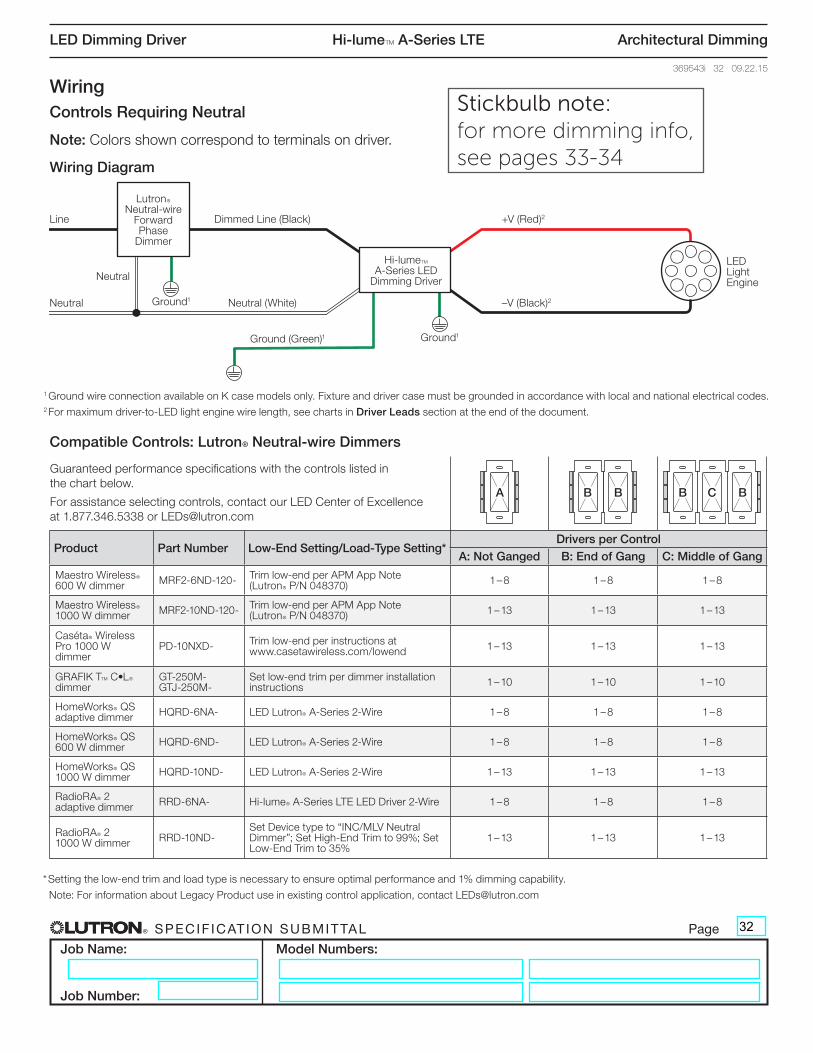
® SPECIF ICAT ION SUBMITTAL Page
Job Name:
Job Number:
Model Numbers:
LED Dimming Driver Hi-lumeT A-Series LTE Architectural Dimming
369543i 32 09.22.15
WiringControls Requiring Neutral
Note: Colors shown correspond to terminals on driver.
Wiring Diagram
1 Ground wire connection available on K case models only. Fixture and driver case must be grounded in accordance with local and national electrical codes.2 For maximum driver-to-LED light engine wire length, see charts in Driver Leads section at the end of the document.
Compatible Controls: Lutron® Neutral-wire Dimmers
Guaranteed performance specifications with the controls listed in the chart below.
For assistance selecting controls, contact our LED Center of Excellence at 1.877.346.5338 or [email protected]
Product Part Number Low-End Setting/Load-Type Setting*Drivers per Control
A: Not Ganged B: End of Gang C: Middle of Gang
Maestro WirelessR 600 W dimmer MRF2-6ND-120- Trim low-end per APM App Note
(LutronR P/N 048370) 1 – 8 1 – 8 1 – 8
Maestro WirelessR 1000 W dimmer MRF2-10ND-120- Trim low-end per APM App Note
(LutronR P/N 048370) 1 – 13 1 – 13 1 – 13
CasétaR Wireless Pro 1000 W dimmer
PD-10NXD- Trim low-end per instructions at www.casetawireless.com/lowend 1 – 13 1 – 13 1 – 13
GRAFIK TT C)LR dimmer
GT-250M- GTJ-250M-
Set low-end trim per dimmer installation instructions 1 – 10 1 – 10 1 – 10
HomeWorksR QS adaptive dimmer HQRD-6NA- LED LutronR A-Series 2-Wire 1 – 8 1 – 8 1 – 8
HomeWorksR QS 600 W dimmer HQRD-6ND- LED LutronR A-Series 2-Wire 1 – 8 1 – 8 1 – 8
HomeWorksR QS 1000 W dimmer HQRD-10ND- LED LutronR A-Series 2-Wire 1 – 13 1 – 13 1 – 13
RadioRAR 2 adaptive dimmer RRD-6NA- Hi-lumeR A-Series LTE LED Driver 2-Wire 1 – 8 1 – 8 1 – 8
RadioRAR 2 1000 W dimmer RRD-10ND-
Set Device type to “INC/MLV Neutral Dimmer”; Set High-End Trim to 99%; Set Low-End Trim to 35%
1 – 13 1 – 13 1 – 13
A B B B C B
LutronR Neutral-wire
Forward Phase
Dimmer
Hi-lumeT A-Series LED
Dimming Driver
LED Light Engine
Dimmed Line (Black)Line +V (Red)2
–V (Black)2Neutral (White)
Neutral
Neutral
Ground1
Ground1
Ground (Green)1
* Setting the low-end trim and load type is necessary to ensure optimal performance and 1% dimming capability.
Note: For information about Legacy Product use in existing control application, contact [email protected]
32
Stickbulb note: for more dimming info, see pages 33-34
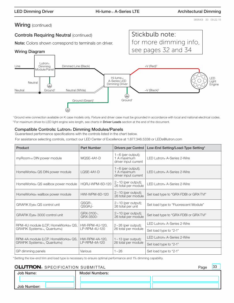
® SPECIF ICAT ION SUBMITTAL Page
Job Name:
Job Number:
Model Numbers:
LED Dimming Driver Hi-lumeT A-Series LTE Architectural Dimming
369543i 33 09.22.15
Wiring (continued)
Controls Requiring Neutral (continued)
Note: Colors shown correspond to terminals on driver.
Wiring Diagram
1 Ground wire connection available on K case models only. Fixture and driver case must be grounded in accordance with local and national electrical codes.2 For maximum driver-to-LED light engine wire length, see charts in Driver Leads section at the end of the document.
Compatible Controls: Lutron® Dimming Modules/PanelsGuaranteed performance specifications with the controls listed in the chart below.
For assistance selecting controls, contact our LED Center of Excellence at 1.877.346.5338 or [email protected]
Product Part Number Drivers per Control Low-End Setting/Load-Type Setting*
myRoomTM DIN power module MQSE-4A1-D1 – 6 (per output); 1 A maximum driver input current
LED Lutron® A-Series 2-Wire
HomeWorks® QS DIN power module LQSE-4A1-D1 – 6 (per output); 1 A maximum driver input current
LED Lutron® A-Series 2-Wire
HomeWorks® QS wallbox power module HQRJ-WPM-6D-120 2 – 10 (per output); 26 total per module LED Lutron® A-Series 2-Wire
HomeWorks® wallbox power module HWI-WPM-6D-120 2 – 10 (per output); 26 total per module Set load type to “GRX-FDBI or GRX-TVI”
GRAFIK Eye® QS control unit QSGR-, QSGRJ-
2 – 10 (per output); 26 total per unit Set load type to “Fluorescent Module”
GRAFIK Eye® 3000 control unit GRX-3100-, GRX-3500-
2 – 10 (per output); 26 total per module Set load type to “GRX-FDBI or GRX-TVI”
RPM-4U module (LCP, HomeWorks® QS, GRAFIK SystemsTM, Quantum®)
HW-RPM-4U-120, LP-RPM-4U-120
2 – 26 (per output); 26 total per module
LED Lutron® A-Series 2-Wire
Set load type to “2-1”
RPM-4A module (LCP, HomeWorks® QS, GRAFIK SystemsTM, Quantum®)
HW-RPM-4A-120, LP-RPM-4A-120
1 – 13 (per output); 26 total per module
LED Lutron® A-Series 2-Wire
Set load type to “2-1”
GP dimming panels Various 1 – 26 Set load type to “2-1”
* Setting the low-end trim and load type is necessary to ensure optimal performance and 1% dimming capability.
LutronR Dimming
Module/Panel
Hi-lumeT A-Series LED
Dimming Driver
LED Light Engine
Dimmed Line (Black)Line +V (Red)2
–V (Black)2Neutral (White)
Neutral
Neutral
Ground1
Ground1
Ground (Green)1
33
Stickbulb note: for more dimming info, see pages 32 and 34
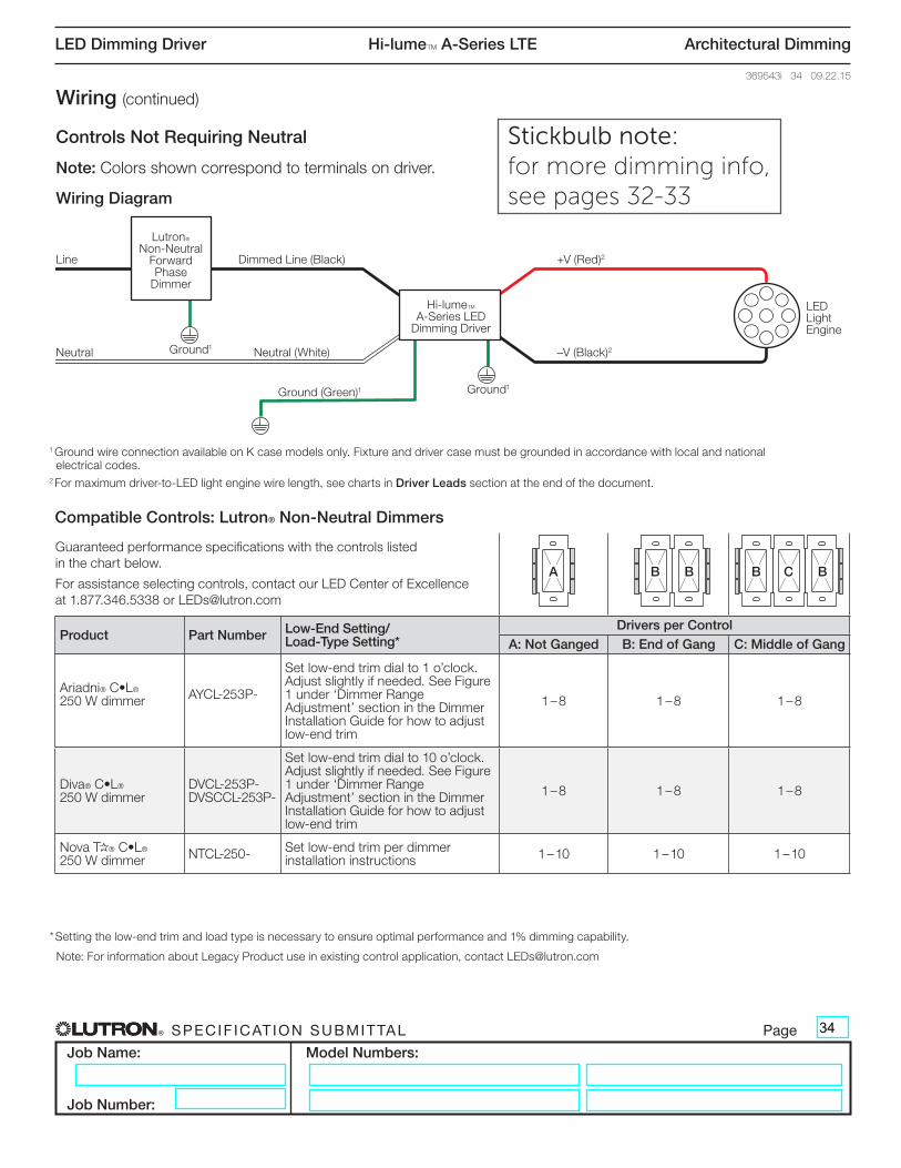
® SPECIF ICAT ION SUBMITTAL Page
Job Name:
Job Number:
Model Numbers:
LED Dimming Driver Hi-lumeT A-Series LTE Architectural Dimming
369543i 34 09.22.15
Wiring (continued)
Controls Not Requiring Neutral
Note: Colors shown correspond to terminals on driver.
Wiring Diagram
1 Ground wire connection available on K case models only. Fixture and driver case must be grounded in accordance with local and national electrical codes.
2 For maximum driver-to-LED light engine wire length, see charts in Driver Leads section at the end of the document.
LutronR Non-Neutral
Forward Phase
Dimmer
Hi-lumeT A-Series LED
Dimming Driver
LED Light Engine
Dimmed Line (Black)Line +V (Red)2
–V (Black)2Neutral (White)Neutral
Ground1
Ground1
Ground (Green)1
Compatible Controls: Lutron® Non-Neutral Dimmers
Guaranteed performance specifications with the controls listed in the chart below.
For assistance selecting controls, contact our LED Center of Excellence at 1.877.346.5338 or [email protected]
Product Part Number Low-End Setting/ Load-Type Setting*
Drivers per ControlA: Not Ganged B: End of Gang C: Middle of Gang
Ariadni® C•L® 250 W dimmer AYCL-253P-
Set low-end trim dial to 1 o’clock. Adjust slightly if needed. See Figure 1 under ‘Dimmer Range Adjustment’ section in the Dimmer Installation Guide for how to adjust low-end trim
1 – 8 1 – 8 1 – 8
Diva® C•L® 250 W dimmer
DVCL-253P- DVSCCL-253P-
Set low-end trim dial to 10 o’clock. Adjust slightly if needed. See Figure 1 under ‘Dimmer Range Adjustment’ section in the Dimmer Installation Guide for how to adjust low-end trim
1 – 8 1 – 8 1 – 8
Nova T*® C•L® 250 W dimmer NTCL-250- Set low-end trim per dimmer
installation instructions 1 – 10 1 – 10 1 – 10
A B B B C B
* Setting the low-end trim and load type is necessary to ensure optimal performance and 1% dimming capability.
Note: For information about Legacy Product use in existing control application, contact [email protected]
34
Stickbulb note: for more dimming info, see pages 32-33
® SPECIF ICAT ION SUBMITTAL Page
Job Name:
Job Number:
Model Numbers:
LED Dimming Driver Hi-lumeT A-Series LTE Architectural Dimming
369543i 35 09.22.15
ELECTRICIANS AND CONTRACTORS
Driver Leads
Maximum driver-to-LED light engine wire length for Constant-Current Drivers:
Maximum driver-to-LED light engine wire length for Constant-Voltage Drivers:
Wiring and Grounding
Driver and lighting fixture must be grounded. Drivers must be installed per national and local electrical codes.
LED Load Replacement
For Class 2 rated drivers, the LED load can be changed while the driver is installed and powered.
Maximum Driver Operating Temperature
Driver case temperature (tc) must not exceed UL® conditions of acceptability in end product.
For 50,000 hour lifetime, driver case temperature (tc)must not exceed 65 °C.
FACILITIES MANAGERS
SERVICE
Warranty
For warranty information, please visit www.lutron.com/BallastDriverWarranty.pdf
Replacement Parts
When ordering Lutron® replacement parts please provide the full model number. Consult Lutron® Technical Support if you have any questions.
Further Information
For further information, please visit us at www.lutron.com/hilumeLED or contact our LED Control Center of Excellence at 1.877.346.5338 or [email protected]
Wire GaugeMaximum Lead Length
200 mA to 700 mA
710 mA to 1.50 A
1.51 A to 2.10 A
18 AWG (0.75 mm2) 30 ft (9 m) 15 ft (4.5 m) 10 ft (3 m)
16 AWG (1.5 mm2) 35 ft (10.5 m) 25 ft (7.5 m) 15 ft (4.5 m)
14 AWG (2.5 mm2) 50 ft (15 m) 40 ft (12 m) 25 ft (7.5 m)
12 AWG (4.0 mm2) 100 ft (30 m) 60 ft (18 m) 40 ft (12 m)
Wire GaugeMaximum Lead Length
10 to 20 V- 20.5 to 40 V- 40.5 to 60 V-
18 AWG (0.75 mm2) 10 ft (3 m) 15 ft (4.5 m) 30 ft (9 m)
16 AWG (1.5 mm2) 15 ft (4.5 m) 25 ft (7.5 m) 50 ft (15 m)
14 AWG (2.5 mm2) 25 ft (7.5 m) 40 ft (12 m) 75 ft (22.5 m)
12 AWG (4.0 mm2) 40 ft (12 m) 60 ft (18 m) 100 ft (30 m)
35