Embed Size (px)
Citation preview

Use of functionally graded material layers in a
two-layered pressure vessel
E. Carrera∗, M. SoaveDepartment of Aeronautics and Space Engineering
Politecnico di Torino, Italy
PAPER REF: PVT -09-1198
VERSION ACCEPTED ON NOV 23rd 2010.
Abstract
This work explores the possibilities of using functionally graded material layers to reduce normal andshear stress gradients due to internal pressure and thermal loadings at the interface of a two layeredwall pressure vessel. The two walls are made of an internal thin metallic layer (Titanium, used as aliner to avoid a chemical/physical reaction between the gas and the external layer) and an external thicklayer (carbon fiber used as a structural restraint). Two main geometrical elements are investigated: acylindrical shell and a spherical panel. The Shell analysis has been made by referring to mixed layer-wisetheories which lead to a three-dimensional description of the stress/strain fields in the thickness shelldirection; results related to first order shear deformation theory are given for comparison purposes. Ithas been concluded that it is convenient to use FGM layers to reduce shear and normal stress gradientsat the interfaces. Furthermore, the FGM layers lead to benefits as far as buckling load is concerned;lower values of in-plane shear and longitudinal compressive stress are in fact obtained with respect to apure two-layered wall.
∗Author for correspondence: Erasmo Carrera, Professor. Department of Aeronautics and Space Engineering, Politec-nico di Torino, Corso Duca degli Abruzzi, 24, 10129 Torino, ITALY, tel: +39.011.090.6836, fax: +39.011.564.6899. e.mail:[email protected].
1
1 Introduction
Pressure vessels are defined as containers with a pressure differential between the inside and outside;the inside pressure is usually higher than the outside one, except in some cases such as in submarineapplications. Tanks, vessels and pipelines that carry, store and receive fluids are called pressure vessels.High pressure is often combined with high temperature, flammable fluids or radioactive materials;because of these hazards, it is mandatory that the design be such that no leakage can occur. In addition,these vessels have to be designed carefully to cope with the operating temperature and pressure. Plantsafety and integrity are of fundamental concern in pressure vessel design and these, of course, dependon the adequacy of the design code.The size and geometric form of pressure vessels vary greatly from the large cylindrical vessels used forhigh pressure gas storage to the small sized ones, used as hydraulics units for aircraft, see the recentbook by Chattopadadhyay [1]. Pressure vessels are usually spherical or cylindrical with dome ends.Safety is the main concern in many applications, such as in nuclear power plants. The possible risk ofa given mode of failure and its consequences are balanced against the effort required for its prevention;the resulting design should achieve an adequate standard of safety at a minimum cost. The designfactor used in the ASME Pressure Vessel Code is intended to account for unknown factors associatedwith the design and construction of the equipment; interesting discussion on the use of ASME pressurevessels code for various applications is given in [1].
In recent years, many works on pressure vessels have been published, due to the possibility of theiruse in engineering applications. An important contribution to the study of pressure vessels for spaceapplications was has been made by Bushnell. In the book [2], in fact, the theoretical study is supportedby BOSOR computer application (acronym for Buckling of shells of revolution) that allowed, alreadyback in those years, a study to be made of computer-pressure vessels through different types of analysis:nonlinear static analysis, the study of buckling and vibration. More recently, Zhang et al. in [3] andin [4] have studied spherical tanks which were built using the integral hydro-bulge forming technologyin China in 1992. In these works, a three-dimensional elasto-plastic finite element method is used toanalyse the hydro-bulging process of the tank: the deformation process and the deformation featureshave been revealed, and the stress and strain distributions have been analyzed. Baum in [5] shows that,when there is a circumferential fracture of a cylindrical pressure vessel containing high-pressure gas,the internal pressure falls as gas escapes through the developing breach. If the break is adjacent to theend-cap, the end-cap will be accelerated by the escaping gas. Khan and Uddin in [6] have studied theinstability under pressure of conical end caps with spherical tips when used as end closures to pressurevessels. The results show that the critical pressure for the end closure decreases with increasing apexangle. A numerical analysis study using the finite element method has been carried out by Tafreshi in[7] to investigate the design sensitivity of thin torispherical end pressure vessels. The buckling pressureand stresses in a series of torispherical ends have been evaluated to show the effect of variations inthe shape parameters in these ends. Mackerle in [8], [9] and [10] gives a review on finite elementmethods(FEMs) applied for the analysis of pressure vessel structures, components and piping, from thetheoretical and practical points of view. Another topic of particular interest is the welding procedureregarding pressure vessels. Li and Gobbi in [11] describe potential applications of high-power CO,and Nd lasers to create lightweight structures in the automotive, aeronautic and aerospace industries.The purposes of the research were to examine the possibility of assembling lightweight structures withminimal deformation, reducing the total weight by combining current laser-welding techniques withparticular structural designs, and improving properties and performance. Teng and Lin in [12] havepresented an innovative technique for the fabrication of small models of large steel cylindrical shellsconstructed with many welded panels. The experimental set-ups used to implement this technique inthe laboratory are also described.
Among the most recent applications, pressure vessels with very high pressure for space applications
2
are of interest. These high pressure tanks can be used to store propellent for satellites and space vehicles.Applications could also consider hydrogen storage in the automotive industry in the framework of greencar projects. Considerations on weight, see also Sec. 4.2, clearly show the advantage of using carbon-fibers. A carbon fiber wall is build by employing a filament winding technique. This technique is basedon using a liner on which fibers are wrapped. These fibers are made of durable material which forms themain structure of the vessel. Jones et al. in [13] have described a filament winding process that resultsin a constant thickness lay-out of composite over the end closures of a dome-ended cylindrical vessel. Anexperimental design investigation of manufacturing and design variables that affect composite vesselquality, strength, and stiffness has been conducted by Cohen in [14]. The material and processingvariables were divided into five categories: (a) resin, (b) fiber, (c) fabrication process, (d) design,and (e) equipment. A statistical analysis of the data has shown that the composite vessel strength isaffected by the manufacturing and design variables. Cohen et al. in [15] have offered a continuationof the previous research which included a design of an experiment investigation of manufacturing anddesign variables that affect composite vessel quality and strength.
Unfortunately, carbon fiber cannot be in contact with the gasses, such as helium and hydrogen,which are used in these high pressure tanks. A liner must therefore be used to avoid contact. Theliner therefore has a double aim: to wrap the carbon fibers in the filament winding technique and toseparate the liquified gas from the carbon. The thickness of the liner is obviously much lower than thatof the main structure,in order to exploit the chemical and physical properties without burdening theoverall weight of the structure. The choice of material for the liner is mainly influenced by the type offluid that the vessel must contain. In order to avoid corrosion problems it is important to use metalsthat are compatible with the gas and at the same time present weldability characteristics to satisfythe structural requirements. The discontinuity at the interfaces between the layers leads to additionalcomplications. For instance, in the case of filament winding, the presence of an adhesive could createmechanical problems for the whole structure. The choice for the liner often falls on Titanium as becauseof its high resistance to corrosion.This paper aims to contribute to the design and analysis of composite made pressure vessels with metal-lic thin layers liner. In order to reduce/remove discontinuities at the interface between the Titanium andCarbon fiber, the present work explores the possibilities of using functionally graded material (FGM)layers as interface between liner and composite made structural restraint. FGM consists of material,mostly panels and shells, in which the mechanical/thermal properties varies along the thickness direc-tions. In most case FGM panels are made by using a large number of thin layer with almost continuousvariation of mechanical properties in the thickness direction [16], [17]. Such a feature permits to reducemechanical discontinuity between layers of different materials (as it is in the sandwich structures andin the pressure vessels which are of interest for this work) and related interlaminar stress fields can bestrongly modified. Applications of FGM are also considered to build the walls of engine chambers orrocket nozzles which require high-temperature resistant materials (see [18]). A recent review on FGM,including applications and modeling is given in the review article [19]. FGM are in this work usedbetween Titanium and carbon fibers. A continuous variation of the Young Modulus is assigned fromthat of Titanium to that of the carbon fibers. For sake of simplicity the attention has been restrictedonly to representative structural components. More complex analysis could be considered by futurework. Two main pressure vessel components are considered: a cylindrical shell and a spherical cap.A layer wise mixed shell theory has been employed to handle the continuous variation of mechanicalproperties in the thickness direction in appropriate manner. Results related to the shear deformationtheories that are usually provided by the FE-shell commercial codes are considered for comparisonpurposes. Mechanical and thermal loadings are considered. Stress and displacements are compared inmost of the conducted analysis. The results are restricted to those cases for which Navier type closedform solutions are available. It holds only for harmonic distribution of loading which could be combinedto give constant pressure. That would not lead to changes in the paper conclusions.
3
2 Pressure vessels geometry
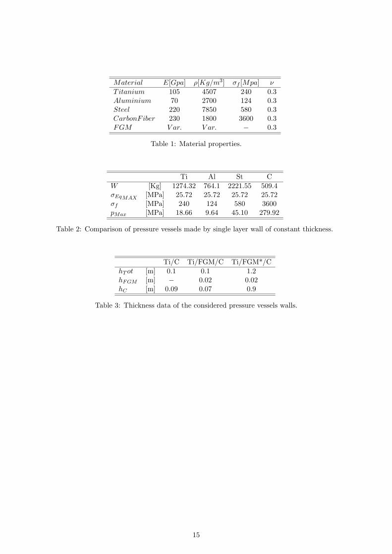
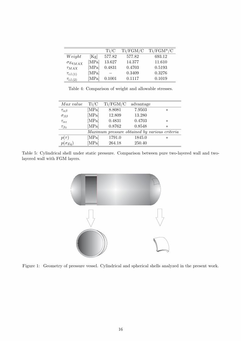
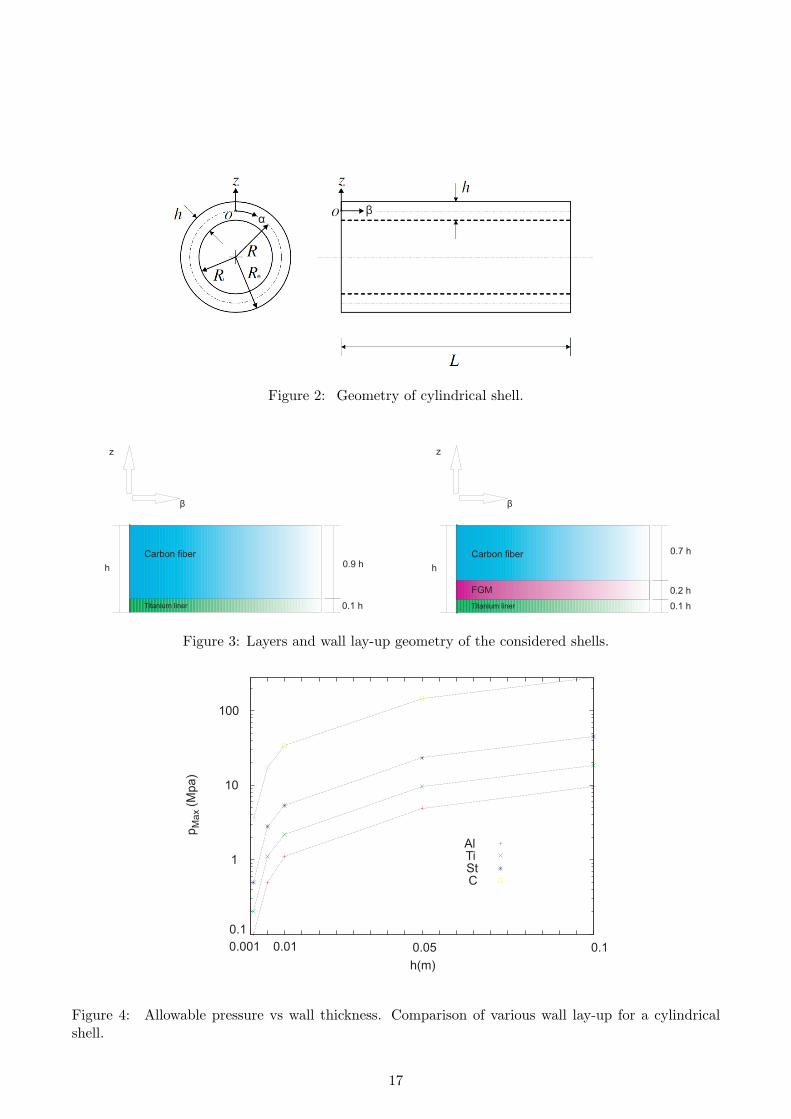
Cylindrical vessels with spherical end caps are considered in this works. Only two significant geometricalparts of the full vessels are treated. These two elements refer to a cylindrical shell (ring) and to aspherical panel taken from the caps, see Figure 1. Authors believe that the conclusion reached in thepresent work are not affected by shell geometries. On the other hand, closed form solutions can beeasily found only for the above mentioned shell elements.Shells radii are denoted by Rα and Rβ along the two in-plane directions α and β respectively; curvilinearreference system (α, β, z) for shells is indicated in Figure 2 where the ring geometry is given. For thecylindrical shell α coincides with the circumferential coordinate and the external and internal radiusof cylinder Re and Ri are defined; β is the longitudinal direction along with the length L is defined.Wall lay-up geometries is given in Figure 3; the flat case related to the longitudinal direction of thecylinder has been drawn, cylindrical and shell geometries should be considered in the other cases. Thetwo cases under analysis are described: the original two-layered wall (titanium, carbon fiber) is on theleft side while the wall including a functionally graded material layer is on the right side.
3 Classical and layer-wise mixed used shell theories
Shell analysis is herein conducted by employing the Carrera Unified Formulation (CUF) [20], [21], [22].Quasi three-dimensional description of stress states in the layer is acquired upon application of a layer-wise mixed shell theories with quartic-ordered of expansion for both displacements and transverse stressvariables in the shell thickness directions. The most known and applied First order Shear Deformationshell theories FSDT, is also considered for comparison purposes. Details of CUF can be found in theabove mentioned first authors articles, further application to FGM structures have been more recentlygiven in [24], [25]. Few details of the two referred shell theories are given below.Transverse shear deformations theory, FSDT, introduced according to Reissner and Mindlin’s kinematicassumptions leads to the following displacement fields:
uτ (α, β, z) = u0τ (α, β) + z u1τ (α, β) with τ = α, β, zuz(α, β, z) = u0z(α, β).
(1)
where u are the displacements along α, β and z coordinates, u0 denotes the displacements value incorrespondence to the reference surface Ω and u1 is the first derivative of u0 along the in-plane coor-dinates α and β. Transverse shear stresses computed by FSDT shows “a priori” constant piece-wisedistribution.Layerwise multilayered shells theories refer to kinematics assumptions which are independent in eachlayer k. According to [23] these approaches are herein stated as Layer-Wise (LW) theories. The Taylorthickness expansion, adopted for FSDT case, is not convenient for LW description. Displacementsinterlaminar continuity can be imposed more conveniently by employing interface values as unknownvariables. This description can be applied to displacement components u = (uα, uβ, uz) and transverseshear and normal stresses σn = (σαz, σβz, σzz). Layer Wise description is introduced according to thefollowing expansion:
(uk, σkn) = Ft (uk
t , σknt) + Fb (uk
b ,σknb) + Fl (uk
l , σknl) = Fτ (uk
τ , σkτ ) (2)
whereτ = t, b, l with l = 2, . . . , N
t, b subscripts denote top and bottom values in the k-layer of displacement/stress variables, respectively;while l refer to higher order values. The thickness functions Fτ (ζk) have now been defined at the k-layer
4
level, they are a linear combination of Legendre polynomials Pj = Pj(ζk) of the jth-order defined in ζk-domain (ζk = 2zk
hkwith zk local coordinate and hk thickness, both referred to kth layer, so −1 ≤ ζk ≤ 1).
The first five Legendre polynomials are:
P0 = 1, P1 = ζk, P2 =(3ζk
2 − 1)2
, P3 =5ζk
3
2− 3ζk
2, P4 =
35ζk4
8− 15ζk
2
4+
38
(3)
their combinations for the thickness functions are:
Ft =P0 + P1
2, Fb =
P0 − P1
2, Fl = Pl − Pl−2 with l = 2, . . . , N (4)
The chosen functions have the following interesting properties:
ζk = 1 : Ft = 1; Fb = 0; Fl = 0 at top (5)ζk = −1 : Ft = 0; Fb = 1; Fl = 0 at bottom (6)
That is interface values of the variables are considered as variable unknowns.LW model can be conveniently used even though a plate is constituted by only one layer, via theintroduction of mathematical interfaces and by using a N order of expansion in the correspondingfictitious layers. Accuracy of the solution can be increased by increasing the number of the mathematicalinterfaces. The case N=4 has been implemented in the present work. Additional details of governingdifferential equations and boundary conditions are given in the Appendix.
4 Numerical Investigation and Discussion
A numerical investigation has been conducted to explore the possible advantages of using FGM madepressure vessel walls. Cylindrical shell and spherical panels are considered and subjected to mechanicaland thermal loadings. The analysis of connections between spherical caps and cylinder, even thoughthese represent a crucial point of pressure vessels design [1], are out-of-scope of the present work whichis direct to a preliminary instigation on the advantages/disadvantages of using FGM layers to buildpressure vessel layered walls.
4.1 Closed-form solutions
Closed-form solutions of the governing equations (see the Appendix A) of double laminated curvedshells made up of orthotropic layers are considered in this section. Details of the differential equationsand Navier type solutions can be found in [29]. The shells are loaded by a harmonic distribution of thetransverse pressure:
pz(α, β) = pz(α, β) sinmπα
asin
nπβ
b, (7)
a and b denote the shell lengths in the α and β directions, respectively (in the case of a cylindrical shella = 2πRα and b = L, see Figure 2). The displacements in each layer k are assumed of the followingform:
ukατ
=∑
m,n(Ukατ
) cos mπαkak
sin nπβkbk
k = 1, Nl
ukβτ
=∑
m,n (Uβyτ ) sin mπαk
akcos nπβk
bkτ = t, b, l
ukzτ
=∑
m,n (Ukzτ
) sin mπαkak
sin nπβkbk
l = 2, N
(8)
where Ukατ
, Ukβτ
and Ukzτ
are the amplitudes, m and n are the wave numbers and ak and bk are the shelldimensions which correspond to simply supported boundary conditions The maximum displacement
5
and stresses values are considered in the following analysis, unless other values are explicitly declared.In the case of thermal loadings, the temperature is assumed to vary linearly in the thickness directionby using a unit gradient, while the in-plane distribution is given by the following formula:
T (α, β, z) = T (z) sinmπα
asin
nπβ
b, (9)
4.2 Pressure Vessel elements loaded by internal pressure
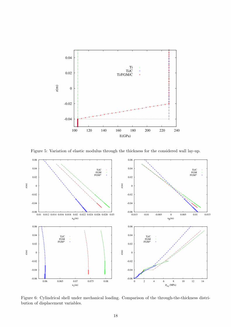
Data of typical materials that could be used in pressure vessel construction are given in Table 1 whereE is the young modulus, ρ is the density, σf is the allowable stress and ν is the Poisson ratio. Acomparison of the performance of these materials is given for the cylindrical shell case in Table 2.Cylinders constituted by a metallic and carbon fiber wall of the same volume are considered (samethickness). The geometrical data of the shell is as follows: the internal radius Ri is fixed to 0.4 [m], thelength along the β direction L is 1 [m], the radii are Rα = 1[m], Rβ = ∞[m] and the external radiusRe is a function of thickness h, which varies according to the analysis.
Table 2 compares the weight [W] of the three metallic walls with that of the carbon fiber ones. Themaximum pressure pMaxis also given. The advantage using carbon fiber is very evident. Figure 4 showsthe maximum pressures vs the wall thickness. The Von Mises yielding criteria σEq has been used forcomparison purposes. The advantage of using carbon fiber has been confirmed.
4.2.1 Cylindrical shell with FGM layers
Three layered walls are considered with the following geometrical data:
Ti/C Titanium liner (h=0.01[m]) and carbon fiber wall (h=0.09[m]) with htot = 0.1[m]
FGM Titanium liner (h=0.01[m]) FGM layer (h=0.02[m]) carbon fiber wall (h=0.07[m]) with htot =0.1[m]
FGM* Titanium liner (h=0.01[m]) FGM layer (h=0.02[m]) carbon fiber wall (h=0.09[m]) with htot =0.12[m]
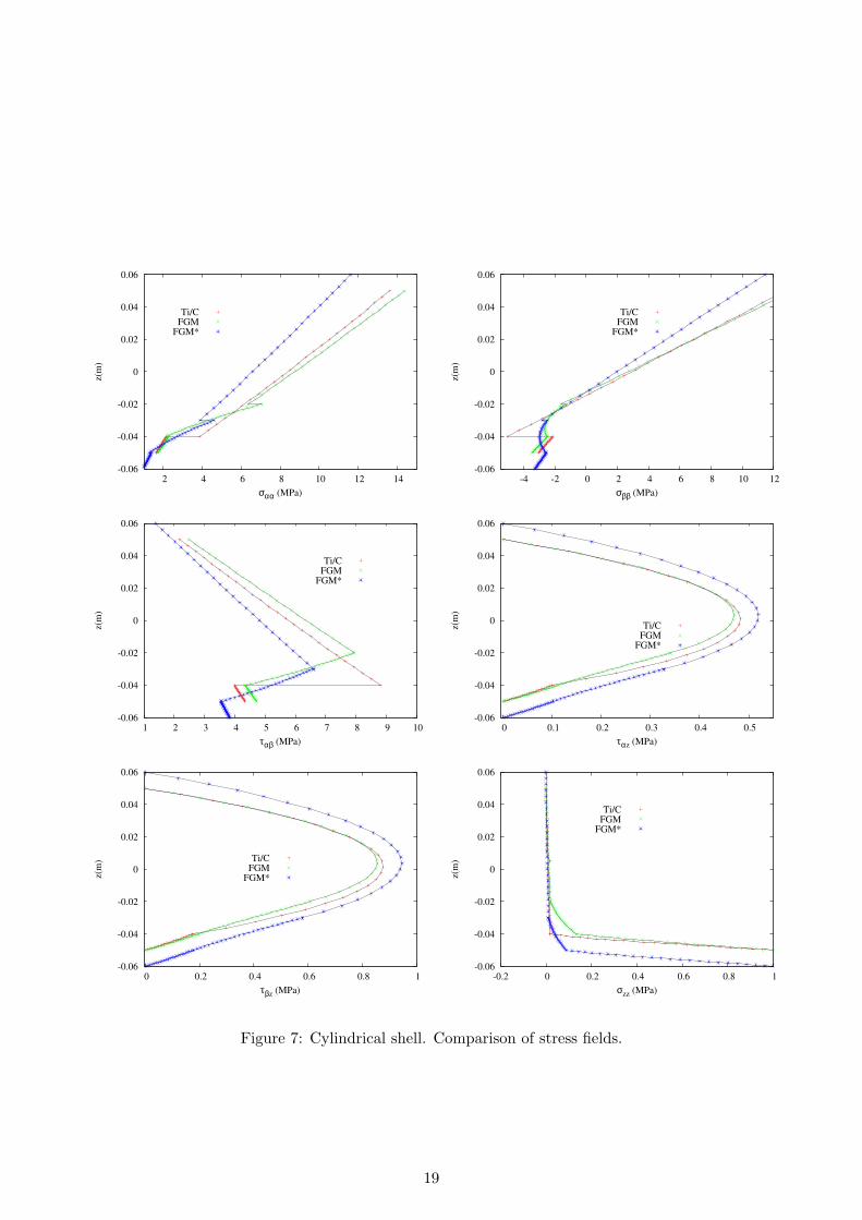
The wall data are summarized in Table 3. The distribution of the Young modulus in the wall directionis given in Figure 5. The third case, denoted as FGM∗, is heavier than the other two ones. It showsthe possible advantages of adding additional FGM layers to the two existing walls. Table 4 shows theweight, the maximum stresses and the interlaminar shear stresses for the three analyzed configuration:τi.l.(1) is the interlaminar stress between the Titanium liner and the FG layer while τi.l(2) is the samestress between the FG layer and the main Carbon fiber structure. The advantage of using the FGMlayers, with respect to maximum shear stresses, has been confirmed. The advantages of the FGM∗wall, with respect to the maximum equivalent stress, is also evident. Figures 6 and 7 compare thevariations in displacement and stresses along the thickness for the three configurations. It should bepointed out, that the FGM∗ case refers to a thicker wall. As a consequence the cylinder shows higherstiffness in the FGM* case and related displacements are lower than TI/C and FGM cases. The latteris the most deformable one. σeq plot shows that the FGM* wall correspond to the lowest gradient atthe Titanium-Carbon interface.The capability of FGM layers to reduce discontinuous stress fields is clearly evident; the transverseshear stress barely increases in the FGM case, due to higher shear deformations of the FGM layer withrespect to Titanium.Tables 4 and 5 provide a detailed comparison, in terms of shear and normal stress as well as in termsof maximum allowable pressure p related to a von-Mises criterion (which is dominated by normal stressvalues), and to a shear stress criterion which is dominated by τi.l.. The lower values of τi.l. could reduce
6
the possibility of delamination growth. The analysis shows that the presence of FGM layers leads toan increase in the allowable pressure ∆p = 54.00 MPa, which corresponds to 2.93%, where ∆p is thedifference between the classical laminate and the FGM wall values. Such a relatively small percentagecould become very significant in space mission design.The following relevant conclusions can be drawn considering the in-plane stress results:
• The use of FGM layers leads to a strong reduction in the circumferential normal stress σαα values.
• The strong reduction in the compressive values of the longitudinal stress σββ and the shear stressσαβ introduced by the FGM layers is of particular interest. That is the FGM layers are expectedto increase the buckling resistance of the wall.In other words, the local buckling phenomena,which are one of the most relevant design requirements for two-layered made pressure vessels, arereduced by the FGM layers.
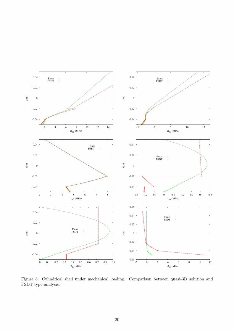
Figure 8 shows that FSDT analyses, such as those available in commercial FE codes, are ineffective intracing the stress behavior in the thickness directions. The use of FSDT shell elements could lead tocompletely erroneous conclusions. Better results could be reproduced by using solid elements, whichcould lead to a significant increase of the computational costs.
4.3 Spherical cap loaded by internal pressure
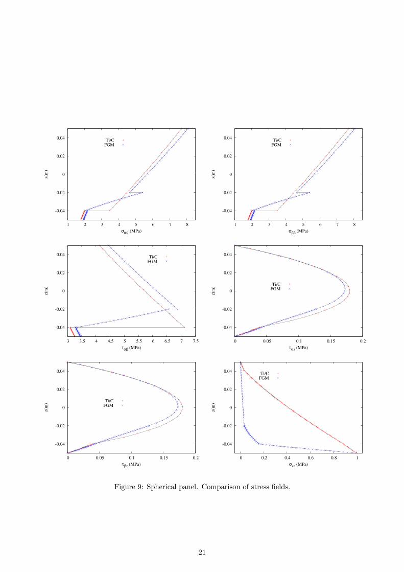
Similar results have been derived for the spherical panels, as confirmed in Figure 9. The data arethe same as those of the previous section. The FGM layer leads to continuity for transverse stresscomponents; discontinuity is reduced for in-plane stresses with respect to the original spherical two-layered wall panel. In plane shear stresses are reduced when a FGM layer is used. As in the cylindricalcase the FGM layers are expected to increase the buckling resistance of the wall in both case oflongitudinal and shear stresses. To be noticed that present analysis has been limited to sphericalpanels that are considered as part of a spherical pressure vessel. In that case the stress fields do notchange over the shell reference surface. In practical cases the spherical parts are connected to thecylindrical shell and the above assumption could result not applicable.
4.4 Cylindrical shell subjected to thermal loading
A thermal stress analysis has also been conducted. The temperature distribution in the shell thicknessis not assumed linear, but is computed by solving the Fourier heat conduction equation. For the kth
homogeneous orthotropic layer, the differential Fourier’s equation of heat conduction reads:(Kk
1
H2α
) ∂2T
∂α2+
(Kk2
H2β
) ∂2T
∂β2+ Kk
3
∂2T
∂z2= 0 , (10)
Kk1 , Kk
2 and Kk3 are the thermal conductivities along the three shell directions α, β and z; they are
constant in each layer in case of classical materials, but they depend by the thickness coordinate incase of FGMs. ∂ indicates the partial derivative. Hα = (1 + zk/Rk
α) and Hβ = (1 + zk/Rkβ) are
the metric coefficients. In case of plates the Eq.(10) has Hα = Hβ = 1 and the coefficients Kk1 , Kk
2
and Kk3 depend on z because some layers k can be in FGM. In case of shell we can define three new
coefficients K∗k1 = Kk
1 (z)H2
α, K∗k
2 = Kk2 (z)
H2β
and K∗k3 = Kk
3 (z), which in a generic layer k depend on the
thickness coordinate of the shell. K∗k1 and K∗k
2 can depend by the thickness coordinate z for tworeasons: possible use of FGM layers and/or presence of curvature in case of shells; K∗k
3 can depend byz coordinate only in case of FGM layers. So:
K∗k1
∂2T
∂α2+ K∗k
2
∂2T
∂β2+ K∗k
3
∂2T
∂z2= 0 . (11)
7
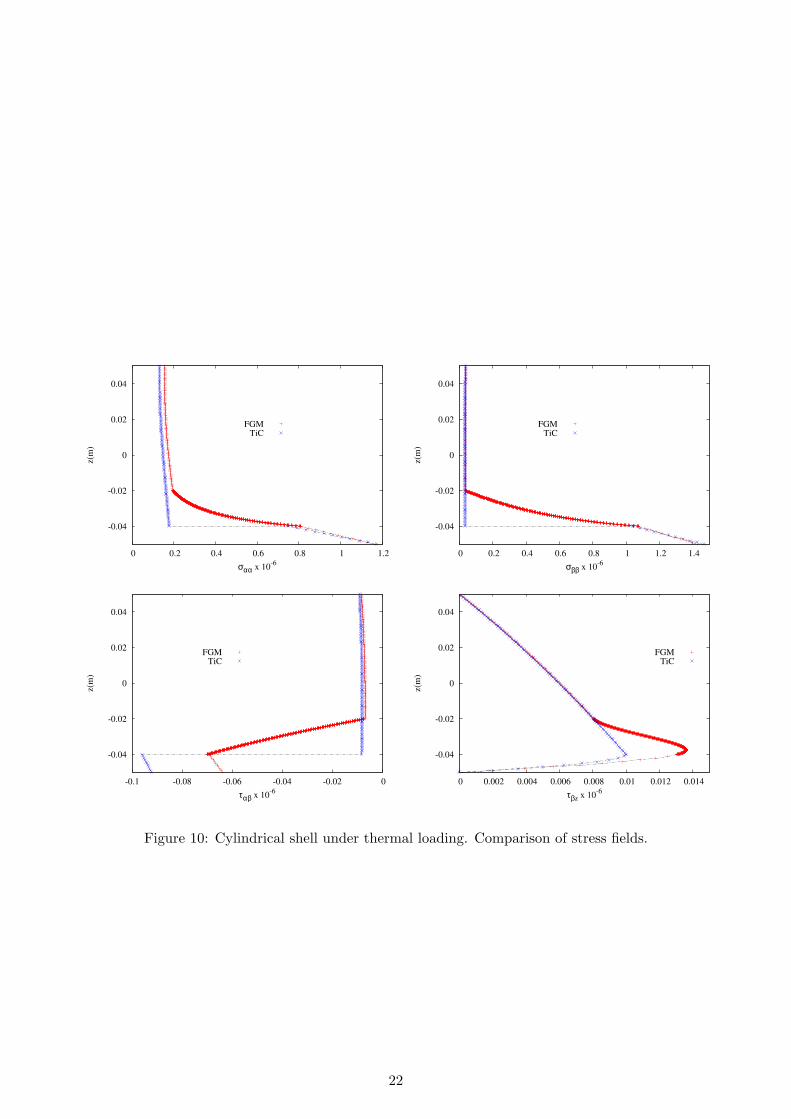
That equation has been solved according to the closed form solution technique which has been exten-sively described the authors articles [30], [31], and [32]. For sake of concisennes the governing equationsfor the thermomechanical cases are omitted, these can be found in [32].Interface discontinuities are eliminated by the FGM layer, as in the mechanical loading case. In-planeshear maximum values are reduced by reducing buckling failure, (Figure 10). This reduction appearsmore significant that those found in the case of mechanical loadings. That is, by grading thermalproperties major advantages are obtained.
5 Conclusions
This work has shown the advantage of using an FGM layer in a two-layered pressure vessel wall witha layer-liner in Titanium and a structural restraint-layer made of Carbon fibers. FGM layers reduceinterlaminar discontinuity and reduce the in-plane stresses values, which are relevant to buckling phe-nomena. The First order shear deformation shell models that are usually considered in commercialfinite element codes could lead to erroneous conclusions and the use of more computational expensivemodels that employ solid elements should be introduced. In this contest, the use of refined shell modelsappears mandatory. Future work should not be limited to simple shell elements (rings and sphericalcaps) by including complete pressure vessels geometry with FGM layers; effects of both geometricaland physical nonlinearities should be investigated too.
References
[1] S. Chattopadhyay. Pressure Vessels: Design and Practice, CRC Press, New York, 2004.
[2] D. Bushnell. Computerized buckling analysis for shells, Lockheed Palo Alto Research Laboratory,Palo Alto, 1985.
[3] S.H. Zhang, L. Jiang, B.L. Wang and Z. R. Wang. Finite-element analysis of the integral hydro-bulge forming of double-layer gap spherical vessels. International Journal of Pressure Vessels andPiping, 68, 161-167, 1996.
[4] S.H. Zhang, B.L. Wang, Y.L. Shang, X.R. Kong, J.D. Hu, and Z.R. Wang. Three-dimensionalfinite element simulation of the integral hydrobulge forming of a spherical LPG tank. InternationalJournal of Pressure Vessels and Piping, 65, 47-52, 1996.
[5] M. R. Baum. Rupture of a gas-pressurized cylindrical vessel: the velocity of a detached end-cap.Journal Loss Pm. Process Ind., 8, 149-161, 1995.
[6] R. Khan and W. Uddin. The stability of conical end caps with spherical tips as end closures formpressure vessels. International Journal of Pressure Vessels and Piping, 64, 11-16, 1995.
[7] A. Tafreshi. Numerical analysis of thin torispherical end closures. International Journal of PressureVessels and Piping, 71, 77-88, 1997.
[8] J. Mackerle. Finite elements in the analysis of pressure vessels and piping, an addendum: Abibliography (1996-1998). International Journal of Pressure Vessels and Piping, 76, 461-485, 1999.
[9] J. Mackerle. Finite elements in the analysis of pressure vessels and piping, an addendum: Abibliography (1996-1998). International Journal of Pressure Vessels and Piping, 79, 1-26, 2002.
[10] J. Mackerle. Finite elements in the analysis of pressure vessels and piping, an addendum: Abibliography (20012004). International Journal of Pressure Vessels and Piping, 82, 571-592, 2005.
8
[11] Z. Li and S.L. Gobbi. Laser welding for lightweight structures. Journal of Materials ProcessingTechnology, 70, 137-144, 1997.
[12] J.G. Teng and X. Lin. Fabrication of small models of large cylinders with extensive welding forbuckling experiments. Thin-Walled Structures, 43, 1091-1114, 2005.
[13] D.T. Jones, I.A. Jones and V. Middleton. Improving composite lay-up for non-spherical filament-wound pressure vessels. Composites: Part A, 27A, 311-317, 1996.
[14] D. Cohen. Influence of filament winding parameters on composite vessel quality and strength.Composites: Part A, 28A, 1034-1047, 1997.
[15] D. Cohen, S.C. Mantell and L. Zhao. The effect of fiber volume fraction on filament wound com-pisite pressure vessel strenght. Composites: Part B, 32, 413-429, 2001.
[16] M. Koizumi, “The concept of FGM”, Ceram. Trans. Funct. Graded Mater., 34, 3-10, 1993.
[17] S. Suresh and A. Mortensen, “Fundamentals of functionally graded materials”, Barnes and NoblePublications, 1998.
[18] S.Brischetto, R.Leetsch, E.Carrera, T.Wallmersperger and B. Kroplin. Thermo-Mechanical Bend-ing Of Functionally Graded Plates. Journal of Thermal Stresses, 31, 286-308, 2008.
[19] V. Birman, L.W. Bird, Modeling and Analysis of Functionally Graded Materials and Structures.Applied Mechanics Reviews, 60, 195-217, 2007
[20] E. Carrera. Multilayered Shell Theories Accounting for layerwise mixed description - Part I,II.AIAA Journal, 37(9), 1107-1124, 1999.
[21] E. Carrera. Develompments, ideas and evaluations based upon Reissner’s mixed variational theo-rem in the modeling of multilayered plates and shells. Applied Mechanics Reviews, 54(4), 301-329,2001.
[22] Carrera, E. Theories and finite elements for multilayered plates and shells: a unified compactformulation with numerical assessments and benchmarks. Archivies of Computational Methods inEngineering, 10, 215-296, 2003.
[23] J.N. Reddy. Mechanics of Laminated Composite Plates, Theory and Analysis. CRC Press, NewYork, 2004.
[24] E. Carrera, S. Brischetto, A. Robaldo. Variable Kinematic Model for the Analysis of FunctionallyGraded Material Plates. AIAA Journal, 46, 194-203, 2008.
[25] S. Brischetto and E. Carrera. Importance of Higher Order Modes and Refined Theories in FreeVibration Analysis of Composite Plates. Journal of Applied Mechanics, 77, 2010.
[26] K. Washizu. Variational methods in elasticity and plasticity, Pergamon Press, New York, 1968.
[27] E. Reissner. On a certain mixed variational theory and a proposed application. InternationalJournal for Numerical Methods in Engineering, 20, 1366-1368, 1984.
[28] E. Carrera. A class of two dimensional theories for multilayered plates analysis. Atti Accademiadelle Scienze di Torino. Memorie Scienze Fisiche. 19-20, 49-87, 1995.
[29] E. Carrera. Multilayered Shell Theories Accounting for layerwise mixed description - Part I,II.AIAA Journal. 37(9), 1107-1124, 1999.
9
[30] E. Carrera, An assessment of Mixed and Classical Theories for thermal stress analysis of orthotropicMultilayered Plates. Journal of Thermal Stress, 23, 797-831, 2000.
[31] E. Carrera. Temperature Profile Influence on Layered Plates Response Considering Classical andAdvanced Theories,. AIAA Journal, 40, 1885-1896, 2002.
[32] M. Cinefra, S. Brischetto, E. Carrera, Beloueattar S., Thermo-mechanical analysis of functionallygraded shells, Journal of Thermal Stress, in press
[33] E. Carrera, Multilayered Shell Theories Accounting for layerwise mixed description - Part I,II -Governing Equations and Numerical evluations, AIAA Journal, 37, 1107-1124, 1999.
[34] E. Carrera, A study of transverse normal stress effect on vibration of multylayered plates andshells, Journal of Sound and Vibrations, 225(5), 803-829, 1999.
10
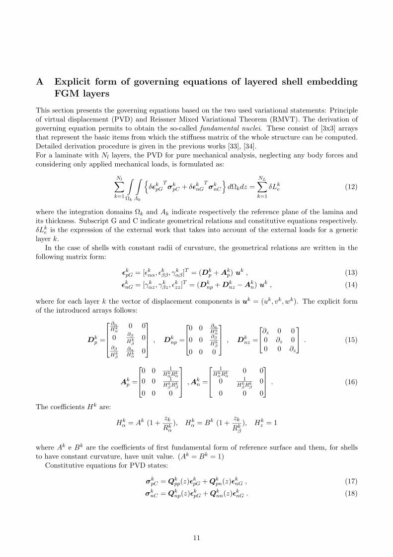
A Explicit form of governing equations of layered shell embeddingFGM layers
This section presents the governing equations based on the two used variational statements: Principleof virtual displacement (PVD) and Reissner Mixed Variational Theorem (RMVT). The derivation ofgoverning equation permits to obtain the so-called fundamental nuclei. These consist of [3x3] arraysthat represent the basic items from which the stiffness matrix of the whole structure can be computed.Detailed derivation procedure is given in the previous works [33], [34].For a laminate with Nl layers, the PVD for pure mechanical analysis, neglecting any body forces andconsidering only applied mechanical loads, is formulated as:
Nl∑
k=1
∫
Ωk
∫
Ak
δεk
pGTσk
pC + δεknG
Tσk
nC
dΩkdz =
NL∑
k=1
δLke (12)
where the integration domains Ωk and Ak indicate respectively the reference plane of the lamina andits thickness. Subscript G and C indicate geometrical relations and constitutive equations respectively.δLk
e is the expression of the external work that takes into account of the external loads for a genericlayer k.
In the case of shells with constant radii of curvature, the geometrical relations are written in thefollowing matrix form:
εkpG = [εk
αα, εkββ, γk
αβ]T = (Dkp + Ak
p) uk , (13)
εknG = [γk
αz, γkβz, ε
kzz]
T = (Dknp + Dk
nz −Akn) uk , (14)
where for each layer k the vector of displacement components is uk = (uk, vk, wk). The explicit formof the introduced arrays follows:
Dkp =
∂α
Hkα
0 0
0 ∂β
Hkβ
0∂β
Hkβ
∂α
Hkα
0
, Dk
np =
0 0 ∂α
Hkα
0 0 ∂β
Hkβ
0 0 0
, Dk
nz =
∂z 0 00 ∂z 00 0 ∂z
. (15)
Akp =
0 0 1
HkαRk
α
0 0 1Hk
βRkβ
0 0 0
, Ak
n =
1Hk
αRkα
0 00 1
HkβRk
β
0
0 0 0
. (16)
The coefficients Hk are:
Hkα = Ak (1 +
zk
Rkα
), Hkα = Bk (1 +
zk
Rkβ
), Hkz = 1
where Ak e Bk are the coefficients of first fundamental form of reference surface and them, for shellsto have constant curvature, have unit value. (Ak = Bk = 1)
Constitutive equations for PVD states:
σkpC = Qk
pp(z)εkpG + Qk
pn(z)εknG , (17)
σknC = Qk
np(z)εkpG + Qk
nn(z)εknG . (18)
11
where Qkpp, Q
kpn, Qk
np, Qknn are [3x3] sub-arrays containing the elastic coefficients for an orthotropic
layer in the structure reference system.Similarly, the RMVT (Eq.(7)) for a laminate becomes:
Nl∑
k=1
∫
Ωk
∫
Ak
δεT
pGσpC + δεTnGσnM + δσT
nM (εnG − εnC)
dΩkdz =NL∑
k=1
δLke (19)
where constitutive equations states:
σkpC = Q
kpp(z) εk
pG + Qkpn(z) σk
nM , (20)
εknC = Q
knp(z) εk
pG + Qknn(z) σk
nM , (21)
where the new coefficients are:
Qkpp(z) = Qk
pp(z)−Qkpn(z)Qk
nn(z)−1Qknp(z) , Q
kpn(z) = Qk
pn(z)Qknn(z)−1 , (22)
Qknp(z) = −Qk
nn(z)−1Qnp(z) , Qknn(z) = Qk
nn(z)−1 .
In case of FGM layers, the coefficients in Eqs. (17), (22), and (20) vary in the thickness direction zaccording to a given law:
Q(z) = Q0 ∗ g(z), (23)
where Q0 is the reference stiffness matrix and g(z) gives the variation along z. For convenience, thethickness functions given in Eq.(3), are used to approximate Q(z):
Q(z) = Fb(z)Qb + Ft(z)Qt + Fγ(z)Qγ = Fr Qr with r = 1, ..., 10 (24)
where Qr are constant in z and thickness functions Fr are a combination of Legendre polynomials.Previous formula consists of the unique novelty for the introduction of FGM in the variable kinematicmodel in the CUF. By considering the approximation given in Eq.(24), it is possible to obtain a generalform of constitutive relations for the PVD and RMVT case, they are valid for both cases of functionallygraded materials and materials with constant properties through the thickness direction z. For the PVDmodels, the constitutive equations are:
σkpC = FrQ
kpprε
kpG + FrQ
kpnrε
knG , (25)
σknC = FrQ
knprε
kpG + FrQ
knnrε
knG . (26)
In the case of RMVT models, the constitutive equations state:
σkpC = FrQ
kppr εk
pG + FrQkpnr σk
nM , (27)
εknC = FrQ
knpr εk
pG + FrQknnr σk
nM , (28)
where k = 1, . . . , Nl indicates the considered layers, and r = 1, . . . , 10 is the loop to approximate theFGM properties varying with the z coordinate. In the case of materials with constant properties in z,the loop on r index is not necessary and the material coefficients are constant.
In order to obtain a strong form of differential equations on the domain Ωk, as well as the correspon-dence boundary conditions on edge Γk, the integration by parts is required. The governing equationson the domain Ωk, in the PVD case, are:
δuksT
: Kkτsruu uk
τ = P kus (29)
12
Boundary conditions of are:Πkτsr
uu ukτ = Πkτsr
uu ukτ (30)
In Eq.(29), P kuτ is the external mechanical load and the fundamental nucleus Kkτsr
uu has to be assembledthrough the depicted indexes: the internal loop is on index r; τ and s consider the order of expansion in zfor the displacements; superscript k indicates the assembling on the number of layers. The fundamentalnucleus Kkτsr
uu for the stiffness matrix and the fundamental nucleus Πkτsruu for the boundary conditions
are:
Kkτsruu =
∫
Ak
[(−Dk
p + Akp
)T (FrQ
kppr(D
kp + Ak
p) + FrQkpnr(D
knp + Dk
nz −Akn)
)+ (31)
(−Dk
np + Dknz −Ak
n
)T (FrQ
knpr(D
kp + Ak
p) + FrQknnr(D
knp + Dk
nz −Akn)
)]
FsFτHkαHk
βdz ,
Πkτsruu =
∫
Ak
[IkT
p
(FrQ
kppr(D
kp + Ak
p) + FrQkpnr(D
knp + Dk
nz −Akn)
)+ (32)
IkTnp
(FrQ
knpr(D
kp + Ak
p) + FrQknnr(D
knp + Dk
nz −Akn)
)]FsFτH
kαHk
βdz .
Ikp and Ik
np are identity matrices to perform the integration by parts.
I =
1 0 00 1 00 0 1
, Ik
p =
1Hk
α0 0
0 1Hk
β
01
Hkβ
1Hk
α0
, Ik
np =
0 0 1
Hkα
0 0 1Hk
β
0 0 0
. (33)
The governing equations in the RMVT case are:
δuks : Kkτsr
uu ukτ + Kkτsr
uσ σknτ = P k
usδσkns : Kkτsr
σu ukτ + Kkτsr
σσ σknτ = 0
four fundamental nuclei relative to stiffness array are obtained. These are completely different fromthose obtained in the PVD case while the inertial array does not change.Corresponding boundary conditions of Neumann type are:
Πkτsruu uk
τ + Πkτsruσ σk
nτ = Πkτsruu uk
τ + Πkτsruσ σk
nτ
The fundamental nuclei can be obtained:
Kkτsruu =
∫
Ak
[(−Dk
p + Akp)
T (FrQkppr(D
kp + Ak
p))]FsFτH
kαHk
βdz , (34)
Kkτsruσ =
∫
Ak
[(−Dk
p + Akp)
T (FrQkpnr) + (−Dk
np + Dknz −Ak
n)T]FsFτH
kαHk
βdz , (35)
Kkτsrσu =
∫
Ak
[(Dk
np + Dknz −Ak
n)− (FrQknpr)(D
kp + Ak
p)]FsFτH
kαHk
βdz , (36)
Kkτsrσσ =
∫
Ak
[− FrQ
knnr
]FsFτH
kαHk
βdz , (37)
13
The nuclei for boundary conditions on edge Γk are:
Πkτsruu =
∫
Ak
[Ik
pTFrQ
kppr(D
kp + Ak
p)]FsFτH
kαHk
βdz , (38)
Πkτsruσ =
∫
Ak
[Ik
pTFrQ
kpnr + Ik
npT]FsFτH
kαHk
βdz . (39)
14
Material E[Gpa] ρ[Kg/m3] σf [Mpa] ν
T itanium 105 4507 240 0.3Aluminium 70 2700 124 0.3Steel 220 7850 580 0.3CarbonFiber 230 1800 3600 0.3FGM V ar. V ar. − 0.3
Table 1: Material properties.
Ti Al St CW [Kg] 1274.32 764.1 2221.55 509.4σEqMAX [MPa] 25.72 25.72 25.72 25.72σf [MPa] 240 124 580 3600pMax [MPa] 18.66 9.64 45.10 279.92
Table 2: Comparison of pressure vessels made by single layer wall of constant thickness.
Ti/C Ti/FGM/C Ti/FGM*/ChT ot [m] 0.1 0.1 1.2hFGM [m] − 0.02 0.02hC [m] 0.09 0.07 0.9
Table 3: Thickness data of the considered pressure vessels walls.
15
Ti/C Ti/FGM/C Ti/FGM*/CWeight [Kg] 577.82 577.82 693.12σEqMAX [MPa] 13.627 14.377 11.610τMAX [MPa] 0.4831 0.4703 0.5193τi.l.(1) [MPa] − 0.3409 0.3276τi.l.(2) [MPa] 0.1001 0.1117 0.1019
Table 4: Comparison of weight and allowable stresses.
Max value Ti/C Ti/FGM/C advantageταβ [MPa] 8.8081 7.9503 ∗σββ [MPa] 12.809 13.280ταz [MPa] 0.4831 0.4703 ∗τβz [MPa] 0.8762 0.8548 ∗
Maximum pressure obtained by various criteriap(τ) [MPa] 1791.0 1845.0 ∗p(σEq) [MPa] 264.18 250.40
Table 5: Cylindrical shell under static pressure. Comparison between pure two-layered wall and two-layered wall with FGM layers.
Figure 1: Geometry of pressure vessel. Cylindrical and spherical shells analyzed in the present work.
16
αβ
Figure 2: Geometry of cylindrical shell.
h
Carbon fiber
Titanium liner
0.9 h
0.1 h
z
β
h
Carbon fiber
Titanium liner
FGM
0.7 h
0.2 h
0.1 h
z
β
Figure 3: Layers and wall lay-up geometry of the considered shells.
0.1
1
10
100
pM
ax
(Mp
a)
h(m)
AlTiStC
0.001 0.01 0.05 0.1
Figure 4: Allowable pressure vs wall thickness. Comparison of various wall lay-up for a cylindricalshell.
17
-0.04
-0.02
0
0.02
0.04
100 120 140 160 180 200 220 240
z(m
)
E(GPa)
TiTi/C
Ti/FGM/C
Figure 5: Variation of elastic modulus through the thickness for the considered wall lay-up.
-0.06
-0.04
-0.02
0
0.02
0.04
0.06
0.01 0.012 0.014 0.016 0.018 0.02 0.022 0.024 0.026 0.028 0.03
z(m
)
uα(m)
Ti/CFGM
FGM*
-0.06
-0.04
-0.02
0
0.02
0.04
0.06
-0.015 -0.01 -0.005 0 0.005 0.01 0.015
z(m
)
uβ(m)
Ti/CFGM
FGM*
-0.06
-0.04
-0.02
0
0.02
0.04
0.06
0.06 0.065 0.07 0.075 0.08
z(m
)
uz(m)
Ti/CFGM
FGM*
-0.06
-0.04
-0.02
0
0.02
0.04
0.06
0 2 4 6 8 10 12 14
z(m
)
σeq (MPa)
Ti/CFGM
FGM*
Figure 6: Cylindrical shell under mechanical loading. Comparison of the through-the-thickness distri-bution of displacement variables.
18
-0.06
-0.04
-0.02
0
0.02
0.04
0.06
2 4 6 8 10 12 14
z(m
)
σαα (MPa)
Ti/CFGM
FGM*
-0.06
-0.04
-0.02
0
0.02
0.04
0.06
-4 -2 0 2 4 6 8 10 12
z(m
)
σββ (MPa)
Ti/CFGM
FGM*
-0.06
-0.04
-0.02
0
0.02
0.04
0.06
1 2 3 4 5 6 7 8 9 10
z(m
)
ταβ (MPa)
Ti/CFGM
FGM*
-0.06
-0.04
-0.02
0
0.02
0.04
0.06
0 0.1 0.2 0.3 0.4 0.5
z(m
)
ταz (MPa)
Ti/CFGM
FGM*
-0.06
-0.04
-0.02
0
0.02
0.04
0.06
0 0.2 0.4 0.6 0.8 1
z(m
)
τβz (MPa)
Ti/CFGM
FGM*
-0.06
-0.04
-0.02
0
0.02
0.04
0.06
-0.2 0 0.2 0.4 0.6 0.8 1
z(m
)
σzz (MPa)
Ti/CFGM
FGM*
Figure 7: Cylindrical shell. Comparison of stress fields.
19
-0.04
-0.02
0
0.02
0.04
2 4 6 8 10 12 14
z(m
)
σαα (MPa)
ExactFSDT
-0.04
-0.02
0
0.02
0.04
-5 0 5 10 15
z(m
)
σββ (MPa)
ExactFSDT
-0.04
-0.02
0
0.02
0.04
2 3 4 5 6 7 8
z(m
)
ταβ (MPa)
ExactFSDT
-0.04
-0.02
0
0.02
0.04
-0.3 -0.2 -0.1 0 0.1 0.2 0.3 0.4 0.5
z(m
)
ταz (MPa)
ExactFSDT
-0.04
-0.02
0
0.02
0.04
0 0.1 0.2 0.3 0.4 0.5 0.6 0.7 0.8 0.9
z(m
)
τβz (MPa)
ExactFSDT
-0.06
-0.04
-0.02
0
0.02
0.04
0.06
-2 0 2 4 6 8 10 12
z(m
)
σzz (MPa)
ExactFSDT
Figure 8: Cylindrical shell under mechanical loading. Comparison between quasi-3D solution andFSDT type analysis.
20
-0.04
-0.02
0
0.02
0.04
1 2 3 4 5 6 7 8
z(m
)
σαα (MPa)
Ti/CFGM
-0.04
-0.02
0
0.02
0.04
1 2 3 4 5 6 7 8
z(m
)
σββ (MPa)
Ti/CFGM
-0.04
-0.02
0
0.02
0.04
3 3.5 4 4.5 5 5.5 6 6.5 7 7.5
z(m
)
ταβ (MPa)
Ti/CFGM
-0.04
-0.02
0
0.02
0.04
0 0.05 0.1 0.15 0.2
z(m
)
ταz (MPa)
Ti/CFGM
-0.04
-0.02
0
0.02
0.04
0 0.05 0.1 0.15 0.2
z(m
)
τβz (MPa)
Ti/CFGM
-0.04
-0.02
0
0.02
0.04
0 0.2 0.4 0.6 0.8 1
z(m
)
σzz (MPa)
Ti/CFGM
Figure 9: Spherical panel. Comparison of stress fields.
21
-0.04
-0.02
0
0.02
0.04
0 0.2 0.4 0.6 0.8 1 1.2
z(m
)
σαα x 10-6
FGMTiC
-0.04
-0.02
0
0.02
0.04
0 0.2 0.4 0.6 0.8 1 1.2 1.4
z(m
)
σββ x 10-6
FGMTiC
-0.04
-0.02
0
0.02
0.04
-0.1 -0.08 -0.06 -0.04 -0.02 0
z(m
)
ταβ x 10-6
FGMTiC
-0.04
-0.02
0
0.02
0.04
0 0.002 0.004 0.006 0.008 0.01 0.012 0.014
z(m
)
τβz x 10-6
FGMTiC
Figure 10: Cylindrical shell under thermal loading. Comparison of stress fields.
22


![Functionally Graded Precast Slabs · Development of Weight-Optimised, Functionally Graded Precast Slabs ... “Leicht Bauen mit Beton” [“Lightweight Construction with Concrete”]](https://img.pdfslide.us/doc/110x75/5ca4dedc88c993b8788b467c/functionally-graded-precast-slabs-development-of-weight-optimised-functionally.jpg)


![Analysis of Viscoelastic Functionally Graded Sandwich ...journals.iau.ir/article_668608_b33f4af4905ff4be3afd5b0759e29604.p… · can be laminated composites [4], functionally graded](https://img.pdfslide.us/doc/110x75/60222b2a2fef0d1447096621/analysis-of-viscoelastic-functionally-graded-sandwich-can-be-laminated-composites.jpg)