Embed Size (px)
Citation preview
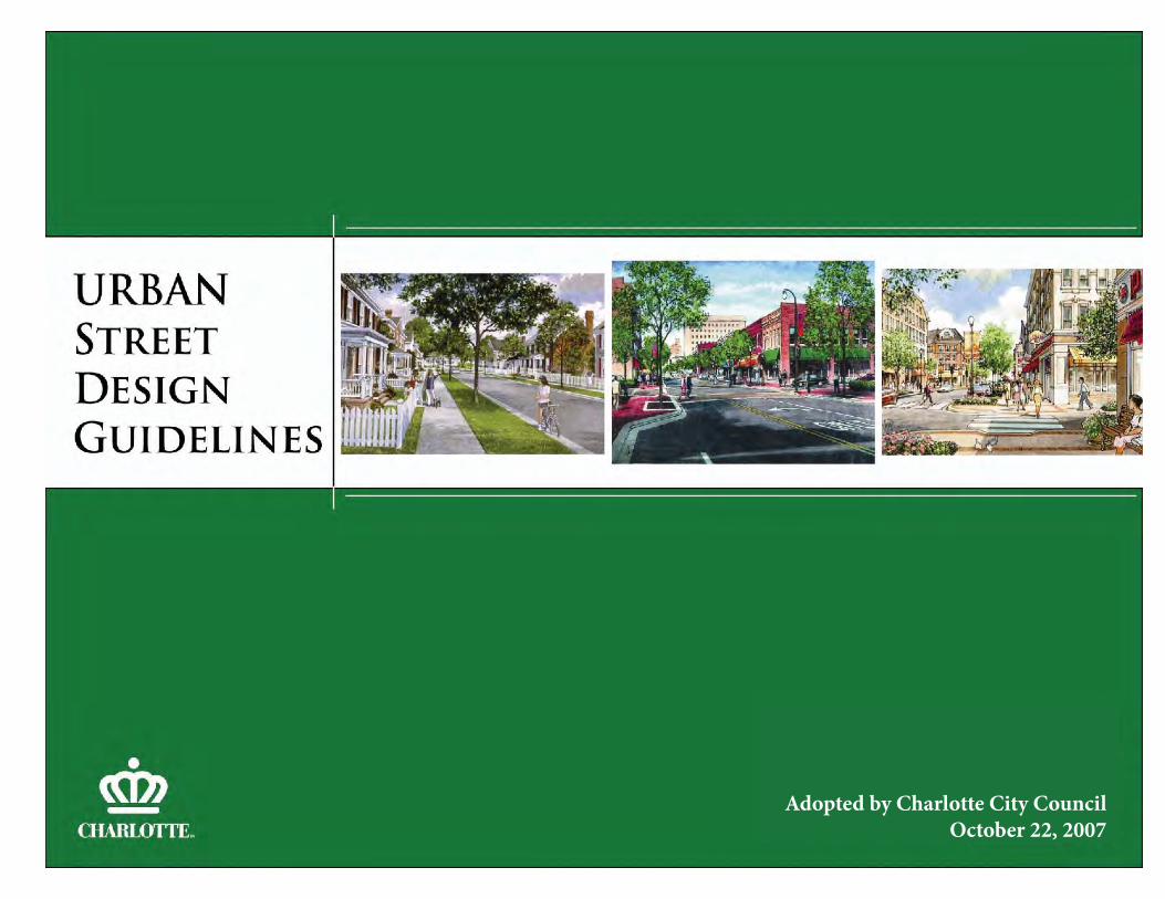
Adopted by Charlotte City Council October 22, 2007
Th is document was prepared by City of Charlotte staff from the following departments:
Charlotte Department of TransportationCharlotte-Mecklenburg Planning Department
Charlotte Area Transit SystemEngineering and Property Management
Additional technical input was provided by HNTB, Reid Ewing, and Kenneth Voigt.
CONTACT INFORMATION:
For more information about this document,please visit www.charmeck.org/departments/transportation or contact:
Tracy NewsomeCharlotte Department of Transportation
600 East Fourth StreetCharlotte, NC 28202
U R BA N S T R E E T D E S I G N G U I D E L I N E SA d o p t e d O c t o b e r 2 2 , 2 0 0 7

iUr b a n S t r e e t D e s i g n G u i d e l i n e s
Policy Summary . . . . . . . . . . . . . . . . . . . . . . . . . . . . . . . . . . . . . . . . . . . . . . . . . . . . iii
Chapter 1 - Redefi ning Charlotte’s Streets . . . . . . . . . . . . . . . . . . . . . . . . . 1Why Do We Need New Urban Street Design Guidelines? . . . . . . . . . . . . . . . 1What Are the Guidelines Trying to Achieve? . . . . . . . . . . . . . . . . . . . . . . . . . . 6Th e New Street Types: Creating an Urban Street Network . . . . . . . . . . . . . . 7How Do Th ese Guidelines Relate to Other Transportation Planning Activities? . . . . . . . . . . . . . . . . . . . . . . . . . . . 10Content of the Guidelines . . . . . . . . . . . . . . . . . . . . . . . . . . . . . . . . . . . . . . . . . 11Related Content Items to be Developed . . . . . . . . . . . . . . . . . . . . . . . . . . . . . . 11
Chapter 2 - Designing Streets for Multiple Users . . . . . . . . . . . . . . . . . 13 Assessing Tradeoff s: Who is Using the Street? . . . . . . . . . . . . . . . . . . . . . . . . . 13 What Do Motorists Want From Streets?. . . . . . . . . . . . . . . . . . . . . . . . . . . . . . 14 What Do Pedestrians Want From Streets? . . . . . . . . . . . . . . . . . . . . . . . . . . . . 16 What Does Transit Want From Streets? . . . . . . . . . . . . . . . . . . . . . . . . . . . . . 20 What Do Bicyclists Want From Streets? . . . . . . . . . . . . . . . . . . . . . . . . . . . . . 23 What Do the Adjacent Land Uses Want From Streets? . . . . . . . . . . . . . . . . . 26 Complementary and Competing Stakeholder Perspectives. . . . . . . . . . . . . . 29 Design Element Matrix: Diff erent User Perspectives . . . . . . . . . . . . . . . . . . 30
TA B L E O F C O N T E N T S
Ur b a n S t r e e t D e s i g n G u i d e l i n e sii
Chapter 3 - Applying the Guidelines . . . . . . . . . . . . . . . . . . . . . . . . . . . . . . . 51 Applying the Guidelines: Six Steps . . . . . . . . . . . . . . . . . . . . . . . . . . . . . . . . . . 53 Final Comments on the Six Steps . . . . . . . . . . . . . . . . . . . . . . . . . . . . . . . . . . . 60
Chapter 4 - Segments . . . . . . . . . . . . . . . . . . . . . . . . . . . . . . . . . . . . . . . . . . . . 61 Main Streets . . . . . . . . . . . . . . . . . . . . . . . . . . . . . . . . . . . . . . . . . . . . . . . . . . . 66
Avenues . . . . . . . . . . . . . . . . . . . . . . . . . . . . . . . . . . . . . . . . . . . . . . . . . . . . . . . 74 Boulevards . . . . . . . . . . . . . . . . . . . . . . . . . . . . . . . . . . . . . . . . . . . . . . . . . . . . 84 Parkways . . . . . . . . . . . . . . . . . . . . . . . . . . . . . . . . . . . . . . . . . . . . . . . . . . . . . . 92 Local Residential Streets . . . . . . . . . . . . . . . . . . . . . . . . . . . . . . . . . . . . . . . . . 100 Local Offi ce/Commercial Streets . . . . . . . . . . . . . . . . . . . . . . . . . . . . . . . . . 116 Local Industrial Streets . . . . . . . . . . . . . . . . . . . . . . . . . . . . . . . . . . . . . . . . . 126
Chapter 5 - Intersections . . . . . . . . . . . . . . . . . . . . . . . . . . . . . . . . . . . . . . . . . 133 Designing Intersections . . . . . . . . . . . . . . . . . . . . . . . . . . . . . . . . . . . . . . . . . 133 Level of Service at Signalized Intersections . . . . . . . . . . . . . . . . . . . . . . . . 134 Sight Distance at Corners . . . . . . . . . . . . . . . . . . . . . . . . . . . . . . . . . . . . . . . 137 Traffi c Signal Timing . . . . . . . . . . . . . . . . . . . . . . . . . . . . . . . . . . . . . . . . . . . 138 Intersection Design Elements . . . . . . . . . . . . . . . . . . . . . . . . . . . . . . . . . . . . 140 Main Street Intersections . . . . . . . . . . . . . . . . . . . . . . . . . . . . . . . . . . . . . . . . 142 Avenue Intersections . . . . . . . . . . . . . . . . . . . . . . . . . . . . . . . . . . . . . . . . . . . . 152 Boulevard Intersections . . . . . . . . . . . . . . . . . . . . . . . . . . . . . . . . . . . . . . . . . 168 Parkway Intersections . . . . . . . . . . . . . . . . . . . . . . . . . . . . . . . . . . . . . . . . . . . 184
Local Street Intersections . . . . . . . . . . . . . . . . . . . . . . . . . . . . . . . . . . . . . . . . 198
Chapter 6 - Glossary . . . . . . . . . . . . . . . . . . . . . . . . . . . . . . . . . . . . . . . . . . . . . 217
iiiUr b a n S t r e e t D e s i g n G u i d e l i n e s
U R BA N S T R E E T D E S I G N G U I D E L I N E S P O L I C Y S U M M A R YA d o p t e d O c t o b e r 2 2 , 2 0 0 7
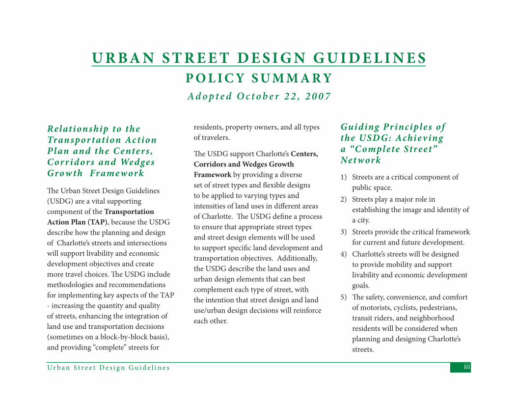
Th e Urban Street Design Guidelines (USDG) are a vital supporting component of the Transportation Action Plan (TAP), because the USDG describe how the planning and design of Charlotte’s streets and intersections will support livability and economic development objectives and create more travel choices. Th e USDG include methodologies and recommendations for implementing key aspects of the TAP - increasing the quantity and quality of streets, enhancing the integration of land use and transportation decisions (sometimes on a block-by-block basis), and providing “complete” streets for
Relation ship to the Tran spor tation Ac tionPlan and the Centers ,Cor r idors and WedgesGrow th Frame work
residents, property owners, and all types of travelers.
Th e USDG support Charlotte’s Centers, Corridors and Wedges Growth Framework by providing a diverse set of street types and fl exible designs to be applied to varying types and intensities of land uses in diff erent areas of Charlotte. Th e USDG defi ne a process to ensure that appropriate street types and street design elements will be used to support specifi c land development and transportation objectives. Additionally, the USDG describe the land uses and urban design elements that can best complement each type of street, with the intention that street design and land use/urban design decisions will reinforce each other.
Guiding Pr inciples of the USD G: Achie v ing a “Complete Street” Net work1) Streets are a critical component of
public space.2) Streets play a major role in
establishing the image and identity of a city.
3) Streets provide the critical framework for current and future development.
4) Charlotte’s streets will be designed to provide mobility and support livability and economic development goals.
5) Th e safety, convenience, and comfort of motorists, cyclists, pedestrians, transit riders, and neighborhood residents will be considered when planning and designing Charlotte’s streets.
Ur b a n S t r e e t D e s i g n G u i d e l i n e siv
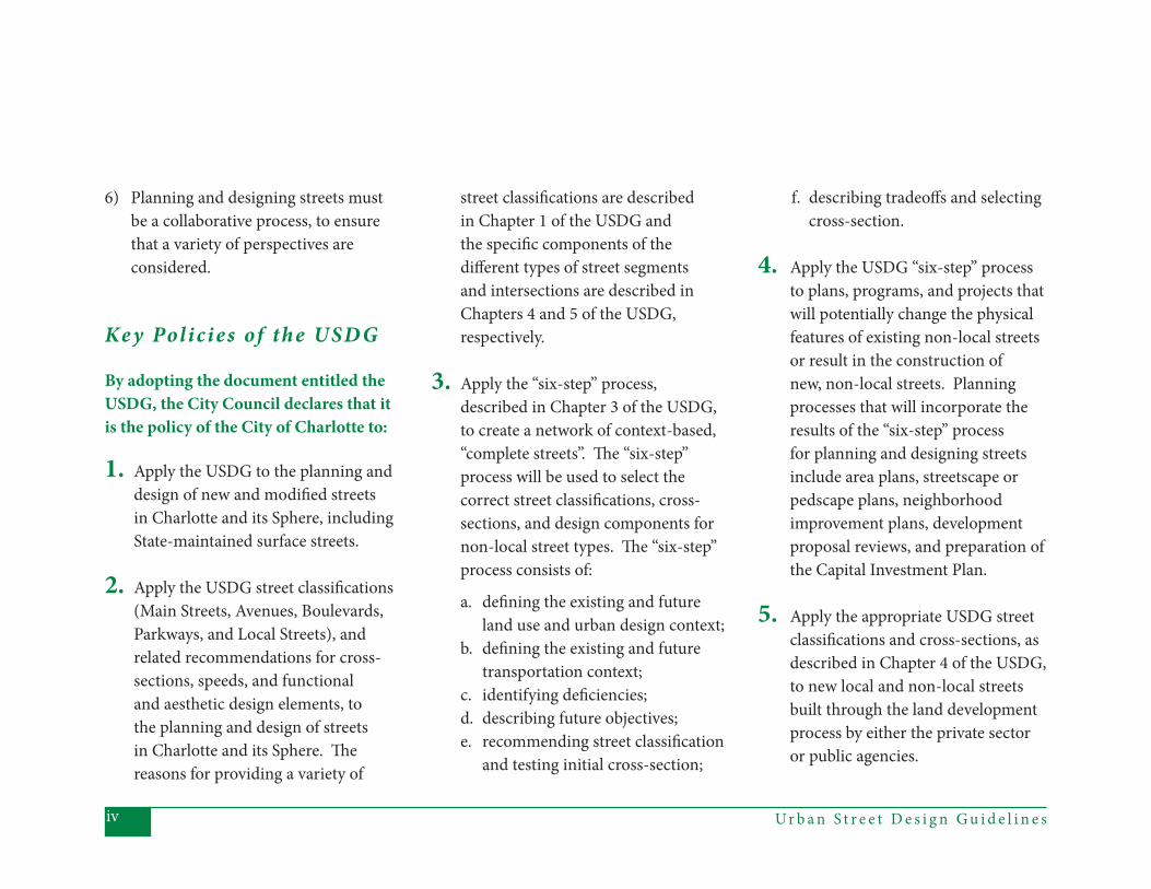
6) Planning and designing streets must be a collaborative process, to ensure that a variety of perspectives are considered.
Ke y Polic ies of the USD G
By adopting the document entitled the USDG, the City Council declares that it is the policy of the City of Charlotte to:
1. Apply the USDG to the planning and design of new and modifi ed streets in Charlotte and its Sphere, including State-maintained surface streets.
2. Apply the USDG street classifi cations (Main Streets, Avenues, Boulevards, Parkways, and Local Streets), and related recommendations for cross-sections, speeds, and functional and aesthetic design elements, to the planning and design of streets in Charlotte and its Sphere. Th e reasons for providing a variety of
street classifi cations are described in Chapter 1 of the USDG and the specifi c components of the diff erent types of street segments and intersections are described in Chapters 4 and 5 of the USDG, respectively.
3. Apply the “six-step” process, described in Chapter 3 of the USDG, to create a network of context-based, “complete streets”. Th e “six-step” process will be used to select the correct street classifi cations, cross-sections, and design components for non-local street types. Th e “six-step” process consists of:
a. defi ning the existing and future land use and urban design context;
b. defi ning the existing and future transportation context;
c. identifying defi ciencies;d. describing future objectives;e. recommending street classifi cation
and testing initial cross-section;
f. describing tradeoff s and selecting cross-section.
4. Apply the USDG “six-step” process to plans, programs, and projects that will potentially change the physical features of existing non-local streets or result in the construction of new, non-local streets. Planning processes that will incorporate the results of the “six-step” process for planning and designing streets include area plans, streetscape or pedscape plans, neighborhood improvement plans, development proposal reviews, and preparation of the Capital Investment Plan.
5. Apply the appropriate USDG street classifi cations and cross-sections, as described in Chapter 4 of the USDG, to new local and non-local streets built through the land development process by either the private sector or public agencies.
vUr b a n S t r e e t D e s i g n G u i d e l i n e s
6. Implement processes to ensure that the USDG street classifi cations and designs derived through the “six-step” process result in mutually reinforcing land use and transportation decisions. Implementation will include: amending the TAP Street Classifi cation Map to refl ect the specifi c recommendations defi ned during area or neighborhood plans, and establishing priorities for adopting new or updating existing land use plans to refl ect the most up-to-date land use objectives for streets classifi ed according to the USDG.
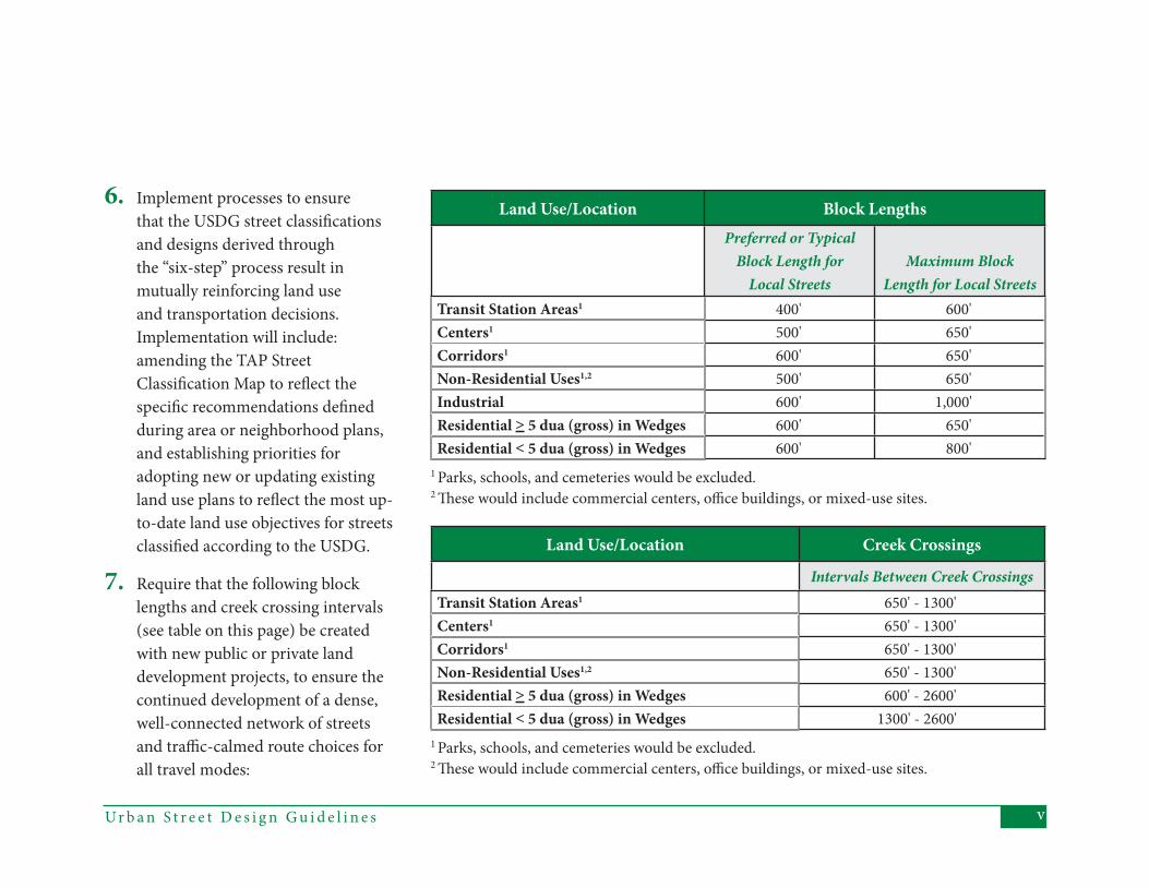
7. Require that the following block lengths and creek crossing intervals (see table on this page) be created with new public or private land development projects, to ensure the continued development of a dense, well-connected network of streets and traffi c-calmed route choices for all travel modes:
Land Use/Location Block LengthsPreferred or Typical
Block Length for Local Streets
Maximum Block Length for Local Streets
Transit Station Areas1 400' 600'Centers1 500' 650'Corridors1 600' 650'Non-Residential Uses1,2 500' 650'Industrial 600' 1,000'Residential > 5 dua (gross) in Wedges 600' 650'Residential < 5 dua (gross) in Wedges 600' 800'
1 Parks, schools, and cemeteries would be excluded.2 Th ese would include commercial centers, offi ce buildings, or mixed-use sites.
Land Use/Location Creek Crossings
Intervals Between Creek CrossingsTransit Station Areas1 650' - 1300'Centers1 650' - 1300'Corridors1 650' - 1300'Non-Residential Uses1,2 650' - 1300'Residential > 5 dua (gross) in Wedges 600' - 2600'Residential < 5 dua (gross) in Wedges 1300' - 2600'
1 Parks, schools, and cemeteries would be excluded.2 Th ese would include commercial centers, offi ce buildings, or mixed-use sites.
Ur b a n S t r e e t D e s i g n G u i d e l i n e svi
While the expectation is that Local Streets will be built at the preferred or typical block lengths described above, it may not always be feasible or desirable to construct all streets or block lengths exactly as described above. Th e process for defi ning the factors that would aff ect or infl uence the construction of stub streets or creek crossings, or the provision of dedicated rights-of-way is described in the next section of this preamble.
8. Expand Charlotte’s street tree canopy by providing planting strips wide enough for healthy, large-maturing street trees. Details (and guidelines for fl exible applications) are described in Chapter 4, but generally:
a. on retrofi ts to existing streets, whether built by the City or by developers, create 8' planting strips, planted with large-maturing trees;
b. for newly-constructed streets, whether built by the City or by developers, create 8’ planting strips, planted with large-maturing trees, except in the case of new, Medium Local Streets. For this category of streets, developers could choose between 8' planting strips and large-maturing street trees or 6’ planting strips and small or medium-maturing trees, but the site developer and staff would be expected to justify why they are not implementing 8' planting strips.
9. Apply the bicycle, pedestrian, and
motorist Level-of-Service (LOS) comparisons (including a 2-hour
AM or PM peak period congestion analysis), as described in Chapter 5 and Appendices A and B of the USDG, to the planning and design of signalized intersections, to ensure that the physical designs of intersections refl ect their street
classifi cations and surrounding context.
10. Apply the design recommenda-tions described in Chapter 5 and Appendices A-C of the USDG to all (signalized or unsignalized) intersections, whether constructed or modifi ed by the City or by private developers. Th e design recommendations will aff ect the number and width of travel lanes, inclusion of bicycle facilities, treatments for pedestrian crossings, traffi c control devices and operation, pavement markings, and curb radii.
11. Apply the USDG sidewalk recommendations. Th ese are described in detail in Chapter 4 of the USDG, but in general:
a. the minimum sidewalk width in the City will be 5',
b. the minimum sidewalk width
viiUr b a n S t r e e t D e s i g n G u i d e l i n e s
along Avenues and Boulevards will be 6',
c. a separate pathway outside the right-of-way of Parkways will be a design priority, and
d. minimum sidewalk widths of 8'-10' will be created in areas where there likely would be high er pedestrian volumes, due to the existing or planned land uses.
12. Continue to expand Charlotte’s bicycle network by, in general, providing bike lanes on the higher-volume, higher-speed streets and signed bike routes on low-volume, low-speed streets. As described in greater detail in Chapter 4 of the USDG:
a. Bike lanes will typically be incorporated into new or existing Avenues and Boulevards.
b. Main Streets and Local Streets will not typically include bike lanes.
design components for all new or retrofi tted streets meet the USDG recommendations.
15. By 2008, prepare supplements to the USDG for “special streets” (including, but not limited to, green streets, culs-de-sac, one-way streets, alleys, and private streets).
16. By 2008, update CDOT’s Driveway Regulations and Sight Distance Policy, and revise the City’s pavement standards, with structural components linked to the USDG classifi cations.
17. By 2008, evaluate and defi ne feasible changes to horizontal and vertical curvature requirements, to support traffi c calming, reduce the impacts of mass grading, and minimize negative impacts of stream crossings.
c. Parkways will incorporate bike pathways outside of the Parkway right-of-way or in one or more nearby, connected Local Streets.
d. Th e bicycle travel network will include signed bike routes on Local Streets connecting to bike lanes on Avenues, Boulevards, or Parkways.
e. Design teams will justify why bike lanes would not be included for any street segment where bike lanes would generally be expected.
13. Incorporate traffi c calming components or treatments (as described in CDOT’s Traffi c Calming Report) into the design of new or retrofi tted streets. Require “slow points” on new Local Streets.
14. Update all necessary and appropriate codes, standards, and ordinances to ensure that

1Ur b a n S t r e e t D e s i g n G u i d e l i n e s
1 . R E D E F I N I N G C HA R L O T T E ’ S S T R E E T S
T he Urban Street Design Guidelines described in this document present
a comprehensive approach to designing new and modifi ed streets within Char-lotte’s designated Sphere of Infl uence. Th e Guidelines will allow us to provide better streets throughout Charlotte – streets that refl ect the best aspects of the streets built in the past, and that will provide more capacity and safe and com-fortable travel for motorists, pedestrians, bicyclists, and transit riders.
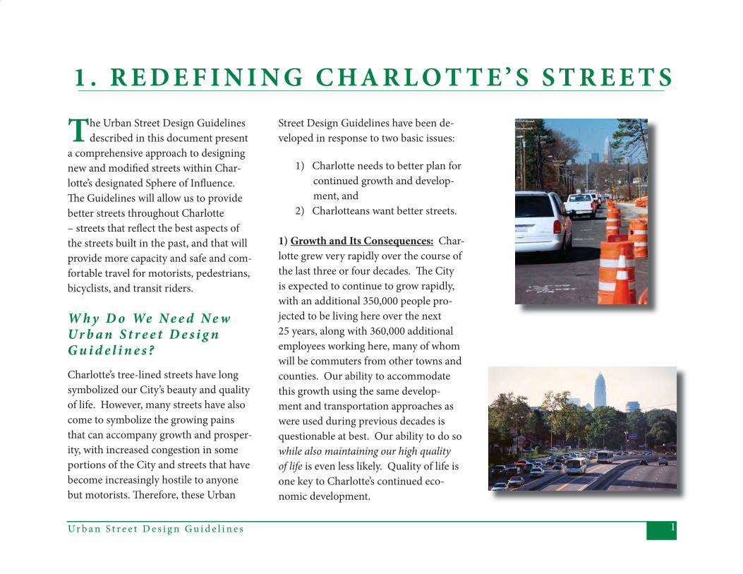
W h y D o We N e e d N e w Ur b a n S t r e e t D e s i g n G u i d e l i n e s ?Charlotte’s tree-lined streets have long symbolized our City’s beauty and quality of life. However, many streets have also come to symbolize the growing pains that can accompany growth and prosper-ity, with increased congestion in some portions of the City and streets that have become increasingly hostile to anyone but motorists. Th erefore, these Urban
Street Design Guidelines have been de-veloped in response to two basic issues:
1) Charlotte needs to better plan for continued growth and develop- ment, and 2) Charlotteans want better streets.
1) Growth and Its Consequences: Char-lotte grew very rapidly over the course of the last three or four decades. Th e City is expected to continue to grow rapidly, with an additional 350,000 people pro-jected to be living here over the next 25 years, along with 360,000 additional employees working here, many of whom will be commuters from other towns and counties. Our ability to accommodate this growth using the same develop-ment and transportation approaches as were used during previous decades is questionable at best. Our ability to do so while also maintaining our high quality of life is even less likely. Quality of life is one key to Charlotte’s continued eco-nomic development.
Ur b a n S t r e e t D e s i g n G u i d e l i n e s2
Th e Urban Street Design Guidelines are intended to help the City accommodate growth in several ways. Th ey support a variety of City policies, including the Centers, Corridors and Wedges growth framework and the recently adopted Transportation Action Plan, which describes the transportation-related policies and programs needed to help Charlotte maintain its many advantages as it continues to grow.
Th e Guidelines will help achieve the emerging vision for Charlotte (summa-rized in the box on the right) by sup-porting the goal of more compact and focused growth, and by off ering more transportation choices. Th ese are com-plementary intentions because compact development makes providing trans-portation choices easier and providing transportation choices makes compact development more liveable and viable.
“Transportation choices” are created both by providing more connections - more route choices for all travelers - and by building streets that are easier to use by more types of travelers – by people who want to walk, ride transit, or ride
bicycles. Generally, more connections and better provision for all modes will help increase our transportation system’s capacity, further sustaining growth. Providing transportation choices also helps address an important environ-mental consequence of growth – poor air quality. In Charlotte, like many cit-ies, our major air pollution problem is
ozone, which is created when nitrogen oxides and volatile organic compounds combine in sunlight and stagnant air. In Mecklenburg County, nitrogen oxides are emitted mostly by motor vehicles. Th ere-fore, the sheer number of cars and the miles they travel have a great impact on our air quality. In addition to the health eff ects of poor air quality, this also rep-
3Ur b a n S t r e e t D e s i g n G u i d e l i n e s
resents a signifi cant potential cost, since our region must remain in compliance with federal standards on certain pollut-ants, including ozone. Failure to comply can result in withholding of federal fund-ing for transportation projects, which can further impact our city’s ability to sustain development. Air quality, there-fore, is an important component of both quality of life and continued economic development.
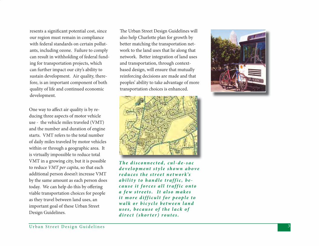
T h e d i s c o n n e c t e d , c u l - d e - s a c d e v e l o p m e n t s t y l e s h o w n a b o v e r e d u c e s t h e s t r e e t n e t w o r k’s a b i l i t y t o h a n d l e t r a f f i c , b e -c a u s e i t f o r c e s a l l t r a f f i c o n t o a f e w s t r e e t s . I t a l s o m a k e s i t m o r e d i f f i c u l t f o r p e o p l e t o w a l k o r b i c y c l e b e t w e e n l a n d u s e s , b e c a u s e o f t h e l a c k o f d i r e c t ( s h o r t e r ) r o u t e s .
One way to aff ect air quality is by re-ducing three aspects of motor vehicle use - the vehicle miles traveled (VMT) and the number and duration of engine starts. VMT refers to the total number of daily miles traveled by motor vehicles within or through a geographic area. It is virtually impossible to reduce total VMT in a growing city, but it is possible to reduce VMT per capita, so that each additional person doesn’t increase VMT by the same amount as each person does today. We can help do this by off ering viable transportation choices for people as they travel between land uses, an important goal of these Urban Street Design Guidelines.
Th e Urban Street Design Guidelines will also help Charlotte plan for growth by better matching the transportation net-work to the land uses that lie along that network. Better integration of land uses and transportation, through context-based design, will ensure that mutually reinforcing decisions are made and that peoples’ ability to take advantage of more transportation choices is enhanced.
Ur b a n S t r e e t D e s i g n G u i d e l i n e s4
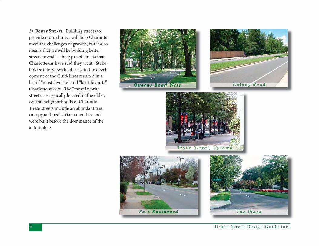
2) Better Streets: Building streets to provide more choices will help Charlotte meet the challenges of growth, but it also means that we will be building better streets overall – the types of streets that Charlotteans have said they want. Stake-holder interviews held early in the devel-opment of the Guidelines resulted in a list of “most favorite” and “least favorite” Charlotte streets. Th e “most favorite” streets are typically located in the older, central neighborhoods of Charlotte. Th ese streets include an abundant tree canopy and pedestrian amenities and were built before the dominance of the automobile.
5Ur b a n S t r e e t D e s i g n G u i d e l i n e s
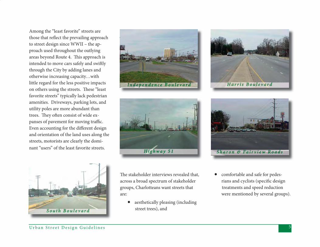
Among the “least favorite” streets are those that refl ect the prevailing approach to street design since WWII – the ap-proach used throughout the outlying areas beyond Route 4. Th is approach is intended to move cars safely and swift ly through the City by adding lanes and otherwise increasing capacity…with little regard for the less positive impacts on others using the streets. Th ese “least favorite streets” typically lack pedestrian amenities. Driveways, parking lots, and utility poles are more abundant than trees. Th ey oft en consist of wide ex-panses of pavement for moving traffi c. Even accounting for the diff erent design and orientation of the land uses along the streets, motorists are clearly the domi-nant “users” of the least favorite streets.
Th e stakeholder interviews revealed that, across a broad spectrum of stakeholder groups, Charlotteans want streets that are:
• aesthetically pleasing (including street trees), and
• comfortable and safe for pedes- rians and cyclists (specifi c design
treatments and speed reduction were mentioned by several groups).
Ur b a n S t r e e t D e s i g n G u i d e l i n e s6
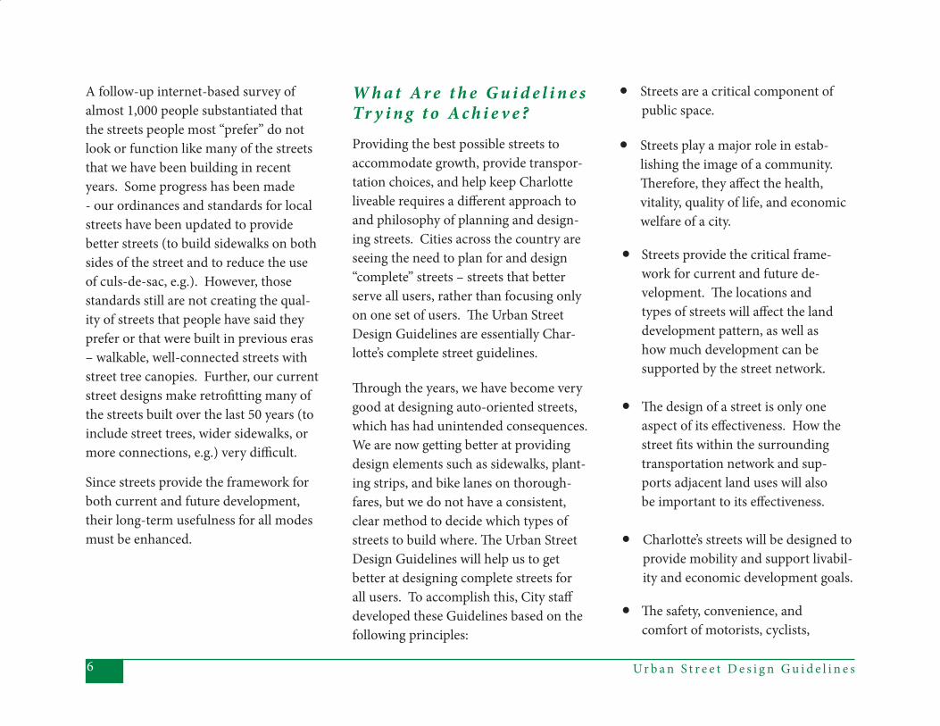
• Streets are a critical component of public space.
• Streets play a major role in estab - lishing the image of a community. Th erefore, they aff ect the health, vitality, quality of life, and economic welfare of a city.
• Streets provide the critical frame-work for current and future de-
velopment. Th e locations and types of streets will aff ect the land development pattern, as well as how much development can be supported by the street network.
• Th e design of a street is only one aspect of its eff ectiveness. How the
street fi ts within the surrounding transportation network and sup-
ports adjacent land uses will also be important to its eff ectiveness.
• Charlotte’s streets will be designed to provide mobility and support livabil- ity and economic development goals.
• Th e safety, convenience, and comfort of motorists, cyclists,
A follow-up internet-based survey of almost 1,000 people substantiated that the streets people most “prefer” do not look or function like many of the streets that we have been building in recent years. Some progress has been made - our ordinances and standards for local streets have been updated to provide better streets (to build sidewalks on both sides of the street and to reduce the use of culs-de-sac, e.g.). However, those standards still are not creating the qual-ity of streets that people have said they prefer or that were built in previous eras – walkable, well-connected streets with street tree canopies. Further, our current street designs make retrofi tting many of the streets built over the last 50 years (to include street trees, wider sidewalks, or more connections, e.g.) very diffi cult.
Since streets provide the framework for both current and future development, their long-term usefulness for all modes must be enhanced.
W h a t A r e t h e G u i d e l i n e s Tr y i n g t o A c h i e v e ? Providing the best possible streets to accommodate growth, provide transpor-tation choices, and help keep Charlotte liveable requires a diff erent approach to and philosophy of planning and design-ing streets. Cities across the country are seeing the need to plan for and design “complete” streets – streets that better serve all users, rather than focusing only on one set of users. Th e Urban Street Design Guidelines are essentially Char-lotte’s complete street guidelines.
Th rough the years, we have become very good at designing auto-oriented streets, which has had unintended consequences. We are now getting better at providing design elements such as sidewalks, plant-ing strips, and bike lanes on thorough-fares, but we do not have a consistent, clear method to decide which types of streets to build where. Th e Urban Street Design Guidelines will help us to get better at designing complete streets for all users. To accomplish this, City staff developed these Guidelines based on the following principles:
7Ur b a n S t r e e t D e s i g n G u i d e l i n e s
pedestrians, transit users, and mem-bers of the surrounding community will be considered when planning and designing Charlotte’s streets.
• Streets should be designed to en- courage Charlotteans to make trips by means other than cars, thereby positively impacting congestion, air quality, and the health of our citizens.
• Planning and designing streets must be a collaborative process,
because it is necessary that deci-sions about the street be made with a variety of interests and perspectives represented.
Based on these principles, the recom-mendations contained within these Ur-ban Street Design Guidelines refl ect the following basic goals:
1) Support economic development and quality of life – by providing more transportation capacity, while creating more user-friendly streets overall.
2) Provide more and safer transporta- tion choices – by creating a better- connected network (route choices) and building streets for a variety of users (mode choices).
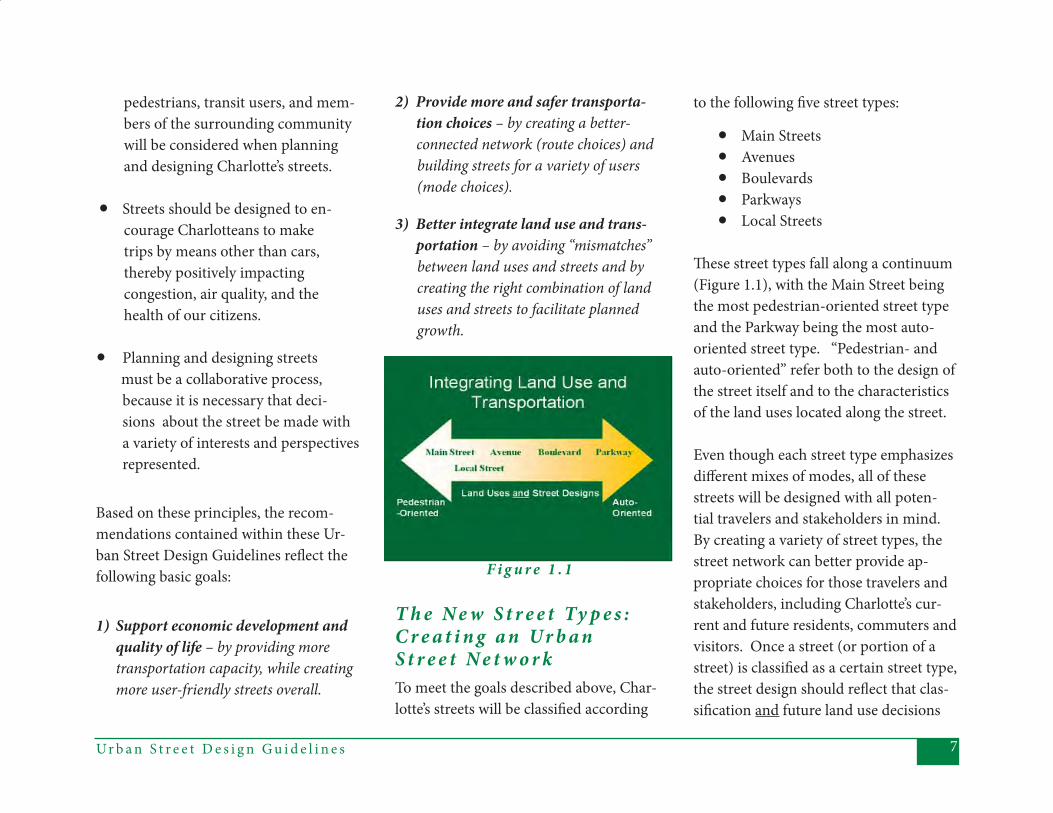
3) Better integrate land use and trans- portation – by avoiding “mismatches” between land uses and streets and by creating the right combination of land uses and streets to facilitate planned growth.
T h e N e w S t r e e t Ty p e s : C r e a t i n g a n Ur b a n S t r e e t N e t w o r kTo meet the goals described above, Char-lotte’s streets will be classifi ed according
to the following fi ve street types:
• Main Streets• Avenues• Boulevards• Parkways• Local Streets
Th ese street types fall along a continuum (Figure 1.1), with the Main Street being the most pedestrian-oriented street type and the Parkway being the most auto-oriented street type. “Pedestrian- and auto-oriented” refer both to the design of the street itself and to the characteristics of the land uses located along the street. Even though each street type emphasizes diff erent mixes of modes, all of these streets will be designed with all poten-tial travelers and stakeholders in mind. By creating a variety of street types, the street network can better provide ap-propriate choices for those travelers and stakeholders, including Charlotte’s cur-rent and future residents, commuters and visitors. Once a street (or portion of a street) is classifi ed as a certain street type, the street design should refl ect that clas-sifi cation and future land use decisions
F i g u r e 1 . 1

Ur b a n S t r e e t D e s i g n G u i d e l i n e s8
along the street should also refl ect that classifi cation. Street design decisions and land use decisions should be mutually reinforcing, to create eff ective synergy between streets and land uses.
While a complete description of these street types and land use characteristics is provided in Chapter 4, the following are brief descriptions of each street type:
• Main Streets are “destination streets”. Th ey provide access to and function as centers of civic, social, and com- mercial activity. Main Streets are designed to provide the highest level of comfort, security and access for pedestrians. Development along Main Streets is dense and focused toward the pedestrian realm.
Land uses on Main Streets are typi-cally mixed and are generators and attractors of pedestrian activity. Be-cause of their specialized function
and context, Main Streets will repre- sent a relatively small portion of Charlotte’s overall street network.
• Boulevards are designed to move larger numbers of vehicles (as through traffi c) from one part of the city to another and to other lower level streets in the network. • Avenues can serve a diverse set of
functions in a wide variety of land use contexts. Th erefore, they are the most common (non-local) street type in our city. Th ey provide ac- cess from neighborhoods to com- mercial areas, between major inter- city destinations and, in some cases, through neighborhoods. Avenues serve an important function in providing transportation choices,
because they are designed to pro- vide a balance of service for all modes of transport. Th ey provide for high quality pedestrian access, high levels of transit accessibility, bi- cycle accommodations such as bike lanes, yet they may also carry sig- nifi cant automobile traffi c. Most thoroughfares in our street network would be classifi ed as Avenues. Th e collector/connector function can also be served by some Avenue cross- sections.
9Ur b a n S t r e e t D e s i g n G u i d e l i n e s
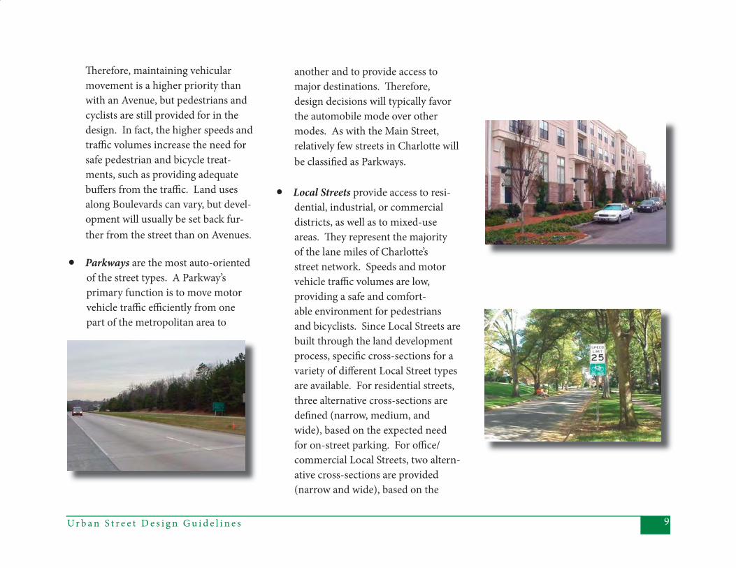
• Parkways are the most auto-oriented of the street types. A Parkway’s
primary function is to move motor vehicle traffi c effi ciently from one part of the metropolitan area to
another and to provide access to major destinations. Th erefore, design decisions will typically favor the automobile mode over other modes. As with the Main Street, relatively few streets in Charlotte will be classifi ed as Parkways.
• Local Streets provide access to resi- dential, industrial, or commercial districts, as well as to mixed-use areas. Th ey represent the majority of the lane miles of Charlotte’s street network. Speeds and motor vehicle traffi c volumes are low, providing a safe and comfort- able environment for pedestrians and bicyclists. Since Local Streets are built through the land development process, specifi c cross-sections for a variety of diff erent Local Street types are available. For residential streets, three alternative cross-sections are defi ned (narrow, medium, and wide), based on the expected need for on-street parking. For offi ce/ commercial Local Streets, two altern- ative cross-sections are provided (narrow and wide), based on the
Th erefore, maintaining vehicular movement is a higher priority than with an Avenue, but pedestrians and cyclists are still provided for in the design. In fact, the higher speeds and traffi c volumes increase the need for safe pedestrian and bicycle treat- ments, such as providing adequate buff ers from the traffi c. Land uses along Boulevards can vary, but devel- opment will usually be set back fur- ther from the street than on Avenues.
Ur b a n S t r e e t D e s i g n G u i d e l i n e s10
expected need for on-street parking. Th e general intent is to keep the pavement on these streets as narrow as possible.
H o w D o t h e s e G u i d e l i n e s R e l a t e t o O t h e r Tr a n s -p o r t a t i o n P l a n n i n g A c t i v i t i e s ?With the 2006 adoption of the Trans-portation Action Plan (TAP), the City of Charlotte established a comprehensive plan for providing the necessary trans-portation elements to sustain Charlotte’s growth and quality of life. Th e TAP describes the policies, programs, and projects that will be implemented over the next twenty-fi ve years to ensure that Charlotteans have the most travel choices available to them as the City grows. Th e Urban Street Design Guidelines, by de-scribing how Charlotte’s streets should be designed, is a fundamental component for implementing the TAP and providing the necessary street network for decades to come.
In addition to the TAP, the Urban Street Design Guidelines will relate to other planning processes, including the exist-ing State-required Th oroughfare Plan and emerging Comprehensive Trans-portation Plan. Both of these planning approaches are based on the functional classifi cation of streets. Th e new street types described in the Guidelines are intended to work as “overlays” to exist-ing street classifi cations. Th is means that, while a street might be identifi ed, for example, as a major thoroughfare from a functional standpoint, it might be labeled an Avenue from the Urban Street Design standpoint. Th e Urban Street De-sign Guidelines classifi cation will then aff ect the planning and ultimate design of the street. An important point is that a given street may be classifi ed diff erent-ly on diff erent segments, for example, as an Avenue for one portion of its length and as a Boulevard for another. Since most thoroughfares traverse more than one land use context, the Urban Street Design classifi cations will allow the ulti-mate design of the street to refl ect those various contexts.
Th e use of this “overlay” approach will likely need to be refi ned somewhat, as NCDOT moves away from its traditional thoroughfare planning process. Recent attempts to make state road planning better refl ect multi-modal and context-based design have resulted in a new type of plan to replace the Th oroughfare Plan – the Comprehensive Transporta-tion Plan (CTP). Th e CTP will use some diff erent classifi cation schemes than the Th oroughfare Plan. Th e Urban Street Design Guidelines classifi cation system should work in tandem with the CTP, with the major diff erence being the street function anticipated by NCDOT or the city.
By having a set of street types that better refl ect and complement a variety of land use contexts, Charlotteans and visitors can expect to fi nd viable transportation choices as they travel through the City, something that has become increasingly diffi cult in recent decades. Further, by defi ning and implementing street designs to meet the intent of the diff erent street types, we have the best chance of meeting
11Ur b a n S t r e e t D e s i g n G u i d e l i n e s
the multiple and sometimes confl icting objectives of the diff erent users of our streets. Charlotte’s Urban Street Design Guidelines will, over time, result in a well-connected network of “complete” streets that function well for all users and that complement and preserve the communities and neighborhoods they connect.
C o n t e n t o f t h e G u i d e l i n e sTh e following chapters are intended to provide a comprehensive treatment of Charlotte’s approach to street design. Each chapter provides a separate, stand-alone piece of information pertaining to street design, but each chapter also relates to the others. In this fashion, the Guidelines provide both the “big picture” of developing Charlotte’s desired street network and the detailed guidelines necessary to design individual street seg-ments and intersections. Th e remaining chapters include:
• Chapter 2: Designing Streets for Multiple Users. Th is chapter
presents a thorough treatment of the need for and approaches to evaluating the tradeoff s among
competing users and uses of the street right-of-way.
• Chapter 3: Applying the Guide-lines. Th is chapter defi nes a rec-ommended approach to applying the Guidelines, particularly in the case of non-local streets.
• Chapter 4: Segments. Th is chapter contains detailed infor- mation (text and diagrams) de- scribing how to design the por- tions of the streets between the intersections.
• Chapter 5: Intersections. Th is chapter contains detailed infor- mation (text and diagrams) de-
scribing how to design various types of intersections.
• Chapter 6: Glossary. Th is chap- ter includes defi nitions or de- scriptions of diff erent design ele- ments, their intended purposes,
and how they are best applied. • Appendices. Appendices A-C
provide additional details about the application of the new approaches outlined in the Guidelines.
R e l a t e d C o n t e n t I t e m s t o b e D e v e l o p e dAlthough the current document includes comprehensive coverage of planning and designing Charlotte’s street network, there are some additional, related items that will be developed over the com-ing months and treated as supplements to the Urban Street Design Guidelines. Some of these are items that will require additional stakeholder comment or will be treated as part of the implementation of the Transportation Action Plan or the adopted Urban Street Design Guidelines. Th ese additional items include:
• a section on designing “special” street types, such as green streets, alleys, culs-de-sac, one-way streets and private streets;
Ur b a n S t r e e t D e s i g n G u i d e l i n e s12
• more details on “connector” streets, including development of a connector map;
• a section describing access con- trol, including driveway designs;
• updates to the City’s Sight Distance Policy and pavement standards; and
• an appendix describing horizontal and vertical curvature allowances on Local Streets.
13Ur b a n S t r e e t D e s i g n G u i d e l i n e s
2 . D E S I G N I N G S T R E E T S F O R M U LT I P L E U S E R S
Th ese Urban Street Design Guidelines are intended to ensure that the best aspects of Charlotte’s transportation network are re-created as the City and its street network continue to evolve. Th is means that the various street design elements (described in Chapters 4 and 5) must be applied in the right mixes and in the right places. Th e process for planning and designing streets must also be sensitive to both the land use context and to the needs of the various users of a street. Th is chapter provides information about how diff erent travelers may expect diff erent things from a street. Equally important, the following chapter (Chap-ter 3) describes a method for applying the Guidelines so that any tradeoff s are evaluated fairly for all stakeholders.
Assessing Tradeoff s: Who is Using the Street?Th e fi rst step towards designing streets that provide viable transportation op-tions is to understand that diff erent users of the street will likely have diff erent ex-
pectations of what makes a “good” street. A street design solution that works well for a motorist, for example, may or may not work well for a pedestrian or a bicy-clist. Th is is one reason many American cities are becoming more concerned about providing “complete streets.” Fur-ther, even if every “ideal” design element for all of the travelers on a street were provided, then the resulting street might not satisfy the expectations of the people who live or work along it. Th ese diff erent stakeholders and their expectations for a street can complicate the design process, which is one reason Charlotte has devel-oped these Guidelines.
Prior to the 1990s, street design was treated as a relatively straightforward task, with a pre-set menu of (oft en auto-oriented) cross-sections for streets with pre-defi ned functional classifi cations. Th at approach is changing in many cities, for a variety of reasons. One reason is that right-of-way becomes constrained as cities develop, and “standard” cross-
sections are less likely to fi t within the available right-of-way, particularly for retrofi t projects. Another reason is that there is increasing concern about provid-ing facilities that can be used by people other than motorists. In these cases, designing the street has had to become a more analytic process - one that considers the various user perspectives and the sur-rounding land use context, in addition to the street function.
Th ese Guidelines are intended to ensure a process that clearly, consistently, and com-prehensively considers the needs of mo-torists, pedestrians, and bicyclists when planning and designing streets. All streets should be evaluated in terms of how they aff ect many diff erent groups, including:
• motorists, • pedestrians (including transit riders), • transit operators,• bicyclists, and • people living, working, or otherwise
using the adjacent land uses.
Ur b a n S t r e e t D e s i g n G u i d e l i n e s14
Each of these groups has expectations about how a given street should func-tion and, therefore, how it should be designed. Th e following examples describe various street users’ perspectives and how they might be addressed in the design process.
What Do Motorists Want From Streets?When a motorist expresses a concern or makes a request related to streets, it oft en stems from congestion or safety con-cerns. Motorists might expect streets to be widened and signalized intersections to be timed to enhance their own travel times, for example. Th ey may also ask that the number of stop-controlled inter-sections on local streets be reduced, so that they can maintain free fl ow through neighborhoods. Th is interest in design features that motorists feel provide them “safe and effi cient” travel has also long been the primary concern of highway designers.
To meet motorists’ expectations for safe and effi cient travel, perfect conditions over the street network would include:
• minimal travel delays,• minimal confl icts (aff ecting both delay and safety), and• consistently designed facilities.
For the most part, though, urban streets cannot provide this combination of conditions except perhaps on freeways or other access-controlled roadways. Even then, travel delay and potential for con-fl icts with other vehicles will vary by time of day. Furthermore, consistent design is not only diffi cult to provide on urban streets, but probably not even desirable for other reasons (it is at odds with the concept of context-sensitive design).
Although providing all of the favorable conditions for motorists described above is diffi cult, there are ways to achieve some of the motorists’ preferences, either through construction or operational
changes. Th ese approaches include:
• adding through or turn lanes to increase capacity, which can help reduce delay, at least temporarily;
• making operational changes, such as providing more green- signal time to the street with the higher traffi c volumes, which can reduce the wait time at signalized intersections for those motorists on the higher volume street while increasing the wait time for
motorists entering from the lower volume side street;
• constructing grade-separated intersections and roundabouts, rather than signal or stop con- trolled intersections, which can also limit delay and increase capacity; and
• using bus pullouts to separate stopping transit vehicles from the
travel lane and, therefore, to help reduce delay.
15Ur b a n S t r e e t D e s i g n G u i d e l i n e s
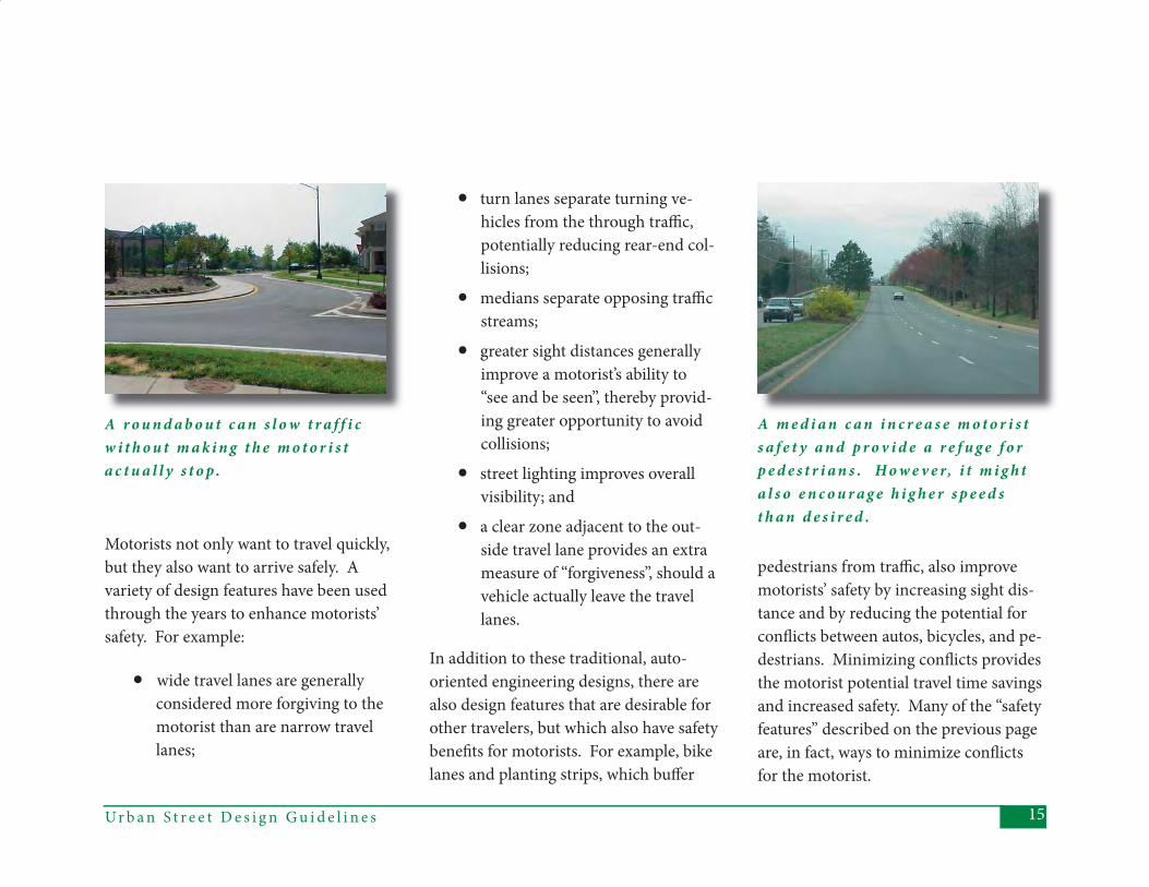
A r o u n d a b o u t c a n s l o w t r a f f i c w i t h o u t m a k i n g t h e m o t o r i s t a c t u a l l y s t o p .
Motorists not only want to travel quickly, but they also want to arrive safely. A variety of design features have been used through the years to enhance motorists’ safety. For example:
• wide travel lanes are generally considered more forgiving to the motorist than are narrow travel lanes;
• turn lanes separate turning ve- hicles from the through traffi c, potentially reducing rear-end col- lisions;
• medians separate opposing traffi c streams;
• greater sight distances generally improve a motorist’s ability to “see and be seen”, thereby provid- ing greater opportunity to avoid collisions;
• street lighting improves overall visibility; and
• a clear zone adjacent to the out- side travel lane provides an extra measure of “forgiveness”, should a vehicle actually leave the travel lanes.
In addition to these traditional, auto-oriented engineering designs, there are also design features that are desirable for other travelers, but which also have safety benefi ts for motorists. For example, bike lanes and planting strips, which buff er
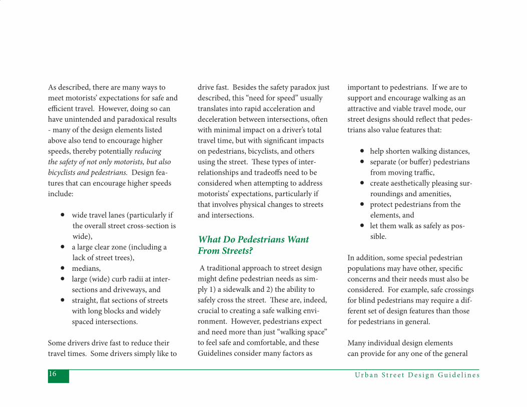
A m e d i a n c a n i n c r e a s e m o t o r i s t s a f e t y a n d p r o v i d e a r e f u g e f o r p e d e s t r i a n s . H o w e v e r, i t m i g h t a l s o e n c o u r a g e h i g h e r s p e e d s t h a n d e s i r e d .
pedestrians from traffi c, also improve motorists’ safety by increasing sight dis-tance and by reducing the potential for confl icts between autos, bicycles, and pe-destrians. Minimizing confl icts provides the motorist potential travel time savings and increased safety. Many of the “safety features” described on the previous page are, in fact, ways to minimize confl icts for the motorist.
Ur b a n S t r e e t D e s i g n G u i d e l i n e s16
As described, there are many ways to meet motorists’ expectations for safe and effi cient travel. However, doing so can have unintended and paradoxical results - many of the design elements listed above also tend to encourage higher speeds, thereby potentially reducing the safety of not only motorists, but also bicyclists and pedestrians. Design fea-tures that can encourage higher speeds include:
• wide travel lanes (particularly if the overall street cross-section is wide), • a large clear zone (including a lack of street trees), • medians, • large (wide) curb radii at inter- sections and driveways, and • straight, fl at sections of streets with long blocks and widely spaced intersections.
Some drivers drive fast to reduce their travel times. Some drivers simply like to
drive fast. Besides the safety paradox just described, this “need for speed” usually translates into rapid acceleration and deceleration between intersections, oft en with minimal impact on a driver’s total travel time, but with signifi cant impacts on pedestrians, bicyclists, and others using the street. Th ese types of inter-relationships and tradeoff s need to be considered when attempting to address motorists’ expectations, particularly if that involves physical changes to streets and intersections.
What Do Pedestrians Want From Streets? A traditional approach to street design might defi ne pedestrian needs as sim-ply 1) a sidewalk and 2) the ability to safely cross the street. Th ese are, indeed, crucial to creating a safe walking envi-ronment. However, pedestrians expect and need more than just “walking space” to feel safe and comfortable, and these Guidelines consider many factors as
important to pedestrians. If we are to support and encourage walking as an attractive and viable travel mode, our street designs should refl ect that pedes-trians also value features that:
• help shorten walking distances,• separate (or buff er) pedestrians from moving traffi c,• create aesthetically pleasing sur- roundings and amenities, • protect pedestrians from the elements, and• let them walk as safely as pos- sible.
In addition, some special pedestrian populations may have other, specifi c concerns and their needs must also be considered. For example, safe crossings for blind pedestrians may require a dif-ferent set of design features than those for pedestrians in general.
Many individual design elements can provide for any one of the general
17Ur b a n S t r e e t D e s i g n G u i d e l i n e s
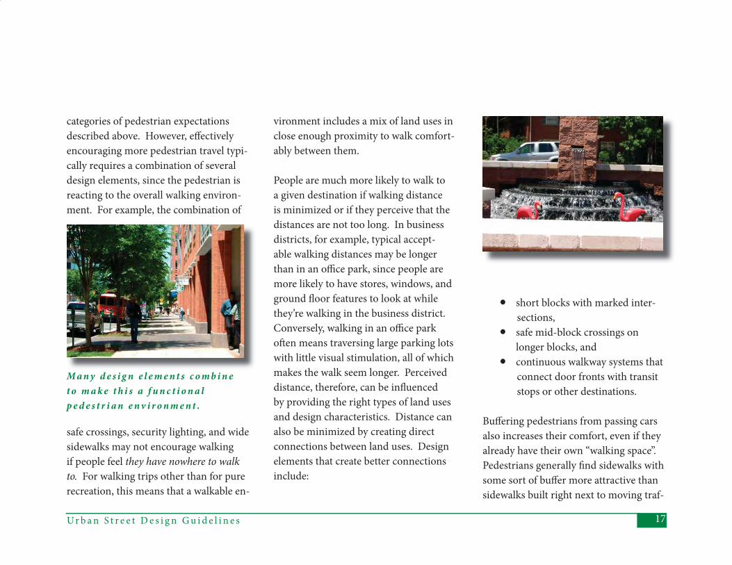
M a n y d e s i g n e l e m e n t s c o m b i n e t o m a k e t h i s a f u n c t i o n a l p e d e s t r i a n e n v i r o n m e n t .
categories of pedestrian expectations described above. However, eff ectively encouraging more pedestrian travel typi-cally requires a combination of several design elements, since the pedestrian is reacting to the overall walking environ-ment. For example, the combination of
safe crossings, security lighting, and wide sidewalks may not encourage walking if people feel they have nowhere to walk to. For walking trips other than for pure recreation, this means that a walkable en-
vironment includes a mix of land uses in close enough proximity to walk comfort-ably between them.
People are much more likely to walk to a given destination if walking distance is minimized or if they perceive that the distances are not too long. In business districts, for example, typical accept-able walking distances may be longer than in an offi ce park, since people are more likely to have stores, windows, and ground fl oor features to look at while they’re walking in the business district. Conversely, walking in an offi ce park oft en means traversing large parking lots with little visual stimulation, all of which makes the walk seem longer. Perceived distance, therefore, can be infl uenced by providing the right types of land uses and design characteristics. Distance can also be minimized by creating direct connections between land uses. Design elements that create better connections include:
• short blocks with marked inter- sections, • safe mid-block crossings on
longer blocks, and • continuous walkway systems that connect door fronts with transit stops or other destinations.
Buff ering pedestrians from passing cars also increases their comfort, even if they already have their own “walking space”. Pedestrians generally fi nd sidewalks with some sort of buff er more attractive than sidewalks built right next to moving traf-
Ur b a n S t r e e t D e s i g n G u i d e l i n e s18
fi c. Several design elements can help to create suitable buff ers between pedestri-ans and traffi c, including:
• planting strips, • bicycle lanes, • landscaping, and • on-street parking.
Th ese elements may be used alone or in combination. Th e dimensions of any one of these elements might vary, depending on how and whether it is combined with
T h e p l a n t i n g s t r i p a n d t r e e s c o m b i n e f o r b o t h v e r t i c a l a n d h o r i z o n t a l b u f f e r i n g b e t w e e n p e d e s t r i a n s a n d m o t o r v e h i c l e s .
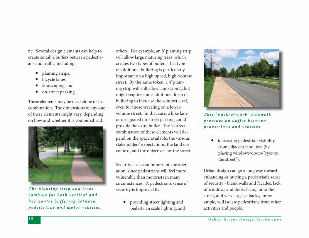
T h i s “ b a c k - o f - c u r b” s i d e w a l k p r o v i d e s n o b u f f e r b e t w e e n p e d e s t r i a n s a n d v e h i c l e s .
others. For example, an 8’ planting strip will allow large maturing trees, which creates two types of buff er. Th at type of additional buff ering is particularly important on a high-speed, high-volume street. By the same token, a 4’ plant-ing strip will still allow landscaping, but might require some additional form of buff ering to increase the comfort level, even for those traveling on a lower-volume street. In that case, a bike lane or designated on-street parking could provide the extra buff er. Th e “correct” combination of these elements will de-pend on the space available, the various stakeholders’ expectations, the land use context, and the objectives for the street.
Security is also an important consider-ation, since pedestrians will feel more vulnerable than motorists in many circumstances. A pedestrian’s sense of security is improved by:
• providing street lighting and pedestrian scale lighting, and
• increasing pedestrian visibility from adjacent land uses (by placing windows/doors/“eyes on the street”).
Urban design can go a long way toward enhancing or hurting a pedestrian’s sense of security - blank walls and facades, lack of windows and doors facing onto the street, and very large setbacks, for ex-ample, will isolate pedestrians from other activities and people.
19Ur b a n S t r e e t D e s i g n G u i d e l i n e s
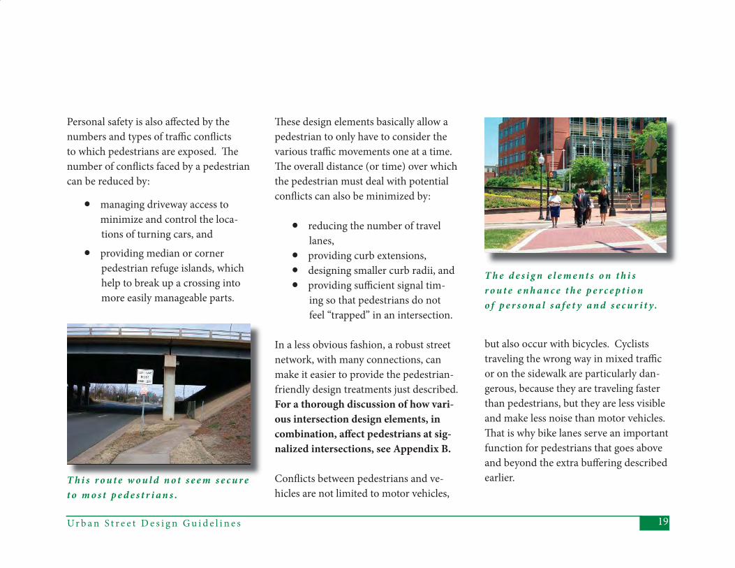
T h i s r o u t e w o u l d n o t s e e m s e c u r e t o m o s t p e d e s t r i a n s .
T h e d e s i g n e l e m e n t s o n t h i s r o u t e e n h a n c e t h e p e r c e p t i o n o f p e r s o n a l s a f e t y a n d s e c u r i t y.
Th ese design elements basically allow a pedestrian to only have to consider the various traffi c movements one at a time. Th e overall distance (or time) over which the pedestrian must deal with potential confl icts can also be minimized by:
• reducing the number of travel lanes, • providing curb extensions, • designing smaller curb radii, and • providing suffi cient signal tim- ing so that pedestrians do not feel “trapped” in an intersection.
In a less obvious fashion, a robust street network, with many connections, can make it easier to provide the pedestrian-friendly design treatments just described. For a thorough discussion of how vari-ous intersection design elements, in combination, aff ect pedestrians at sig-nalized intersections, see Appendix B.
Confl icts between pedestrians and ve-hicles are not limited to motor vehicles,
Personal safety is also aff ected by the numbers and types of traffi c confl icts to which pedestrians are exposed. Th e number of confl icts faced by a pedestrian can be reduced by:
• managing driveway access to minimize and control the loca-
tions of turning cars, and
• providing median or corner pedestrian refuge islands, which help to break up a crossing into more easily manageable parts.
but also occur with bicycles. Cyclists traveling the wrong way in mixed traffi c or on the sidewalk are particularly dan-gerous, because they are traveling faster than pedestrians, but they are less visible and make less noise than motor vehicles. Th at is why bike lanes serve an important function for pedestrians that goes above and beyond the extra buff ering described earlier.
Ur b a n S t r e e t D e s i g n G u i d e l i n e s20
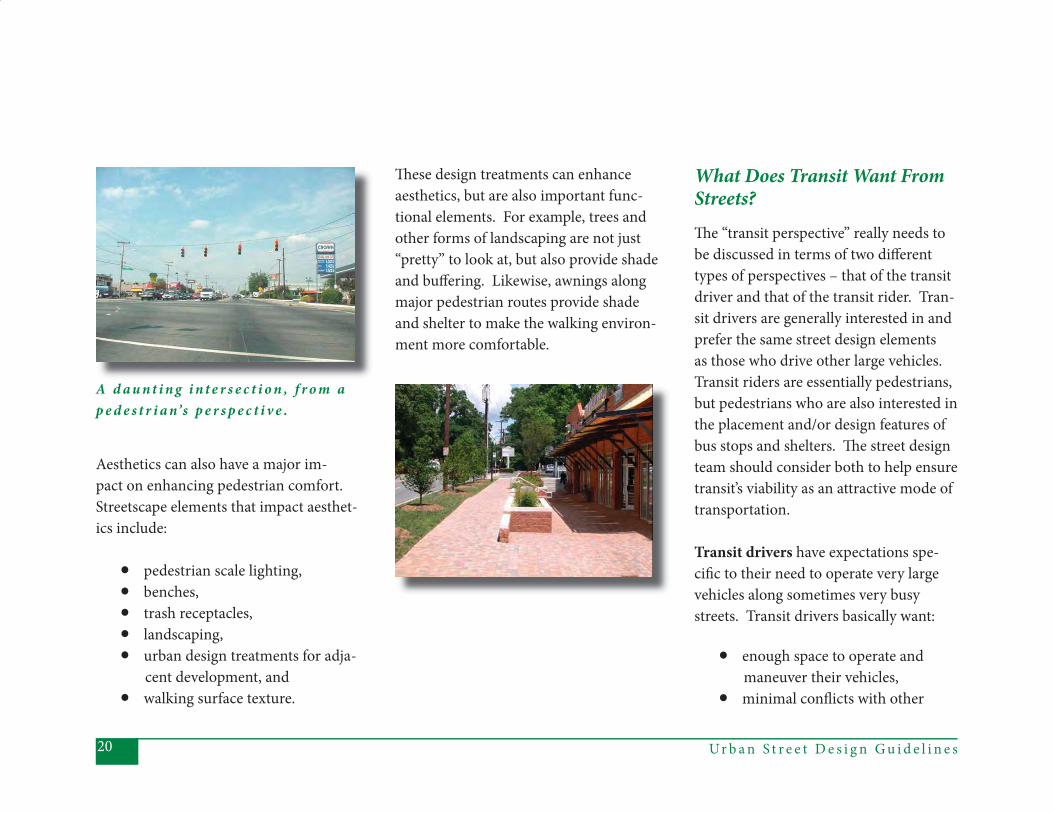
A d a u n t i n g i n t e r s e c t i o n , f r o m a p e d e s t r i a n’s p e r s p e c t i v e .
Aesthetics can also have a major im-pact on enhancing pedestrian comfort. Streetscape elements that impact aesthet-ics include:
• pedestrian scale lighting, • benches, • trash receptacles,• landscaping, • urban design treatments for adja- cent development, and • walking surface texture.
What Does Transit Want From Streets? Th e “transit perspective” really needs to be discussed in terms of two diff erent types of perspectives – that of the transit driver and that of the transit rider. Tran-sit drivers are generally interested in and prefer the same street design elements as those who drive other large vehicles. Transit riders are essentially pedestrians, but pedestrians who are also interested in the placement and/or design features of bus stops and shelters. Th e street design team should consider both to help ensure transit’s viability as an attractive mode of transportation.
Transit drivers have expectations spe-cifi c to their need to operate very large vehicles along sometimes very busy streets. Transit drivers basically want:
• enough space to operate and maneuver their vehicles,• minimal confl icts with other
Th ese design treatments can enhance aesthetics, but are also important func-tional elements. For example, trees and other forms of landscaping are not just “pretty” to look at, but also provide shade and buff ering. Likewise, awnings along major pedestrian routes provide shade and shelter to make the walking environ-ment more comfortable.

21Ur b a n S t r e e t D e s i g n G u i d e l i n e s
travelers and with features along the sides of the street, and• minimal delays, to help keep
their route operating on time.
Design elements that help provide the space for buses to operate include:
• wide travel lanes, • wide corner turning radii, • street signs, utility poles, and on-street parking located to max- imize clearance for side mirrors, and • adequate merging distances.
Transit drivers also want to reduce the potential for confl ict between transit ve-hicles and other travelers. In addition to minimizing driver fatigue, reducing such confl icts can also help minimize sched-ule delays, which harm transit opera-tions and performance. Confl icts can be minimized by:
• selecting safe locations for bus stops, and
• providing signal priority for tran- sit vehicles.
Just as delay will aff ect transit operations, so can the ability to provide more route coverage and travel effi ciency. Cover-age and effi ciency are impacted by the extent of the street network. Short blocks providing multiple route options can increase pedestrians’ access to transit as well as transit’s access to more land uses (and potential riders).
Transit riders have the same types of in-terests as do other pedestrians, with some additional, specifi c expectations. Transit riders also want:
• accessible bus stops, • easy connections, and • personal comfort and security while waiting for the bus.
Generally speaking, accessibility comes from having well-located transit stops on a well-connected network. Th e spacing
of bus stops and their locations rela-tive to pedestrian-oriented or clustered land uses will aff ect peoples’ ability or willingness to use transit. Transit stops should be located so that walk distances are not excessive. In addition, those land uses located near transit stops should be designed with entrances and sidewalks connecting buildings directly to the stop or to the nearest public sidewalk.
Accessibility is further improved by having a dense, well-connected network for pedestrians. Such a network can be achieved by including short blocks on the street network or bike-pedestrian
Ur b a n S t r e e t D e s i g n G u i d e l i n e s22
Closely related to their need for acces-sibility, transit riders also want to be able to change modes as easily as possible. Intermodal accessibility is provided through an extensive pedestrian sidewalk network with easy street crossings (de-
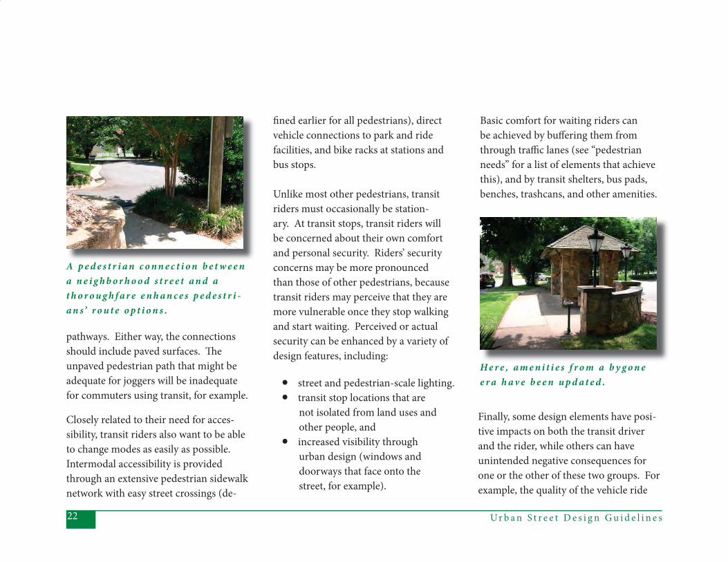
A p e d e s t r i a n c o n n e c t i o n b e t w e e n a n e i g h b o r h o o d s t r e e t a n d a t h o r o u g h f a r e e n h a n c e s p e d e s t r i -a n s’ r o u t e o p t i o n s .
fi ned earlier for all pedestrians), direct vehicle connections to park and ride facilities, and bike racks at stations and bus stops.
Unlike most other pedestrians, transit riders must occasionally be station-ary. At transit stops, transit riders will be concerned about their own comfort and personal security. Riders’ security concerns may be more pronounced than those of other pedestrians, because transit riders may perceive that they are more vulnerable once they stop walking and start waiting. Perceived or actual security can be enhanced by a variety of design features, including:
• street and pedestrian-scale lighting.• transit stop locations that are not isolated from land uses and other people, and • increased visibility through urban design (windows and doorways that face onto the street, for example).
Basic comfort for waiting riders can be achieved by buff ering them from through traffi c lanes (see “pedestrian needs” for a list of elements that achieve this), and by transit shelters, bus pads, benches, trashcans, and other amenities.
Finally, some design elements have posi-tive impacts on both the transit driver and the rider, while others can have unintended negative consequences for one or the other of these two groups. For example, the quality of the vehicle ride
pathways. Either way, the connections should include paved surfaces. Th e unpaved pedestrian path that might be adequate for joggers will be inadequate for commuters using transit, for example.
H e r e , a m e n i t i e s f r o m a b y g o n e e r a h a v e b e e n u p d a t e d .
23Ur b a n S t r e e t D e s i g n G u i d e l i n e s
aff ects both drivers and riders. Th e ride quality can be improved by minimizing vertical grade variations along curb lanes at cross-streets and drainage grate areas, and by providing smooth, well-main-tained street surfaces. Conversely, the wider lanes and curb radii that provide more maneuvering space for the tran-sit vehicles can create less comfortable streets for transit riders. Bus pullouts may reduce delays to motorists who would otherwise have to wait behind the
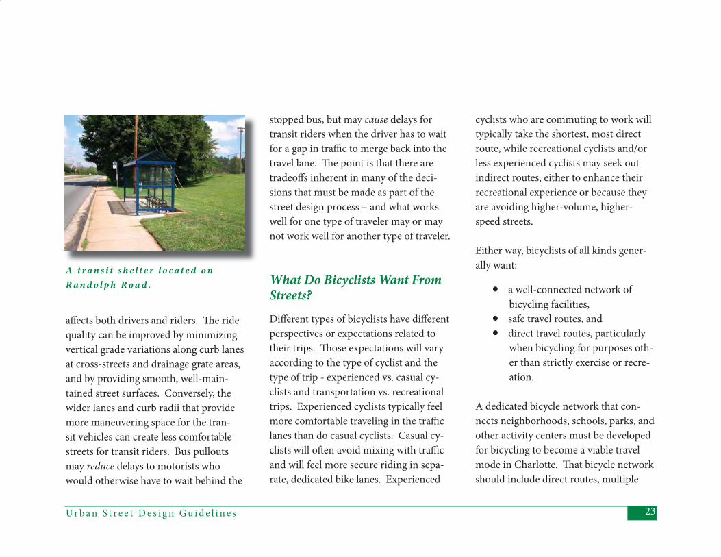
A t r a n s i t s h e l t e r l o c a t e d o n R a n d o l p h R o a d .
stopped bus, but may cause delays for transit riders when the driver has to wait for a gap in traffi c to merge back into the travel lane. Th e point is that there are tradeoff s inherent in many of the deci-sions that must be made as part of the street design process – and what works well for one type of traveler may or may not work well for another type of traveler.
What Do Bicyclists Want From Streets? Diff erent types of bicyclists have diff erent perspectives or expectations related to their trips. Th ose expectations will vary according to the type of cyclist and the type of trip - experienced vs. casual cy-clists and transportation vs. recreational trips. Experienced cyclists typically feel more comfortable traveling in the traffi c lanes than do casual cyclists. Casual cy-clists will oft en avoid mixing with traffi c and will feel more secure riding in sepa-rate, dedicated bike lanes. Experienced
cyclists who are commuting to work will typically take the shortest, most direct route, while recreational cyclists and/or less experienced cyclists may seek out indirect routes, either to enhance their recreational experience or because they are avoiding higher-volume, higher-speed streets.
Either way, bicyclists of all kinds gener-ally want:
• a well-connected network of bicycling facilities,• safe travel routes, and• direct travel routes, particularly when bicycling for purposes oth- er than strictly exercise or recre- ation.
A dedicated bicycle network that con-nects neighborhoods, schools, parks, and other activity centers must be developed for bicycling to become a viable travel mode in Charlotte. Th at bicycle network should include direct routes, multiple
Ur b a n S t r e e t D e s i g n G u i d e l i n e s24
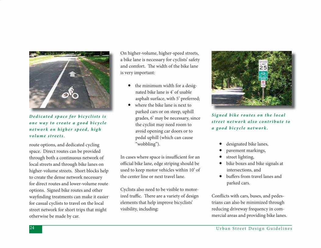
D e d i c a t e d s p a c e f o r b i c y c l i s t s i s o n e w a y t o c r e a t e a g o o d b i c y c l e n e t w o r k o n h i g h e r s p e e d , h i g h v o l u m e s t r e e t s .
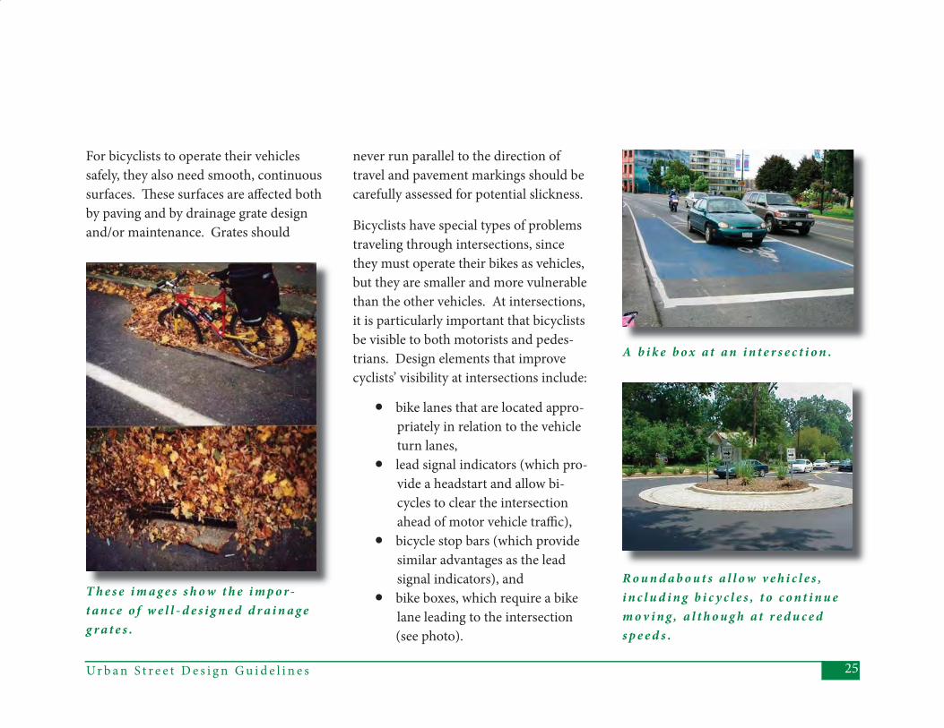
S i g n e d b i k e r o u t e s o n t h e l o c a l s t r e e t n e t w o r k a l s o c o n t r i b u t e t o a g o o d b i c y c l e n e t w o r k .
route options, and dedicated cycling space. Direct routes can be provided through both a continuous network of local streets and through bike lanes on higher-volume streets. Short blocks help to create the dense network necessary for direct routes and lower-volume route options. Signed bike routes and other wayfi nding treatments can make it easier for casual cyclists to travel on the local street network for short trips that might otherwise be made by car.
On higher-volume, higher-speed streets, a bike lane is necessary for cyclists’ safety and comfort. Th e width of the bike lane is very important:
• the minimum width for a desig- nated bike lane is 4’ of usable asphalt surface, with 5’ preferred; • where the bike lane is next to parked cars or on steep, uphill grades, 6’ may be necessary, since the cyclist may need room to avoid opening car doors or to pedal uphill (which can cause “wobbling”).
In cases where space is insuffi cient for an offi cial bike lane, edge striping should be used to keep motor vehicles within 10’ of the center line or next travel lane.
Cyclists also need to be visible to motor-ized traffi c. Th ere are a variety of design elements that help improve bicyclists’ visibility, including:
• designated bike lanes, • pavement markings, • street lighting, • bike boxes and bike signals at intersections, and • buff ers from travel lanes and parked cars.
Confl icts with cars, buses, and pedes-trians can also be minimized through reducing driveway frequency in com-mercial areas and providing bike lanes.
25Ur b a n S t r e e t D e s i g n G u i d e l i n e s
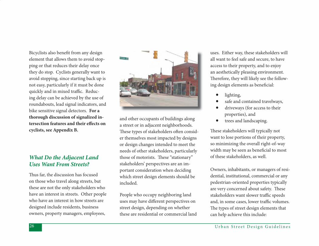
For bicyclists to operate their vehicles safely, they also need smooth, continuous surfaces. Th ese surfaces are aff ected both by paving and by drainage grate design and/or maintenance. Grates should
T h e s e i m a g e s s h o w t h e i m p o r -t a n c e o f w e l l - d e s i g n e d d r a i n a g e g r a t e s .
Bicyclists have special types of problems traveling through intersections, since they must operate their bikes as vehicles, but they are smaller and more vulnerable than the other vehicles. At intersections, it is particularly important that bicyclists be visible to both motorists and pedes-trians. Design elements that improve cyclists’ visibility at intersections include:
• bike lanes that are located appro- priately in relation to the vehicle turn lanes, • lead signal indicators (which pro- vide a headstart and allow bi- cycles to clear the intersection ahead of motor vehicle traffi c), • bicycle stop bars (which provide similar advantages as the lead signal indicators), and • bike boxes, which require a bike lane leading to the intersection
(see photo).
never run parallel to the direction of travel and pavement markings should be carefully assessed for potential slickness.
A b i k e b o x a t a n i n t e r s e c t i o n .
R o u n d a b o u t s a l l o w v e h i c l e s , i n c l u d i n g b i c y c l e s , t o c o n t i n u e m o v i n g , a l t h o u g h a t r e d u c e d s p e e d s .
Ur b a n S t r e e t D e s i g n G u i d e l i n e s26
Bicyclists also benefi t from any design element that allows them to avoid stop-ping or that reduces their delay once they do stop. Cyclists generally want to avoid stopping, since starting back up is not easy, particularly if it must be done quickly and in mixed traffi c. Reduc-ing delay can be achieved by the use of roundabouts, lead signal indicators, and bike sensitive signal detectors. For a thorough discussion of signalized in-tersection features and their eff ects on cyclists, see Appendix B.
What Do the Adjacent Land Uses Want From Streets?Th us far, the discussion has focused on those who travel along streets, but these are not the only stakeholders who have an interest in streets. Other people who have an interest in how streets are designed include residents, business owners, property managers, employees,
uses. Either way, these stakeholders will all want to feel safe and secure, to have access to their property, and to enjoy an aesthetically pleasing environment. Th erefore, they will likely see the follow-ing design elements as benefi cial:
• lighting, • safe and contained travelways, • driveways (for access to their
properties), and • trees and landscaping.
Th ese stakeholders will typically not want to lose portions of their property, so minimizing the overall right-of-way width may be seen as benefi cial to most of these stakeholders, as well.
Owners, inhabitants, or managers of resi-dential, institutional, commercial or any pedestrian-oriented properties typically are very concerned about safety. Th ese stakeholders want slower traffi c speeds and, in some cases, lower traffi c volumes. Th e types of street design elements that can help achieve this include:
People who occupy neighboring land uses may have diff erent perspectives on street design, depending on whether these are residential or commercial land
and other occupants of buildings along a street or in adjacent neighborhoods. Th ese types of stakeholders oft en consid-er themselves most impacted by designs or design changes intended to meet the needs of other stakeholders, particularly those of motorists. Th ese “stationary” stakeholders’ perspectives are an im-portant consideration when deciding which street design elements should be included.
27Ur b a n S t r e e t D e s i g n G u i d e l i n e s
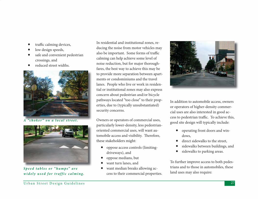
A “c h o k e r ” o n a l o c a l s t r e e t .
S p e e d t a b l e s o r “ h u m p s” a r e w i d e l y u s e d f o r t r a f f i c c a l m i n g .
• traffi c calming devices, • low design speeds, • safe and convenient pedestrian
crossings, and • reduced street widths.
In residential and institutional zones, re-ducing the noise from motor vehicles may also be important. Some forms of traffi c calming can help achieve some level of noise reduction, but for major thorough-fares, the best way to achieve this may be to provide more separation between apart-ments or condominiums and the travel lanes. People who live or work in residen-tial or institutional zones may also express concern about pedestrian and/or bicycle pathways located “too close” to their prop-erties, due to (typically unsubstantiated) security concerns.
Owners or operators of commercial uses, particularly lower-density, less pedestrian-oriented commercial uses, will want au-tomobile access and visibility. Th erefore, these stakeholders might:
• oppose access controls (limiting-driveways), and
• oppose medians, but • want turn lanes, and • want median breaks allowing ac-
cess to their commercial properties.
In addition to automobile access, owners or operators of higher-density commer-cial uses are also interested in good ac-cess to pedestrian traffi c. To achieve this, good site design will typically include:
• operating front doors and win- dows,
• direct sidewalks to the street, • sidewalks between buildings, and • sidewalks to parking areas.
To further improve access to both pedes-trians and to those in automobiles, these land uses may also require:
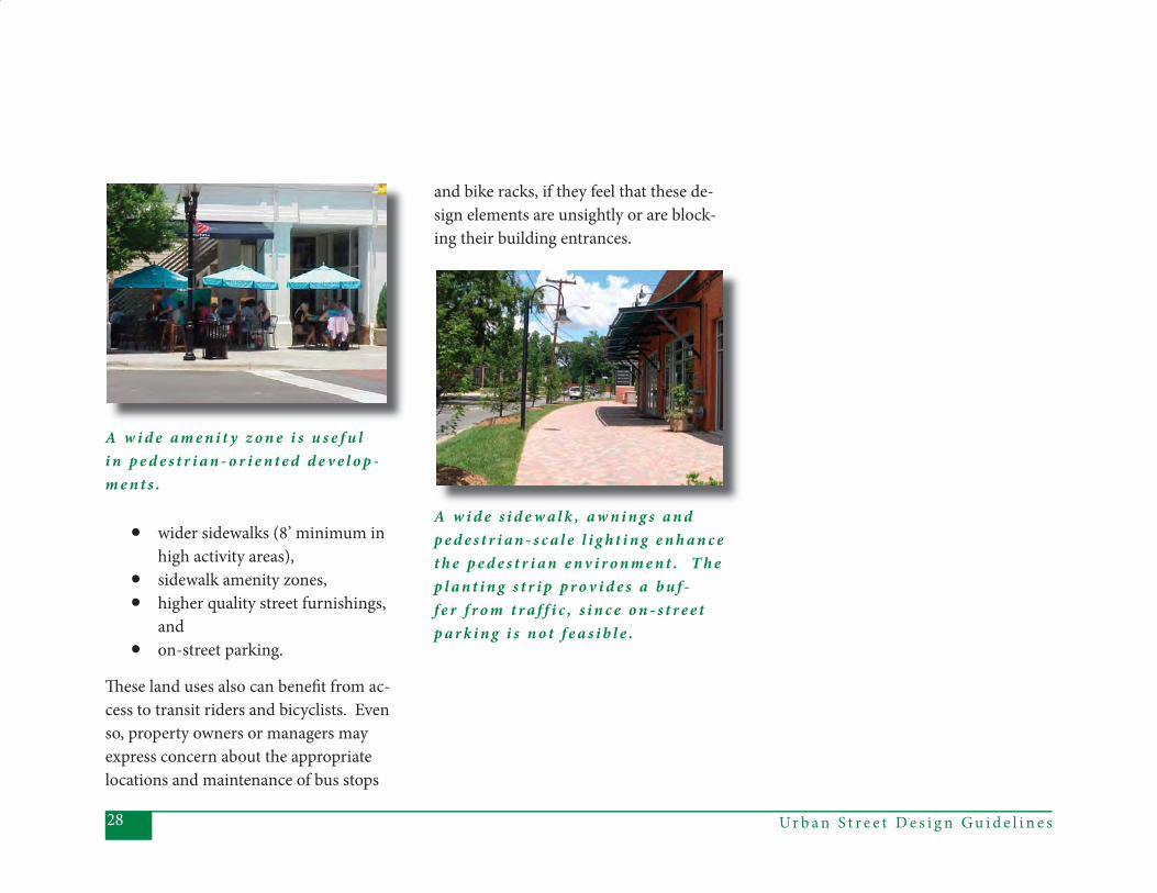
Ur b a n S t r e e t D e s i g n G u i d e l i n e s28
• wider sidewalks (8’ minimum in high activity areas),
• sidewalk amenity zones, • higher quality street furnishings,
and • on-street parking.
Th ese land uses also can benefi t from ac-cess to transit riders and bicyclists. Even so, property owners or managers may express concern about the appropriate locations and maintenance of bus stops
A w i d e a m e n i t y z o n e i s u s e f u l i n p e d e s t r i a n - o r i e n t e d d e v e l o p -m e n t s .
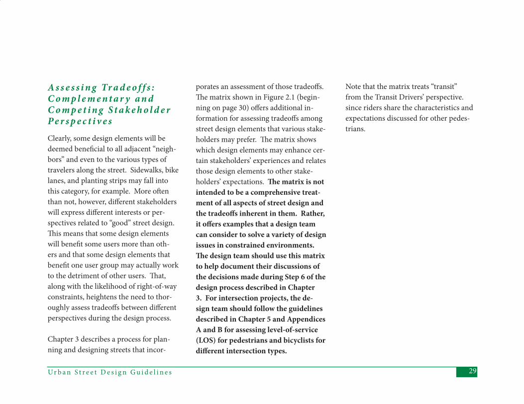
and bike racks, if they feel that these de-sign elements are unsightly or are block-ing their building entrances.
A w i d e s i d e w a l k , a w n i n g s a n d p e d e s t r i a n - s c a l e l i g h t i n g e n h a n c e t h e p e d e s t r i a n e n v i r o n m e n t . T h e p l a n t i n g s t r i p p r o v i d e s a b u f -f e r f r o m t r a f f i c , s i n c e o n - s t r e e t p a r k i n g i s n o t f e a s i b l e .
29Ur b a n S t r e e t D e s i g n G u i d e l i n e s
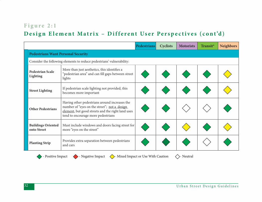
A s s e s s i n g Tr a d e o f f s : C o m p l e m e n t a r y a n d C o m p e t i n g S t a k e h o l d e r P e r s p e c t i v e sClearly, some design elements will be deemed benefi cial to all adjacent “neigh-bors” and even to the various types of travelers along the street. Sidewalks, bike lanes, and planting strips may fall into this category, for example. More oft en than not, however, diff erent stakeholders will express diff erent interests or per-spectives related to “good” street design. Th is means that some design elements will benefi t some users more than oth-ers and that some design elements that benefi t one user group may actually work to the detriment of other users. Th at, along with the likelihood of right-of-way constraints, heightens the need to thor-oughly assess tradeoff s between diff erent perspectives during the design process.
Chapter 3 describes a process for plan-ning and designing streets that incor-
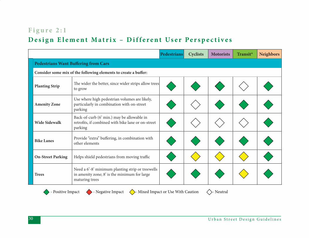
porates an assessment of those tradeoff s. Th e matrix shown in Figure 2.1 (begin-ning on page 30) off ers additional in-formation for assessing tradeoff s among street design elements that various stake-holders may prefer. Th e matrix shows which design elements may enhance cer-tain stakeholders’ experiences and relates those design elements to other stake-holders’ expectations. Th e matrix is not intended to be a comprehensive treat-ment of all aspects of street design and the tradeoff s inherent in them. Rather, it off ers examples that a design team can consider to solve a variety of design issues in constrained environments. Th e design team should use this matrix to help document their discussions of the decisions made during Step 6 of the design process described in Chapter 3. For intersection projects, the de-sign team should follow the guidelines described in Chapter 5 and Appendices A and B for assessing level-of-service (LOS) for pedestrians and bicyclists for diff erent intersection types.
Note that the matrix treats “transit” from the Transit Drivers’ perspective. since riders share the characteristics and expectations discussed for other pedes-trians.
Ur b a n S t r e e t D e s i g n G u i d e l i n e s30
Pedestrians Cyclists Motorists Transit* Neighbors
Pedestrians Want Buff ering from Cars
Consider some mix of the following elements to create a buff er:
Planting Strip Th e wider the better, since wider strips allow trees to grow
Amenity ZoneUse where high pedestrian volumes are likely, particularly in combination with on-street parking
Wide SidewalkBack-of-curb (6’ min.) may be allowable in retrofi ts, if combined with bike lane or on-street parking
Bike Lanes Provide “extra” buff ering, in combination with other elements
On-Street Parking Helps shield pedestrians from moving traffi c
TreesNeed a 6’-8’ minimum planting strip or treewells in amenity zone; 8’ is the minimum for large maturing trees
- Positive Impact - Negative Impact - Mixed Impact or Use With Caution - Neutral
F i g u r e 2 : 1 D e s i g n E l e m e n t M a t r i x – D i f f e r e n t Us e r Pe r s p e c t i v e s
31Ur b a n S t r e e t D e s i g n G u i d e l i n e s
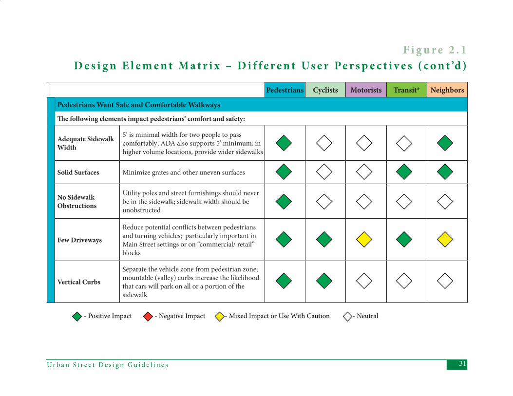
Pedestrians Cyclists Motorists Transit* Neighbors
Pedestrians Want Safe and Comfortable Walkways
Th e following elements impact pedestrians’ comfort and safety:
Adequate Sidewalk Width
5’ is minimal width for two people to pass comfortably; ADA also supports 5’ minimum; in higher volume locations, provide wider sidewalks
Solid Surfaces Minimize grates and other uneven surfaces
No Sidewalk Obstructions
Utility poles and street furnishings should never be in the sidewalk; sidewalk width should be unobstructed
Few Driveways
Reduce potential confl icts between pedestrians and turning vehicles; particularly important in Main Street settings or on “commercial/ retail” blocks
Vertical Curbs
Separate the vehicle zone from pedestrian zone; mountable (valley) curbs increase the likelihood that cars will park on all or a portion of the sidewalk
- Positive Impact - Negative Impact - Mixed Impact or Use With Caution - Neutral
F i g u r e 2 . 1 D e s i g n E l e m e n t M a t r i x – D i f f e r e n t Us e r Pe r s p e c t i v e s ( c o n t ’d )
Ur b a n S t r e e t D e s i g n G u i d e l i n e s32
Pedestrians Cyclists Motorists Transit* Neighbors
Pedestrians Want Personal Security
Consider the following elements to reduce pedestrians’ vulnerability:
Pedestrian Scale Lighting
More than just aesthetics, this identifi es a “pedestrian area” and can fi ll gaps between street lights
Street Lighting If pedestrian scale lighting not provided, this becomes more important
Other Pedestrians
Having other pedestrians around increases the number of “eyes on the street”; not a design element, but good streets and the right land uses tend to encourage more pedestrians
Buildings Oriented onto Street
Must include windows and doors facing street for more “eyes on the street”
Planting Strip Provides extra separation between pedestrians and cars
- Positive Impact - Negative Impact - Mixed Impact or Use With Caution - Neutral
F i g u r e 2 : 1 D e s i g n E l e m e n t M a t r i x – D i f f e r e n t Us e r Pe r s p e c t i v e s ( c o n t ’d )
33Ur b a n S t r e e t D e s i g n G u i d e l i n e s
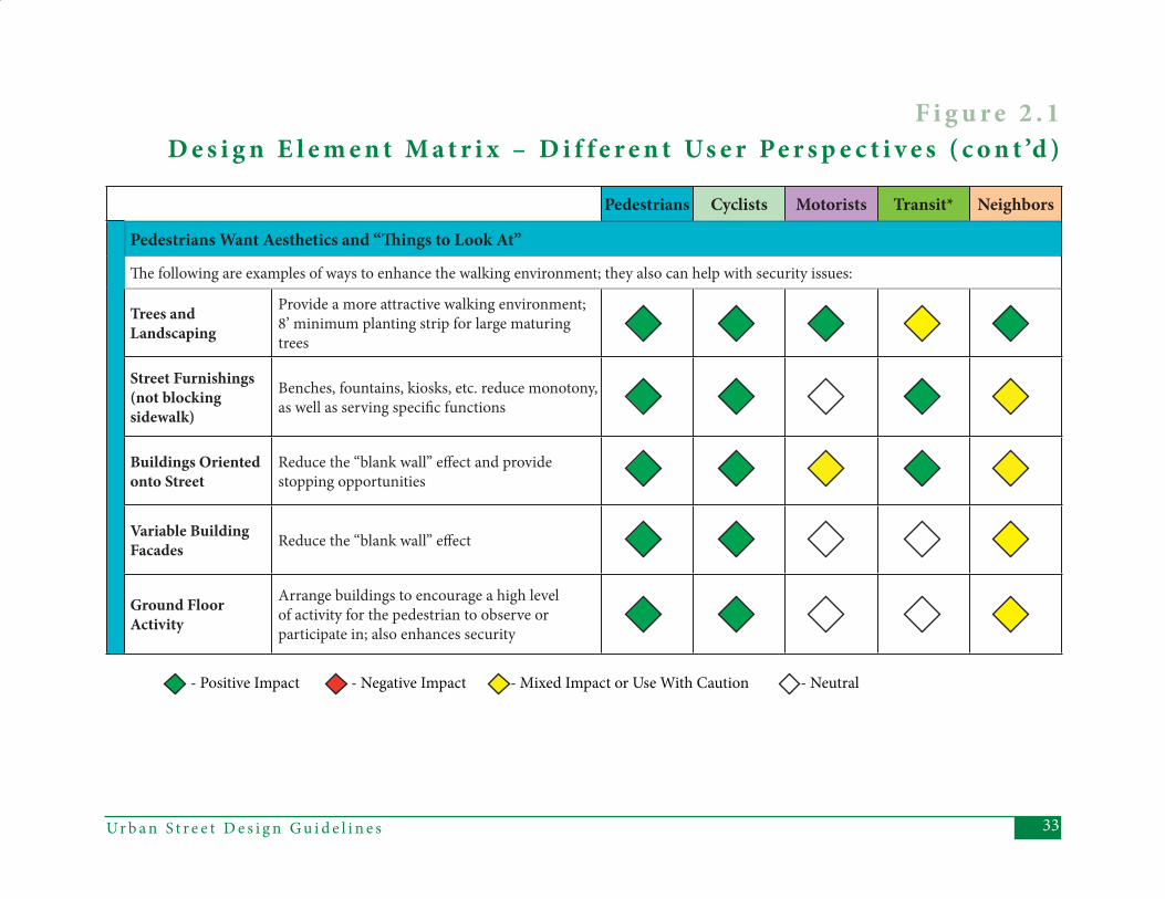
Pedestrians Cyclists Motorists Transit* Neighbors
Pedestrians Want Aesthetics and “Th ings to Look At”
Th e following are examples of ways to enhance the walking environment; they also can help with security issues:
Trees and Landscaping
Provide a more attractive walking environment; 8’ minimum planting strip for large maturing trees
Street Furnishings (not blocking sidewalk)
Benches, fountains, kiosks, etc. reduce monotony, as well as serving specifi c functions
Buildings Oriented onto Street
Reduce the “blank wall” eff ect and provide stopping opportunities
Variable Building Facades Reduce the “blank wall” eff ect
Ground Floor Activity
Arrange buildings to encourage a high level of activity for the pedestrian to observe or participate in; also enhances security
- Positive Impact - Negative Impact - Mixed Impact or Use With Caution - Neutral
F i g u r e 2 . 1 D e s i g n E l e m e n t M a t r i x – D i f f e r e n t Us e r Pe r s p e c t i v e s ( c o n t ’d )
Ur b a n S t r e e t D e s i g n G u i d e l i n e s34
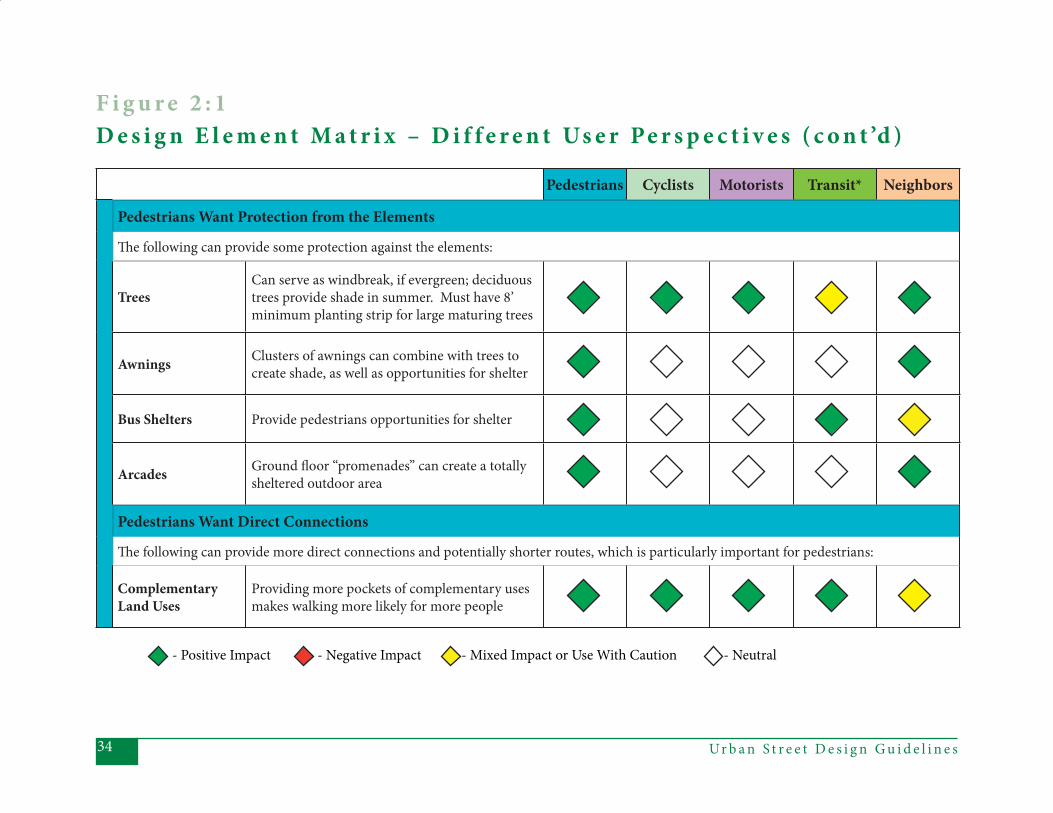
Pedestrians Cyclists Motorists Transit* Neighbors
Pedestrians Want Protection from the Elements
Th e following can provide some protection against the elements:
TreesCan serve as windbreak, if evergreen; deciduous trees provide shade in summer. Must have 8’ minimum planting strip for large maturing trees
Awnings Clusters of awnings can combine with trees to create shade, as well as opportunities for shelter
Bus Shelters Provide pedestrians opportunities for shelter
Arcades Ground fl oor “promenades” can create a totally sheltered outdoor area
Pedestrians Want Direct Connections
Th e following can provide more direct connections and potentially shorter routes, which is particularly important for pedestrians:
Complementary Land Uses
Providing more pockets of complementary uses makes walking more likely for more people
- Positive Impact - Negative Impact - Mixed Impact or Use With Caution - Neutral
F i g u r e 2 : 1 D e s i g n E l e m e n t M a t r i x – D i f f e r e n t Us e r Pe r s p e c t i v e s ( c o n t ’d )
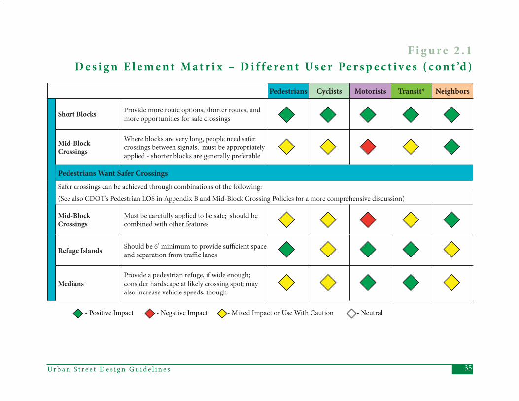
35Ur b a n S t r e e t D e s i g n G u i d e l i n e s
Pedestrians Cyclists Motorists Transit* Neighbors
Short Blocks Provide more route options, shorter routes, and more opportunities for safe crossings
Mid-Block Crossings
Where blocks are very long, people need safer crossings between signals; must be appropriately applied - shorter blocks are generally preferable
Pedestrians Want Safer CrossingsSafer crossings can be achieved through combinations of the following:(See also CDOT’s Pedestrian LOS in Appendix B and Mid-Block Crossing Policies for a more comprehensive discussion)
Mid-Block Crossings
Must be carefully applied to be safe; should be combined with other features
Refuge Islands Should be 6’ minimum to provide suffi cient space and separation from traffi c lanes
MediansProvide a pedestrian refuge, if wide enough; consider hardscape at likely crossing spot; may also increase vehicle speeds, though
- Positive Impact - Negative Impact - Mixed Impact or Use With Caution - Neutral
F i g u r e 2 . 1 D e s i g n E l e m e n t M a t r i x – D i f f e r e n t Us e r Pe r s p e c t i v e s ( c o n t ’d )
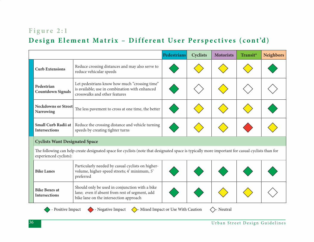
Ur b a n S t r e e t D e s i g n G u i d e l i n e s36
Pedestrians Cyclists Motorists Transit* Neighbors
Curb Extensions Reduce crossing distances and may also serve to reduce vehicular speeds
Pedestrian Countdown Signals
Let pedestrians know how much “crossing time” is available; use in combination with enhanced crosswalks and other features
Neckdowns or Street Narrowing Th e less pavement to cross at one time, the better
Small Curb Radii at Intersections
Reduce the crossing distance and vehicle turning speeds by creating tighter turns
Cyclists Want Designated Space
Th e following can help create designated space for cyclists (note that designated space is typically more important for casual cyclists than for experienced cyclists):
Bike LanesParticularly needed by casual cyclists on higher-volume, higher-speed streets; 4’ minimum, 5’ preferred
Bike Boxes at Intersections
Should only be used in conjunction with a bike lane; even if absent from rest of segment, add bike lane on the intersection approach
- Positive Impact - Negative Impact - Mixed Impact or Use With Caution - Neutral
F i g u r e 2 : 1 D e s i g n E l e m e n t M a t r i x – D i f f e r e n t Us e r Pe r s p e c t i v e s ( c o n t ’d )
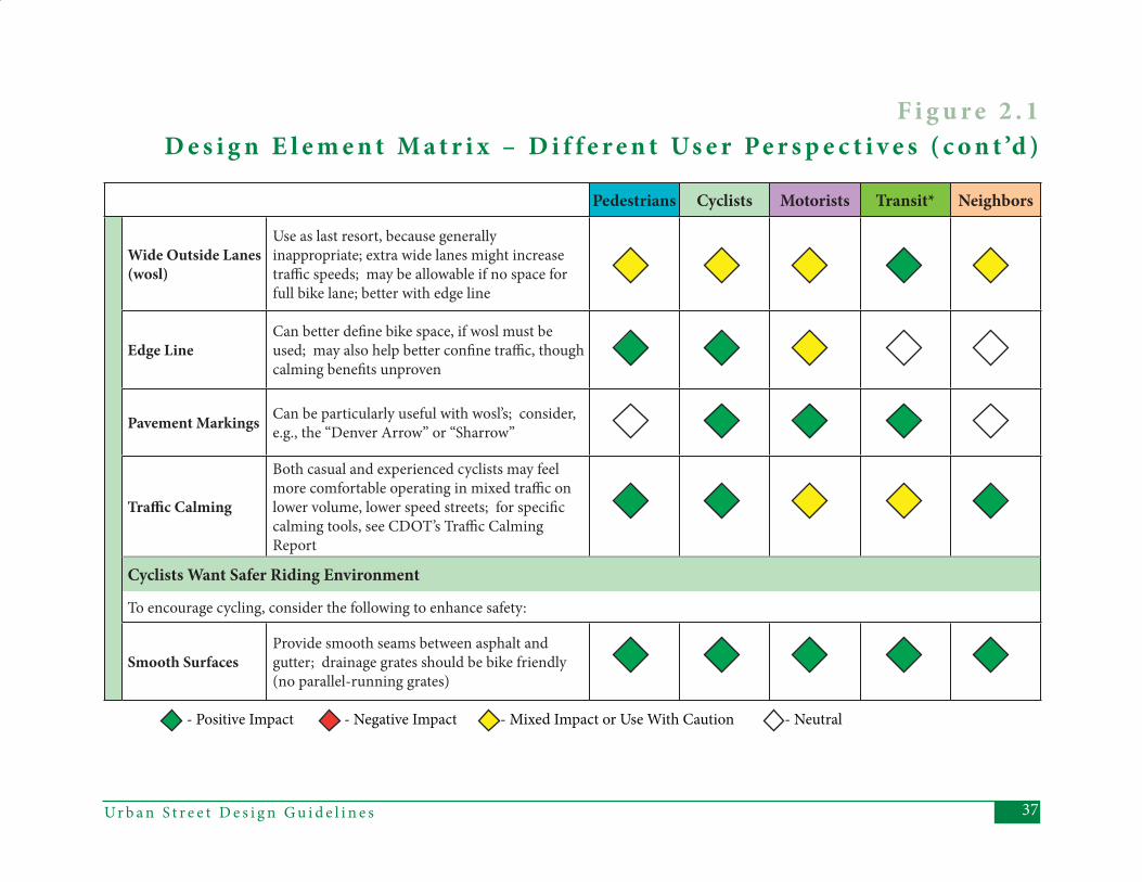
37Ur b a n S t r e e t D e s i g n G u i d e l i n e s
Pedestrians Cyclists Motorists Transit* Neighbors
Wide Outside Lanes (wosl)
Use as last resort, because generally inappropriate; extra wide lanes might increase traffi c speeds; may be allowable if no space for full bike lane; better with edge line
Edge LineCan better defi ne bike space, if wosl must be used; may also help better confi ne traffi c, though calming benefi ts unproven
Pavement Markings Can be particularly useful with wosl’s; consider, e.g., the “Denver Arrow” or “Sharrow”
Traffi c Calming
Both casual and experienced cyclists may feel more comfortable operating in mixed traffi c on lower volume, lower speed streets; for specifi c calming tools, see CDOT’s Traffi c Calming Report
Cyclists Want Safer Riding Environment
To encourage cycling, consider the following to enhance safety:
Smooth SurfacesProvide smooth seams between asphalt and gutter; drainage grates should be bike friendly (no parallel-running grates)
- Positive Impact - Negative Impact - Mixed Impact or Use With Caution - Neutral
F i g u r e 2 . 1 D e s i g n E l e m e n t M a t r i x – D i f f e r e n t Us e r Pe r s p e c t i v e s ( c o n t ’d )

Ur b a n S t r e e t D e s i g n G u i d e l i n e s38
Pedestrians Cyclists Motorists Transit* Neighbors
Street Lighting Bike lights more useful for visibility to drivers than for lighting the way
No On-Street Parking
Opening car doors create potential hazard; however, wide bikes lanes alleviate this hazard
Separation from On-Street Parking
If on-street parking is used, either parking lane or bike lane should be wider than minimum
No Front-In Angle Parking
Seriously limits cyclists’ visibility to drivers; however, reverse angle parking alleviates this hazard
Reverse Angle Parking
Puts cyclist in drivers’ sightline, but also requires more space and buff ering than parallel parking
- Positive Impact - Negative Impact - Mixed Impact or Use With Caution - Neutral
F i g u r e 2 : 1 D e s i g n E l e m e n t M a t r i x – D i f f e r e n t Us e r Pe r s p e c t i v e s ( c o n t ’d )
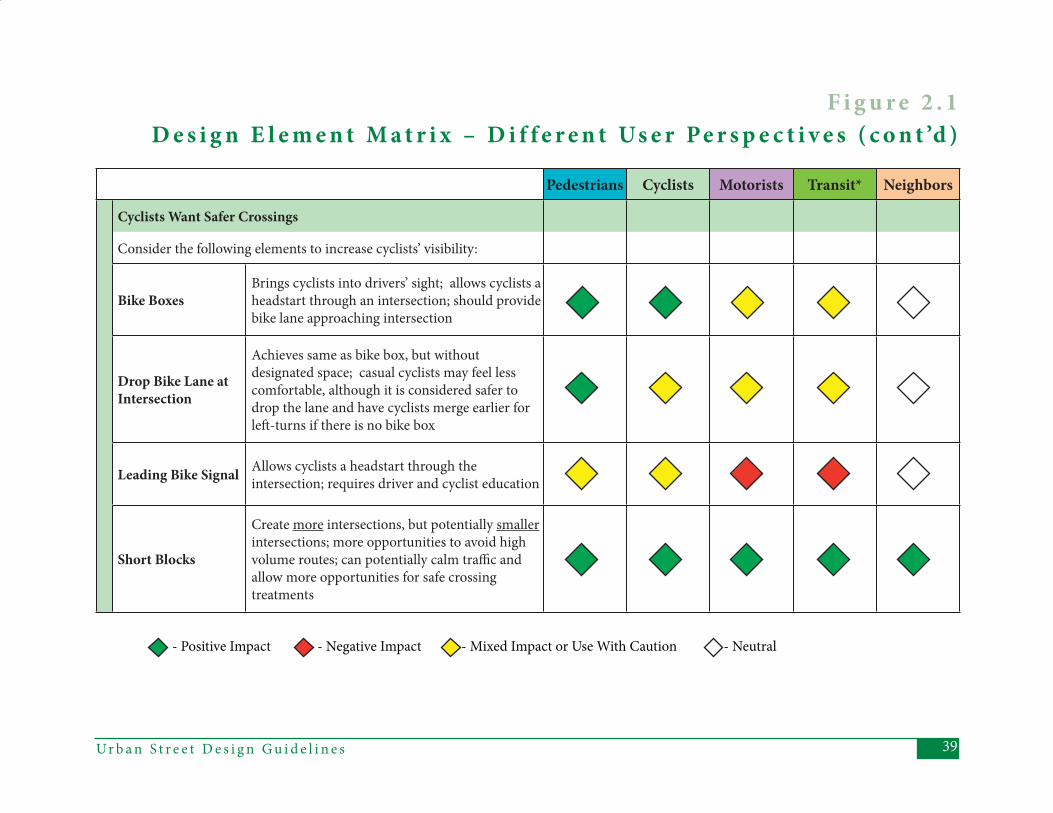
39Ur b a n S t r e e t D e s i g n G u i d e l i n e s
Pedestrians Cyclists Motorists Transit* Neighbors
Cyclists Want Safer Crossings
Consider the following elements to increase cyclists’ visibility:
Bike BoxesBrings cyclists into drivers’ sight; allows cyclists a headstart through an intersection; should provide bike lane approaching intersection
Drop Bike Lane at Intersection
Achieves same as bike box, but without designated space; casual cyclists may feel less comfortable, although it is considered safer to drop the lane and have cyclists merge earlier for left -turns if there is no bike box
Leading Bike Signal Allows cyclists a headstart through the intersection; requires driver and cyclist education
Short Blocks
Create more intersections, but potentially smaller intersections; more opportunities to avoid high volume routes; can potentially calm traffi c and allow more opportunities for safe crossing treatments
- Positive Impact - Negative Impact - Mixed Impact or Use With Caution - Neutral
F i g u r e 2 . 1 D e s i g n E l e m e n t M a t r i x – D i f f e r e n t Us e r Pe r s p e c t i v e s ( c o n t ’d )
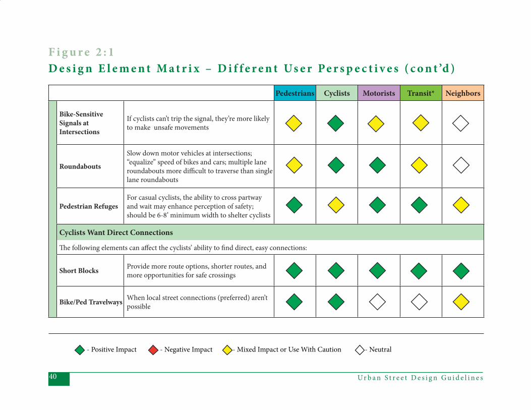
Ur b a n S t r e e t D e s i g n G u i d e l i n e s40
Pedestrians Cyclists Motorists Transit* Neighbors
Bike-Sensitive Signals at Intersections
If cyclists can’t trip the signal, they’re more likely to make unsafe movements
Roundabouts
Slow down motor vehicles at intersections; “equalize” speed of bikes and cars; multiple lane roundabouts more diffi cult to traverse than single lane roundabouts
Pedestrian RefugesFor casual cyclists, the ability to cross partway and wait may enhance perception of safety; should be 6-8’ minimum width to shelter cyclists
Cyclists Want Direct Connections
Th e following elements can aff ect the cyclists’ ability to fi nd direct, easy connections:
Short Blocks Provide more route options, shorter routes, and more opportunities for safe crossings
Bike/Ped Travelways When local street connections (preferred) aren’t possible
- Positive Impact - Negative Impact - Mixed Impact or Use With Caution - Neutral
F i g u r e 2 : 1 D e s i g n E l e m e n t M a t r i x – D i f f e r e n t Us e r Pe r s p e c t i v e s ( c o n t ’d )
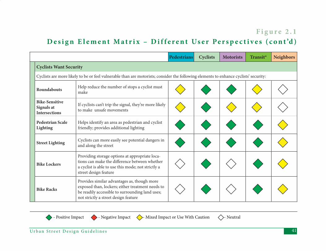
41Ur b a n S t r e e t D e s i g n G u i d e l i n e s
Pedestrians Cyclists Motorists Transit* Neighbors
Cyclists Want Security
Cyclists are more likely to be or feel vulnerable than are motorists; consider the following elements to enhance cyclists’ security:
Roundabouts Help reduce the number of stops a cyclist must make
Bike-Sensitive Signals at Intersections
If cyclists can’t trip the signal, they’re more likely to make unsafe movements
Pedestrian Scale Lighting
Helps identify an area as pedestrian and cyclist friendly; provides additional lighting
Street Lighting Cyclists can more easily see potential dangers in and along the street
Bike Lockers
Providing storage options at appropriate loca-tions can make the diff erence between whether a cyclist is able to use this mode; not strictly a street design feature
Bike Racks
Provides similar advantages as, though more exposed than, lockers; either treatment needs to be readily accessible to surrounding land uses; not strictly a street design feature
- Positive Impact - Negative Impact - Mixed Impact or Use With Caution - Neutral
F i g u r e 2 . 1 D e s i g n E l e m e n t M a t r i x – D i f f e r e n t Us e r Pe r s p e c t i v e s ( c o n t ’d )
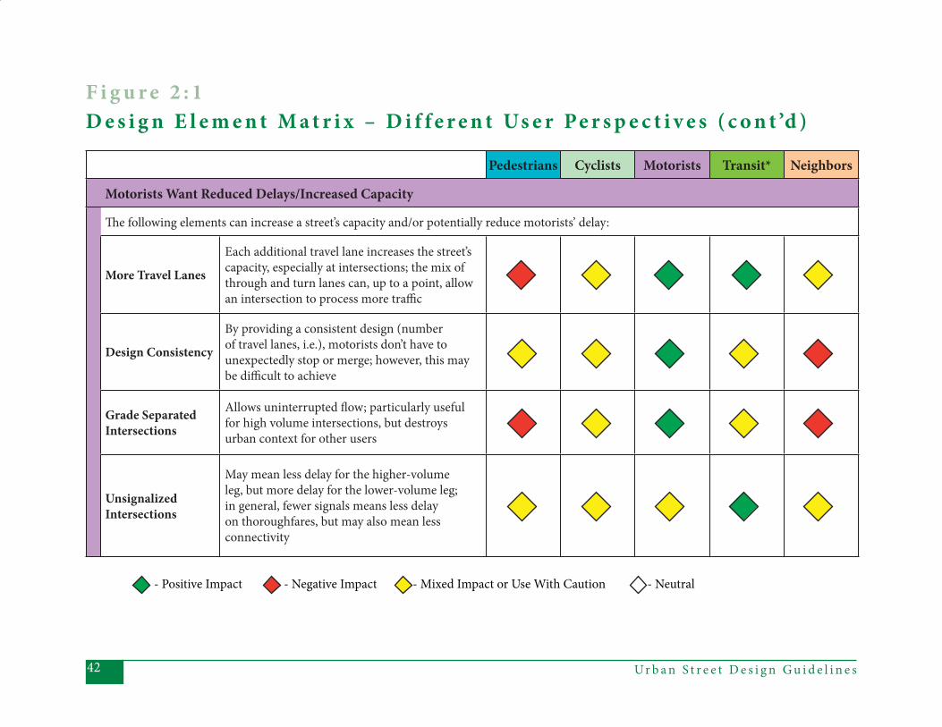
Ur b a n S t r e e t D e s i g n G u i d e l i n e s42
Pedestrians Cyclists Motorists Transit* Neighbors
Motorists Want Reduced Delays/Increased Capacity
Th e following elements can increase a street’s capacity and/or potentially reduce motorists’ delay:
More Travel Lanes
Each additional travel lane increases the street’s capacity, especially at intersections; the mix of through and turn lanes can, up to a point, allow an intersection to process more traffi c
Design Consistency
By providing a consistent design (number of travel lanes, i.e.), motorists don’t have to unexpectedly stop or merge; however, this may be diffi cult to achieve
Grade Separated Intersections
Allows uninterrupted fl ow; particularly useful for high volume intersections, but destroys urban context for other users
Unsignalized Intersections
May mean less delay for the higher-volume leg, but more delay for the lower-volume leg; in general, fewer signals means less delay on thoroughfares, but may also mean less connectivity
- Positive Impact - Negative Impact - Mixed Impact or Use With Caution - Neutral
F i g u r e 2 : 1 D e s i g n E l e m e n t M a t r i x – D i f f e r e n t Us e r Pe r s p e c t i v e s ( c o n t ’d )
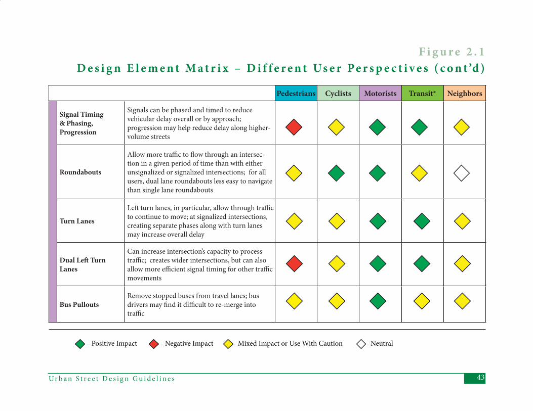
43Ur b a n S t r e e t D e s i g n G u i d e l i n e s
Pedestrians Cyclists Motorists Transit* Neighbors
Signal Timing & Phasing, Progression
Signals can be phased and timed to reduce vehicular delay overall or by approach; progression may help reduce delay along higher-volume streets
Roundabouts
Allow more traffi c to fl ow through an intersec-tion in a given period of time than with either unsignalized or signalized intersections; for all users, dual lane roundabouts less easy to navigate than single lane roundabouts
Turn Lanes
Left turn lanes, in particular, allow through traffi c to continue to move; at signalized intersections, creating separate phases along with turn lanes may increase overall delay
Dual Left Turn Lanes
Can increase intersection’s capacity to process traffi c; creates wider intersections, but can also allow more effi cient signal timing for other traffi c movements
Bus PulloutsRemove stopped buses from travel lanes; bus drivers may fi nd it diffi cult to re-merge into traffi c
- Positive Impact - Negative Impact - Mixed Impact or Use With Caution - Neutral
F i g u r e 2 . 1 D e s i g n E l e m e n t M a t r i x – D i f f e r e n t Us e r Pe r s p e c t i v e s ( c o n t ’d )
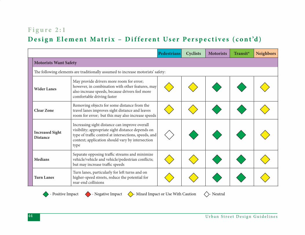
Ur b a n S t r e e t D e s i g n G u i d e l i n e s44
Pedestrians Cyclists Motorists Transit* Neighbors
Motorists Want Safety
Th e following elements are traditionally assumed to increase motorists’ safety:
Wider Lanes
May provide drivers more room for error; however, in combination with other features, may also increase speeds, because drivers feel more comfortable driving faster
Clear ZoneRemoving objects for some distance from the travel lanes improves sight distance and leaves room for error; but this may also increase speeds
Increased Sight Distance
Increasing sight distance can improve overall visibility; appropriate sight distance depends on type of traffi c control at intersections, speeds, and context; application should vary by intersection type
MediansSeparate opposing traffi c streams and minimize vehicle/vehicle and vehicle/pedestrian confl icts; but may increase traffi c speeds
Turn LanesTurn lanes, particularly for left turns and on higher-speed streets, reduce the potential for rear-end collisions
- Positive Impact - Negative Impact - Mixed Impact or Use With Caution - Neutral
F i g u r e 2 : 1 D e s i g n E l e m e n t M a t r i x – D i f f e r e n t Us e r Pe r s p e c t i v e s ( c o n t ’d )
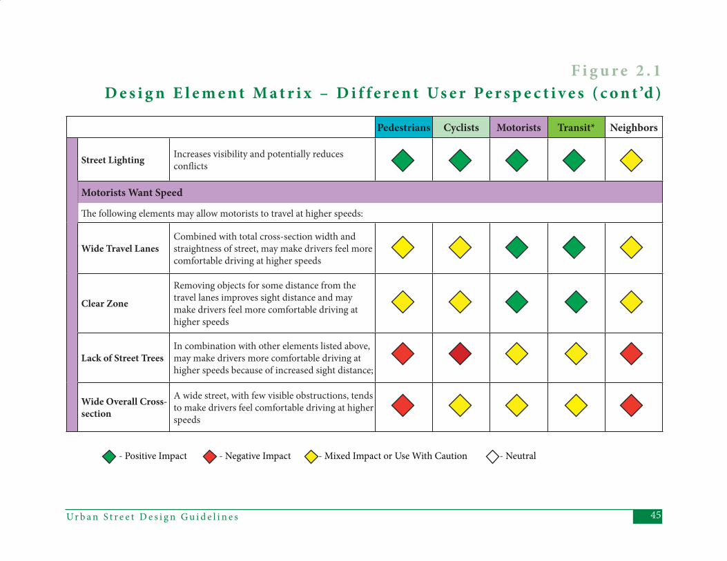
45Ur b a n S t r e e t D e s i g n G u i d e l i n e s
Pedestrians Cyclists Motorists Transit* Neighbors
Street Lighting Increases visibility and potentially reduces confl icts
Motorists Want Speed
Th e following elements may allow motorists to travel at higher speeds:
Wide Travel LanesCombined with total cross-section width and straightness of street, may make drivers feel more comfortable driving at higher speeds
Clear Zone
Removing objects for some distance from the travel lanes improves sight distance and may make drivers feel more comfortable driving at higher speeds
Lack of Street TreesIn combination with other elements listed above, may make drivers more comfortable driving at higher speeds because of increased sight distance;
Wide Overall Cross-section
A wide street, with few visible obstructions, tends to make drivers feel comfortable driving at higher speeds
- Positive Impact - Negative Impact - Mixed Impact or Use With Caution - Neutral
F i g u r e 2 . 1 D e s i g n E l e m e n t M a t r i x – D i f f e r e n t Us e r Pe r s p e c t i v e s ( c o n t ’d )
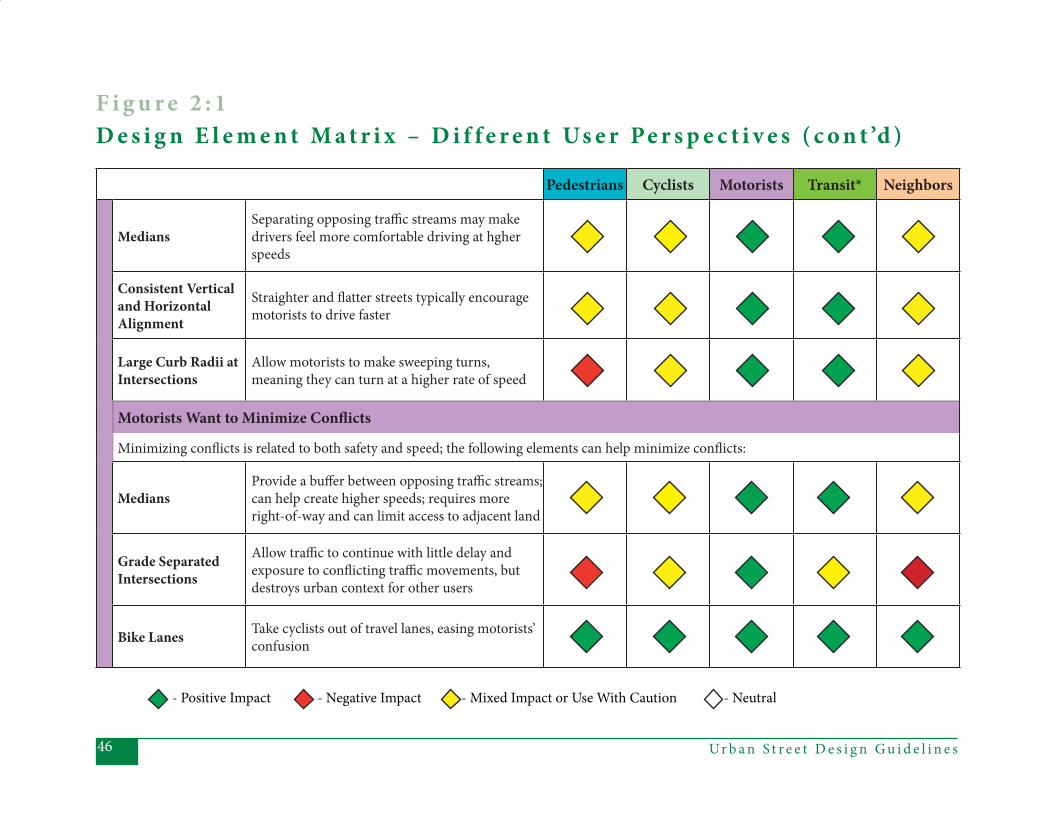
Ur b a n S t r e e t D e s i g n G u i d e l i n e s46
Pedestrians Cyclists Motorists Transit* Neighbors
MediansSeparating opposing traffi c streams may make drivers feel more comfortable driving at hgher speeds
Consistent Vertical and Horizontal Alignment
Straighter and fl atter streets typically encourage motorists to drive faster
Large Curb Radii at Intersections
Allow motorists to make sweeping turns, meaning they can turn at a higher rate of speed
Motorists Want to Minimize Confl icts
Minimizing confl icts is related to both safety and speed; the following elements can help minimize confl icts:
MediansProvide a buff er between opposing traffi c streams; can help create higher speeds; requires more right-of-way and can limit access to adjacent land
Grade Separated Intersections
Allow traffi c to continue with little delay and exposure to confl icting traffi c movements, but destroys urban context for other users
Bike Lanes Take cyclists out of travel lanes, easing motorists’ confusion
- Positive Impact - Negative Impact - Mixed Impact or Use With Caution - Neutral
F i g u r e 2 : 1 D e s i g n E l e m e n t M a t r i x – D i f f e r e n t Us e r Pe r s p e c t i v e s ( c o n t ’d )
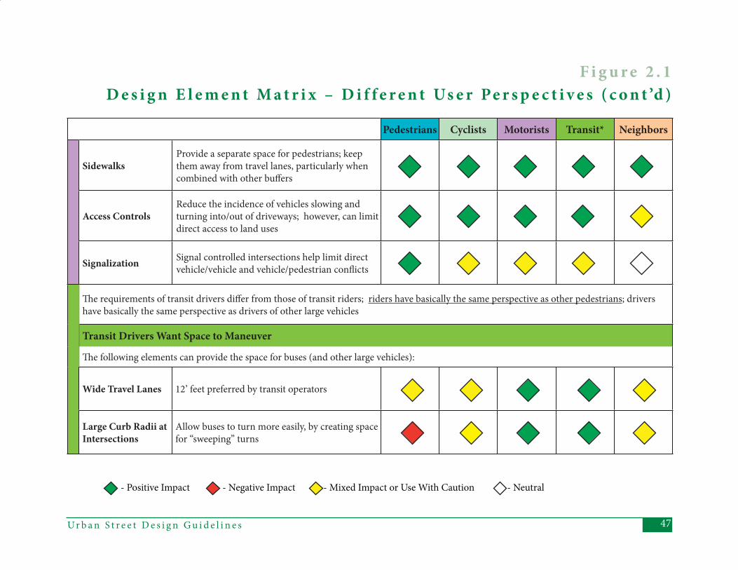
47Ur b a n S t r e e t D e s i g n G u i d e l i n e s
Pedestrians Cyclists Motorists Transit* Neighbors
SidewalksProvide a separate space for pedestrians; keep them away from travel lanes, particularly when combined with other buff ers
Access ControlsReduce the incidence of vehicles slowing and turning into/out of driveways; however, can limit direct access to land uses
Signalization Signal controlled intersections help limit direct vehicle/vehicle and vehicle/pedestrian confl icts
Th e requirements of transit drivers diff er from those of transit riders; riders have basically the same perspective as other pedestrians; drivers have basically the same perspective as drivers of other large vehicles
Transit Drivers Want Space to Maneuver
Th e following elements can provide the space for buses (and other large vehicles):
Wide Travel Lanes 12’ feet preferred by transit operators
Large Curb Radii at Intersections
Allow buses to turn more easily, by creating space for “sweeping” turns
F i g u r e 2 . 1 D e s i g n E l e m e n t M a t r i x – D i f f e r e n t Us e r Pe r s p e c t i v e s ( c o n t ’d )
- Positive Impact - Negative Impact - Mixed Impact or Use With Caution - Neutral
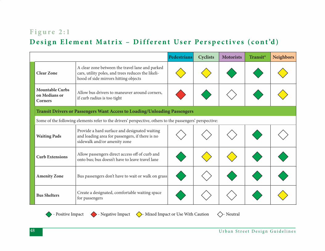
Ur b a n S t r e e t D e s i g n G u i d e l i n e s48
Pedestrians Cyclists Motorists Transit* Neighbors
Clear ZoneA clear zone between the travel lane and parked cars, utility poles, and trees reduces the likeli-hood of side mirrors hitting objects
Mountable Curbs on Medians or Corners
Allow bus drivers to maneuver around corners, if curb radius is too tight
Transit Drivers or Passengers Want Access to Loading/Unloading Passengers
Some of the following elements refer to the drivers’ perspective, others to the passengers’ perspective:
Waiting PadsProvide a hard surface and designated waiting and loading area for passengers, if there is no sidewalk and/or amenity zone
Curb Extensions Allow passengers direct access off of curb and onto bus; bus doesn’t have to leave travel lane
Amenity Zone Bus passengers don’t have to wait or walk on grass
Bus Shelters Create a designated, comfortable waiting space for passengers
- Positive Impact - Negative Impact - Mixed Impact or Use With Caution - Neutral
F i g u r e 2 : 1 D e s i g n E l e m e n t M a t r i x – D i f f e r e n t Us e r Pe r s p e c t i v e s ( c o n t ’d )
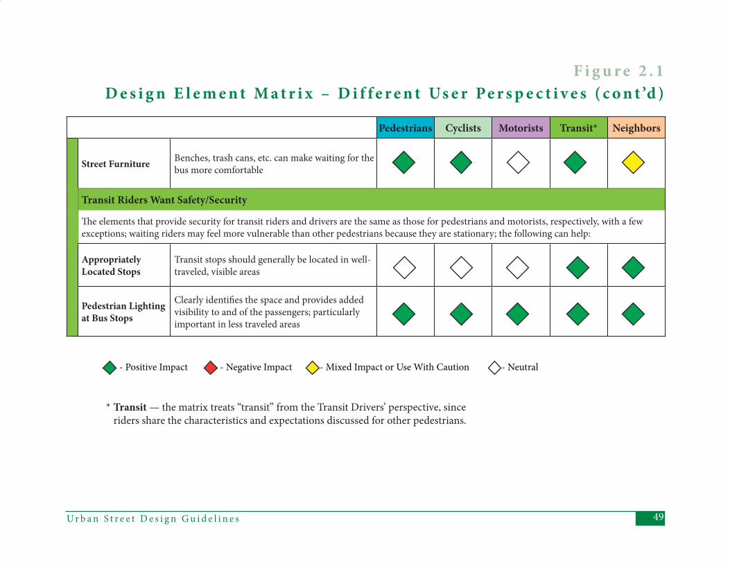
49Ur b a n S t r e e t D e s i g n G u i d e l i n e s
Pedestrians Cyclists Motorists Transit* Neighbors
Street Furniture Benches, trash cans, etc. can make waiting for the bus more comfortable
Transit Riders Want Safety/Security
Th e elements that provide security for transit riders and drivers are the same as those for pedestrians and motorists, respectively, with a few exceptions; waiting riders may feel more vulnerable than other pedestrians because they are stationary; the following can help:
Appropriately Located Stops
Transit stops should generally be located in well-traveled, visible areas
Pedestrian Lighting at Bus Stops
Clearly identifi es the space and provides added visibility to and of the passengers; particularly important in less traveled areas
- Positive Impact - Negative Impact - Mixed Impact or Use With Caution - Neutral
F i g u r e 2 . 1 D e s i g n E l e m e n t M a t r i x – D i f f e r e n t Us e r Pe r s p e c t i v e s ( c o n t ’d )
* Transit — the matrix treats “transit” from the Transit Drivers’ perspective, since riders share the characteristics and expectations discussed for other pedestrians.

Ur b a n S t r e e t D e s i g n G u i d e l i n e s50
51Ur b a n S t r e e t D e s i g n G u i d e l i n e s
3 . A P P LY I N G T H E G U I D E L I N E S
T he previous chapter explained that various stakeholders have diff er-
ent expectations of what makes streets “good” or even “great”. To appropriately apply the Urban Street Design Guide-lines (USDG), the plan/design team must assess the expectations of a variety of stakeholders in order for streets to best refl ect their contexts and intended func-tions. Th is assessment is also intended to ensure that the resulting streets are “complete” streets – streets that provide for the safety and comfort of all users to the best extent possible.
Th e purpose of this chapter is to explain how the perspectives of all stakeholders interested in or aff ected by existing or future streets will be incorporated into a new process for planning and designing streets in Charlotte’s Sphere of Infl uence. Th e new process described in this chap-ter consolidates traditional city planning, urban design, and transportation plan-ning activities into a sequence of fact-fi nding and decision-making steps.
Th e application of the new process for planning and designing streets is intended to support the creation of “more streets for more people.” Th is overriding goal of the USDG will require achieving the following changes:
1. Ensuring that the perspectives of all stakeholders interested or aff ected by streets are seriously considered during the planning and design process for existing or future streets;
2. Defi ning a clear sequence of activities to be undertaken by staff , consultants and stakeholders;
3. Remembering that this will be a process that is much more geared toward what we want to happen in the future than just accepting what happened in the past or exists now;
4. Verifying that the inevitable tradeoff s aff ecting objectives, benefi ts, costs, and impacts are
well documented so that the recommendations made by staff , consultants or stakeholders are based on understanding the direct eff ects on specifi c modes of travel and/or land use intentions; and
5. Always striving to create not only more streets, but also more complete streets that are good for all modes of travel, and even some great streets that are remarkable because of the very eff ective and favorable ways that the adjacent land uses and transportation functions of those streets support each other.
Th e process described in this chapter provides a great deal of fl exibility to those involved in the decision-making process, to ensure that the resulting streets are appropriately based on the existing and proposed land use and transportation contexts. Th is fl exibility
51Ur b a n S t r e e t D e s i g n G u i d e l i n e s
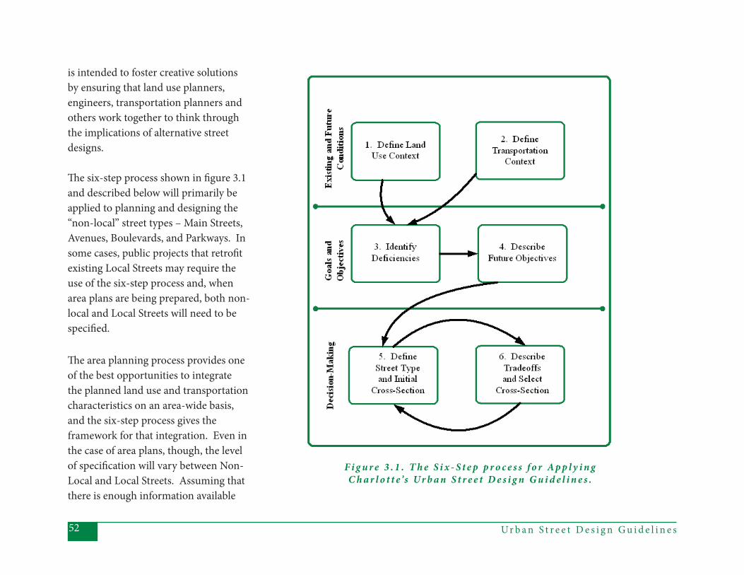
Ur b a n S t r e e t D e s i g n G u i d e l i n e s52
is intended to foster creative solutions by ensuring that land use planners, engineers, transportation planners and others work together to think through the implications of alternative street designs.
Th e six-step process shown in fi gure 3.1 and described below will primarily be applied to planning and designing the “non-local” street types – Main Streets, Avenues, Boulevards, and Parkways. In some cases, public projects that retrofi t existing Local Streets may require the use of the six-step process and, when area plans are being prepared, both non-local and Local Streets will need to be specifi ed. Th e area planning process provides one of the best opportunities to integrate the planned land use and transportation characteristics on an area-wide basis, and the six-step process gives the framework for that integration. Even in the case of area plans, though, the level of specifi cation will vary between Non-Local and Local Streets. Assuming that there is enough information available
F i g u r e 3 . 1 . T h e S i x - S t e p p r o c e s s f o r A p p l y i n g C h a r l o t t e ’s Ur b a n S t r e e t D e s i g n G u i d e l i n e s .
53Ur b a n S t r e e t D e s i g n G u i d e l i n e s
about future land use context and future transportation context, the planning team would specify the actual cross-sections for all non-local streets in the area plan. For the Local Streets, the planning team would specify the spacing of the emerging Local Street network, and the specifi c cross-sections would be applied based on the adjacent land uses, as the streets are constructed.
For the most part, however, new Local Streets will be built through the land development process and the major design decision will be to select the appropriate pre-defi ned cross-section, as described in Chapter 4,rather than to apply the six-step process. Conversely, retrofi tting a non-local street with limited right-of-way through an existing neighborhood will be more complicated and require more of a tradeoff analysis.
A p p l y i n g t h e G u i d e l i n e s :S i x S t e p sTh e remainder of this chapter defi nes a six-step process for developing the most appropriate design for streets in a
variety of contexts. Th e following three assumptions are built into the six-step process:
1. Th e process will involve a variety of stakeholders. Th e number of stakeholders and discussions will vary, depending on the magnitude and consequences of the street(s) to be designed.
2. Th e resulting street will be as “complete” a street as possible, in order to meet the multi-modal objectives defi ned in the Transportation Action Plan.
3. Th e steps in the decision-making process will be well-documented. Th e documentation will clearly describe the major tradeoff s made among competing design elements, how those were discussed and weighed against each other, and the preliminary and fi nal outcomes. Th orough documentation will ensure that all stakeholders’ perspectives are adequately considered in the fi nal design.
Figure 3.1 (previous page) shows the assessment steps to be included in applying the USDG. Each of the six steps is defi ned in more detail in the remainder of the chapter. It is important to note that the steps described below can be applied either to a single street or to a collection of streets in an area (such as when an area plan is being developed). In either case, the fi rst four steps should take an area-wide approach to gathering and assessing the information required for each step, since even individual street segments do not exist or function in isolation from the surrounding street network and land uses.
Step 1: Defi ne the Existing and Future Land Use and Urban Design ContextTh e classifi cation and ultimate design of any street should refl ect both the existing and expected future land use contexts. Th ese existing and future contexts should be considered from the broadest, area-wide perspective down to the details of the immediately adjacent land uses. A street is likely to be classifi ed and/or
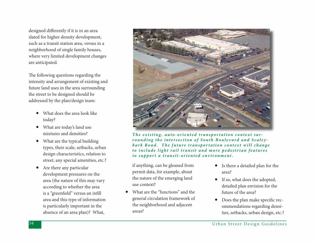
Ur b a n S t r e e t D e s i g n G u i d e l i n e s54
designed diff erently if it is in an area slated for higher density development, such as a transit station area, versus in a neighborhood of single family houses, where very limited development changes are anticipated.
Th e following questions regarding the intensity and arrangement of existing and future land uses in the area surrounding the street to be designed should be addressed by the plan/design team:
• What does the area look like today?
• What are today’s land use mixtures and densities?
• What are the typical building types, their scale, setbacks, urban design characteristics, relation to street, any special amenities, etc.?
• Are there any particular development pressures on the area (the nature of this may vary according to whether the area is a “greenfi eld” versus an infi ll area and this type of information is particularly important in the absence of an area plan)? What,
if anything, can be gleaned from permit data, for example, about the nature of the emerging land use context?
• What are the “functions” and the general circulation framework of the neighborhood and adjacent areas?
• Is there a detailed plan for the area?
• If so, what does the adopted, detailed plan envision for the future of the area?
• Does the plan make specifi c rec-ommendations regarding densi-ties, setbacks, urban design, etc.?
T h e e x i s t i n g , a u t o - o r i e n t e d t r a n s p o r t a t i o n c o n t e x t s u r -r o u n d i n g t h e i n t e r s e c t i o n o f S o u t h B o u l e v a r d a n d S c a l e y -b a r k R o a d . T h e f u t u r e t r a n s p o r t a t i o n c o n t e x t w i l l c h a n g e t o i n c l u d e l i g h t r a i l t r a n s i t a n d m o r e p e d e s t r i a n f e a t u r e s t o s u p p o r t a t r a n s i t - o r i e n t e d e n v i r o n m e n t .
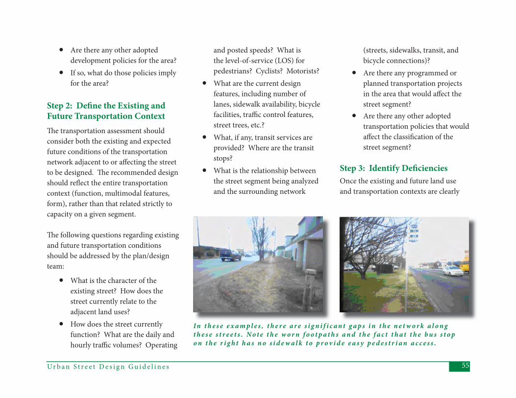
55Ur b a n S t r e e t D e s i g n G u i d e l i n e s
• Are there any other adopted development policies for the area?
• If so, what do those policies imply for the area?
Step 2: Defi ne the Existing and Future Transportation ContextTh e transportation assessment should consider both the existing and expected future conditions of the transportation network adjacent to or aff ecting the street to be designed. Th e recommended design should refl ect the entire transportation context (function, multimodal features, form), rather than that related strictly to capacity on a given segment.
Th e following questions regarding existing and future transportation conditions should be addressed by the plan/design team:
• What is the character of the existing street? How does the street currently relate to the adjacent land uses?
• How does the street currently function? What are the daily and hourly traffi c volumes? Operating
and posted speeds? What is the level-of-service (LOS) for pedestrians? Cyclists? Motorists?
• What are the current design features, including number of lanes, sidewalk availability, bicycle facilities, traffi c control features, street trees, etc.?
• What, if any, transit services are provided? Where are the transit stops?
• What is the relationship between the street segment being analyzed and the surrounding network
(streets, sidewalks, transit, and bicycle connections)?
• Are there any programmed or planned transportation projects in the area that would aff ect the street segment?
• Are there any other adopted transportation policies that would aff ect the classifi cation of the street segment?
Step 3: Identify Defi cienciesOnce the existing and future land use and transportation contexts are clearly
In t h e s e e x a m p l e s , t h e r e a r e s i g n i f i c a n t g a p s i n t h e n e t w o r k a l o n g t h e s e s t r e e t s . N o t e t h e w o r n f o o t p a t h s a n d t h e f a c t t h a t t h e b u s s t o p o n t h e r i g h t h a s n o s i d e w a l k t o p r o v i d e e a s y p e d e s t r i a n a c c e s s .

Ur b a n S t r e e t D e s i g n G u i d e l i n e s56
defi ned and understood from an area-wide perspective, the plan/design team should be able to identify and describe any defi ciencies that could/should be addressed by the new or modifi ed street. Th is step should consider all modes and the relationship between the transportation and the land use contexts.
From the information provided in the fi rst two steps, “defi ciencies” might include, but are not limited to:
L e f t a n d Ab o v e : T h e s t r e e t n e t -w o r k s u r r o u n d i n g t h i s s e g m e n t o f R e a R o a d , i n s o u t h C h a r l o t t e , i s v e r y d i s c o n n e c t e d , w h i c h h a s r a m i f i c a t i o n s f o r m o t o r i s t s , b i c y c l i s t s , a n d p e d e s t r i a n s .
• Gaps in the bicycle or pedestrian
network near or along the street segment;
• Gaps in the bicycle or pedestrian network in the area (which may increase the need for facilities on the segment, because of the lack of alternative routes);
• Insuffi cient pedestrian or bicycle facilities (in poor repair, poorly lighted, or not well buff ered from traffi c, e.g.);
• Gaps in the overall street network (this includes the amount of connectivity in the area, as well as any obvious capacity issues on other segments in the area);
• Inconsistencies between the amount or type of transit service provided along the street segment and the types of facilities and/or land uses adjacent to the street;
• Inconsistencies between the existing land uses and the features of the existing or planned street network.
Step 4: Describe Future ObjectivesTh is step synthesizes the information from the previous steps into defi ned objectives for the street project. Th e objectives could be derived from the plans and/or policies for the area around the street, as well as from the previously identifi ed list of defi ciencies. Th e objectives will form the basis for the street classifi cation and design.
In addition to the general intent of providing complete streets, the following
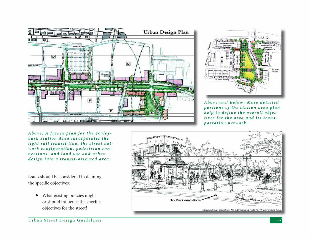
57Ur b a n S t r e e t D e s i g n G u i d e l i n e s
Ab o v e : A f u t u r e p l a n f o r t h e S c a l e y -b a r k S t a t i o n Ar e a i n c o r p o r a t e s t h e l i g h t r a i l t r a n s i t l i n e , t h e s t r e e t n e t -w o r k c o n f i g u r a t i o n , p e d e s t r i a n c o n -n e c t i o n s , a n d l a n d u s e a n d u r b a n d e s i g n i n t o a t r a n s i t - o r i e n t e d a r e a .
Ab o v e a n d B e l o w : M o r e d e t a i l e d p o r t i o n s o f t h e s t a t i o n a r e a p l a n h e l p t o d e f i n e t h e o v e r a l l o b j e c -t i v e s f o r t h e a r e a a n d i t s t r a n s -p o r t a t i o n n e t w o r k .
issues should be considered in defi ning the specifi c objectives:
• What existing policies might or should infl uence the specifi c objectives for the street?
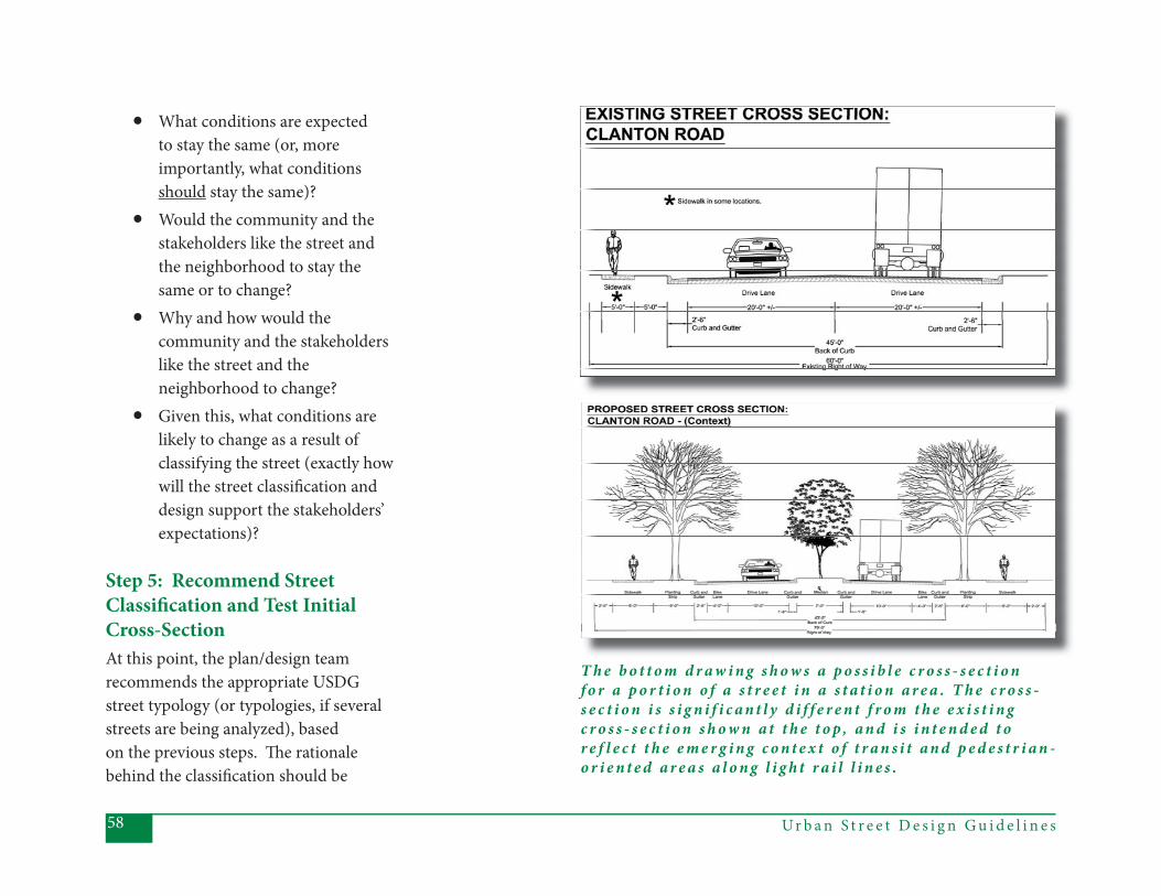
Ur b a n S t r e e t D e s i g n G u i d e l i n e s58
T h e b o t t o m d r a w i n g s h o w s a p o s s i b l e c r o s s - s e c t i o n f o r a p o r t i o n o f a s t r e e t i n a s t a t i o n a r e a . T h e c r o s s -s e c t i o n i s s i g n i f i c a n t l y d i f f e r e n t f r o m t h e e x i s t i n g c r o s s - s e c t i o n s h o w n a t t h e t o p , a n d i s i n t e n d e d t o r e f l e c t t h e e m e r g i n g c o n t e x t o f t r a n s i t a n d p e d e s t r i a n -o r i e n t e d a r e a s a l o n g l i g h t r a i l l i n e s .
• What conditions are expected to stay the same (or, more importantly, what conditions should stay the same)?
• Would the community and the stakeholders like the street and the neighborhood to stay the same or to change?
• Why and how would the community and the stakeholders like the street and the neighborhood to change?
• Given this, what conditions are likely to change as a result of classifying the street (exactly how will the street classifi cation and design support the stakeholders’ expectations)?
Step 5: Recommend Street Classifi cation and Test Initial Cross-SectionAt this point, the plan/design team recommends the appropriate USDG street typology (or typologies, if several streets are being analyzed), based on the previous steps. Th e rationale behind the classifi cation should be
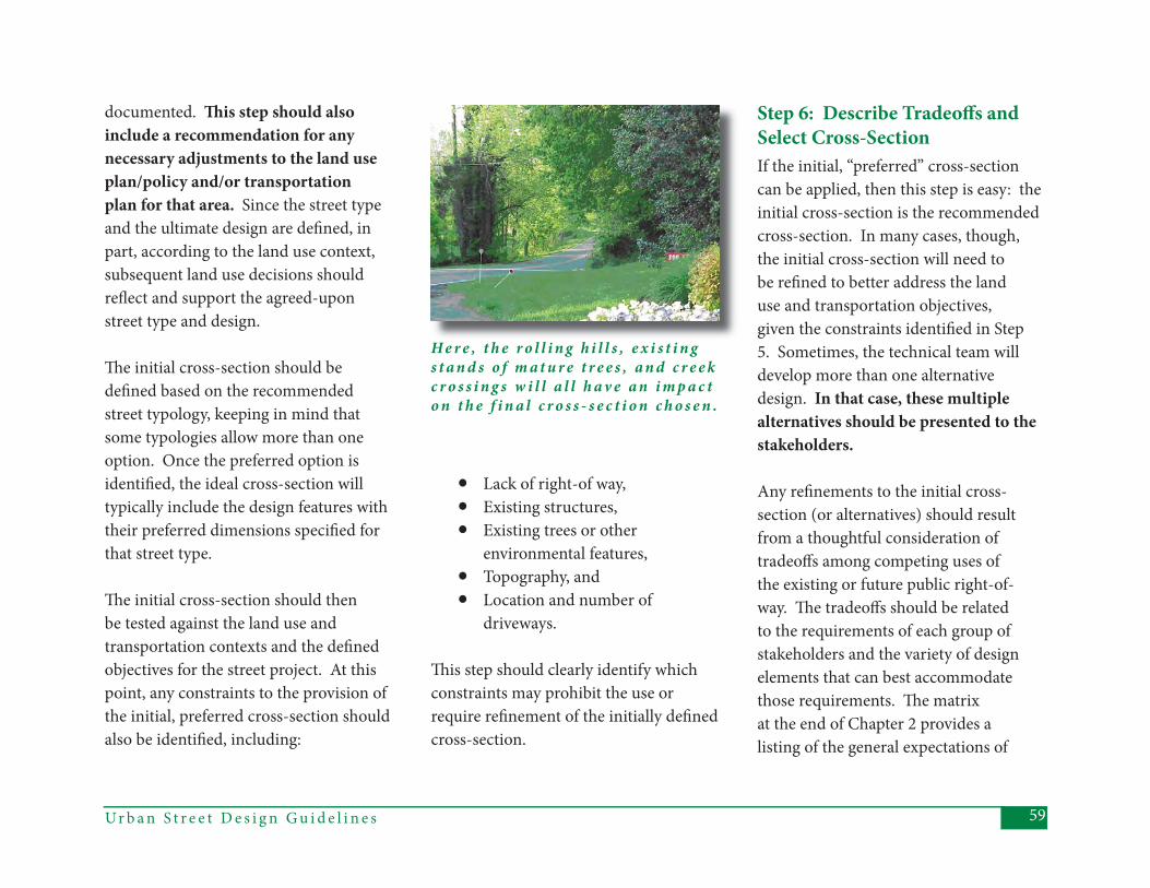
59Ur b a n S t r e e t D e s i g n G u i d e l i n e s
H e r e , t h e r o l l i n g h i l l s , e x i s t i n g s t a n d s o f m a t u r e t r e e s , a n d c r e e k c r o s s i n g s w i l l a l l h a v e a n i m p a c t o n t h e f i n a l c r o s s - s e c t i o n c h o s e n .
documented. Th is step should also include a recommendation for any necessary adjustments to the land use plan/policy and/or transportation plan for that area. Since the street type and the ultimate design are defi ned, in part, according to the land use context, subsequent land use decisions should refl ect and support the agreed-upon street type and design.
Th e initial cross-section should be defi ned based on the recommended street typology, keeping in mind that some typologies allow more than one option. Once the preferred option is identifi ed, the ideal cross-section will typically include the design features with their preferred dimensions specifi ed for that street type.
Th e initial cross-section should then be tested against the land use and transportation contexts and the defi ned objectives for the street project. At this point, any constraints to the provision of the initial, preferred cross-section should also be identifi ed, including:
• Lack of right-of way,• Existing structures, • Existing trees or other
environmental features,• Topography, and• Location and number of
driveways.
Th is step should clearly identify which constraints may prohibit the use or require refi nement of the initially defi ned cross-section.
Step 6: Describe Tradeoff s and Select Cross-SectionIf the initial, “preferred” cross-section can be applied, then this step is easy: the initial cross-section is the recommended cross-section. In many cases, though, the initial cross-section will need to be refi ned to better address the land use and transportation objectives, given the constraints identifi ed in Step 5. Sometimes, the technical team will develop more than one alternative design. In that case, these multiple alternatives should be presented to the stakeholders.
Any refi nements to the initial cross-section (or alternatives) should result from a thoughtful consideration of tradeoff s among competing uses of the existing or future public right-of-way. Th e tradeoff s should be related to the requirements of each group of stakeholders and the variety of design elements that can best accommodate those requirements. Th e matrix at the end of Chapter 2 provides a listing of the general expectations of
Ur b a n S t r e e t D e s i g n G u i d e l i n e s60
various stakeholders about streets and the elements that might achieve those expectations. At the least, the requirements and elements listed in that matrix should be considered in any tradeoff discussion, though that list should not be considered comprehensive.
Th e specifi c method of evaluating the tradeoff s is left open to the plan/design team, as long as the method/discussion/analysis is documented. All perspectives should receive equal consideration and accountability in the plan/design process. Proper documentation will also generate information useful for future street design projects that might have similar characteristics, objectives, or constraints.
Once the tradeoff s are evaluated, the team should be able to develop a refi ned cross-section and suggested design treatments. Th e culmination of all of the previous steps, including any additional stakeholder comments, should provide suffi cient rationale to select the design alternative that best matches the context and future expectations for the street project.
F i n a l C o m m e n t s o n t h e S i x S t e p sTh e steps outlined in this chapter suggest that there is a linear process leading to an ideal solution. Realistically, in some instances the process may not follow the exact sequence described above. Some information may not be available or even be applicable for some conditions. Th e intent, though, is to ensure that the existing and future contexts are given adequate consideration, that any related plans are modifi ed to refl ect the outcome, and that all perspectives are given equal consideration in the process.
Th e same approach described here for large-scale street projects can be applied to smaller-scale or short-term projects or processes. In those cases, an “abbreviated” version of the six steps can be used to reach decisions that will necessarily involve a shorter timeframe or fewer stakeholders, but for which it is still important to consider all perspectives and document any necessary tradeoff s. Th e intent is to
apply this thought process to the design of our emerging complete street network, whether through the full six-step process, or through the abbreviated version.
61Ur b a n S t r e e t D e s i g n G u i d e l i n e s
4 . S E G M E N T S
The previous chapters of this docu-ment have focused on the need for,
objectives of, and methods for applying Charlotte’s new Urban Street Design Guidelines. Th is chapter contains the detailed guidelines for the street seg-ments or blocks: those portions of the street between intersections (Chapter 5 provides guidelines for the intersections).
Th e following sections describe, for each of the street types, the design elements that should be included, with the pre-ferred dimensions of those elements along the segment portions of a street. Each of the detailed descriptions includ-ed in this chapter is intended to accom-plish the overall objective of providing safe, functional, multi-modal streets that serve all users - i.e., complete streets.
While the sections in this chapter de-scribe how to design various types of street segments, it is important to re-member that any given street, particu-larly if it is a thoroughfare, will traverse
several types of land uses. Th erefore, this chapter contains information about how to match relevant street elements to the existing or desired land uses along the street. Th is chapter does not, however, provide specifi c information about de-signing the transitions between diff erent street types. Th ese transitions will most likely occur at intersections, which are described in detail in the next chapter. Th e reader should refer to both chapters when designing a segment or an intersec-tion that transitions between street types.
Sections 4.1 - 4.4:Non-Local Streets
Sections 4.1-4.4 describe the guidelines for segments on non-local streets (Main Streets, Avenues, Boulevards, and Park-ways). Th e information in these sections is detailed, but not entirely prescriptive. Th e design team should use this detailed information about dimensions in con-junction with the design method and tradeoff analyses outlined in Chapter 3.
Th e cross-section diagrams do not show dimensions for these non-local street types, since the focus is on understand-ing and evaluating the tradeoff s among the various (possibly competing) uses of the right-of-way.
Many of the design element dimensions described in this chapter refer to evaluat-ing tradeoff s in a “constrained” environ-ment. Design teams should take care to consider what constitutes a “constraint.” For example, when a streetscape is being designed with existing buildings, those buildings might constitute a constraint. However, when a street is built “from scratch” or when new buildings are be-ing constructed along an existing street, these buildings would not typically be considered a constraint. In those cases, the preferred dimensions should general-ly be provided, or the design team should justify why they are not.
Ur b a n S t r e e t D e s i g n G u i d e l i n e s62
Block Lengths for Non-Local Streets
One of the design elements described in Sections 4.1 – 4.4 is block length, which refers to the expected spacing of cross-streets along a given street type. Th e relationship between block length and street network density, as well as the many advantages of a dense network are described in more detail in the section below titled “Block Lengths for Local Streets.” It is important, however, to note that the spacing of non-local streets (Main Streets, Avenues, Boulevards, and Park-ways) is not described in this chapter. Th at is to say, there are no expected distances defi ned between streets that are likely to function as thoroughfares. In most areas of Charlotte, Avenues, Boulevards, or Parkways would not be spaced within one or several blocks of each other. Unless specifi cally defi ned in an area plan, these types of streets would typically be ½ mile or further from each other.
Sections 4.5 – 4.7:Local Streets
Sections 4.5-4.7 describe the guidelines for segments of local streets (Residential, Offi ce/Commercial, and Industrial). Th e elements and dimensions described for these local streets are more prescrip-tive than those for the non-local streets, since local streets are typically designed and built through the land development process. Although most of the design el-ements for Local Streets are described in Sections 4.5 – 4.7, the recommendations for block lengths are described here, because block length is critical to creat-ing the street network that will meet the many objectives defi ned for Charlotte’s streets.
Block Lengths for Local Streets
Block length is a critical component of the street network. In general, the shorter the block length, the denser the street network. A dense street network provides:
• capacity for vehicle traffi c, • multiple route options,
• shorter trip options, • future development fl exibility, • more dispersed traffi c fl ows, and • more opportunities for traffi c calm-
ing.
Shorter blocks create a high degree of connectivity to help ensure that vehicular traffi c does not become focused on only one or two streets. Shorter blocks also create a better walking environment, by providing numerous direct and indirect routes throughout neighborhoods and between land uses. In the Local Street network, frequently spaced intersections created by shorter blocks can also serve as a form of traffi c calming.
Th e general intent of the block lengths recommended here is to ensure that the density of the Local Street network ap-propriately refl ects development density/intensity and provides the type of net-work structure that has stood the test of time elsewhere in the City. To integrate the street network with development density/intensity, the block lengths are organized by their geographic location relative to Charlotte’s Centers, Cor-ridors and Wedges growth framework,
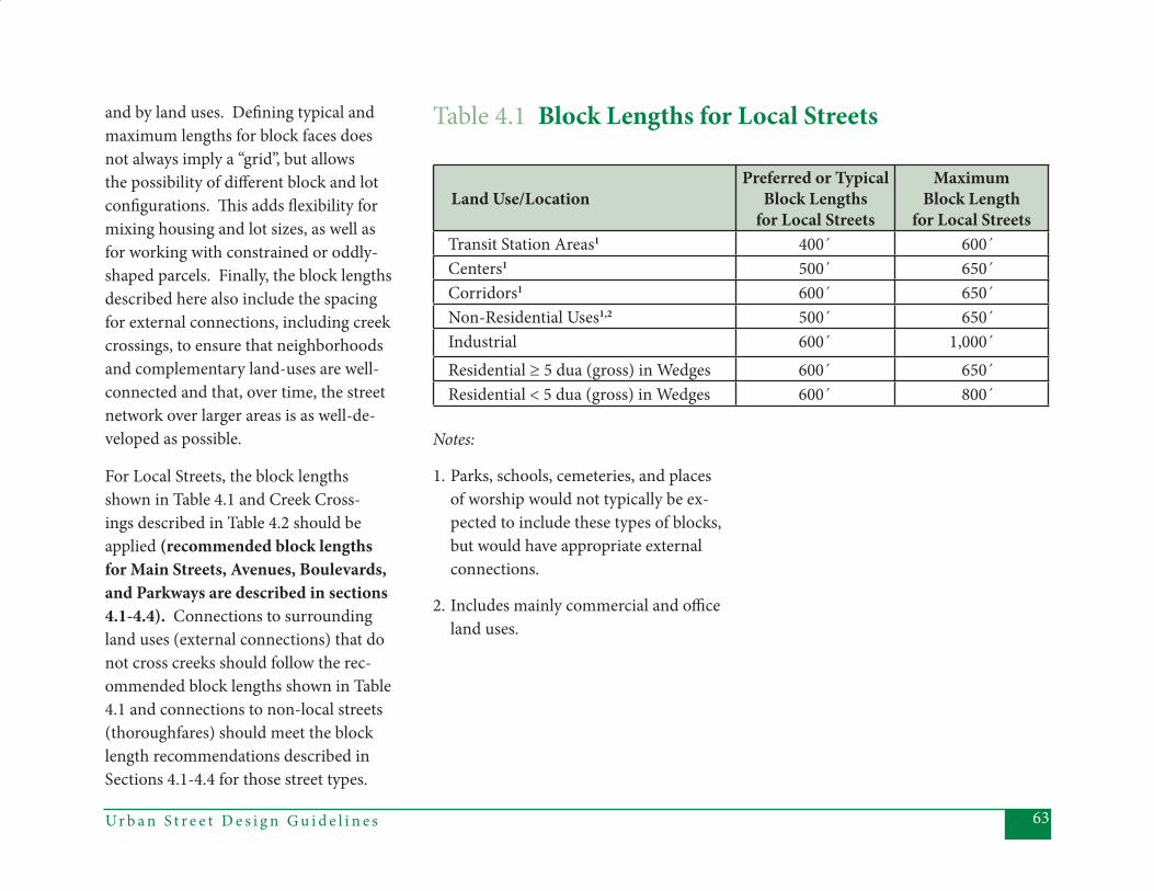
63Ur b a n S t r e e t D e s i g n G u i d e l i n e s
and by land uses. Defi ning typical and maximum lengths for block faces does not always imply a “grid”, but allows the possibility of diff erent block and lot confi gurations. Th is adds fl exibility for mixing housing and lot sizes, as well as for working with constrained or oddly-shaped parcels. Finally, the block lengths described here also include the spacing for external connections, including creek crossings, to ensure that neighborhoods and complementary land-uses are well-connected and that, over time, the street network over larger areas is as well-de-veloped as possible.
For Local Streets, the block lengths shown in Table 4.1 and Creek Cross-ings described in Table 4.2 should be applied (recommended block lengths for Main Streets, Avenues, Boulevards, and Parkways are described in sections 4.1-4.4). Connections to surrounding land uses (external connections) that do not cross creeks should follow the rec-ommended block lengths shown in Table 4.1 and connections to non-local streets (thoroughfares) should meet the block length recommendations described in Sections 4.1-4.4 for those street types.
Table 4.1 Block Lengths for Local Streets
Land Use/LocationPreferred or Typical
Block Lengthsfor Local Streets
Maximum Block Length
for Local StreetsTransit Station Areas1 400´ 600´Centers1 500´ 650´Corridors1 600´ 650´Non-Residential Uses1,2 500´ 650´Industrial 600´ 1,000´Residential ≥ 5 dua (gross) in Wedges 600´ 650´Residential < 5 dua (gross) in Wedges 600´ 800´
Notes:
1. Parks, schools, cemeteries, and places of worship would not typically be ex-pected to include these types of blocks, but would have appropriate external connections.
2. Includes mainly commercial and offi ce land uses.
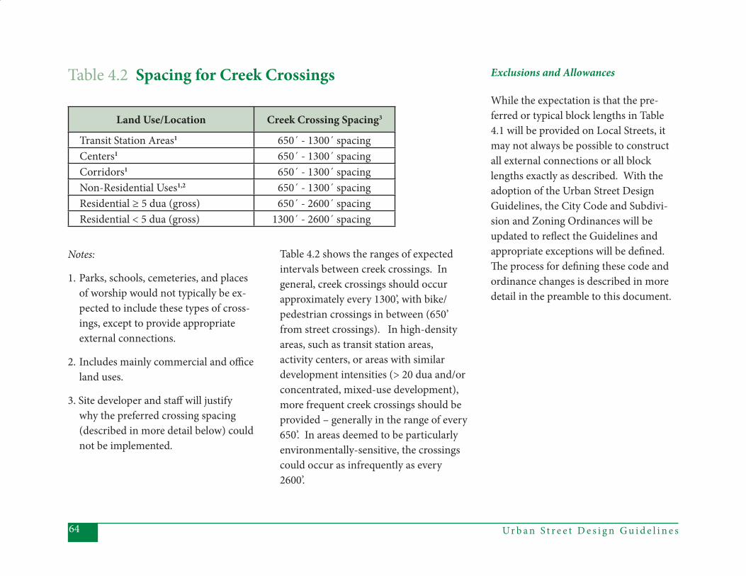
Ur b a n S t r e e t D e s i g n G u i d e l i n e s64
Exclusions and Allowances
While the expectation is that the pre-ferred or typical block lengths in Table 4.1 will be provided on Local Streets, it may not always be possible to construct all external connections or all block lengths exactly as described. With the adoption of the Urban Street Design Guidelines, the City Code and Subdivi-sion and Zoning Ordinances will be updated to refl ect the Guidelines and appropriate exceptions will be defi ned. Th e process for defi ning these code and ordinance changes is described in more detail in the preamble to this document.
Table 4.2 Spacing for Creek Crossings
Land Use/Location Creek Crossing Spacing3
Transit Station Areas1 650´ - 1300´ spacingCenters1 650´ - 1300´ spacingCorridors1 650´ - 1300´ spacingNon-Residential Uses1,2 650´ - 1300´ spacingResidential ≥ 5 dua (gross) 650´ - 2600´ spacingResidential < 5 dua (gross) 1300´ - 2600´ spacing
Table 4.2 shows the ranges of expected intervals between creek crossings. In general, creek crossings should occur approximately every 1300’, with bike/pedestrian crossings in between (650’ from street crossings). In high-density areas, such as transit station areas, activity centers, or areas with similar development intensities (> 20 dua and/or concentrated, mixed-use development), more frequent creek crossings should be provided – generally in the range of every 650’. In areas deemed to be particularly environmentally-sensitive, the crossings could occur as infrequently as every 2600’.
Notes:
1. Parks, schools, cemeteries, and places of worship would not typically be ex-pected to include these types of cross-ings, except to provide appropriate external connections.
2. Includes mainly commercial and offi ce land uses.
3. Site developer and staff will justify why the preferred crossing spacing (described in more detail below) could not be implemented.

65Ur b a n S t r e e t D e s i g n G u i d e l i n e s
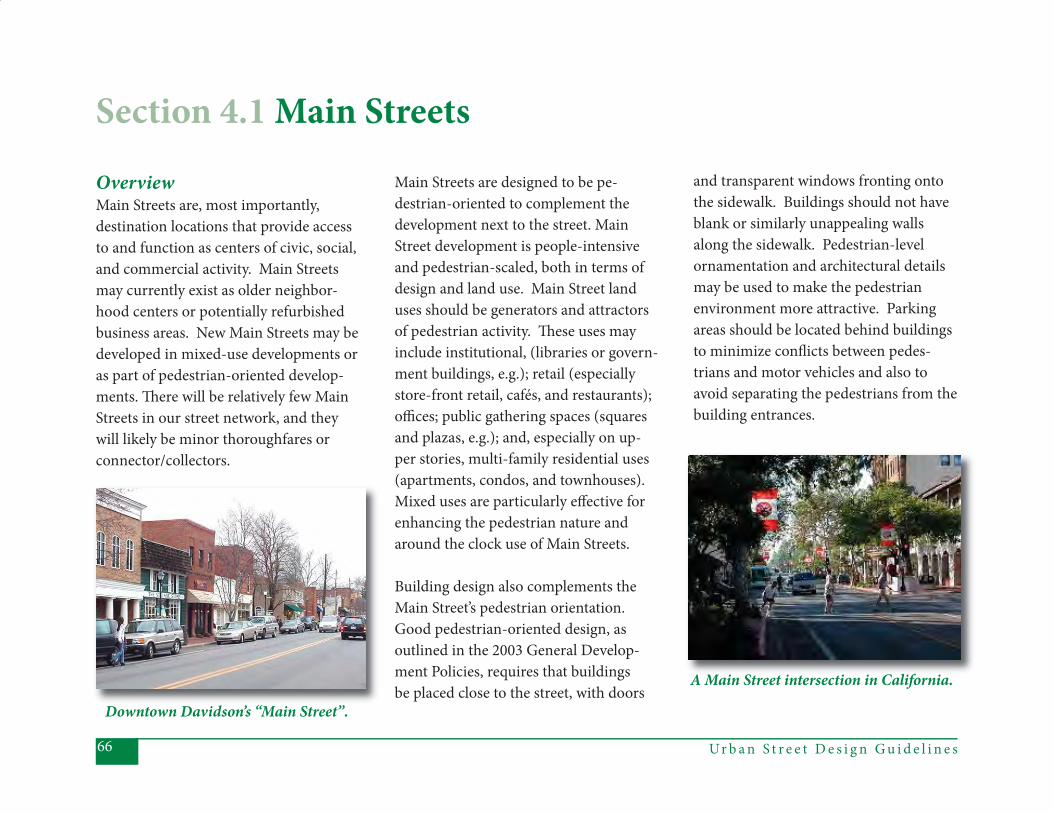
Ur b a n S t r e e t D e s i g n G u i d e l i n e s66
OverviewMain Streets are, most importantly, destination locations that provide access to and function as centers of civic, social, and commercial activity. Main Streets may currently exist as older neighbor-hood centers or potentially refurbished business areas. New Main Streets may be developed in mixed-use developments or as part of pedestrian-oriented develop-ments. Th ere will be relatively few Main Streets in our street network, and they will likely be minor thoroughfares or connector/collectors.
Main Streets are designed to be pe-destrian-oriented to complement the development next to the street. Main Street development is people-intensive and pedestrian-scaled, both in terms of design and land use. Main Street land uses should be generators and attractors of pedestrian activity. Th ese uses may include institutional, (libraries or govern-ment buildings, e.g.); retail (especially store-front retail, cafés, and restaurants); offi ces; public gathering spaces (squares and plazas, e.g.); and, especially on up-per stories, multi-family residential uses (apartments, condos, and townhouses). Mixed uses are particularly eff ective for enhancing the pedestrian nature and around the clock use of Main Streets.
Building design also complements the Main Street’s pedestrian orientation. Good pedestrian-oriented design, as outlined in the 2003 General Develop-ment Policies, requires that buildings be placed close to the street, with doors
and transparent windows fronting onto the sidewalk. Buildings should not have blank or similarly unappealing walls along the sidewalk. Pedestrian-level ornamentation and architectural details may be used to make the pedestrian environment more attractive. Parking areas should be located behind buildings to minimize confl icts between pedes-trians and motor vehicles and also to avoid separating the pedestrians from the building entrances.
Downtown Davidson’s “Main Street”.
A Main Street intersection in California.
Section 4.1 Main Streets

67Ur b a n S t r e e t D e s i g n G u i d e l i n e s
Pedestrian-oriented features on Main Streets include generous sidewalks and amenity zones. An amenity zone pro-vides space for street furniture, trees, pedestrian-scale lighting and signs, pub-lic art, and last, but not least, maintains unobstructed sidewalk space for pedes-trians. To minimize confl icts between pedestrians and vehicles, driveways on Main Streets are restricted or very lim-ited – motor vehicle access is ideally provided behind the buildings.
Main Streets’ block lengths are ideally no more than 400’, to provide frequent locations for pedestrian crossings and numerous connections to adjacent streets. Main Streets will typically not be long streets. Th ey function best at total lengths of 1000’-1500’, which is consid-ered a comfortable walking distance.
Because Main Streets serve as pedestrian-oriented activity centers, walking receives the highest priority of all the transport modes. Although they also serve transit, bicyclists, and automobiles, Main Streets are designed to provide the highest level of pedestrian comfort, access, and se-curity of all of Charlotte’s (non-local) street types. For example, Main Streets are kept relatively narrow to provide easy and safe pedestrian crossings, and pri-ority is given to pedestrians’ safety and convenience instead of motor vehicles’ speeds and volumes. Traffi c speeds are maintained at no more than 25 mph, to ensure that vehicle speeds are compatible with the pedestrian environment. Th ey are typically 2 lanes with on-street park-ing, but Main Streets may also include a 3rd, center turn lane. Roadway capacity for vehicles is not expanded to maintain free fl ows and congestion is accepted as a positive, traffi c calming aspect of the Main Street environment.
On-street parking is encouraged, to provide traffi c calming and convenient parking for Main Street land uses. Spe-cial lanes for bicyclists are not typically provided, since bicyclists can travel in mixed traffi c due to the low operating speeds.
Because of the nature of their land uses and pedestrian-oriented design, Main Streets are also ideal settings for transit service. Th e short block lengths and heavy pedestrian traffi c suggest that tran-sit stops can be closely spaced.
Main Streets
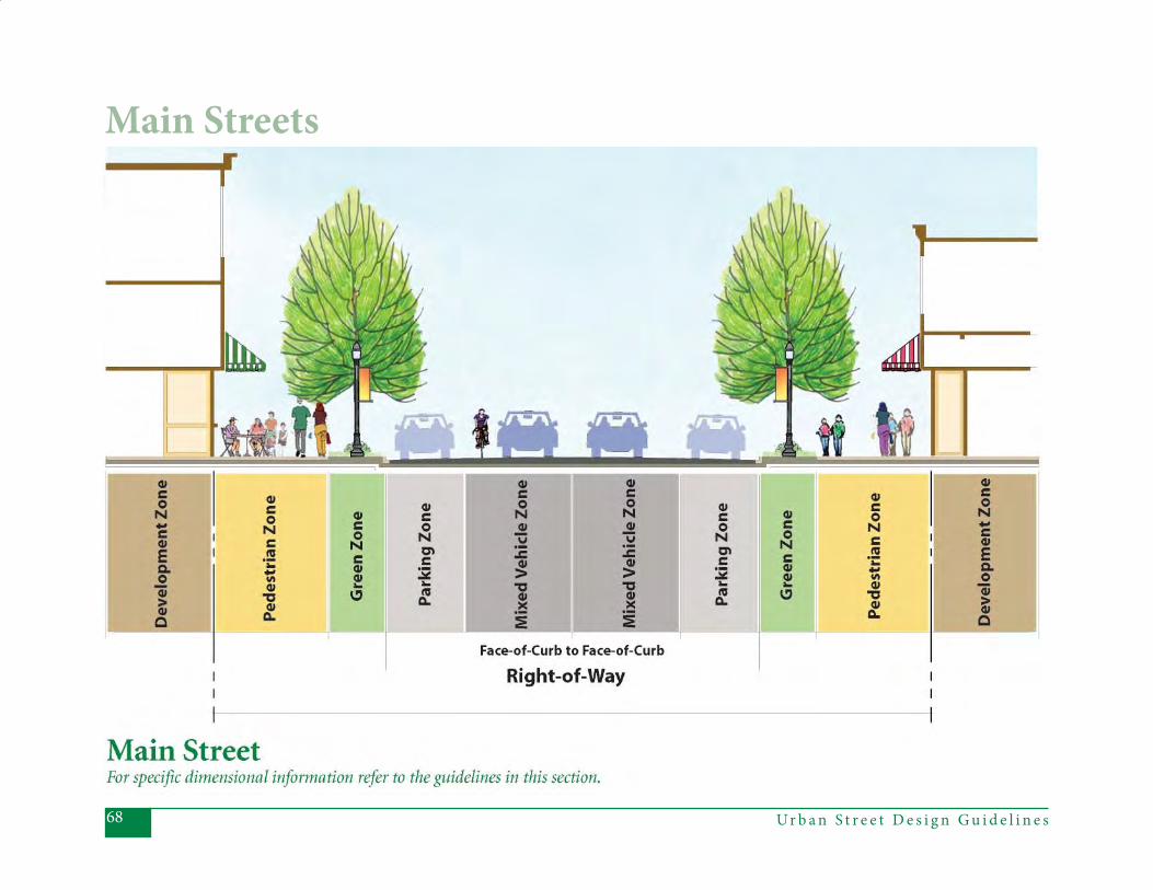
Ur b a n S t r e e t D e s i g n G u i d e l i n e s68
Main Streets
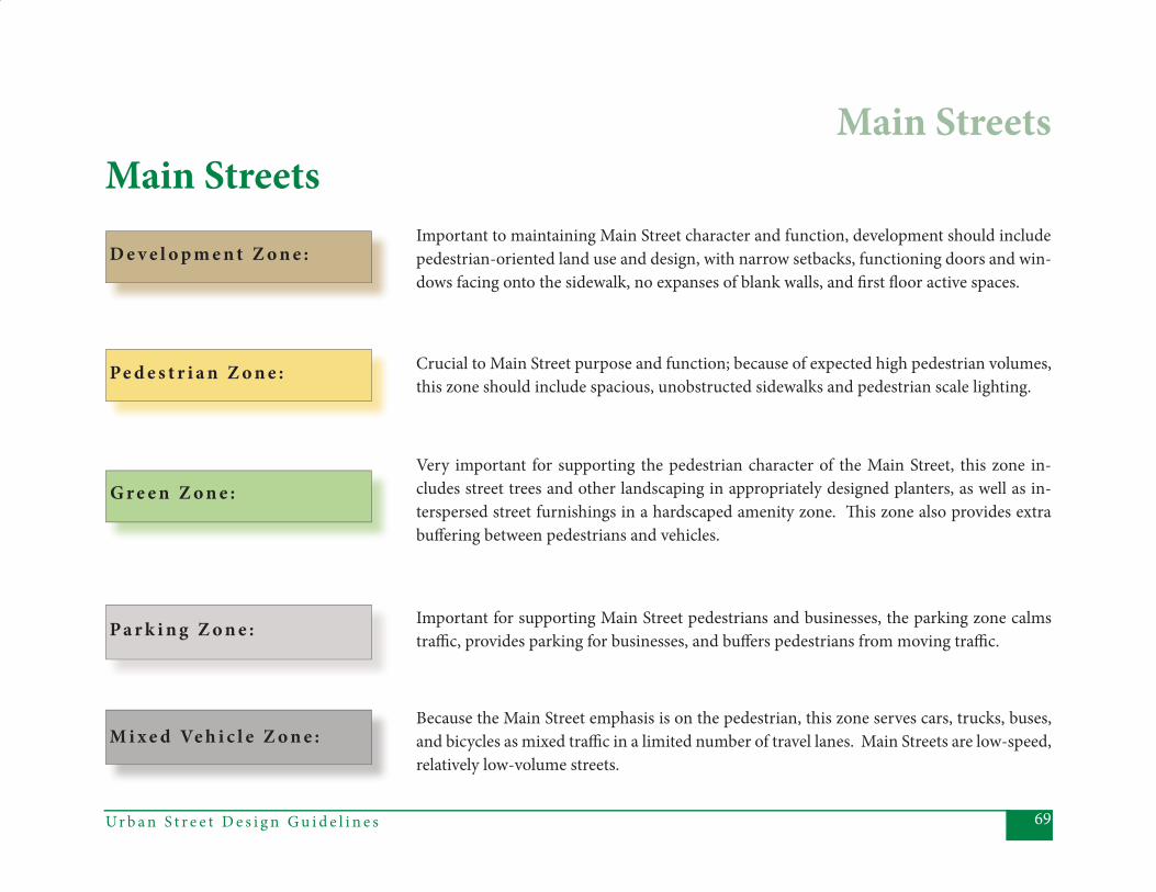
69Ur b a n S t r e e t D e s i g n G u i d e l i n e s
Because the Main Street emphasis is on the pedestrian, this zone serves cars, trucks, buses, and bicycles as mixed traffi c in a limited number of travel lanes. Main Streets are low-speed, relatively low-volume streets.
D e v e l o p m e n t Z o n e :
Main StreetsImportant to maintaining Main Street character and function, development should include pedestrian-oriented land use and design, with narrow setbacks, functioning doors and win-dows facing onto the sidewalk, no expanses of blank walls, and fi rst fl oor active spaces.
Crucial to Main Street purpose and function; because of expected high pedestrian volumes, this zone should include spacious, unobstructed sidewalks and pedestrian scale lighting.
Pe d e s t r i a n Z o n e :
G r e e n Z o n e :Very important for supporting the pedestrian character of the Main Street, this zone in-cludes street trees and other landscaping in appropriately designed planters, as well as in-terspersed street furnishings in a hardscaped amenity zone. Th is zone also provides extra buff ering between pedestrians and vehicles.
Important for supporting Main Street pedestrians and businesses, the parking zone calms traffi c, provides parking for businesses, and buff ers pedestrians from moving traffi c. P a r k i n g Z o n e :
M i x e d Ve h i c l e Z o n e :
Main Streets
Ur b a n S t r e e t D e s i g n G u i d e l i n e s70
Priority Elements:• Maximum Posted Speed – 25 mph - equal to design speed and comfort- able for both bicyclists and pedestrians.
• Number of Th rough Lanes – Typically, 1 in each direction (2 total). Where short block lengths (400’ or less) are maintained, an alternative “typical” design would provide 1 lane in each direction, with a center lane used as back-to-back turn lanes (3 total). Where longer blocks are necessary, the 3rd lane is still allowable, but should be intermittently broken with land-
scaped islands or, in rare cases, pedes-trian refuges or a median. Four lanes are inappropriate. In cases where exist-ing 4 lane sections are deemed to be Main Streets, the extra lane width can be used to accommodate parking or
other elements, thereby “dieting” to an ideal Main Street cross-section.
• Lane Width – Should typically allow 13’ for lanes next to parking to main- tain the necessary clear distance for opening car doors and to accommo- date commercial vehicles – in the 3 lane situation, 10’ is suitable for the third lane. In constrained conditions, lanes next to parking should not be less than 12’ wide. In the case of angled parking, the travel lane should be at least 13’ wide.
• Sidewalks – Sidewalks are the most important element on a Main Street, because pedestrians are the priority - sidewalk width should be at least 10’ , unobstructed. In constrained circum-
stances and where uses such as sidewalk dining are desirable, the unobstructed portion of the sidewalk can be reduced to 8’, which allows for some intrusion into the sidewalk area by adjacent outdoor dining areas, while maintaining a comfortable walking space. Even in those cases, however, no railings
or other permanent or semi-permanent fi xtures should encroach into the 10’ sidewalk width. Even in constrained conditions, sidewalks should not be less than 6’ unobstructed width.
• Sidewalk Amenity Zone – Th is zone enhances the pedestrian environment along a Main Street. It should be 8’ wide (not including the sidewalk). Th is width provides space for street trees, streetlights, benches, transit amenities, and trash receptacles. Even in constrained conditions, the mini- mum sidewalk amenity zone is 5’ (without trees) or 6’ (with small maturing trees).
• On-Street Parking Lanes – On-street parking supports businesses and pro- vides a buff er between pedestrians and traffi c – 7’ from the face-of-curb is ideal to minimize street widths, to provide a small measure of clear width for opening doors, and to provide ad-
Main Streets
71Ur b a n S t r e e t D e s i g n G u i d e l i n e s
equate travel lane width for shared use by bicycles, transit, autos, and com- mercial vehicles. Even in constrained conditions, on-street parking lanes should not be less than 7’ wide.
• Curb and Gutter – Main Streets will typically have 6” vertical curb, in keeping with the urban context.
• Curb Extensions – Should be provided at mid-block crossing points. Th e width should match the width of on-street parking lanes (7’ typical). Curb extensions provide for reduced pedestrian crossing distances and increased pedestrian visibility when crossing the street – they also add space for trees, other landscaping, and street furniture.
• Lighting – Since pedestrian activity is expected and encouraged in Main Street locations, decorative pedestrian- scale lighting should be provided.
Pedestrian lighting should be suffi cient to illuminate the sidewalk, as well as to provide for pedestrian visibility and safety from crime. Pedestrian lighting should be placed so that light is not obscured by branch- es and leaves. In some cases, the pedestrian-scale lighting can also be suffi cient for street lighting. Where street lighting is provided, sharp cut- off , ornamental fi xtures should be used rather than Cobraheads.
• Block Length – Typically, should not exceed 400’. Short block lengths provide for traffi c calming and more frequent and accessible crossing points for pedestrians, as well as improved connectivity for all travel modes.
Main Streets
Ur b a n S t r e e t D e s i g n G u i d e l i n e s72
Main Streets
Other Elements to Consider• Utilities – To preserve sidewalk capacity for pedestrians, maintain a clear zone per ADA requirements, and allow larger trees and other aesthetic treatments (thereby enhancing the pe- destrian nature of Main Streets), utilities should be placed under- ground, wherever feasible. If un- derground placement is not feasible, the next most preferable location is at the back of property. If poles must be located along the street frontage, they should be placed in the sidewalk amenity zone. Under no circumstanc- es should they be placed in the side- walk. Utility poles should be consoli- dated where possible, with redundant poles removed in retrofi t situations.
• Traffi c Calming – Typically not neces- sary if other elements are in place, but may be used to maintain desired speeds. See CDOT’s Traffi c Calming Report for more details on appropriate applications of traffi c calming tools.
• Mid-Block Pedestrian Crossings - Should be considered on blocks of
more than 600’ to ensure accessible pedestrian crossing points. Curb ex- tensions and high visibility markings should be provided at these mid-block crossing locations. See CDOT’s Mid- Block Crossing Policy for more infor- mation on safe crossings.
• Angled Parking – Allowable in special cases where adequate right-of-way ex- ists, parking demand exceeds the ca- pacity of parallel parking, and traffi c volumes and speeds are low enough for safe operation. Angled parking requires 20’ for the parking, next to a 13’ travel lane. Back-in angled park- ing may be used in situations where it is deemed necessary, due to in- creased visibility for the driver.
• Medians – Medians are typically inap- propriate in a Main Street, because they increase the crossing distance re-
quired for pedestrians. However, they may be allowable in circum- stances requiring special treatment for aesthetics, open space needs, pedestrian safety, or to provide in- termittent breaks in the third lane on longer, 3 lane segments. If pro- vided, should be a minimum of 6’, and paved at appropriate locations to facili- tate their use for mid-block crossing.
• Median Planting – If median is pro- vided (see above), landscaping should be provided, except in portions of the median designated for pedestrian ac- cess. Where provided, plants should be no higher than 30 inches and tree limbs should fall no lower than 6’ to provide a “visibility zone” for pedestri- ans and motorists.
73Ur b a n S t r e e t D e s i g n G u i d e l i n e s
Inappropriate Elements:• Bus Stops/Bus Zones – Excluded in segments, because block lengths are short and stops will typically be lo- cated at the intersections. See Chapter 5 for details on bus stops at Main Street intersections.
• Bike Lanes – Excluded to minimize street widths and confl icts between bicyclists and parked cars – bicyclists can operate in mixed traffi c due to the low operating speeds and wide lanes on Main Streets.
• Planting Strips – Excluded to maxi- mize sidewalk space for pedestrians and to provide unrestricted access from parking to the sidewalk. Plant- ing would typically be street trees in appropriately designed planters, lo- cated within the sidewalk amenity zone.
• Driveways – Excluded to eliminate confl icts between pedestrians and motor vehicles turning into businesses. Service access should be at the rear of the commercial properties. In constrained conditions where drive- ways cannot be excluded, shared driveways are encouraged.
• Pedestrian Refuge – Since Main Streets have short blocks (providing frequent crossing opportunities at intersec- tions), pedestrian refuges are typically not recommended. However, refuges may be allowable under certain cir- cumstances, as described in this sec- tion under “Number of Th rough Lanes”, and “Medians”, and also in Section 5.1: “Main Street Intersections”.
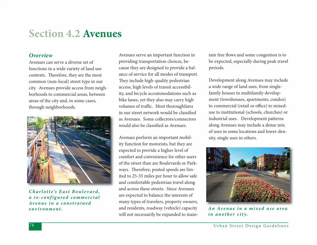
Ur b a n S t r e e t D e s i g n G u i d e l i n e s74
OverviewAvenues can serve a diverse set of functions in a wide variety of land use contexts. Th erefore, they are the most common (non-local) street type in our city. Avenues provide access from neigh-borhoods to commercial areas, between areas of the city and, in some cases, through neighborhoods.
Avenues serve an important function in providing transportation choices, be-cause they are designed to provide a bal-ance of service for all modes of transport. Th ey include high-quality pedestrian access, high levels of transit accessibil-ity, and bicycle accommodations such as bike lanes, yet they also may carry high volumes of traffi c. Most thoroughfares in our street network would be classifi ed as Avenues. Some collectors/connectors would also be classifi ed as Avenues.
Avenues perform an important mobil-ity function for motorists, but they are expected to provide a higher level of comfort and convenience for other users of the street than are Boulevards or Park-ways. Th erefore, posted speeds are lim-ited to 25-35 miles per hour to allow safe and comfortable pedestrian travel along and across these streets. Since Avenues are expected to balance the interests of many types of travelers, property owners, and residents, roadway (vehicle) capacity will not necessarily be expanded to main-
tain free fl ows and some congestion is to be expected, especially during peak travel periods.
Development along Avenues may include a wide range of land uses, from single-family houses to multifamily develop-ment (townhouses, apartments, condos) to commercial (retail or offi ce) to mixed-use to institutional (schools, churches) or industrial uses. Development patterns along Avenues may include a dense mix of uses in some locations and lower-den-sity, single uses in others.
C h a r l o t t e ’s E a s t B o u l e v a r d , a r e - c o n f i g u r e d c o m m e r c i a lAv e n u e i n a c o n s t r a i n e d e n v i r o n m e n t . A n Av e n u e i n a m i x e d u s e a r e a
i n a n o t h e r c i t y.
Section 4.2 Avenues
75Ur b a n S t r e e t D e s i g n G u i d e l i n e s
Although land uses may vary greatly, certain design elements help to provide the best access for pedestrians and main-tain the desired modal balance along Avenues. In keeping with good design practices and as outlined in the 2003 General Development Policies, non-residential buildings on Avenues should typically be oriented toward the street and located closer to the street than on Boulevards. Windows and doors should front onto the street, with direct pedes-trian access to the streetfront sidewalk. Parking should generally be located to the rear or sides of buildings or, in some cases, on-street. If parking is located between the street and the building, it should generally be no more than one row, to avoid large expanses of parking that separate buildings from the side-walks. Residential development, particu-larly single family, may be located further from (but should still face) the street, with direct pedestrian access to the streetfront sidewalk. For both residen-
tial and non-residential uses, blank walls and non-transparent windows should be avoided along pedestrian areas, to help provide for pedestrian comfort, security, and points of interest.
Since they serve so many functions and contexts, there are a number of alterna-tive Avenue cross-sections and design teams should carefully review the infor-mation on design elements provided later in this section. Avenues can have two, three or four lanes. Continuous medians are allowed on Avenues, but are not typical. Avenue block lengths should be limited to 600’ to provide frequent locations for safe pedestrian crossings, as well as frequent, convenient connections to adjacent neighborhoods. Signalized intersections are specially designed for pedestrian crossings, and refuge islands may also be provided between signalized intersections to allow pedestrian cross-ings. Common elements included in all Avenue cross-sections are sidewalks,
Avenues
planting strips or amenity zones with street trees, and bike lanes along both sides of the street.
Avenues provide an ideal transit environ-ment, since they are well designed for pe-destrians and provide many connections to adjacent neighborhoods. Transit stops are closely spaced, creating high levels of accessibility to service, and transit use is relatively heavy.
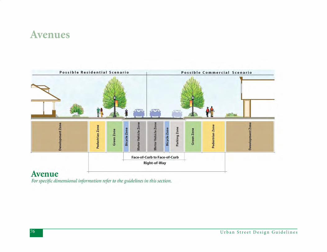
Ur b a n S t r e e t D e s i g n G u i d e l i n e s76
Avenues
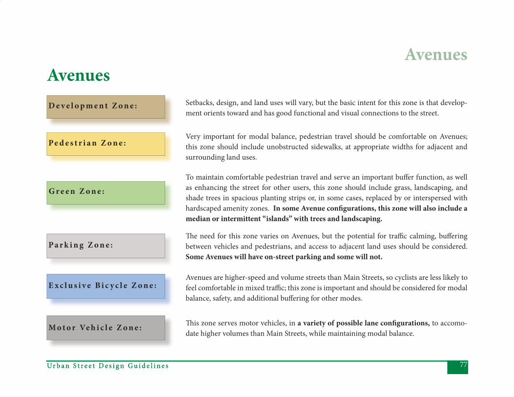
77Ur b a n S t r e e t D e s i g n G u i d e l i n e sUr b a n S t r e e t D e s i g n G u i d e l i n e s
Avenues
Th is zone serves motor vehicles, in a variety of possible lane confi gurations, to accomo-date higher volumes than Main Streets, while maintaining modal balance.
AvenuesSetbacks, design, and land uses will vary, but the basic intent for this zone is that develop-ment orients toward and has good functional and visual connections to the street.
Very important for modal balance, pedestrian travel should be comfortable on Avenues; this zone should include unobstructed sidewalks, at appropriate widths for adjacent and surrounding land uses.
To maintain comfortable pedestrian travel and serve an important buff er function, as well as enhancing the street for other users, this zone should include grass, landscaping, and shade trees in spacious planting strips or, in some cases, replaced by or interspersed with hardscaped amenity zones. In some Avenue confi gurations, this zone will also include a median or intermittent “islands” with trees and landscaping.
Th e need for this zone varies on Avenues, but the potential for traffi c calming, buff ering between vehicles and pedestrians, and access to adjacent land uses should be considered. Some Avenues will have on-street parking and some will not.
Avenues are higher-speed and volume streets than Main Streets, so cyclists are less likely to feel comfortable in mixed traffi c; this zone is important and should be considered for modal balance, safety, and additional buff ering for other modes.
E x c l u s i v e B i c y c l e Z o n e :
D e v e l o p m e n t Z o n e :
Pe d e s t r i a n Z o n e :
G r e e n Z o n e :
P a r k i n g Z o n e :
M o t o r Ve h i c l e Z o n e :
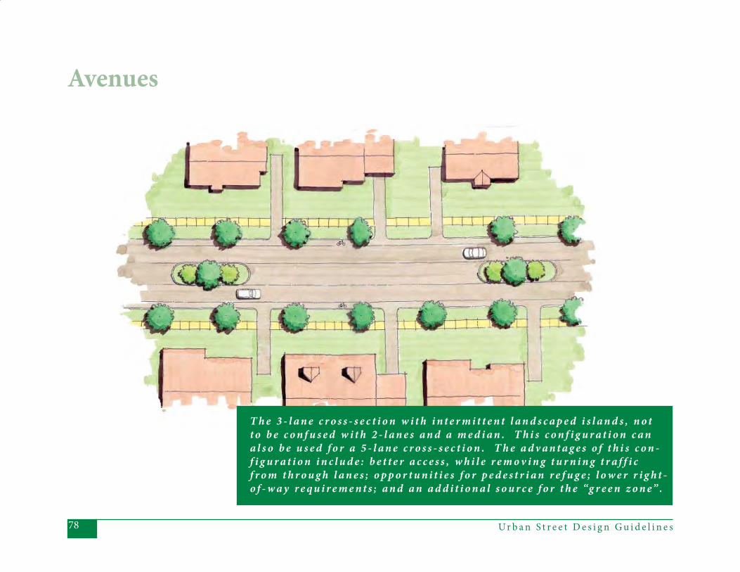
Ur b a n S t r e e t D e s i g n G u i d e l i n e s78
Avenues
T h e 3 - l a n e c r o s s - s e c t i o n w i t h i n t e r m i t t e n t l a n d s c a p e d i s l a n d s , n o t t o b e c o n f u s e d w i t h 2 - l a n e s a n d a m e d i a n . T h i s c o n f i g u r a t i o n c a n a l s o b e u s e d f o r a 5 - l a n e c r o s s - s e c t i o n . T h e a d v a n t a g e s o f t h i s c o n -f i g u r a t i o n i n c l u d e : b e t t e r a c c e s s , w h i l e r e m o v i n g t u r n i n g t r a f f i c f r o m t h r o u g h l a n e s ; o p p o r t u n i t i e s f o r p e d e s t r i a n r e f u g e ; l o w e r r i g h t -o f - w a y r e q u i r e m e n t s ; a n d a n a d d i t i o n a l s o u r c e f o r t h e “g r e e n z o n e” .
79Ur b a n S t r e e t D e s i g n G u i d e l i n e s
Priority Elements:Posted Speed – 25-30 mph preferred,
with 35 mph allowable. Th is is higher than Main Street speeds, but lower than Boulevard speeds, refl ecting the desire to provide reasonably safe and comfortable speeds for all modes.
Design Speed – 30-40 mph. Th e de- sign speed should be slightly higher than the posted speed, but not so high as to encourage speeding.
Number of Th rough Lanes – 1 in each direction (2 total), 1 in each direction plus an intermittently landscaped or (on short blocks) back-to-back turn- ing lane (3 total), 2 in each direction
(4 total), or 2 in each direction plus an intermittently landscaped turning lane (5 total). Th e diagram on the preced-ing page shows the general confi gura-tion of the 3-lane cross-section with the intermittent landscaped islands. Th e 5-lane cross-section is similar and this confi guration is generally prefer-
able to using a continuous median on Avenues. In special circumstances, may have 1 lane in each direction with a median.
• Lane Width – Should typically provide 10’ lanes, in addition to the gutter, where curb and gutter is present. 11’ lanes are acceptable. Twelve foot out-
side lanes should be provided where there is vertical curb, but no bike lane or on-street parking (to allow adequate clearance from curb for vehicles). Fourteen foot outside lanes are appro-priate where there is on-street parking but no bike lane. In the case of a me-dian- divided Avenue with only 1 lane in each direction, lanes should be 14’ wide.
• Bicycle Accommodations – Bicycle lanes are desirable on Avenues, to allow cyclists space to operate in a higher speed (though still urban) environ- ment. Th ey are especially important when needed to complete or continue
a bicycle network or when there are few other options for network con- tinuity. Bicycle lanes should be a minimum of 4’ wide and striped, in the absence of on-street parking. Where on-street parking exists, the bi- cycle lane should be 6’ wide and striped, to allow additional clear space between cyclists and opening car doors. Wide outside lanes may also be considered under constrained con- ditions.
• Sidewalks – Pedestrian activity is expected and encouraged along Av- enues. Th erefore, minimum 6’ wide unobstructed sidewalks should be provided on an Avenue. In areas that are currently or are planned to be pedestrian-oriented retail or mixed- use development (which should face onto the sidewalk), minimum 8’ wide unobstructed sidewalks should be pro- vided. In this case, a sidewalk amenity zone would typically be provided, as well.
Avenues
Ur b a n S t r e e t D e s i g n G u i d e l i n e s 79
Ur b a n S t r e e t D e s i g n G u i d e l i n e s80
•Planting Strips – Should be provided on Avenues to separate pedestrians from vehicles, provide a better walk- ing environment, and enhance the streetscape. Planting strips should ideally be 8’ minimum between curb and sidewalk to allow for grass and large maturing trees. Even in retrofi t or
constrained situations, the 8’ planting strip and large-maturing street trees should be the design priority. Th e design team should justify and docu-ment any deviations from the preferred width. In that case, the guidelines described in Section 4.5 (Planting Strips) for City-built retrofi ts (item 2) and developer-built infi ll projects (item 3) on Local Residential Streets will also apply to Avenues.
Where an 8’ planting strip cannot be provided (as described in Section 4.5, items 2 and 3), the following guidelines apply. For planting strips between 6’ and 8’, small maturing trees may be ac-
ceptable. If the planting strip is less than 5’, trees should not be planted in the planting strip, but shrubbery or ground
cover may be acceptable, depend- ing on maintenance needs. Even in constrained conditions, the planting strip should never be less than 3’. When
trees cannot be planted in the plant- ing strip, they should be planted in back of the sidewalk, if possible. Sight distance should also be consid-ered in the location and spacing of trees within the planting strip. Depending on factors such as street curvature, loca-tions of driveways, land use context, and planting strip width, a mix of species, tree sizes, or diff erent spacing may be necessary to maintain minimal sight distances for vehicles entering the street. In highly urban conditions, a sidewalk amenity zone should replace the plant-ing strip.
• Bus Stops – Most Avenues will have local and/or express bus service. Pre- ferred locations for bus stops, par-
ticularly for higher-volume bus stops, include cross streets (see Chapter 5: Intersections) and at mid-block crossings. Where there is full-time, dedicated on-street parking, bus stops must include curb extensions. At other locations, particularly in commercial or mixed-use areas, a hardscape pad for boarding and alighting passengers should be considered.
• Curb and Gutter – Should always have curb and gutter. 2’6’’ curb and gutter is typical, although 2’0 curb and gutter or 6’’ vertical curb may be used in constrained situations or in more urban environments. If a median exists, 1’6’’ curb and gutter is allowable on inside, median lanes.
• Lighting – Street lighting is to be pro- vided. Separate, decorative pedestrian- scale lighting should also be provided when necessitated by adjacent land uses or the existence of mid-block crossings, bus stops, or other facili-
Avenues
81Ur b a n S t r e e t D e s i g n G u i d e l i n e s
ties where pedestrian activity is likely to occur. Where it is provided, pe- destrian lighting should be suffi cient to illuminate the sidewalk, as well as to provide for pedestrian visibility and safety from crime. Ideally, these fi x- tures should be located away from trees to maximize lighting.
• Block Length – Should not exceed 600’, to provide more frequent and acces- sible opportunities for crossings and to enhance connectivity for all modes. In the case where a median is provid- ed, median cuts should occur every 600’.
Other Elements to Consider
• Medians – Medians are typically not expected on Avenues, but they may be provided, primarily in residential areas. Where provided, medians should be at least 16’ wide to provide conti- nuity between the portions of median
along the segment and at the inter- section (where the 16’ width allows a minimal 6’ pedestrian refuge and a 10’ left -turn lane, if necessary). If a median is provided in constrained conditions, it may be narrower along the segment, but never less than 6’ wide.
• Median Treatment – If medians are at least 8’ wide, they should be land- scaped. Landscaping should include trees, where possible given sight distance. At specifi ed mid-block cross- ing points, medians should be paved in a material that facilitates pedestrian use. If a median is located on a street with only two travel lanes, main- tenance needs should be considered. Options to accommodate maintenance vehicles included mountable areas for the vehicles, no parking/loading zones reserved for maintenance vehicles, equipment turnout locations, frequent cross streets where vehicles can park, or wider lanes.
• Pedestrian Refuge – If there is a medi- an, it provides a pedestrian refuge. Where a median serves as a pedestrian refuge at specifi ed mid-block cross- ings, it should be paved in a material that facilitates pedestrian use. Absent a median, pedestrian refuges may be provided at mid-block pedestrian crossing points. Pedestrian refuges can also be used to break up the 3rd lane in a 3-lane cross-section (to create an “intermittent” 3rd lane).
• On-Street Parking – Desirable in areas with front facing development, espe- cially retail development. Accompany- ing curb extensions are preferable when the on-street parking is full-time, dedicated. Off -peak, on-street parking is also allowable, depending on specifi c traffi c and land development condi- tions. As a last resort, in very con strained circumstances, such as where historic buildings and narrow setbacks exist, cut-outs could be used for on-
Avenues
Ur b a n S t r e e t D e s i g n G u i d e l i n e s82
street parking. Parking lanes should be parallel lanes, marked 7’ from the face-of-curb (e.g., 5’ plus 2’ of gutter).
• Curb Extensions – Must be provided at intersections, whenever full-time, dedicated on-street parking is pro- vided in order to shorten the crossing distance for pedestrians. Th ey are also desirable at other locations, such as mid-block crossings.
• Driveways – Avenues typically will have driveways to adjacent properties. However, driveways raise the potential for confl icts between pedestrians and turning vehicles. Th erefore, in com- mercial or other areas with high pe- destrian activity expected, eff orts should be made to minimize the num- ber of driveways and to maximize the distance between them. For example, in these types of pedestrian-oriented areas, access should be off of a side street rather than the Avenue. Shared
driveways are also encouraged.
• Utilities - To preserve sidewalk capacity for pedestrians, maintain a clear zone per ADA requirements, and allow larger trees and other aesthetic treatments, utilities should be placed underground, wherever possible. Ev- ery attempt should be made, even with underground placement, to avoid or minimize confl icts with street trees. If underground placement is not pos- sible, the next locations to consider for poles are at the back of the right-of- way or in the planting strip, depend- ing on the land use context (e.g., it may be preferable to place poles in the planting strip rather than too close to buildings). In no circumstance should poles be placed in the sidewalk and, as with underground placement, every attempt should be made to avoid or minimize confl icts with street trees. Utility poles should be consolidated where possible, with redundant poles
removed in retrofi t situations. • Mid-Block Pedestrian Crossings – Allowable. Should be considered when blocks are longer than 600’, particular- ly in areas with land uses likely to cre- ate high pedestrian volumes. When provided, crossings should be striped (with high visibility markings) and
combined with appropriate signage. Also consider pedestrian-actuated sig- nals (consider Hawk signals when ADT exceeds 12,000), curb extensions, and a pedestrian refuge, depending on the circumstances. See CDOT’s Mid-Block Crossing Policy for more infor-mation on safe crossings.
• Sidewalk Amenity Zone – Typically not necessary, because the planting strip provides aesthetic enhancement and separation between vehicles and pedestrians. However, in areas (blocks or portions of blocks) that are cur- rently or are planned to be pedestrian-
Avenues

83Ur b a n S t r e e t D e s i g n G u i d e l i n e s
oriented retail or mixed-use, a side- walk amenity zone should be provided in conjunction with the wider sidewalk (see “sidewalks” above). In this cir- cumstance, the amenity zone replaces the planting strip. Th is is particu- larly important if on-street parking is provided, to allow space for opening car doors and unloading passengers. Where provided, the ideal amenity zone width is 8’ minimum.
• Traffi c Calming – Many of the ideal elements on Avenues will provide a measure of traffi c calming (e.g. on- street parking, short block lengths, closer signal spacing). However, some forms of traffi c calming, such as street- side landscaping treatments, are al- lowable if necessary to maintain de- sired speeds (see CDOT’s Traffi c Calm- ing Report for more information on appropriate application of traffi c calm- ing tools).
Inappropriate Elements:• Shoulder – Inappropriate in an urban setting, such as would occur along an Avenue.
Avenues
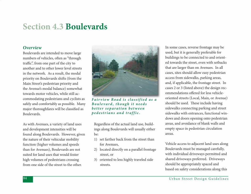
Ur b a n S t r e e t D e s i g n G u i d e l i n e s84
OverviewBoulevards are intended to move large numbers of vehicles, oft en as “through traffi c”, from one part of the city to another and to other lower level streets in the network. As a result, the modal priority on Boulevards shift s (from the Main Street’s pedestrian priority and the Avenue’s modal balance) somewhat towards motor vehicles, while still ac-commodating pedestrians and cyclists as safely and comfortably as possible. Many major thoroughfares will be classifi ed as Boulevards.
As with Avenues, a variety of land uses and development intensities will be found along Boulevards. However, given the nature of their vehicular mobility function (higher volumes and speeds than for Avenues), Boulevards are not suited for land uses that would foster high volumes of pedestrians crossing from one side of the street to the other.
Regardless of the actual land use, build-ings along Boulevards will usually either be:1) set farther back from the street than for Avenues,2) located directly on a parallel frontage street, or3) oriented to less highly traveled side streets.
In some cases, reverse frontage may be used, but it is generally preferable for buildings to be connected to and orient-ed towards the street, even with setbacks that are larger than on Avenues. In all cases, sites should allow easy pedestrian access from sidewalks, parking areas, and, if applicable, the frontage street. In cases 2 or 3 (listed above) the design rec-ommendations off ered for less vehicle-oriented streets (Local, Main, or Avenue) should be used. Th ese include having sidewalks connecting parking and street sidewalks with entrances, functional win-dows and doors opening onto pedestrian areas, and avoidance of blank walls and empty space in pedestrian circulation areas.
Vehicle access to adjacent land uses along Boulevards must be managed carefully, with individual driveways permitted and shared driveways preferred. Driveways should be appropriately spaced and based on safety considerations along this
Section 4.3 Boulevards
F a i r v i e w R o a d i s c l a s s i f i e d a s a B o u l e v a r d , t h o u g h i t n e e d s b e t t e r s e p a r a t i o n b e t w e e n p e d e s t r i a n s a n d t r a f f i c .
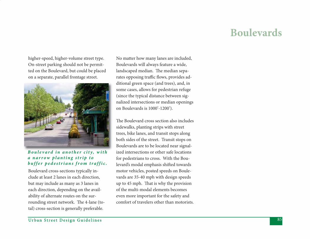
85Ur b a n S t r e e t D e s i g n G u i d e l i n e sUr b a n S t r e e t D e s i g n G u i d e l i n e s
higher-speed, higher-volume street type. On-street parking should not be permit-ted on the Boulevard, but could be placed on a separate, parallel frontage street.
Boulevard cross-sections typically in-clude at least 2 lanes in each direction, but may include as many as 3 lanes in each direction, depending on the avail-ability of alternate routes on the sur-rounding street network. Th e 4-lane (to-tal) cross-section is generally preferable.
No matter how many lanes are included, Boulevards will always feature a wide, landscaped median. Th e median sepa-rates opposing traffi c fl ows, provides ad-ditional green space (and trees), and, in some cases, allows for pedestrian refuge (since the typical distance between sig-nalized intersections or median openings on Boulevards is 1000’-1200’).
Th e Boulevard cross section also includes sidewalks, planting strips with street trees, bike lanes, and transit stops along both sides of the street. Transit stops on Boulevards are to be located near signal-ized intersections or other safe locations for pedestrians to cross. With the Bou-levard’s modal emphasis shift ed towards motor vehicles, posted speeds on Boule-vards are 35-40 mph with design speeds up to 45 mph. Th at is why the provision of the multi-modal elements becomes even more important for the safety and comfort of travelers other than motorists.
Boulevards
B o u l e v a r d i n a n o t h e r c i t y, w i t h a n a r r o w p l a n t i n g s t r i p t o b u f f e r p e d e s t r i a n s f r o m t r a f f i c .
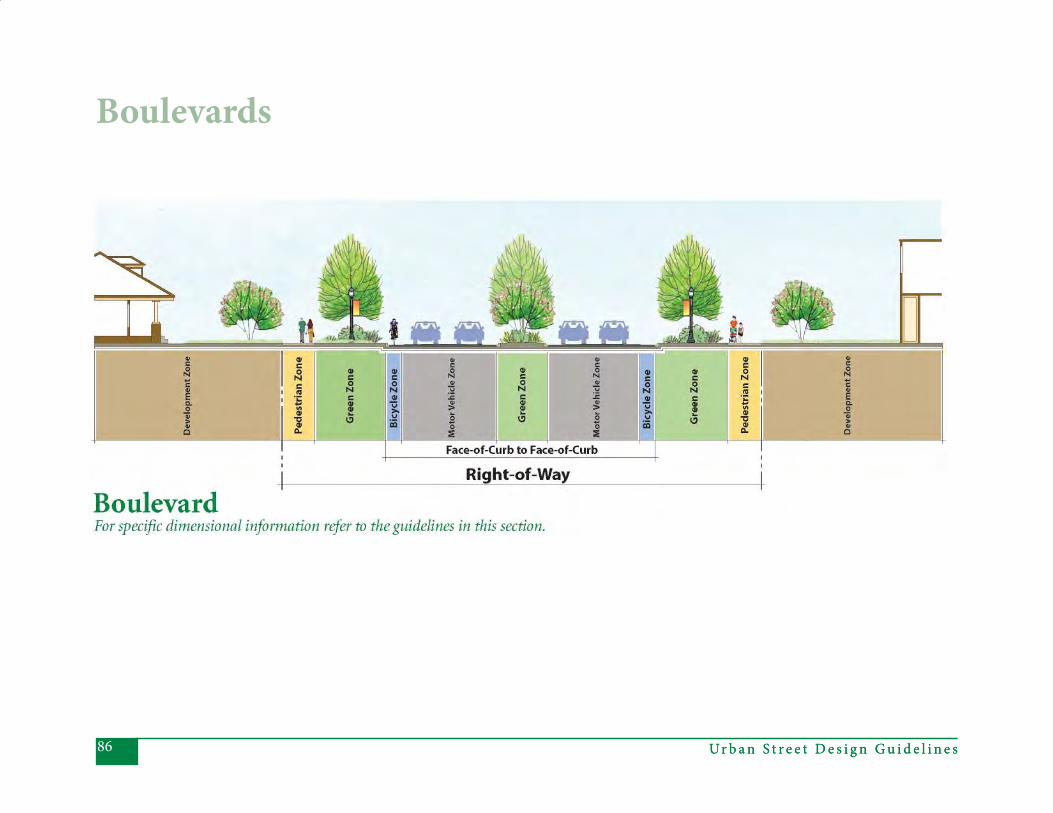
Ur b a n S t r e e t D e s i g n G u i d e l i n e s86 Ur b a n S t r e e t D e s i g n G u i d e l i n e s
Boulevards
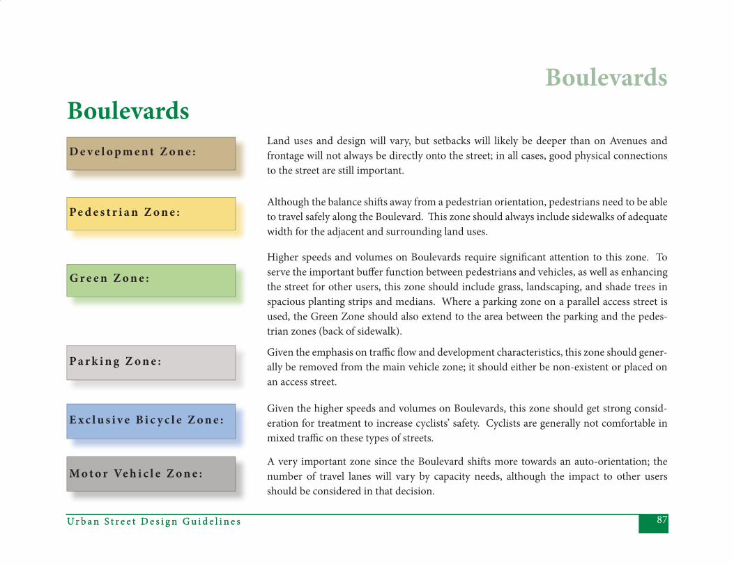
87Ur b a n S t r e e t D e s i g n G u i d e l i n e sUr b a n S t r e e t D e s i g n G u i d e l i n e s
Boulevards
A very important zone since the Boulevard shift s more towards an auto-orientation; the number of travel lanes will vary by capacity needs, although the impact to other users should be considered in that decision.
BoulevardsLand uses and design will vary, but setbacks will likely be deeper than on Avenues and frontage will not always be directly onto the street; in all cases, good physical connections to the street are still important.
Although the balance shift s away from a pedestrian orientation, pedestrians need to be able to travel safely along the Boulevard. Th is zone should always include sidewalks of adequate width for the adjacent and surrounding land uses.
Higher speeds and volumes on Boulevards require signifi cant attention to this zone. To serve the important buff er function between pedestrians and vehicles, as well as enhancing the street for other users, this zone should include grass, landscaping, and shade trees in spacious planting strips and medians. Where a parking zone on a parallel access street is used, the Green Zone should also extend to the area between the parking and the pedes-trian zones (back of sidewalk).
Given the emphasis on traffi c fl ow and development characteristics, this zone should gener-ally be removed from the main vehicle zone; it should either be non-existent or placed on an access street.
Given the higher speeds and volumes on Boulevards, this zone should get strong consid-eration for treatment to increase cyclists’ safety. Cyclists are generally not comfortable in mixed traffi c on these types of streets.
E x c l u s i v e B i c y c l e Z o n e :
D e v e l o p m e n t Z o n e :
Pe d e s t r i a n Z o n e :
G r e e n Z o n e :
P a r k i n g Z o n e :
M o t o r Ve h i c l e Z o n e :
Ur b a n S t r e e t D e s i g n G u i d e l i n e s88
Priority Elements:• Posted Speed – 35-40 mph. Speeds are higher than on an Avenue, refl ecting the Boulevard’s function of serving longer distance, intra-city traffi c fl ows.
• Design Speed – up to 45 mph. As with Avenues, design speed is slightly higher than posted speed, but not so high as to encourage speeding on these urban streets.
• Number of Th rough Lanes – Typically, 2 in each direction (4 total).
• Lane Width – 10 or 11’ lanes, in addi- tion to the concrete gutter where curb and gutter is present. 10’ inside lanes are particularly appropriate where the posted speed is 35 mph. Can also use 14’ wide outside lanes in some cases, as deemed by the Bicycle Plan.
• Medians – Should be provided on Boulevards. Typically, should be at
least 17’ wide to provide continuity be- tween the portions of median along the segment and at the intersection (where the 17’ width allows a minimal 6’ pedestrian refuge and an 11’ left - turn lane, if necessary). In constrained situations, the median can be narrower along a street segment, but never less than 6’ wide, since it is also to be used for pedestrian refuge.
• Median Planting – All medians should be landscaped. Landscaping should include trees, where possible given sight distance. At specifi ed mid-block crossing points, medians should be paved in a material that facilitates pedestrian use. Where pedestrian refuges are provided, plants should be no higher than 30 inches and tree limbs should fall no lower than 6’ to provide a “visibility zone” for pedestri- ans and motorists.
• Bicycle Accommodations – Bike lanes are desirable to allow cyclists to oper- ate in the higher speed Boulevard envi- ronment. Th ey are especially impor- tant when needed to complete or con- tinue a bicycle network or when there are few other options for network con- tinuity. Bicycle lanes should be striped and a minimum of 4’ wide. In most circumstances, 5’ lanes are preferred and, under certain conditions, 6’ lanes are preferred. Wide outside lanes (14’) may also be considered under con- strained conditions.
• Sidewalks – Although the characteris- tics of a Boulevard suggest that it is less pedestrian-oriented than either a Main Street or an Avenue, pedestrian activity is expected and encouraged along Boulevards. Th e higher speed, higher volume traffi c characteristics make sidewalks a required element. Side- walks should be a minimum of 6’
Boulevards

89Ur b a n S t r e e t D e s i g n G u i d e l i n e s
unobstructed width, except in highly constrained situations, where 5’ unob- structed width may be allowed.
• Planting Strips – Since Boulevards typically will have higher speeds, high- er volumes, and wider cross-sections, good separation between vehicular and pedestrian traffi c is desirable. Planting strips should be at least 8’ between curb and sidewalk, to allow for grass and large maturing trees. Sight distance should be considered in the location and spacing of trees within the planting strip. Depend- ing on factors such as street curvature, locations of driveways, land use con- text, and planting strip width, a mix of species, tree sizes, or diff erent spac- ing may be necessary to maintain minimal sight distances for vehicles entering the street.
• Curb and Gutter – Boulevards are urban locations, and should always
have curb and gutter. A minimum 2’0” curb and gutter should be used on the outside lane, but 1’6’’ is allowable on inside, median lanes.
• Lighting – Street lighting is to be pro- vided. Separate, decorative pedestrian- scale lighting should also be provided when necessitated by adjacent land uses or the existence of mid-block crossings, bus stops, or other facili- ties where pedestrian activity is likely to occur. Where it is provided, pe- destrian lighting should be suffi cient to illuminate the sidewalk, as well as to provide for pedestrian visibility and safety from crime. Pedestrian light- ing should be placed so that light is not obscured by branches and leaves.
• Block Length – Typical distance be- tween signalized intersections or me- dian openings on Boulevards is 1000’- 1200’ (approximately ¼ mile). It may be allowable or even desirable to pro-
vide more closely spaced side streets (to ensure a well-connected grid of streets off of the Boulevard), but median openings should not typically be provided at these more closely spaced locations. In some cases, direc- tional crossovers may be used to re- duce the number or frequency of median openings and signalized inter- sections. Th ese should be used spar- ingly and no more frequently spaced than 1000’-1200’.
Ur b a n S t r e e t D e s i g n G u i d e l i n e s90
Other Elements to Consider• Pedestrian Refuge - Th e median will typically provide for pedestrian refuge. Where the median serves as a pedes- trian refuge at specifi ed focal points, such as mid-block crossings, it should be paved in a material that facilitates pedestrian use.
• On-Street Parking - Should be sepa- rated from the travel lanes and pro- vided along a separate, parallel facility (frontage street). At those locations, curb extensions, matching the park- ing width, should be provided. Parallel parking lanes should ideally be 7’ wide. Angled parking may also be allowable since the parking is removed to the frontage street.
• Double Tree Rows – Allowable, for aes- thetics, if right-of-way is available.
• Driveways – Driveways are to be ex- pected in typical Boulevard land uses,
and are acceptable. In cases where adjacent land uses will result in high levels of ingress/egress, consider the use of frontage roads to minimize im- pact on through lanes.
• Bus Stops/Bus Zones – Preferred locations are generally at cross streets and high traffi c generators, although other locations are allowable. Pedes- trian enhancements should be in- cluded at all locations and may, in- some cases, include mid-block cross- ings and pedestrian refuges.
• Utilities – To preserve sidewalk capacity for pedestrians, maintain a clear zone per ADA requirements, and allow larger trees and other aesthetic treatments, utilities should be placed underground, wherever possible. Ev- ery attempt should be made, even with underground placement, to avoid or minimize confl icts with street trees. If underground placement is not pos-
sible, the preferred locations to con- sider for poles are at the back of the right-of-way or in the planting strip. In no circumstance should poles be placed in the sidewalk and, as with underground placement, every attempt should be made to avoid or minimize confl icts with street trees. Utility poles should be consolidated where possible, with redundant poles removed in ret- rofi t situations. • Mid-Block Pedestrian Crossings – Should typically be avoided on Bou- levards, due to the higher speeds. However, may be allowable in rare situations where the nearest signal- ized intersection is 600’ or more from an adjacent land use that is likely to create high pedestrian demand or at very heavy volume bus stops. When provided, crossings should include
high visibility markings and appro-priate signage. Hawk signals, curb extensions, and a pedestrian refuge
Boulevards
91Ur b a n S t r e e t D e s i g n G u i d e l i n e s
should also be strongly considered. See CDOT’s Mid-Block Crossing Policy for more information on safe crossings.
• Traffi c Calming – Many traffi c calm- ing tools are inappropriate on Bou- levards, given the Boulevard’s higher volume, higher speed function. How- ever, some forms of traffi c calming, such as street-side landscaping treat- ments or changes in horizontal align- ment, are allowable if necessary to maintain desired speeds (see CDOT’s Traffi c Calming Report for more infor- mation). Superelevation should be avoided or at least minimized.
Boulevards
Inappropriate Elements:• Sidewalk Amenity Zone – Typically not necessary, because the planting strip provides aesthetic enhancement and separation between pedestrians
and vehicles, which are operating at relatively high speeds.
• Shoulder – Inappropriate in an ur- ban Boulevard setting.
• Curb Extensions – Inappropriate on Boulevards, because they present a safety issue on these higher speed and higher volume streets. Further, curb extensions are typically used with on- street parking, which is not allowed on Boulevards. In the case where a front- age street is provided, the frontage street should have curb extensions, with the width matching the parking lane (typically 7’ wide).
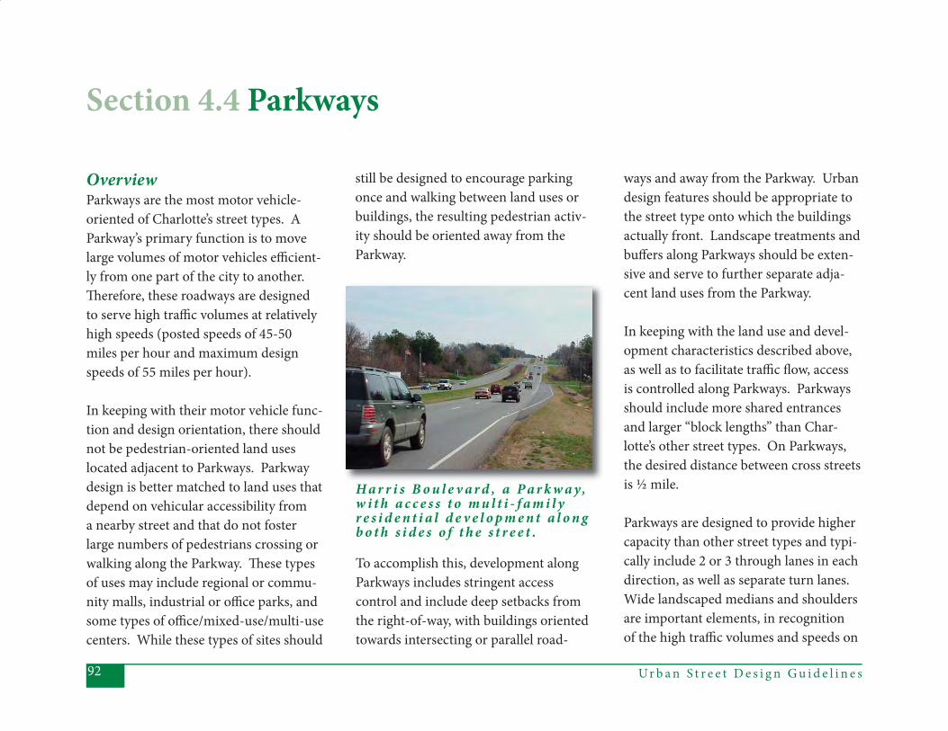
Ur b a n S t r e e t D e s i g n G u i d e l i n e s92
OverviewParkways are the most motor vehicle-oriented of Charlotte’s street types. A Parkway’s primary function is to move large volumes of motor vehicles effi cient-ly from one part of the city to another. Th erefore, these roadways are designed to serve high traffi c volumes at relatively high speeds (posted speeds of 45-50 miles per hour and maximum design speeds of 55 miles per hour).
In keeping with their motor vehicle func-tion and design orientation, there should not be pedestrian-oriented land uses located adjacent to Parkways. Parkway design is better matched to land uses that depend on vehicular accessibility from a nearby street and that do not foster large numbers of pedestrians crossing or walking along the Parkway. Th ese types of uses may include regional or commu-nity malls, industrial or offi ce parks, and some types of offi ce/mixed-use/multi-use centers. While these types of sites should
still be designed to encourage parking once and walking between land uses or buildings, the resulting pedestrian activ-ity should be oriented away from the Parkway.
To accomplish this, development along Parkways includes stringent access control and include deep setbacks from the right-of-way, with buildings oriented towards intersecting or parallel road-
Section 4.4 Parkways
H a r r i s B o u l e v a r d , a P a r k w a y, w i t h a c c e s s t o m u l t i - f a m i l y r e s i d e n t i a l d e v e l o p m e n t a l o n g b o t h s i d e s o f t h e s t r e e t .
ways and away from the Parkway. Urban design features should be appropriate to the street type onto which the buildings actually front. Landscape treatments and buff ers along Parkways should be exten-sive and serve to further separate adja-cent land uses from the Parkway.
In keeping with the land use and devel-opment characteristics described above, as well as to facilitate traffi c fl ow, access is controlled along Parkways. Parkways should include more shared entrances and larger “block lengths” than Char-lotte’s other street types. On Parkways, the desired distance between cross streets is ½ mile.
Parkways are designed to provide higher capacity than other street types and typi-cally include 2 or 3 through lanes in each direction, as well as separate turn lanes. Wide landscaped medians and shoulders are important elements, in recognition of the high traffi c volumes and speeds on

93Ur b a n S t r e e t D e s i g n G u i d e l i n e sUr b a n S t r e e t D e s i g n G u i d e l i n e s
Parkways
Parkways. In addition, this is the only street type for which a “clear zone” is explicitly specifi ed to enhance motorist safety.
Since the immediate Parkway environ-ment is not well suited for pedestrian and bicycle traffi c, pathways for these travelers should be provided on separate facilities. Ideally, bicycle and pedestrian facilities should be located on nearby, parallel streets. Th ose streets would provide most of the access to develop-ment adjacent to the Parkway, as well as a continual, connected network for cyclists and other travelers. If such routes are not available or feasible nearby, then provision should be made for cyclists and pedestrians to travel as far from the roadway and clear zone as possible.
Parkways are most appropriate for ex-press bus or other limited-stop routes. When transit stops are provided, they should be located off the Parkway, ei-ther within adjacent developments or on cross-streets. If off -Parkway stops are not possible, bus pull-outs should be provided to remove buses from the high speed travel lanes.
An o t h e r s e c t i o n o f H a r r i s B o u l e v a r d , a p p r o a c h i n g c o m m e r c i a l l a n d u s e s . T h i s s e c t i o n h a s m o r e a c c e s s c o n t r o l .
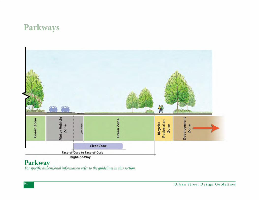
Ur b a n S t r e e t D e s i g n G u i d e l i n e s94 Ur b a n S t r e e t D e s i g n G u i d e l i n e s
Parkways
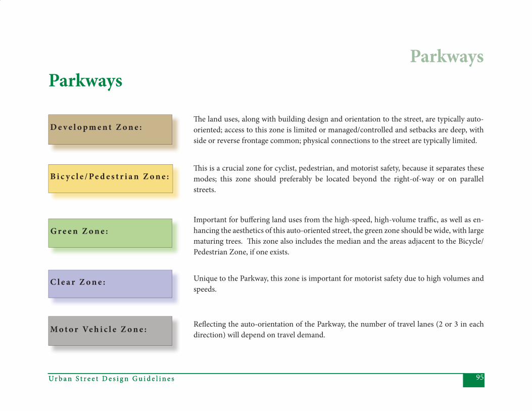
95Ur b a n S t r e e t D e s i g n G u i d e l i n e sUr b a n S t r e e t D e s i g n G u i d e l i n e s
D e v e l o p m e n t Z o n e :
Parkways
Th e land uses, along with building design and orientation to the street, are typically auto-oriented; access to this zone is limited or managed/controlled and setbacks are deep, with side or reverse frontage common; physical connections to the street are typically limited.
Th is is a crucial zone for cyclist, pedestrian, and motorist safety, because it separates these modes; this zone should preferably be located beyond the right-of-way or on parallel streets.
B i c y c l e / Pe d e s t r i a n Z o n e :
G r e e n Z o n e :Important for buff ering land uses from the high-speed, high-volume traffi c, as well as en-hancing the aesthetics of this auto-oriented street, the green zone should be wide, with large maturing trees. Th is zone also includes the median and the areas adjacent to the Bicycle/Pedestrian Zone, if one exists.
Unique to the Parkway, this zone is important for motorist safety due to high volumes and speeds.
C l e a r Z o n e :
M o t o r Ve h i c l e Z o n e : Refl ecting the auto-orientation of the Parkway, the number of travel lanes (2 or 3 in each direction) will depend on travel demand.
Parkways
Ur b a n S t r e e t D e s i g n G u i d e l i n e s96
Priority Elements:• Posted Speed – 45-50 mph, refl ect- ing that this is a roadway used for high-speed, intra-city connectivity.
• Top Design Speed – Up to 55 mph.
• Number of Th rough Lanes – 2 in each direction (4 total) or 3 in each direc- tion (6 total), as determined by capac- ity analysis.
• Lane Width – Typically 12’ lanes (not including concrete gutter, if curb and gutter exists). In constrained situations, minimum 11’ lanes are acceptable.
• Medians – Should be provided on Parkways. At least 20’ wide is prefer- able, to provide continuity between the portions of median along the segment and at intersections (where the 20’ width allows a minimal 9’ pedestrian refuge and an 11’ left -turn lane). If
the right-of-way is severely con- strained, the median can be narrower away from intersections (not less than 17’ wide), but will need to transition to the wider dimension as it approaches an intersection.
• Median Planting – All medians should be landscaped. Landscaping should include trees, where possible given sight distance and an adequate clear zone.
• Shoulder – A shoulder should always be provided on a Parkway. Th e shoul- der should ideally be 10’ wide, but a minimum of 8’ wide may be allowable in constrained situations.
• Sidewalks – Th e preferred pedestrian treatment along Parkways is a separate, parallel facility. Th is should be shared with bicycles if no preferred alternative for bicycle accommodations is possible (in which case, a 10’ minimum
unobstructed path is required and there must be very limited access along the Parkway). If it is not possible to construct a parallel facility and if right-of-way is available, sidewalks (minimum 5’ wide unobstructed) may be provided for pedestrian network connectivity, particularly to connect transit stops to nearby pedes trian generating land uses. Th is side walk should be located as far as possible from travel lanes to provide a safer and more comfortable pedestrian environment.
• Planting Strips – If there is no side- walk, the entire right-of-way should be treated as a planting strip. Trees are desirable, but should be located be- yond the 25’ clear zone (from the edge of the travel lane). In cases where a sidewalk is provided, a planting strip with grass and low ground cover should be included to separate pedestrians from the high-speed
Parkways
97Ur b a n S t r e e t D e s i g n G u i d e l i n e s
vehicular traffi c. To provide adequate separation, the planting strip should be a minimum of 15’ between curb (if curb exists) or shoulder and the side- walk.
• Lighting – Street lighting is desirable on Parkways. In cases where pedes- trian facilities exist along Parkways, it is generally expected that the regular street lighting should also provide for adequate pedestrian lighting. How- ever, where the pedestrian facility is removed from the Parkway (as a sepa- rate path, for example) and at bus stops, separate pedestrian lighting should be considered, depending on ambient light, location of street light- ing, and visibility/safety. Pedestrian lighting should be placed so that il- lumination is not obscured by branch- es and leaves.
• Block Length (distance between cross- streets) – Due to the function of
Parkways, it is generally desirable to limit access. Th erefore, the distance between cross-streets should ideally be at least ½ mile. Shorter “block lengths” are allowable only when existing inter- mediate streets cannot be closed, or when required by land parcel confi gu- ration.
Parkways
Ur b a n S t r e e t D e s i g n G u i d e l i n e s98
Other Elements to Consider• Curb and Gutter – Either curb and gutter or drainage swales are allow- able, though curb and gutter is atypi- cal, since a shoulder should always be provided. If curb and gutter is provid- ed, mountable curbs should be used.
• Bus Stops – If there are bus routes op- erating on Parkways, bus stops should be located off the roadway. If this is not feasible, bus pull-outs should be provided, so that the bus is not stop- ping in mixed traffi c. Bus stops should have sidewalks (minimum 5’ wide unobstructed) connecting to sur- rounding land uses, as well as pedes- trian scale lighting, if deemed neces- sary for safety.
• Utilities – Where they are neces- sary, poles should be located at back of right-of-way, beyond the 25’ clear zone (from edge of travel lane). In no cir- cumstance should utility poles be placed in sidewalks or bicycle paths.
Parkways
99Ur b a n S t r e e t D e s i g n G u i d e l i n e s
Inappropriate Elements:• Driveways – Inappropriate and unsafe on a Parkway. Should only be provid- ed when no other access is possible to a property or when a driveway is pre- existing. Every eff ort should be made to provide alternate access in order to eliminate existing driveways.
• Bicycle Accommodations – Bicycle lanes are typically inappropriate on Parkways. In some cases, they may be allowable, but only when necessary for network connectivity. Bicycle routes on nearby, parallel streets (which are not Parkways) are prefer- able. In some cases, there could be a shared bicycle/pedestrian facility par- allel to the Parkway (in which case, a 10’ minimum unobstructed path is required and there must be very lim- ited access along the Parkway).
• Sidewalk Amenity Zone – Although
sidewalks may be provided in some cases (see above), a sidewalk amenity zone is inappropriate, due to the ve- hicular orientation of Parkways.
• On-Street Parking – Inappropri- ate, since the function of a Parkway is to move traffi c at higher volumes and speeds than any other street type.
• Curb Extensions – Inappropriate, since the function of a Parkway is to move traffi c at higher volumes and speeds than any other street type.
• Traffi c Calming – Inappropriate, since the function of a Parkway is to move traffi c at higher volumes and speeds than any other street type.
• Mid-block Pedestrian Crossings - Mid-block pedestrian crossings would be unsafe in the Parkway environ- ment, since the function of a Parkway
Parkways
is to move traffi c at higher volumes and speeds than any other street type. Further, the land use context of the Parkway is unlikely to create the need for mid-block crossings.
• Pedestrian Refuge – Pedestrians are typically not expected or encouraged on Parkways. Pedestrian refuges should not be provided along the segment, so as to not encourage mid- block pedestrian crossings.
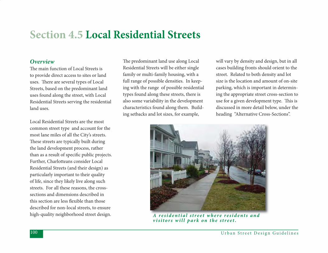
Ur b a n S t r e e t D e s i g n G u i d e l i n e s100
OverviewTh e main function of Local Streets is to provide direct access to sites or land uses. Th ere are several types of Local Streets, based on the predominant land uses found along the street, with Local Residential Streets serving the residential land uses.
Local Residential Streets are the most common street type and account for the most lane miles of all the City’s streets.Th ese streets are typically built during the land development process, rather than as a result of specifi c public projects. Further, Charlotteans consider Local Residential Streets (and their design) as particularly important to their quality of life, since they likely live along such streets. For all these reasons, the cross-sections and dimensions described in this section are less fl exible than those described for non-local streets, to ensure high-quality neighborhood street design.
Th e predominant land use along Local Residential Streets will be either single family or multi-family housing, with a full range of possible densities. In keep-ing with the range of possible residential types found along these streets, there is also some variability in the development characteristics found along them. Build-ing setbacks and lot sizes, for example,
will vary by density and design, but in all cases building fronts should orient to the street. Related to both density and lot size is the location and amount of on-site parking, which is important in determin-ing the appropriate street cross-section to use for a given development type. Th is is discussed in more detail below, under the heading “Alternative Cross-Sections”.
Section 4.5 Local Residential Streets
A r e s i d e n t i a l s t r e e t w h e r e r e s i d e n t s a n d v i s i t o r s w i l l p a r k o n t h e s t r e e t .

101Ur b a n S t r e e t D e s i g n G u i d e l i n e s
Because Local Residential Streets are intended to provide direct access to the residential land uses along them, indi-vidual driveways are the norm. However, in the case of higher-density, multi-fam-ily housing, shared driveways are encour-aged to help reduce confl icts between pe-destrians and turning vehicles, to reduce the number of and total space allotted to curb cuts (thereby allowing more space
Regardless of the applicable cross-sec-tion, there are several common ele-ments to all Local Residential Streets. Th ese streets are designed for low traffi c speeds and volumes since they are serv-ing mostly neighborhood traffi c, and a comfortable walking, cycling, and living environment is expected along them.
Local Residential Streets will have small blocks, which will provide both a high degree of connectivity for motorists, pe-destrians, and cyclists, as well as a form of traffi c calming for residents, through frequently spaced intersections. Th is is described in more detail in the Chapter 4 introduction, under the heading “Block Lengths for Local Streets.” Local Residen-tial Streets, therefore, will include built-in traffi c calming features (such as intersec-tions or other “slow points” every 300’-500’) along with continuous sidewalks, planting strips, and street trees, to en-hance safety, functionality, and aesthetic value for all users.
for on-street parking), and to increase potential green space.
Transit service is not typical on most local streets, but may be available, espe-cially as feeder or neighborhood circula-tor service. Th e location and spacing of bus stops, therefore, is highly variable on these streets.
Local Residential Streets
O n t h i s r e s i d e n t i a l s t r e e t i n My e r s P a r k , o n - s t r e e t p a r k i n g h a s b e e n l i m i t e d t o o n e s i d e .
At t h e s e d e n s i t i e s , o n - s t r e e t p a r k i n g s h o u l d b e p r o v i d e d o n b o t h s i d e s o f t h e s t r e e t .
Ur b a n S t r e e t D e s i g n G u i d e l i n e s102
Cross-Section AlternativesLocal Residential Streets will refl ect one of the following three cross-sections:
• Narrow (may be used under condi- tions described below)• Medium (the default)• Wide (must be used under condi- tions described below)
Selection of the appropriate cross-section depends primarily on the likely demand for on-street parking and the density of the street network. Th e general intent is to keep the curb-to-curb dimensions of Local Residential Streets as narrow as possible, while providing adequate width for emergency vehicles or for other vehicles to safely get around parked cars. In general, the more on-site parking provided, via longer driveways, rear or side loading garages, larger lots, shared parking, etc., the narrower the allowed cross-section.
Th e medium cross-section is used when it is likely that on-street parking will occur on both sides of the street with some frequency. Th e narrow cross-sec-tion is to be used only when it is likely that on-street parking will be relatively infrequent and likely to occur on only one side of the street at any given time, and the street network is well-connected. Th e wide cross-section applies where a high demand for on-street parking is likely. Th is cross-section includes a travel lane in each direction and parking on both sides of the street. Th is width will also allow emergency vehicle staging anywhere along the block.
Th e medium cross-section is the de-fault cross-section for Local Residen-tial Streets.
Th e “narrow” cross-section may be used if:
• net densities along the street are below 4 units per acre, • lots are at least 80’ wide, • garages or parking areas are side loaded, rear loaded, recessed, or lo- cated behind the residence, • there is more than one connection to the street (for redundant emer- gency access routes), and• there are alternative, parallel routes available.
OR, if:
• net densities along the street are 4-7 units per acre,• there is suffi cient shared parking to allow for three vehicles per unit on- site, • there is more than one connection to the street (for redundant emer- gency access routes),• there are alternative, parallel routes available, and• block length is a maximum of 650’.
Local Residential Streets
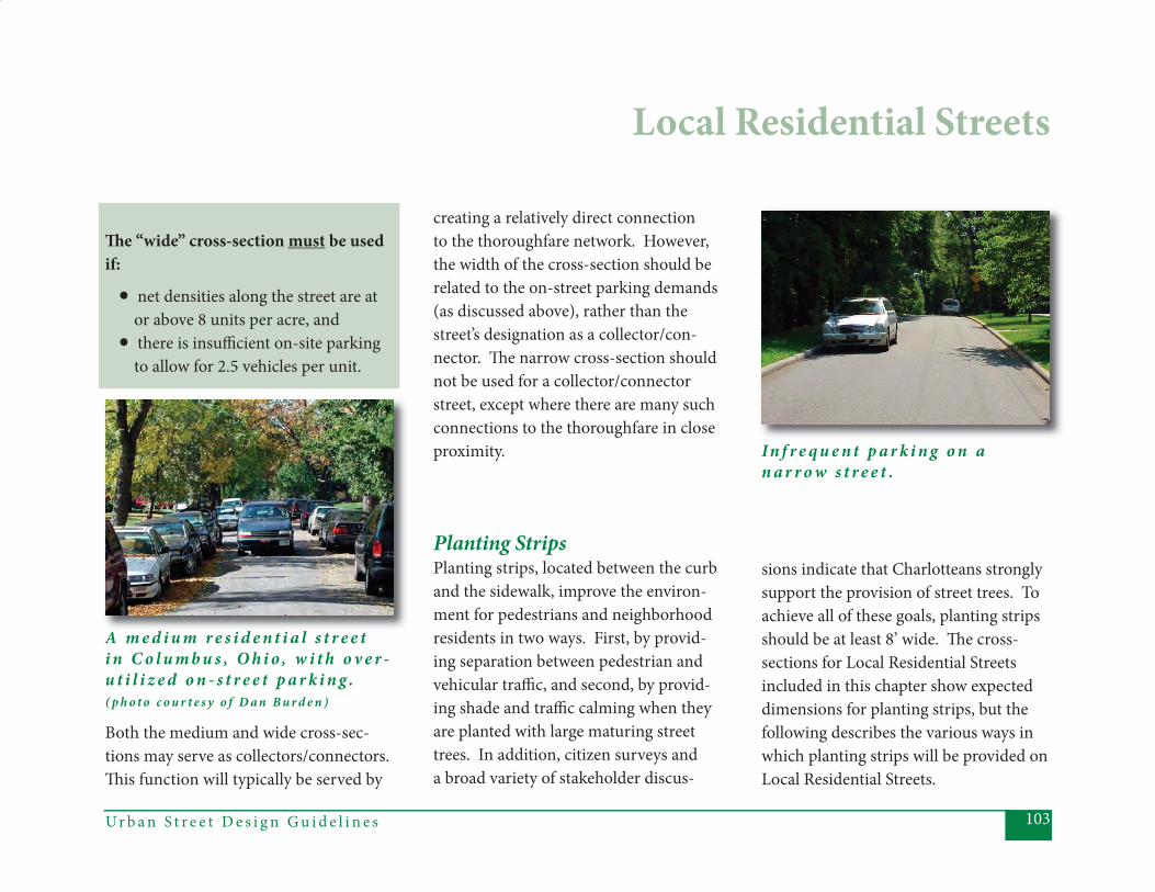
103Ur b a n S t r e e t D e s i g n G u i d e l i n e s
Th e “wide” cross-section must be used if:
• net densities along the street are at or above 8 units per acre, and• there is insuffi cient on-site parking to allow for 2.5 vehicles per unit.
Local Residential Streets
Both the medium and wide cross-sec-tions may serve as collectors/connectors. Th is function will typically be served by
A m e d i u m r e s i d e n t i a l s t r e e t i n C o l u m b u s , O h i o , w i t h o v e r -u t i l i z e d o n - s t r e e t p a r k i n g . ( p h o t o c o u r t e s y o f D a n B u r d e n )
In f r e q u e n t p a r k i n g o n a n a r r o w s t r e e t .
creating a relatively direct connection to the thoroughfare network. However, the width of the cross-section should be related to the on-street parking demands (as discussed above), rather than the street’s designation as a collector/con-nector. Th e narrow cross-section should not be used for a collector/connector street, except where there are many such connections to the thoroughfare in close proximity.
Planting Strips Planting strips, located between the curb and the sidewalk, improve the environ-ment for pedestrians and neighborhood residents in two ways. First, by provid-ing separation between pedestrian and vehicular traffi c, and second, by provid-ing shade and traffi c calming when they are planted with large maturing street trees. In addition, citizen surveys and a broad variety of stakeholder discus-
sions indicate that Charlotteans strongly support the provision of street trees. To achieve all of these goals, planting strips should be at least 8’ wide. Th e cross-sections for Local Residential Streets included in this chapter show expected dimensions for planting strips, but the following describes the various ways in which planting strips will be provided on Local Residential Streets.
Ur b a n S t r e e t D e s i g n G u i d e l i n e s104
Local Residential Streets
1. New Local Residential Streets, built through the private development process in subdivisions or greenfi elds:
• Th e “Narrow” street includes an 8’ planting strip planted with large ma-turing street trees.
• Th e “Medium” street includes an 8’ planting strip (preferred) planted with large maturing street trees, or a 6’ planting strip planted with medium maturing street trees*. Th e site de-veloper and staff will be expected to justify why they are not providing the 8’ planting strips. Th e 8’ width is par-ticularly recommended for entrance streets in new subdivisions and along any interior streets likely to carry the higher traffi c volumes.
*Approved species lists of appropriate street trees for 6’ and 8’ planting strips is provided by Landscape Manage-ment.
• Th e “Wide” street includes an 8’ plant-ing strip or an 8’ amenity zone, either of which should be planted with large maturing trees.
It may sometimes be allowable to “mean-der” the sidewalk for short distances (af-fecting planting strip width) to preserve existing trees (specifi cally, where large lot development allows the potential for signifi cant frontyard tree save and the ex-isting trees are in the vicinity of the side-walk location). Even in these cases, the planting strip must be a minimum of 4’ wide (or the sidewalk must go behind the preserved trees), to maintain an adequate buff er between pedestrians and vehicles, and the distance of the “meander” should be as short as possible.
2. Retrofi t projects built by the City on existing Local Streets: where deemed reasonable, the project design team is expected to provide an 8’ planting strip and incorporate large maturing street
trees (with trees to be planted at the time the project is completed). Th e team will document any reasons for deviating from the preferred width. Reasons might include: a) avoiding interference with existing
stands of mature trees, b) steep slopes, c) retaining walls, d) location of existing houses, e) location of existing utilities, or f) other issues related to existing houses
and yards.
3. Infi ll development projects fronting along existing Local Streets: as with #2 above, the expectation is to provide, where possible, an 8’ planting strip and large maturing street trees (with trees to be planted at the time the project is com-pleted). Any deviation should be docu-mented in much the same way as for City projects, with the exception that items d and f would not apply for new construc-tion (infi ll development projects would
105Ur b a n S t r e e t D e s i g n G u i d e l i n e s
Local Residential Streets
typically be removing existing structures, allowing the appropriate planting strip and sidewalk widths to be constructed in most cases).
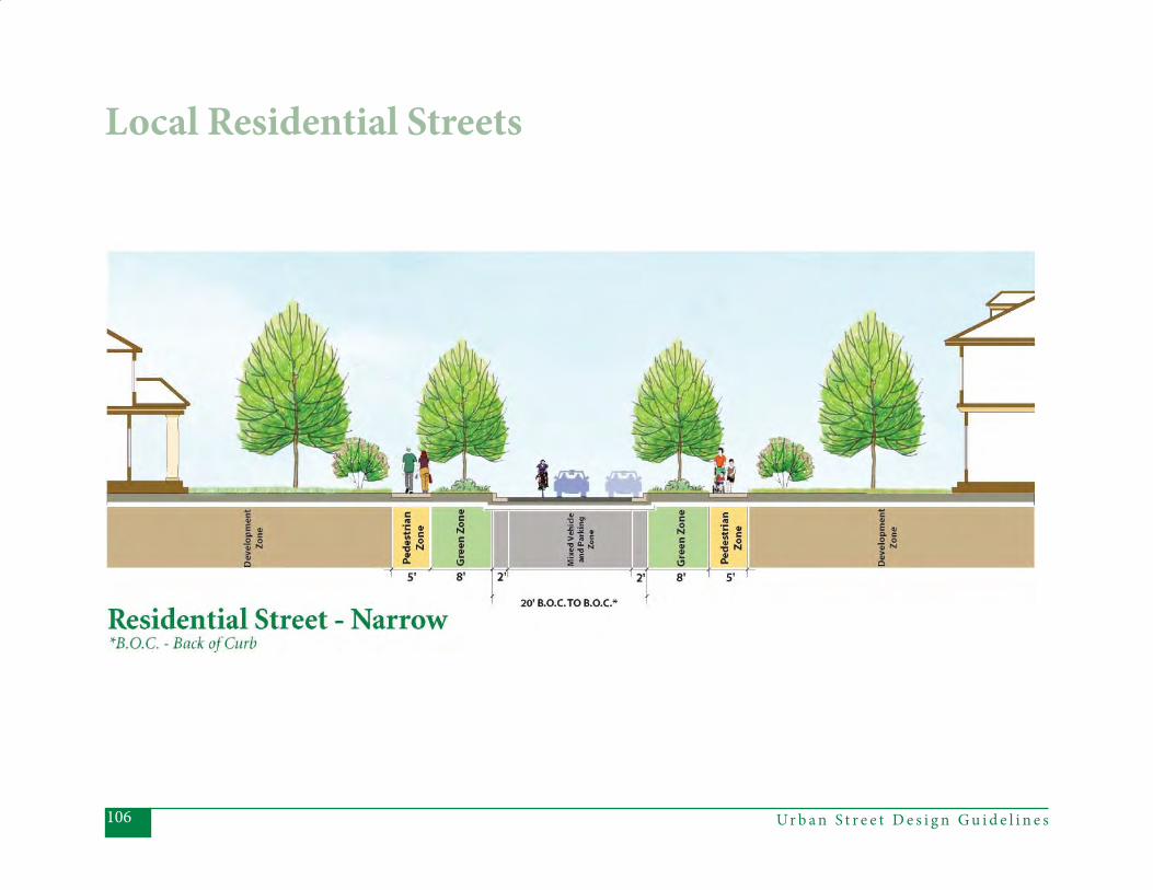
Ur b a n S t r e e t D e s i g n G u i d e l i n e s106
Local Residential Streets
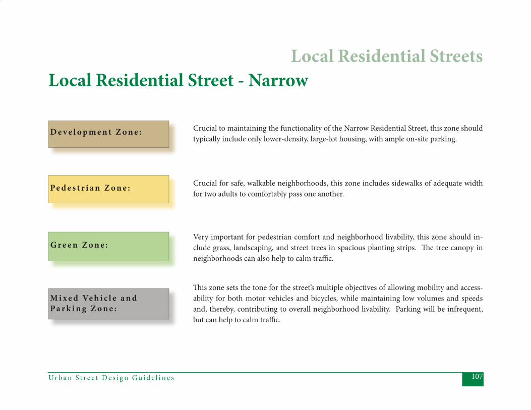
107Ur b a n S t r e e t D e s i g n G u i d e l i n e s
D e v e l o p m e n t Z o n e :
Local Residential Street - Narrow
Crucial to maintaining the functionality of the Narrow Residential Street, this zone should typically include only lower-density, large-lot housing, with ample on-site parking.
Crucial for safe, walkable neighborhoods, this zone includes sidewalks of adequate width for two adults to comfortably pass one another.
Pe d e s t r i a n Z o n e :
G r e e n Z o n e :Very important for pedestrian comfort and neighborhood livability, this zone should in-clude grass, landscaping, and street trees in spacious planting strips. Th e tree canopy in neighborhoods can also help to calm traffi c.
M i x e d Ve h i c l e a n d P a r k i n g Z o n e :
Th is zone sets the tone for the street’s multiple objectives of allowing mobility and access-ability for both motor vehicles and bicycles, while maintaining low volumes and speeds and, thereby, contributing to overall neighborhood livability. Parking will be infrequent, but can help to calm traffi c.
Local Residential Streets
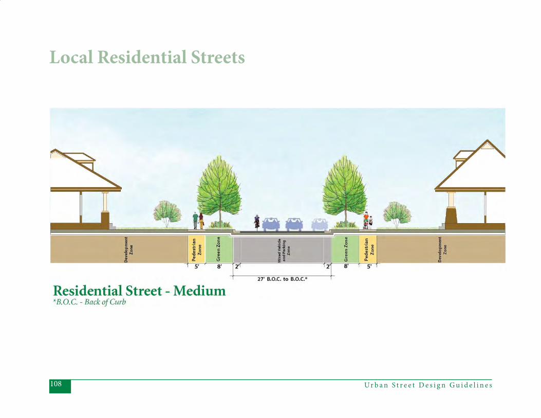
Ur b a n S t r e e t D e s i g n G u i d e l i n e s108
Local Residential Streets
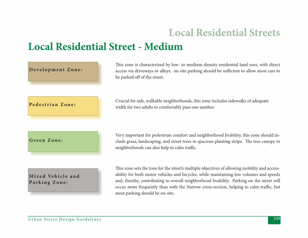
109Ur b a n S t r e e t D e s i g n G u i d e l i n e s
D e v e l o p m e n t Z o n e :
Local Residential Street - MediumTh is zone is characterized by low- to medium-density residential land uses, with direct access via driveways or alleys; on-site parking should be suffi cient to allow most cars to be parked off of the street.
Crucial for safe, walkable neighborhoods, this zone includes sidewalks of adequate width for two adults to comfortably pass one another.Pe d e s t r i a n Z o n e :
G r e e n Z o n e :Very important for pedestrian comfort and neighborhood livability, this zone should in-clude grass, landscaping, and street trees in spacious planting strips. Th e tree canopy in neighborhoods can also help to calm traffi c.
M i x e d Ve h i c l e a n d P a r k i n g Z o n e :
Th is zone sets the tone for the street’s multiple objectives of allowing mobility and access-ability for both motor vehicles and bicycles, while maintaining low volumes and speeds and, thereby, contributing to overall neighborhood livability. Parking on the street will occur more frequently than with the Narrow cross-section, helping to calm traffi c, but most parking should be on-site.
Local Residential Streets
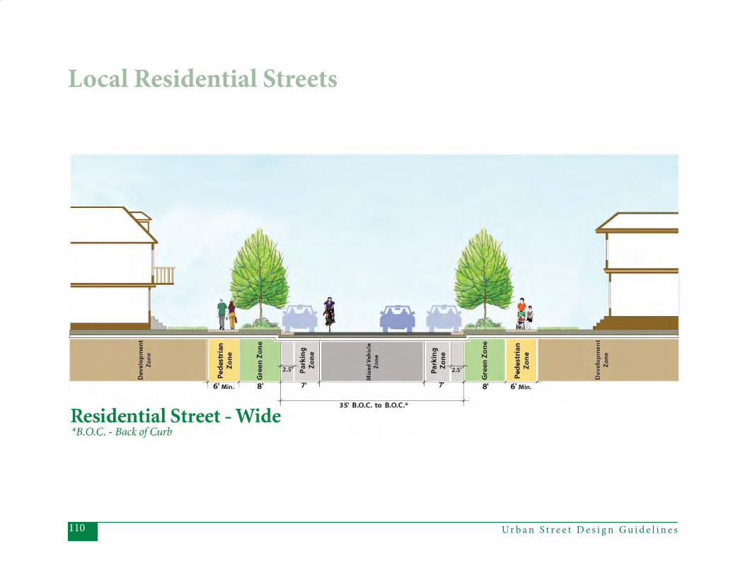
Ur b a n S t r e e t D e s i g n G u i d e l i n e s110
Local Residential Streets
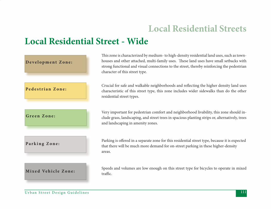
111Ur b a n S t r e e t D e s i g n G u i d e l i n e s
D e v e l o p m e n t Z o n e :
Local Residential Street - WideTh is zone is characterized by medium- to high-density residential land uses, such as town-houses and other attached, multi-family uses. Th ese land uses have small setbacks with strong functional and visual connections to the street, thereby reinforcing the pedestrian character of this street type.
Crucial for safe and walkable neighborhoods and refl ecting the higher density land uses characteristic of this street type, this zone includes wider sidewalks than do the other residential street types.
Pe d e s t r i a n Z o n e :
G r e e n Z o n e :Very important for pedestrian comfort and neighborhood livability, this zone should in-clude grass, landscaping, and street trees in spacious planting strips or, alternatively, trees and landscaping in amenity zones.
M i x e d Ve h i c l e Z o n e : Speeds and volumes are low enough on this street type for bicycles to operate in mixed traffi c.
Parking is off ered in a separate zone for this residential street type, because it is expected that there will be much more demand for on-street parking in these higher-density areas.
P a r k i n g Z o n e :
Local Residential Streets
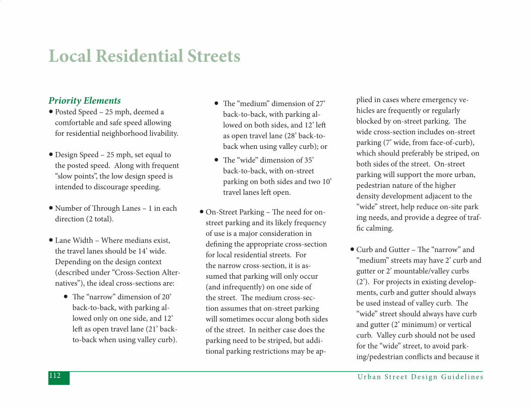
Ur b a n S t r e e t D e s i g n G u i d e l i n e s112
Priority Elements• Posted Speed – 25 mph, deemed a comfortable and safe speed allowing for residential neighborhood livability.
• Design Speed – 25 mph, set equal to the posted speed. Along with frequent “slow points”, the low design speed is intended to discourage speeding.
• Number of Th rough Lanes – 1 in each direction (2 total).
• Lane Width – Where medians exist, the travel lanes should be 14’ wide. Depending on the design context (described under “Cross-Section Alter- natives”), the ideal cross-sections are:
• Th e “narrow” dimension of 20’ back-to-back, with parking al- lowed only on one side, and 12’ left as open travel lane (21’ back- to-back when using valley curb).
• Th e “medium” dimension of 27’ back-to-back, with parking al- lowed on both sides, and 12’ left as open travel lane (28’ back-to- back when using valley curb); or
• Th e “wide” dimension of 35’ back-to-back, with on-street parking on both sides and two 10’ travel lanes left open.
• On-Street Parking – Th e need for on- street parking and its likely frequency of use is a major consideration in defi ning the appropriate cross-section for local residential streets. For the narrow cross-section, it is as- sumed that parking will only occur (and infrequently) on one side of the street. Th e medium cross-sec- tion assumes that on-street parking will sometimes occur along both sides of the street. In neither case does the parking need to be striped, but addi- tional parking restrictions may be ap-
plied in cases where emergency ve- hicles are frequently or regularly blocked by on-street parking. Th e wide cross-section includes on-street parking (7’ wide, from face-of-curb), which should preferably be striped, on both sides of the street. On-street parking will support the more urban, pedestrian nature of the higher density development adjacent to the “wide” street, help reduce on-site park ing needs, and provide a degree of traf- fi c calming.
• Curb and Gutter – Th e “narrow” and “medium” streets may have 2’ curb and gutter or 2’ mountable/valley curbs (2’). For projects in existing develop- ments, curb and gutter should always be used instead of valley curb. Th e “wide” street should always have curb and gutter (2’ minimum) or vertical curb. Valley curb should not be used for the “wide” street, to avoid park- ing/pedestrian confl icts and because it
Local Residential Streets
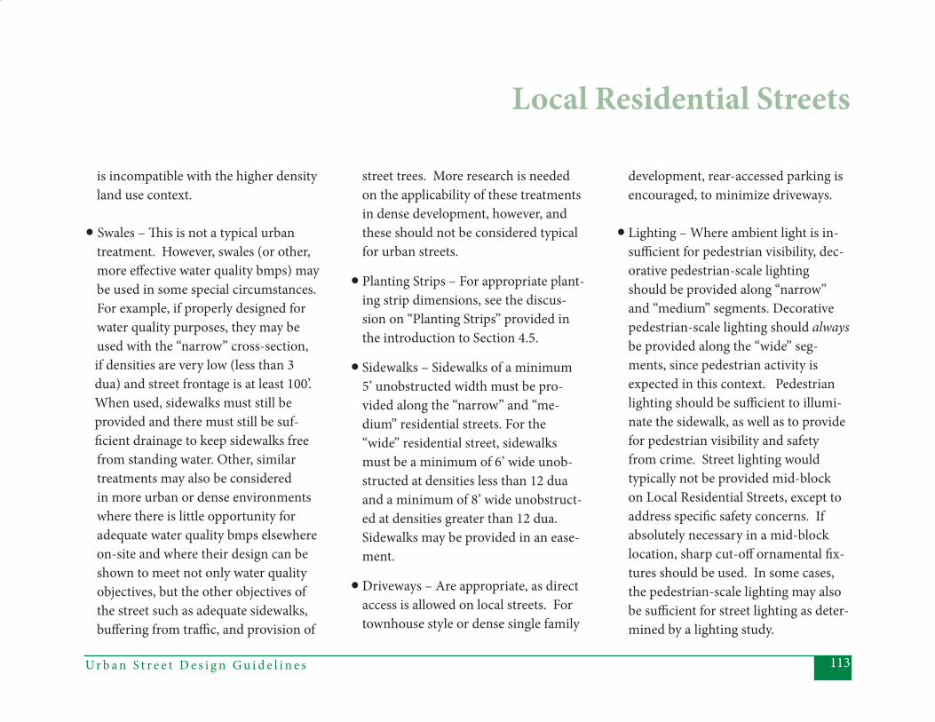
113Ur b a n S t r e e t D e s i g n G u i d e l i n e s
is incompatible with the higher density land use context. • Swales – Th is is not a typical urban
treatment. However, swales (or other, more eff ective water quality bmps) may be used in some special circumstances. For example, if properly designed for water quality purposes, they may be used with the “narrow” cross-section,
if densities are very low (less than 3 dua) and street frontage is at least 100’. When used, sidewalks must still be provided and there must still be suf- fi cient drainage to keep sidewalks free
from standing water. Other, similar treatments may also be considered in more urban or dense environments where there is little opportunity for adequate water quality bmps elsewhere on-site and where their design can be shown to meet not only water quality objectives, but the other objectives of the street such as adequate sidewalks, buff ering from traffi c, and provision of
street trees. More research is needed on the applicability of these treatments in dense development, however, and these should not be considered typical for urban streets.
• Planting Strips – For appropriate plant-ing strip dimensions, see the discus-sion on “Planting Strips” provided in the introduction to Section 4.5.
• Sidewalks – Sidewalks of a minimum 5’ unobstructed width must be pro- vided along the “narrow” and “me- dium” residential streets. For the “wide” residential street, sidewalks must be a minimum of 6’ wide unob- structed at densities less than 12 dua and a minimum of 8’ wide unobstruct- ed at densities greater than 12 dua. Sidewalks may be provided in an ease- ment.
• Driveways – Are appropriate, as direct access is allowed on local streets. For townhouse style or dense single family
development, rear-accessed parking is encouraged, to minimize driveways. • Lighting – Where ambient light is in- suffi cient for pedestrian visibility, dec- orative pedestrian-scale lighting should be provided along “narrow” and “medium” segments. Decorative pedestrian-scale lighting should always be provided along the “wide” seg- ments, since pedestrian activity is expected in this context. Pedestrian lighting should be suffi cient to illumi- nate the sidewalk, as well as to provide for pedestrian visibility and safety from crime. Street lighting would typically not be provided mid-block on Local Residential Streets, except to address specifi c safety concerns. If absolutely necessary in a mid-block location, sharp cut-off ornamental fi x- tures should be used. In some cases, the pedestrian-scale lighting may also be suffi cient for street lighting as deter- mined by a lighting study.
Local Residential Streets
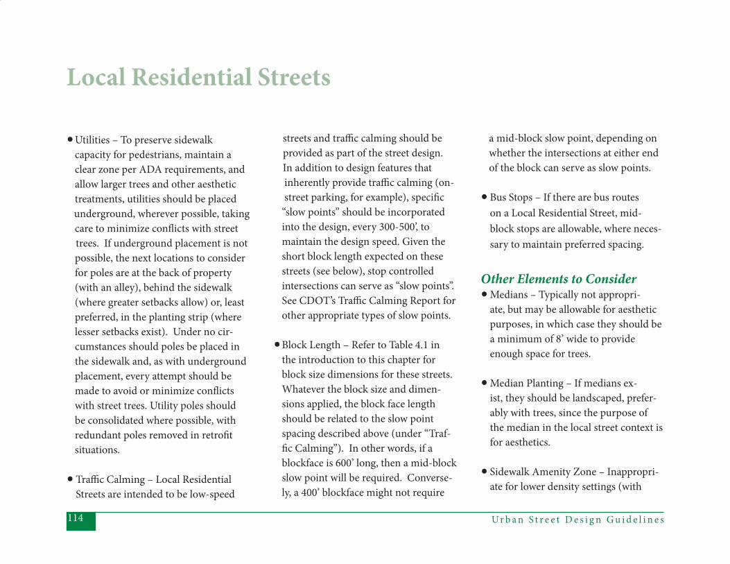
Ur b a n S t r e e t D e s i g n G u i d e l i n e s114
• Utilities – To preserve sidewalk capacity for pedestrians, maintain a clear zone per ADA requirements, and allow larger trees and other aesthetic treatments, utilities should be placed underground, wherever possible, taking
care to minimize confl icts with street trees. If underground placement is not possible, the next locations to consider for poles are at the back of property (with an alley), behind the sidewalk (where greater setbacks allow) or, least preferred, in the planting strip (where lesser setbacks exist). Under no cir-cumstances should poles be placed in the sidewalk and, as with underground placement, every attempt should be made to avoid or minimize confl icts with street trees. Utility poles should be consolidated where possible, with redundant poles removed in retrofi t situations.
• Traffi c Calming – Local Residential Streets are intended to be low-speed
streets and traffi c calming should be provided as part of the street design.
In addition to design features that inherently provide traffi c calming (on- street parking, for example), specifi c “slow points” should be incorporated into the design, every 300-500’, to maintain the design speed. Given the short block length expected on these streets (see below), stop controlled intersections can serve as “slow points”. See CDOT’s Traffi c Calming Report for other appropriate types of slow points.
• Block Length – Refer to Table 4.1 in the introduction to this chapter for block size dimensions for these streets. Whatever the block size and dimen-sions applied, the block face length should be related to the slow point spacing described above (under “Traf-fi c Calming”). In other words, if a blockface is 600’ long, then a mid-block slow point will be required. Converse-ly, a 400’ blockface might not require
a mid-block slow point, depending on whether the intersections at either end of the block can serve as slow points.
• Bus Stops – If there are bus routes on a Local Residential Street, mid- block stops are allowable, where neces- sary to maintain preferred spacing.
Other Elements to Consider• Medians – Typically not appropri- ate, but may be allowable for aesthetic purposes, in which case they should be a minimum of 8’ wide to provide enough space for trees.
• Median Planting – If medians ex- ist, they should be landscaped, prefer- ably with trees, since the purpose of the median in the local street context is for aesthetics.
• Sidewalk Amenity Zone – Inappropri- ate for lower density settings (with
Local Residential Streets

115Ur b a n S t r e e t D e s i g n G u i d e l i n e s
the “narrow” and “medium” cross- section), because planting strips are the preferred treatment to provide separa- tion between pedestrian and vehicu- lar traffi c. Where the “wide” cross- section is used, the amenity zone is still not required, but should be considered in locations where on-street parking parallels high pedestrian activity zones, especially if the residential land use includes ground fl oor retail (though these uses could be more ap- propriately categorized as Local Offi ce/ Commercial Streets). In such cases, the amenity zone could either substi- tute for or alternate with the planting strip. An amenity zone may also be appropriate in constrained situations where an 8’ planting strip is impossible – as described under “Planting Strips” – and a narrower amenity zone will further enhance the sidewalk (by pro- viding more space for pedestrians).
Inappropriate Elements:• Pedestrian Refuge – Not necessary on a 2-lane local street, particularly when other traffi c calming devices are provided to maintain the relatively low speeds.
• Curb Extensions – Typically inap- propriate, except where used for traffi c calming purposes. See Chapter 5 for a discussion of curb extensions at intersections.
• Shoulder – Inappropriate for a local street in an urban or suburban setting.
• Bicycle Lanes – Typically not neces- sary on local streets, because bicycles can share the lanes with low-volume, low-speed traffi c. Local streets may be designated as bicycle routes, particu- larly in locations close to Parkways, where a nearby, alternative route is desirable.
Local Residential Streets
• Mid-Block Pedestrian Crossings – Typically unnecessary on a 2 lane street with low volumes and speeds. May be considered under certain circumstanc- es, as outlined in CDOT’s Mid-Block Crossing Policy.
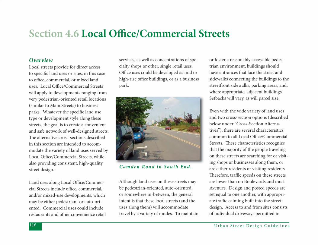
Ur b a n S t r e e t D e s i g n G u i d e l i n e s116
OverviewLocal streets provide for direct access to specifi c land uses or sites, in this case to offi ce, commercial, or mixed land uses. Local Offi ce/Commercial Streets will apply to developments ranging from very pedestrian-oriented retail locations (similar to Main Streets) to business parks. Whatever the specifi c land use type or development style along these streets, the goal is to create a convenient and safe network of well-designed streets. Th e alternative cross-sections described in this section are intended to accom-modate the variety of land uses served by Local Offi ce/Commercial Streets, while also providing consistent, high-quality street design.
Land uses along Local Offi ce/Commer-cial Streets include offi ce, commercial, and/or mixed-use developments, which may be either pedestrian- or auto-ori-ented. Commercial uses could include restaurants and other convenience retail
services, as well as concentrations of spe-cialty shops or other, single retail uses. Offi ce uses could be developed as mid or high-rise offi ce buildings, or as a business park.
Although land uses on these streets may be pedestrian-oriented, auto-oriented, or somewhere in-between, the general intent is that these local streets (and the uses along them) will accommodate travel by a variety of modes. To maintain
or foster a reasonably accessible pedes-trian environment, buildings should have entrances that face the street and sidewalks connecting the buildings to the streetfront sidewalks, parking areas, and, where appropriate, adjacent buildings. Setbacks will vary, as will parcel size.
Even with the wide variety of land uses and two cross-section options (described below under “Cross-Section Alterna-tives”), there are several characteristics common to all Local Offi ce/Commercial Streets. Th ese characteristics recognize that the majority of the people traveling on these streets are searching for or visit-ing shops or businesses along them, or are either residents or visiting residents. Th erefore, traffi c speeds on these streets are lower than on Boulevards and most Avenues. Design and posted speeds are set equal to one another, with appropri-ate traffi c calming built into the street design. Access to and from sites consists of individual driveways permitted in
Section 4.6 Local Offi ce/Commercial Streets
C a m d e n R o a d i n S o u t h E n d .
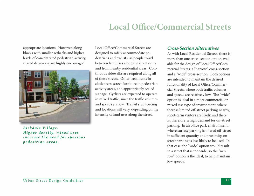
117Ur b a n S t r e e t D e s i g n G u i d e l i n e s
appropriate locations. However, along blocks with smaller setbacks and higher levels of concentrated pedestrian activity, shared driveways are highly encouraged.
Local Offi ce/Commercial Streets
Local Offi ce/Commercial Streets are designed to safely accommodate pe-destrians and cyclists, as people travel between land uses along the street or to and from nearby residential areas. Con-tinuous sidewalks are required along all of these streets. Other treatments in-clude trees, street furniture in pedestrian activity areas, and appropriately scaled signage. Cyclists are expected to operate in mixed traffi c, since the traffi c volumes and speeds are low. Transit stop spacing and locations will vary, depending on the intensity of land uses along the street.
Cross-Section AlternativesAs with Local Residential Streets, there is more than one cross-section option avail-able for the design of Local Offi ce/Com-mercial Streets: a “narrow” cross-section and a “wide” cross-section. Both options are intended to maintain the desired functionality of Local Offi ce/Commer-cial Streets, where both traffi c volumes and speeds are relatively low. Th e “wide” option is ideal in a more commercial or mixed-use type of environment, where there is limited off -street parking nearby, short-term visitors are likely, and there is, therefore, a high demand for on-street parking. In an offi ce park environment, where surface parking is off ered off -street in suffi cient quantity and proximity, on-street parking is less likely to be used. In that case, the “wide” option would result in a street that is too wide, so the “nar-row” option is the ideal, to help maintain low speeds.
B i r k d a l e Vi l l a g e .Hi g h e r d e n s i t y, m i x e d u s e si n c r e a s e t h e n e e d f o r s p a c i o u s p e d e s t r i a n a r e a s .
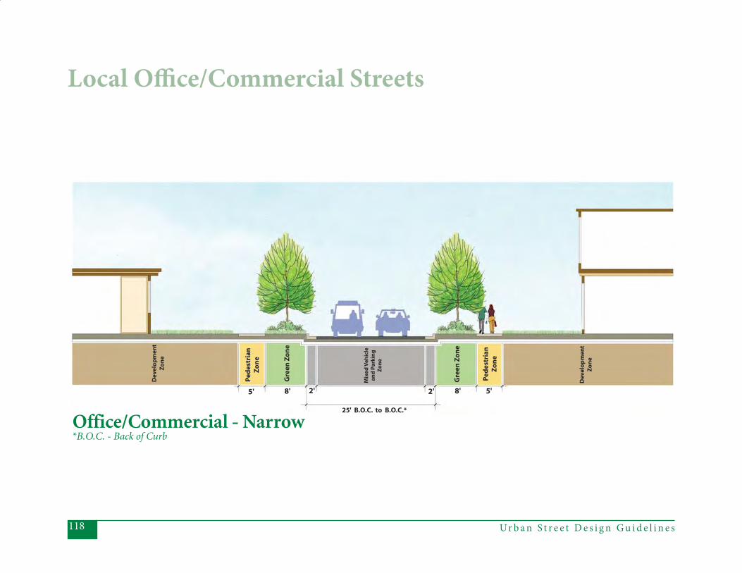
Ur b a n S t r e e t D e s i g n G u i d e l i n e s118
Local Offi ce/Commercial Streets
25' B.O.C. to B.O.C.*
2' 2'5' 8' 8' 5'
Gre
enZ
on
e
Gre
enZ
on
e
Ped
estr
ian
Zo
ne
Ped
estr
ian
Zo
ne
Mix
edV
ehic
lean
dP
ark
ing
Zo
ne
Dev
elo
pm
ent
Zo
ne
Dev
elo
pm
ent
Zo
ne
Office/Commercial - Narrow*B.O.C. - Back of Curb
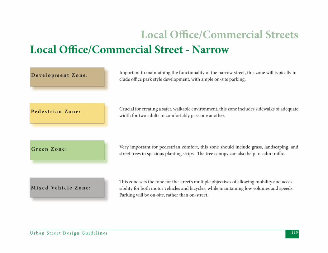
119Ur b a n S t r e e t D e s i g n G u i d e l i n e s
D e v e l o p m e n t Z o n e :
Local Offi ce/Commercial Street - Narrow
Important to maintaining the functionality of the narrow street, this zone will typically in-clude offi ce park style development, with ample on-site parking.
Crucial for creating a safer, walkable environment, this zone includes sidewalks of adequate width for two adults to comfortably pass one another.
Pe d e s t r i a n Z o n e :
G r e e n Z o n e : Very important for pedestrian comfort, this zone should include grass, landscaping, and street trees in spacious planting strips. Th e tree canopy can also help to calm traffi c.
M i x e d Ve h i c l e Z o n e :Th is zone sets the tone for the street’s multiple objectives of allowing mobility and acces-sibility for both motor vehicles and bicycles, while maintaining low volumes and speeds. Parking will be on-site, rather than on-street.
Local Offi ce/Commercial Streets
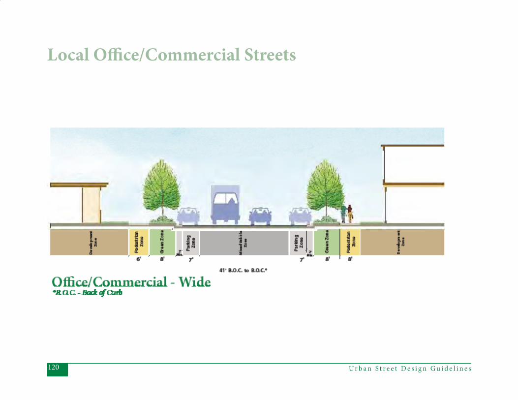
Ur b a n S t r e e t D e s i g n G u i d e l i n e s120
Local Offi ce/Commercial Streets
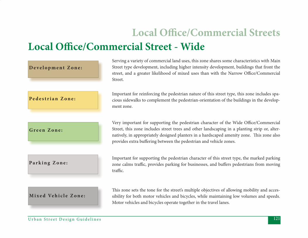
121Ur b a n S t r e e t D e s i g n G u i d e l i n e s
D e v e l o p m e n t Z o n e :
Local Offi ce/Commercial Street - WideServing a variety of commercial land uses, this zone shares some characteristics with Main Street type development, including higher intensity development, buildings that front the street, and a greater likelihood of mixed uses than with the Narrow Offi ce/Commercial Street.
Important for reinforcing the pedestrian nature of this street type, this zone includes spa-cious sidewalks to complement the pedestrian-orientation of the buildings in the develop-ment zone.
Pe d e s t r i a n Z o n e :
G r e e n Z o n e :Very important for supporting the pedestrian character of the Wide Offi ce/Commercial Street, this zone includes street trees and other landscaping in a planting strip or, alter-natively, in appropriately designed planters in a hardscaped amenity zone. Th is zone also provides extra buff ering between the pedestrian and vehicle zones.
M i x e d Ve h i c l e Z o n e :Th is zone sets the tone for the street’s multiple objectives of allowing mobility and acces-sibility for both motor vehicles and bicycles, while maintaining low volumes and speeds. Motor vehicles and bicycles operate together in the travel lanes.
Important for supporting the pedestrian character of this street type, the marked parking zone calms traffi c, provides parking for businesses, and buff ers pedestrians from moving traffi c.
P a r k i n g Z o n e :
Local Offi ce/Commercial Streets
Ur b a n S t r e e t D e s i g n G u i d e l i n e s122
Priority Elements:• Posted Speed – 25 mph, deemed a comfortable and safe speed for local streets in urban environments.
• Design Speed – 25 mph, set equal to the posted speed. Along with frequent “slow points”, the low design speed is intended to discourage speeding.
• Number of Th rough Lanes – 1 in each direction (2 total).
• Lane Width – Should provide at least 12’ lanes to accommodate maneuvering delivery trucks and other large vehicles. Th e cross-section should refl ect one of two options:
• A “wide” dimension of 41’ back- to-back, with two 13’ travel lanes and on-street parking (7’ wide) on both sides; or
• A “narrow” dimension of 25’ back-to-back, with two 12’ travel lanes (including gutter) and no on-street parking.
• On-Street Parking – Parallel parking should typically be provided on both sides of the street (7’ wide), preferably striped, where the wide cross-section is employed. In that case, on-street parking will help reduce off -street parking needs and provide a degree of traffi c calming. On-street parking should not be provided where the narrow cross-section is employed.
• Curb and Gutter – Should always have curb and gutter or vertical curb. If curb and gutter is provided, 2’0’’ is the minimum.
• Planting Strips – Planting strips im- prove the pedestrian environment by providing separation between pedes-
trian and vehicular traffi c, as well as shade when they are planted with large maturing trees. To achieve these goals, planting strips should be at least 8’ wide. Where on-street parking is likely to be most intensely used (direct- ly adjacent to commercial or mixed-use buildings, for example), consider alter- nating recessed on-street parking with the planting strip and paved amenity zones with trees in appropriately de- signed planters.
• Sidewalks – Pedestrian activity is to be expected, encouraged, and accommo- dated on these streets. In the higher density commercial or mixed-use context, where on-street parking and the wider cross-section are used, sidewalks should provide a minimum of 8’ unobstructed width. In the lower density offi ce setting, without on-street parking (and where the narrow cross- section is used), provide a 5’ minimum unobstructed width.
Local Offi ce/Commercial Streets
123Ur b a n S t r e e t D e s i g n G u i d e l i n e s
• Bus Stops – If there are bus routes on a Local Offi ce/Commercial Street mid- block stops are allowable, where neces- sary to maintain preferred spacing.
• Driveways – Are appropriate, to allow frequent access to adjacent land uses. However, in higher density locations, shared driveways are encouraged. • Lighting – Street lighting is to be provided. Separate pedestrian lighting should always be provided along the “wide” cross-section and should be considered anywhere higher levels of pedestrian activity are anticipated, either because of adjacent or surrounding commercial activity or because the area provides a major pedestrian route or pathway between land uses or to parking areas. Where
provided, pedestrian lighting should be suffi cient to illuminate the sidewalk, as well as to provide for pedestrian visibil- ity and safety from crime. In some
cases, the pedestrian-scale lighting may also be suffi cient for street lighting, as determined through a lighting analysis.
• Utilities – To preserve sidewalk capacity for pedestrians, maintain a clear zone per ADA requirements, and allow larger trees and other aesthetic treatments, utilities should be placed underground, taking care to minimize confl icts with street trees. If under- ground placement is not possible, the next locations to consider for poles are at the back of property (with an alley), behind the sidewalk (where greater setbacks allow) or, least preferred, in the planting strip (where lesser setbacks exist). In no circumstance should poles be placed in the sidewalk and, as with underground placement, every attempt should be made to avoid or minimize confl icts with street trees. Utility poles should be consolidated where possible, with redundant poles removed in retro- fi t situations.
• Traffi c Calming – Local Offi ce/Com- mercial Streets are intended to be low speed streets and traffi c calming should be provided as part of the street design. In addition to design features
that inherently provide traffi c calm- ing (on-street parking, for example), specifi c “slow points” should be incor- porated into the design, every 300’-500’, to maintain the design speed. See CDOT’s Traffi c Calming Report for
appropriate types of slow points.
• Block Length – To provide appropri- ate scale and connectivity options for all modes, the block lengths described
in Table 4.1, located in the introduction to this chapter, should be applied.
Local Offi ce/Commercial Streets
Ur b a n S t r e e t D e s i g n G u i d e l i n e s124
Other Elements to Consider• Sidewalk Amenity Zone – Not re- quired, but may be allowable in the higher density commercial or mixed- use context, where on-street parking and the wider cross-section are used. In such cases, the amenity zone could either substitute for or alternate with the planting strip (unless the planting strip is alternated with recessed on- street parking, in which case, the ame- nity zone is unnecessary).
• Medians – Typically not appropriate, but may be allowable for aesthetic purposes, in which case they should be a minimum of 8’ wide. In addition, lane widths should be increased to 14’, exclusive of parking lanes.
• Median Planting – If medians exist, they should be landscaped, preferably with trees, since the purpose of the median in the local street context is for aesthetics.
Local Offi ce/Commercial Streets
125Ur b a n S t r e e t D e s i g n G u i d e l i n e s
Inappropriate Elements:• Pedestrian Refuge – Not necessary on a 2-lane local street, particularly when other traffi c calming devices are pro- vided.
• Curb Extensions – Typically not pro- vided on segments, unless they are to be used for traffi c calming.
• Bicycle Lanes – Typically not neces- sary on local streets, because bicycles can share the lanes with lower-volume, low-speed traffi c. Local streets may, however, be designated as bicycle routes, particularly in locations close to Parkways, where a nearby, alternative route is desirable.
• Shoulder – Inappropriate for a local street in an urban or suburban setting.
• Mid-Block Pedestrian Crossings – Typically unnecessary on a 2-lane street with low volumes and speeds.
May be considered under certain circumstances, as outlined in CDOT’s Mid-Block Crossing Policy.
Local Offi ce/Commercial Streets
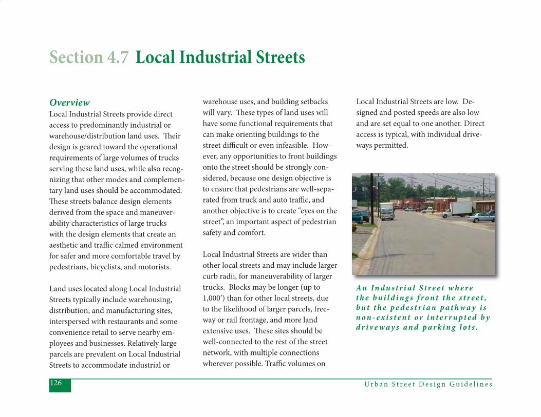
Ur b a n S t r e e t D e s i g n G u i d e l i n e s126
OverviewLocal Industrial Streets provide direct access to predominantly industrial or warehouse/distribution land uses. Th eir design is geared toward the operational requirements of large volumes of trucks serving these land uses, while also recog-nizing that other modes and complemen-tary land uses should be accommodated. Th ese streets balance design elements derived from the space and maneuver-ability characteristics of large trucks with the design elements that create an aesthetic and traffi c calmed environment for safer and more comfortable travel by pedestrians, bicyclists, and motorists.
Land uses located along Local Industrial Streets typically include warehousing, distribution, and manufacturing sites, interspersed with restaurants and some convenience retail to serve nearby em-ployees and businesses. Relatively large parcels are prevalent on Local Industrial Streets to accommodate industrial or
warehouse uses, and building setbacks will vary. Th ese types of land uses will have some functional requirements that can make orienting buildings to the street diffi cult or even infeasible. How-ever, any opportunities to front buildings onto the street should be strongly con-sidered, because one design objective is to ensure that pedestrians are well-sepa-rated from truck and auto traffi c, and another objective is to create “eyes on the street”, an important aspect of pedestrian safety and comfort.
Local Industrial Streets are wider than other local streets and may include larger curb radii, for maneuverability of larger trucks. Blocks may be longer (up to 1,000’) than for other local streets, due to the likelihood of larger parcels, free-way or rail frontage, and more land extensive uses. Th ese sites should be well-connected to the rest of the street network, with multiple connections wherever possible. Traffi c volumes on
Local Industrial Streets are low. De-signed and posted speeds are also low and are set equal to one another. Direct access is typical, with individual drive-ways permitted.
Section 4.7 Local Industrial Streets
A n In d u s t r i a l S t r e e t w h e r e t h e b u i l d i n g s f r o n t t h e s t r e e t , b u t t h e p e d e s t r i a n p a t h w a y i s n o n - e x i s t e n t o r i n t e r r u p t e d b y d r i v e w a y s a n d p a r k i n g l o t s .
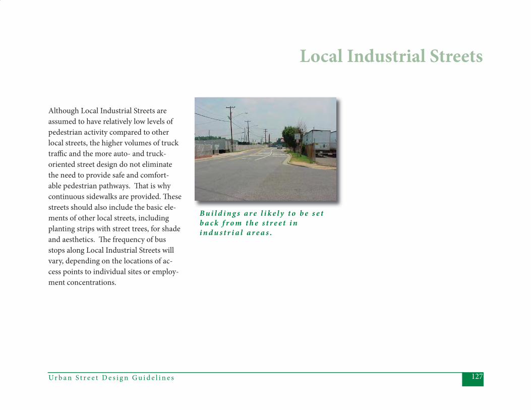
127Ur b a n S t r e e t D e s i g n G u i d e l i n e s
Although Local Industrial Streets are assumed to have relatively low levels of pedestrian activity compared to other local streets, the higher volumes of truck traffi c and the more auto- and truck-oriented street design do not eliminate the need to provide safe and comfort-able pedestrian pathways. Th at is why continuous sidewalks are provided. Th ese streets should also include the basic ele-ments of other local streets, including planting strips with street trees, for shade and aesthetics. Th e frequency of bus stops along Local Industrial Streets will vary, depending on the locations of ac-cess points to individual sites or employ-ment concentrations.
Local Industrial Streets
B u i l d i n g s a r e l i k e l y t o b e s e t b a c k f r o m t h e s t r e e t i n i n d u s t r i a l a r e a s .
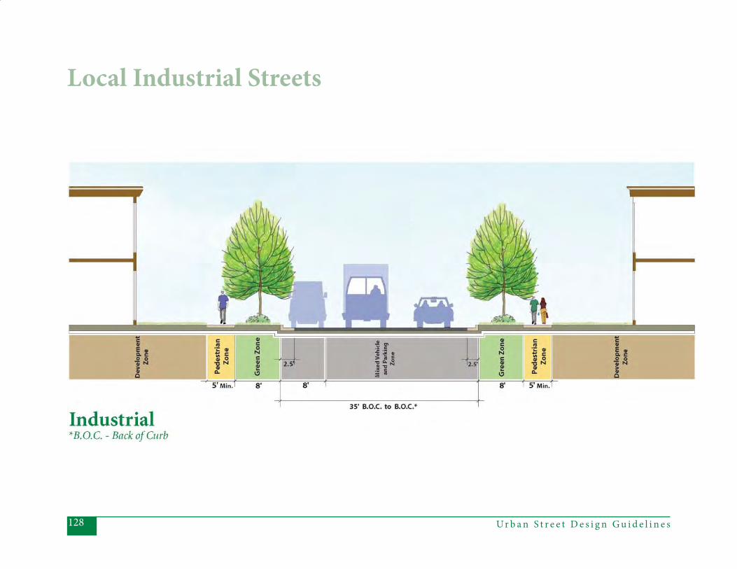
Ur b a n S t r e e t D e s i g n G u i d e l i n e s128
Local Industrial Streets
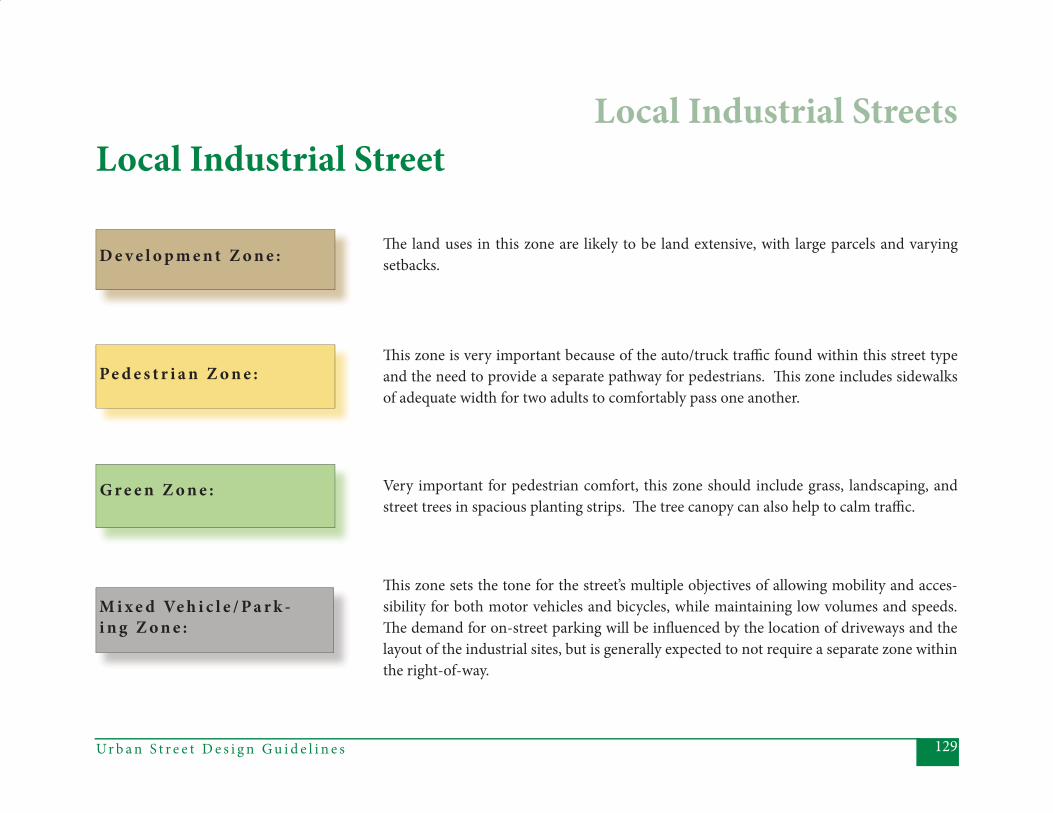
129Ur b a n S t r e e t D e s i g n G u i d e l i n e s
D e v e l o p m e n t Z o n e :
Local Industrial Street
Th e land uses in this zone are likely to be land extensive, with large parcels and varying setbacks.
Th is zone is very important because of the auto/truck traffi c found within this street type and the need to provide a separate pathway for pedestrians. Th is zone includes sidewalks of adequate width for two adults to comfortably pass one another.
Pe d e s t r i a n Z o n e :
G r e e n Z o n e : Very important for pedestrian comfort, this zone should include grass, landscaping, and street trees in spacious planting strips. Th e tree canopy can also help to calm traffi c.
M i x e d Ve h i c l e / P a r k -i n g Z o n e :
Th is zone sets the tone for the street’s multiple objectives of allowing mobility and acces-sibility for both motor vehicles and bicycles, while maintaining low volumes and speeds. Th e demand for on-street parking will be infl uenced by the location of driveways and the layout of the industrial sites, but is generally expected to not require a separate zone within the right-of-way.
Local Industrial Streets
Ur b a n S t r e e t D e s i g n G u i d e l i n e s130
Priority Elements• Posted Speed - 25 mph, deemed a safe and comfortable speed in urban environments.
• Design Speed - 25 mph, set equal to the posted speed. Low design speed is intended to discourage speeding.
• Number of Th rough Lanes - 1 in each direction (2 total).
• Lane Width - Typically, 12 ft lanes. Th e cross section is 35’ back-of-curb to back-of-curb, to allow two 12’ travel
lanes, 8’ for parking (on one side), and 2’ gutter (on the side not used for park ing). Th ese dimensions should provide for adequate maneuverability and potential staging of vehicles, if necessary.
• On-Street Parking - Parallel parking typically provided on one side of the street, 8’ wide (including the gutter),
to allow for truck parking when neces-sary.
• Curb and Gutter-Should always have 2’6” curb and gutter.
• Planting Strips - Th e planting strip provides separation between pedes-trian and vehicular traffi c and room for
healthy tree growth, an important con- sideration in a low density, industrial environment. Should be a minimum of 8’ to support large maturing trees.
• Sidewalks - Pedestrian traffi c may be lighter in industrial locations than in other local street contexts, but pedes- trians must still be accommodated, particularly given the truck traffi c on
the Local Industrial Street. Minimum 5’ unobstructed width sidewalks must be provided.
• Driveways - Appropriate, as direct ac- cess is expected.
• Lighting - Street lighting typically pro- vided along segments only where nec- essary for safety. Separate pedestrian lighting is typically not necessary.
• Utilities - To preserve sidewalk capacity for pedestrians, maintain a clear zone per ADA requirements, and allow larger trees and other aesthetic treatments, utilities should be placed underground, taking care to minimize
confl icts with street trees. If under-ground placement is not possible, the next locations to consider for poles are behind the sidewalk or in the planting strip. In no circumstance should poles be placed in the sidewalk and, as with underground placement, every attempt should be made to avoid or minimize confl icts with street trees. Utility poles should be consolidated where pos-sible, with redundant poles removed in retrofi t situations.
• Block Length - As described in Table 4.1, in the introduction to this chapter, Local Industrial Streets’ block lengths may be longer than other local street types, due to the land uses and typi-cally larger building footprints, but should not exceed 1000’, to help main-tain connectivity.
Local Industrial Streets
131Ur b a n S t r e e t D e s i g n G u i d e l i n e s
Other Elements to Consider• Bus Stops – If there are bus routes on a Local Industrial Street, mid-block
stops are allowable, where necessary to maintain preferred spacing.
Inappropriate Elements• Medians – Inappropriate for a Local Industrial Street, since direct access to land uses and maneuverability for large vehicles is expected.
• Median Planting – Not applicable, since medians are not provided for a Local Industrial Street.
• Pedestrian Refuge – Typically not nec- essary on a 2-lane street, since the speeds and volumes are relatively low.
• Curb Extensions – Inappropriate for a Local Industrial Street with low vol- umes and speeds, particularly given the potential for truck traffi c.
• Bicycle Lanes – Typically not neces- sary on local streets, because bicycles can share the lanes with the lower- volume, lower-speed traffi c. Local streets may be designated as bicycle routes, particularly in locations close
Local Industrial Streets
to Parkways, where a nearby, alterna- tive route is desirable.
• Shoulder – Inappropriate for a Local Industrial Street in an urban or subur- ban environment.
• Sidewalk Amenity Zone – Inappropri- ate for a Local Industrial Street, since pedestrian traffi c will be relatively low and the planting strip will provide separation between the pedestrian and the vehicular traffi c.
• Mid-Block Pedestrian Crossings – Typically inappropriate on a 2-lane
street with low volumes and speeds, al-though they may be considered under certain circumstances, as outlined in CDOT’s Mid-Block Crossing Policy.
• Traffi c Calming – Inappropriate for a Local Industrial Street because of the prevalence of large vehicles.

Ur b a n S t r e e t D e s i g n G u i d e l i n e s132
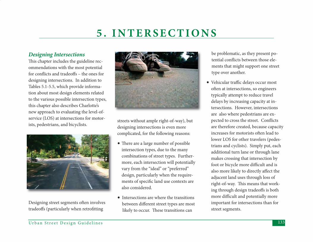
133Ur b a n S t r e e t D e s i g n G u i d e l i n e s
5 . I N T E R S E C T I O N S
Designing IntersectionsTh is chapter includes the guideline rec-ommendations with the most potential for confl icts and tradeoff s – the ones for designing intersections. In addition to Tables 5.1-5.5, which provide informa-tion about most design elements related to the various possible intersection types, this chapter also describes Charlotte’s new approach to evaluating the level-of-service (LOS) at intersections for motor-ists, pedestrians, and bicyclists.
Designing street segments oft en involves tradeoff s (particularly when retrofi tting
streets without ample right-of-way), but designing intersections is even more complicated, for the following reasons:
• Th ere are a large number of possible intersection types, due to the many combinations of street types. Further- more, each intersection will potentially vary from the “ideal” or “preferred” design, particularly when the require- ments of specifi c land use contexts are also considered.
• Intersections are where the transitions between diff erent street types are most likely to occur. Th ese transitions can
be problematic, as they present po- tential confl icts between those ele- ments that might support one street type over another.
• Vehicular traffi c delays occur most oft en at intersections, so engineers typically attempt to reduce travel delays by increasing capacity at in- tersections. However, intersections
are also where pedestrians are ex-pected to cross the street. Confl icts are therefore created, because capacity increases for motorists oft en lead to lower LOS for other travelers (pedes-trians and cyclists). Simply put, each additional turn lane or through lane makes crossing that intersection by foot or bicycle more diffi cult and is also more likely to directly aff ect the adjacent land uses through loss of right-of-way. Th is means that work-ing through design tradeoff s is both more diffi cult and potentially more important for intersections than for street segments.
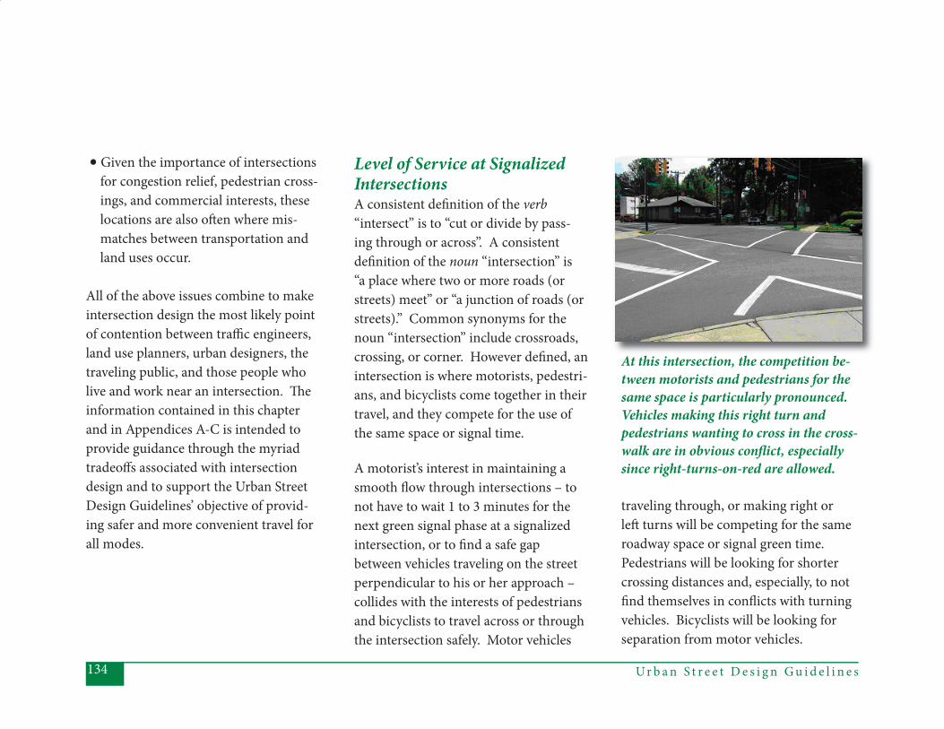
Ur b a n S t r e e t D e s i g n G u i d e l i n e s134
Level of Service at Signalized IntersectionsA consistent defi nition of the verb “intersect” is to “cut or divide by pass-ing through or across”. A consistent defi nition of the noun “intersection” is “a place where two or more roads (or streets) meet” or “a junction of roads (or streets).” Common synonyms for the noun “intersection” include crossroads, crossing, or corner. However defi ned, an intersection is where motorists, pedestri-ans, and bicyclists come together in their travel, and they compete for the use of the same space or signal time.
A motorist’s interest in maintaining a smooth fl ow through intersections – to not have to wait 1 to 3 minutes for the next green signal phase at a signalized intersection, or to fi nd a safe gap between vehicles traveling on the street perpendicular to his or her approach – collides with the interests of pedestrians and bicyclists to travel across or through the intersection safely. Motor vehicles
traveling through, or making right or left turns will be competing for the same roadway space or signal green time. Pedestrians will be looking for shorter crossing distances and, especially, to not fi nd themselves in confl icts with turning vehicles. Bicyclists will be looking for separation from motor vehicles.
At this intersection, the competition be-tween motorists and pedestrians for the same space is particularly pronounced. Vehicles making this right turn and pedestrians wanting to cross in the cross-walk are in obvious confl ict, especially since right-turns-on-red are allowed.
• Given the importance of intersections for congestion relief, pedestrian cross- ings, and commercial interests, these locations are also oft en where mis- matches between transportation and land uses occur.
All of the above issues combine to make intersection design the most likely point of contention between traffi c engineers, land use planners, urban designers, the traveling public, and those people who live and work near an intersection. Th e information contained in this chapter and in Appendices A-C is intended to provide guidance through the myriad tradeoff s associated with intersection design and to support the Urban Street Design Guidelines’ objective of provid-ing safer and more convenient travel for all modes.
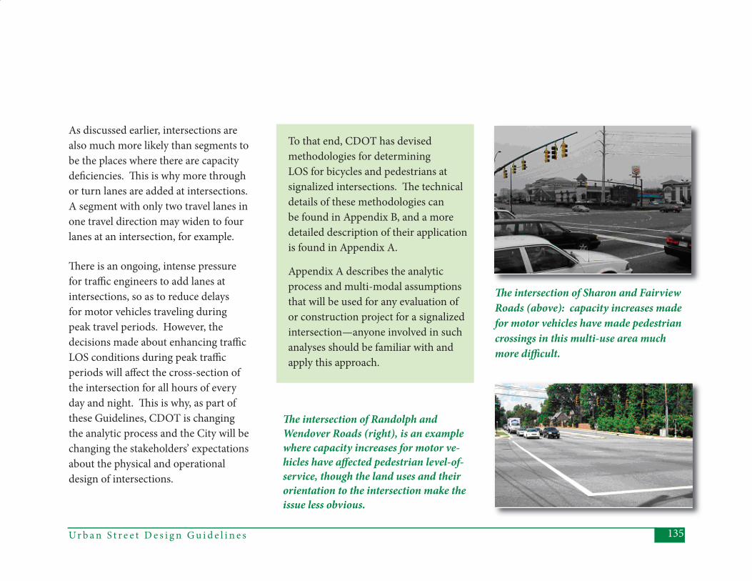
135Ur b a n S t r e e t D e s i g n G u i d e l i n e s
To that end, CDOT has devised methodologies for determining LOS for bicycles and pedestrians at signalized intersections. Th e technical details of these methodologies can be found in Appendix B, and a more detailed description of their application is found in Appendix A.
Appendix A describes the analytic process and multi-modal assumptions that will be used for any evaluation of or construction project for a signalized intersection—anyone involved in such analyses should be familiar with and apply this approach.
As discussed earlier, intersections are also much more likely than segments to be the places where there are capacity defi ciencies. Th is is why more through or turn lanes are added at intersections. A segment with only two travel lanes in one travel direction may widen to four lanes at an intersection, for example.
Th ere is an ongoing, intense pressure for traffi c engineers to add lanes at intersections, so as to reduce delays for motor vehicles traveling during peak travel periods. However, the decisions made about enhancing traffi c LOS conditions during peak traffi c periods will aff ect the cross-section of the intersection for all hours of every day and night. Th is is why, as part of these Guidelines, CDOT is changing the analytic process and the City will be changing the stakeholders’ expectations about the physical and operational design of intersections.
Th e intersection of Randolph andWendover Roads (right), is an example where capacity increases for motor ve-hicles have aff ected pedestrian level-of-service, though the land uses and their orientation to the intersection make the issue less obvious.
Th e intersection of Sharon and Fairview Roads (above): capacity increases made for motor vehicles have made pedestrian crossings in this multi-use area much more diffi cult.
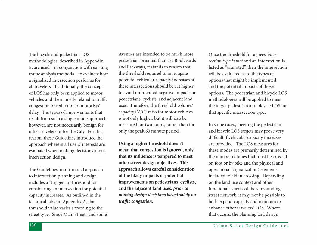
Ur b a n S t r e e t D e s i g n G u i d e l i n e s136
Th e bicycle and pedestrian LOS methodologies, described in Appendix B, are used—in conjunction with existing traffi c analysis methods—to evaluate how a signalized intersection performs for all travelers. Traditionally, the concept of LOS has only been applied to motor vehicles and then mostly related to traffi c congestion or reduction of motorists’ delay. Th e types of improvements that result from such a single mode approach, however, are not necessarily benign for other travelers or for the City. For that reason, these Guidelines introduce the approach wherein all users’ interests are evaluated when making decisions about intersection design.
Th e Guidelines’ multi-modal approach to intersection planning and design includes a “trigger” or threshold for considering an intersection for potential capacity increases. As outlined in the technical table in Appendix A, that threshold value varies according to the street type. Since Main Streets and some
Avenues are intended to be much more pedestrian-oriented than are Boulevards and Parkways, it stands to reason that the threshold required to investigate potential vehicular capacity increases at these intersections should be set higher, to avoid unintended negative impacts on pedestrians, cyclists, and adjacent land uses. Th erefore, the threshold volume/capacity (V/C) ratio for motor vehicles is not only higher, but it will also be measured for two hours, rather than for only the peak 60 minute period.
Using a higher threshold doesn’t mean that congestion is ignored, only that its infl uence is tempered to meet other street design objectives. Th is approach allows careful consideration of the likely impacts of potential improvements on pedestrians, cyclists, and the adjacent land uses, prior to making design decisions based solely on traffi c congestion.
Once the threshold for a given inter-section type is met and an intersection is listed as “saturated”, then the intersection will be evaluated as to the types of options that might be implemented and the potential impacts of those options. Th e pedestrian and bicycle LOS methodologies will be applied to meet the target pedestrian and bicycle LOS for that specifi c intersection type.
In some cases, meeting the pedestrian and bicycle LOS targets may prove very diffi cult if vehicular capacity increases are provided. Th e LOS measures for these modes are primarily determined by the number of lanes that must be crossed on foot or by bike and the physical and operational (signalization) elements included to aid in crossing. Depending on the land use context and other functional aspects of the surrounding street network, it may not be possible to both expand capacity and maintain or enhance other travelers’ LOS. Where that occurs, the planning and design

137Ur b a n S t r e e t D e s i g n G u i d e l i n e s
team should thoroughly evaluate the overall objectives for the intersection in relation to the rest of the network and the City’s goals for provision of multi-modal streets. In many parts of the City, the decision may well be that the capacity improvement cannot or should not occur.
Sight Distance at CornersOnce the decision to make changes at an intersection occurs, the tables found in this chapter are used to decide how, and in which combinations, various design elements should be provided in the design of that intersection. An important design consideration that is not, however, included in Tables 5.1-5.5, is corner sight distance, which impacts the relationship between the street and the buildings adjacent to it.
Sight distance refers to the ability of motorists to see other vehicles or objects in the street without obstructions. Sight distance is applicable where motorists need to decide whether to stop or whether to enter an intersection.
Th ese Urban Street Design Guidelines have some objectives that will change the way that CDOT’s current sight distance recommendations are applied. In general, CDOT’s Sight Distance
Policy will be applied to all intersections, although there are some instances that will call for using the policy with the greatest possible fl exibility. For example, in a very urban or pedestrian-oriented context, there may be a confl ict between sight triangles (the space available for drivers to see each other as they approach an intersection) and the desire to have buildings situated close to the street or even directly behind the sidewalk (Figure
Figure 5.1. Sight Distance Triangles in Urban Locations: Potentially Confl icting Objectives?
Ur b a n S t r e e t D e s i g n G u i d e l i n e s138
5.1). Even with the wider sidewalks and amenity zones found in these areas, meeting the requirement of a strictly applied sight triangle for an adjacent intersection may not be possible or desirable. Likewise, the requirements for departure sight triangles along streets (when pulling out of side streets or driveways), if applied strictly, may confl ict with the desire to provide bus shelters, street furnishings, or enough street trees of suffi cient size to create a canopy.
On the other hand, on streets designed for other contexts, where higher speeds and land uses with deeper setbacks are found, a stricter application of the sight distance recommendations is required. In those cases, the traditional viewpoint of maintaining adequate “room for error” by motorists is necessary for maintaining safety - a worthwhile objective and intended outcome for all streets and intersections defi ned within these Guidelines.
In summary, corner sight distance must be applied carefully, to avoid unintended and potentially negative consequences. As with many of the recommendations contained within these Guidelines, those designing a street should make an eff ort to best match the design outcome to the surrounding context.
Traffi c Signal TimingAs described earlier in this chapter, designing the physical elements of an intersection to satisfy multiple objectives related to motorists, pedestrians, and cyclists can be challenging. Likewise, there are many tradeoff s to consider when timing traffi c signals, because people traveling through one location and using diff erent modes essentially “compete” for green signal time. Specifi c signal timing recommendations are not included in Tables 5.1 – 5.5, but signal timing is an important and complex component of meeting the multi-modal objectives of these Urban Street Design Guidelines.
Why is signal timing so complex? Th e following illustrates some of the diffi culties of satisfying everyone who is impacted by signal timing at an intersection:
• Not surprisingly, most motorists do not like to be stopped by traffi c signals.
Ur b a n S t r e e t D e s i g n G u i d e l i n e s138
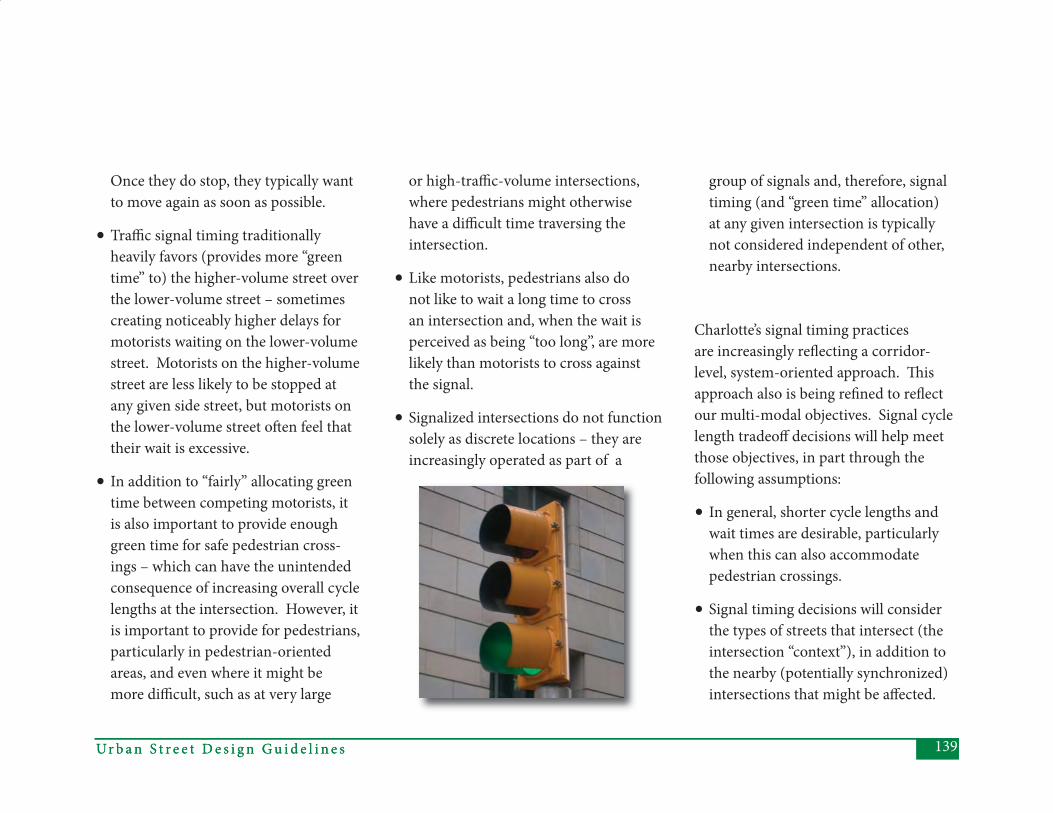
139Ur b a n S t r e e t D e s i g n G u i d e l i n e s
Once they do stop, they typically want to move again as soon as possible.
• Traffi c signal timing traditionally heavily favors (provides more “green time” to) the higher-volume street over the lower-volume street – sometimes creating noticeably higher delays for motorists waiting on the lower-volume street. Motorists on the higher-volume street are less likely to be stopped at any given side street, but motorists on the lower-volume street oft en feel that their wait is excessive.
• In addition to “fairly” allocating green time between competing motorists, it is also important to provide enough green time for safe pedestrian cross-ings – which can have the unintended consequence of increasing overall cycle lengths at the intersection. However, it is important to provide for pedestrians, particularly in pedestrian-oriented areas, and even where it might be more diffi cult, such as at very large
or high-traffi c-volume intersections, where pedestrians might otherwise have a diffi cult time traversing the intersection.
• Like motorists, pedestrians also do not like to wait a long time to cross an intersection and, when the wait is perceived as being “too long”, are more likely than motorists to cross against the signal.
• Signalized intersections do not function solely as discrete locations – they are increasingly operated as part of a
group of signals and, therefore, signal timing (and “green time” allocation) at any given intersection is typically not considered independent of other, nearby intersections.
Charlotte’s signal timing practices are increasingly refl ecting a corridor-level, system-oriented approach. Th is approach also is being refi ned to refl ect our multi-modal objectives. Signal cycle length tradeoff decisions will help meet those objectives, in part through the following assumptions:
• In general, shorter cycle lengths and wait times are desirable, particularly when this can also accommodate pedestrian crossings.
• Signal timing decisions will consider the types of streets that intersect (the intersection “context”), in addition to the nearby (potentially synchronized) intersections that might be aff ected.
139Ur b a n S t r e e t D e s i g n G u i d e l i n e s
Ur b a n S t r e e t D e s i g n G u i d e l i n e s140
• Signal timing decisions will not always heavily favor the higher-volume streets or fl ows, although every attempt will be made to maintain satisfactory throughput.
• Th e objective of minimizing vehicular delay and/or maximizing vehicular throughput is a higher priority for Boulevards and Parkways than for Main Streets or Avenues.
Some of the design elements de-scribed in the following tables rep-resent the “ideal” for which the City is striving, but will require further refi nement for an incremental ap-proach to implementation. In many cases, there are specifi c programs that are responsible for providing such features and it will be neces-sary to update our approaches to refl ect these new Guidelines. Th ese program updates will include evalu-ating the timing required to meet the design goals for most intersec-tions and developing priorities to ensure practical implementation. Elements that will be subject to such evaluation and prioritization include, for example, enhanced crosswalks, audible pedestrian sig-nals, and bicycle detectors.
140
Intersection Design ElementsTables 5.1 – 5.4 describe the features of non-local intersection types (Main Streets, Avenues, Boulevards, and Park-ways). Th e information in these sections is detailed, but not necessarily prescrip-tive. Th e detailed information on dimen-sions should be used by the design team in conjunction with the design method and tradeoff analyses outlined in Chapter 3 and the LOS guidelines discussed above and described in Appendix A. Note that the plan view diagrams do not show dimensions for these street types, as the focus is on understanding and evaluating the tradeoff s among the various uses and users of the right-of-way.
Table 5.5 describes the design elements for local intersections (Residential, Of-fi ce/Commercial, and Industrial). Th e elements and dimensions described are more prescriptive than those for the non-local streets, since these streets are typically provided through the develop-ment process.

141Ur b a n S t r e e t D e s i g n G u i d e l i n e s
Ur b a n S t r e e t D e s i g n G u i d e l i n e s142
Th is section describes the features of all (non-local street) intersections that include at least one Main Street approach to the intersection. Main Streets can intersect with all of the other street types, except for Parkways. With the proper application of these Guidelines, Main Street intersections will be located in a pedestrian-oriented context. Th is is why Main Streets and Parkways should not intersect – because they should exist in mutually exclusive contexts. Th e design of a Main Street intersection will typi-cally favor the pedestrian orientation of the Main Street leg, whether the inter-secting street is a Local Street, an Avenue, or a Boulevard. For example, although Avenues and Boulevards will have higher volumes, more lanes, and higher speeds than do Main Streets, their intersections with Main Streets should be carefully designed to maintain a relatively high pedestrian level-of-service, even with the potential for more through lanes.
General Intent:(1) Pedestrian-oriented design and very good pedestrian level of service (LOS) should guide the design decision for all Main Street intersections (see Appendix A for a description of how to balance pedestrian and bicycle LOS with vehicular LOS).
(2) At Main Street intersections with Avenues and Boulevards, the physi- cal and operational design should particularly provide very good pe- destrian LOS if the Main Street extends across the intersecting street (see Appendix B for a description of the pedestrian LOS methodology).
(3) Some elements will remain constant for all Main Street intersections, such as the use of enhanced pavement markings, countdown signals, not allowing right-turns-on-red, and lim- iting the use of turn lanes onto and off of Main Streets.
Th e following table provides guidance in applying design elements to diff erent types of Main Street intersections. Th e column headings refer to the various possible types of approach legs. Th e “Main Street Approach” column should be used to assess Main-to-Main intersec-tions, as well as the Main Street approach to any of the other intersection types (Main-to-Avenue and Main-to-Boule-vard). Note that the recommendations for Avenues and Boulevards are intended to maintain a relatively high pedestrian LOS at intersections with Main Streets. For a discussion of Main streets inter-secting Local Streets, see “Local Street Intersections,” Section 5.5.
5.1 Main Street Intersections
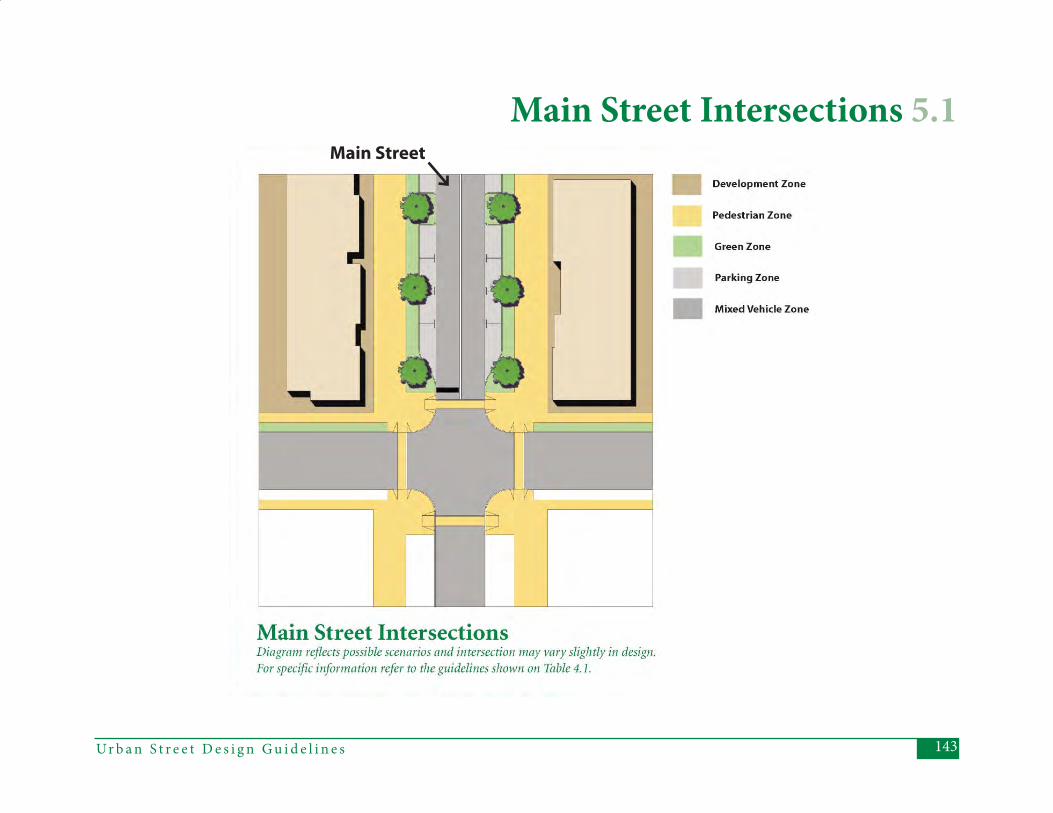
143Ur b a n S t r e e t D e s i g n G u i d e l i n e s
Main Street Intersections 5.1Main Street
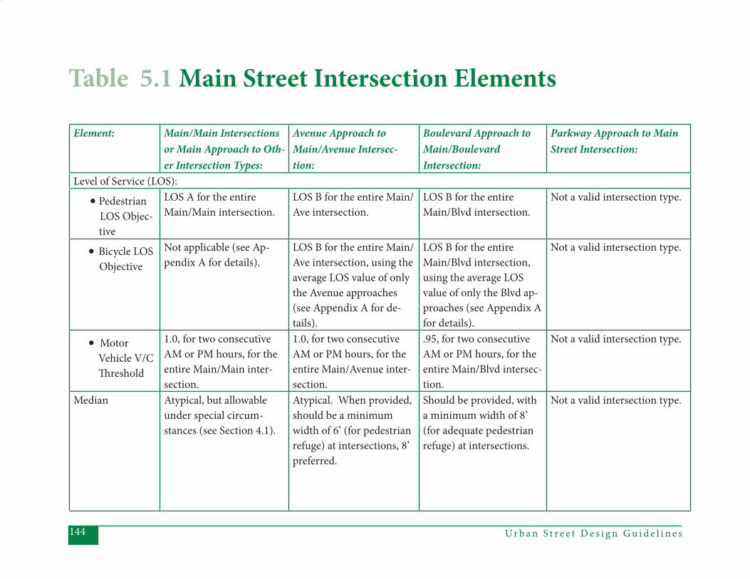
Ur b a n S t r e e t D e s i g n G u i d e l i n e s144
Table 5.1 Main Street Intersection Elements
Element: Main/Main Intersections or Main Approach to Oth-er Intersection Types:
Avenue Approach to Main/Avenue Intersec-tion:
Boulevard Approach to Main/Boulevard Intersection:
Parkway Approach to Main Street Intersection:
Level of Service (LOS):
• Pedestrian LOS Objec-
tive
LOS A for the entire Main/Main intersection.
LOS B for the entire Main/Ave intersection.
LOS B for the entire Main/Blvd intersection.
Not a valid intersection type.
• Bicycle LOS Objective
Not applicable (see Ap-pendix A for details).
LOS B for the entire Main/Ave intersection, using the average LOS value of only the Avenue approaches (see Appendix A for de-tails).
LOS B for the entire Main/Blvd intersection, using the average LOS value of only the Blvd ap-proaches (see Appendix A for details).
Not a valid intersection type.
• Motor Vehicle V/C Th reshold
1.0, for two consecutive AM or PM hours, for the entire Main/Main inter-section.
1.0, for two consecutive AM or PM hours, for the entire Main/Avenue inter-section.
.95, for two consecutive AM or PM hours, for the entire Main/Blvd intersec-tion.
Not a valid intersection type.
Median Atypical, but allowable under special circum-stances (see Section 4.1).
Atypical. When provided, should be a minimum width of 6’ (for pedestrian refuge) at intersections, 8’ preferred.
Should be provided, with a minimum width of 8’ (for adequate pedestrian refuge) at intersections.
Not a valid intersection type.
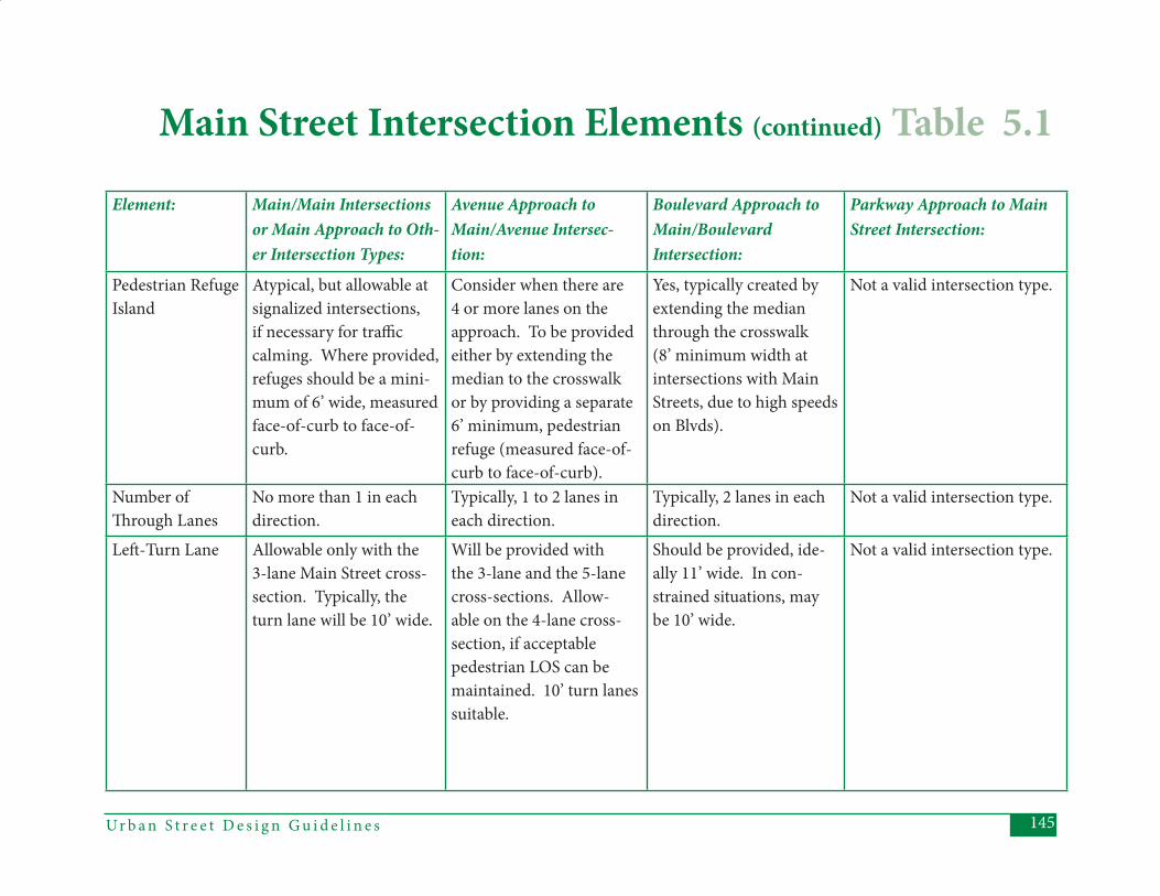
145Ur b a n S t r e e t D e s i g n G u i d e l i n e s
Element: Main/Main Intersections or Main Approach to Oth-er Intersection Types:
Avenue Approach to Main/Avenue Intersec-tion:
Boulevard Approach to Main/Boulevard Intersection:
Parkway Approach to Main Street Intersection:
Pedestrian Refuge Island
Atypical, but allowable at signalized intersections, if necessary for traffi c calming. Where provided, refuges should be a mini-mum of 6’ wide, measured face-of-curb to face-of-curb.
Consider when there are 4 or more lanes on the approach. To be provided either by extending the median to the crosswalk or by providing a separate 6’ minimum, pedestrian refuge (measured face-of-curb to face-of-curb).
Yes, typically created by extending the median through the crosswalk (8’ minimum width at intersections with Main Streets, due to high speeds on Blvds).
Not a valid intersection type.
Number of Th rough Lanes
No more than 1 in each direction.
Typically, 1 to 2 lanes in each direction.
Typically, 2 lanes in each direction.
Not a valid intersection type.
Left -Turn Lane Allowable only with the 3-lane Main Street cross-section. Typically, the turn lane will be 10’ wide.
Will be provided with the 3-lane and the 5-lane cross-sections. Allow-able on the 4-lane cross-section, if acceptable pedestrian LOS can be maintained. 10’ turn lanes suitable.
Should be provided, ide-ally 11’ wide. In con-strained situations, may be 10’ wide.
Not a valid intersection type.
Main Street Intersection Elements (continued) Table 5.1
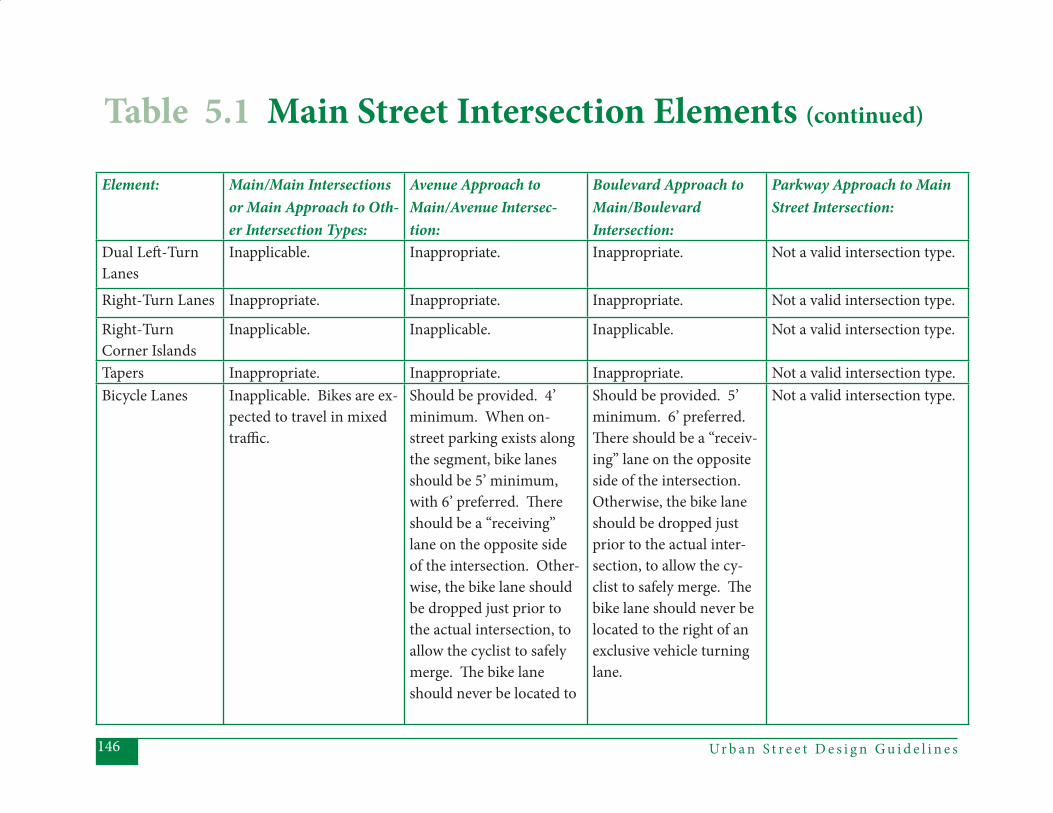
Ur b a n S t r e e t D e s i g n G u i d e l i n e s146
Element: Main/Main Intersections or Main Approach to Oth-er Intersection Types:
Avenue Approach to Main/Avenue Intersec-tion:
Boulevard Approach to Main/Boulevard Intersection:
Parkway Approach to Main Street Intersection:
Dual Left -Turn Lanes
Inapplicable. Inappropriate. Inappropriate. Not a valid intersection type.
Right-Turn Lanes Inappropriate. Inappropriate. Inappropriate. Not a valid intersection type.
Right-Turn Corner Islands
Inapplicable. Inapplicable. Inapplicable. Not a valid intersection type.
Tapers Inappropriate. Inappropriate. Inappropriate. Not a valid intersection type.Bicycle Lanes Inapplicable. Bikes are ex-
pected to travel in mixed traffi c.
Should be provided. 4’ minimum. When on-street parking exists along the segment, bike lanes should be 5’ minimum, with 6’ preferred. Th ere should be a “receiving” lane on the opposite side of the intersection. Other-wise, the bike lane should be dropped just prior to the actual intersection, to allow the cyclist to safely merge. Th e bike lane should never be located to
Should be provided. 5’ minimum. 6’ preferred. Th ere should be a “receiv-ing” lane on the opposite side of the intersection. Otherwise, the bike lane should be dropped just prior to the actual inter-section, to allow the cy-clist to safely merge. Th e bike lane should never be located to the right of an exclusive vehicle turning lane.
Not a valid intersection type.
Table 5.1 Main Street Intersection Elements (continued)
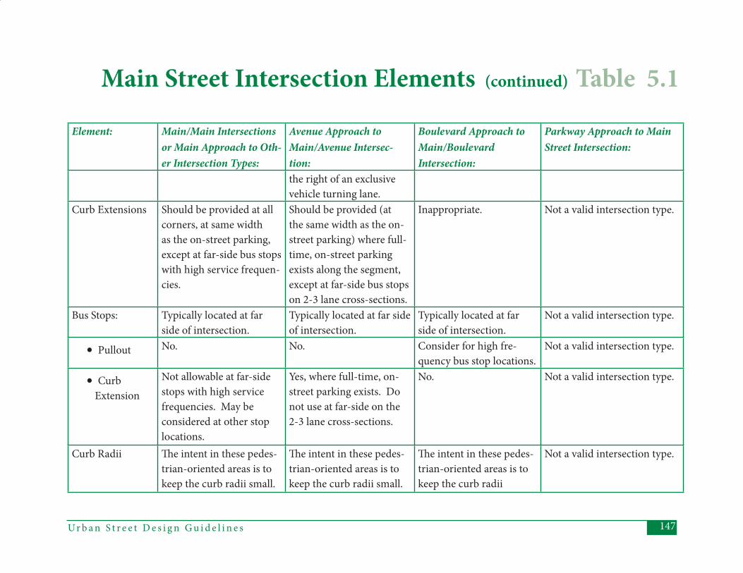
147Ur b a n S t r e e t D e s i g n G u i d e l i n e s
Element: Main/Main Intersections or Main Approach to Oth-er Intersection Types:
Avenue Approach to Main/Avenue Intersec-tion:
Boulevard Approach to Main/Boulevard Intersection:
Parkway Approach to Main Street Intersection:
the right of an exclusive vehicle turning lane.
Curb Extensions Should be provided at all corners, at same width as the on-street parking, except at far-side bus stops with high service frequen-cies.
Should be provided (at the same width as the on-street parking) where full-time, on-street parking exists along the segment, except at far-side bus stops on 2-3 lane cross-sections.
Inappropriate. Not a valid intersection type.
Bus Stops: Typically located at far side of intersection.
Typically located at far side of intersection.
Typically located at far side of intersection.
Not a valid intersection type.
• Pullout No. No. Consider for high fre-quency bus stop locations.
Not a valid intersection type.
• Curb Extension
Not allowable at far-side stops with high service frequencies. May be considered at other stop locations.
Yes, where full-time, on-street parking exists. Do not use at far-side on the 2-3 lane cross-sections.
No. Not a valid intersection type.
Curb Radii Th e intent in these pedes-trian-oriented areas is to keep the curb radii small.
Th e intent in these pedes-trian-oriented areas is to keep the curb radii small.
Th e intent in these pedes-trian-oriented areas is to keep the curb radii
Not a valid intersection type.
Main Street Intersection Elements (continued) Table 5.1
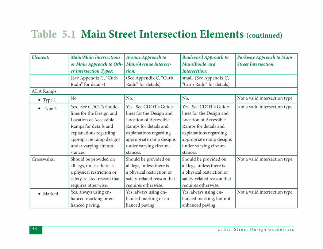
Ur b a n S t r e e t D e s i g n G u i d e l i n e s148
Element: Main/Main Intersections or Main Approach to Oth-er Intersection Types:
Avenue Approach to Main/Avenue Intersec-tion:
Boulevard Approach to Main/Boulevard Intersection:
Parkway Approach to Main Street Intersection:
(See Appendix C, “Curb Radii” for details)
(See Appendix C, “Curb Radii” for details)
small. (See Appendix C, “Curb Radii” for details)
ADA Ramps:
• Type 1 No. No. No. Not a valid intersection type.
• Type 2 Yes. See CDOT’s Guide-lines for the Design and Location of Accessible Ramps for details and explanations regarding appropriate ramp designs under varying circum-stances.
Yes. See CDOT’s Guide-lines for the Design and Location of Accessible Ramps for details and explanations regarding appropriate ramp designs under varying circum-stances.
Yes. See CDOT’s Guide-lines for the Design and Location of Accessible Ramps for details and explanations regarding appropriate ramp designs under varying circum-stances.
Not a valid intersection type.
Crosswalks: Should be provided on all legs, unless there is a physical restriction or safety-related reason that requires otherwise.
Should be provided on all legs, unless there is a physical restriction or safety-related reason that requires otherwise.
Should be provided on all legs, unless there is a physical restriction or safety-related reason that requires otherwise.
Not a valid intersection type.
• Marked Yes, always using en-hanced marking or en-hanced paving.
Yes, always using en-hanced marking or en-hanced paving.
Yes, always using en-hanced marking, but not enhanced paving.
Not a valid intersection type.
Table 5.1 Main Street Intersection Elements (continued)

149Ur b a n S t r e e t D e s i g n G u i d e l i n e s
Element: Main/Main Intersections or Main Approach to Oth-er Intersection Types:
Avenue Approach to Main/Avenue Intersec-tion:
Boulevard Approach to Main/Boulevard Intersection:
Parkway Approach to Main Street Intersection:
• Location Should not be located on the radius.
Should not be located on the radius.
Should not be located on the radius.
Not a valid intersection type.
Traffi c Control:
• Two-Way Stop
No. A Main/Main inter-section, if stop-controlled, should be a four-way stop.
No. No. Not a valid intersection type.
• Four-Way Stop
Allowable if both streets are two-lane and estab-lished warrants are met.
Allowable if both streets are two-lane and signal warrants not met.
No. Not a valid intersection type.
• Roundabout Allowable, except at inter-sections with Boulevards.
Allowable, as a gateway transition.
No. Not a valid intersection type.
• Signals Yes, depending on war-rants. Bus priority should be used where appropri-ate.
Yes, depending on war-rants. Bus priority should be used where appropriate.
Yes. Bus priority should be used where appropri-ate.
Not a valid intersection type.
• Right- Turn on Red
No. No. No. Not a valid intersection type.
• Pedestrian Signals
Yes, with countdown. Where possible, the countdown should show the total number of
Yes, with countdown. Where possible, the count-down should show the total number of seconds
Yes, with countdown. Where possible, the countdown should show the total number of
Not a valid intersection type.
Main Street Intersection Elements (continued) Table 5.1
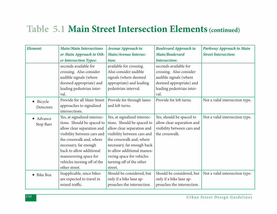
Ur b a n S t r e e t D e s i g n G u i d e l i n e s150
Element: Main/Main Intersections or Main Approach to Oth-er Intersection Types:
Avenue Approach to Main/Avenue Intersec-tion:
Boulevard Approach to Main/Boulevard Intersection:
Parkway Approach to Main Street Intersection:
seconds available for crossing. Also consider audible signals (where deemed appropriate) and leading pedestrian inter-val.
available for crossing. Also consider audible signals (where deemed appropriate) and leading pedestrian interval.
seconds available for crossing. Also consider audible signals (where deemed appropriate) and leading pedestrian inter-val.
• Bicycle Detectors
Provide for all Main Street approaches to signalized intersections.
Provide for through lanes and left turns.
Provide for left turns. Not a valid intersection type.
• Advance Stop Bars
Yes, at signalized intersec-tions. Should be spaced to allow clear separation and visibility between cars and the crosswalk and, where necessary, far enough back to allow additional maneuvering space for vehicles turning off of the other street.
Yes, at signalized intersec-tions. Should be spaced to allow clear separation and visibility between cars and the crosswalk and, where necessary, far enough back to allow additional maneu-vering space for vehicles turning off of the other street.
Yes, should be spaced to allow clear separation and visibility between cars and the crosswalk.
Not a valid intersection type.
• Bike Box Inapplicable, since bikes are expected to travel in mixed traffi c.
Should be considered, but only if a bike lane ap-proaches the intersection.
Should be considered, but only if a bike lane ap-proaches the intersec tion.
Not a valid intersection type.
Table 5.1 Main Street Intersection Elements (continued)
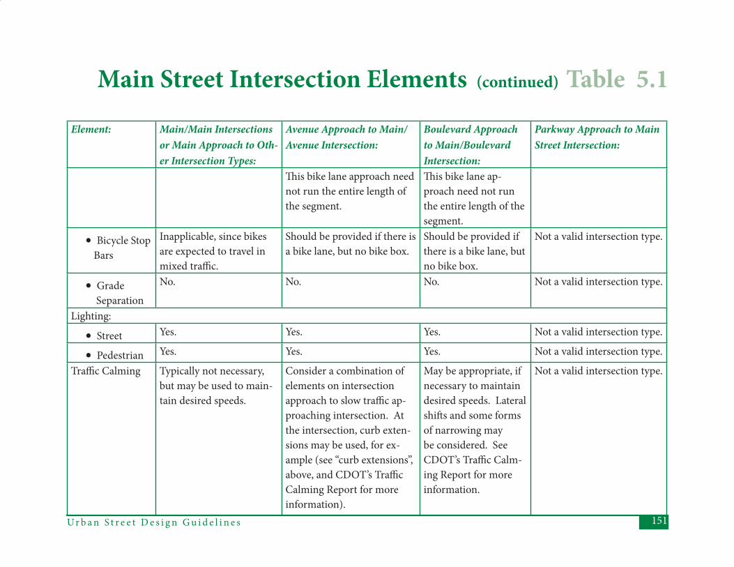
151Ur b a n S t r e e t D e s i g n G u i d e l i n e s
Element: Main/Main Intersections or Main Approach to Oth-er Intersection Types:
Avenue Approach to Main/Avenue Intersection:
Boulevard Approach to Main/Boulevard Intersection:
Parkway Approach to Main Street Intersection:
Th is bike lane approach need not run the entire length of the segment.
Th is bike lane ap-proach need not run the entire length of the segment.
• Bicycle Stop Bars
Inapplicable, since bikes are expected to travel in mixed traffi c.
Should be provided if there is a bike lane, but no bike box.
Should be provided if there is a bike lane, but no bike box.
Not a valid intersection type.
• Grade Separation
No. No. No. Not a valid intersection type.
Lighting:
• Street Yes. Yes. Yes. Not a valid intersection type.
• Pedestrian Yes. Yes. Yes. Not a valid intersection type.
Traffi c Calming Typically not necessary, but may be used to main-tain desired speeds.
Consider a combination of elements on intersection approach to slow traffi c ap-proaching intersection. At the intersection, curb exten-sions may be used, for ex-ample (see “curb extensions”, above, and CDOT’s Traffi c Calming Report for more information).
May be appropriate, if necessary to maintain desired speeds. Lateral shift s and some forms of narrowing may be considered. See CDOT’s Traffi c Calm-ing Report for more information.
Not a valid intersection type.
Main Street Intersection Elements (continued) Table 5.1
Ur b a n S t r e e t D e s i g n G u i d e l i n e s152
Th is section describes the features of all (non-local street) intersections that include at least one Avenue approach to the intersection. Avenues serve a wide variety of land uses and transportation functions. Th ey are expected to provide a safety and comfort balance among the various modes in all contexts. Th e major-ity of non-local street intersections will be with Avenues. Th ere are also several potential cross-sections for Avenues. Th e mix of possible land uses, cross-sections, and intersection types, along with the desire to provide a balance among the modes, makes Avenue intersections the most complicated in many respects. At intersections with Parkways, in par-ticular, providing the necessary modal balance may prove diffi cult and plan/de-sign teams might consider transitioning the Parkway to a Boulevard prior to the approach. A pedestrian-oriented Av-enue should typically not intersect with a Parkway, if at all possible.
General Intent:(1) Design decisions will assess and com- pare the tradeoff s of safe and effi cient travel for motorists, pedestrians, and cyclists.
(2) Capacity increases or delay reduc- tions at Avenue intersections will be carefully evaluated against the im- pacts to all travelers and their level- of-service, as well as the impacts on adjacent land uses.
Th e following table provides guidance in applying design elements to diff erent types of Avenue intersections. Th e col-umn headings refer to the various pos-sible types of approach legs. Th e “Avenue Approach” column should be used to assess Avenue-to-Avenue intersections, as well as the Avenue approach to any of the other intersection types (Avenue-to-Main and Avenue-to-Boulevard). For a discussion of Avenues intersecting Local Streets, see “Local Street Intersections”, Section 5.5.
5.2 Avenue Intersections
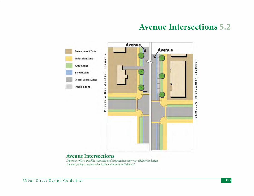
153Ur b a n S t r e e t D e s i g n G u i d e l i n e s
Avenue Intersections 5.2
Avenue
Avenue
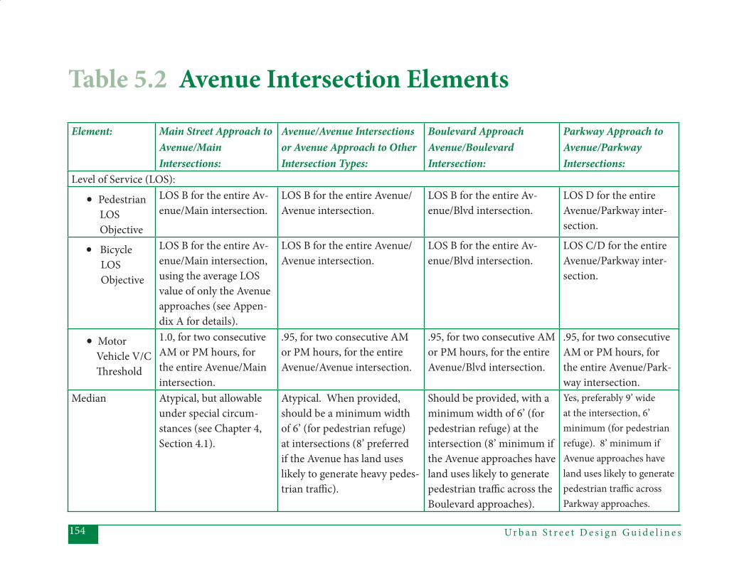
Ur b a n S t r e e t D e s i g n G u i d e l i n e s154
Table 5.2 Avenue Intersection Elements
Element: Main Street Approach to Avenue/Main Intersections:
Avenue/Avenue Intersections or Avenue Approach to Other Intersection Types:
Boulevard Approach Avenue/Boulevard Intersection:
Parkway Approach to Avenue/Parkway Intersections:
Level of Service (LOS):
• Pedestrian LOS Objective
LOS B for the entire Av-enue/Main intersection.
LOS B for the entire Avenue/Avenue intersection.
LOS B for the entire Av-enue/Blvd intersection.
LOS D for the entire Avenue/Parkway inter-section.
• Bicycle LOS Objective
LOS B for the entire Av-enue/Main intersection, using the average LOS value of only the Avenue approaches (see Appen-dix A for details).
LOS B for the entire Avenue/Avenue intersection.
LOS B for the entire Av-enue/Blvd intersection.
LOS C/D for the entire Avenue/Parkway inter-section.
• Motor Vehicle V/C Th reshold
1.0, for two consecutive AM or PM hours, for the entire Avenue/Main intersection.
.95, for two consecutive AM or PM hours, for the entire Avenue/Avenue intersection.
.95, for two consecutive AM or PM hours, for the entire Avenue/Blvd intersection.
.95, for two consecutive AM or PM hours, for the entire Avenue/Park-way intersection.
Median Atypical, but allowable under special circum-stances (see Chapter 4, Section 4.1).
Atypical. When provided, should be a minimum width of 6’ (for pedestrian refuge) at intersections (8’ preferred if the Avenue has land uses likely to generate heavy pedes-trian traffi c).
Should be provided, with a minimum width of 6’ (for pedestrian refuge) at the intersection (8’ minimum if the Avenue approaches have land uses likely to generate pedestrian traffi c across the Boulevard approaches).
Yes, preferably 9’ wide at the intersection, 6’ minimum (for pedestrian refuge). 8’ minimum if Avenue approaches have land uses likely to generate pedestrian traffi c across Parkway approaches.
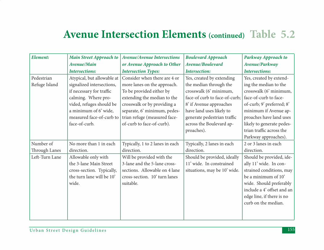
155Ur b a n S t r e e t D e s i g n G u i d e l i n e s
Element: Main Street Approach to Avenue/Main Intersections:
Avenue/Avenue Intersections or Avenue Approach to Other Intersection Types:
Boulevard Approach Avenue/Boulevard Intersection:
Parkway Approach to Avenue/Parkway Intersections:
Pedestrian Refuge Island
Atypical, but allowable at signalized intersections, if necessary for traffi c calming. Where pro-vided, refuges should be a minimum of 6’ wide, measured face-of-curb to face-of-curb.
Consider when there are 4 or more lanes on the approach. To be provided either by extending the median to the crosswalk or by providing a separate, 6’ minimum, pedes-trian refuge (measured face-of-curb to face-of-curb).
Yes, created by extending the median through the crosswalk (6’ minimum, face-of curb to face-of-curb; 8’ if Avenue approaches have land uses likely to generate pedestrian traffi c across the Boulevard ap-proaches).
Yes, created by extend-ing the median to the crosswalk (6’ minimum, face-of-curb to face-of-curb; 9’ preferred; 8’ minimum if Avenue ap-proaches have land uses likely to generate pedes-trian traffi c across the Parkway approaches).
Number of Th rough Lanes
No more than 1 in each direction.
Typically, 1 to 2 lanes in each direction.
Typically, 2 lanes in each direction.
2 or 3 lanes in each direction.
Left -Turn Lane Allowable only with the 3-lane Main Street cross-section. Typically, the turn lane will be 10’ wide.
Will be provided with the 3-lane and the 5-lane cross-sections. Allowable on 4 lane cross-section. 10’ turn lanes suitable.
Should be provided, ideally 11’ wide. In constrained situations, may be 10’ wide.
Should be provided, ide-ally 11’ wide. In con-strained conditions, may be a minimum of 10’ wide. Should preferably include a 4’ off set and an edge line, if there is no curb on the median.
Avenue Intersection Elements (continued) Table 5.2
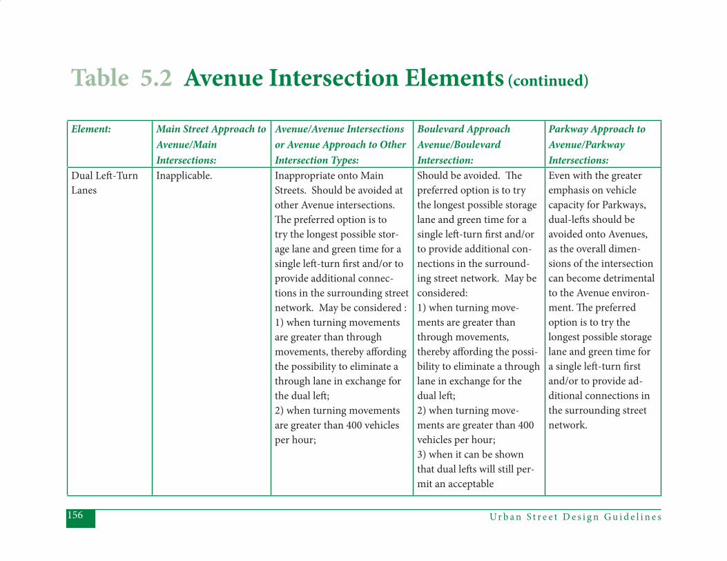
Ur b a n S t r e e t D e s i g n G u i d e l i n e s156
Element: Main Street Approach to Avenue/Main Intersections:
Avenue/Avenue Intersections or Avenue Approach to Other Intersection Types:
Boulevard Approach Avenue/Boulevard Intersection:
Parkway Approach to Avenue/Parkway Intersections:
Dual Left -Turn Lanes
Inapplicable. Inappropriate onto Main Streets. Should be avoided at other Avenue intersections. Th e preferred option is to try the longest possible stor-age lane and green time for a single left -turn fi rst and/or to provide additional connec-tions in the surrounding street network. May be considered :1) when turning movements are greater than through movements, thereby aff ording the possibility to eliminate a through lane in exchange for the dual left ; 2) when turning movements are greater than 400 vehicles per hour;
Should be avoided. Th e preferred option is to try the longest possible storage lane and green time for a single left -turn fi rst and/or to provide additional con-nections in the surround-ing street network. May be considered:1) when turning move-ments are greater than through movements, thereby aff ording the possi-bility to eliminate a through lane in exchange for the dual left ; 2) when turning move-ments are greater than 400 vehicles per hour; 3) when it can be shown that dual left s will still per-mit an acceptable
Even with the greater emphasis on vehicle capacity for Parkways, dual-left s should be avoided onto Avenues, as the overall dimen-sions of the intersection can become detrimental to the Avenue environ-ment. Th e preferred option is to try the longest possible storage lane and green time for a single left -turn fi rst and/or to provide ad-ditional connections in the surrounding street network.
Table 5.2 Avenue Intersection Elements (continued)
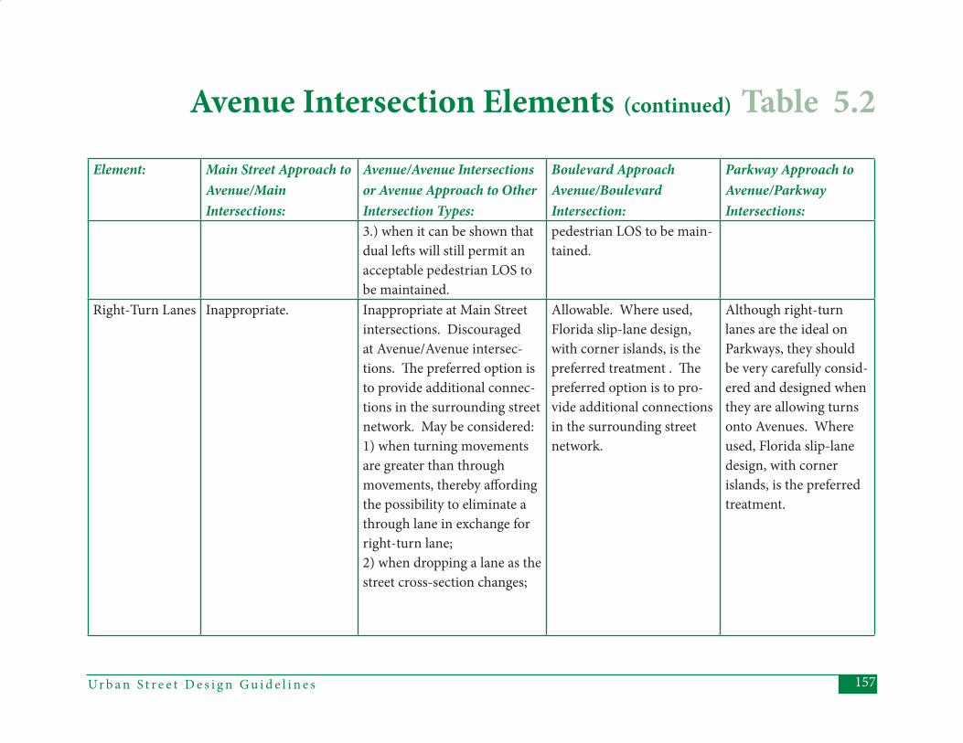
157Ur b a n S t r e e t D e s i g n G u i d e l i n e s
Element: Main Street Approach to Avenue/Main Intersections:
Avenue/Avenue Intersections or Avenue Approach to Other Intersection Types:
Boulevard Approach Avenue/Boulevard Intersection:
Parkway Approach to Avenue/Parkway Intersections:
3.) when it can be shown that dual left s will still permit an acceptable pedestrian LOS to be maintained.
pedestrian LOS to be main-tained.
Right-Turn Lanes Inappropriate. Inappropriate at Main Street intersections. Discouraged at Avenue/Avenue intersec-tions. Th e preferred option is to provide additional connec-tions in the surrounding street network. May be considered:1) when turning movements are greater than through movements, thereby aff ording the possibility to eliminate a through lane in exchange for right-turn lane;2) when dropping a lane as the street cross-section changes;
Allowable. Where used, Florida slip-lane design, with corner islands, is the preferred treatment . Th e preferred option is to pro-vide additional connections in the surrounding street network.
Although right-turn lanes are the ideal on Parkways, they should be very carefully consid-ered and designed when they are allowing turns onto Avenues. Where used, Florida slip-lane design, with corner islands, is the preferred treatment.
Avenue Intersection Elements (continued) Table 5.2
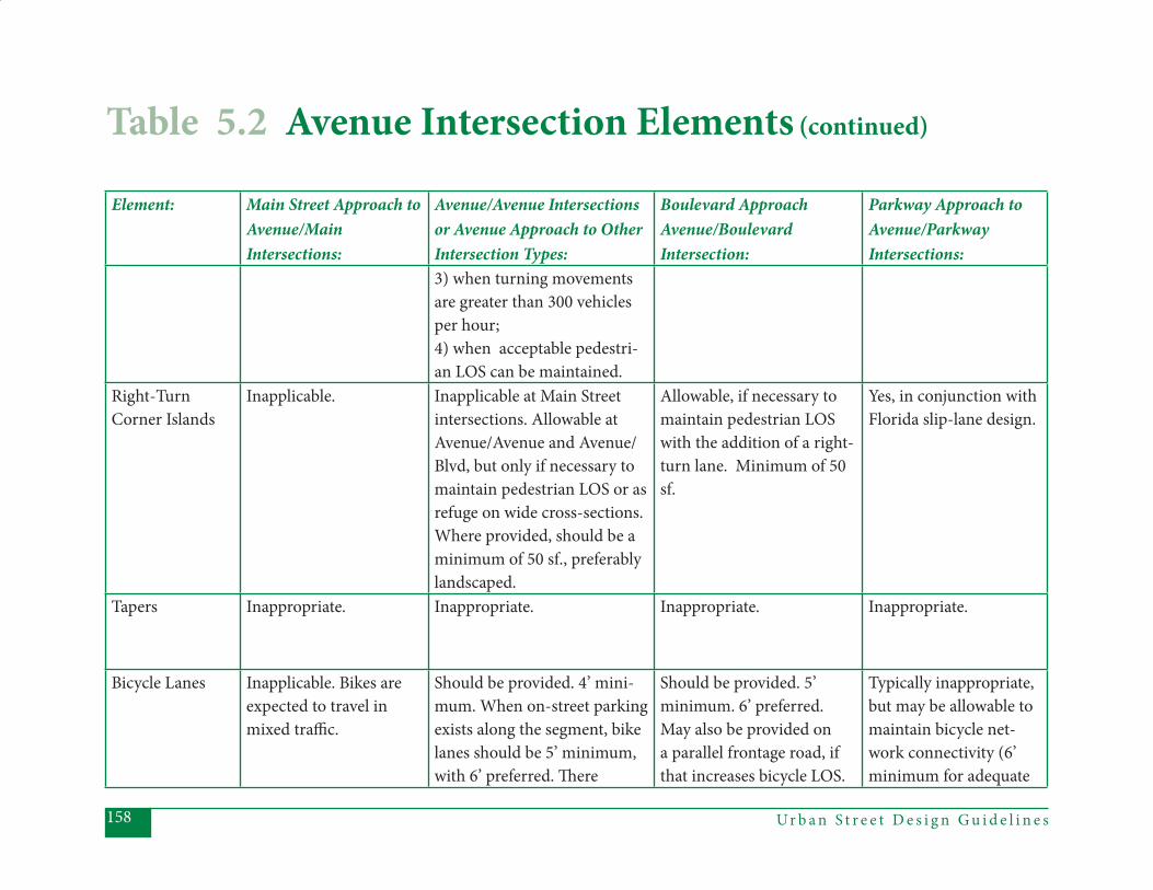
Ur b a n S t r e e t D e s i g n G u i d e l i n e s158
Element: Main Street Approach to Avenue/Main Intersections:
Avenue/Avenue Intersections or Avenue Approach to Other Intersection Types:
Boulevard Approach Avenue/Boulevard Intersection:
Parkway Approach to Avenue/Parkway Intersections:
3) when turning movements are greater than 300 vehicles per hour;4) when acceptable pedestri-an LOS can be maintained.
Right-Turn Corner Islands
Inapplicable. Inapplicable at Main Street intersections. Allowable at Avenue/Avenue and Avenue/Blvd, but only if necessary to maintain pedestrian LOS or as refuge on wide cross-sections. Where provided, should be a minimum of 50 sf., preferably landscaped.
Allowable, if necessary to maintain pedestrian LOS with the addition of a right-turn lane. Minimum of 50 sf.
Yes, in conjunction with Florida slip-lane design.
Tapers Inappropriate. Inappropriate. Inappropriate. Inappropriate.
Bicycle Lanes Inapplicable. Bikes are expected to travel in mixed traffi c.
Should be provided. 4’ mini-mum. When on-street parking exists along the segment, bike lanes should be 5’ minimum, with 6’ preferred. Th ere
Should be provided. 5’ minimum. 6’ preferred. May also be provided on a parallel frontage road, if that increases bicycle LOS.
Typically inappropriate, but may be allowable to maintain bicycle net-work connectivity (6’ minimum for adequate
Table 5.2 Avenue Intersection Elements (continued)
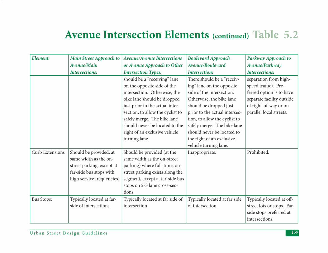
159Ur b a n S t r e e t D e s i g n G u i d e l i n e s
Element: Main Street Approach to Avenue/Main Intersections:
Avenue/Avenue Intersections or Avenue Approach to Other Intersection Types:
Boulevard Approach Avenue/Boulevard Intersection:
Parkway Approach to Avenue/Parkway Intersections:
should be a “receiving” lane on the opposite side of the intersection. Otherwise, the bike lane should be dropped just prior to the actual inter-section, to allow the cyclist to safely merge. Th e bike lane should never be located to the right of an exclusive vehicle turning lane.
Th ere should be a “receiv-ing” lane on the opposite side of the intersection. Otherwise, the bike lane should be dropped just prior to the actual intersec-tion, to allow the cyclist to safely merge. Th e bike lane should never be located to the right of an exclusive vehicle turning lane.
separation from high-speed traffi c). Pre-ferred option is to have separate facility outside of right-of-way or on parallel local streets.
Curb Extensions Should be provided, at same width as the on-street parking, except at far-side bus stops with high service frequencies.
Should be provided (at the same width as the on-street parking) where full-time, on-street parking exists along the segment, except at far-side bus stops on 2-3 lane cross-sec-tions.
Inappropriate. Prohibited.
Bus Stops: Typically located at far-side of intersections.
Typically located at far side of intersection.
Typically located at far side of intersection.
Typically located at off -street lots or stops. Far side stops preferred at intersections.
Avenue Intersection Elements (continued) Table 5.2
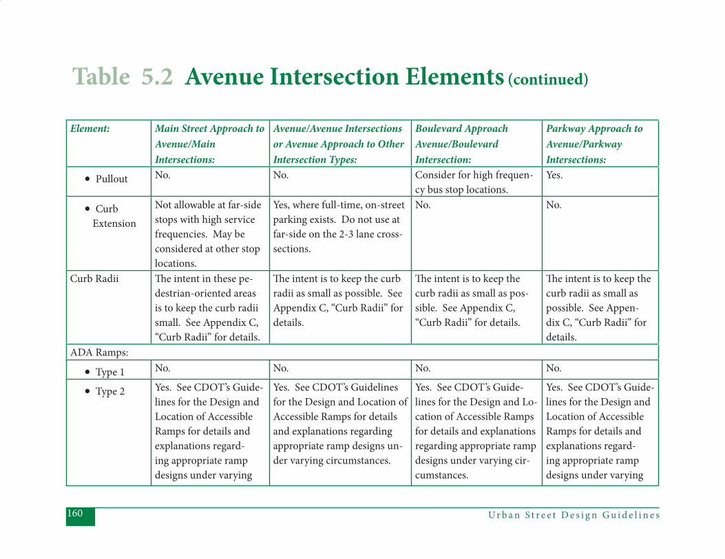
Ur b a n S t r e e t D e s i g n G u i d e l i n e s160
Element: Main Street Approach to Avenue/Main Intersections:
Avenue/Avenue Intersections or Avenue Approach to Other Intersection Types:
Boulevard Approach Avenue/Boulevard Intersection:
Parkway Approach to Avenue/Parkway Intersections:
• Pullout No. No. Consider for high frequen-cy bus stop locations.
Yes.
• Curb Extension
Not allowable at far-side stops with high service frequencies. May be considered at other stop locations.
Yes, where full-time, on-street parking exists. Do not use at far-side on the 2-3 lane cross-sections.
No. No.
Curb Radii Th e intent in these pe-destrian-oriented areas is to keep the curb radii small. See Appendix C, “Curb Radii” for details.
Th e intent is to keep the curb radii as small as possible. See Appendix C, “Curb Radii” for details.
Th e intent is to keep the curb radii as small as pos-sible. See Appendix C, “Curb Radii” for details.
Th e intent is to keep the curb radii as small as possible. See Appen-dix C, “Curb Radii” for details.
ADA Ramps:
• Type 1 No. No. No. No.
• Type 2 Yes. See CDOT’s Guide-lines for the Design and Location of Accessible Ramps for details and explanations regard-ing appropriate ramp designs under varying
Yes. See CDOT’s Guidelines for the Design and Location of Accessible Ramps for details and explanations regarding appropriate ramp designs un-der varying circumstances.
Yes. See CDOT’s Guide-lines for the Design and Lo-cation of Accessible Ramps for details and explanations regarding appropriate ramp designs under varying cir-cumstances.
Yes. See CDOT’s Guide-lines for the Design and Location of Accessible Ramps for details and explanations regard-ing appropriate ramp designs under varying
Table 5.2 Avenue Intersection Elements (continued)
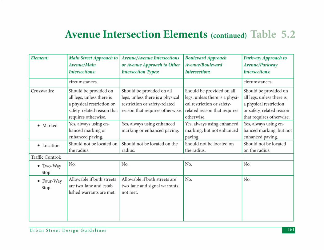
161Ur b a n S t r e e t D e s i g n G u i d e l i n e s
Element: Main Street Approach to Avenue/Main Intersections:
Avenue/Avenue Intersections or Avenue Approach to Other Intersection Types:
Boulevard Approach Avenue/Boulevard Intersection:
Parkway Approach to Avenue/Parkway Intersections:
circumstances. circumstances.
Crosswalks: Should be provided on all legs, unless there is a physical restriction or safety-related reason thatrequires otherwise.
Should be provided on all legs, unless there is a physical restriction or safety-related reason that requires otherwise.
Should be provided on all legs, unless there is a physi-cal restriction or safety-related reason that requires otherwise.
Should be provided on all legs, unless there is a physical restriction or safety-related reason that requires otherwise.
• Marked Yes, always using en-hanced marking or enhanced paving.
Yes, always using enhanced marking or enhanced paving.
Yes, always using enhanced marking, but not enhanced paving.
Yes, always using en-hanced marking, but not enhanced paving.
• Location Should not be located on the radius.
Should not be located on the radius.
Should not be located on the radius.
Should not be located on the radius.
Traffi c Control:
• Two-Way Stop
No. No. No. No.
• Four-Way Stop
Allowable if both streets are two-lane and estab-lished warrants are met.
Allowable if both streets are two-lane and signal warrants not met.
No. No.
Avenue Intersection Elements (continued) Table 5.2

Ur b a n S t r e e t D e s i g n G u i d e l i n e s162
Element: Main Street Approach to Avenue/Main Intersections:
Avenue/Avenue Intersections or Avenue Approach to Other Intersection Types:
Boulevard Approach Avenue/Boulevard Intersection:
Parkway Approach to Avenue/Parkway Intersections:
• Round- about
Allowable as a gateway transition.
Allowable as a gateway transi-tion at Main Streets. Allowable elsewhere, when: 1) volumes are less than 35,000; 2) analysis shows that round-abouts provide higher vehicle LOS than signals; and 3) provision of roundabout does not degrade pedestrian and bicycle LOS.
Allowable, when: 1) volumes are less than 35,000; 2) analysis shows that roundabouts provide higher vehicle LOS than signals; and 3) provision of roundabout does not degrade pedestrian and bicycle LOS.
No.
• Signals Yes, depending on warrants. Bus priority should be used where appropriate.
Yes. Bus priority should be used where appropriate.
Yes. Bus priority should be used where appropriate.
Yes. Bus priority should be used where appropri-ate.
• Right-Turn on Red
No. Not at Main Street intersec-tions. Allowable at other intersections, but should be avoided in locations with a high potential for pedestrian traffi c (in areas that are cur-rently or are planned to be
Allowable, but should be avoided in locations with a high potential for pedes-trian traffi c (in areas that are currently or are planned to be pedestrian-oriented or mixed-use).
Desirable, depending on sight distance and potential for higher vol-ume pedestrian traffi c at the intersection.
Table 5.2 Avenue Intersection Elements (continued)
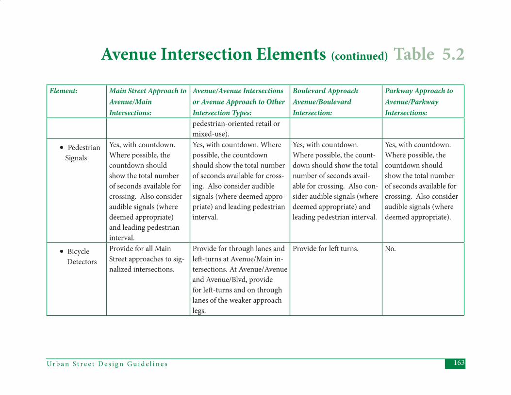
163Ur b a n S t r e e t D e s i g n G u i d e l i n e s
Element: Main Street Approach to Avenue/Main Intersections:
Avenue/Avenue Intersections or Avenue Approach to Other Intersection Types:
Boulevard Approach Avenue/Boulevard Intersection:
Parkway Approach to Avenue/Parkway Intersections:
pedestrian-oriented retail or mixed-use).
• Pedestrian Signals
Yes, with countdown. Where possible, the countdown should show the total number of seconds available for crossing. Also consider audible signals (where deemed appropriate) and leading pedestrian interval.
Yes, with countdown. Where possible, the countdown should show the total number of seconds available for cross-ing. Also consider audible signals (where deemed appro-priate) and leading pedestrian interval.
Yes, with countdown. Where possible, the count-down should show the total number of seconds avail-able for crossing. Also con-sider audible signals (where deemed appropriate) and leading pedestrian interval.
Yes, with countdown. Where possible, the countdown should show the total number of seconds available for crossing. Also consider audible signals (where deemed appropriate).
• Bicycle Detectors
Provide for all Main Street approaches to sig-nalized intersections.
Provide for through lanes and left -turns at Avenue/Main in-tersections. At Avenue/Avenue and Avenue/Blvd, provide for left -turns and on through lanes of the weaker approach legs.
Provide for left turns. No.
Avenue Intersection Elements (continued) Table 5.2
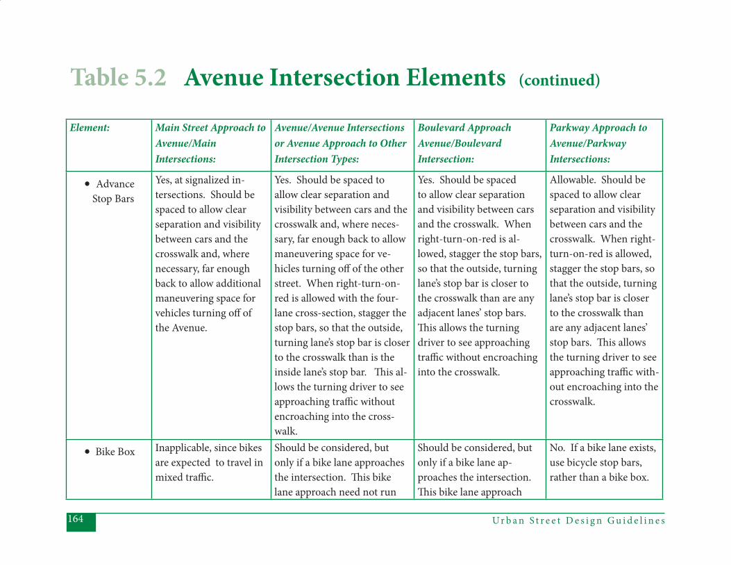
Ur b a n S t r e e t D e s i g n G u i d e l i n e s164
Element: Main Street Approach to Avenue/Main Intersections:
Avenue/Avenue Intersections or Avenue Approach to Other Intersection Types:
Boulevard Approach Avenue/Boulevard Intersection:
Parkway Approach to Avenue/Parkway Intersections:
• Advance Stop Bars
Yes, at signalized in-tersections. Should be spaced to allow clear separation and visibility between cars and the crosswalk and, where necessary, far enough back to allow additional maneuvering space for vehicles turning off of the Avenue.
Yes. Should be spaced to allow clear separation and visibility between cars and the crosswalk and, where neces-sary, far enough back to allow maneuvering space for ve-hicles turning off of the other street. When right-turn-on-red is allowed with the four-lane cross-section, stagger the stop bars, so that the outside, turning lane’s stop bar is closer to the crosswalk than is the inside lane’s stop bar. Th is al-lows the turning driver to see approaching traffi c without encroaching into the cross-walk.
Yes. Should be spaced to allow clear separation and visibility between cars and the crosswalk. When right-turn-on-red is al-lowed, stagger the stop bars, so that the outside, turning lane’s stop bar is closer to the crosswalk than are any adjacent lanes’ stop bars. Th is allows the turning driver to see approaching traffi c without encroaching into the crosswalk.
Allowable. Should be spaced to allow clear separation and visibility between cars and the crosswalk. When right-turn-on-red is allowed, stagger the stop bars, so that the outside, turning lane’s stop bar is closer to the crosswalk than are any adjacent lanes’ stop bars. Th is allowsthe turning driver to see approaching traffi c with-out encroaching into the crosswalk.
• Bike Box Inapplicable, since bikes are expected to travel in mixed traffi c.
Should be considered, but only if a bike lane approaches the intersection. Th is bike lane approach need not run
Should be considered, but only if a bike lane ap-proaches the intersection. Th is bike lane approach
No. If a bike lane exists, use bicycle stop bars, rather than a bike box.
Table 5.2 Avenue Intersection Elements (continued)
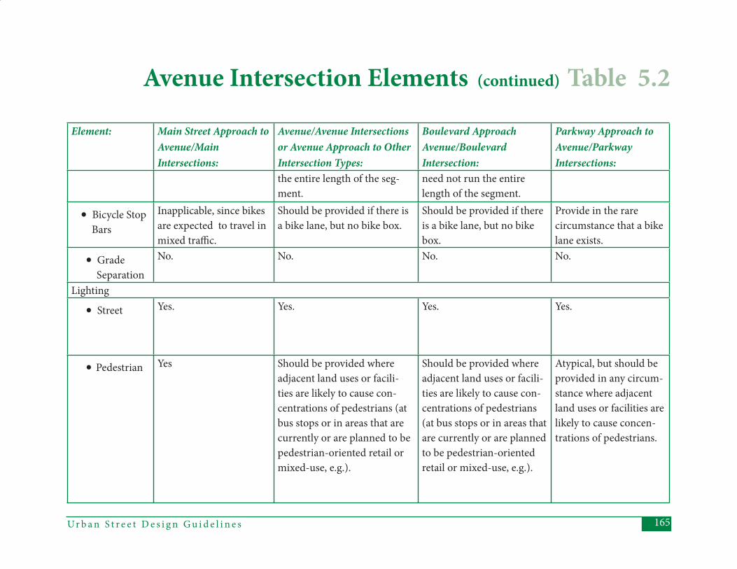
165Ur b a n S t r e e t D e s i g n G u i d e l i n e s
Element: Main Street Approach to Avenue/Main Intersections:
Avenue/Avenue Intersections or Avenue Approach to Other Intersection Types:
Boulevard Approach Avenue/Boulevard Intersection:
Parkway Approach to Avenue/Parkway Intersections:
the entire length of the seg-ment.
need not run the entire length of the segment.
• Bicycle Stop Bars
Inapplicable, since bikes are expected to travel in mixed traffi c.
Should be provided if there is a bike lane, but no bike box.
Should be provided if there is a bike lane, but no bike box.
Provide in the rare circumstance that a bike lane exists.
• Grade Separation
No. No. No. No.
Lighting
• Street Yes. Yes. Yes. Yes.
• Pedestrian Yes Should be provided where adjacent land uses or facili-ties are likely to cause con-centrations of pedestrians (at bus stops or in areas that are currently or are planned to be pedestrian-oriented retail or mixed-use, e.g.).
Should be provided where adjacent land uses or facili-ties are likely to cause con-centrations of pedestrians (at bus stops or in areas that are currently or are planned to be pedestrian-oriented retail or mixed-use, e.g.).
Atypical, but should be provided in any circum-stance where adjacent land uses or facilities are likely to cause concen-trations of pedestrians.
Avenue Intersection Elements (continued) Table 5.2
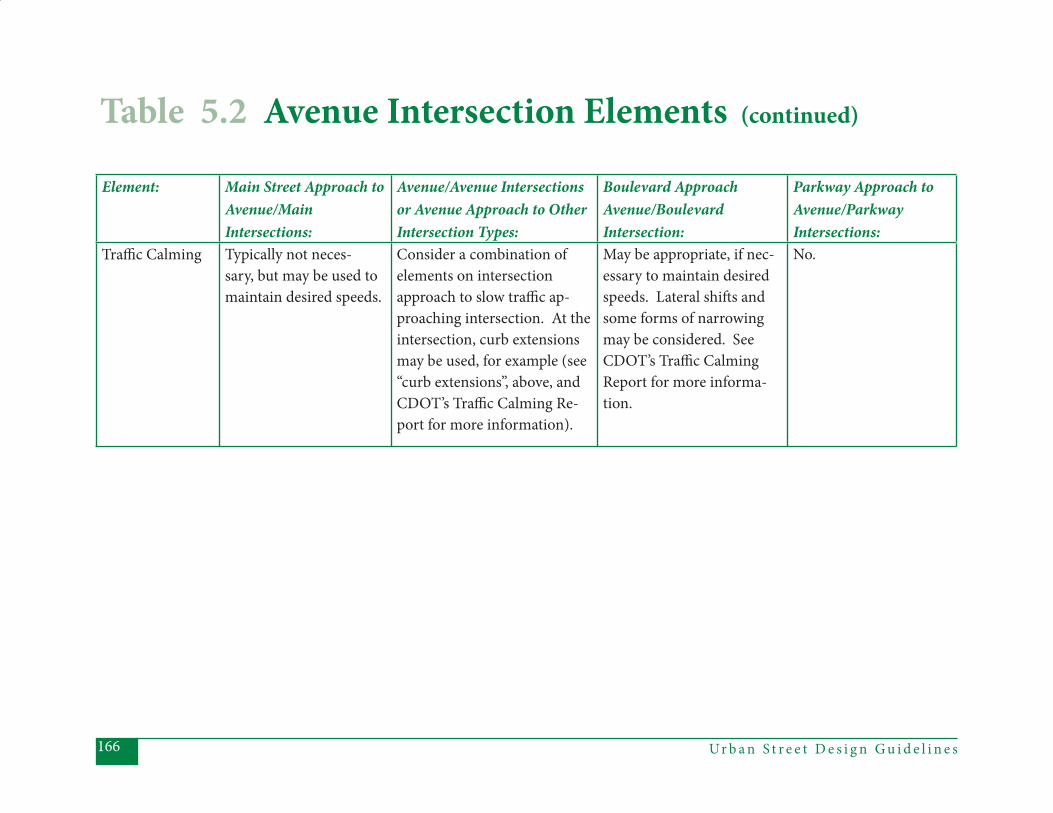
Ur b a n S t r e e t D e s i g n G u i d e l i n e s166
Table 5.2 Avenue Intersection Elements (continued)
Element: Main Street Approach to Avenue/Main Intersections:
Avenue/Avenue Intersections or Avenue Approach to Other Intersection Types:
Boulevard Approach Avenue/Boulevard Intersection:
Parkway Approach to Avenue/Parkway Intersections:
Traffi c Calming Typically not neces-sary, but may be used to maintain desired speeds.
Consider a combination of elements on intersection approach to slow traffi c ap-proaching intersection. At the intersection, curb extensions may be used, for example (see “curb extensions”, above, and CDOT’s Traffi c Calming Re-port for more information).
May be appropriate, if nec-essary to maintain desired speeds. Lateral shift s and some forms of narrowing may be considered. See CDOT’s Traffi c Calming Report for more informa-tion.
No.

167Ur b a n S t r e e t D e s i g n G u i d e l i n e s
Ur b a n S t r e e t D e s i g n G u i d e l i n e s168
Th is section describes the features of all (non-local street) intersections that include at least one Boulevard approach to the intersection. Boulevards serve a wide variety of land uses, while provid-ing important intra-city travel functions. Special care must be taken at Boulevard intersections with Main Streets and Avenues, because the higher speeds and volumes of the Boulevard must not overwhelm the pedestrian orientation of the Main Street and the desire for modal balance of the Avenue. Th is is an impor-tant point because the design solutions for the Boulevard approaches may be in confl ict with the design requirements for the other approaches for these types of intersections.
General Intent: (1) Pedestrians and cyclists will be provided with a safe LOS at Boule- vard intersections.
(2) Designing for pedestrians will be particularly important where Boule- vards intersect Main Streets and Avenues.
(3) Boulevard intersections are likely to be fairly large, increasing the impor- tance of aesthetics in their design.
Th e following table provides guidance in applying design elements to diff erent types of Boulevard intersections. Th e column headings refer to the various possible types of approach legs. Th e “Boulevard Approach” column should be used to assess Boulevard-to-Boulevard intersections, as well as the Boulevard approach to any of the other intersection types (Boulevard-to-Main, Boulevard-to-Avenue, and Boulevard-to-Parkway). For a discussion of Boulevards intersecting Local Streets, see “Local Street Intersec-tions”, Section 5.5.
5.3 Boulevard Intersections
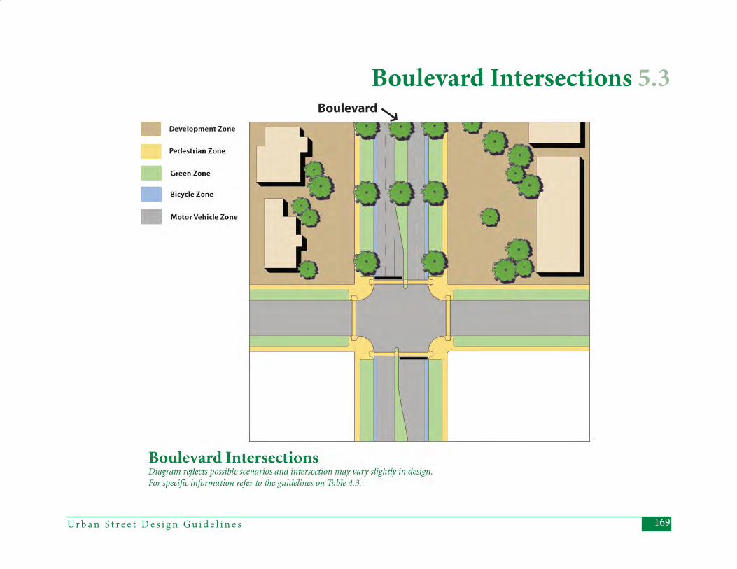
169Ur b a n S t r e e t D e s i g n G u i d e l i n e s
Boulevard Intersections 5.3Boulevard

Ur b a n S t r e e t D e s i g n G u i d e l i n e s170
Element: Main Street Approach to Blvd/Main Intersections:
Avenue Approach to Blvd/Avenue Intersections:
Blvd/Blvd Intersections or Blvd. Approach to Other Intersection Types:
Parkway Approach to Blvd/Parkway Intersections:
Level of Service (LOS):
• Pedestrian LOS B for the entire Blvd/Main intersection.
LOS B for the entire Blvd/Avenue intersection.
LOS C for the entire Blvd/Blvd intersection.
LOS D for the entire Blvd/Parkway intersection.
• Bicycle LOS B for the entire Blvd/Main intersection, using the average LOS value of only the Blvd approaches (see Appendix A for de-tails).
LOS B for the entire Blvd/Ave intersection.
LOS C for the entire Blvd/Blvd intersection.
LOS C/D for the entire Blvd/Parkway intersection.
• Motor Vehicle V/C Th reshold
.95, for two consecutive AM or PM hours, for the entire Blvd/Main intersec-tion.
.95, for two consecutive AM or PM hours, for the entire Blvd/Ave intersection.
.95, for BOTH one AM and one PM hour, for the entire Blvd/Blvd intersection.
.95, for BOTH one AM and one PM hour, for the entire Blvd/Parkway intersection.
Median Atypical, but allowable under special circum-stances. (Chapter 4, Sec-tion 4.1)
Atypical. When provided, should be a minimum width of 6’ (for pedestrian refuge) at intersections (8’ preferred if the Avenue approaches have land uses likely to generate heavy pedestrian traffi c).
Should be provided, with a minimum width of 6’ (for pedestrian refuge) at the intersection. 8’ mini-mum at Main Streets and at Avenues if the Avenue approaches have land uses likely to generate pedestrian traffi c across the Boulevard.
Yes, preferably 9’ wide at the intersection, 6’ minimum (for pedestrian refuge).
Table 5.3 Boulevard Intersection Elements
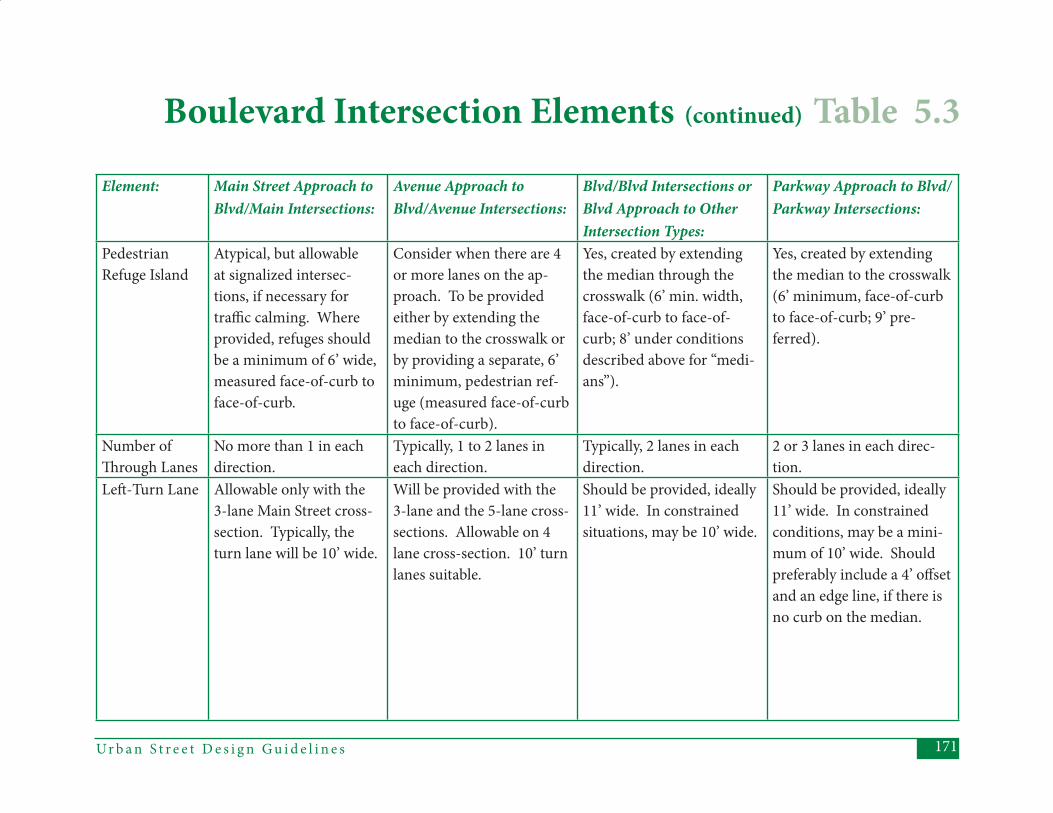
171Ur b a n S t r e e t D e s i g n G u i d e l i n e s
Element: Main Street Approach to Blvd/Main Intersections:
Avenue Approach to Blvd/Avenue Intersections:
Blvd/Blvd Intersections or Blvd Approach to Other Intersection Types:
Parkway Approach to Blvd/Parkway Intersections:
PedestrianRefuge Island
Atypical, but allowable at signalized intersec-tions, if necessary for traffi c calming. Where provided, refuges should be a minimum of 6’ wide, measured face-of-curb to face-of-curb.
Consider when there are 4 or more lanes on the ap-proach. To be provided either by extending the median to the crosswalk or by providing a separate, 6’ minimum, pedestrian ref-uge (measured face-of-curb to face-of-curb).
Yes, created by extending the median through the crosswalk (6’ min. width, face-of-curb to face-of-curb; 8’ under conditions described above for “medi-ans”).
Yes, created by extending the median to the crosswalk (6’ minimum, face-of-curb to face-of-curb; 9’ pre-ferred).
Number of Th rough Lanes
No more than 1 in each direction.
Typically, 1 to 2 lanes in each direction.
Typically, 2 lanes in each direction.
2 or 3 lanes in each direc-tion.
Left -Turn Lane Allowable only with the 3-lane Main Street cross-section. Typically, the turn lane will be 10’ wide.
Will be provided with the 3-lane and the 5-lane cross-sections. Allowable on 4 lane cross-section. 10’ turn lanes suitable.
Should be provided, ideally 11’ wide. In constrained situations, may be 10’ wide.
Should be provided, ideally 11’ wide. In constrained conditions, may be a mini-mum of 10’ wide. Should preferably include a 4’ off set and an edge line, if there is no curb on the median.
Boulevard Intersection Elements (continued) Table 5.3
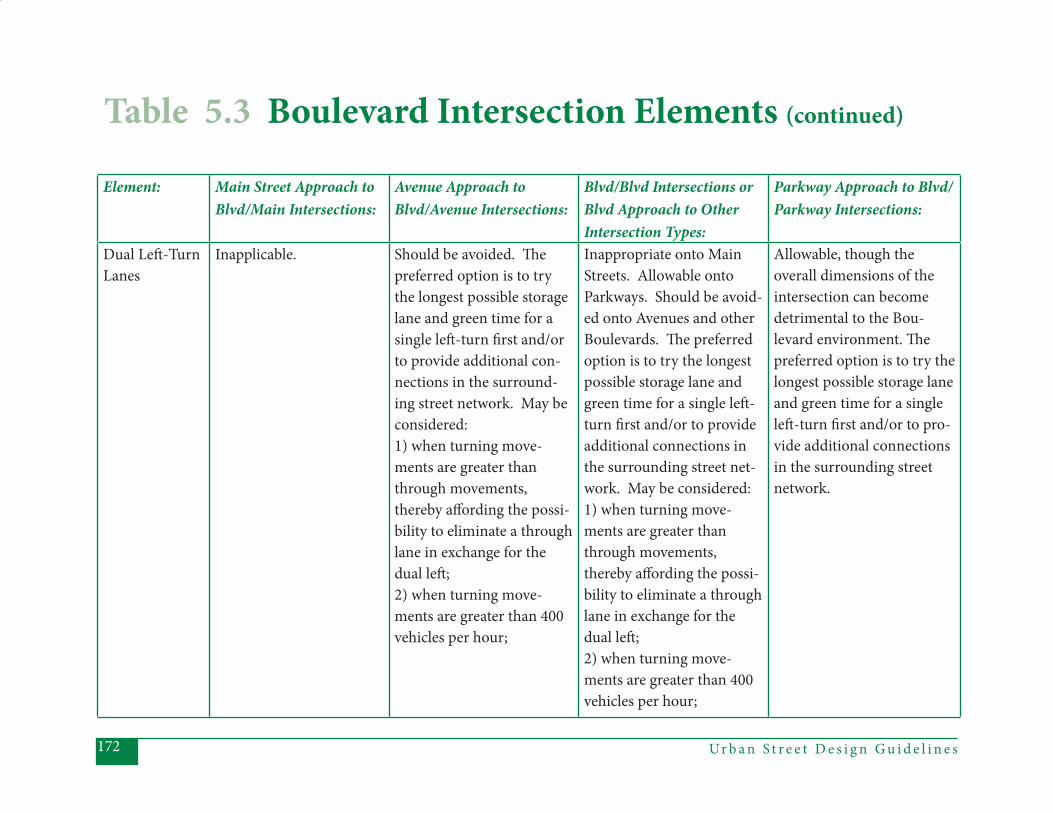
Ur b a n S t r e e t D e s i g n G u i d e l i n e s172
Element: Main Street Approach to Blvd/Main Intersections:
Avenue Approach to Blvd/Avenue Intersections:
Blvd/Blvd Intersections or Blvd Approach to Other Intersection Types:
Parkway Approach to Blvd/Parkway Intersections:
Dual Left -Turn Lanes
Inapplicable. Should be avoided. Th e preferred option is to try the longest possible storage lane and green time for a single left -turn fi rst and/or to provide additional con-nections in the surround-ing street network. May be considered: 1) when turning move-ments are greater than through movements, thereby aff ording the possi-bility to eliminate a through lane in exchange for the dual left ; 2) when turning move-ments are greater than 400 vehicles per hour;
Inappropriate onto Main Streets. Allowable onto Parkways. Should be avoid-ed onto Avenues and other Boulevards. Th e preferred option is to try the longest possible storage lane and green time for a single left -turn fi rst and/or to provide additional connections in the surrounding street net-work. May be considered: 1) when turning move-ments are greater than through movements, thereby aff ording the possi-bility to eliminate a through lane in exchange for the dual left ; 2) when turning move-ments are greater than 400 vehicles per hour;
Allowable, though the overall dimensions of the intersection can become detrimental to the Bou-levard environment. Th e preferred option is to try the longest possible storage lane and green time for a single left -turn fi rst and/or to pro-vide additional connections in the surrounding street network.
Table 5.3 Boulevard Intersection Elements (continued)
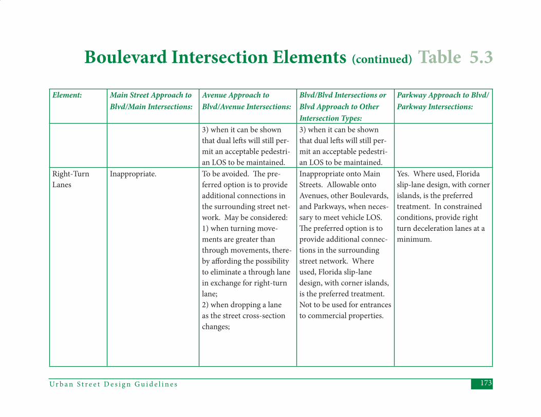
173Ur b a n S t r e e t D e s i g n G u i d e l i n e s
Element: Main Street Approach to Blvd/Main Intersections:
Avenue Approach to Blvd/Avenue Intersections:
Blvd/Blvd Intersections or Blvd Approach to Other Intersection Types:
Parkway Approach to Blvd/Parkway Intersections:
3) when it can be shown that dual left s will still per-mit an acceptable pedestri-an LOS to be maintained.
3) when it can be shown that dual left s will still per-mit an acceptable pedestri-an LOS to be maintained.
Right-Turn Lanes
Inappropriate. To be avoided. Th e pre-ferred option is to provide additional connections in the surrounding street net-work. May be considered: 1) when turning move-ments are greater than through movements, there-by aff ording the possibility to eliminate a through lane in exchange for right-turn lane; 2) when dropping a lane as the street cross-section changes;
Inappropriate onto Main Streets. Allowable onto Avenues, other Boulevards, and Parkways, when neces-sary to meet vehicle LOS. Th e preferred option is to provide additional connec-tions in the surrounding street network. Where used, Florida slip-lane design, with corner islands, is the preferred treatment. Not to be used for entrances to commercial properties.
Yes. Where used, Florida slip-lane design, with corner islands, is the preferred treatment. In constrained conditions, provide right turn deceleration lanes at a minimum.
Boulevard Intersection Elements (continued) Table 5.3
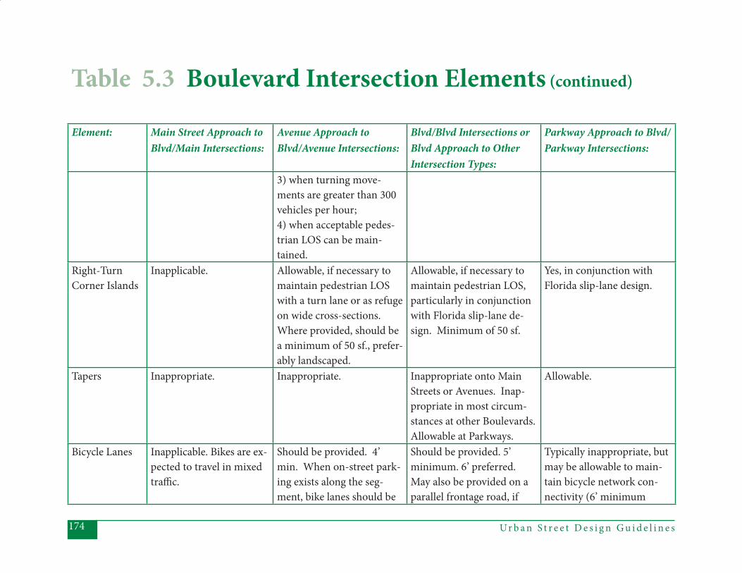
Ur b a n S t r e e t D e s i g n G u i d e l i n e s174
Element: Main Street Approach to Blvd/Main Intersections:
Avenue Approach to Blvd/Avenue Intersections:
Blvd/Blvd Intersections or Blvd Approach to Other Intersection Types:
Parkway Approach to Blvd/Parkway Intersections:
3) when turning move-ments are greater than 300 vehicles per hour; 4) when acceptable pedes-trian LOS can be main-tained.
Right-Turn Corner Islands
Inapplicable. Allowable, if necessary to maintain pedestrian LOS with a turn lane or as refuge on wide cross-sections. Where provided, should be a minimum of 50 sf., prefer-ably landscaped.
Allowable, if necessary to maintain pedestrian LOS, particularly in conjunction with Florida slip-lane de-sign. Minimum of 50 sf.
Yes, in conjunction with Florida slip-lane design.
Tapers Inappropriate. Inappropriate. Inappropriate onto Main Streets or Avenues. Inap-propriate in most circum-stances at other Boulevards. Allowable at Parkways.
Allowable.
Bicycle Lanes Inapplicable. Bikes are ex-pected to travel in mixed traffi c.
Should be provided. 4’ min. When on-street park-ing exists along the seg-ment, bike lanes should be
Should be provided. 5’ minimum. 6’ preferred. May also be provided on a parallel frontage road, if
Typically inappropriate, but may be allowable to main-tain bicycle network con-nectivity (6’ minimum
Table 5.3 Boulevard Intersection Elements (continued)

175Ur b a n S t r e e t D e s i g n G u i d e l i n e s
Element: Main Street Approach to Blvd/Main Intersections:
Avenue Approach to Blvd/Avenue Intersections:
Blvd/Blvd Intersections or Blvd Approach to Other Intersection Types:
Parkway Approach to Blvd/Parkway Intersections:
5’ minimum with 6’ pre-ferred. Th ere should be a “receiving” lane on the op-posite side of the intersec-tion. Otherwise, the bike lane should be dropped just prior to the actual intersec-tion, to allow the cyclist to safely merge. Th e bike lane should never be located to the right of an exclusive vehicle turning lane.
that increases bicycle LOS. Th ere should be a “receiv-ing” lane on the opposite side of the intersection. Otherwise, the bike lane should be dropped just prior to the actual intersec-tion to allow the cyclist to safely merge. Th e bike lane should never be located to the right of an exclusive vehicle turning lane.
for adequate separation from high-speed traffi c). Preferred option is to have separate facility outside of right-of-way or on parallel local streets.
Curb Extensions
Should be provided, at same width as the on-street parking, except at far-side bus stops with high service frequencies.
Should be provided (at the same width as the on-street parking) where full-time on-street parking exists along the segment, except at far-side bus stops on 2-3 lane cross-sections.
Inappropriate. Prohibited.
Bus Stops: Typically located at far side of intersection.
Typically located at far side of intersection.
Typically located at far side of intersection.
Typically located at off -street lots or stops. Far side stops preferred at intersec-tions.
Boulevard Intersection Elements (continued) Table 5.3
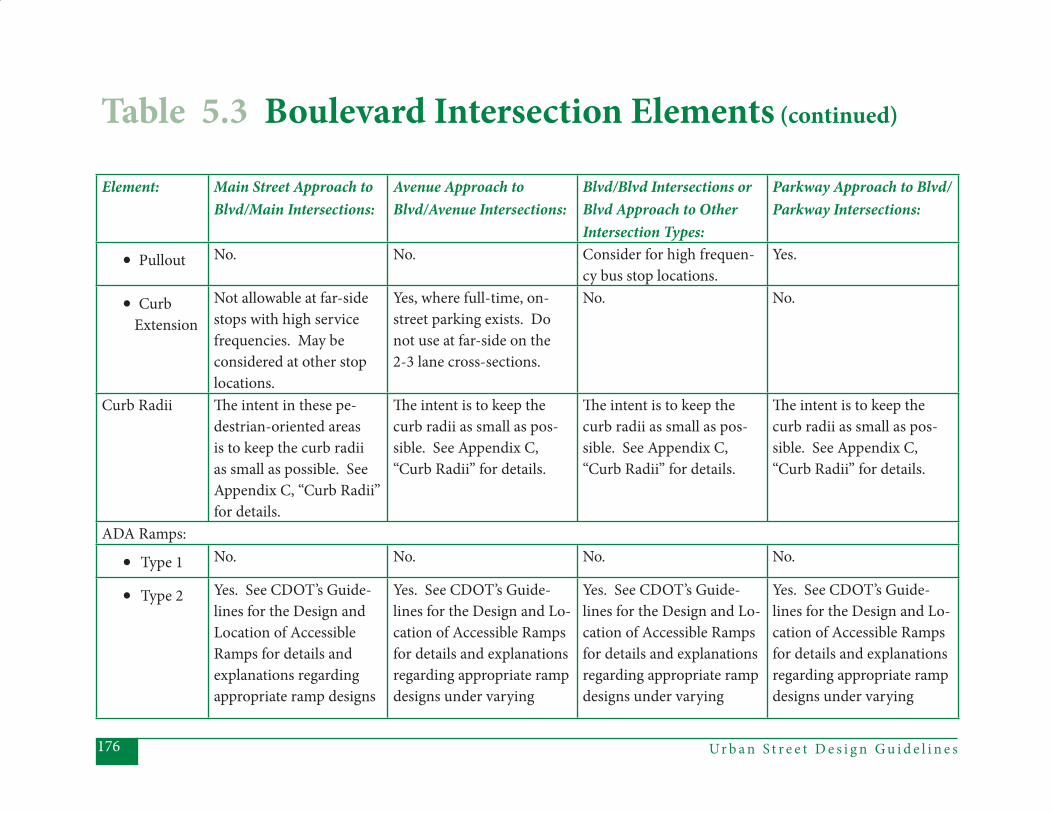
Ur b a n S t r e e t D e s i g n G u i d e l i n e s176
Element: Main Street Approach to Blvd/Main Intersections:
Avenue Approach to Blvd/Avenue Intersections:
Blvd/Blvd Intersections or Blvd Approach to Other Intersection Types:
Parkway Approach to Blvd/Parkway Intersections:
• Pullout No. No. Consider for high frequen-cy bus stop locations.
Yes.
• Curb Extension
Not allowable at far-side stops with high service frequencies. May be considered at other stop locations.
Yes, where full-time, on-street parking exists. Do not use at far-side on the 2-3 lane cross-sections.
No. No.
Curb Radii Th e intent in these pe-destrian-oriented areas is to keep the curb radii as small as possible. See Appendix C, “Curb Radii” for details.
Th e intent is to keep the curb radii as small as pos-sible. See Appendix C, “Curb Radii” for details.
Th e intent is to keep the curb radii as small as pos-sible. See Appendix C, “Curb Radii” for details.
Th e intent is to keep the curb radii as small as pos-sible. See Appendix C, “Curb Radii” for details.
ADA Ramps:
• Type 1 No. No. No. No.
• Type 2 Yes. See CDOT’s Guide-lines for the Design and Location of Accessible Ramps for details and explanations regarding appropriate ramp designs
Yes. See CDOT’s Guide-lines for the Design and Lo-cation of Accessible Ramps for details and explanations regarding appropriate ramp designs under varying
Yes. See CDOT’s Guide-lines for the Design and Lo-cation of Accessible Ramps for details and explanations regarding appropriate ramp designs under varying
Yes. See CDOT’s Guide-lines for the Design and Lo-cation of Accessible Ramps for details and explanations regarding appropriate ramp designs under varying
Table 5.3 Boulevard Intersection Elements (continued)
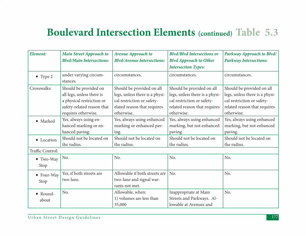
177Ur b a n S t r e e t D e s i g n G u i d e l i n e s
Element: Main Street Approach to Blvd/Main Intersections:
Avenue Approach to Blvd/Avenue Intersections:
Blvd/Blvd Intersections or Blvd Approach to Other Intersection Types:
Parkway Approach to Blvd/Parkway Intersections:
• Type 2 under varying circum-stances.
circumstances. circumstances. circumstances.
Crosswalks: Should be provided on all legs, unless there is a physical restriction or safety-related reason that requires otherwise.
Should be provided on all legs, unless there is a physi-cal restriction or safety-elated reason that requires otherwise.
Should be provided on all legs, unless there is a physi-cal restriction or safety-related reason that requires otherwise.
Should be provided on all legs, unless there is a physi-cal restriction or safety-related reason that requires otherwise.
• Marked Yes, always using en-hanced marking or en-hanced paving.
Yes, always using enhanced marking or enhanced pav-ing.
Yes, always using enhanced marking, but not enhanced paving.
Yes, always using enhanced marking, but not enhanced paving.
• Location Should not be located on the radius.
Should not be located on the radius.
Should not be located on the radius.
Should not be located on the radius.
Traffi c Control:
• Two-Way Stop
No. No. No. No.
• Four-Way Stop
Yes, if both streets are two-lane.
Allowable if both streets are two-lane and signal war-rants not met.
No. No.
• Round- about
No. Allowable, when: 1) volumes are less than 35,000
Inappropriate at Main Streets and Parkways. Al-lowable at Avenues and
No.
Boulevard Intersection Elements (continued) Table 5.3
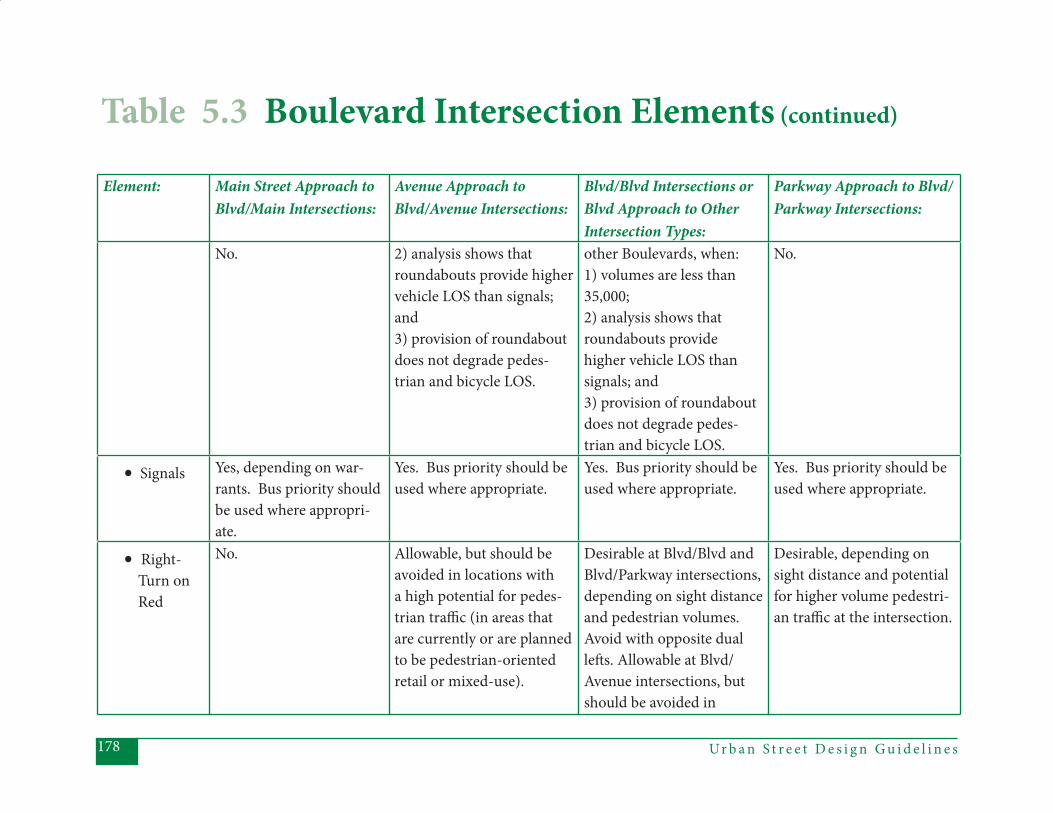
Ur b a n S t r e e t D e s i g n G u i d e l i n e s178
Element: Main Street Approach to Blvd/Main Intersections:
Avenue Approach to Blvd/Avenue Intersections:
Blvd/Blvd Intersections or Blvd Approach to Other Intersection Types:
Parkway Approach to Blvd/Parkway Intersections:
No. 2) analysis shows that roundabouts provide higher vehicle LOS than signals; and 3) provision of roundabout does not degrade pedes-trian and bicycle LOS.
other Boulevards, when: 1) volumes are less than 35,000; 2) analysis shows that roundabouts provide higher vehicle LOS than signals; and 3) provision of roundabout does not degrade pedes-trian and bicycle LOS.
No.
• Signals Yes, depending on war-rants. Bus priority should be used where appropri-ate.
Yes. Bus priority should be used where appropriate.
Yes. Bus priority should be used where appropriate.
Yes. Bus priority should be used where appropriate.
• Right- Turn on Red
No. Allowable, but should be avoided in locations with a high potential for pedes-trian traffi c (in areas that are currently or are planned to be pedestrian-oriented retail or mixed-use).
Desirable at Blvd/Blvd and Blvd/Parkway intersections, depending on sight distance and pedestrian volumes. Avoid with opposite dual left s. Allowable at Blvd/Avenue intersections, but should be avoided in
Desirable, depending on sight distance and potential for higher volume pedestri-an traffi c at the intersection.
Table 5.3 Boulevard Intersection Elements (continued)
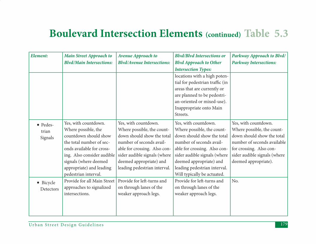
179Ur b a n S t r e e t D e s i g n G u i d e l i n e s
Element: Main Street Approach to Blvd/Main Intersections:
Avenue Approach to Blvd/Avenue Intersections:
Blvd/Blvd Intersections or Blvd Approach to Other Intersection Types:
Parkway Approach to Blvd/Parkway Intersections:
locations with a high poten-tial for pedestrian traffi c (in areas that are currently or are planned to be pedestri-an-oriented or mixed-use). Inappropriate onto Main Streets.
• Pedes- trian
Signals
Yes, with countdown. Where possible, the countdown should show the total number of sec-onds available for cross-ing. Also consider audible signals (where deemed appropriate) and leading pedestrian interval.
Yes, with countdown. Where possible, the count-down should show the total number of seconds avail-able for crossing. Also con-sider audible signals (where deemed appropriate) and leading pedestrian interval.
Yes, with countdown. Where possible, the count-down should show the total number of seconds avail-able for crossing. Also con-sider audible signals (where deemed appropriate) and leading pedestrian interval. Will typically be actuated.
Yes, with countdown. Where possible, the count-down should show the total number of seconds available for crossing. Also con-sider audible signals (where deemed appropriate).
• Bicycle Detectors
Provide for all Main Street approaches to signalized intersections.
Provide for left -turns and on through lanes of the weaker approach legs.
Provide for left -turns and on through lanes of the weaker approach legs.
No.
Boulevard Intersection Elements (continued) Table 5.3
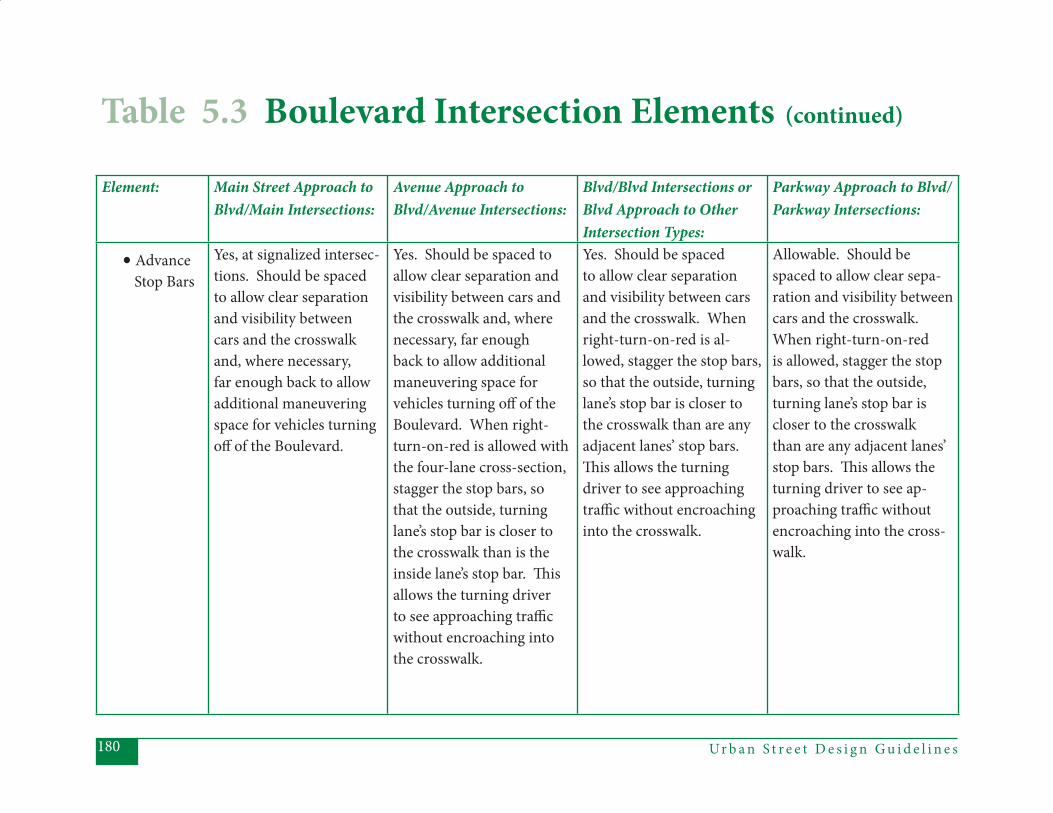
Ur b a n S t r e e t D e s i g n G u i d e l i n e s180
Element: Main Street Approach to Blvd/Main Intersections:
Avenue Approach to Blvd/Avenue Intersections:
Blvd/Blvd Intersections or Blvd Approach to Other Intersection Types:
Parkway Approach to Blvd/Parkway Intersections:
• Advance Stop Bars
Yes, at signalized intersec-tions. Should be spaced to allow clear separation and visibility between cars and the crosswalk and, where necessary, far enough back to allow additional maneuvering space for vehicles turning off of the Boulevard.
Yes. Should be spaced to allow clear separation and visibility between cars and the crosswalk and, where necessary, far enough back to allow additional maneuvering space for vehicles turning off of the Boulevard. When right-turn-on-red is allowed with the four-lane cross-section, stagger the stop bars, so that the outside, turning lane’s stop bar is closer to the crosswalk than is the inside lane’s stop bar. Th is allows the turning driver to see approaching traffi c without encroaching into the crosswalk.
Yes. Should be spaced to allow clear separation and visibility between cars and the crosswalk. When right-turn-on-red is al-lowed, stagger the stop bars, so that the outside, turning lane’s stop bar is closer to the crosswalk than are any adjacent lanes’ stop bars. Th is allows the turning driver to see approaching traffi c without encroaching into the crosswalk.
Allowable. Should be spaced to allow clear sepa-ration and visibility between cars and the crosswalk. When right-turn-on-red is allowed, stagger the stop bars, so that the outside, turning lane’s stop bar is closer to the crosswalk than are any adjacent lanes’ stop bars. Th is allows the turning driver to see ap-proaching traffi c without encroaching into the cross-walk.
Table 5.3 Boulevard Intersection Elements (continued)
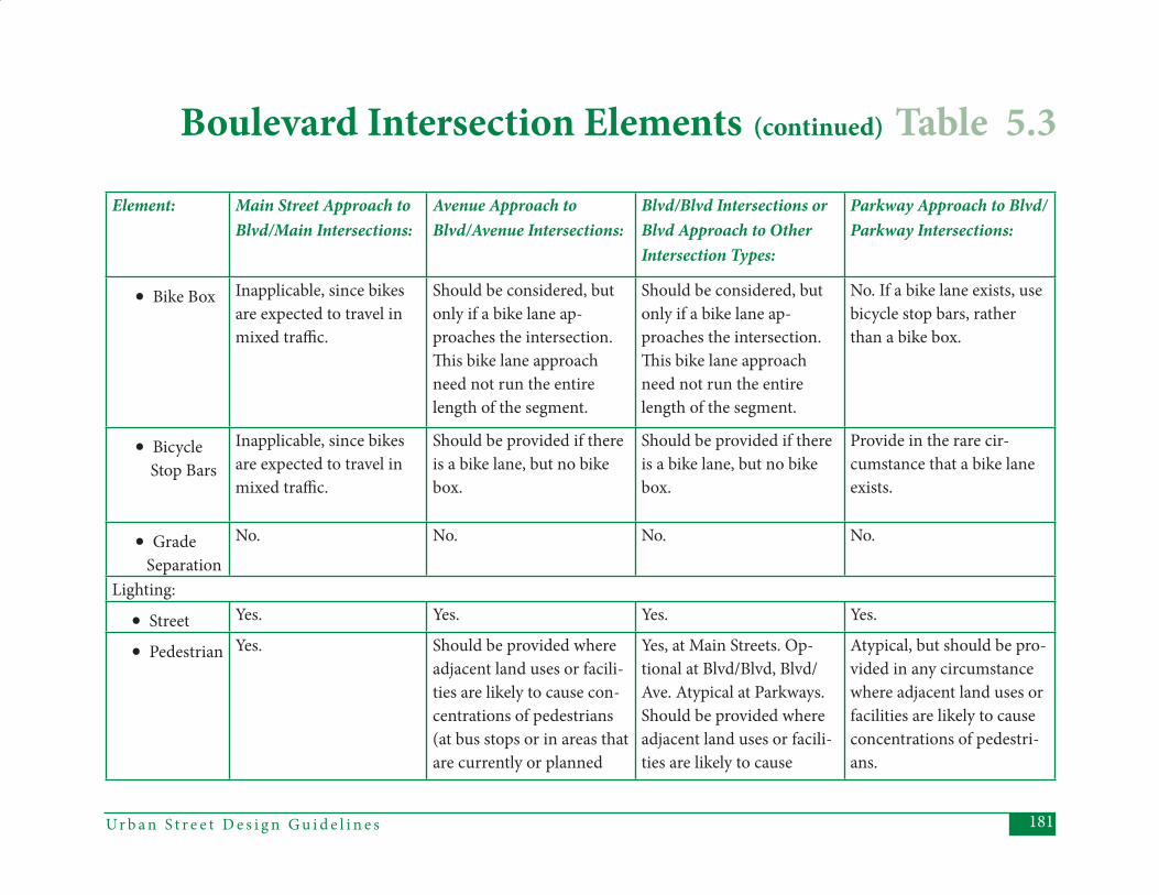
181Ur b a n S t r e e t D e s i g n G u i d e l i n e s
Element: Main Street Approach to Blvd/Main Intersections:
Avenue Approach to Blvd/Avenue Intersections:
Blvd/Blvd Intersections or Blvd Approach to Other Intersection Types:
Parkway Approach to Blvd/Parkway Intersections:
• Bike Box Inapplicable, since bikes are expected to travel in mixed traffi c.
Should be considered, but only if a bike lane ap-proaches the intersection. Th is bike lane approach need not run the entire length of the segment.
Should be considered, but only if a bike lane ap-proaches the intersection. Th is bike lane approach need not run the entire length of the segment.
No. If a bike lane exists, use bicycle stop bars, rather than a bike box.
• Bicycle Stop Bars
Inapplicable, since bikes are expected to travel in mixed traffi c.
Should be provided if there is a bike lane, but no bike box.
Should be provided if there is a bike lane, but no bike box.
Provide in the rare cir-cumstance that a bike lane exists.
• Grade Separation
No. No. No. No.
Lighting:
• Street Yes. Yes. Yes. Yes.
• Pedestrian Yes. Should be provided where adjacent land uses or facili-ties are likely to cause con-centrations of pedestrians (at bus stops or in areas that are currently or planned
Yes, at Main Streets. Op-tional at Blvd/Blvd, Blvd/Ave. Atypical at Parkways. Should be provided where adjacent land uses or facili-ties are likely to cause
Atypical, but should be pro-vided in any circumstance where adjacent land uses or facilities are likely to cause concentrations of pedestri-ans.
Boulevard Intersection Elements (continued) Table 5.3
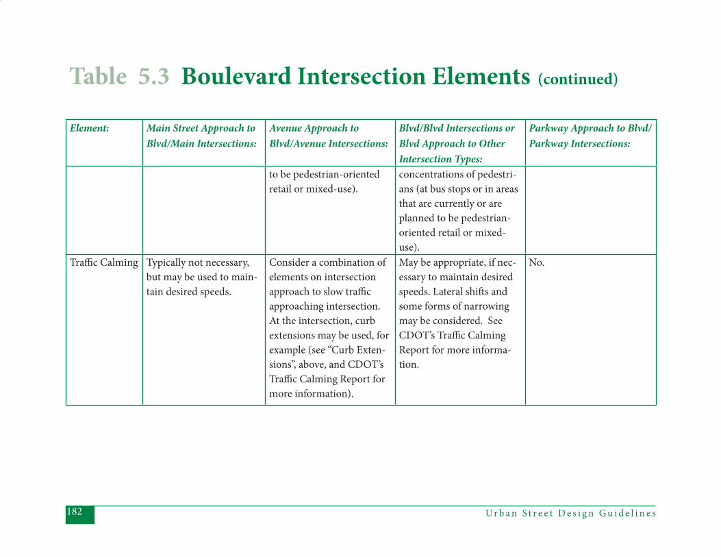
Ur b a n S t r e e t D e s i g n G u i d e l i n e s182
Table 5.3 Boulevard Intersection Elements (continued)
Element: Main Street Approach to Blvd/Main Intersections:
Avenue Approach to Blvd/Avenue Intersections:
Blvd/Blvd Intersections or Blvd Approach to Other Intersection Types:
Parkway Approach to Blvd/Parkway Intersections:
to be pedestrian-oriented retail or mixed-use).
concentrations of pedestri-ans (at bus stops or in areas that are currently or are planned to be pedestrian-oriented retail or mixed-use).
Traffi c Calming Typically not necessary, but may be used to main-tain desired speeds.
Consider a combination of elements on intersection approach to slow traffi c approaching intersection. At the intersection, curb extensions may be used, for example (see “Curb Exten-sions”, above, and CDOT’s Traffi c Calming Report for more information).
May be appropriate, if nec-essary to maintain desired speeds. Lateral shift s and some forms of narrowing may be considered. See CDOT’s Traffi c Calming Report for more informa-tion.
No.

183Ur b a n S t r e e t D e s i g n G u i d e l i n e s
Ur b a n S t r e e t D e s i g n G u i d e l i n e s184
Th is section describes the features of all (non-local street) intersections that include at least one Parkway approach to the intersection. Parkways serve as high-volume, relatively high-speed in-tra-urban thoroughfares. Adjacent land uses are assumed to be auto-oriented in both type and design, with access con-trol much more prevalent than on any other street type. Parkways may inter-sect with all other street types, except Main Streets. While the basic design of a Parkway intersection is intended to serve high volumes of traffi c, some design ele-ments may be adjusted to refl ect the type of street the Parkway is intersecting.
General Intent:(1) Providing motor vehicle capacity and reducing travel delay is a major de-
sign goal for Parkway intersections.
(2) Safety for all users is another impor- tant goal, even though motor vehicle level-of-service is emphasized.
(3) Land uses that would generate large numbers of pedestrians wanting to cross the Parkway should be limited near Parkway intersections.
Th e following table provides guidance in applying design elements to diff erent types of Parkway intersections. Th e col-umn headings refer to the various pos-sible types of approach legs. Th e “Park-way Approach” column should be used to assess Parkway-to-Parkway intersections, as well as the Parkway approach to any of the other intersection types (Parkway-to-Avenue, and Parkway-to-Boulevard). For a discussion of Parkways intersecting Local Streets, see “Local Street Intersec-tions”, Section 5.5.
5.4 Parkway Intersections
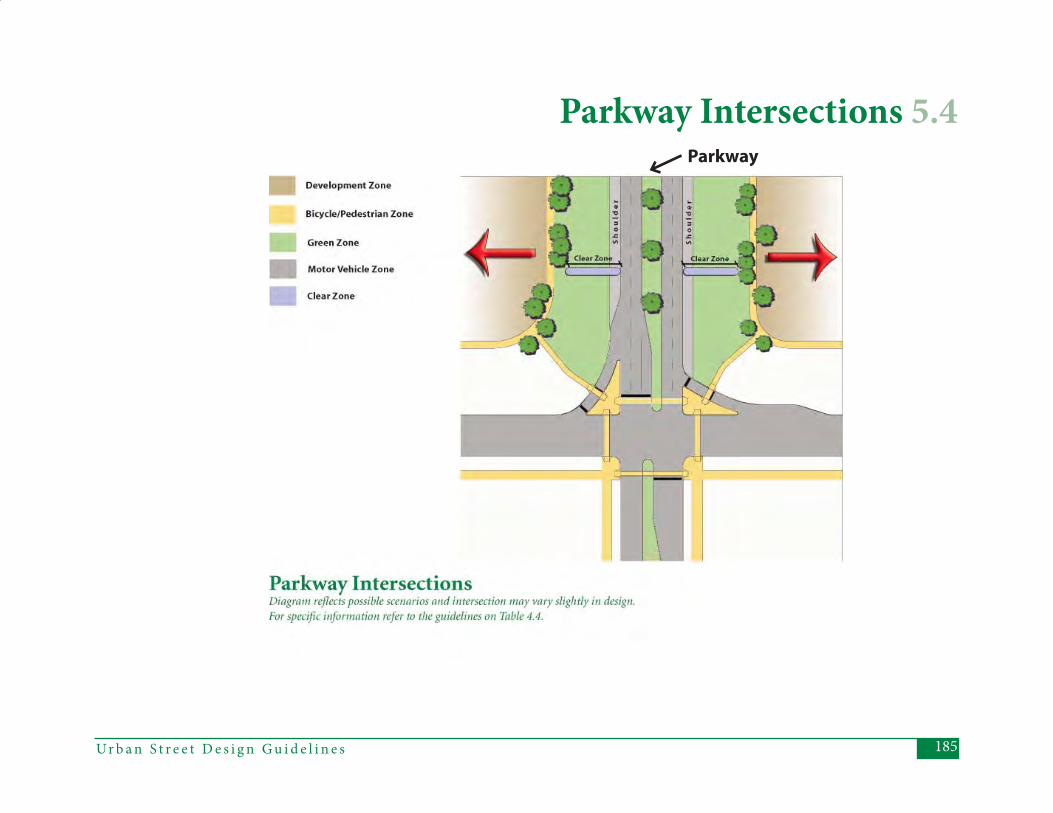
185Ur b a n S t r e e t D e s i g n G u i d e l i n e s
Parkway Intersections 5.4Parkway
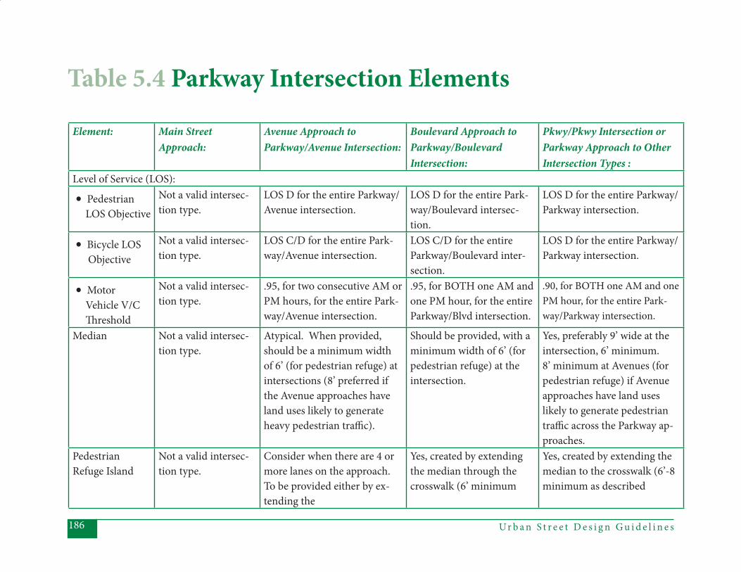
Ur b a n S t r e e t D e s i g n G u i d e l i n e s186
Element: Main Street Approach:
Avenue Approach to Parkway/Avenue Intersection:
Boulevard Approach to Parkway/BoulevardIntersection:
Pkwy/Pkwy Intersection or Parkway Approach to Other Intersection Types :
Level of Service (LOS):
• Pedestrian LOS Objective
Not a valid intersec-tion type.
LOS D for the entire Parkway/Avenue intersection.
LOS D for the entire Park-way/Boulevard intersec-tion.
LOS D for the entire Parkway/Parkway intersection.
• Bicycle LOS Objective
Not a valid intersec-tion type.
LOS C/D for the entire Park-way/Avenue intersection.
LOS C/D for the entire Parkway/Boulevard inter-section.
LOS D for the entire Parkway/Parkway intersection.
• Motor Vehicle V/C Th reshold
Not a valid intersec-tion type.
.95, for two consecutive AM or PM hours, for the entire Park-way/Avenue intersection.
.95, for BOTH one AM and one PM hour, for the entire Parkway/Blvd intersection.
.90, for BOTH one AM and one PM hour, for the entire Park-way/Parkway intersection.
Median Not a valid intersec-tion type.
Atypical. When provided, should be a minimum width of 6’ (for pedestrian refuge) at intersections (8’ preferred if the Avenue approaches have land uses likely to generate heavy pedestrian traffi c).
Should be provided, with a minimum width of 6’ (for pedestrian refuge) at the intersection.
Yes, preferably 9’ wide at the intersection, 6’ minimum. 8’ minimum at Avenues (for pedestrian refuge) if Avenue approaches have land uses likely to generate pedestrian traffi c across the Parkway ap-proaches.
Pedestrian Refuge Island
Not a valid intersec-tion type.
Consider when there are 4 or more lanes on the approach. To be provided either by ex-tending the
Yes, created by extending the median through the crosswalk (6’ minimum
Yes, created by extending the median to the crosswalk (6’-8 minimum as described
Table 5.4 Parkway Intersection Elements

187Ur b a n S t r e e t D e s i g n G u i d e l i n e s
Element: Main Street Approach:
Avenue Approach to Parkway/Avenue Intersection:
Boulevard Approach to Parkway/BoulevardIntersection:
Pkwy/Pkwy Intersection or Parkway Approach to Other Intersection Types :
median to the crosswalk or by providing a separate, 6’ minimum, pedestrian refuge, measured face-of-curb to face-of-curb.
width, face-of-curb to face-of-curb).
above for medians, 9’ pre-ferred).
Number of Th rough Lanes
Not a valid intersec-tion type.
Typically, 1 to 2 lanes in each direction.
Typically 2 lanes in each direction.
2 or 3 lanes in each direction.
Left -Turn Lane Not a valid intersec-tion type.
Will be provided with the 3-lane or the 5-lane cross-sections. Allowable on 4 lane cross-section. 10’ turn lanes suitable.
Should be provided, ideally 11’ wide. In constrained situations, may be 10’ wide.
Should be provided, ideally 11’ wide. In constrained con-ditions, may be a minimum of 10’ wide. Should preferably include a 4’ off set and an edge line, if there is no curb on the median.
Dual Left -Turn Lanes
Not a valid intersec-tion type.
Should be avoided. Th e pre-ferred option is to try the lon-gest possible storage lane and green time for a single left -turn fi rst and/or to provide additional connections in the surrounding street network. May be considered:
Allowable. Th e preferred option is to try the longest possible storage lane and green time for a single left -turn fi rst and/or to provide additional connections in the surrounding street network.
Allowable, though the overall dimensions of the intersection can become detrimental to the Avenue or Boulevard environ-ments. Th e preferred option is to try the longest possible storage lane and green time for
Parkway Intersection Elements (continued) Table 5.4
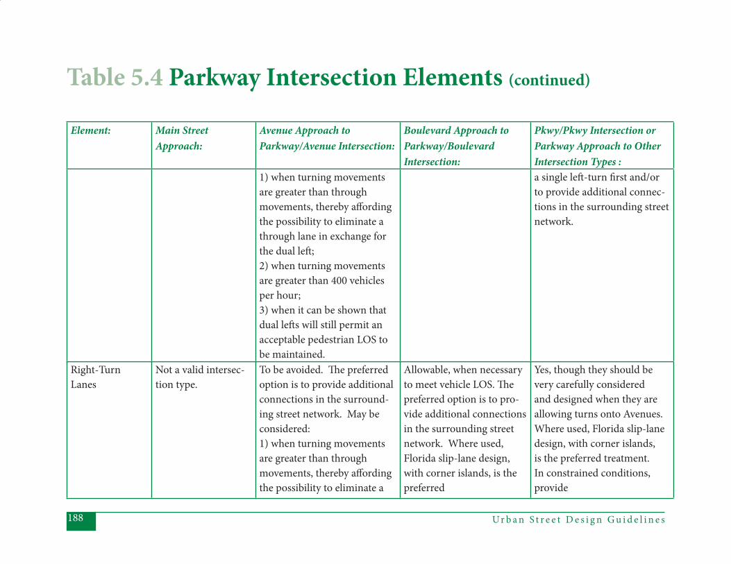
Ur b a n S t r e e t D e s i g n G u i d e l i n e s188
Element: Main Street Approach:
Avenue Approach to Parkway/Avenue Intersection:
Boulevard Approach to Parkway/BoulevardIntersection:
Pkwy/Pkwy Intersection or Parkway Approach to Other Intersection Types :
1) when turning movements are greater than through movements, thereby aff ording the possibility to eliminate a through lane in exchange for the dual left ; 2) when turning movements are greater than 400 vehicles per hour; 3) when it can be shown that dual left s will still permit an acceptable pedestrian LOS to be maintained.
a single left -turn fi rst and/or to provide additional connec-tions in the surrounding street network.
Right-Turn Lanes
Not a valid intersec-tion type.
To be avoided. Th e preferred option is to provide additional connections in the surround-ing street network. May be considered: 1) when turning movements are greater than through movements, thereby aff ording the possibility to eliminate a
Allowable, when necessary to meet vehicle LOS. Th e preferred option is to pro-vide additional connections in the surrounding street network. Where used, Florida slip-lane design, with corner islands, is the preferred
Yes, though they should be very carefully considered and designed when they are allowing turns onto Avenues. Where used, Florida slip-lane design, with corner islands, is the preferred treatment. In constrained conditions, provide
Table 5.4 Parkway Intersection Elements (continued)
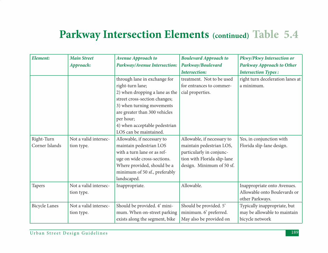
189Ur b a n S t r e e t D e s i g n G u i d e l i n e s
Element: Main Street Approach:
Avenue Approach to Parkway/Avenue Intersection:
Boulevard Approach to Parkway/BoulevardIntersection:
Pkwy/Pkwy Intersection or Parkway Approach to Other Intersection Types :
through lane in exchange for right-turn lane; 2) when dropping a lane as the street cross-section changes; 3) when turning movements are greater than 300 vehicles per hour; 4) when acceptable pedestrian LOS can be maintained.
treatment. Not to be used for entrances to commer-cial properties.
right turn deceleration lanes at a minimum.
Right-Turn Corner Islands
Not a valid intersec-tion type.
Allowable, if necessary to maintain pedestrian LOS with a turn lane or as ref-uge on wide cross-sections. Where provided, should be a minimum of 50 sf., preferably landscaped.
Allowable, if necessary to maintain pedestrian LOS, particularly in conjunc-tion with Florida slip-lane design. Minimum of 50 sf.
Yes, in conjunction with Florida slip-lane design.
Tapers Not a valid intersec-tion type.
Inappropriate. Allowable. Inappropriate onto Avenues. Allowable onto Boulevards or other Parkways.
Bicycle Lanes Not a valid intersec-tion type.
Should be provided. 4’ mini-mum. When on-street parking exists along the segment, bike
Should be provided. 5’ minimum. 6’ preferred. May also be provided on
Typically inappropriate, but may be allowable to maintain bicycle network
Parkway Intersection Elements (continued) Table 5.4
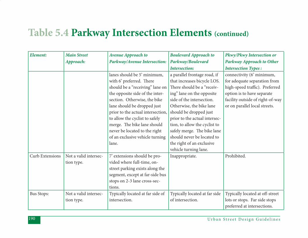
Ur b a n S t r e e t D e s i g n G u i d e l i n e s190
Element: Main Street Approach:
Avenue Approach to Parkway/Avenue Intersection:
Boulevard Approach to Parkway/BoulevardIntersection:
Pkwy/Pkwy Intersection or Parkway Approach to Other Intersection Types :
lanes should be 5’ minimum, with 6’ preferred. Th ere should be a “receiving” lane on the opposite side of the inter-section. Otherwise, the bike lane should be dropped just prior to the actual intersection, to allow the cyclist to safely merge. Th e bike lane should never be located to the right of an exclusive vehicle turning lane.
a parallel frontage road, if that increases bicycle LOS. Th ere should be a “receiv-ing” lane on the opposite side of the intersection. Otherwise, the bike lane should be dropped just prior to the actual intersec-tion, to allow the cyclist to safely merge. Th e bike lane should never be located to the right of an exclusive vehicle turning lane.
connectivity (6’ minimum, for adequate separation from high-speed traffi c). Preferred option is to have separate facility outside of right-of-way or on parallel local streets.
Curb Extensions Not a valid intersec-tion type.
7’ extensions should be pro-vided where full-time, on-street parking exists along the segment, except at far-side bus stops on 2-3 lane cross-sec-tions.
Inappropriate. Prohibited.
Bus Stops: Not a valid intersec-tion type.
Typically located at far side of intersection.
Typically located at far side of intersection.
Typically located at off -street lots or stops. Far side stops preferred at intersections.
Table 5.4 Parkway Intersection Elements (continued)
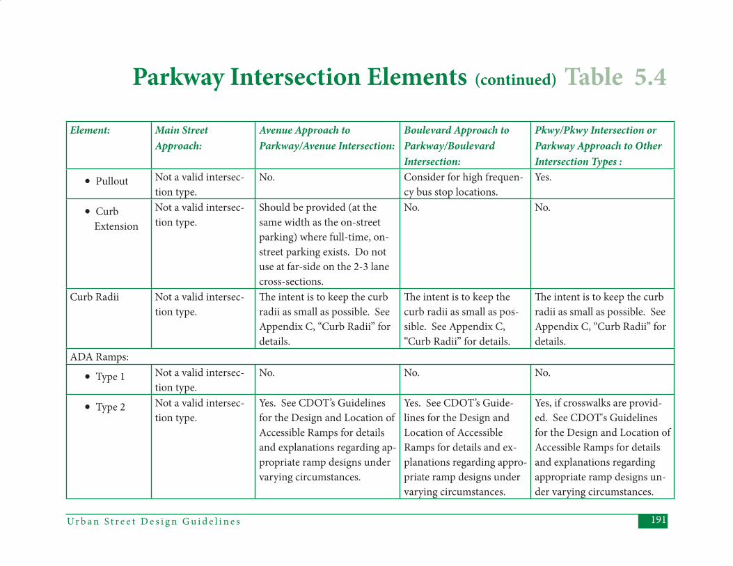
191Ur b a n S t r e e t D e s i g n G u i d e l i n e s
Element: Main Street Approach:
Avenue Approach to Parkway/Avenue Intersection:
Boulevard Approach to Parkway/BoulevardIntersection:
Pkwy/Pkwy Intersection or Parkway Approach to Other Intersection Types :
• Pullout Not a valid intersec-tion type.
No. Consider for high frequen-cy bus stop locations.
Yes.
• Curb Extension
Not a valid intersec-tion type.
Should be provided (at the same width as the on-street parking) where full-time, on-street parking exists. Do not use at far-side on the 2-3 lane cross-sections.
No. No.
Curb Radii Not a valid intersec-tion type.
Th e intent is to keep the curb radii as small as possible. See Appendix C, “Curb Radii” for details.
Th e intent is to keep the curb radii as small as pos-sible. See Appendix C, “Curb Radii” for details.
Th e intent is to keep the curb radii as small as possible. See Appendix C, “Curb Radii” for details.
ADA Ramps:
• Type 1 Not a valid intersec-tion type.
No. No. No.
• Type 2 Not a valid intersec-tion type.
Yes. See CDOT’s Guidelines for the Design and Location of Accessible Ramps for details and explanations regarding ap-propriate ramp designs under varying circumstances.
Yes. See CDOT’s Guide-lines for the Design and Location of Accessible Ramps for details and ex-planations regarding appro-priate ramp designs under varying circumstances.
Yes, if crosswalks are provid-ed. See CDOT's Guidelines for the Design and Location of Accessible Ramps for details and explanations regarding appropriate ramp designs un-der varying circumstances.
Parkway Intersection Elements (continued) Table 5.4
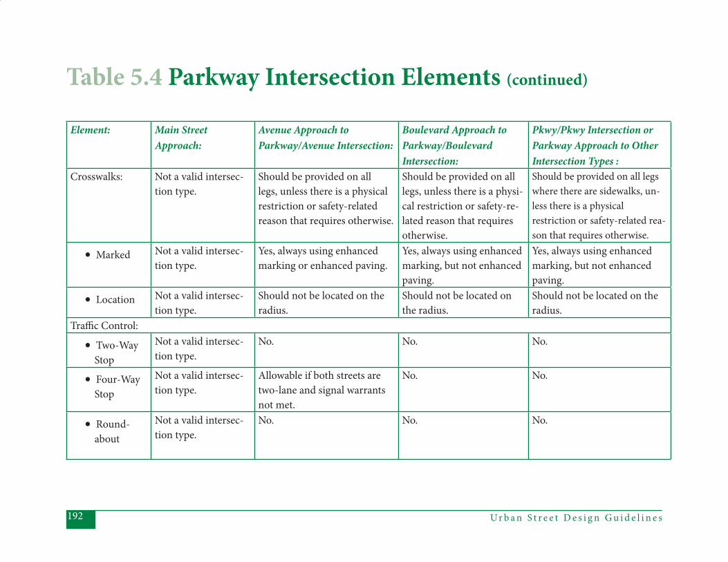
Ur b a n S t r e e t D e s i g n G u i d e l i n e s192
Element: Main Street Approach:
Avenue Approach to Parkway/Avenue Intersection:
Boulevard Approach to Parkway/BoulevardIntersection:
Pkwy/Pkwy Intersection or Parkway Approach to Other Intersection Types :
Crosswalks: Not a valid intersec-tion type.
Should be provided on all legs, unless there is a physical restriction or safety-related reason that requires otherwise.
Should be provided on all legs, unless there is a physi-cal restriction or safety-re-lated reason that requires otherwise.
Should be provided on all legs where there are sidewalks, un-less there is a physical restriction or safety-related rea-son that requires otherwise.
• Marked Not a valid intersec-tion type.
Yes, always using enhanced marking or enhanced paving.
Yes, always using enhanced marking, but not enhanced paving.
Yes, always using enhanced marking, but not enhanced paving.
• Location Not a valid intersec-tion type.
Should not be located on the radius.
Should not be located on the radius.
Should not be located on the radius.
Traffi c Control:
• Two-Way Stop
Not a valid intersec-tion type.
No. No. No.
• Four-Way Stop
Not a valid intersec-tion type.
Allowable if both streets are two-lane and signal warrants not met.
No. No.
• Round- about
Not a valid intersec-tion type.
No. No. No.
Table 5.4 Parkway Intersection Elements (continued)
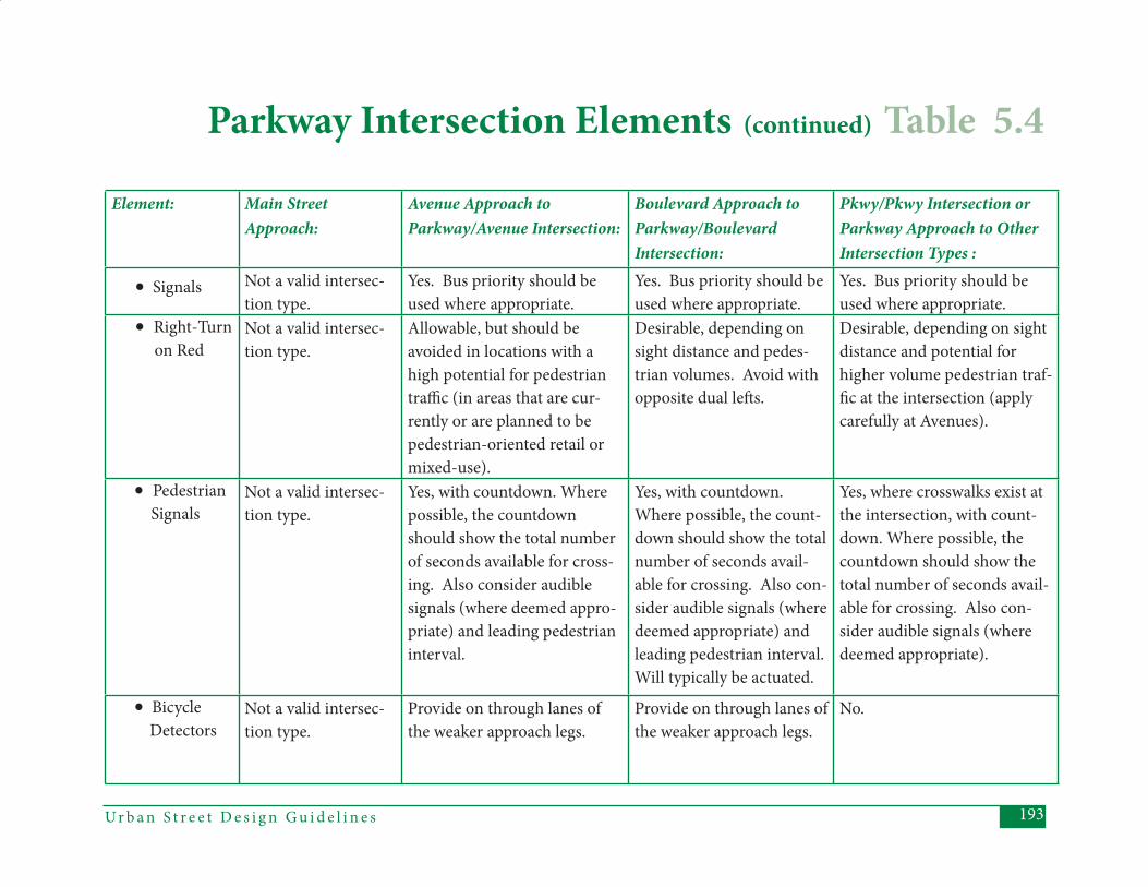
193Ur b a n S t r e e t D e s i g n G u i d e l i n e s
Element: Main Street Approach:
Avenue Approach to Parkway/Avenue Intersection:
Boulevard Approach to Parkway/BoulevardIntersection:
Pkwy/Pkwy Intersection or Parkway Approach to Other Intersection Types :
• Signals Not a valid intersec-tion type.
Yes. Bus priority should be used where appropriate.
Yes. Bus priority should be used where appropriate.
Yes. Bus priority should be used where appropriate.
• Right-Turn on Red
Not a valid intersec-tion type.
Allowable, but should be avoided in locations with a high potential for pedestrian traffi c (in areas that are cur-rently or are planned to be pedestrian-oriented retail or mixed-use).
Desirable, depending on sight distance and pedes-trian volumes. Avoid with opposite dual left s.
Desirable, depending on sight distance and potential for higher volume pedestrian traf-fi c at the intersection (apply carefully at Avenues).
• Pedestrian Signals
Not a valid intersec-tion type.
Yes, with countdown. Where possible, the countdown should show the total number of seconds available for cross-ing. Also consider audible signals (where deemed appro-priate) and leading pedestrian interval.
Yes, with countdown. Where possible, the count-down should show the total number of seconds avail-able for crossing. Also con-sider audible signals (where deemed appropriate) and leading pedestrian interval. Will typically be actuated.
Yes, where crosswalks exist at the intersection, with count-down. Where possible, the countdown should show the total number of seconds avail-able for crossing. Also con-sider audible signals (where deemed appropriate).
• Bicycle Detectors
Not a valid intersec-tion type.
Provide on through lanes of the weaker approach legs.
Provide on through lanes of the weaker approach legs.
No.
Parkway Intersection Elements (continued) Table 5.4
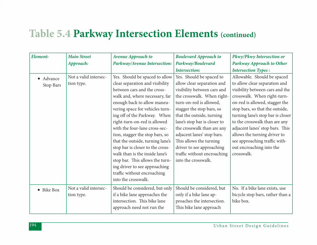
Ur b a n S t r e e t D e s i g n G u i d e l i n e s194
Element: Main Street Approach:
Avenue Approach to Parkway/Avenue Intersection:
Boulevard Approach to Parkway/BoulevardIntersection:
Pkwy/Pkwy Intersection or Parkway Approach to Other Intersection Types :
• Advance Stop Bars
Not a valid intersec-tion type.
Yes. Should be spaced to allow clear separation and visibility between cars and the cross-walk and, where necessary, far enough back to allow maneu-vering space for vehicles turn-ing off of the Parkway. When right-turn-on-red is allowed with the four-lane cross-sec-tion, stagger the stop bars, so that the outside, turning lane’s stop bar is closer to the cross-walk than is the inside lane’s stop bar. Th is allows the turn-ing driver to see approaching traffi c without encroaching into the crosswalk.
Yes. Should be spaced to allow clear separation and visibility between cars and the crosswalk. When right-turn-on-red is allowed, stagger the stop bars, so that the outside, turning lane’s stop bar is closer to the crosswalk than are any adjacent lanes’ stop bars. Th is allows the turning driver to see approaching traffi c without encroaching into the crosswalk.
Allowable. Should be spaced to allow clear separation and visibility between cars and the crosswalk. When right-turn-on-red is allowed, stagger the stop bars, so that the outside, turning lane’s stop bar is closer to the crosswalk than are any adjacent lanes’ stop bars. Th is allows the turning driver to see approaching traffi c with-out encroaching into the crosswalk.
• Bike Box Not a valid intersec-tion type.
Should be considered, but only if a bike lane approaches the intersection. Th is bike lane approach need not run the
Should be considered, but only if a bike lane ap-proaches the intersection. Th is bike lane approach
No. If a bike lane exists, use bicycle stop bars, rather than a bike box.
Table 5.4 Parkway Intersection Elements (continued)
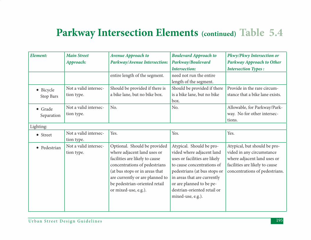
195Ur b a n S t r e e t D e s i g n G u i d e l i n e s
Element: Main Street Approach:
Avenue Approach to Parkway/Avenue Intersection:
Boulevard Approach to Parkway/BoulevardIntersection:
Pkwy/Pkwy Intersection or Parkway Approach to Other Intersection Types :
entire length of the segment. need not run the entire length of the segment.
• Bicycle Stop Bars
Not a valid intersec-tion type.
Should be provided if there is a bike lane, but no bike box.
Should be provided if there is a bike lane, but no bike box.
Provide in the rare circum-stance that a bike lane exists.
• Grade Separation
Not a valid intersec-tion type.
No. No. Allowable, for Parkway/Park-way. No for other intersec-tions.
Lighting:
• Street Not a valid intersec-tion type.
Yes. Yes. Yes.
• Pedestrian Not a valid intersec-tion type.
Optional. Should be provided where adjacent land uses or facilities are likely to cause concentrations of pedestrians (at bus stops or in areas that are currently or are planned to be pedestrian-oriented retail or mixed-use, e.g.).
Atypical. Should be pro-vided where adjacent land uses or facilities are likely to cause concentrations of pedestrians (at bus stops or in areas that are currently or are planned to be pe-destrian-oriented retail or mixed-use, e.g.).
Atypical, but should be pro-vided in any circumstance where adjacent land uses or facilities are likely to cause concentrations of pedestrians.
Parkway Intersection Elements (continued) Table 5.4
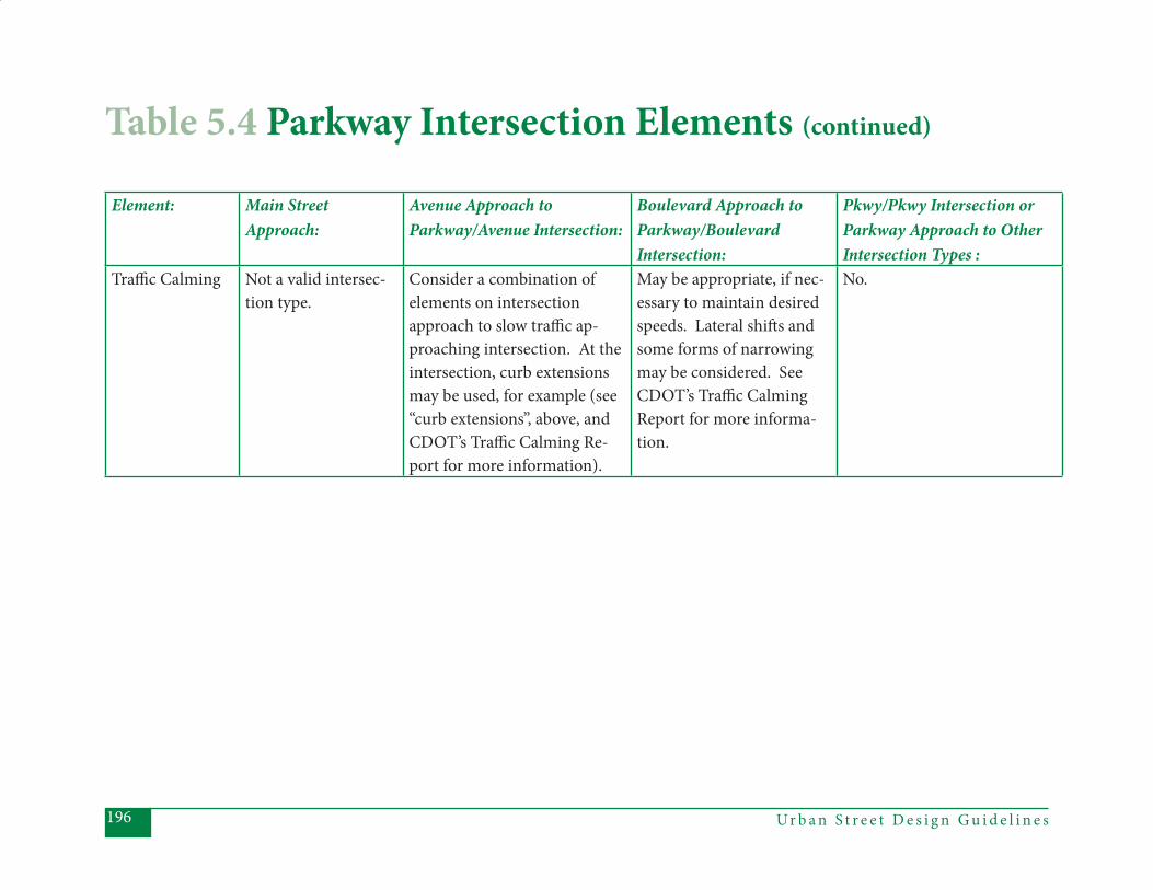
Ur b a n S t r e e t D e s i g n G u i d e l i n e s196
Element: Main Street Approach:
Avenue Approach to Parkway/Avenue Intersection:
Boulevard Approach to Parkway/BoulevardIntersection:
Pkwy/Pkwy Intersection or Parkway Approach to Other Intersection Types :
Traffi c Calming Not a valid intersec-tion type.
Consider a combination of elements on intersection approach to slow traffi c ap-proaching intersection. At the intersection, curb extensions may be used, for example (see “curb extensions”, above, and CDOT’s Traffi c Calming Re-port for more information).
May be appropriate, if nec-essary to maintain desired speeds. Lateral shift s and some forms of narrowing may be considered. See CDOT’s Traffi c Calming Report for more informa-tion.
No.
Table 5.4 Parkway Intersection Elements (continued)

197Ur b a n S t r e e t D e s i g n G u i d e l i n e s
Ur b a n S t r e e t D e s i g n G u i d e l i n e s198
5.5 Local Street IntersectionsTh ere are three diff erent Local street types (residential, offi ce/commercial, and industrial) and multiple cross-sec-tions for two of those street types (resi-dential and offi ce/commercial). Any of these street types can intersect with any other street type. Intersections between two Local streets should be designed to refl ect the primary function of Local streets - providing access to land uses. Intersections between Local streets and non-local streets should be designed to accommodate the lower volumes and modal balance of a Local street, bal-anced against the higher volumes and wide range of possible functions of the intersecting non-local street. Th e de-sign recommendations for Local streets should be considered more prescriptive than those for non-local streets, particu-larly at Local/Local intersections.
Assumed Conditions:(1) Local streets provide access to specifi c (existing or planned) land uses. Traf- fi c volumes and speeds on Local streets will be low.
(2) Intersections of two Local streets should be designed to maintain low-speed, low-volume conditions simi-lar to or lower than those for Main Streets.
(3) Local streets and their intersections should be designed toward more of a pedestrian orientation than an auto- orientation. Th is is less the case with local industrial streets, where higher volumes of truck traffi c will require some design features that are not as pedestrian-oriented as those of other Local streets.
Th e following table provides guidance in applying design elements to diff erent types of Local intersections. Th e column headings refer to the various possible types of approach legs. Th e “Local Ap-proach” column should be used to assess all Local-to-Local intersections, as well as the Local approach to any of the other intersection types (Local-to-Main, Lo-cal-to-Avenue, Local-to-Boulevard, and Local-to-Parkway).
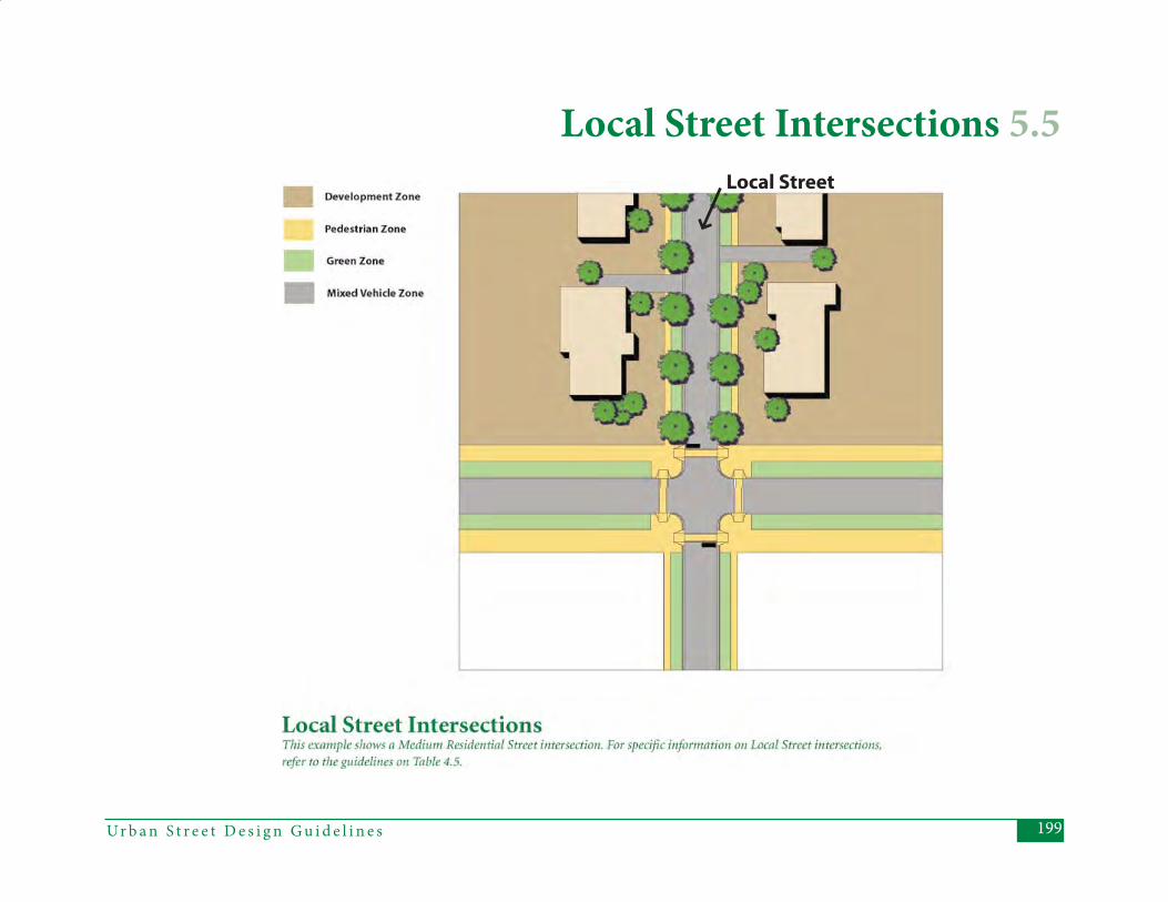
199Ur b a n S t r e e t D e s i g n G u i d e l i n e s
Local Street Intersections 5.5Local Street
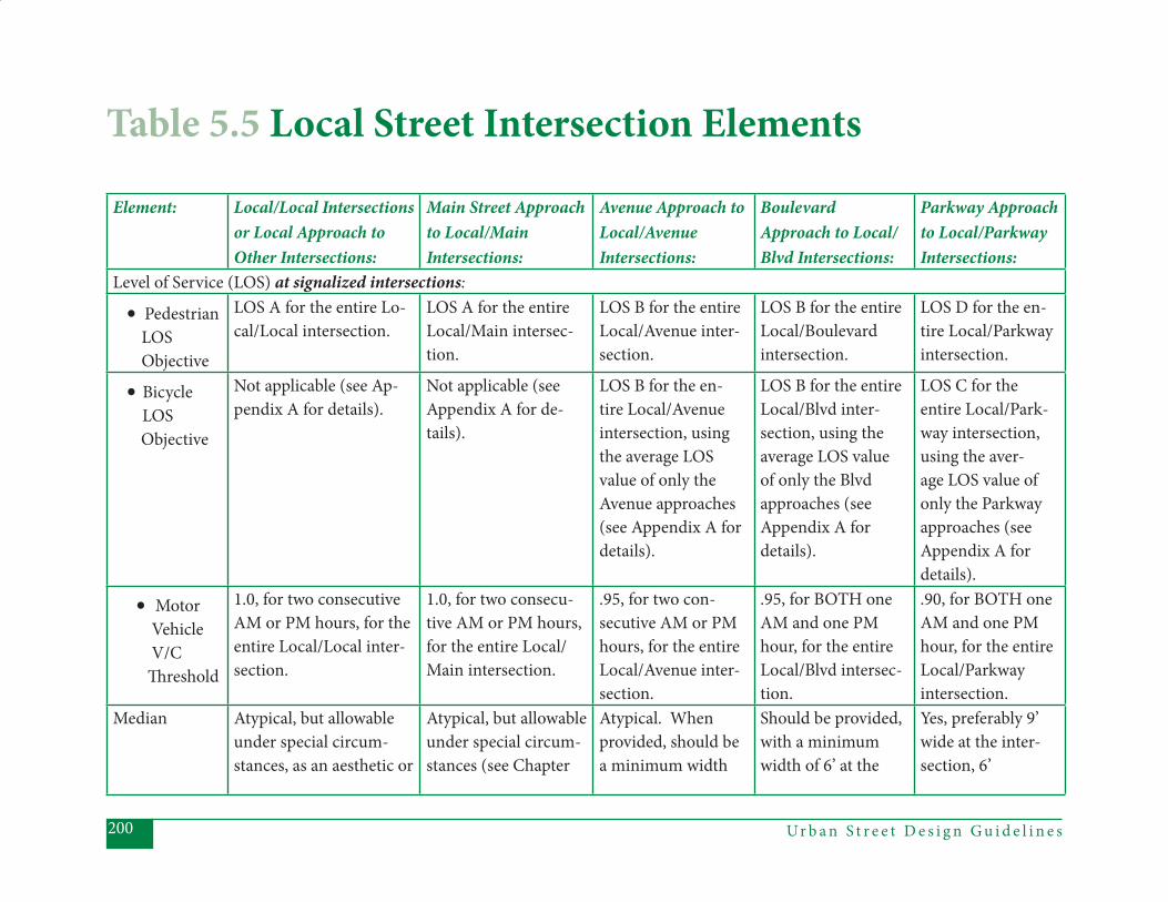
Ur b a n S t r e e t D e s i g n G u i d e l i n e s200
Element: Local/Local Intersections or Local Approach to Other Intersections:
Main Street Approach to Local/Main Intersections:
Avenue Approach to Local/AvenueIntersections:
Boulevard Approach to Local/Blvd Intersections:
Parkway Approach to Local/Parkway Intersections:
Level of Service (LOS) at signalized intersections:
• Pedestrian LOS Objective
LOS A for the entire Lo-cal/Local intersection.
LOS A for the entire Local/Main intersec-tion.
LOS B for the entire Local/Avenue inter-section.
LOS B for the entire Local/Boulevard intersection.
LOS D for the en-tire Local/Parkway intersection.
• Bicycle LOS
Objective
Not applicable (see Ap-pendix A for details).
Not applicable (see Appendix A for de-tails).
LOS B for the en-tire Local/Avenue intersection, using the average LOS value of only the Avenue approaches (see Appendix A for details).
LOS B for the entire Local/Blvd inter-section, using the average LOS value of only the Blvd approaches (see Appendix A for details).
LOS C for the entire Local/Park-way intersection, using the aver-age LOS value of only the Parkway approaches (see Appendix A for details).
• Motor Vehicle V/C Th reshold
1.0, for two consecutive AM or PM hours, for the entire Local/Local inter-section.
1.0, for two consecu-tive AM or PM hours, for the entire Local/Main intersection.
.95, for two con-secutive AM or PM hours, for the entire Local/Avenue inter-section.
.95, for BOTH one AM and one PM hour, for the entire Local/Blvd intersec-tion.
.90, for BOTH one AM and one PM hour, for the entire Local/Parkway intersection.
Median Atypical, but allowable under special circum-stances, as an aesthetic or
Atypical, but allowable under special circum-stances (see Chapter
Atypical. When provided, should be a minimum width
Should be provided, with a minimum width of 6’ at the
Yes, preferably 9’ wide at the inter-section, 6’
Table 5.5 Local Street Intersection Elements
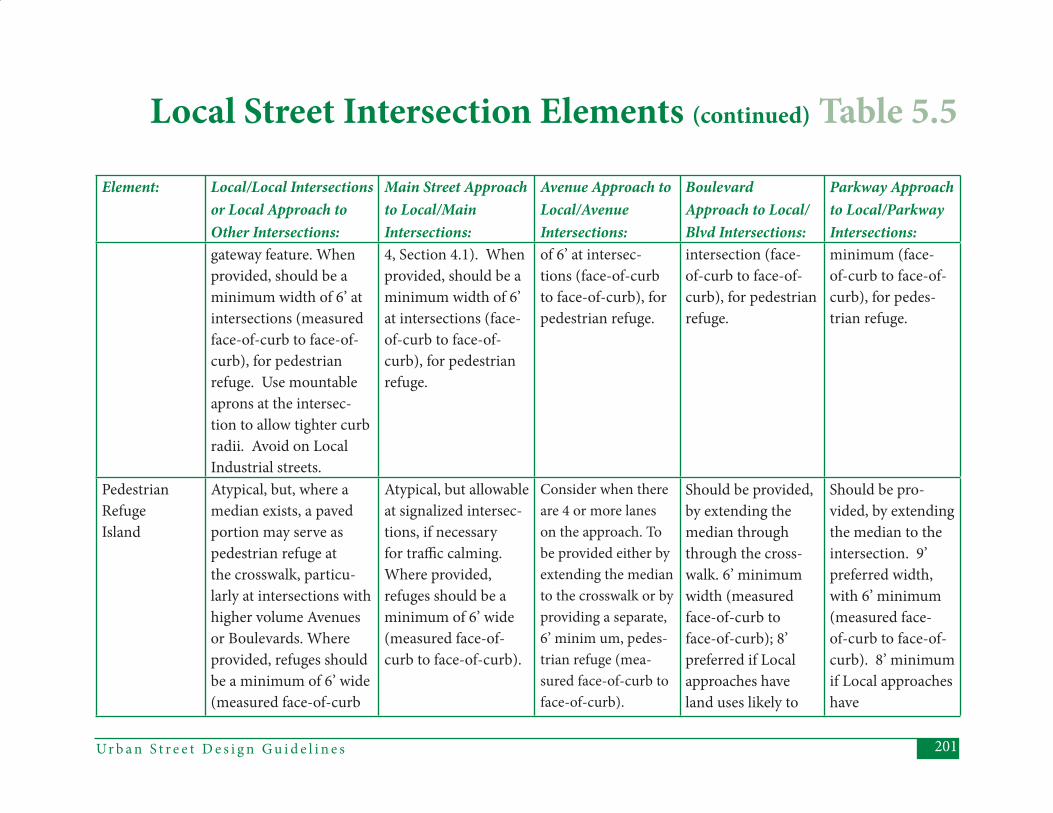
201Ur b a n S t r e e t D e s i g n G u i d e l i n e s
Element: Local/Local Intersections or Local Approach to Other Intersections:
Main Street Approach to Local/Main Intersections:
Avenue Approach to Local/AvenueIntersections:
Boulevard Approach to Local/Blvd Intersections:
Parkway Approach to Local/Parkway Intersections:
gateway feature. When provided, should be a minimum width of 6’ at intersections (measured face-of-curb to face-of-curb), for pedestrian refuge. Use mountable aprons at the intersec-tion to allow tighter curb radii. Avoid on Local Industrial streets.
4, Section 4.1). When provided, should be a minimum width of 6’ at intersections (face-of-curb to face-of-curb), for pedestrian refuge.
of 6’ at intersec-tions (face-of-curb to face-of-curb), for pedestrian refuge.
intersection (face-of-curb to face-of-curb), for pedestrian refuge.
minimum (face-of-curb to face-of-curb), for pedes-trian refuge.
Pedestrian Refuge Island
Atypical, but, where a median exists, a paved portion may serve as pedestrian refuge at the crosswalk, particu-larly at intersections with higher volume Avenues or Boulevards. Where provided, refuges should be a minimum of 6’ wide (measured face-of-curb
Atypical, but allowable at signalized intersec-tions, if necessary for traffi c calming. Where provided, refuges should be a minimum of 6’ wide (measured face-of-curb to face-of-curb).
Consider when there are 4 or more lanes on the approach. To be provided either by extending the median to the crosswalk or by providing a separate, 6’ minim um, pedes-trian refuge (mea-sured face-of-curb to face-of-curb).
Should be provided, by extending the median through through the cross-walk. 6’ minimum width (measured face-of-curb to face-of-curb); 8’ preferred if Local approaches have land uses likely to
Should be pro-vided, by extending the median to the intersection. 9’ preferred width, with 6’ minimum (measured face-of-curb to face-of-curb). 8’ minimum if Local approaches have
Local Street Intersection Elements (continued) Table 5.5
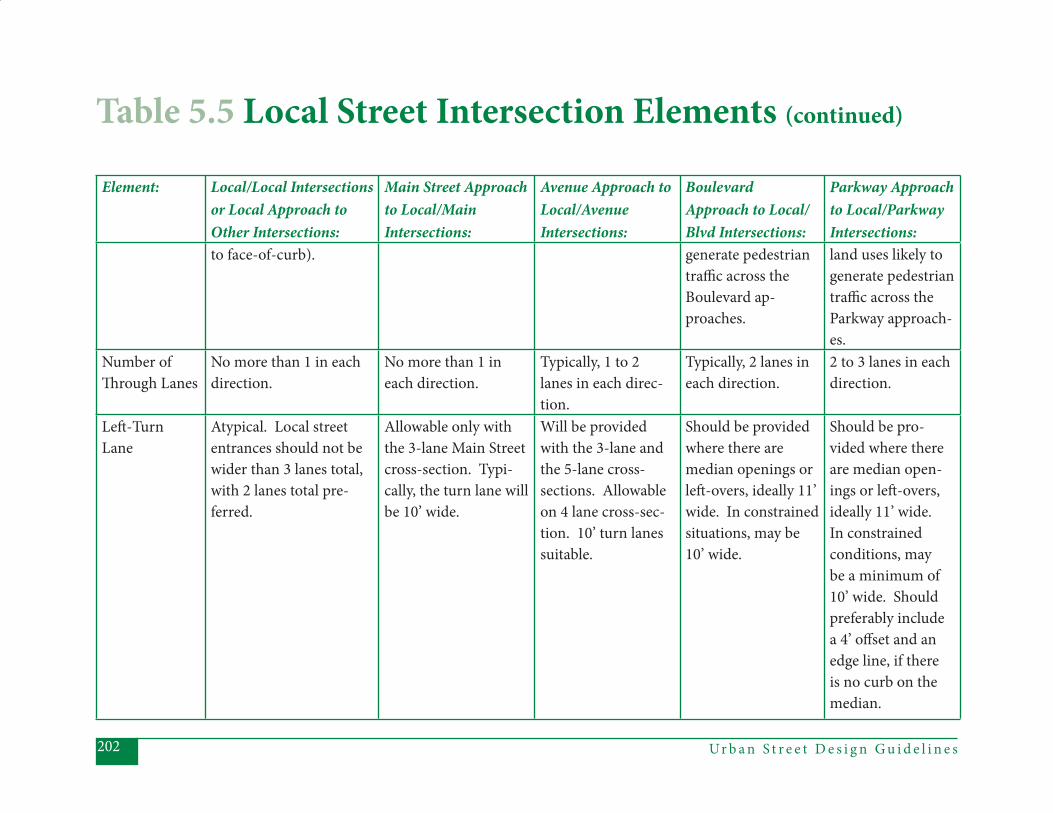
Ur b a n S t r e e t D e s i g n G u i d e l i n e s202
Element: Local/Local Intersections or Local Approach to Other Intersections:
Main Street Approach to Local/Main Intersections:
Avenue Approach to Local/AvenueIntersections:
Boulevard Approach to Local/Blvd Intersections:
Parkway Approach to Local/Parkway Intersections:
to face-of-curb). generate pedestrian traffi c across the Boulevard ap-proaches.
land uses likely to generate pedestrian traffi c across the Parkway approach-es.
Number of Th rough Lanes
No more than 1 in each direction.
No more than 1 in each direction.
Typically, 1 to 2 lanes in each direc-tion.
Typically, 2 lanes in each direction.
2 to 3 lanes in each direction.
Left -TurnLane
Atypical. Local street entrances should not be wider than 3 lanes total, with 2 lanes total pre-ferred.
Allowable only with the 3-lane Main Street cross-section. Typi-cally, the turn lane will be 10’ wide.
Will be provided with the 3-lane and the 5-lane cross-sections. Allowable on 4 lane cross-sec-tion. 10’ turn lanes suitable.
Should be provided where there are median openings or left -overs, ideally 11’ wide. In constrained situations, may be 10’ wide.
Should be pro-vided where there are median open-ings or left -overs, ideally 11’ wide. In constrained conditions, may be a minimum of 10’ wide. Should preferably include a 4’ off set and an edge line, if there is no curb on the median.
Table 5.5 Local Street Intersection Elements (continued)
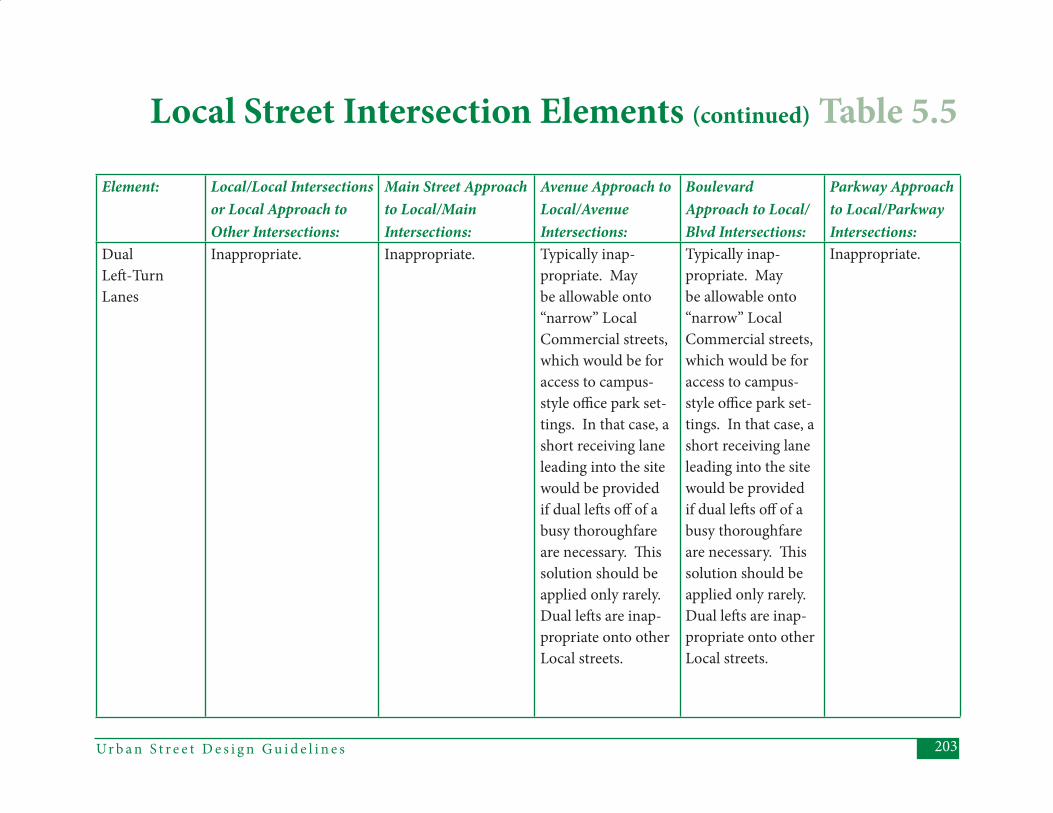
203Ur b a n S t r e e t D e s i g n G u i d e l i n e s
Element: Local/Local Intersections or Local Approach to Other Intersections:
Main Street Approach to Local/Main Intersections:
Avenue Approach to Local/AvenueIntersections:
Boulevard Approach to Local/Blvd Intersections:
Parkway Approach to Local/Parkway Intersections:
DualLeft -TurnLanes
Inappropriate. Inappropriate. Typically inap-propriate. May be allowable onto “narrow” Local Commercial streets, which would be for access to campus-style offi ce park set-tings. In that case, a short receiving lane leading into the site would be provided if dual left s off of a busy thoroughfare are necessary. Th is solution should be applied only rarely. Dual left s are inap-propriate onto other Local streets.
Typically inap-propriate. May be allowable onto “narrow” Local Commercial streets, which would be for access to campus-style offi ce park set-tings. In that case, a short receiving lane leading into the site would be provided if dual left s off of a busy thoroughfare are necessary. Th is solution should be applied only rarely. Dual left s are inap-propriate onto other Local streets.
Inappropriate.
Local Street Intersection Elements (continued) Table 5.5
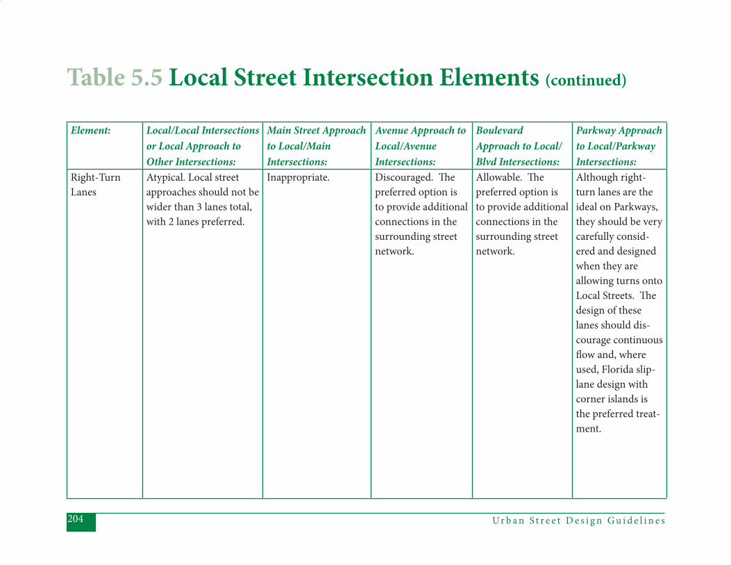
Ur b a n S t r e e t D e s i g n G u i d e l i n e s204
Element: Local/Local Intersections or Local Approach to Other Intersections:
Main Street Approach to Local/Main Intersections:
Avenue Approach to Local/AvenueIntersections:
Boulevard Approach to Local/Blvd Intersections:
Parkway Approach to Local/Parkway Intersections:
Right-TurnLanes
Atypical. Local street approaches should not be wider than 3 lanes total, with 2 lanes preferred.
Inappropriate. Discouraged. Th e preferred option is to provide additional connections in the surrounding street network.
Allowable. Th e preferred option is to provide additional connections in the surrounding street network.
Although right-turn lanes are the ideal on Parkways, they should be very carefully consid-ered and designed when they are allowing turns onto Local Streets. Th e design of these lanes should dis-courage continuous fl ow and, where used, Florida slip-lane design with corner islands is the preferred treat-ment.
Table 5.5 Local Street Intersection Elements (continued)
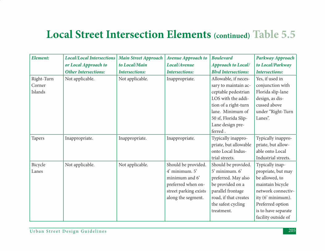
205Ur b a n S t r e e t D e s i g n G u i d e l i n e s
Element: Local/Local Intersections or Local Approach to Other Intersections:
Main Street Approach to Local/Main Intersections:
Avenue Approach to Local/AvenueIntersections:
Boulevard Approach to Local/Blvd Intersections:
Parkway Approach to Local/Parkway Intersections:
Right-TurnCornerIslands
Not applicable. Not applicable. Inappropriate. Allowable, if neces-sary to maintain ac-ceptable pedestrian LOS with the addi-tion of a right-turn lane. Minimum of 50 sf, Florida Slip-Lane design pre-ferred .
Yes, if used in conjunction with Florida slip-lane design, as dis-cussed above under “Right-Turn Lanes”.
Tapers Inappropriate. Inappropriate. Inappropriate. Typically inappro-priate, but allowable onto Local Indus-trial streets.
Typically inappro-priate, but allow-able onto Local Industrial streets.
BicycleLanes
Not applicable. Not applicable. Should be provided. 4’ minimum. 5’ minimum and 6’ preferred when on-street parking exists along the segment.
Should be provided. 5’ minimum. 6’ preferred. May also be provided on a parallel frontage road, if that creates the safest cycling treatment.
Typically inap-propriate, but may be allowed, to maintain bicycle network connectiv-ity (6’ minimum). Preferred option is to have separate facility outside of
Local Street Intersection Elements (continued) Table 5.5
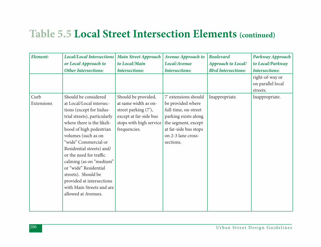
Ur b a n S t r e e t D e s i g n G u i d e l i n e s206
Element: Local/Local Intersections or Local Approach to Other Intersections:
Main Street Approach to Local/Main Intersections:
Avenue Approach to Local/AvenueIntersections:
Boulevard Approach to Local/Blvd Intersections:
Parkway Approach to Local/Parkway Intersections:right-of-way or on parallel local streets.
CurbExtensions
Should be considered at Local/Local intersec-tions (except for Indus-trial streets), particularly where there is the likeli-hood of high pedestrian volumes (such as on “wide” Commercial or Residential streets) and/or the need for traffi c calming (as on “medium” or “wide” Residential streets). Should be provided at intersections with Main Streets and are allowed at Avenues.
Should be provided, at same width as on-street parking (7’), except at far-side bus stops with high service frequencies.
7’ extensions should be provided where full-time, on-street parking exists along the segment, except at far-side bus stops on 2-3 lane cross-sections.
Inappropriate. Inappropriate.
Table 5.5 Local Street Intersection Elements (continued)
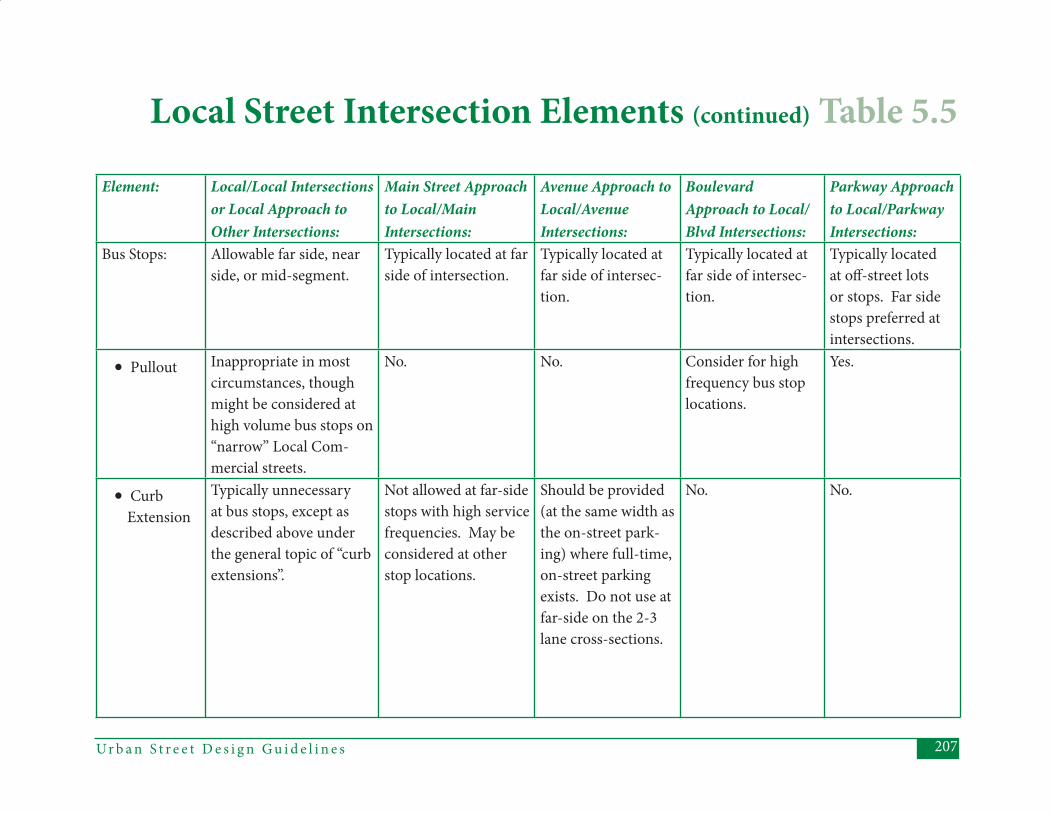
207Ur b a n S t r e e t D e s i g n G u i d e l i n e s
Element: Local/Local Intersections or Local Approach to Other Intersections:
Main Street Approach to Local/Main Intersections:
Avenue Approach to Local/AvenueIntersections:
Boulevard Approach to Local/Blvd Intersections:
Parkway Approach to Local/Parkway Intersections:
Bus Stops: Allowable far side, near side, or mid-segment.
Typically located at far side of intersection.
Typically located at far side of intersec-tion.
Typically located at far side of intersec-tion.
Typically located at off -street lots or stops. Far side stops preferred at intersections.
• Pullout Inappropriate in most circumstances, though might be considered at high volume bus stops on “narrow” Local Com-mercial streets.
No. No. Consider for high frequency bus stop locations.
Yes.
• Curb Extension
Typically unnecessary at bus stops, except as described above under the general topic of “curb extensions”.
Not allowed at far-side stops with high service frequencies. May be considered at other stop locations.
Should be provided (at the same width as the on-street park-ing) where full-time, on-street parking exists. Do not use at far-side on the 2-3 lane cross-sections.
No. No.
Local Street Intersection Elements (continued) Table 5.5
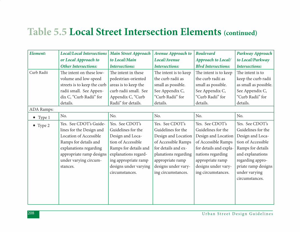
Ur b a n S t r e e t D e s i g n G u i d e l i n e s208
Element: Local/Local Intersections or Local Approach to Other Intersections:
Main Street Approach to Local/Main Intersections:
Avenue Approach to Local/AvenueIntersections:
Boulevard Approach to Local/Blvd Intersections:
Parkway Approach to Local/Parkway Intersections:
Curb Radii Th e intent on these low-volume and low-speed streets is to keep the curb radii small. See Appen-dix C, “Curb Radii” for details.
Th e intent in these pedestrian-oriented areas is to keep the curb radii small. See Appendix C, “Curb Radii” for details.
Th e intent is to keep the curb radii as small as possible. See Appendix C, “Curb Radii” for details.
Th e intent is to keep the curb radii as small as possible. See Appendix C, “Curb Radii” for details.
Th e intent is to keep the curb radii as small as possible. See Appendix C, “Curb Radii” for details.
ADA Ramps:
• Type 1 No. No. No. No. No.
• Type 2 Yes. See CDOT’s Guide-lines for the Design and Location of Accessible Ramps for details and explanations regarding appropriate ramp designs under varying circum-stances.
Yes. See CDOT’s Guidelines for the Design and Loca-tion of Accessible Ramps for details and explanations regard-ing appropriate ramp designs under varying circumstances.
Yes. See CDOT’s Guidelines for the Design and Location of Accessible Ramps for details and ex-planations regarding appropriate ramp designs under vary-ing circumstances.
Yes. See CDOT’s Guidelines for the Design and Location of Accessible Ramps for details and expla-nations regarding appropriate ramp designs under vary-ing circumstances.
Yes. See CDOT’s Guidelines for the Design and Loca-tion of Accessible Ramps for details and explanations regarding appro-priate ramp designs under varying circumstances.
Table 5.5 Local Street Intersection Elements (continued)
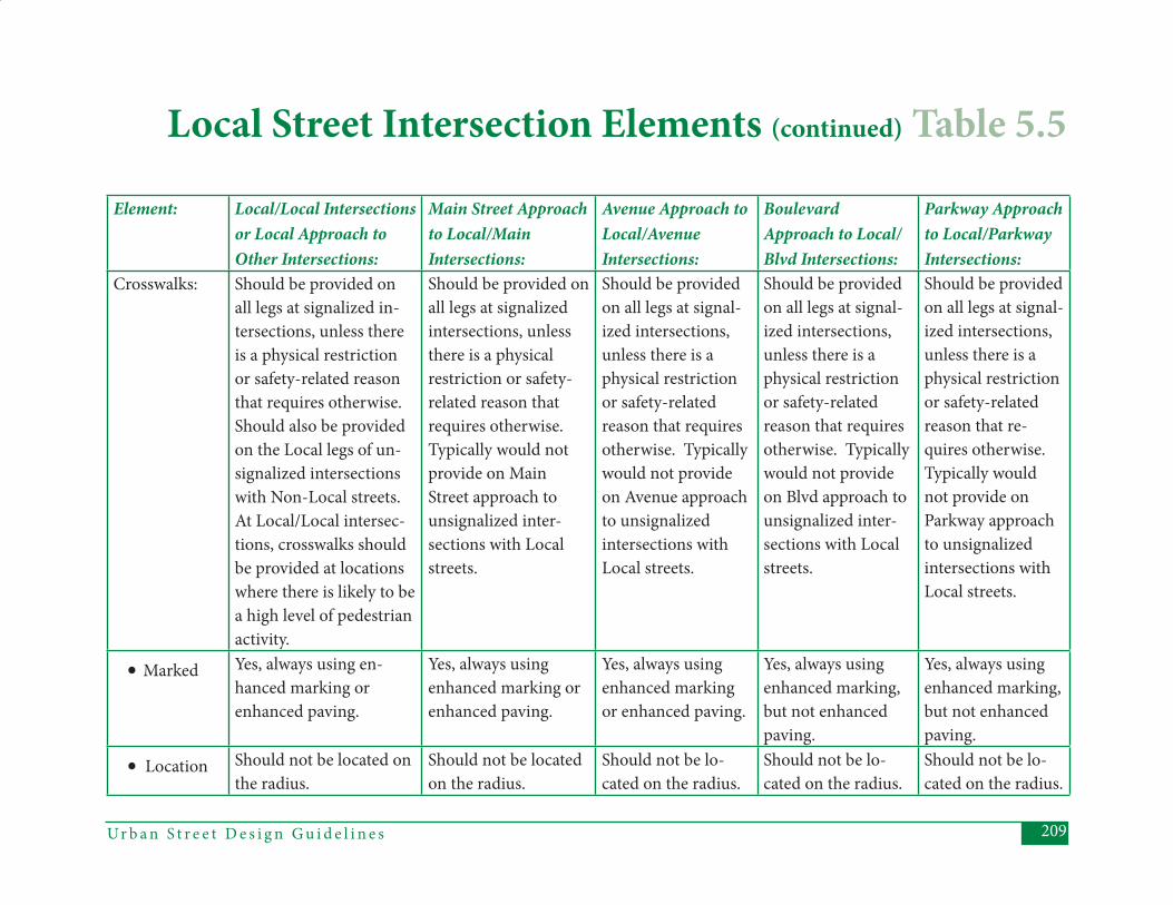
209Ur b a n S t r e e t D e s i g n G u i d e l i n e s
Element: Local/Local Intersections or Local Approach to Other Intersections:
Main Street Approach to Local/Main Intersections:
Avenue Approach to Local/AvenueIntersections:
Boulevard Approach to Local/Blvd Intersections:
Parkway Approach to Local/Parkway Intersections:
Crosswalks: Should be provided on all legs at signalized in-tersections, unless there is a physical restriction or safety-related reason that requires otherwise. Should also be provided on the Local legs of un-signalized intersections with Non-Local streets. At Local/Local intersec-tions, crosswalks should be provided at locations where there is likely to be a high level of pedestrian activity.
Should be provided on all legs at signalized intersections, unless there is a physical restriction or safety-related reason that requires otherwise. Typically would not provide on Main Street approach to unsignalized inter-sections with Local streets.
Should be provided on all legs at signal-ized intersections, unless there is a physical restriction or safety-related reason that requires otherwise. Typically would not provide on Avenue approach to unsignalized intersections with Local streets.
Should be provided on all legs at signal-ized intersections, unless there is a physical restriction or safety-related reason that requires otherwise. Typically would not provide on Blvd approach to unsignalized inter-sections with Local streets.
Should be provided on all legs at signal-ized intersections, unless there is a physical restriction or safety-related reason that re-quires otherwise. Typically would not provide on Parkway approach to unsignalized intersections with Local streets.
• Marked Yes, always using en-hanced marking or enhanced paving.
Yes, always using enhanced marking or enhanced paving.
Yes, always using enhanced marking or enhanced paving.
Yes, always using enhanced marking, but not enhanced paving.
Yes, always using enhanced marking, but not enhanced paving.
• Location Should not be located on the radius.
Should not be located on the radius.
Should not be lo-cated on the radius.
Should not be lo-cated on the radius.
Should not be lo-cated on the radius.
Local Street Intersection Elements (continued) Table 5.5
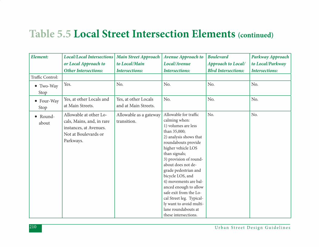
Ur b a n S t r e e t D e s i g n G u i d e l i n e s210
Element: Local/Local Intersections or Local Approach to Other Intersections:
Main Street Approach to Local/Main Intersections:
Avenue Approach to Local/AvenueIntersections:
Boulevard Approach to Local/Blvd Intersections:
Parkway Approach to Local/Parkway Intersections:
Traffi c Control:
• Two-Way Stop
Yes. No. No. No. No.
• Four-Way Stop
Yes, at other Locals and at Main Streets.
Yes, at other Locals and at Main Streets.
No. No. No.
• Round- about
Allowable at other Lo-cals, Mains, and, in rare instances, at Avenues. Not at Boulevards or Parkways.
Allowable as a gateway transition.
Allowable for traffi c calming when: 1) volumes are less than 35,000; 2) analysis shows that roundabouts provide higher vehicle LOS than signals; 3) provision of round-about does not de-grade pedestrian and bicycle LOS, and 4) movements are bal-anced enough to allow safe exit from the Lo-cal Street leg. Typical-ly want to avoid multi-lane roundabouts at these intersections.
No. No.
Table 5.5 Local Street Intersection Elements (continued)
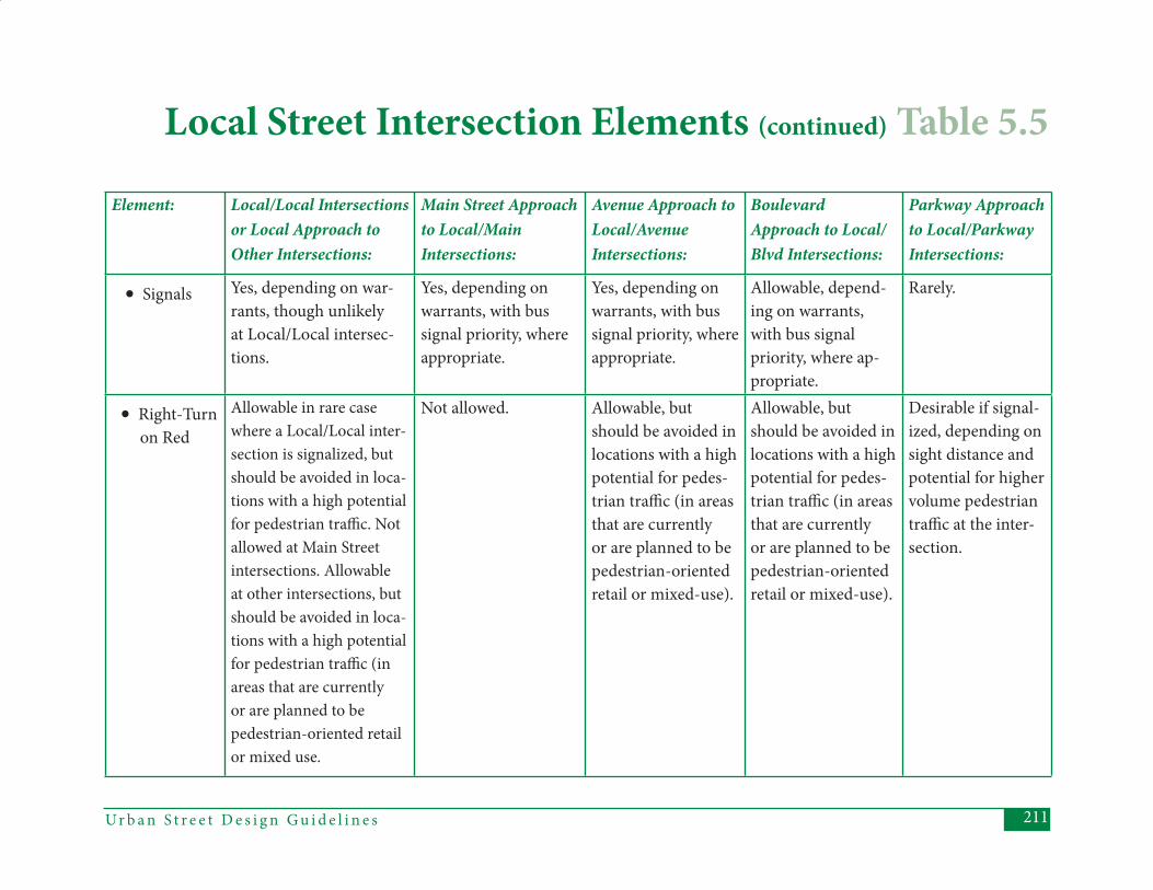
211Ur b a n S t r e e t D e s i g n G u i d e l i n e s
Element: Local/Local Intersections or Local Approach to Other Intersections:
Main Street Approach to Local/Main Intersections:
Avenue Approach to Local/AvenueIntersections:
Boulevard Approach to Local/Blvd Intersections:
Parkway Approach to Local/Parkway Intersections:
• Signals Yes, depending on war-rants, though unlikely at Local/Local intersec-tions.
Yes, depending on warrants, with bus signal priority, where appropriate.
Yes, depending on warrants, with bus signal priority, where appropriate.
Allowable, depend-ing on warrants, with bus signal priority, where ap-propriate.
Rarely.
• Right-Turn on Red
Allowable in rare case where a Local/Local inter-section is signalized, but should be avoided in loca-tions with a high potential for pedestrian traffi c. Not allowed at Main Street intersections. Allowable at other intersections, but should be avoided in loca-tions with a high potential for pedestrian traffi c (in areas that are currently or are planned to be pedestrian-oriented retail or mixed use.
Not allowed. Allowable, but should be avoided in locations with a high potential for pedes-trian traffi c (in areas that are currently or are planned to be pedestrian-oriented retail or mixed-use).
Allowable, but should be avoided in locations with a high potential for pedes-trian traffi c (in areas that are currently or are planned to be pedestrian-oriented retail or mixed-use).
Desirable if signal-ized, depending on sight distance and potential for higher volume pedestrian traffi c at the inter-section.
Local Street Intersection Elements (continued) Table 5.5
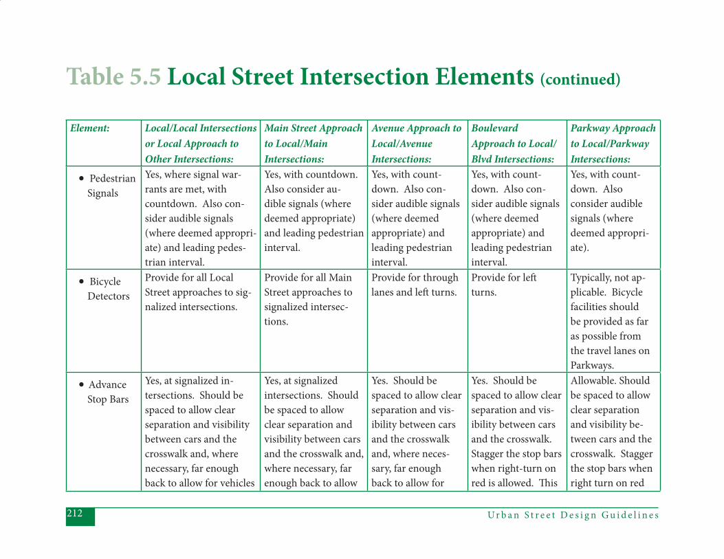
Ur b a n S t r e e t D e s i g n G u i d e l i n e s212
Element: Local/Local Intersections or Local Approach to Other Intersections:
Main Street Approach to Local/Main Intersections:
Avenue Approach to Local/AvenueIntersections:
Boulevard Approach to Local/Blvd Intersections:
Parkway Approach to Local/Parkway Intersections:
• Pedestrian Signals
Yes, where signal war-rants are met, with countdown. Also con-sider audible signals (where deemed appropri-ate) and leading pedes-trian interval.
Yes, with countdown. Also consider au-dible signals (where deemed appropriate) and leading pedestrian interval.
Yes, with count-down. Also con-sider audible signals (where deemed appropriate) and leading pedestrian interval.
Yes, with count-down. Also con-sider audible signals (where deemed appropriate) and leading pedestrian interval.
Yes, with count-down. Also consider audible signals (where deemed appropri-ate).
• Bicycle Detectors
Provide for all Local Street approaches to sig-nalized intersections.
Provide for all Main Street approaches to signalized intersec-tions.
Provide for through lanes and left turns.
Provide for left turns.
Typically, not ap-plicable. Bicycle facilities should be provided as far as possible from the travel lanes on Parkways.
• Advance Stop Bars
Yes, at signalized in-tersections. Should be spaced to allow clear separation and visibility between cars and the crosswalk and, where necessary, far enoughback to allow for vehicles
Yes, at signalized intersections. Should be spaced to allow clear separation and visibility between cars and the crosswalk and, where necessary, farenough back to allow
Yes. Should be spaced to allow clear separation and vis-ibility between cars and the crosswalk and, where neces-sary, far enough back to allow for
Yes. Should be spaced to allow clear separation and vis-ibility between cars and the crosswalk. Stagger the stop bars when right-turn onred is allowed. Th is
Allowable. Should be spaced to allow clear separation and visibility be-tween cars and the crosswalk. Stagger the stop bars whenright turn on red
Table 5.5 Local Street Intersection Elements (continued)
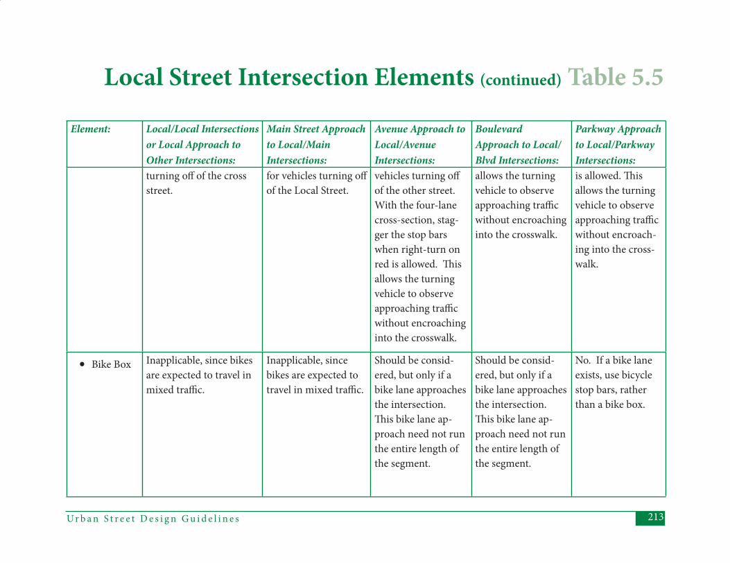
213Ur b a n S t r e e t D e s i g n G u i d e l i n e s
Element: Local/Local Intersections or Local Approach to Other Intersections:
Main Street Approach to Local/Main Intersections:
Avenue Approach to Local/AvenueIntersections:
Boulevard Approach to Local/Blvd Intersections:
Parkway Approach to Local/Parkway Intersections:
turning off of the cross street.
for vehicles turning off of the Local Street.
vehicles turning off of the other street. With the four-lane cross-section, stag-ger the stop bars when right-turn on red is allowed. Th is allows the turning vehicle to observe approaching traffi c without encroaching into the crosswalk.
allows the turning vehicle to observe approaching traffi c without encroaching into the crosswalk.
is allowed. Th is allows the turning vehicle to observe approaching traffi c without encroach-ing into the cross-walk.
• Bike Box Inapplicable, since bikes are expected to travel in mixed traffi c.
Inapplicable, since bikes are expected to travel in mixed traffi c.
Should be consid-ered, but only if a bike lane approaches the intersection. Th is bike lane ap-proach need not run the entire length of the segment.
Should be consid-ered, but only if a bike lane approaches the intersection. Th is bike lane ap-proach need not run the entire length of the segment.
No. If a bike lane exists, use bicycle stop bars, rather than a bike box.
Local Street Intersection Elements (continued) Table 5.5
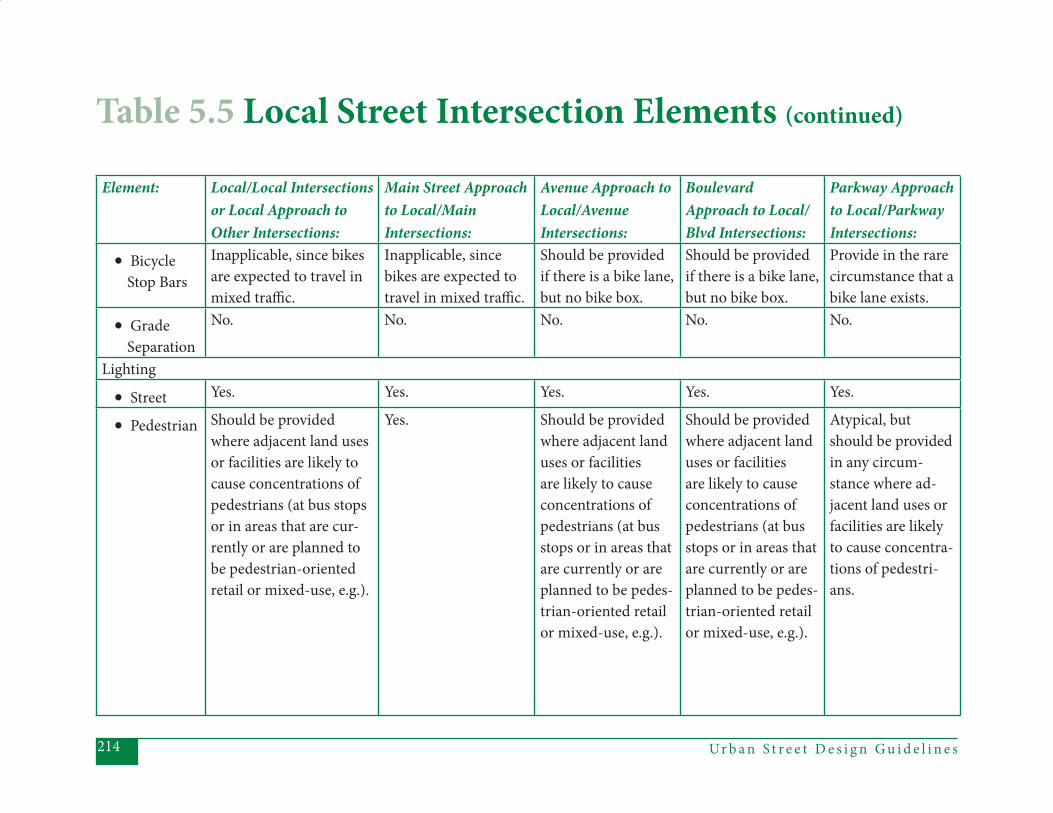
Ur b a n S t r e e t D e s i g n G u i d e l i n e s214
Element: Local/Local Intersections or Local Approach to Other Intersections:
Main Street Approach to Local/Main Intersections:
Avenue Approach to Local/AvenueIntersections:
Boulevard Approach to Local/Blvd Intersections:
Parkway Approach to Local/Parkway Intersections:
• Bicycle Stop Bars
Inapplicable, since bikes are expected to travel in mixed traffi c.
Inapplicable, since bikes are expected to travel in mixed traffi c.
Should be provided if there is a bike lane, but no bike box.
Should be provided if there is a bike lane, but no bike box.
Provide in the rare circumstance that a bike lane exists.
• Grade Separation
No. No. No. No. No.
Lighting
• Street Yes. Yes. Yes. Yes. Yes.
• Pedestrian Should be provided where adjacent land uses or facilities are likely to cause concentrations of pedestrians (at bus stops or in areas that are cur-rently or are planned to be pedestrian-oriented retail or mixed-use, e.g.).
Yes. Should be provided where adjacent land uses or facilities are likely to cause concentrations of pedestrians (at bus stops or in areas that are currently or are planned to be pedes-trian-oriented retail or mixed-use, e.g.).
Should be provided where adjacent land uses or facilities are likely to cause concentrations of pedestrians (at bus stops or in areas that are currently or are planned to be pedes-trian-oriented retail or mixed-use, e.g.).
Atypical, but should be provided in any circum-stance where ad-jacent land uses or facilities are likely to cause concentra-tions of pedestri-ans.
Table 5.5 Local Street Intersection Elements (continued)
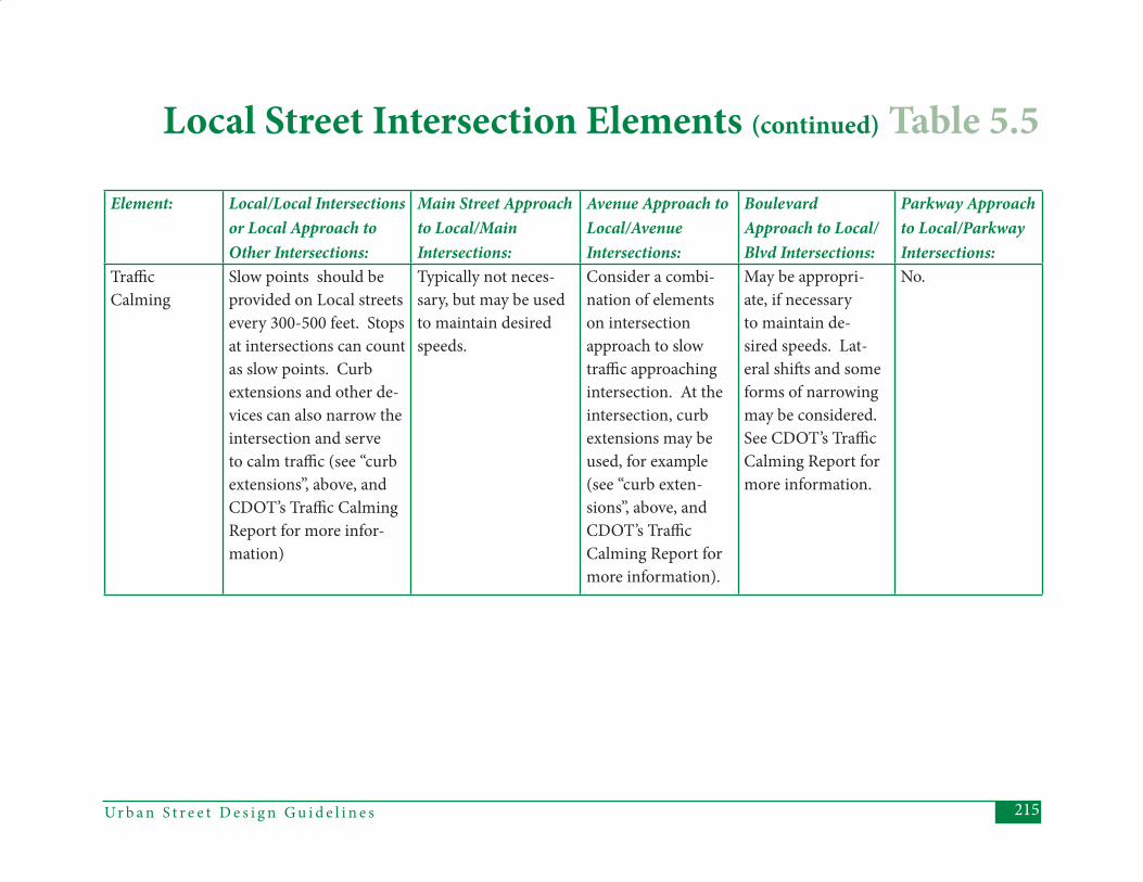
215Ur b a n S t r e e t D e s i g n G u i d e l i n e s
Element: Local/Local Intersections or Local Approach to Other Intersections:
Main Street Approach to Local/Main Intersections:
Avenue Approach to Local/AvenueIntersections:
Boulevard Approach to Local/Blvd Intersections:
Parkway Approach to Local/Parkway Intersections:
Traffi cCalming
Slow points should be provided on Local streets every 300-500 feet. Stops at intersections can count as slow points. Curb extensions and other de-vices can also narrow the intersection and serve to calm traffi c (see “curb extensions”, above, and CDOT’s Traffi c Calming Report for more infor-mation)
Typically not neces-sary, but may be used to maintain desired speeds.
Consider a combi-nation of elements on intersection approach to slow traffi c approaching intersection. At the intersection, curb extensions may be used, for example (see “curb exten-sions”, above, and CDOT’s Traffi c Calming Report for more information).
May be appropri-ate, if necessary to maintain de-sired speeds. Lat-eral shift s and some forms of narrowing may be considered. See CDOT’s Traffi c Calming Report for more information.
No.
Local Street Intersection Elements (continued) Table 5.5

Ur b a n S t r e e t D e s i g n G u i d e l i n e s216
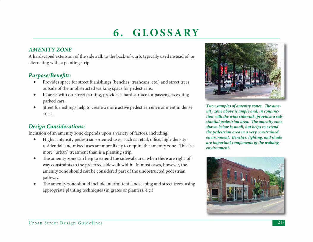
217Ur b a n S t r e e t D e s i g n G u i d e l i n e s
6 . G L O S S A RYAMENITY ZONEA hardscaped extension of the sidewalk to the back-of-curb, typically used instead of, or alternating with, a planting strip.
Purpose/Benefi ts:• Provides space for street furnishings (benches, trashcans, etc.) and street trees
outside of the unobstructed walking space for pedestrians.• In areas with on-street parking, provides a hard surface for passengers exiting
parked cars.• Street furnishings help to create a more active pedestrian environment in dense
areas.
Design Considerations:Inclusion of an amenity zone depends upon a variety of factors, including:
• Higher intensity pedestrian-oriented uses, such as retail, offi ce, high-density residential, and mixed uses are more likely to require the amenity zone. Th is is a more “urban” treatment than is a planting strip.
• Th e amenity zone can help to extend the sidewalk area when there are right-of-way constraints to the preferred sidewalk width. In most cases, however, the amenity zone should not be considered part of the unobstructed pedestrian pathway.
• Th e amenity zone should include intermittent landscaping and street trees, using appropriate planting techniques (in grates or planters, e.g.).
Two examples of amenity zones. Th e ame-nity zone above is ample and, in conjunc-tion with the wide sidewalk, provides a sub-stantial pedestrian area. Th e amenity zone shown below is small, but helps to extend the pedestrian area in a very constrained environment. Benches, lighting, and shade are important components of the walking environment.
Ur b a n S t r e e t D e s i g n G u i d e l i n e s218
BICYCLE DETECTORA device at a signalized intersection used to detect bicycles for traffi c actuated signals.
Purpose/Benefi ts:• Activates the traffi c signal in the absence of motor vehicle traffi c, thereby keeping
the cyclist from having to wait for another vehicle to “trip” the signal or, aft er a prolonged wait, to run the signal.
Design Considerations:• Detectors should be located in the bicyclists’ expected path, whether the inter-
section includes bike lanes, a bike box, or a wide outside lane. • Bicycle detectors are most important on the less traveled leg of a signalized
intersection, because the wait for another vehicle to “trip” the light will be longer. However, a strong case can be made for using detectors on all legs, as the time of day can make a diff erence even on the more traveled legs.
• Markings on the roadway surface can be used to indicate the optimum location for bicycle detection.
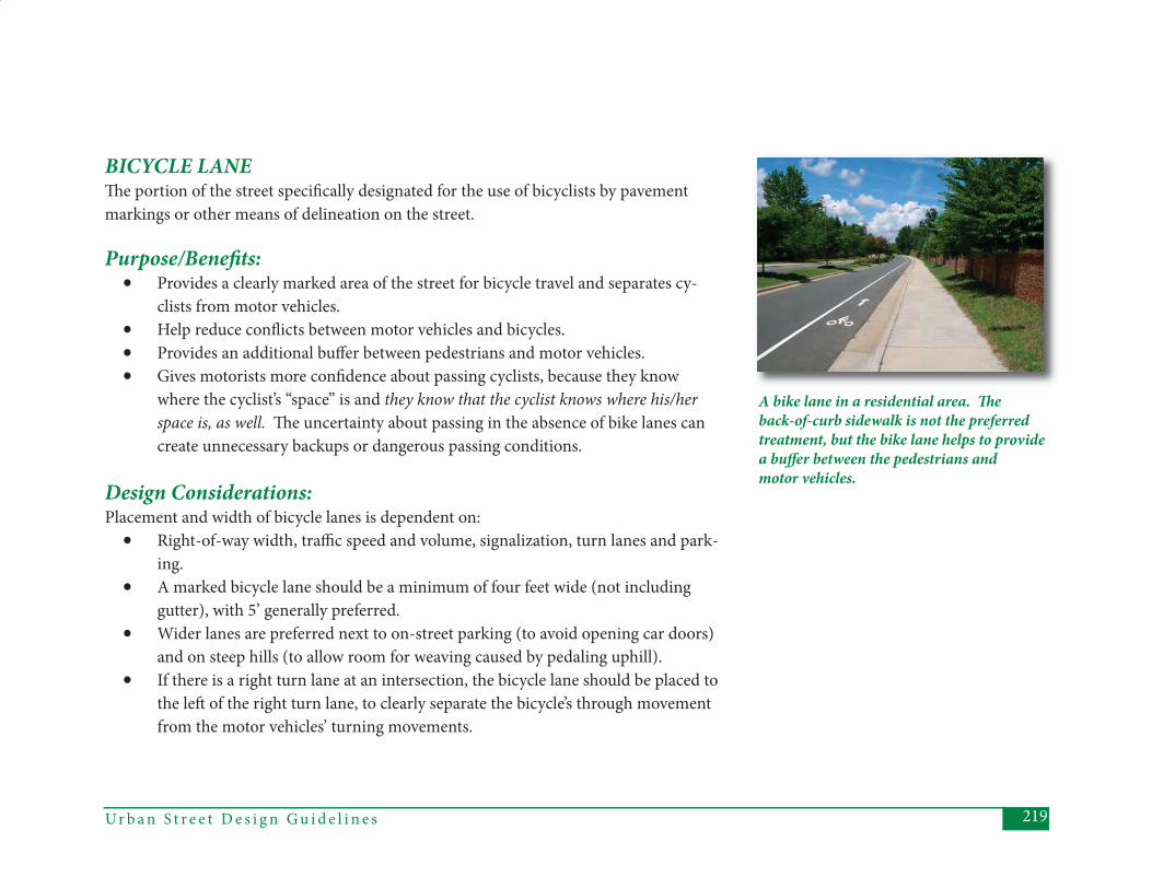
219Ur b a n S t r e e t D e s i g n G u i d e l i n e s
A bike lane in a residential area. Th e back-of-curb sidewalk is not the preferred treatment, but the bike lane helps to provide a buff er between the pedestrians and motor vehicles.
BICYCLE LANETh e portion of the street specifi cally designated for the use of bicyclists by pavement markings or other means of delineation on the street.
Purpose/Benefi ts:• Provides a clearly marked area of the street for bicycle travel and separates cy-
clists from motor vehicles.• Help reduce confl icts between motor vehicles and bicycles.• Provides an additional buff er between pedestrians and motor vehicles.• Gives motorists more confi dence about passing cyclists, because they know
where the cyclist’s “space” is and they know that the cyclist knows where his/her space is, as well. Th e uncertainty about passing in the absence of bike lanes can create unnecessary backups or dangerous passing conditions.
Design Considerations:Placement and width of bicycle lanes is dependent on:
• Right-of-way width, traffi c speed and volume, signalization, turn lanes and park-ing.
• A marked bicycle lane should be a minimum of four feet wide (not including gutter), with 5’ generally preferred.
• Wider lanes are preferred next to on-street parking (to avoid opening car doors) and on steep hills (to allow room for weaving caused by pedaling uphill).
• If there is a right turn lane at an intersection, the bicycle lane should be placed to the left of the right turn lane, to clearly separate the bicycle’s through movement from the motor vehicles’ turning movements.
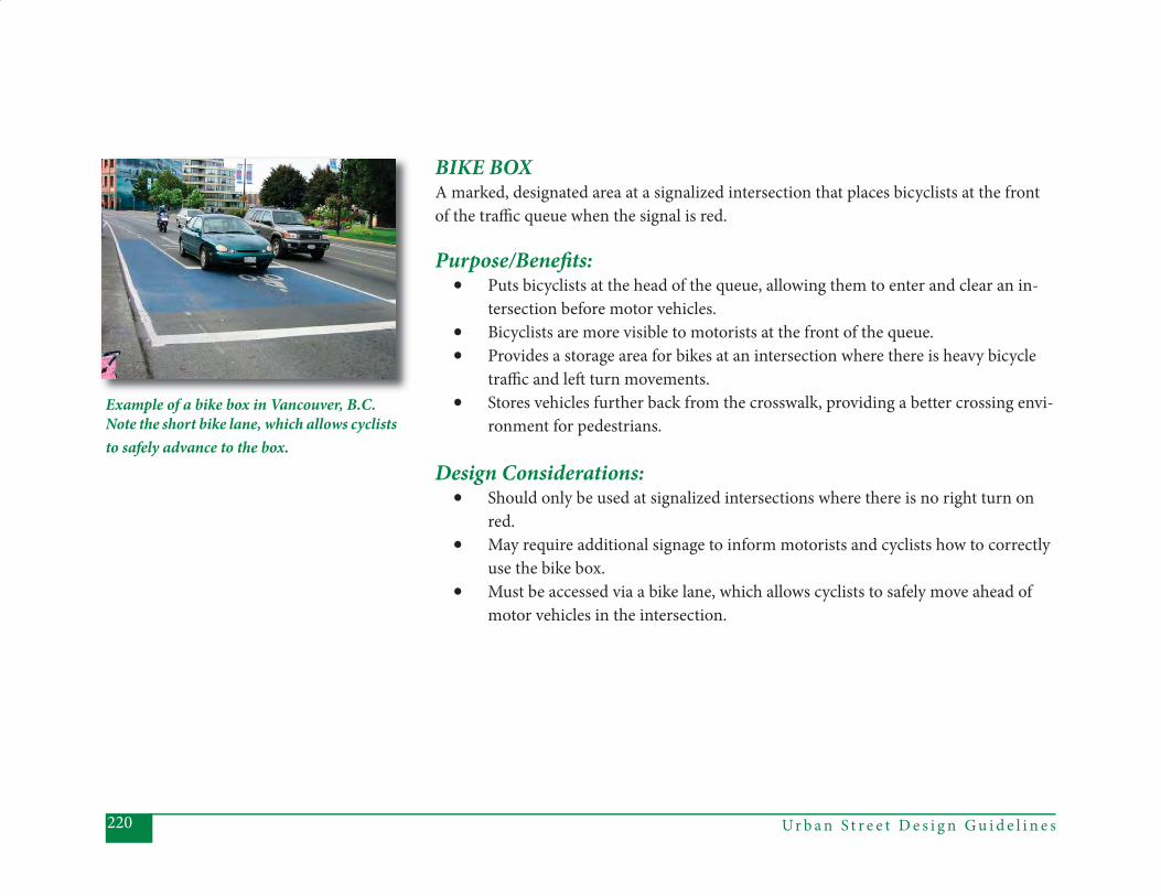
Ur b a n S t r e e t D e s i g n G u i d e l i n e s220
BIKE BOXA marked, designated area at a signalized intersection that places bicyclists at the front of the traffi c queue when the signal is red.
Purpose/Benefi ts:• Puts bicyclists at the head of the queue, allowing them to enter and clear an in-
tersection before motor vehicles.• Bicyclists are more visible to motorists at the front of the queue.• Provides a storage area for bikes at an intersection where there is heavy bicycle
traffi c and left turn movements.• Stores vehicles further back from the crosswalk, providing a better crossing envi-
ronment for pedestrians.
Design Considerations:• Should only be used at signalized intersections where there is no right turn on
red.• May require additional signage to inform motorists and cyclists how to correctly
use the bike box.• Must be accessed via a bike lane, which allows cyclists to safely move ahead of
motor vehicles in the intersection.
Example of a bike box in Vancouver, B.C.Note the short bike lane, which allows cyclists to safely advance to the box.
221Ur b a n S t r e e t D e s i g n G u i d e l i n e s
BLOCK LENGTHTh e longest dimension of a block, from intersection to intersection. Charlotte’s Street Design Guidelines recommend relatively short block lengths for most street types.
Purpose/Benefi ts:• Block lengths help determine the overall “density” of the street network, with
shorter blocks generally creating a denser network.• Shorter blocks (and a denser network) can help disperse traffi c through the
network, rather than focusing it on a few routes. Th e fewer route choices, the greater the likelihood that the routes will become congested.
• A denser network provides more route choices for all travelers by all modes. • Shorter block lengths and a denser network can allow more direct (and there-
fore, shorter) routes, a particularly important factor for pedestrians and cyclists.• Shorter blocks (and a denser network) allow for more fl exibility as a city grows.
Design Considerations:• Block length will vary according to street type and surrounding land uses.
Charlotte’s Urban Street Design Guidelines recommend that most street types have blocks no longer than 650’.
• Pedestrian, vehicular, and bicycle network connections should be considered when laying out the block structure.
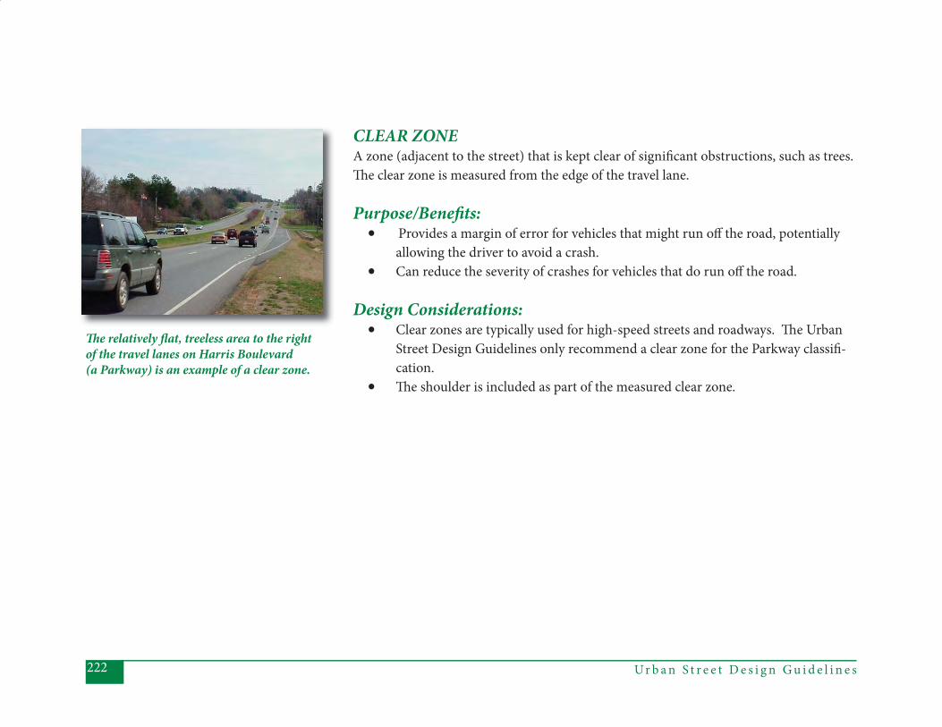
Ur b a n S t r e e t D e s i g n G u i d e l i n e s222
CLEAR ZONEA zone (adjacent to the street) that is kept clear of signifi cant obstructions, such as trees. Th e clear zone is measured from the edge of the travel lane.
Purpose/Benefi ts: • Provides a margin of error for vehicles that might run off the road, potentially
allowing the driver to avoid a crash.• Can reduce the severity of crashes for vehicles that do run off the road.
Design Considerations:• Clear zones are typically used for high-speed streets and roadways. Th e Urban
Street Design Guidelines only recommend a clear zone for the Parkway classifi -cation.
• Th e shoulder is included as part of the measured clear zone.
Th e relatively fl at, treeless area to the right of the travel lanes on Harris Boulevard (a Parkway) is an example of a clear zone.
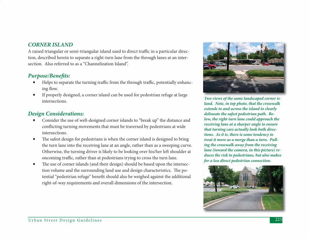
223Ur b a n S t r e e t D e s i g n G u i d e l i n e s
CORNER ISLANDA raised triangular or semi-triangular island used to direct traffi c in a particular direc-tion, described herein to separate a right-turn lane from the through lanes at an inter-section. Also referred to as a “Channelization Island”.
Purpose/Benefi ts: • Helps to separate the turning traffi c from the through traffi c, potentially enhanc-
ing fl ow.• If properly designed, a corner island can be used for pedestrian refuge at large
intersections.
Design Considerations:• Consider the use of well-designed corner islands to “break up” the distance and
confl icting turning movements that must be traversed by pedestrians at wide intersections.
• Th e safest design for pedestrians is when the corner island is designed to bring the turn lane into the receiving lane at an angle, rather than as a sweeping curve. Otherwise, the turning driver is likely to be looking over his/her left shoulder at oncoming traffi c, rather than at pedestrians trying to cross the turn lane.
• Th e use of corner islands (and their design) should be based upon the intersec-tion volume and the surrounding land use and design characteristics. Th e po-tential “pedestrian refuge” benefi t should also be weighed against the additional right-of-way requirements and overall dimensions of the intersection.
Two views of the same landscaped corner is-land. Note, in top photo, that the crosswalk extends to and across the island to clearly delineate the safest pedestrian path. Be-low, the right-turn lane could approach the receiving lane at a sharper angle to ensure that turning cars actually look both direc-tions. As it is, there is some tendency to treat it more as a merge than a turn. Pull-ing the crosswalk away from the receiving lane (toward the camera, in this picture) re-duces the risk to pedestrians, but also makes for a less direct pedestrian connection.
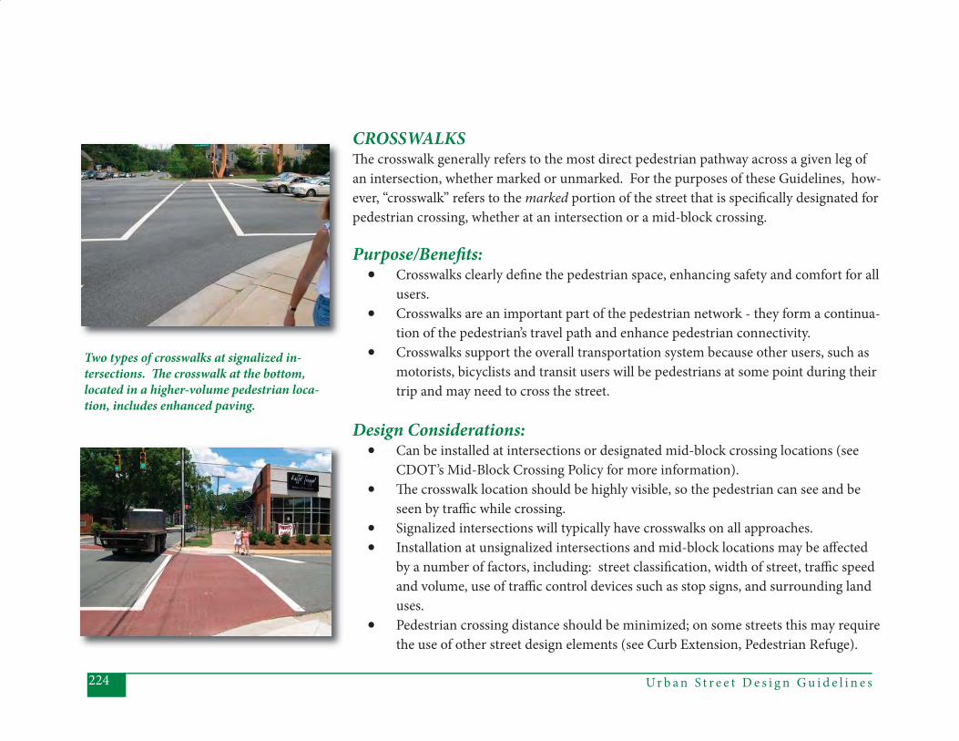
Ur b a n S t r e e t D e s i g n G u i d e l i n e s224
CROSSWALKSTh e crosswalk generally refers to the most direct pedestrian pathway across a given leg of an intersection, whether marked or unmarked. For the purposes of these Guidelines, how-ever, “crosswalk” refers to the marked portion of the street that is specifi cally designated for pedestrian crossing, whether at an intersection or a mid-block crossing.
Purpose/Benefi ts: • Crosswalks clearly defi ne the pedestrian space, enhancing safety and comfort for all
users. • Crosswalks are an important part of the pedestrian network - they form a continua-
tion of the pedestrian’s travel path and enhance pedestrian connectivity. • Crosswalks support the overall transportation system because other users, such as
motorists, bicyclists and transit users will be pedestrians at some point during their trip and may need to cross the street.
Design Considerations:• Can be installed at intersections or designated mid-block crossing locations (see
CDOT’s Mid-Block Crossing Policy for more information).• Th e crosswalk location should be highly visible, so the pedestrian can see and be
seen by traffi c while crossing. • Signalized intersections will typically have crosswalks on all approaches. • Installation at unsignalized intersections and mid-block locations may be aff ected
by a number of factors, including: street classifi cation, width of street, traffi c speed and volume, use of traffi c control devices such as stop signs, and surrounding land uses.
• Pedestrian crossing distance should be minimized; on some streets this may require the use of other street design elements (see Curb Extension, Pedestrian Refuge).
Two types of crosswalks at signalized in-tersections. Th e crosswalk at the bottom, located in a higher-volume pedestrian loca-tion, includes enhanced paving.
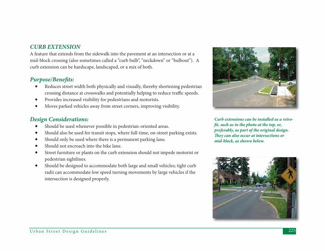
225Ur b a n S t r e e t D e s i g n G u i d e l i n e s
CURB EXTENSIONA feature that extends from the sidewalk into the pavement at an intersection or at a mid-block crossing (also sometimes called a “curb bulb”, “neckdown” or “bulbout”). A curb extension can be hardscape, landscaped, or a mix of both.
Purpose/Benefi ts: • Reduces street width both physically and visually, thereby shortening pedestrian
crossing distance at crosswalks and potentially helping to reduce traffi c speeds.• Provides increased visibility for pedestrians and motorists.• Moves parked vehicles away from street corners, improving visibility.
Design Considerations:• Should be used whenever possible in pedestrian-oriented areas.• Should also be used for transit stops, where full-time, on-street parking exists.• Should only be used where there is a permanent parking lane.• Should not encroach into the bike lane.• Street furniture or plants on the curb extension should not impede motorist or
pedestrian sightlines.• Should be designed to accommodate both large and small vehicles; tight curb
radii can accommodate low speed turning movements by large vehicles if the intersection is designed properly.
Curb extensions can be installed as a retro-fi t, such as in the photo at the top, or, preferably, as part of the original design. Th ey can also occur at intersections or mid-block, as shown below.
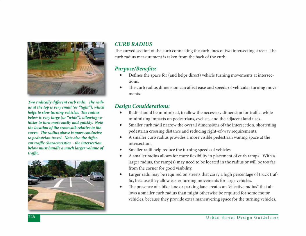
Ur b a n S t r e e t D e s i g n G u i d e l i n e s226
Two radically diff erent curb radii. Th e radi-us at the top is very small (or “tight”), which helps to slow turning vehicles. Th e radius below is very large (or “wide”), allowing ve-hicles to turn more easily and quickly. Note the location of the crosswalk relative to the curve. Th e radius above is more conducive to pedestrian travel. Note also the diff er-ent traffi c characteristics - the intersection below must handle a much larger volume of traffi c.
CURB RADIUSTh e curved section of the curb connecting the curb lines of two intersecting streets. Th e curb radius measurement is taken from the back of the curb.
Purpose/Benefi ts:• Defi nes the space for (and helps direct) vehicle turning movements at intersec-
tions.• Th e curb radius dimension can aff ect ease and speeds of vehicular turning move-
ments.
Design Considerations:• Radii should be minimized, to allow the necessary dimension for traffi c, while
minimizing impacts on pedestrians, cyclists, and the adjacent land uses. • Smaller curb radii narrow the overall dimensions of the intersection, shortening
pedestrian crossing distance and reducing right-of-way requirements. • A smaller curb radius provides a more visible pedestrian waiting space at the
intersection.• Smaller radii help reduce the turning speeds of vehicles.• A smaller radius allows for more fl exibility in placement of curb ramps. With a
larger radius, the ramp(s) may need to be located in the radius or will be too far from the corner for good visibility.
• Larger radii may be required on streets that carry a high percentage of truck traf-fi c, because they allow easier turning movements for large vehicles.
• Th e presence of a bike lane or parking lane creates an “eff ective radius” that al-lows a smaller curb radius than might otherwise be required for some motor vehicles, because they provide extra maneuvering space for the turning vehicles.
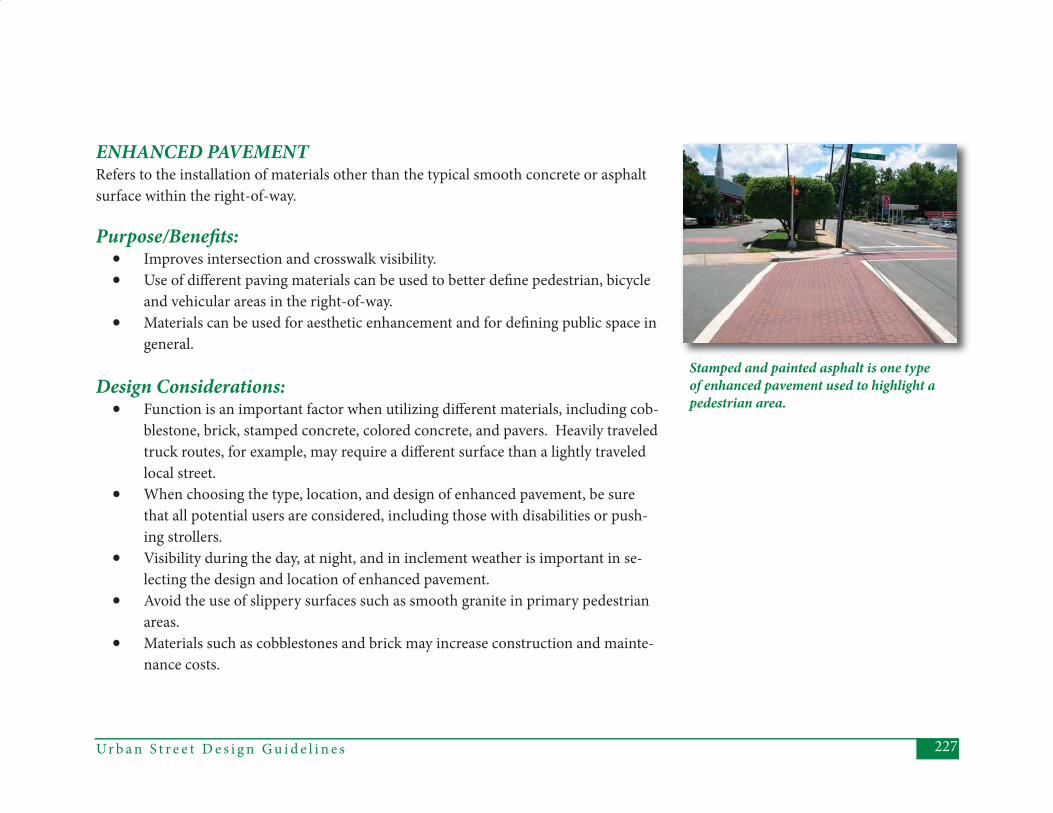
227Ur b a n S t r e e t D e s i g n G u i d e l i n e s
ENHANCED PAVEMENTRefers to the installation of materials other than the typical smooth concrete or asphalt surface within the right-of-way.
Purpose/Benefi ts:• Improves intersection and crosswalk visibility.• Use of diff erent paving materials can be used to better defi ne pedestrian, bicycle
and vehicular areas in the right-of-way.• Materials can be used for aesthetic enhancement and for defi ning public space in
general.
Design Considerations:• Function is an important factor when utilizing diff erent materials, including cob-
blestone, brick, stamped concrete, colored concrete, and pavers. Heavily traveled truck routes, for example, may require a diff erent surface than a lightly traveled local street.
• When choosing the type, location, and design of enhanced pavement, be sure that all potential users are considered, including those with disabilities or push-ing strollers.
• Visibility during the day, at night, and in inclement weather is important in se-lecting the design and location of enhanced pavement.
• Avoid the use of slippery surfaces such as smooth granite in primary pedestrian areas.
• Materials such as cobblestones and brick may increase construction and mainte-nance costs.
Stamped and painted asphalt is one type of enhanced pavement used to highlight a pedestrian area.
Ur b a n S t r e e t D e s i g n G u i d e l i n e s228
HIGH-INTENSITY ACTIVATED CROSSWALK (continued) A traffi c control beacon for pedestrians used to warn and control vehicular traffi c at mid-block locations. Also referred to as a “pedestrian beacon.” Th e design is unique because the device is dark until activated by a pedestrian. A yellow beacon fl ashes, turns to solid yellow, and then to a red indication. Aft er a period of time, the red indication “wig-wags,” to allow drivers to proceed if the pedestrian has cleared the crossing.
Note: Th e HAWK is currently approved for use on city-maintained streets as an experi-mental application. Th e new edition of the Manual on Uniform Traffi c Control Devices (MUTCD) will include provisions for a pedestrian beacon.
Purpose/Benefi ts:• Assists pedestrians in crossing a street or highway at a marked crosswalk.• Assigns right-of-way to the pedestrians, with the use of red indications for ve-
hicles and a walk indication for pedestrians.• Useful in locations where pedestrians have a diffi cult time fi nding gaps to cross
multi-lane roads.• Th is type of beacon has been found to have higher compliance rates in some ap-
plications than other types of pedestrian signals.
Design Considerations:• Typically pedestrian beacons are used on higher volume, higher speed streets.• Signs and pavement marking must be used in conjunction with the pedestrian
beacon.• Installation will typically be mid-block, away from an intersection, to avoid con-
fusion with side street traffi c.• Countdown pedestrian signals and APS devices should be used when possible.
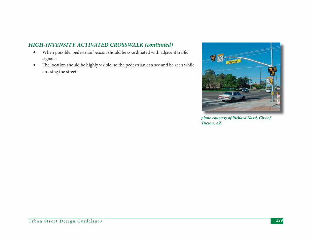
229Ur b a n S t r e e t D e s i g n G u i d e l i n e s
photo courtesy of Richard Nassi, City of Tucson, AZ
• When possible, pedestrian beacon should be coordinated with adjacent traffi c signals.
• Th e location should be highly visible, so the pedestrian can see and be seen while crossing the street.
HIGH-INTENSITY ACTIVATED CROSSWALK (continued)
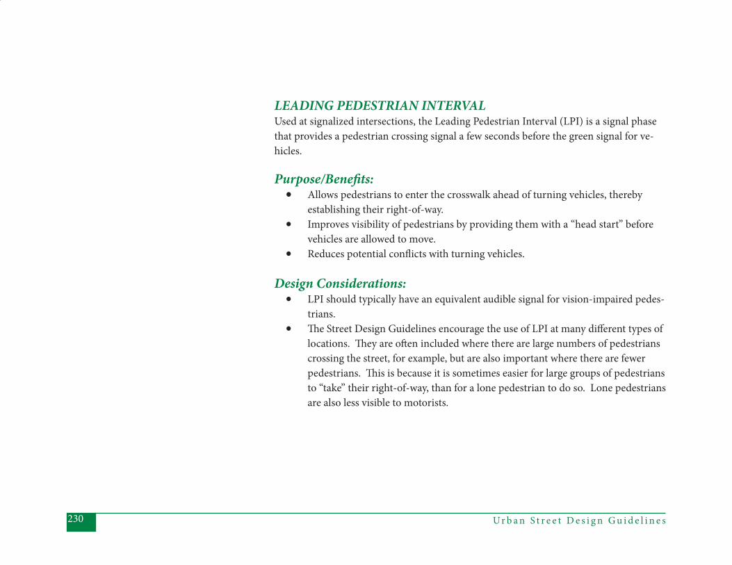
Ur b a n S t r e e t D e s i g n G u i d e l i n e s230
LEADING PEDESTRIAN INTERVALUsed at signalized intersections, the Leading Pedestrian Interval (LPI) is a signal phase that provides a pedestrian crossing signal a few seconds before the green signal for ve-hicles.
Purpose/Benefi ts:• Allows pedestrians to enter the crosswalk ahead of turning vehicles, thereby
establishing their right-of-way.• Improves visibility of pedestrians by providing them with a “head start” before
vehicles are allowed to move.• Reduces potential confl icts with turning vehicles.
Design Considerations:• LPI should typically have an equivalent audible signal for vision-impaired pedes-
trians.• Th e Street Design Guidelines encourage the use of LPI at many diff erent types of
locations. Th ey are oft en included where there are large numbers of pedestrians crossing the street, for example, but are also important where there are fewer pedestrians. Th is is because it is sometimes easier for large groups of pedestrians to “take” their right-of-way, than for a lone pedestrian to do so. Lone pedestrians are also less visible to motorists.
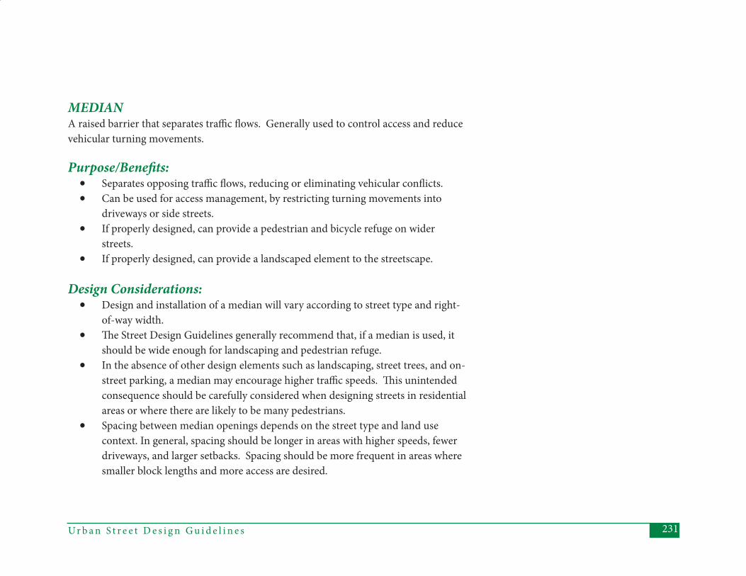
231Ur b a n S t r e e t D e s i g n G u i d e l i n e s
MEDIANA raised barrier that separates traffi c fl ows. Generally used to control access and reduce vehicular turning movements.
Purpose/Benefi ts:• Separates opposing traffi c fl ows, reducing or eliminating vehicular confl icts.• Can be used for access management, by restricting turning movements into
driveways or side streets.• If properly designed, can provide a pedestrian and bicycle refuge on wider
streets.• If properly designed, can provide a landscaped element to the streetscape.
Design Considerations:• Design and installation of a median will vary according to street type and right-
of-way width. • Th e Street Design Guidelines generally recommend that, if a median is used, it
should be wide enough for landscaping and pedestrian refuge. • In the absence of other design elements such as landscaping, street trees, and on-
street parking, a median may encourage higher traffi c speeds. Th is unintended consequence should be carefully considered when designing streets in residential areas or where there are likely to be many pedestrians.
• Spacing between median openings depends on the street type and land use context. In general, spacing should be longer in areas with higher speeds, fewer driveways, and larger setbacks. Spacing should be more frequent in areas where smaller block lengths and more access are desired.
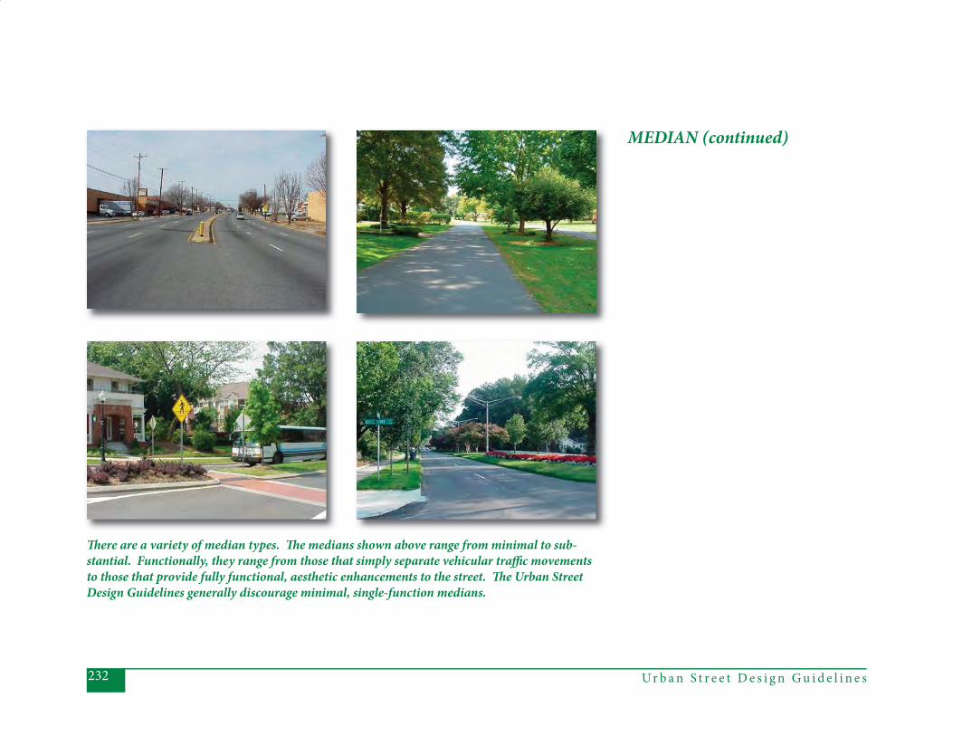
Ur b a n S t r e e t D e s i g n G u i d e l i n e s232
Th ere are a variety of median types. Th e medians shown above range from minimal to sub-stantial. Functionally, they range from those that simply separate vehicular traffi c movements to those that provide fully functional, aesthetic enhancements to the street. Th e Urban Street Design Guidelines generally discourage minimal, single-function medians.
MEDIAN (continued)

233Ur b a n S t r e e t D e s i g n G u i d e l i n e s
ON-STREET PARKINGGenerally refers to space for parking cars within the street right-of-way (between the curbs), as opposed to off -street parking areas accessed via driveways.
P u r p o s e / B e n e f i t s :• Provides improved access to nearby land uses, especially in higher density neigh-
borhoods and commercial areas.• Reduces the need for large, off -street parking areas. • Provides a buff er between moving vehicles and pedestrians on the sidewalk. • On-street parking can narrow the perceived right-of-way width and help reduce
traffi c speed.
Design Considerations:• On-street parking will be allowed on many local streets, but not necessarily
designated with marked spaces. Most of the information here refers to marked on-street parking.
• High-speed street types are not suitable for on-street parking.• Cars parked in on-street parking spaces should not impede visibility for pedes-
trians, bicyclists and other vehicles. Th is means that on-street parking spaces should be located carefully relative to intersections and crosswalks.
• Th e provision of on-street parking depends on street width as well as traffi c speed. Angled or reverse angle parking requires more roadway space than paral-lel parking, but can accommodate more vehicles per block.
• On-street parking can be allowed at some times of the day and disallowed at peak traffi c times. Th is can allow more effi cient use of lane capacity when it is needed.
• Where dedicated, full time on-street parking is provided, curb extensions can make pedestrians more visible at crossing points.
On-street parking on a commercial street.
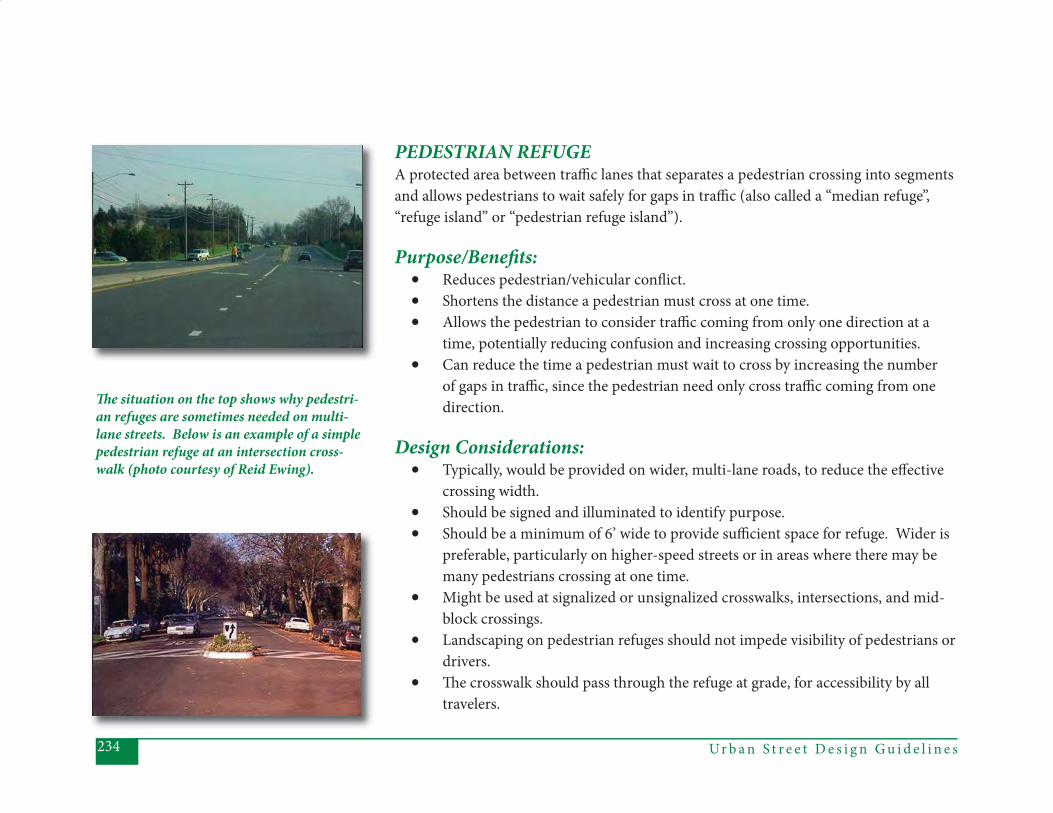
Ur b a n S t r e e t D e s i g n G u i d e l i n e s234
PEDESTRIAN REFUGEA protected area between traffi c lanes that separates a pedestrian crossing into segments and allows pedestrians to wait safely for gaps in traffi c (also called a “median refuge”, “refuge island” or “pedestrian refuge island”).
Purpose/Benefi ts:• Reduces pedestrian/vehicular confl ict.• Shortens the distance a pedestrian must cross at one time. • Allows the pedestrian to consider traffi c coming from only one direction at a
time, potentially reducing confusion and increasing crossing opportunities. • Can reduce the time a pedestrian must wait to cross by increasing the number
of gaps in traffi c, since the pedestrian need only cross traffi c coming from one direction.
Design Considerations: • Typically, would be provided on wider, multi-lane roads, to reduce the eff ective
crossing width. • Should be signed and illuminated to identify purpose.• Should be a minimum of 6’ wide to provide suffi cient space for refuge. Wider is
preferable, particularly on higher-speed streets or in areas where there may be many pedestrians crossing at one time.
• Might be used at signalized or unsignalized crosswalks, intersections, and mid-block crossings.
• Landscaping on pedestrian refuges should not impede visibility of pedestrians or drivers.
• Th e crosswalk should pass through the refuge at grade, for accessibility by all travelers.
Th e situation on the top shows why pedestri-an refuges are sometimes needed on multi-lane streets. Below is an example of a simple pedestrian refuge at an intersection cross-walk (photo courtesy of Reid Ewing).

235Ur b a n S t r e e t D e s i g n G u i d e l i n e s
Th is image is an example of a pedestrian refuge without a crosswalk.
PEDESTRIAN REFUGE (continued)
• Should typically include some sort of vertical element, such as landscaping or signs, so that drivers can clearly see and avoid running into the refuge.
• A key tradeoff when providing pedestrian refuge islands is the additional width required. Th e design team should carefully consider whether the pedestrian and the adjacent land uses are better served by a narrower crossing or by the addition of the refuge. For intersections that are already very wide, with multiple turning movements, the addition of pedestrian refuges may be the only way to improve the pedestrian crossing environment.
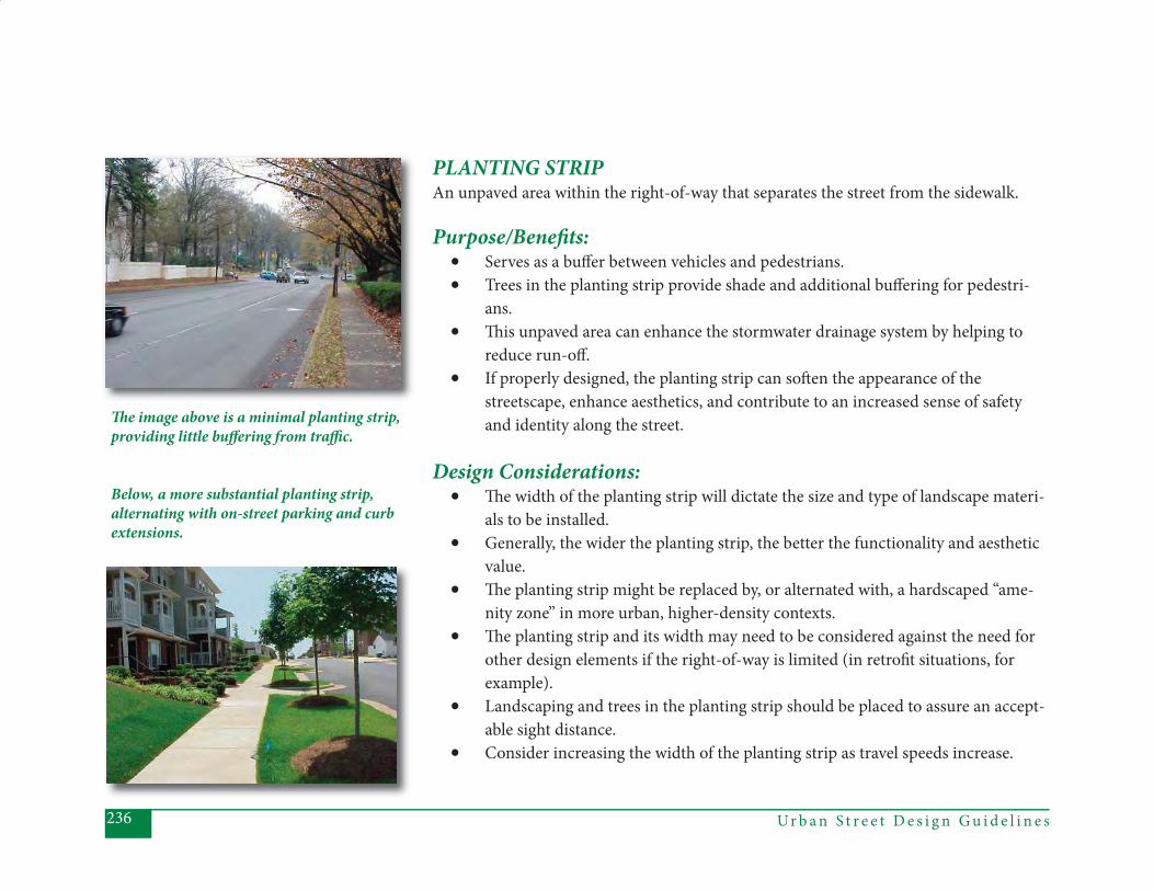
Ur b a n S t r e e t D e s i g n G u i d e l i n e s236
PLANTING STRIPAn unpaved area within the right-of-way that separates the street from the sidewalk.
Purpose/Benefi ts:• Serves as a buff er between vehicles and pedestrians.• Trees in the planting strip provide shade and additional buff ering for pedestri-
ans.• Th is unpaved area can enhance the stormwater drainage system by helping to
reduce run-off . • If properly designed, the planting strip can soft en the appearance of the
streetscape, enhance aesthetics, and contribute to an increased sense of safety and identity along the street.
Design Considerations: • Th e width of the planting strip will dictate the size and type of landscape materi-
als to be installed.• Generally, the wider the planting strip, the better the functionality and aesthetic
value.• Th e planting strip might be replaced by, or alternated with, a hardscaped “ame-
nity zone” in more urban, higher-density contexts. • Th e planting strip and its width may need to be considered against the need for
other design elements if the right-of-way is limited (in retrofi t situations, for example).
• Landscaping and trees in the planting strip should be placed to assure an accept-able sight distance.
• Consider increasing the width of the planting strip as travel speeds increase.
Th e image above is a minimal planting strip, providing little buff ering from traffi c.
Below, a more substantial planting strip, alternating with on-street parking and curb extensions.
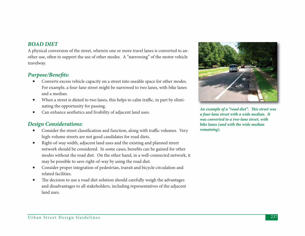
237Ur b a n S t r e e t D e s i g n G u i d e l i n e s
ROAD DIETA physical conversion of the street, wherein one or more travel lanes is converted to an-other use, oft en to support the use of other modes. A “narrowing” of the motor vehicle travelway.
Purpose/Benefi ts:• Converts excess vehicle capacity on a street into useable space for other modes.
For example, a four-lane street might be narrowed to two lanes, with bike lanes and a median.
• When a street is dieted to two lanes, this helps to calm traffi c, in part by elimi-nating the opportunity for passing.
• Can enhance aesthetics and livability of adjacent land uses.
Design Considerations: • Consider the street classifi cation and function, along with traffi c volumes. Very
high-volume streets are not good candidates for road diets.• Right-of-way width, adjacent land uses and the existing and planned street
network should be considered. In some cases, benefi ts can be gained for other modes without the road diet. On the other hand, in a well-connected network, it may be possible to save right-of-way by using the road diet.
• Consider proper integration of pedestrian, transit and bicycle circulation and related facilities.
• Th e decision to use a road diet solution should carefully weigh the advantages and disadvantages to all stakeholders, including representatives of the adjacent land uses.
An example of a “road diet”. Th is street was a four-lane street with a wide median. It was converted to a two-lane street, with bike lanes (and with the wide median remaining).
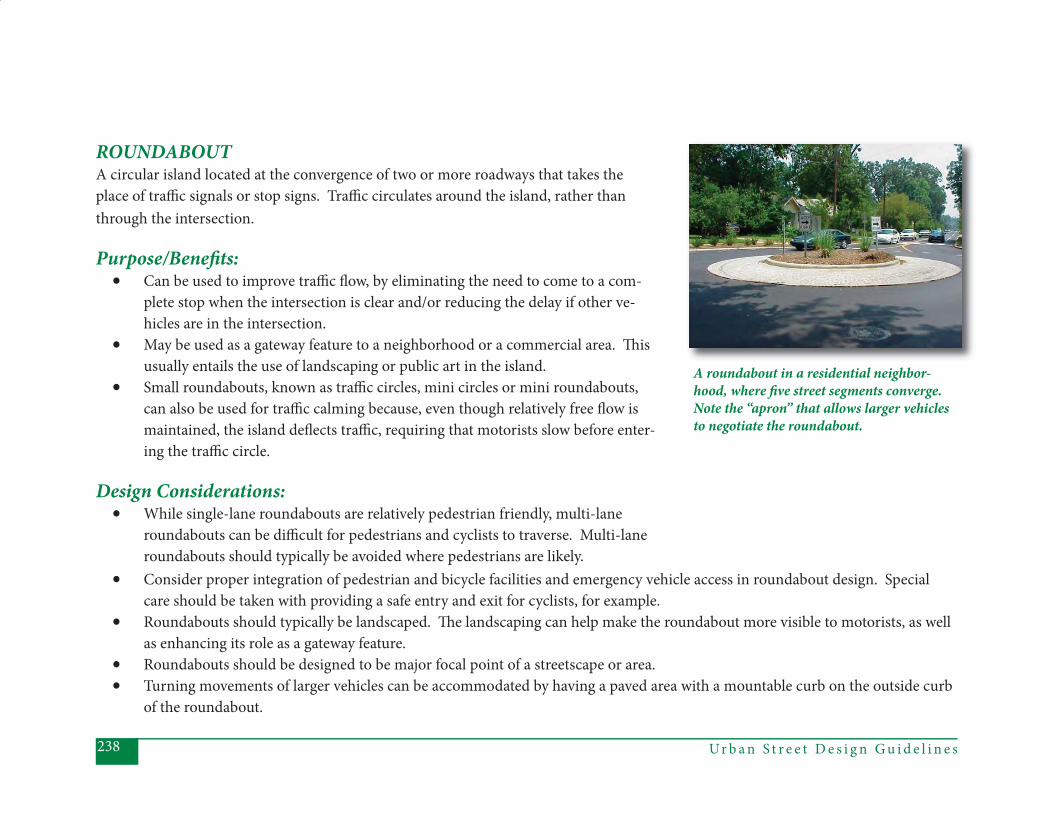
Ur b a n S t r e e t D e s i g n G u i d e l i n e s238
ROUNDABOUTA circular island located at the convergence of two or more roadways that takes the place of traffi c signals or stop signs. Traffi c circulates around the island, rather than through the intersection.
Purpose/Benefi ts:• Can be used to improve traffi c fl ow, by eliminating the need to come to a com-
plete stop when the intersection is clear and/or reducing the delay if other ve-hicles are in the intersection.
• May be used as a gateway feature to a neighborhood or a commercial area. Th is usually entails the use of landscaping or public art in the island.
• Small roundabouts, known as traffi c circles, mini circles or mini roundabouts, can also be used for traffi c calming because, even though relatively free fl ow is maintained, the island defl ects traffi c, requiring that motorists slow before enter-ing the traffi c circle.
Design Considerations: • While single-lane roundabouts are relatively pedestrian friendly, multi-lane
roundabouts can be diffi cult for pedestrians and cyclists to traverse. Multi-lane roundabouts should typically be avoided where pedestrians are likely.
A roundabout in a residential neighbor-hood, where fi ve street segments converge. Note the “apron” that allows larger vehicles to negotiate the roundabout.
• Consider proper integration of pedestrian and bicycle facilities and emergency vehicle access in roundabout design. Special care should be taken with providing a safe entry and exit for cyclists, for example.
• Roundabouts should typically be landscaped. Th e landscaping can help make the roundabout more visible to motorists, as well as enhancing its role as a gateway feature.
• Roundabouts should be designed to be major focal point of a streetscape or area.• Turning movements of larger vehicles can be accommodated by having a paved area with a mountable curb on the outside curb
of the roundabout.
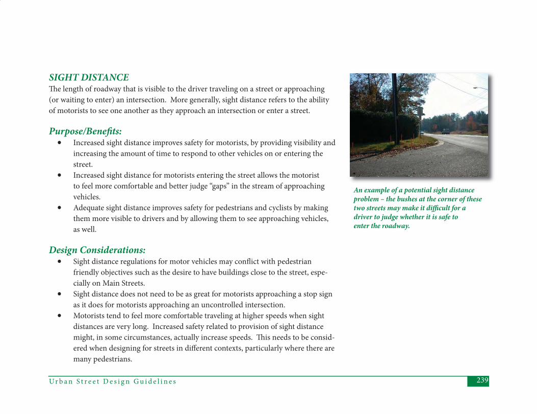
239Ur b a n S t r e e t D e s i g n G u i d e l i n e s
SIGHT DISTANCE Th e length of roadway that is visible to the driver traveling on a street or approaching (or waiting to enter) an intersection. More generally, sight distance refers to the ability of motorists to see one another as they approach an intersection or enter a street.
Purpose/Benefi ts:• Increased sight distance improves safety for motorists, by providing visibility and
increasing the amount of time to respond to other vehicles on or entering the street.
• Increased sight distance for motorists entering the street allows the motorist to feel more comfortable and better judge “gaps” in the stream of approaching vehicles.
• Adequate sight distance improves safety for pedestrians and cyclists by making them more visible to drivers and by allowing them to see approaching vehicles, as well.
Design Considerations:• Sight distance regulations for motor vehicles may confl ict with pedestrian
friendly objectives such as the desire to have buildings close to the street, espe-cially on Main Streets.
• Sight distance does not need to be as great for motorists approaching a stop sign as it does for motorists approaching an uncontrolled intersection.
• Motorists tend to feel more comfortable traveling at higher speeds when sight distances are very long. Increased safety related to provision of sight distance might, in some circumstances, actually increase speeds. Th is needs to be consid-ered when designing for streets in diff erent contexts, particularly where there are many pedestrians.
An example of a potential sight distance problem – the bushes at the corner of these two streets may make it diffi cult for a driver to judge whether it is safe to enter the roadway.
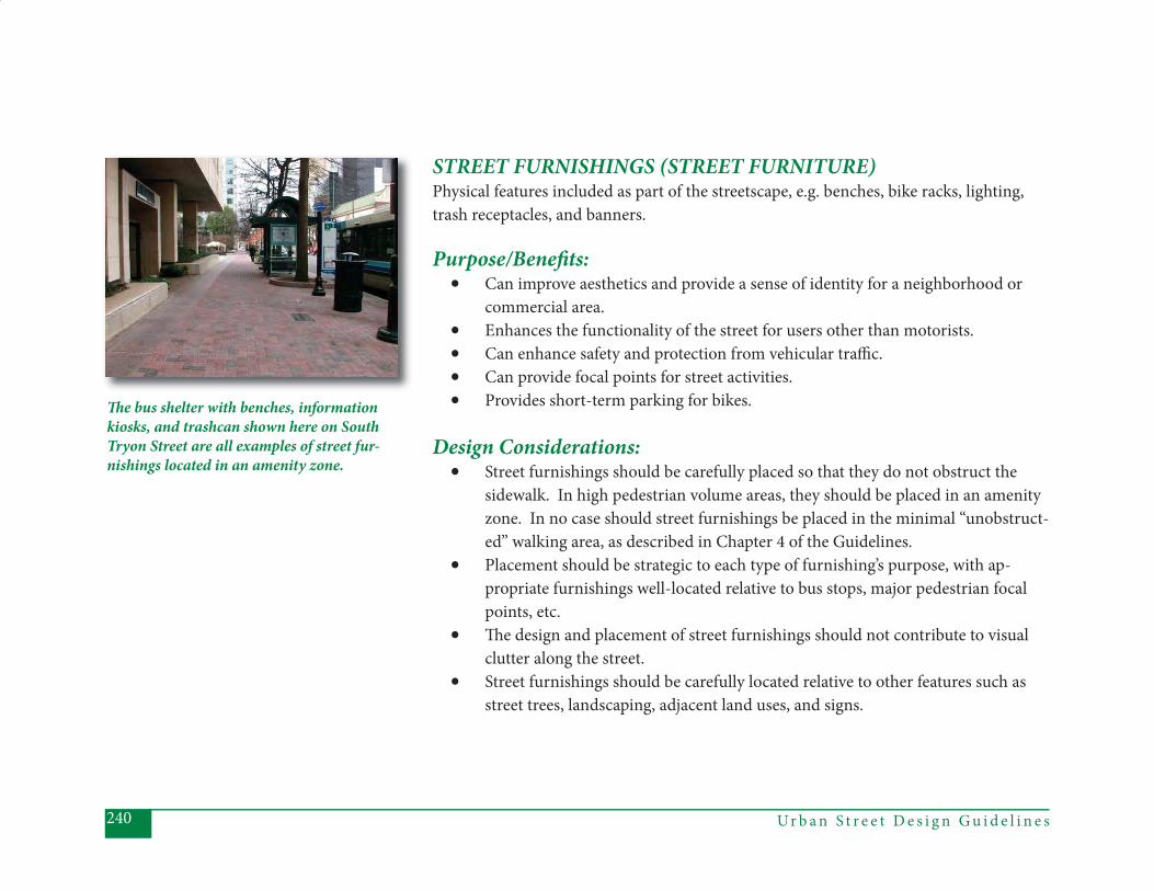
Ur b a n S t r e e t D e s i g n G u i d e l i n e s240
STREET FURNISHINGS (STREET FURNITURE)Physical features included as part of the streetscape, e.g. benches, bike racks, lighting, trash receptacles, and banners.
Purpose/Benefi ts:• Can improve aesthetics and provide a sense of identity for a neighborhood or
commercial area. • Enhances the functionality of the street for users other than motorists. • Can enhance safety and protection from vehicular traffi c.• Can provide focal points for street activities. • Provides short-term parking for bikes.
Design Considerations: • Street furnishings should be carefully placed so that they do not obstruct the
sidewalk. In high pedestrian volume areas, they should be placed in an amenity zone. In no case should street furnishings be placed in the minimal “unobstruct-ed” walking area, as described in Chapter 4 of the Guidelines.
• Placement should be strategic to each type of furnishing’s purpose, with ap-propriate furnishings well-located relative to bus stops, major pedestrian focal points, etc.
• Th e design and placement of street furnishings should not contribute to visual clutter along the street.
• Street furnishings should be carefully located relative to other features such as street trees, landscaping, adjacent land uses, and signs.
Th e bus shelter with benches, information kiosks, and trashcan shown here on South Tryon Street are all examples of street fur-nishings located in an amenity zone.
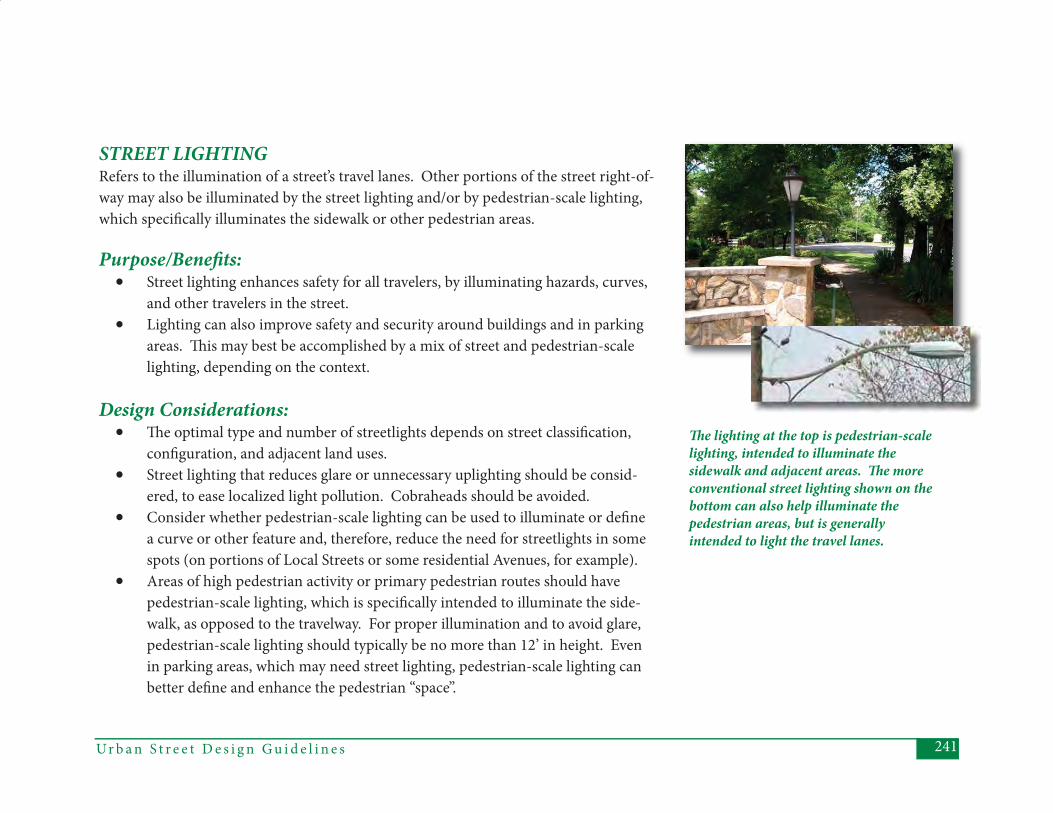
241Ur b a n S t r e e t D e s i g n G u i d e l i n e s
STREET LIGHTINGRefers to the illumination of a street’s travel lanes. Other portions of the street right-of-way may also be illuminated by the street lighting and/or by pedestrian-scale lighting, which specifi cally illuminates the sidewalk or other pedestrian areas.
Purpose/Benefi ts:• Street lighting enhances safety for all travelers, by illuminating hazards, curves,
and other travelers in the street.• Lighting can also improve safety and security around buildings and in parking
areas. Th is may best be accomplished by a mix of street and pedestrian-scale lighting, depending on the context.
Design Considerations:• Th e optimal type and number of streetlights depends on street classifi cation,
confi guration, and adjacent land uses. • Street lighting that reduces glare or unnecessary uplighting should be consid-
ered, to ease localized light pollution. Cobraheads should be avoided. • Consider whether pedestrian-scale lighting can be used to illuminate or defi ne
a curve or other feature and, therefore, reduce the need for streetlights in some spots (on portions of Local Streets or some residential Avenues, for example).
• Areas of high pedestrian activity or primary pedestrian routes should have pedestrian-scale lighting, which is specifi cally intended to illuminate the side-walk, as opposed to the travelway. For proper illumination and to avoid glare, pedestrian-scale lighting should typically be no more than 12’ in height. Even in parking areas, which may need street lighting, pedestrian-scale lighting can better defi ne and enhance the pedestrian “space”.
Th e lighting at the top is pedestrian-scale lighting, intended to illuminate the sidewalk and adjacent areas. Th e more conventional street lighting shown on the bottom can also help illuminate the pedestrian areas, but is generally intended to light the travel lanes.
Ur b a n S t r e e t D e s i g n G u i d e l i n e s242
STREETSCAPETh e combination of the physical elements installed within and along the street right-of-way that impact its usability, functionality, appearance and identity. Th e information contained in the Urban Street Design Guidelines (particularly Chapters 4 and 5) essen-tially describe how to develop the “streetscape”.
Purpose/Benefi ts:• Good streetscapes enhance a street’s functionality and aesthetics. • Good streetscapes enhance the community environment by providing access to
land uses, locations for social interaction, and sites for locating and maintaining infrastructure and amenities.
Design Considerations:• Th e appropriate combination of streetscape elements will vary according to
street classifi cation, right-of-way width, traffi c volume, land use context, and multi-modal expectations. Th ese variations are described in Chapters 4 and 5 of the Urban Street Design Guidelines.

243Ur b a n S t r e e t D e s i g n G u i d e l i n e s
TRAFFIC CALMINGOne or a combination of physical measures installed within the street right-of-way to slow or discourage traffi c along a street. Traffi c calming tools include curb extensions, chicanes, traffi c circles, speed humps (also called “speed tables”), raised crosswalks, landscaping, and paving treatments. See CDOT’s Traffi c Calming Report for a full dis-cussion of the types and appropriate application of traffi c calming devices.
Purpose/Benefi ts:• Modifi es traffi c patterns to reduce traffi c speeds.• Some forms of traffi c calming are used to reduce traffi c volumes either by elimi-
nating travel options entirely or by discouraging traffi c through signifi cant speed reductions. Th e intent of the tools and applications described in the Urban Street Design Guidelines and CDOT’s Traffi c Calming Report is to reduce speeds.
• Properly applied, can improve safety for all travelers by reducing speeds.• Properly applied, can improve liveability for those in the adjacent land uses, by
increasing safety and reducing noise, e.g..
Design Considerations:• Th e appropriate application of traffi c calming devices depends on street type,
traffi c volumes, current and desired speeds, street width, and existing traffi c control facilities and amenities. See CDOT’s Traffi c Calming Report for more information about which traffi c calming tools should be used under which cir-cumstances.
• Th e placement of traffi c calming items such as speed bumps and traffi c circles may impact drainage inlets.
Speed “humps” (or tables), such as those shown here, have been the typical approach to traffi c calming in Charlotte. Th e Urban Street Design Guidelines and related Traffi c Calming Report include additional options and the conditions under which they would be applied.
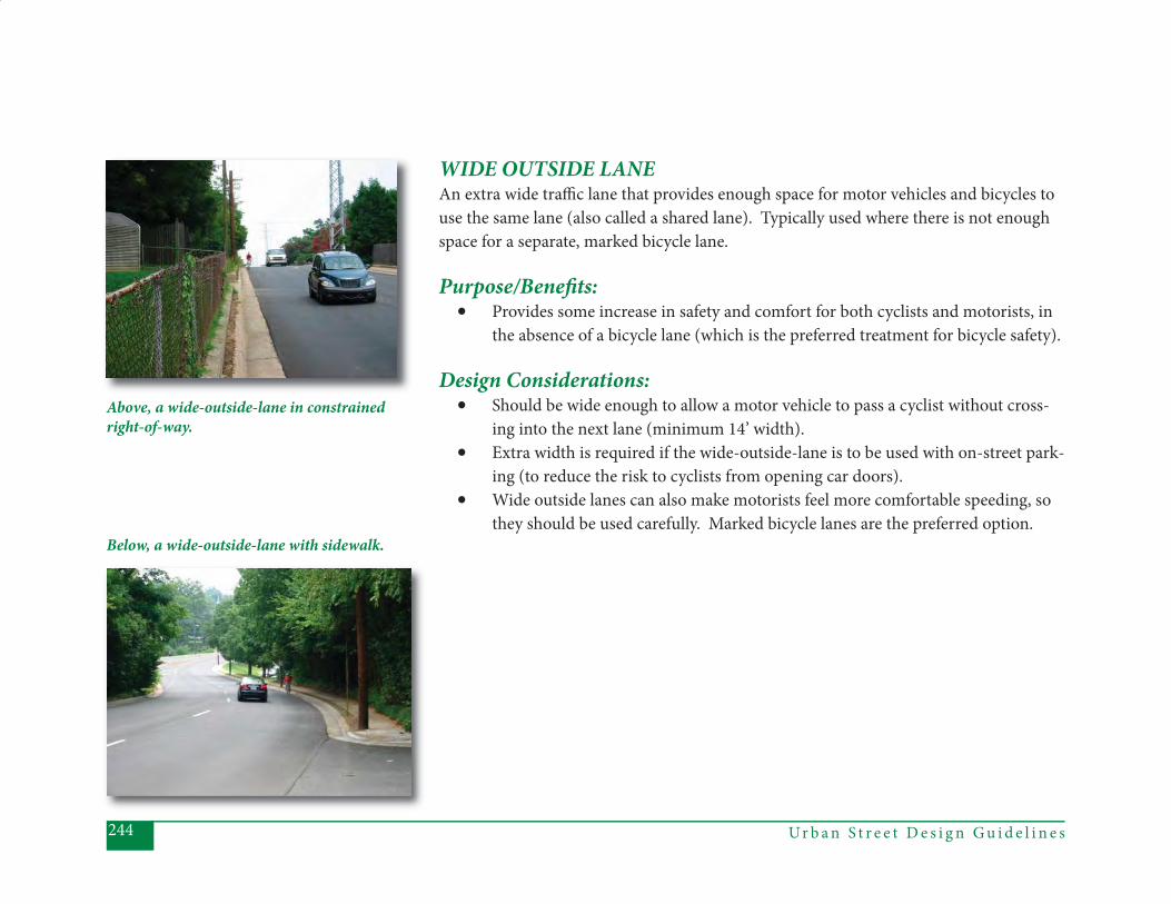
Ur b a n S t r e e t D e s i g n G u i d e l i n e s244
WIDE OUTSIDE LANEAn extra wide traffi c lane that provides enough space for motor vehicles and bicycles to use the same lane (also called a shared lane). Typically used where there is not enough space for a separate, marked bicycle lane.
Purpose/Benefi ts:• Provides some increase in safety and comfort for both cyclists and motorists, in
the absence of a bicycle lane (which is the preferred treatment for bicycle safety).
Design Considerations:• Should be wide enough to allow a motor vehicle to pass a cyclist without cross-
ing into the next lane (minimum 14’ width).• Extra width is required if the wide-outside-lane is to be used with on-street park-
ing (to reduce the risk to cyclists from opening car doors).• Wide outside lanes can also make motorists feel more comfortable speeding, so
they should be used carefully. Marked bicycle lanes are the preferred option.
Above, a wide-outside-lane in constrained right-of-way.
Below, a wide-outside-lane with sidewalk.
APPENDICES
Adopted by Charlotte City Council October 22, 2007

Appendix A
Planning and Designing Signalized Intersections Using Multi-Modal
Level-of-Service Standards

Appendix A: Planning and Designing Signalized Intersections Using Multi-Modal Level-of-Service Standards
This Appendix includes information necessary for evaluating Charlotte‟s signalized intersections from a multi-modal perspective. It includes 1) a brief introduction to Charlotte‟s new approach to intersection design, 2) a table and related notes to be used for evaluating and designing specific intersections, and 3) a step-by-step process for planning and defining intersection improvement projects in Charlotte. The intent of this information is to ensure that intersection design reflects the goals inherent in Charlotte‟s Urban Street Design Guidelines, specifically the desire to increase transportation choices by making travel by pedestrians, cyclists, and transit users safer and more convenient. Major changes to the evaluation procedure, as outlined below, include a two-hour standard for evaluating motor vehicle “level-of-service” (LOS) at an intersection, and the inclusion of a pedestrian and a bicycle LOS standard. As shown on Table 1, the volume/capacity (V/C) ratio of a signalized intersection is used as a surrogate for motor vehicle LOS and as a threshold or trigger to investigate any operational or physical capacity increases at the intersection. The “conditions” listed are directly related to the street classification(s) at the intersection, as defined by the Urban Street Design Guidelines. In general, the more pedestrian-oriented the intersection classification, the more stringent the V/C threshold condition. The inclusion of a two hour V/C threshold condition for most street types is a major departure from the previous method used by CDOT to evaluate intersections and is intended to ensure a context-sensitive, multi-modal approach to planning and designing intersection “improvements”. Note that signalized driveways should be evaluated as if they are Local Streets. The V/C ratio must also be balanced against the level-of-service (LOS) expected for pedestrians and cyclists for a given intersection type, which is another major departure from the traditional approach to intersection planning and design. Both LOS methodologies were developed by CDOT for use at all signalized intersections. The LOS ratings shown on Table 1 are objectives to strive for when designing or re-designing an intersection. A detailed description of the LOS methodology for pedestrians and bicyclists is provided in Appendix B. Finally, there are several steps that should be taken before any physical capacity increases are provided. For the analysis of existing motor vehicle operating conditions, multiple year trends should be analyzed. Capacity increases would be considered when:
the above thresholds are met for multiple years, operational solutions are analyzed and deemed unworkable, and additional connections/route options are also investigated.
Once these steps are taken, then physical capacity increases for motorists would be considered, in conjunction with whatever physical and design features would be necessary to maintain the pedestrian and bicycle LOS, as shown on Table 1.
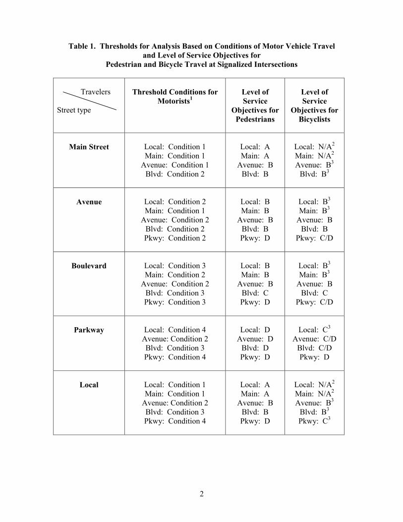
2
Table 1. Thresholds for Analysis Based on Conditions of Motor Vehicle Travel and Level of Service Objectives for
Pedestrian and Bicycle Travel at Signalized Intersections
Travelers Street type
Threshold Conditions for
Motorists1
Level of Service
Objectives for Pedestrians
Level of Service
Objectives for Bicyclists
Main Street
Local: Condition 1 Main: Condition 1
Avenue: Condition 1 Blvd: Condition 2
Local: A Main: A
Avenue: B Blvd: B
Local: N/A2 Main: N/A2 Avenue: B3
Blvd: B3
Avenue
Local: Condition 2 Main: Condition 1
Avenue: Condition 2 Blvd: Condition 2 Pkwy: Condition 2
Local: B Main: B
Avenue: B Blvd: B Pkwy: D
Local: B3 Main: B3
Avenue: B Blvd: B
Pkwy: C/D
Boulevard
Local: Condition 3 Main: Condition 2
Avenue: Condition 2 Blvd: Condition 3 Pkwy: Condition 3
Local: B Main: B
Avenue: B Blvd: C Pkwy: D
Local: B3 Main: B3
Avenue: B Blvd: C
Pkwy: C/D
Parkway
Local: Condition 4
Avenue: Condition 2 Blvd: Condition 3 Pkwy: Condition 4
Local: D
Avenue: D Blvd: D Pkwy: D
Local: C3
Avenue: C/D Blvd: C/D Pkwy: D
Local
Local: Condition 1 Main: Condition 1
Avenue: Condition 2 Blvd: Condition 3 Pkwy: Condition 4
Local: A Main: A
Avenue: B Blvd: B Pkwy: D
Local: N/A2 Main: N/A2 Avenue: B3
Blvd: B3 Pkwy: C3
3
1 These conditions (existing or projected) for vehicular travel at signalized intersections establish the thresholds for proceeding with the analysis of levels-of-service (LOS) for motor vehicle, pedestrian and bicycle travel. 2 The application of the CDOT bicycle LOS methodology is not recommended for intersections of Local or Main streets. The methodology assigns high positive values to the separation of bicyclists from motor vehicles, specifically by bike lanes and/or bike boxes. Local and Main streets do not need bike lanes because they are generally comfortable and safe for most cyclists. 3 Intersections of this type shall be analyzed based on the averages of only the Avenue, Boulevard, or Parkway approaches. For example, when analyzing the intersection of a Main street and a Boulevard, the two values obtained for the Boulevard approaches should be averaged. Defined Threshold Conditions Condition 1: V/C (volume/capacity) >= 1.0, for two consecutive AM or PM hours Condition 2: V/C (volume/capacity) >= 0.95, for two consecutive AM or PM hours Condition 3: V/C (volume/capacity) >= 0.95, for BOTH one AM and PM hour Condition 4: V/C (volume/capacity) >= 0.90, for BOTH one AM and PM hour
Applying LOS Standards to Project Definition The previous discussion describes the new philosophy of and standards for intersection design for the City of Charlotte. The following steps describe the appropriate application of that philosophy to planning and, specifically, to defining intersection projects based on the Street Design Guidelines‟ recommendations.
1. Analyze all signalized intersections for am and pm peak hour traffic operational
conditions, and for accident trends and problems.
2. Based on the analysis of operational conditions and accident data, develop initial list of locations that could include traffic congestion and/or safety mitigation measures.
3. Calculate pedestrian and bicycle LOS for current operating and design conditions
for the intersections that appear on the list in step two.
4. Define ways that those intersections can be improved for autos by operational changes alone and those that require roadway changes (i.e., widenings).
5. If two or more intersections in the vicinity are classified for possible changes that
affect pedestrian and bicycle LOS, the scope of analysis will be expanded to include the arterial corridor or an area.
6. When operational changes alone can be made to improve auto level of service at
signalized intersections, CDOT staff will proceed with implementing those changes – provided those changes do not worsen pedestrian and/or bicyclist level
4
of service for crossing those intersections. If operational changes will result in degradation to pedestrian and/or bicyclist level of service, then Systems Division personnel will meet with Planning Division personnel (e.g., pedestrian and bike planners) before implementing changes. Personnel responsible for phasing and/or signal timing modifications will identify and try to mitigate those conditions in the Pedestrian and Bicyclists Level of Service Methodology that worsen pedestrian and bicyclist level of service.
7. If it is determined that operational changes alone will not affect auto level of
service, then additional capacity analyses will be performed based on an expanded time period - beyond the am and pm peak hours analyzed in step one. The number of hours to be analyzed will vary according to the level of service standards set forth in the street design guidelines. For locations that meet or exceed these standards, solutions that provide improved auto level of service may be developed, provided pedestrian and bicyclist level of service are not worsened. Staff from both the Planning Division and Systems Division will work together to develop possible project alternatives.
Appendix B
Method for Determining Pedestrian and Bicycle LOS at
Signalized Intersections

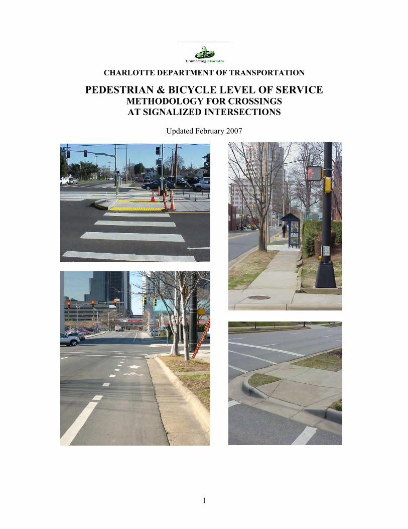
1
CHARLOTTE DEPARTMENT OF TRANSPORTATION
PEDESTRIAN & BICYCLE LEVEL OF SERVICE METHODOLOGY FOR CROSSINGS AT SIGNALIZED INTERSECTIONS
Updated February 2007
2
CONTENTS Introduction ………………………………………………………………… p 3 Signal Features and Pedestrian Level of Service …………………………... p 3 Signal Features and Bicycle Level of Service ……………………………… p 6 Pedestrian and Bicycle Level of Service Determination …………………… p 9 Summary …………………………………………………………………… p 9 Pedestrian Level of Service Calculation Tables …………………………… p 11 Bicycle Level of Service Calculation Tables ……………………………… p 16 Intersection Example #1 ……………………………….………………….. p 19 Intersection Example #2 ……………………………….………………….. p 22 TABLES AND FIGURES Table 1 Pedestrian LOS: Crossing Distance ……………………………. p 11 Table 2 Pedestrian LOS: Signal Phasing & Timing Features …………... p 12, 13 Table 3 Pedestrian LOS: Corner Radius ………………………………... p 14 Table 4 Pedestrian LOS: Right Turns On Red …………………………. p 15 Table 5 Pedestrian LOS: Crosswalk Treatment ………………………… p 15 Table 6 Pedestrian LOS: Adjustment for One-Way Street Crossings .…. p 15 Table 7 Point Totals and Corresponding Pedestrian Level of Service …. p 15 Table 8 Bicycle LOS: Bicycle Travel Way & Speed of Adjacent Traffic p 16, 17 Table 9 Bicycle LOS: Signal Features – Left Turns & Stop Bar Location p 17 Table 10 Bicycle LOS: Right Turn Traffic Conflict .……..……………... p 18 Table 11 Bicycle LOS: Right Turns On Red ……………………………. p 18 Table 12 Bicycle LOS: Intersection Crossing Distance …………………. p 18 Table 13 Point Totals and Corresponding Bicycle Level of Service ……. p 18 Figure 1 Pedestrian Crossing Conflicts …………………………………. p 5 Figure 2 Corner Channel Island Designs ……………………………….. p 5 Figure 3 Adjustment for One-Way Streets … ………………………….. p 6 Figure 4 Bicycle Crossing Conflicts ……………………………………. p 7 Figure 5 Bike Treatments at Exclusive Right Turn Lanes ..…………….. p 8 Figure 6 Example Intersection #1: Pedestrian LOS Calculation ……….. p 20 Figure 7 Example Intersection #1: Bicycle LOS Calculation ………….. p 21 Figure 8 Example Intersection #2: Pedestrian LOS Calculation ………. p 23

3
INTRODUCTION
The Charlotte Department of Transportation has developed the following methodology to assess the important design features that affect pedestrians and bicyclists crossing signalized intersections. Referred to as Level of Service (LOS), this methodology identifies and evaluates features according to their influence on the comfort and safety of pedestrians and bicyclists. Among the key features identified and rated are crossing distance, roadway space allocation (i.e., crosswalks, bike lanes), corner radius dimension and traffic signal characteristics.
This methodology can be used as a diagnostic tool to assess and improve pedestrian and bicyclist levels of comfort and safety by modifying design and operational features of intersections. The results can be compared with those for traffic levels of service of an intersection and weighed according to user priorities. This methodology is intended to be used to select design and operational features that can help achieve desired levels of service for pedestrians and bicyclists. SIGNALIZED INTERSECTION FEATURES AND THEIR RELATIVE IMPORTANCE TO PEDESTRIAN LEVEL OF SERVICE (LOS) The primary impediments to comfort and safety for pedestrians crossing at signalized intersections are crossing distance and conflicts with turning vehicles. Vehicle volumes and speeds are factors as well, but are tempered by the presence of the traffic signal, its phasing, and/or physical characteristics of the intersection. For example, tight corner radii can slow the speeds of right-turning vehicles, and right and left turn conflicts can be reduced or eliminated by signal phasing, all design factors affecting comfort and safety between pedestrians and vehicles. So although volumes and speeds are not explicitly addressed by this methodology, they are implicitly dealt with.
This approach for assessing pedestrian level of service, therefore, identifies those key elements or features of intersections that enhance or reduce comfort and safety, and then weighs them relative to one another by a point system. Points are assigned to physical and operational features of intersections according to how well they achieve these objectives. These important features are discussed below. Rated Intersection Features Crossing Distance (Table 1) – As previously mentioned, crossing distance is the primary crossing component or obstacle for pedestrians traveling across intersections and therefore receives the greatest weight in this methodology. The less distance one has to walk to cross a street, the easier and more comfortable it is perceived to be. A crossing equivalent to two or three lanes, for example, rates a minimum LOS of B, exclusive of any other features. By contrast, a crossing of eight lanes or more falls in the LOS F range, exclusive of other features. For wide street crossings, where there is a greater probability that pedestrians might fail to make it across the entire roadway during a signal phase, level of service can be improved noticeably if there is a median wide enough to
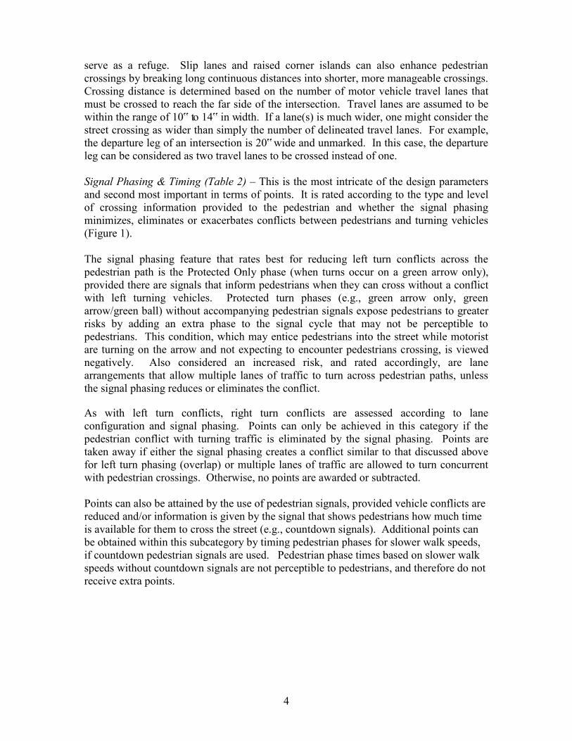
4
serve as a refuge. Slip lanes and raised corner islands can also enhance pedestrian crossings by breaking long continuous distances into shorter, more manageable crossings. Crossing distance is determined based on the number of motor vehicle travel lanes that must be crossed to reach the far side of the intersection. Travel lanes are assumed to be within the range of 10‟ to 14‟ in width. If a lane(s) is much wider, one might consider the street crossing as wider than simply the number of delineated travel lanes. For example, the departure leg of an intersection is 20‟ wide and unmarked. In this case, the departure leg can be considered as two travel lanes to be crossed instead of one. Signal Phasing & Timing (Table 2) – This is the most intricate of the design parameters and second most important in terms of points. It is rated according to the type and level of crossing information provided to the pedestrian and whether the signal phasing minimizes, eliminates or exacerbates conflicts between pedestrians and turning vehicles (Figure 1). The signal phasing feature that rates best for reducing left turn conflicts across the pedestrian path is the Protected Only phase (when turns occur on a green arrow only), provided there are signals that inform pedestrians when they can cross without a conflict with left turning vehicles. Protected turn phases (e.g., green arrow only, green arrow/green ball) without accompanying pedestrian signals expose pedestrians to greater risks by adding an extra phase to the signal cycle that may not be perceptible to pedestrians. This condition, which may entice pedestrians into the street while motorist are turning on the arrow and not expecting to encounter pedestrians crossing, is viewed negatively. Also considered an increased risk, and rated accordingly, are lane arrangements that allow multiple lanes of traffic to turn across pedestrian paths, unless the signal phasing reduces or eliminates the conflict. As with left turn conflicts, right turn conflicts are assessed according to lane configuration and signal phasing. Points can only be achieved in this category if the pedestrian conflict with turning traffic is eliminated by the signal phasing. Points are taken away if either the signal phasing creates a conflict similar to that discussed above for left turn phasing (overlap) or multiple lanes of traffic are allowed to turn concurrent with pedestrian crossings. Otherwise, no points are awarded or subtracted. Points can also be attained by the use of pedestrian signals, provided vehicle conflicts are reduced and/or information is given by the signal that shows pedestrians how much time is available for them to cross the street (e.g., countdown signals). Additional points can be obtained within this subcategory by timing pedestrian phases for slower walk speeds, if countdown pedestrian signals are used. Pedestrian phase times based on slower walk speeds without countdown signals are not perceptible to pedestrians, and therefore do not receive extra points.
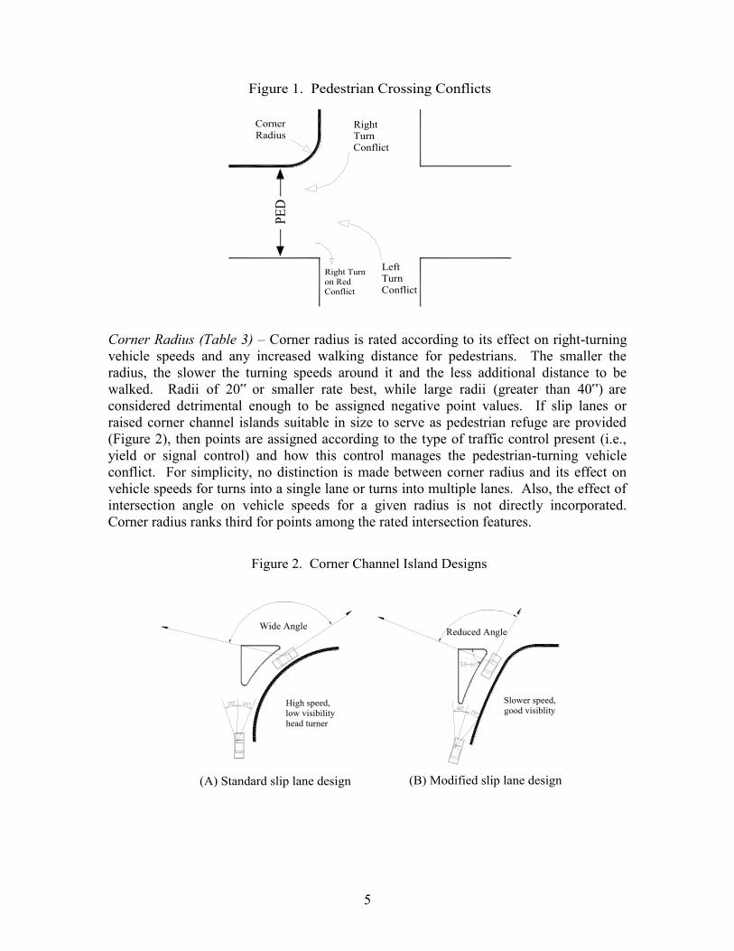
5
PED
Figure 1. Pedestrian Crossing Conflicts
Right Turn Conflict
Corner Radius
Left Turn Conflict
Right Turn on Red Conflict
Corner Radius (Table 3) – Corner radius is rated according to its effect on right-turning vehicle speeds and any increased walking distance for pedestrians. The smaller the radius, the slower the turning speeds around it and the less additional distance to be walked. Radii of 20‟ or smaller rate best, while large radii (greater than 40‟) are considered detrimental enough to be assigned negative point values. If slip lanes or raised corner channel islands suitable in size to serve as pedestrian refuge are provided (Figure 2), then points are assigned according to the type of traffic control present (i.e., yield or signal control) and how this control manages the pedestrian-turning vehicle conflict. For simplicity, no distinction is made between corner radius and its effect on vehicle speeds for turns into a single lane or turns into multiple lanes. Also, the effect of intersection angle on vehicle speeds for a given radius is not directly incorporated. Corner radius ranks third for points among the rated intersection features.
Figure 2. Corner Channel Island Designs
Wide Angle Reduced Angle
(A) Standard slip lane design (B) Modified slip lane design
Slower speed, good visiblity
High speed, low visibility head turner
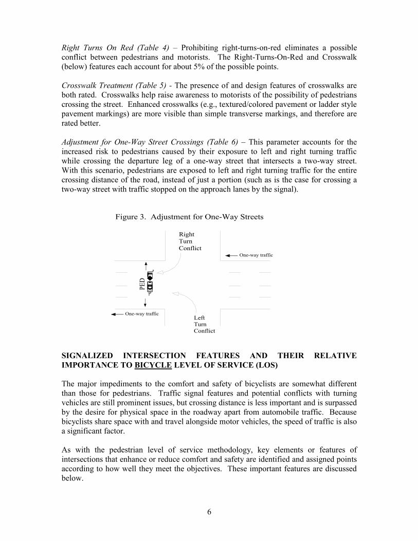
6
Right Turns On Red (Table 4) – Prohibiting right-turns-on-red eliminates a possible conflict between pedestrians and motorists. The Right-Turns-On-Red and Crosswalk (below) features each account for about 5% of the possible points. Crosswalk Treatment (Table 5) - The presence of and design features of crosswalks are both rated. Crosswalks help raise awareness to motorists of the possibility of pedestrians crossing the street. Enhanced crosswalks (e.g., textured/colored pavement or ladder style pavement markings) are more visible than simple transverse markings, and therefore are rated better. Adjustment for One-Way Street Crossings (Table 6) – This parameter accounts for the increased risk to pedestrians caused by their exposure to left and right turning traffic while crossing the departure leg of a one-way street that intersects a two-way street. With this scenario, pedestrians are exposed to left and right turning traffic for the entire crossing distance of the road, instead of just a portion (such as is the case for crossing a two-way street with traffic stopped on the approach lanes by the signal).
One-way traffic
One-way traffic
RightTurnConflict
LeftTurnConflict
P
ED
Figure 3. Adjustment for One-Way Streets
SIGNALIZED INTERSECTION FEATURES AND THEIR RELATIVE IMPORTANCE TO BICYCLE LEVEL OF SERVICE (LOS) The major impediments to the comfort and safety of bicyclists are somewhat different than those for pedestrians. Traffic signal features and potential conflicts with turning vehicles are still prominent issues, but crossing distance is less important and is surpassed by the desire for physical space in the roadway apart from automobile traffic. Because bicyclists share space with and travel alongside motor vehicles, the speed of traffic is also a significant factor.
As with the pedestrian level of service methodology, key elements or features of intersections that enhance or reduce comfort and safety are identified and assigned points according to how well they meet the objectives. These important features are discussed below.
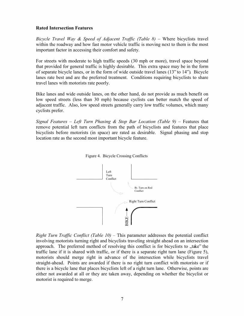
7
Rated Intersection Features Bicycle Travel Way & Speed of Adjacent Traffic (Table 8) – Where bicyclists travel within the roadway and how fast motor vehicle traffic is moving next to them is the most important factor in accessing their comfort and safety. For streets with moderate to high traffic speeds (30 mph or more), travel space beyond that provided for general traffic is highly desirable. This extra space may be in the form of separate bicycle lanes, or in the form of wide outside travel lanes (13‟ to 14‟). Bicycle lanes rate best and are the preferred treatment. Conditions requiring bicyclists to share travel lanes with motorists rate poorly. Bike lanes and wide outside lanes, on the other hand, do not provide as much benefit on low speed streets (less than 30 mph) because cyclists can better match the speed of adjacent traffic. Also, low speed streets generally carry low traffic volumes, which many cyclists prefer. Signal Features – Left Turn Phasing & Stop Bar Location (Table 9) – Features that remove potential left turn conflicts from the path of bicyclists and features that place bicyclists before motorists (in space) are rated as desirable. Signal phasing and stop location rate as the second most important bicycle feature.
LeftTurnConflict
Rt. Turn on RedConflict
Right Turn Conflict
Figure 4. Bicycle Crossing Conflicts
BIK
E
Right Turn Traffic Conflict (Table 10) – This parameter addresses the potential conflict involving motorists turning right and bicyclists traveling straight ahead on an intersection approach. The preferred method of resolving this conflict is for bicyclists to „take‟ the traffic lane if it is shared with traffic, or if there is a separate right turn lane (Figure 5), motorists should merge right in advance of the intersection while bicyclists travel straight-ahead. Points are awarded if there is no right turn conflict with motorists or if there is a bicycle lane that places bicyclists left of a right turn lane. Otherwise, points are either not awarded at all or they are taken away, depending on whether the bicyclist or motorist is required to merge.
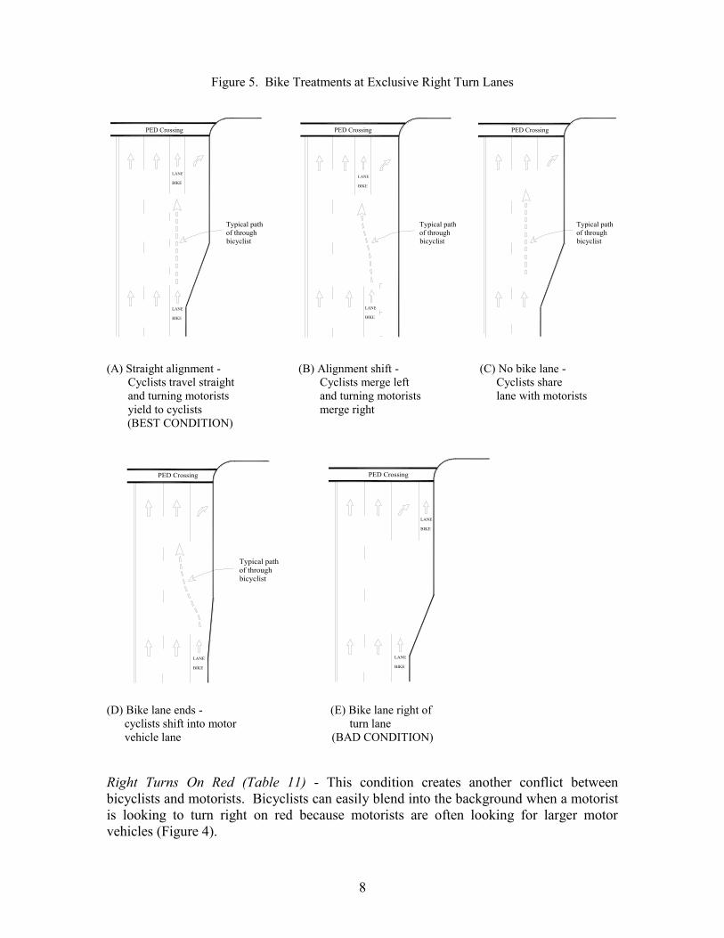
8
Figure 5. Bike Treatments at Exclusive Right Turn Lanes
LANE
BIKE
PED Crossing
LANE
BIKELANE
BIKE
LANE
BIKE
Typical pathof throughbicyclist
Typical pathof throughbicyclist
Typical pathof throughbicyclist
PED Crossing PED Crossing
(A) Straight alignment - (B) Alignment shift - (C) No bike lane - Cyclists travel straight Cyclists merge left Cyclists share and turning motorists and turning motorists lane with motorists yield to cyclists merge right (BEST CONDITION)
LANE
BIKE
LANE
BIKE
LANE
BIKE
PED Crossing PED Crossing
Typical pathof throughbicyclist
(D) Bike lane ends - (E) Bike lane right of cyclists shift into motor turn lane vehicle lane (BAD CONDITION) Right Turns On Red (Table 11) - This condition creates another conflict between bicyclists and motorists. Bicyclists can easily blend into the background when a motorist is looking to turn right on red because motorists are often looking for larger motor vehicles (Figure 4).
9
Crossing Distance (Table 12) – Wide street crossings increase the risk of exposure to bicyclists from motor vehicle traffic on cross-streets. Signal clearance times (the yellow and all-red signal phase portions) are timed for motor vehicle speeds and not the slower speeds of bicyclists; therefore, the wider the intersection, the greater the likelihood that cyclists will still be crossing when right-of-way changes to the cross-street. Intersection Features Not Rated in the Pedestrian and Bicycle Methodologies There are several other features not rated in these methodologies that also affect the comfort and safety of pedestrians and bicyclists and should be considered in intersection design. Among these features are sight lines, street lighting, pavement condition, signing, pedestrian and bike detection, curb extensions, and ADA features such as wheel chair ramps and accessible signals.
PEDESTRIAN AND BICYCLE LOS DETERMINATION Level of service for an intersection crossing/approach is determined by adding points from Tables 1 through 6 (for Pedestrians) and points from Tables 8 through 12 (for Bicyclists). The accumulation of points is then compared to the points listed in Tables 7 (Pedestrians) and 13 (Bicyclists), which provides the threshold values for levels of service A through F. An overall intersection level of service for either pedestrian or bicycle features can also be determined by adding the total points from each crossing and dividing their sum by the number of intersection crossing legs (e. g., a three leg intersection‟s point totals would be divided by three). The higher the point total, the better the level of service. SUMMARY The level of service methodology is intended to be used to assess the most crucial, especially safety related, factors affecting pedestrians‟ and bicyclists‟ crossing signalized intersections. It attempts to identify and compare those design elements that help make intersection crossings safer and pedestrians and bicyclists feel more comfortable. The methodology is not concerned with the quality of the environment away from the intersection crossing, so those elements that make an area more inviting and attractive to pedestrians and bicyclists, such as visual stimuli, convenience, security, and noise are not considered. These other elements and their importance on creating a pedestrian and bicycle friendly environment are addressed through initiatives such as the Urban Street Design Guidelines The focus of this methodology is on those intersection features that reduce traffic conflicts, minimize crossing distances, slow down traffic speeds and raise user awareness. The methodology assumes that all rated features are adequately designed and implemented (e.g., signals are timed adequately and pedestrian signals are well placed), so that equivalent comparisons can be made between features. While important to the overall sense of safety and comfort, elements of risk (e.g., traffic volumes) are not directly evaluated in the methodology since design features are the focus and design features can be used to mitigate the effects of risks. Furthermore, design features such as
10
cross-section distance, number and type of travel lanes, and signal-phasing schemes typically reflect varying traffic volumes. This level of service methodology is expected to be applied in conjunction with the traditional level of service methodology for motor vehicles. The importance or relative weight given to each level of service (for motor vehicles, bicyclists or pedestrians) is expected to vary by intersection, depending on the planned function and context of each intersection. The following pages provide additional detail of the pedestrian and bicycle level of service methodologies, along with example level of service calculations. As a companion piece to this document, Charlotte DOT has also developed an electronic spreadsheet that can be used to quickly calculate levels of service. The spreadsheet should be used when performing level of service calculations.
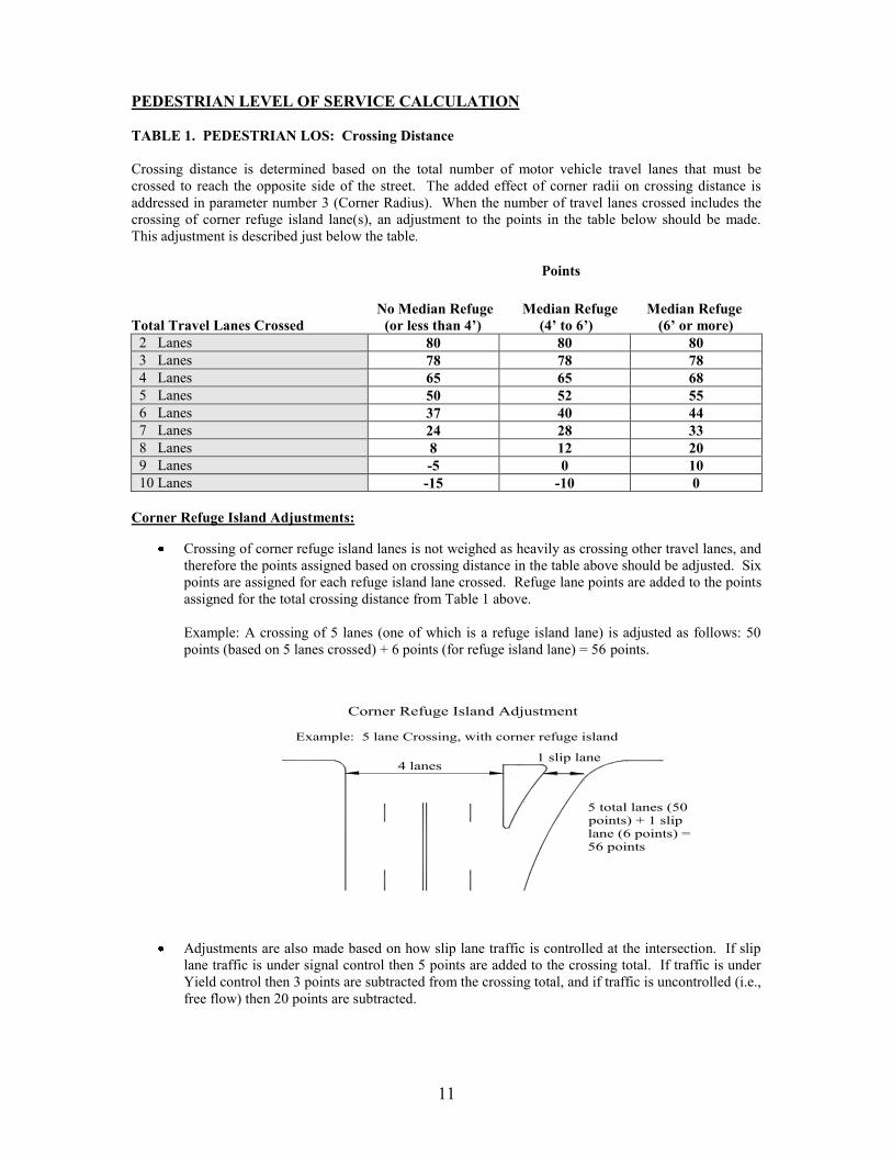
11
PEDESTRIAN LEVEL OF SERVICE CALCULATION TABLE 1. PEDESTRIAN LOS: Crossing Distance Crossing distance is determined based on the total number of motor vehicle travel lanes that must be crossed to reach the opposite side of the street. The added effect of corner radii on crossing distance is addressed in parameter number 3 (Corner Radius). When the number of travel lanes crossed includes the crossing of corner refuge island lane(s), an adjustment to the points in the table below should be made. This adjustment is described just below the table.
Points No Median Refuge Median Refuge Median Refuge Total Travel Lanes Crossed (or less than 4’) (4’ to 6’) (6’ or more)
2 Lanes 80 80 80 3 Lanes 78 78 78 4 Lanes 65 65 68 5 Lanes 50 52 55 6 Lanes 37 40 44 7 Lanes 24 28 33 8 Lanes 8 12 20 9 Lanes -5 0 10 10 Lanes -15 -10 0
Corner Refuge Island Adjustments:
Crossing of corner refuge island lanes is not weighed as heavily as crossing other travel lanes, and therefore the points assigned based on crossing distance in the table above should be adjusted. Six points are assigned for each refuge island lane crossed. Refuge lane points are added to the points assigned for the total crossing distance from Table 1 above.
Example: A crossing of 5 lanes (one of which is a refuge island lane) is adjusted as follows: 50 points (based on 5 lanes crossed) + 6 points (for refuge island lane) = 56 points.
Example: 5 lane Crossing, with corner refuge island
1 slip lane4 lanes
Corner Refuge Island Adjustment
5 total lanes (50points) + 1 sliplane (6 points) =56 points
Adjustments are also made based on how slip lane traffic is controlled at the intersection. If slip
lane traffic is under signal control then 5 points are added to the crossing total. If traffic is under Yield control then 3 points are subtracted from the crossing total, and if traffic is uncontrolled (i.e., free flow) then 20 points are subtracted.
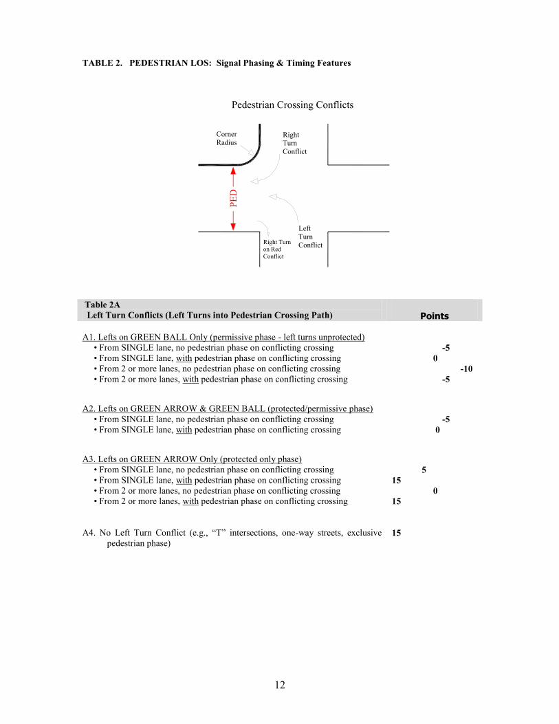
12
TABLE 2. PEDESTRIAN LOS: Signal Phasing & Timing Features
Pedestrian Crossing Conflicts
CornerRadius
RightTurnConflict
PED
LeftTurnConflictRight Turn
on RedConflict
Table 2A Left Turn Conflicts (Left Turns into Pedestrian Crossing Path)
Points
A1. Lefts on GREEN BALL Only (permissive phase - left turns unprotected) • From SINGLE lane, no pedestrian phase on conflicting crossing • From SINGLE lane, with pedestrian phase on conflicting crossing • From 2 or more lanes, no pedestrian phase on conflicting crossing • From 2 or more lanes, with pedestrian phase on conflicting crossing
-5 0 -10 -5
A2. Lefts on GREEN ARROW & GREEN BALL (protected/permissive phase) • From SINGLE lane, no pedestrian phase on conflicting crossing • From SINGLE lane, with pedestrian phase on conflicting crossing
-5 0
A3. Lefts on GREEN ARROW Only (protected only phase) • From SINGLE lane, no pedestrian phase on conflicting crossing • From SINGLE lane, with pedestrian phase on conflicting crossing • From 2 or more lanes, no pedestrian phase on conflicting crossing • From 2 or more lanes, with pedestrian phase on conflicting crossing
5 15 0 15
A4. No Left Turn Conflict (e.g., “T” intersections, one-way streets, exclusive
pedestrian phase)
15
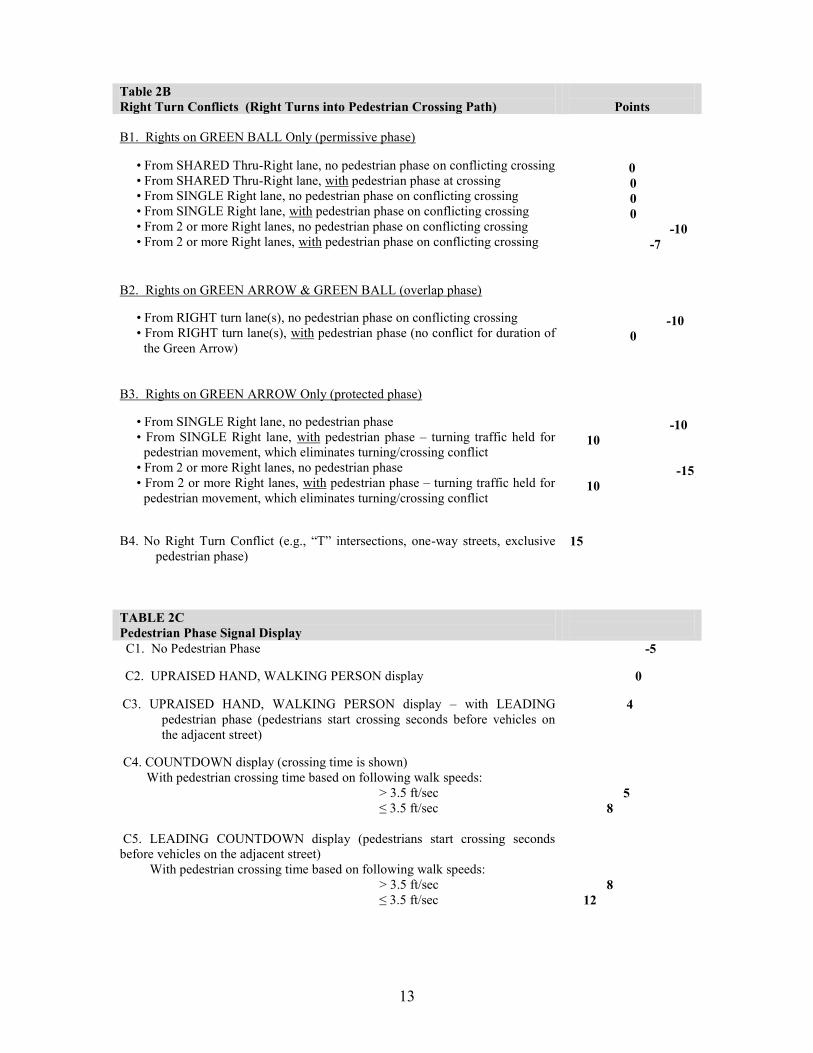
13
Table 2B Right Turn Conflicts (Right Turns into Pedestrian Crossing Path)
Points
B1. Rights on GREEN BALL Only (permissive phase)
• From SHARED Thru-Right lane, no pedestrian phase on conflicting crossing • From SHARED Thru-Right lane, with pedestrian phase at crossing • From SINGLE Right lane, no pedestrian phase on conflicting crossing • From SINGLE Right lane, with pedestrian phase on conflicting crossing • From 2 or more Right lanes, no pedestrian phase on conflicting crossing • From 2 or more Right lanes, with pedestrian phase on conflicting crossing
0 0 0 0 -10 -7
B2. Rights on GREEN ARROW & GREEN BALL (overlap phase) • From RIGHT turn lane(s), no pedestrian phase on conflicting crossing • From RIGHT turn lane(s), with pedestrian phase (no conflict for duration of
the Green Arrow)
-10 0
B3. Rights on GREEN ARROW Only (protected phase) • From SINGLE Right lane, no pedestrian phase • From SINGLE Right lane, with pedestrian phase – turning traffic held for
pedestrian movement, which eliminates turning/crossing conflict • From 2 or more Right lanes, no pedestrian phase • From 2 or more Right lanes, with pedestrian phase – turning traffic held for
pedestrian movement, which eliminates turning/crossing conflict
-10 10 -15 10
B4. No Right Turn Conflict (e.g., “T” intersections, one-way streets, exclusive
pedestrian phase)
15
TABLE 2C Pedestrian Phase Signal Display
C1. No Pedestrian Phase -5 C2. UPRAISED HAND, WALKING PERSON display
0
C3. UPRAISED HAND, WALKING PERSON display – with LEADING
pedestrian phase (pedestrians start crossing seconds before vehicles on the adjacent street)
4
C4. COUNTDOWN display (crossing time is shown) With pedestrian crossing time based on following walk speeds: > 3.5 ft/sec ≤ 3.5 ft/sec
5 8
C5. LEADING COUNTDOWN display (pedestrians start crossing seconds before vehicles on the adjacent street) With pedestrian crossing time based on following walk speeds: > 3.5 ft/sec ≤ 3.5 ft/sec
8 12
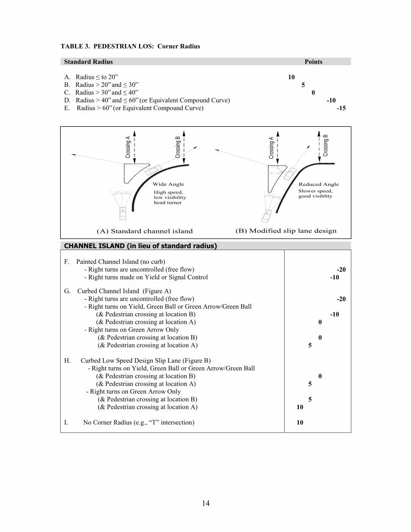
14
TABLE 3. PEDESTRIAN LOS: Corner Radius
Standard Radius Points A. Radius ≤ to 20‟ B. Radius > 20‟ and ≤ 30‟ C. Radius > 30‟ and ≤ 40‟ D. Radius > 40‟ and ≤ 60‟ (or Equivalent Compound Curve) E. Radius > 60‟ (or Equivalent Compound Curve)
10 5 0 -10 -15
CHANNEL ISLAND (in lieu of standard radius) F. Painted Channel Island (no curb) - Right turns are uncontrolled (free flow) - Right turns made on Yield or Signal Control G. Curbed Channel Island (Figure A) - Right turns are uncontrolled (free flow) - Right turns on Yield, Green Ball or Green Arrow/Green Ball (& Pedestrian crossing at location B) (& Pedestrian crossing at location A) - Right turns on Green Arrow Only (& Pedestrian crossing at location B) (& Pedestrian crossing at location A) H. Curbed Low Speed Design Slip Lane (Figure B) - Right turns on Yield, Green Ball or Green Arrow/Green Ball (& Pedestrian crossing at location B) (& Pedestrian crossing at location A) - Right turns on Green Arrow Only (& Pedestrian crossing at location B) (& Pedestrian crossing at location A) I. No Corner Radius (e.g., “T” intersection)
-20 -10 -20 -10 0 0 5 0 5 5 10 10
Wide Angle Reduced Angle
High speed, low visibility head turner
Slower speed, good visiblity
(A) Standard channel island (B) Modified slip lane design
Cro
ssin
g A
Cro
ssin
g B
Cro
ssin
g B
Cro
ssin
g A
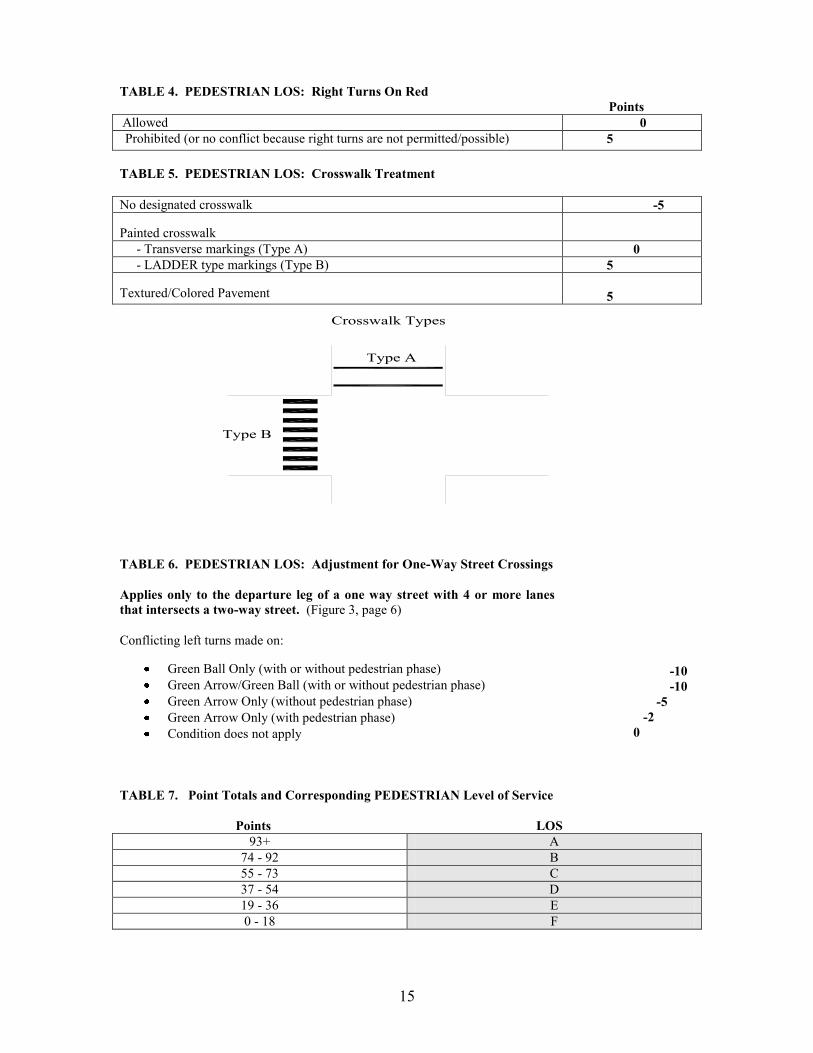
15
TABLE 4. PEDESTRIAN LOS: Right Turns On Red Points Allowed 0 Prohibited (or no conflict because right turns are not permitted/possible) 5 TABLE 5. PEDESTRIAN LOS: Crosswalk Treatment No designated crosswalk -5 Painted crosswalk
- Transverse markings (Type A) 0 - LADDER type markings (Type B) 5 Textured/Colored Pavement
5
Type A
Type B
Crosswalk Types
TABLE 6. PEDESTRIAN LOS: Adjustment for One-Way Street Crossings Applies only to the departure leg of a one way street with 4 or more lanes that intersects a two-way street. (Figure 3, page 6) Conflicting left turns made on:
Green Ball Only (with or without pedestrian phase) Green Arrow/Green Ball (with or without pedestrian phase) Green Arrow Only (without pedestrian phase) Green Arrow Only (with pedestrian phase) Condition does not apply
-10 -10 -5 -2 0
TABLE 7. Point Totals and Corresponding PEDESTRIAN Level of Service
Points LOS 93+ A
74 - 92 B 55 - 73 C 37 - 54 D 19 - 36 E 0 - 18 F

16
BICYCLE LEVEL OF SERVICE CALCULATION TABLE 8. BICYCLE LOS: Bicycle Travel Way & Speed of Adjacent Traffic
Departure Leg
BIK
E
Approach Leg Bike Travels in: (Approach/Departure Legs) Speed Limit Points Shared Auto Lane to
Shared Auto Lane (lanes ≤ 12‟ wide) ≥ 40 mph 5 30 to 35 mph 30 ‹ 30 mph 50 Shared Auto Lane to
Wide Curb Lane (13‟ to 14‟ wide) ≥ 40 mph 20 30 to 35 mph 40 ‹ 30 mph 55 Shared Auto Lane to
Bike Lane ≥ 40 mph 35 30 to 35 mph 50 ‹ 30 mph 60 Shared Wide Curb Lane
To Shared Auto Lane ≥ 40 mph 15 30 to 35 mph 35 ‹ 30 mph 50 Shared Wide Curb Lane to
Wide Curb Lane (13‟ to 14‟ wide) ≥ 40 mph 30 30 to 35 mph 50 ‹ 30 mph 60 Shared Wide Curb Lane to
Bike Lane ≥ 40 mph 45 30 to 35 mph 60 ‹ 30 mph 70

17
TABLE 8 (continued) Bike Travels in: (Approach/Departure Legs) Speed Limit Points Bike Lane to
Shared Auto Lane (lanes ≤ 12‟ wide) ≥ 40 mph 30 30 to 35 mph 45 ‹ 30 mph 55 Bike Lane to
Wide Curb Lane (13‟ to 14‟ wide) ≥ 40 mph 40 30 to 35 mph 55 ‹ 30 mph 65 Bike Lane to
Bike Lane ≥ 40 mph 60 30 to 35 mph 70 ‹ 30 mph 80 TABLE 9. BICYCLE LOS: Signal Features – Left Turn Phasing & Stop Bar Location Vehicular Left Turn Phase – turns opposing cyclists (Figure 4, page 7)
Points
Made on Green Ball Only 0 Made on Green Ball/Green Arrow 5 Made on Green Arrow Only 15 No Left Turn Conflict (e.g., “T” intersection, one-way streets) 15 Stop Bar Location
Shared stop bar - automobiles & bikes stop at common point 0 Advanced stop bar – bikes stop closer to intersection than automobiles 10
LeftTurnConflict
Rt. Turn on RedConflict
Right Turn Conflict
Bicycle Crossing Conflicts
BIKE
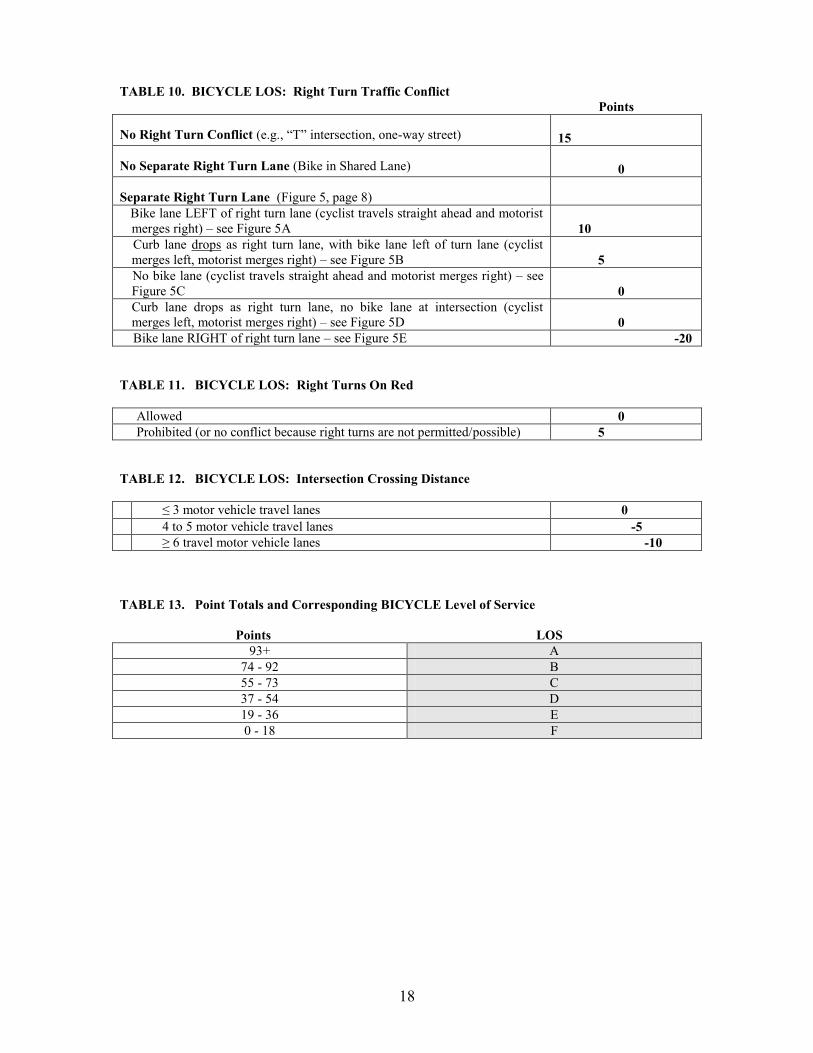
18
TABLE 10. BICYCLE LOS: Right Turn Traffic Conflict Points No Right Turn Conflict (e.g., “T” intersection, one-way street)
15
No Separate Right Turn Lane (Bike in Shared Lane)
0
Separate Right Turn Lane (Figure 5, page 8)
Bike lane LEFT of right turn lane (cyclist travels straight ahead and motorist merges right) – see Figure 5A
10
Curb lane drops as right turn lane, with bike lane left of turn lane (cyclist merges left, motorist merges right) – see Figure 5B
5
No bike lane (cyclist travels straight ahead and motorist merges right) – see Figure 5C
0
Curb lane drops as right turn lane, no bike lane at intersection (cyclist merges left, motorist merges right) – see Figure 5D
0
Bike lane RIGHT of right turn lane – see Figure 5E -20 TABLE 11. BICYCLE LOS: Right Turns On Red Allowed 0 Prohibited (or no conflict because right turns are not permitted/possible) 5 TABLE 12. BICYCLE LOS: Intersection Crossing Distance ≤ 3 motor vehicle travel lanes 0 4 to 5 motor vehicle travel lanes -5 ≥ 6 travel motor vehicle lanes -10 TABLE 13. Point Totals and Corresponding BICYCLE Level of Service
Points LOS 93+ A
74 - 92 B 55 - 73 C 37 - 54 D 19 - 36 E 0 - 18 F

19
Intersection Example # 1 Application of the pedestrian and bicycle level of service methodologies for an example intersection is presented in Figures 6 and 7. The intersection evaluated is that of a one-way street (4th Street) and a two-way street (McDowell Street) in downtown Charlotte. The sample worksheets in figures 6 and 7 provide information on features relevant to the intersection.
B IKE LANE
20 'R
20 'R
15 'R
25 'R
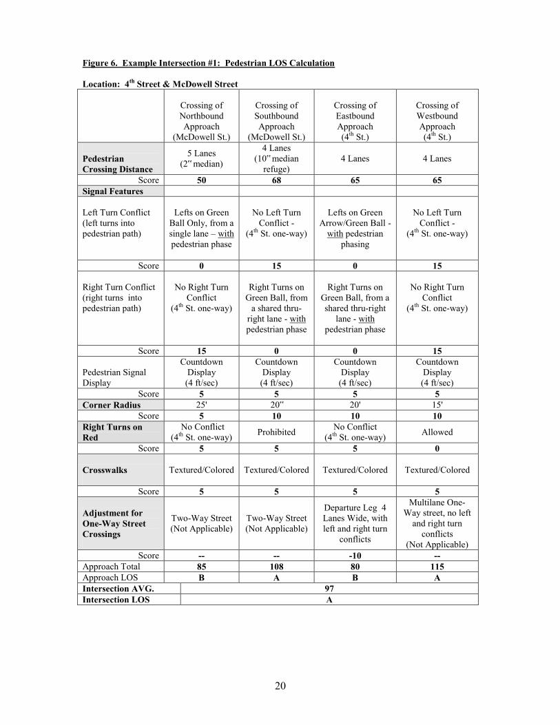
20
Figure 6. Example Intersection #1: Pedestrian LOS Calculation
Location: 4th Street & McDowell Street
Crossing of Northbound Approach
(McDowell St.)
Crossing of Southbound Approach
(McDowell St.)
Crossing of Eastbound Approach (4th St.)
Crossing of Westbound Approach (4th St.)
Pedestrian Crossing Distance
5 Lanes (2‟ median)
4 Lanes (10‟ median
refuge)
4 Lanes
4 Lanes
Score 50 68 65 65
Signal Features
Left Turn Conflict (left turns into pedestrian path)
Lefts on Green
Ball Only, from a single lane – with pedestrian phase
No Left Turn Conflict -
(4th St. one-way)
Lefts on Green
Arrow/Green Ball - with pedestrian
phasing
No Left Turn Conflict -
(4th St. one-way)
Score 0 15 0 15
Right Turn Conflict (right turns into pedestrian path)
No Right Turn Conflict
(4th St. one-way)
Right Turns on
Green Ball, from a shared thru-
right lane - with pedestrian phase
Right Turns on
Green Ball, from a shared thru-right
lane - with pedestrian phase
No Right Turn Conflict
(4th St. one-way)
Score 15 0 0 15
Pedestrian Signal Display
Countdown Display (4 ft/sec)
Countdown Display (4 ft/sec)
Countdown Display (4 ft/sec)
Countdown Display (4 ft/sec)
Score 5 5 5 5 Corner Radius 25' 20‟ 20' 15'
Score 5 10 10 10 Right Turns on Red
No Conflict (4th St. one-way) Prohibited No Conflict
(4th St. one-way) Allowed
Score 5 5 5 0
Crosswalks
Textured/Colored
Textured/Colored
Textured/Colored
Textured/Colored
Score 5 5 5 5
Adjustment for One-Way Street Crossings
Two-Way Street (Not Applicable)
Two-Way Street (Not Applicable)
Departure Leg 4 Lanes Wide, with left and right turn
conflicts
Multilane One-Way street, no left
and right turn conflicts
(Not Applicable) Score -- -- -10 --
Approach Total 85 108 80 115 Approach LOS B A B A Intersection AVG. 97 Intersection LOS A
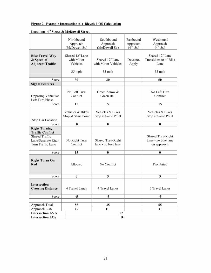
21
Figure 7. Example Intersection #1: Bicycle LOS Calculation
Location: 4th Street & McDowell Street
Northbound Approach
(McDowell St.)
Southbound
Approach (McDowell St.)
Eastbound Approach (4th St.)
Westbound Approach (4th St.)
Bike Travel Way & Speed of Adjacent Traffic
Shared 12‟ Lane
with Motor Vehicles
35 mph
Shared 12‟ Lane
with Motor Vehicles
35 mph
Does not Apply
Shared 12‟ Lane
Transitions to 4‟ Bike Lane
35 mph
Score 30 30 50
Signal Features
Opposing Vehicular Left Turn Phase
No Left Turn
Conflict
Green Arrow & Green Ball
No Left Turn Conflict
Score 15 5 15
Stop Bar Location
Vehicles & Bikes Stop at Same Point
Vehicles & Bikes
Stop at Same Point
Vehicles & Bikes Stop at Same Point
Score 0 0 0 Right Turning Traffic Conflict
No Right Turn
Conflict
Shared Thru-Right lane - no bike lane
Shared Thru-Right Lane - no bike lane
on approach
Shared Traffic Lane/Separate Right Turn Traffic Lane
Score 15 0 0
Right Turns On Red
Allowed
No Conflict
Prohibited
Score 0 5 5 Intersection Crossing Distance
4 Travel Lanes
4 Travel Lanes
5 Travel Lanes
Score -5 -5 -5
Approach Total 55 35 65 Approach LOS C- E+ C Intersection AVG. 52 Intersection LOS D+
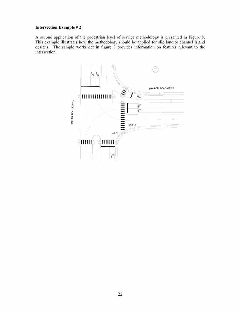
22
Intersection Example # 2 A second application of the pedestrian level of service methodology is presented in Figure 8. This example illustrates how the methodology should be applied for slip lane or channel island designs. The sample worksheet in figure 8 provides information on features relevant to the intersection.
SHARON ROAD WEST
SO
UT
H B
OU
LE
VA
RD
40' R
150' R
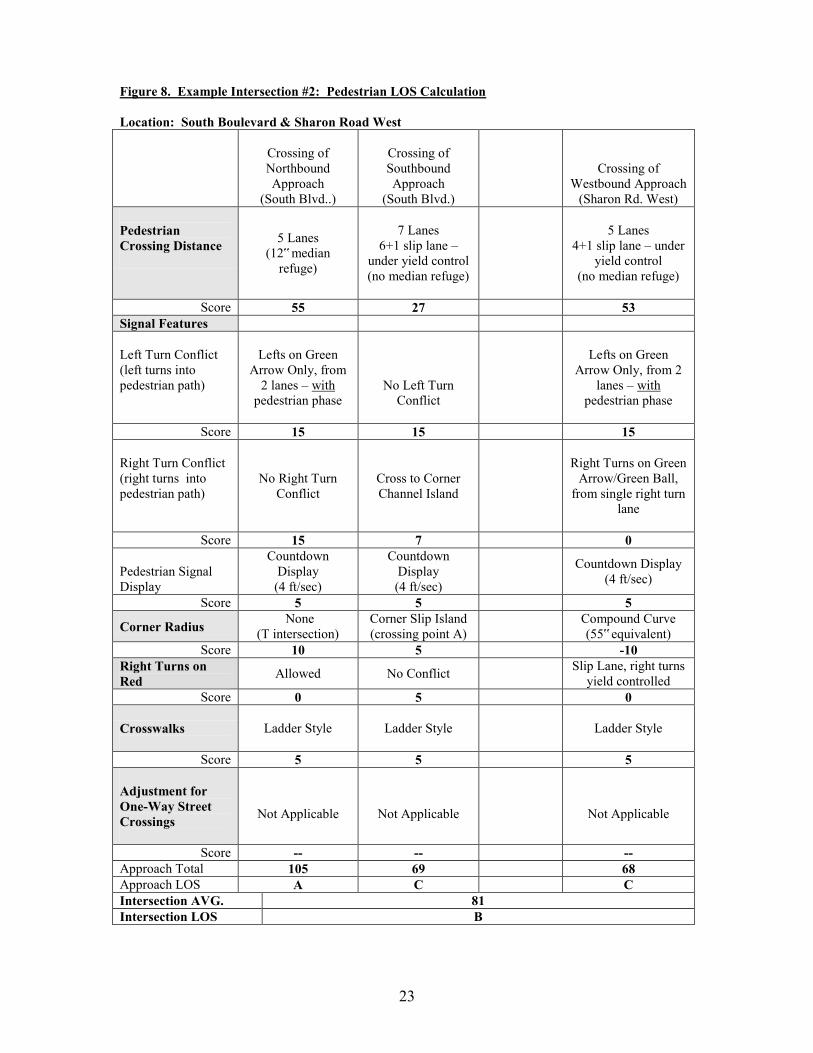
23
Figure 8. Example Intersection #2: Pedestrian LOS Calculation
Location: South Boulevard & Sharon Road West
Crossing of Northbound Approach
(South Blvd..)
Crossing of Southbound Approach
(South Blvd.)
Crossing of Westbound Approach
(Sharon Rd. West) Pedestrian Crossing Distance
5 Lanes
(12‟ median refuge)
7 Lanes
6+1 slip lane – under yield control (no median refuge)
5 Lanes
4+1 slip lane – under yield control
(no median refuge)
Score 55 27 53 Signal Features
Left Turn Conflict (left turns into pedestrian path)
Lefts on Green
Arrow Only, from 2 lanes – with
pedestrian phase
No Left Turn Conflict
Lefts on Green Arrow Only, from 2
lanes – with pedestrian phase
Score 15 15 15
Right Turn Conflict (right turns into pedestrian path)
No Right Turn Conflict
Cross to Corner Channel Island
Right Turns on Green
Arrow/Green Ball, from single right turn
lane
Score 15 7 0
Pedestrian Signal Display
Countdown Display (4 ft/sec)
Countdown Display (4 ft/sec)
Countdown Display (4 ft/sec)
Score 5 5 5
Corner Radius None (T intersection)
Corner Slip Island (crossing point A) Compound Curve
(55‟ equivalent) Score 10 5 -10
Right Turns on Red Allowed No Conflict Slip Lane, right turns
yield controlled Score 0 5 0
Crosswalks
Ladder Style
Ladder Style
Ladder Style
Score 5 5 5
Adjustment for One-Way Street Crossings
Not Applicable
Not Applicable
Not Applicable
Score -- -- -- Approach Total 105 69 68 Approach LOS A C C Intersection AVG. 81 Intersection LOS B

Appendix C
Guidelines for Designing Curb Return Radii

July, 2007
1
Appendix C: Curb Return Radii Design Guidelines I. Overview and Purpose The intent of the curb return radii design guidelines is to establish a procedure that allows flexibility in designing curb radii to reflect conditions of specific locations, while assuring that the result will yield the smallest radii that are feasible to accommodate the specified design vehicle. The primary reason for minimizing curb radii is to help provide shorter crossings for pedestrians. In general, the distance a pedestrian must cross to reach the opposite curb will decrease as the curb radius decreases. Similarly, the larger the radius, the greater the distance the pedestrian has to traverse and the more the pedestrian is potentially out of the line-of-sight of the driver. Smaller radii can also serve as a traffic calming design feature, requiring vehicles to turn at slower speeds, depending on the width of the street. Smaller curb radii, therefore, serve to:
Minimize the (unprotected) distance pedestrians need to cross, Allow for better alignment of the crosswalk with the connecting sidewalks (i.e., provide a continuous path of travel), Assure adequate space at the corner for proper placement and alignment of ADA-compliant curb ramps (typically, one per each direction of travel is desired),
Moderate the speeds of turning vehicles, Improve visibility of drivers and pedestrians, Result in improved compliance with “No Turn On Red” regulations.
While the overall intent is to keep radii small and improve pedestrian crossings, curb radii will be designed to accommodate the expected type and volume of vehicle turning at the intersection. Properly designed curb radii will provide sufficient space for the expected vehicles to maneuver through their turns safely, while minimizing conflicts between cars, trucks, buses, bicyclists and pedestrians. The design should also take into account the typology of the two intersecting streets, the level of pedestrian activity expected, the location of crosswalks, curb ramps, presence or absence of bike lanes, pedestrian refuge islands, curb extensions, bus stops and on-street parking, and whether the intersection is signalized or unsignalized. II. Design Criteria The following guidelines are to be used to determine the curb radii at any given intersection. For the purposes of this process, the AASHTO Green Book‟s “crawl speeds” are assumed for the turning speeds of vehicles.
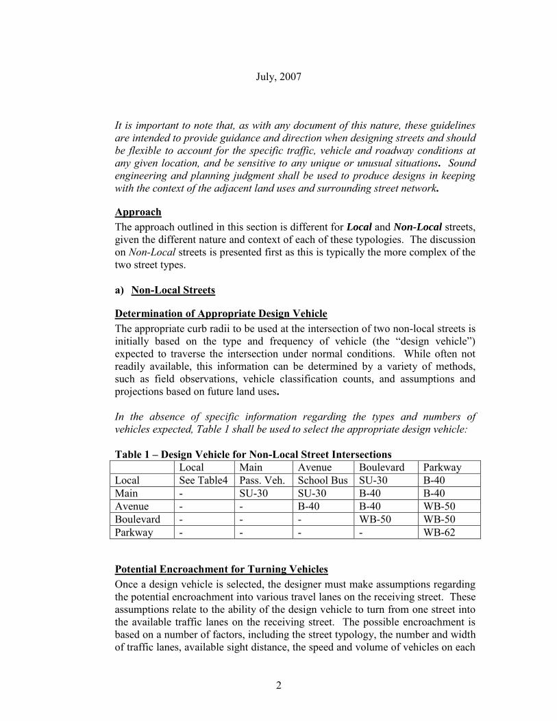
July, 2007
2
It is important to note that, as with any document of this nature, these guidelines are intended to provide guidance and direction when designing streets and should be flexible to account for the specific traffic, vehicle and roadway conditions at any given location, and be sensitive to any unique or unusual situations. Sound engineering and planning judgment shall be used to produce designs in keeping with the context of the adjacent land uses and surrounding street network.
Approach The approach outlined in this section is different for Local and Non-Local streets, given the different nature and context of each of these typologies. The discussion on Non-Local streets is presented first as this is typically the more complex of the two street types. a) Non-Local Streets
Determination of Appropriate Design Vehicle The appropriate curb radii to be used at the intersection of two non-local streets is initially based on the type and frequency of vehicle (the “design vehicle”) expected to traverse the intersection under normal conditions. While often not readily available, this information can be determined by a variety of methods, such as field observations, vehicle classification counts, and assumptions and projections based on future land uses. In the absence of specific information regarding the types and numbers of vehicles expected, Table 1 shall be used to select the appropriate design vehicle: Table 1 – Design Vehicle for Non-Local Street Intersections Local Main Avenue Boulevard Parkway Local See Table4 Pass. Veh. School Bus SU-30 B-40 Main - SU-30 SU-30 B-40 B-40 Avenue - - B-40 B-40 WB-50 Boulevard - - - WB-50 WB-50 Parkway - - - - WB-62
Potential Encroachment for Turning Vehicles Once a design vehicle is selected, the designer must make assumptions regarding the potential encroachment into various travel lanes on the receiving street. These assumptions relate to the ability of the design vehicle to turn from one street into the available traffic lanes on the receiving street. The possible encroachment is based on a number of factors, including the street typology, the number and width of traffic lanes, available sight distance, the speed and volume of vehicles on each
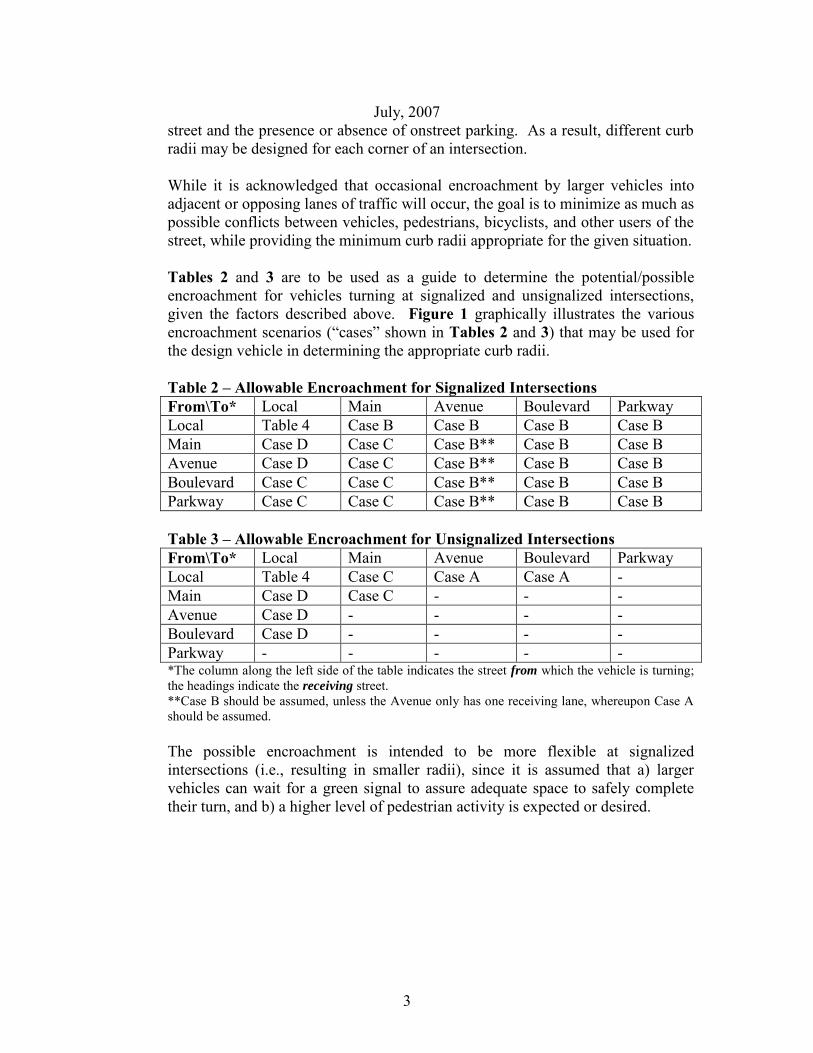
July, 2007
3
street and the presence or absence of onstreet parking. As a result, different curb radii may be designed for each corner of an intersection. While it is acknowledged that occasional encroachment by larger vehicles into adjacent or opposing lanes of traffic will occur, the goal is to minimize as much as possible conflicts between vehicles, pedestrians, bicyclists, and other users of the street, while providing the minimum curb radii appropriate for the given situation. Tables 2 and 3 are to be used as a guide to determine the potential/possible encroachment for vehicles turning at signalized and unsignalized intersections, given the factors described above. Figure 1 graphically illustrates the various encroachment scenarios (“cases” shown in Tables 2 and 3) that may be used for the design vehicle in determining the appropriate curb radii. Table 2 – Allowable Encroachment for Signalized Intersections From\To* Local Main Avenue Boulevard Parkway Local Table 4 Case B Case B Case B Case B Main Case D Case C Case B** Case B Case B Avenue Case D Case C Case B** Case B Case B Boulevard Case C Case C Case B** Case B Case B Parkway Case C Case C Case B** Case B Case B Table 3 – Allowable Encroachment for Unsignalized Intersections From\To* Local Main Avenue Boulevard Parkway Local Table 4 Case C Case A Case A - Main Case D Case C - - - Avenue Case D - - - - Boulevard Case D - - - - Parkway - - - - - *The column along the left side of the table indicates the street from which the vehicle is turning; the headings indicate the receiving street. **Case B should be assumed, unless the Avenue only has one receiving lane, whereupon Case A should be assumed.
The possible encroachment is intended to be more flexible at signalized intersections (i.e., resulting in smaller radii), since it is assumed that a) larger vehicles can wait for a green signal to assure adequate space to safely complete their turn, and b) a higher level of pedestrian activity is expected or desired.
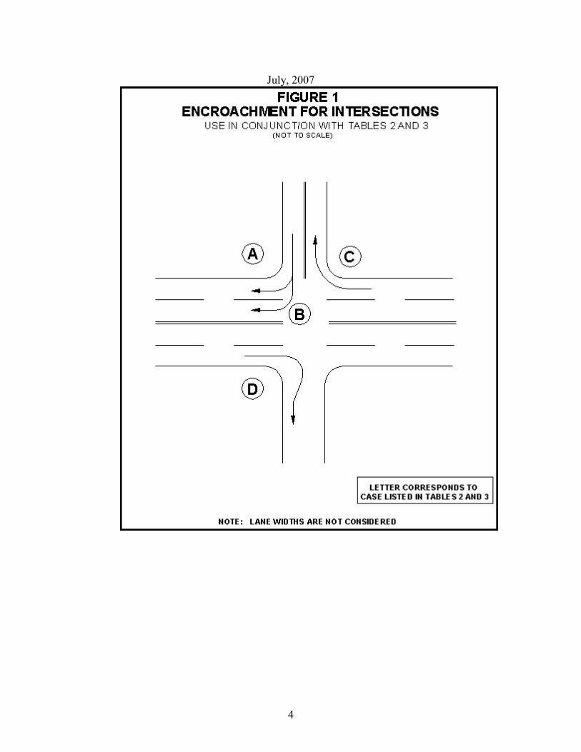
July, 2007
4
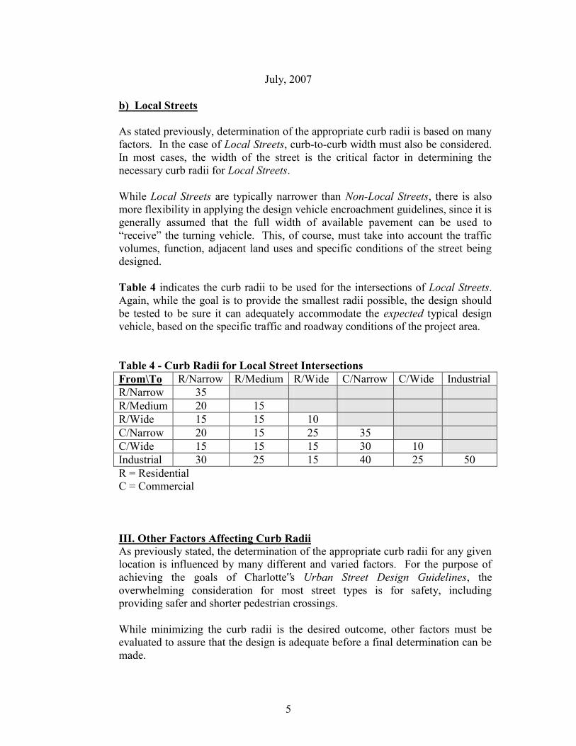
July, 2007
5
b) Local Streets As stated previously, determination of the appropriate curb radii is based on many factors. In the case of Local Streets, curb-to-curb width must also be considered. In most cases, the width of the street is the critical factor in determining the necessary curb radii for Local Streets. While Local Streets are typically narrower than Non-Local Streets, there is also more flexibility in applying the design vehicle encroachment guidelines, since it is generally assumed that the full width of available pavement can be used to “receive” the turning vehicle. This, of course, must take into account the traffic volumes, function, adjacent land uses and specific conditions of the street being designed. Table 4 indicates the curb radii to be used for the intersections of Local Streets. Again, while the goal is to provide the smallest radii possible, the design should be tested to be sure it can adequately accommodate the expected typical design vehicle, based on the specific traffic and roadway conditions of the project area. Table 4 - Curb Radii for Local Street Intersections From\To R/Narrow R/Medium R/Wide C/Narrow C/Wide Industrial R/Narrow 35 R/Medium 20 15 R/Wide 15 15 10 C/Narrow 20 15 25 35 C/Wide 15 15 15 30 10 Industrial 30 25 15 40 25 50 R = Residential C = Commercial
III. Other Factors Affecting Curb Radii As previously stated, the determination of the appropriate curb radii for any given location is influenced by many different and varied factors. For the purpose of achieving the goals of Charlotte‟s Urban Street Design Guidelines, the overwhelming consideration for most street types is for safety, including providing safer and shorter pedestrian crossings. While minimizing the curb radii is the desired outcome, other factors must be evaluated to assure that the design is adequate before a final determination can be made.
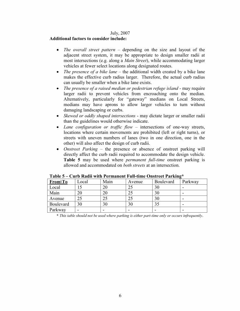
July, 2007
6
Additional factors to consider include:
The overall street pattern – depending on the size and layout of the adjacent street system, it may be appropriate to design smaller radii at most intersections (e.g. along a Main Street), while accommodating larger vehicles at fewer select locations along designated routes.
The presence of a bike lane – the additional width created by a bike lane makes the effective curb radius larger. Therefore, the actual curb radius can usually be smaller when a bike lane exists.
The presence of a raised median or pedestrian refuge island - may require larger radii to prevent vehicles from encroaching onto the median. Alternatively, particularly for “gateway” medians on Local Streets, medians may have aprons to allow larger vehicles to turn without damaging landscaping or curbs.
Skewed or oddly shaped intersections - may dictate larger or smaller radii than the guidelines would otherwise indicate.
Lane configuration or traffic flow – intersections of one-way streets, locations where certain movements are prohibited (left or right turns), or streets with uneven numbers of lanes (two in one direction, one in the other) will also affect the design of curb radii.
Onstreet Parking – the presence or absence of onstreet parking will directly affect the curb radii required to accommodate the design vehicle. Table 5 may be used where permanent full-time onstreet parking is allowed and accommodated on both streets at an intersection.
Table 5 – Curb Radii with Permanent Full-time Onstreet Parking* From\To Local Main Avenue Boulevard Parkway Local 15 20 25 30 - Main 20 20 25 30 - Avenue 25 25 25 30 - Boulevard 30 30 30 35 - Parkway - - - - -
* This table should not be used where parking is either part-time only or occurs infrequently.