Embed Size (px)
Citation preview
us. precision lenslncormmled
CRT PROJECTION OPTICS
Jacob MoskovichOPCON Associates Incorporated
Cincinnati, Ohio
James J. BohacheU.S. Precision Lens, incorporated
Cincinnati, Ohio
John D. RudolphU.S. Precision Lens, Incorporated
Cincinnati, Ohio
Seminar presented to the Society for Information Display (SID)in Anaheim, California, May 6, 1991.
SEMINAR M-7
CRT PROJECTION OPTICS
Jacob MoskovichOPCON Associates Incorporated
Cincinnati, OH
James J. BohacheU.S. Precision Lens, inc.
Cincinnati, OH
John D. RudolphU.S. Precision Lens, Inc.
Cincinnati, OH
Summary
The objective of this seminar is to provide a general background and a basicunderstanding of some of the tradeoffs involved in the specification, designand incorporation of projection optics in CRT projection systems. Broadcaststandards, the visual requirements of the image and the effect of CRT andscreen characteristics are considered. Overall system requirements specificto rear- and front-screen three-lens systems are emphasized. The evolutionof the projection lens itself is covered in detail. Manufacturability and costconsiderations are included throughout as appropriate.
ISSN0887-915X/91/-M-7-$1.00 + . O O 0 1 9 9 1 S I D
CRT PROJECTION OPTICS
Jacob MoskovichJames J. Bohache
John Rudolph
Introduction
The Tvpes of CRT Proiection Svstem
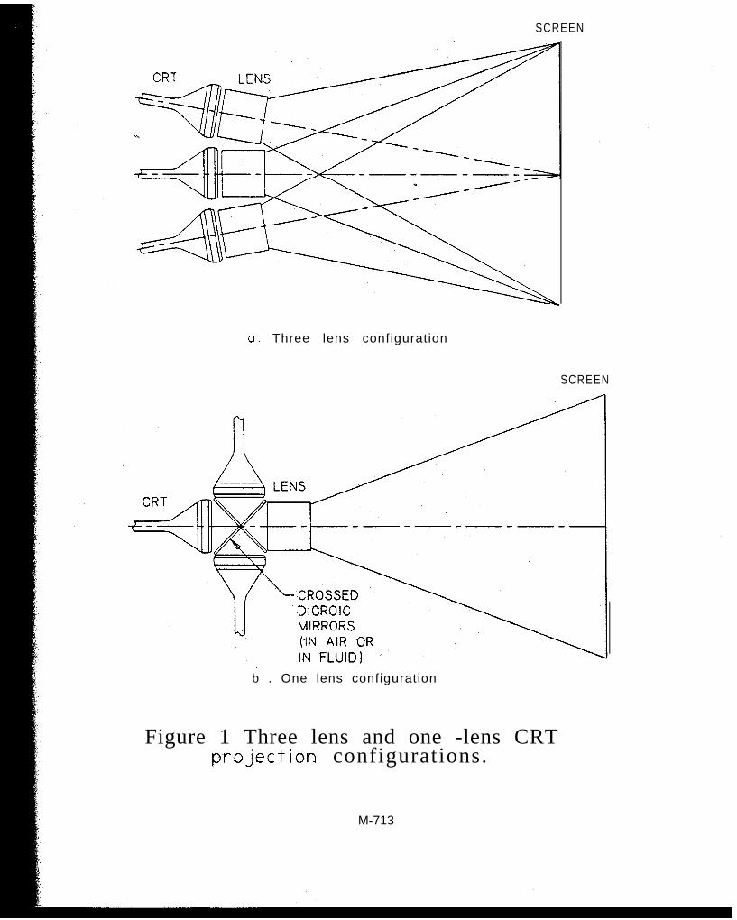
There are two basic design types for CRT projection systems, the three lens configurationand the one lens configuration (see Figure 1). In the three-lens system, the final color imageresults from the superposition of the images from three monochromatic CRT’s. In the one-lenssystem, a combination of dichroic mirrors is used to effectively superimpose the three CRTphosphors, and a single lens is then used to project this “color” phosphor onto the viewingscreen.
Although some aspects of system design are common to both of these configurations, thedifferences are significant. This presentation will deal exclusively with the three-lensconfiguration, since it is by far the most common design in both consumer and industrialprojection systems available today. It should be noted, however, that the one-lens systemconfiguration will probably be preferred for LCD projection systems in the future, and will takeon a growing importance as these systems are introduced.
The three-lens configuration is used in both front screen and rear screen applications, andthe basic optical components of both are the same (see Figure 2). A CRT produces an imageon the phosphor surface, and a projection lens is used to form a real image of the phosphor onthe surface of a screen, which directs the light to the viewer. Each of these three components,the CRT, the screen and the projection lens, will be discussed in what follows. The specialdesign considerations for rear screen versus front screen systems will also be addressed. Sincesystem cost has been and will continue to be a driving factor in the design of CRT projectionsystems, cost considerations will be considered throughout the presentation where appropriate.
Broadcast Standards for Proiection Svstems ’
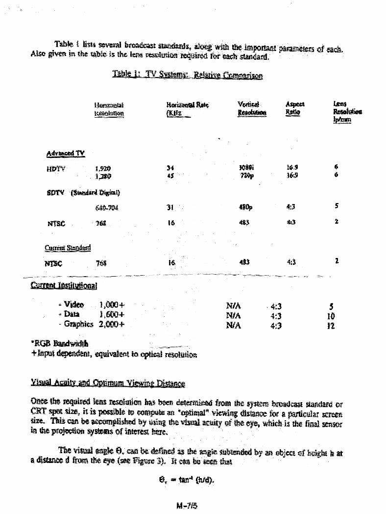
Broadcast standards are an important consideration in the design of CRT projectionsystems because they, along with the minimum CRT spot size, determine the resolutionrequirements for the projection lens. It is not within the scope of this presentation to deal withthe pros and cons of the different standards which have been suggested for HDTV or the many“step-up” systems. It is sufficient for our purposes to state that the number of lines per scan,the scan rate, the phosphor size and the broadcast bandwidth for a particular standard willdetermine the smallest resolution element on the phosphor. It will be assumed that the CRT spotsize is sufficiently small to allow detail of the size of this resolution element to be resolved;otherwise, the CRT spot size itself will set the smallest CRT resolution element size.
M-712
SCREEN
a. Three lens configuration
SCREEN
b . One lens configuration
Figure 1 Three lens and one -lens CRTp-rejection configurations.
M-713
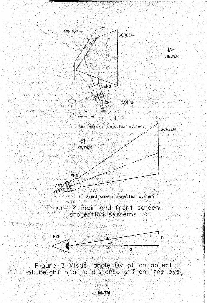
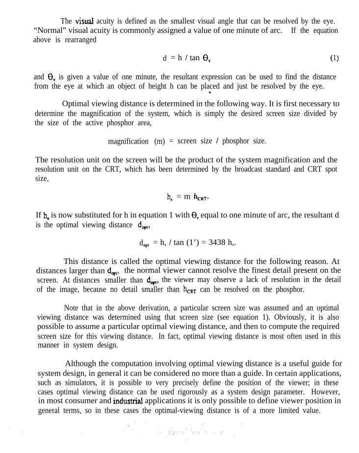
The visual acuity is defined as the smallest visual angle that can be resolved by the eye.“Normal” visual acuity is commonly assigned a value of one minute of arc. If the equationabove is rearranged
d = h / tan 8, (1)
and 8, is given a value of one minute, the resultant expression can be used to find the distancefrom the eye at which an object of height h can be placed and just be resolved by the eye.w
Optimal viewing distance is determined in the following way. It is first necessary todetermine the magnification of the system, which is simply the desired screen size divided bythe size of the active phosphor area,
magnification (m) = screen size / phosphor size.
The resolution unit on the screen will be the product of the system magnification and theresolution unit on the CRT, which has been determined by the broadcast standard and CRT spotsize,
hs = m h,,,.
If h, is now substituted for h in equation 1 with 6, equal to one minute of arc, the resultant dis the optimal viewing distance dqt,
dopt = h, / tan (1’) = 3438 h,.
This distance is called the optimal viewing distance for the following reason. Atdistances larger than dopl, the normal viewer cannot resolve the finest detail present on thescreen. At distances smaller than dop,, the viewer may observe a lack of resolution in the detailof the image, because no detail smaller than hcRT can be resolved on the phosphor.
Note that in the above derivation, a particular screen size was assumed and an optimalviewing distance was determined using that screen size (see equation 1). Obviously, it is alsopossible to assume a particular optimal viewing distance, and then to compute the requiredscreen size for this viewing distance. In fact, optimal viewing distance is most often used in thismanner in system design.
Although the computation involving optimal viewing distance is a useful guide forsystem design, in general it can be considered no more than a guide. In certain applications,such as simulators, it is possible to very precisely define the position of the viewer; in thesecases optimal viewing distance can be used rigorously as a system design parameter. However,in most consumer and industrial applications it is only possible to define viewer position ingeneral terms, so in these cases the optimal-viewing distance is of a more limited value.
The CRT
In any optical system, the quality of the image can be no better than the quality of theobject. In the case of conventional projection TV, the CRT source dictates the starting pointfrom which the optical system begins its critical function.
Construction
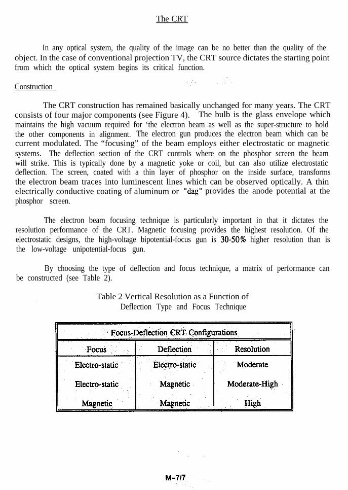
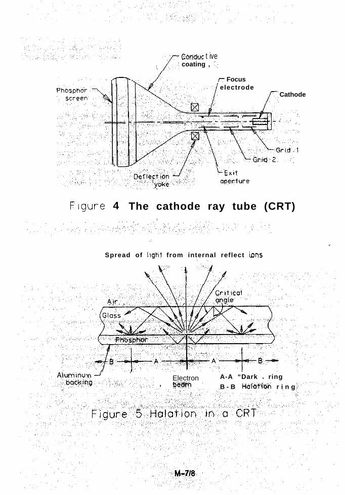
The CRT construction has remained basically unchanged for many years. The CRTconsists of four major components (see Figure 4). The bulb is the glass envelope whichmaintains the high vacuum required for ‘the electron beam as well as the super-structure to holdthe other components in alignment. The electron gun produces the electron beam which can becurrent modulated. The “focusing” of the beam employs either electrostatic or magneticsystems. The deflection section of the CRT controls where on the phosphor screen the beamwill strike. This is typically done by a magnetic yoke or coil, but can also utilize electrostaticdeflection. The screen, coated with a thin layer of phosphor on the inside surface, transformsthe electron beam traces into luminescent lines which can be observed optically. A thinelectrically conductive coating of aluminum or “dag” provides the anode potential at thephosphor screen.
The electron beam focusing technique is particularly important in that it dictates theresolution performance of the CRT. Magnetic focusing provides the highest resolution. Of theelectrostatic designs, the high-voltage bipotential-focus gun is 30-50% higher resolution than isthe low-voltage unipotential-focus gun.
By choosing the type of deflection and focus technique, a matrix of performance canbe constructed (see Table 2).
Table 2 Vertical Resolution as a Function ofDeflection Type and Focus Technique
‘- fCOrid~C t ive
> coating , ‘.
/ r Focuselectrode
I
Cathode
ILExit
apef7ture
The cathode ray tube (CRT) ’Figure 4:
,1,
<
aht from internal reflect tins
a” ‘4-1,
Spread of Ii!
vi T /r”
-n-JI
Electron A-A “Dark l ring, @&m ’ B - B l-tal&fi~in r i n g
Contrast
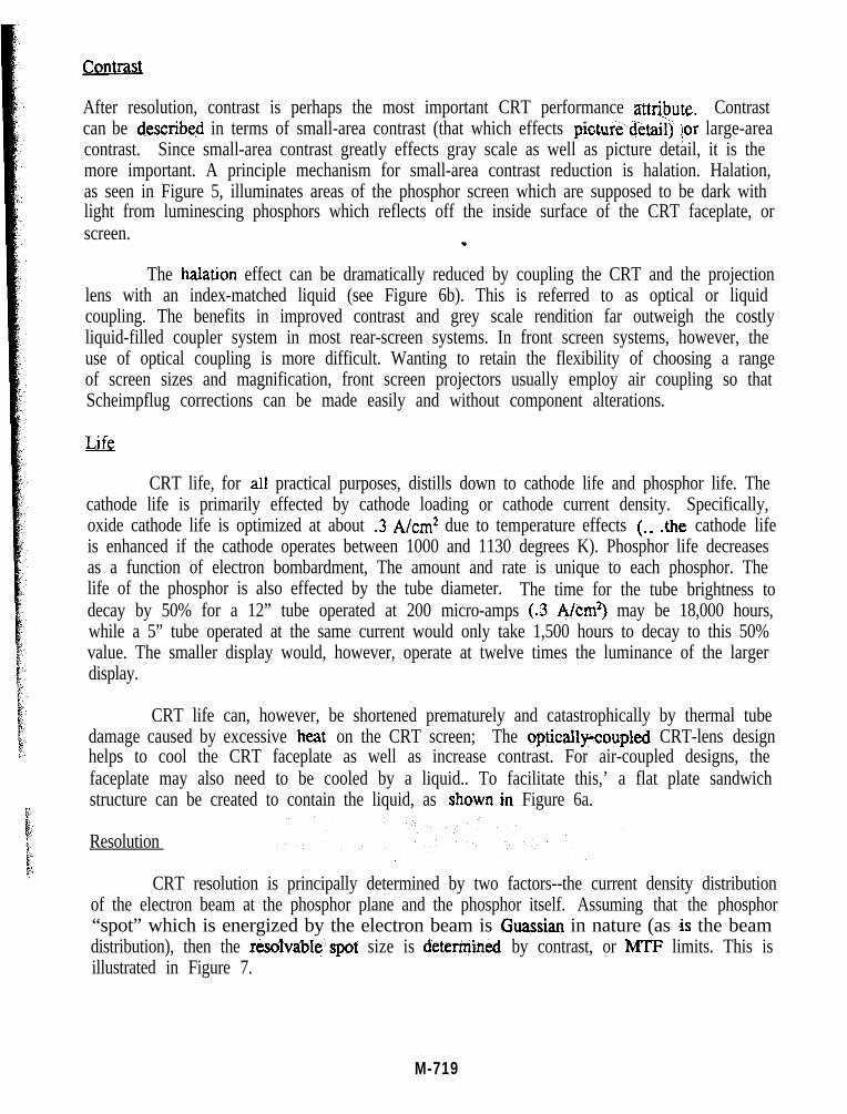
After resolution, contrast is perhaps the most important CRT performance attr$mte. Contrastcan be describe$ in terms of small-area contrast (that which effects pictui&d&tail) ior large-areacontrast. Since small-area contrast greatly effects gray scale as well as picture detail, it is themore important. A principle mechanism for small-area contrast reduction is halation. Halation,as seen in Figure 5, illuminates areas of the phosphor screen which are supposed to be dark withlight from luminescing phosphors which reflects off the inside surface of the CRT faceplate, orscreen.
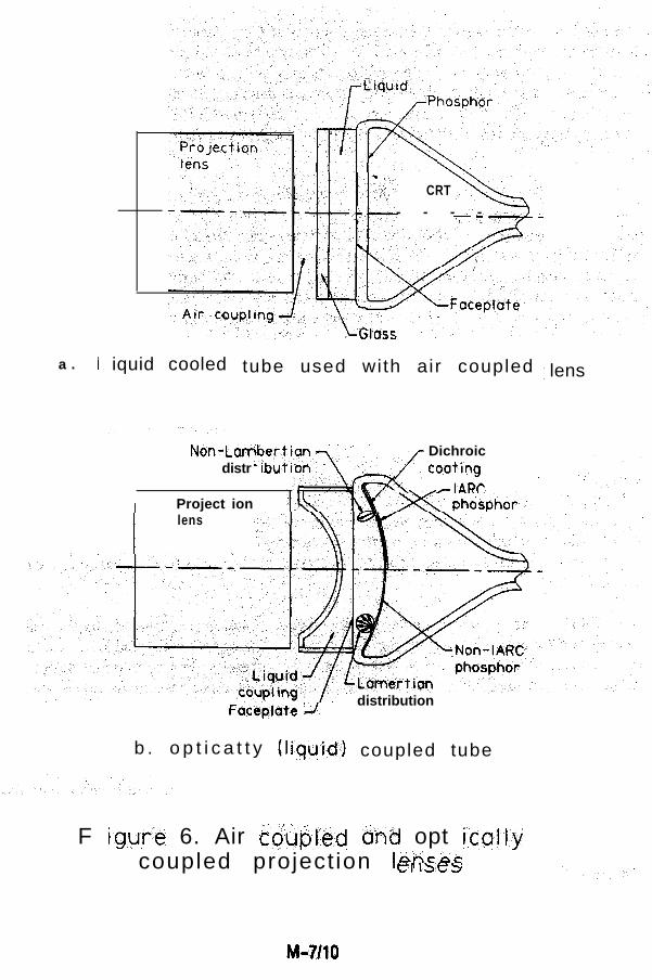
The halation effect can be dramatically reduced by coupling the CRT and the projectionlens with an index-matched liquid (see Figure 6b). This is referred to as optical or liquidcoupling. The benefits in improved contrast and grey scale rendition far outweigh the costlyliquid-filled coupler system in most rear-screen systems. In front screen systems, however, theuse of optical coupling is more difficult. Wanting to retain the flexibility of choosing a rangeof screen sizes and magnification, front screen projectors usually employ air coupling so thatScheimpflug corrections can be made easily and without component alterations.
Life
CRT life, for all practical purposes, distills down to cathode life and phosphor life. Thecathode life is primarily effected by cathode loading or cathode current density. Specifically,oxide cathode life is optimized at about .3 A/cm2 due to temperature effects (.. .the cathode lifeis enhanced if the cathode operates between 1000 and 1130 degrees K). Phosphor life decreasesas a function of electron bombardment, The amount and rate is unique to each phosphor. Thelife of the phosphor is also effected by the tube diameter. The time for the tube brightness todecay by 50% for a 12” tube operated at 200 micro-amps (.3 A/cm*) may be 18,000 hours,while a 5” tube operated at the same current would only take 1,500 hours to decay to this 50%value. The smaller display would, however, operate at twelve times the luminance of the largerdisplay.
CRT life can, however, be shortened prematurely and catastrophically by thermal tubedamage caused by excessive heat. on the CRT screen; The optically-coupM CRT-lens designhelps to cool the CRT faceplate as well as increase contrast. For air-coupled designs, thefaceplate may also need to be cooled by a liquid.. To facilitate this,’ a flat plate sandwichstructure can be created to contain the liquid, as shown.in Figure 6a.
Resolution
CRT resolution is principally determined by two factors--the current density distributionof the electron beam at the phosphor plane and the phosphor itself. Assuming that the phosphor“spot” which is energized by the electron beam is Guassian in nature (as ,is the beamdistribution), then the resolvable,spot size is determin&. by contrast, or MTF limits. This isillustrated in Figure 7.
M-719
CRT
>-
- - - - - ,
a . I iquid cooled tube used with air coupled lens
Non-Lawdistr
I Project ion
/
Dichroictooting
\ -IARC ’
Ilens
Facepla
b . o p t i c a t t y (I
te -J.distribution
iquid) coupled tube
F igwre 6. Air b&jled bnd opt icaltycoupled project ion I-----Cl 1bc.S
M-?/Xl
If the objective is 50% MTF, and if the ratio of the width to the peak separation isapproximately 0.7 at 50% modulation, then for a .l mm spot (about the best currently achievedin projection CRT’s) the peak separation could be .14 mm. For a CRT of 80 mm height (5.25”diagonal), this would yield 80 mm/.14 mm peak separation, or 570 cycles (1140 TV lines)resolution. This would be very adequate for HDTV and various data and graphics modes.However, as the beam moves off-axis, the spot quality degrades significantly. The relationshipbetween spot size and TV resolution is shown in Figure 8.
Color CRT
The color produced by the CRT is obviously a function of the phosphor chosen.Unfortunately, the phosphors are not monochromatic. In order to improve calorimetry, variouscoatings and filters are employed to reflect or absorb light of unwanted wavelengths. Arepresentative sampling of red, green, and blue CRT spectral emission plots are shown inFigures 10-12.
Curved Phosnhor
Most CRT’s used in projection TV today have flat screens or faceplates. The advantageof flat faceplates over curved-input faceplates include simplified mechanical tolerancing andreduced componentry for convergence. The single most important advantage of curved faceplateCRT’s is the increased comer illumination. This stems from the Lambertian nature of the lightemanating from the phosphor surface. A dichroic coating can be designed to reflect back lightof unwanted wavelengths, but more importantly, it can narrow the light distribution (vs. .lambertian) to help place light into the pupil of the lens. While overall brightness can beimproved as much as 40%, the comer illumination can be increased even more. This lastcombination of curved input faceplate with dichroic coatings is referred to as the “IARC” tube(see Figure 6b).
CRT’s for projection TV are available in three principle raster (useable phosphor)diagonals: the 5”, 5.75” and the 7”. The corresponding tubes are referred to as 7”) 8” and 9”)respectively.
The Screen
Projection TV screens can be categorized simply into two types, front-screen and rear-‘k&en. In both cases, various features and techniques are used to enable the viewer toex@kknce the best projected image possible.
M-711 1
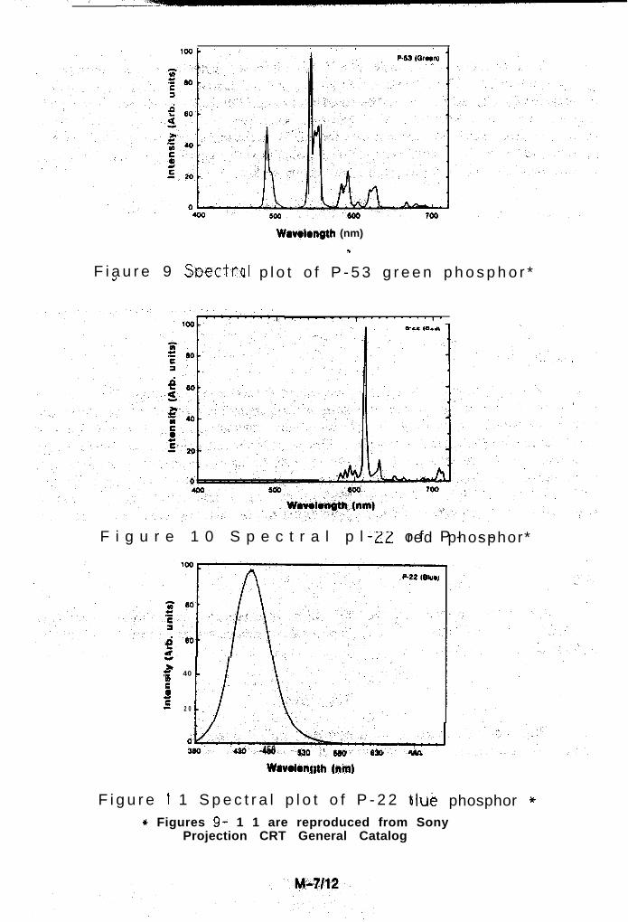
500
Wowlength (nm)*
F i a u r e 9 StsectrcJ II p l o t o f P - 5 3 g r e e n p h o s p h o r *
,......-.,.........,., e .. ,__a.
i*
.= 40tQ)
z 2 0ii
F i g u r e 1 0 S p e c t r a l p l o t o f P - - --ZZ red phosphor*
,vL430 -450 sw~‘55o 620
Wavolonf #th (nm)
rlue phosphor *F i g u r e 1 1 S p e c t r a l p l o t o f P - 2 2 t* Figures 9- 1 1 are reproduced from Sony
Projection CRT General Catalog
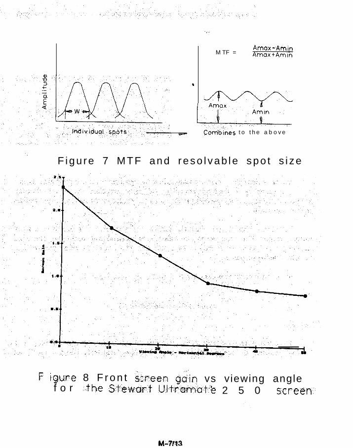
M T F =Amax-AininAmax+Amin
*
1- Comb-ynes to the above
F igu re 7 MTF and reso l vab le spo t s i ze
F lgure 8 F r o n t I&xeen gain vs viewing anglef o r -the St-ew-ar,t Ult-ramatt2 2 5 0 screen--
Front Screen
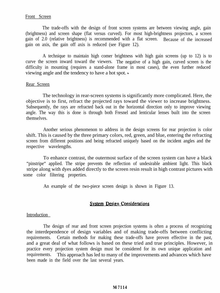
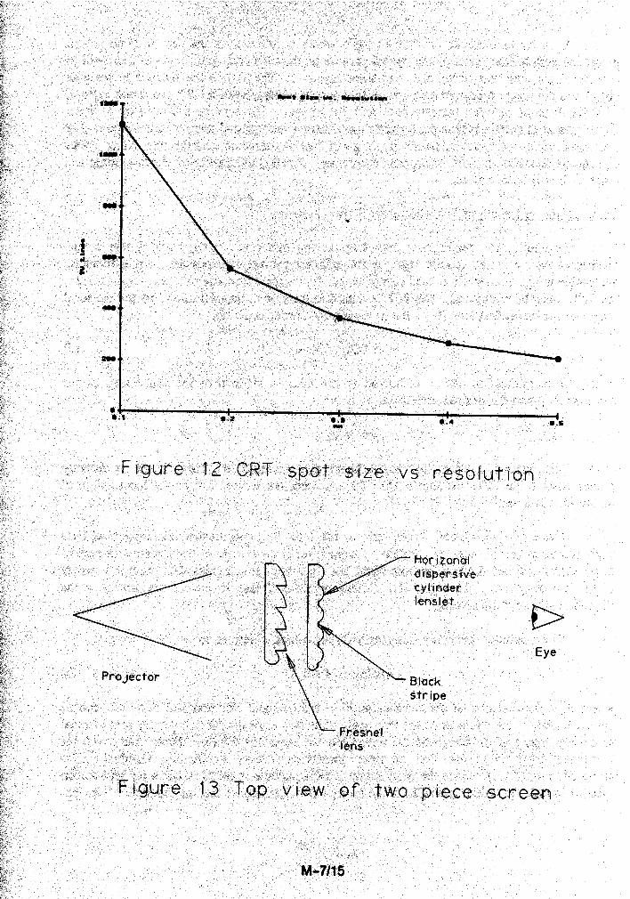
The trade-offs with the design of front screen systems are between viewing angle, gain(brightness) and screen shape (flat versus curved). For most high-brightness projectors, a screengain of 2.0 (relative brightness) is recommended with a flat screen. Because of the increasedgain on axis, the gain off axis is reduced (see Figure 12).
A technique to maintain high comer brightness with high gain screens (up to 12) is tocurve the screen inward toward the viewers. The negative of a high gain, curved screen is thedifficulty in mounting (requires a stand-alone frame in most cases), the even further reducedviewing angle and the tendency to have a hot spot. *
Rear Screen
The technology in rear-screen systems is significantly more complicated. Here, theobjective is to first, refract the projected rays toward the viewer to increase brightness.Subsequently, the rays are refracted back out in the horizontal direction only to improve viewingangle. The way this is done is through both Fresnel and lenticular lenses built into the screenthemselves.
Another serious phenomenon to address in the design screens for rear projection is colorshift. This is caused by the three primary colors, red, green, and blue, entering the refractingscreen from different positions and being refracted uniquely based on the incident angles and therespective wavelengths.
To enhance contrast, the outermost surface of the screen system can have a black“pinstripe“ applied. The stripe prevents the reflection of undesirable ambient light. This blackstripe along with dyes added directly to the screen resin result in high contrast pictures with
some color filtering properties.
An example of the two-piece screen design is shown in Figure 13.
System Design ConsiderationS
Introduction
The design of rear and front screen projection systems is often a process of recognizingthe interdependence of design variables and of making trade-offs between conflictingrequirements. Certain methods for making these trade-offs have proven effective in the past,and a great deal of what follows is based on these tried and true principles. However, inpractice every projection system design must be considered for its own unique application andrequirements. This approach has led to many of the improvements and advances which havebeen made in the field over the last several years.
M-7114
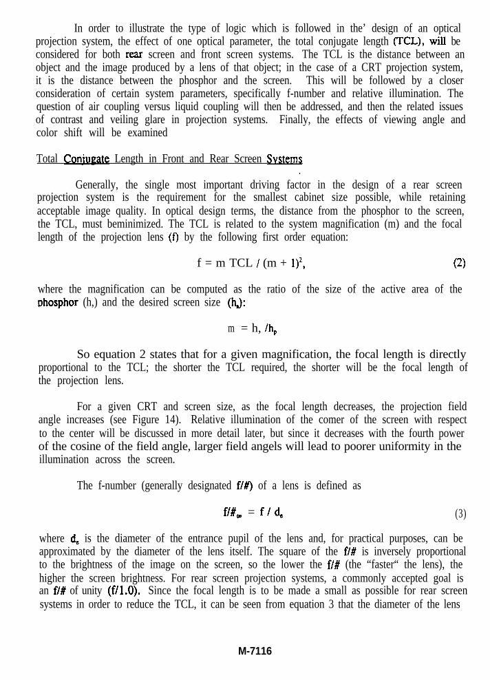
In order to illustrate the type of logic which is followed in the’ design of an opticalprojection system, the effect of one optical parameter, the total conjugate length (TCL), wilI beconsidered for both rear screen and front screen systems. The TCL is the distance between anobject and the image produced by a lens of that object; in the case of a CRT projection system,it is the distance between the phosphor and the screen. This will be followed by a closerconsideration of certain system parameters, specifically f-number and relative illumination. Thequestion of air coupling versus liquid coupling will then be addressed, and then the related issuesof contrast and veiling glare in projection systems. Finally, the effects of viewing angle andcolor shift will be examined
Total Coniuae Length in Front and Rear Screen Svstems.
Generally, the single most important driving factor in the design of a rear screenprojection system is the requirement for the smallest cabinet size possible, while retainingacceptable image quality. In optical design terms, the distance from the phosphor to the screen,the TCL, must beminimized. The TCL is related to the system magnification (m) and the focallength of the projection lens (f) by the following first order equation:
f = m TCL / (m + l)*, (2)
where the magnification can be computed as the ratio of the size of the active area of theohosphor (h,) and the desired screen size (4):
m = h, /h,
So equation 2 states that for a given magnification, the focal length is directlyproportional to the TCL; the shorter the TCL required, the shorter will be the focal length ofthe projection lens.
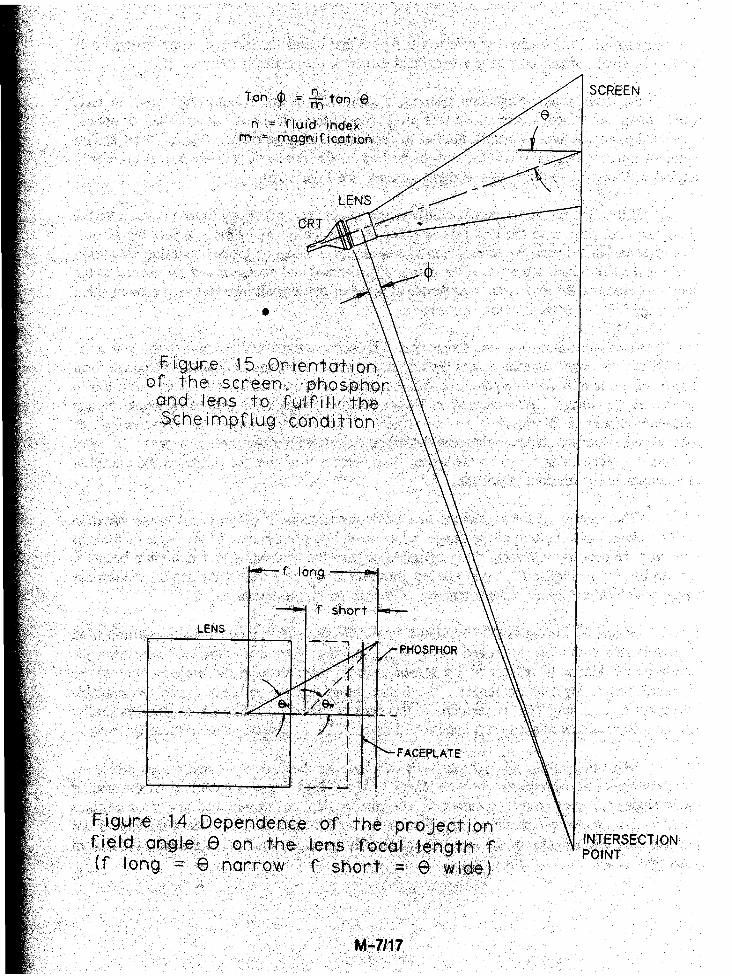
For a given CRT and screen size, as the focal length decreases, the projection fieldangle increases (see Figure 14). Relative illumination of the comer of the screen with respectto the center will be discussed in more detail later, but since it decreases with the fourth powerof the cosine of the field angle, larger field angels will lead to poorer uniformity in theillumination across the screen.
The f-number (generally designated f/#) of a lens is defined as
fl#, = f/d, (3)
where d, is the diameter of the entrance pupil of the lens and, for practical purposes, can beapproximated by the diameter of the lens itself. The square of the f/# is inversely proportionalto the brightness of the image on the screen, so the lower the f/# (the “faster“ the lens), thehigher the screen brightness. For rear screen projection systems, a commonly accepted goal isan f/# of unity (f/1.0). Since the focal length is to be made a small as possible for rear screensystems in order to reduce the TCL, it can be seen from equation 3 that the diameter of the lens
M-7116
will decrease proportionately. In effect, this means that lenses for rear projection systems willtend to be small, which may have a beneficial effect on the cost of the lens itself.
For front screen projection systems, a short TCL is not a requirement and, in fact,would often be an inconvenience. In rear projection systems, it is possible to make the opticalaxis of the lens normal or nearly normal to the screen using mirrors. But for front screensystems, mirrors would obstruct the view of the image. Consequently, the lens axis is invariablyangled with respect to the screen in these systems (see Figure 2b).
If the lens axis is not perpendicular to the screen, it is necessary to tilt the plane of thephosphor with respect to the lens axis in order to keep the image in focus across the screen,The relationship between the screen, lens and phosphor is given by the Scheimpflug Condition(see Figure 15), which states that if the planes of the screen and phosphor and the normal to thelens axis crossing the axis at the rear principal plane of the lens all intersect in one point, thenthe image will be in focus across the screen. a
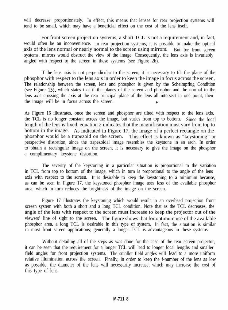
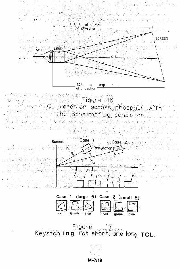
As Figure 16 illustrates, once the screen and phosphor are tilted with respect to the lens axis,the TCL is no longer constant across the image, but varies from top to bottom. Since the focallength of the lens is fixed, equation 2 indicates that the magnification must vary from top tobottom in the image. As indicated in Figure 17, the image of a perfect rectangle on thephosphor would be a trapezoid on the screen. This effect is known as “keystoning” orperspective distortion, since the trapezoidal image resembles the keystone in an arch. In orderto obtain a rectangular image on the screen, it is necessary to give the image on the phosphora complimentary keystone distortion.
The severity of the keystoning in a particular situation is proportional to the variationin TCL from top to bottom of the image, which in turn is proportional to the angle of the lensaxis with respect to the screen. It is desirable to keep the keystoning to a minimum because,as can be seen in Figure 17, the keystoned phosphor image uses less of the available phosphorarea, which in turn reduces the brightness of the image on the screen.
Figure 17 illustrates the keystoning which would result in an overhead projection frontscreen system with both a short and a long TCL condition. Note that as the TCL decreases, theangle of the lens with respect to the screen must increase to keep the projector out of theviewers’ line of sight to the screen. The figure shows that for optimum use of the availablephosphor area, a long TCL is desirable in this type of system. In fact, the situation is similarin most front screen applications; generally a longer TCL is advantageous in these systems.
Without detailing all of the steps as was done for the case of the rear screen projector,it can be seen that the requirement for a longer TCL will lead to longer focal lengths and smallerfield angles for front projection systems. The smaller field angles will lead to a more uniformrelative illumination across the screen. Finally, in order to keep the f-number of the lens as lowas possible, the diameter of the lens will necessarily increase, which may increase the cost ofthis type of lens.
M-711 8
T C L at botstom , . J
7 \ SCREEN
\
:. ,-.
*\ \
rcl. ot .tf&p " -
of phosphor. . ; ,
Figure~“~16
Case IA, _;Screen. j
Case 1) (large 8) Case 2 (
pJHz!@q hzi-l*-Egi-oetl blue
.,
FiQure 1Keydon i n g fbr sho&,-and lor
I - I I I .I I
1 :
small 6)’
,xilgreen blue
17. ‘.,.lg TCL.
f-Number of the Proiection Lens
As has been stated in the previous section, it is desirable to minimize the f-number ofthe projection lens in order to maximize the brightness of the image on the screen. However,low f-number lenses pose certain problems in design and manufacture, both of which affect thecost of the lenses. Some of these problems will be examined here.
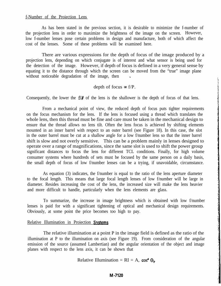
There are various expressions for the depth of focus of the image produced by aprojection lens, depending on which conjugate is of interest and what sensor is being used forthe detection of the image. However, if depth of focus is defined in a very general sense byequating it to the distance through which the screen can be moved from the “true” image planewithout noticeable degradation of the image, then 8 *
depth of focus 0~ f/P.
Consequently, the lower the f/# of the lens is the shallower is the depth of focus of that lens.
From a mechanical point of view, the reduced depth of focus puts tighter requirementson the focus mechanism for the lens. If the lens is focused using a thread which translates thewhole lens, then this thread must be fine and care must be taken in the mechanical design toensure that the thread allows no lens tilt. Often the lens focus is achieved by shifting elementsmounted in an inner barrel with respect to an outer barrel (see Figure 18). In this case, the slotin the outer barrel must be cut at a shallow angle for a low f/number lens so that the inner barrelshift is slow and not overly sensitive. This can be a problem mainly in lenses designed tooperate over a range of magnifications, since the same slot is used to shift the power groupsignificant distances to focus the lens for different TCL conditions. Finally, for high volumeconsumer systems where hundreds of sets must be focused by the same person on a daily basis,the small depth of focus of low f/number lenses can be a trying, if unavoidable, circumstance.
As equation (3) indicates, the f/number is equal to the ratio of the lens aperture diameterto the focal length. This means that large focal length lenses of low f/number will be large indiameter. Resides increasing the cost of the lens, the increased size will make the lens heavierand more difficult to handle, particularly when the lens elements are glass.
To summarize, the increase in image brightness which is obtained with low f/numberlenses is paid for with a significant tightening of optical and mechanical design requirements.Obviously, at some point the price becomes too high to pay.
Relative Illumination in Proiection Svstems
The relative illumination at a point P in the image field is defined as the ratio of theillumination at P to the illumination on axis (see Figure 19). From consideration of the angularemission of the source (assumed Lambertian) and the angular orientation of the object and imageplanes with respect to the lens axis, it can be shown that
Relative Illumination = RI = A, cos4 8,
M -7120
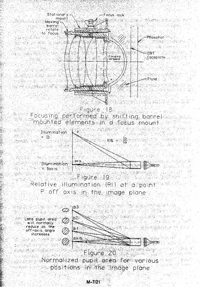
where 4. is the normalized area of the vignetted pupil viewed from p (see Figure 20) and epis the angle of the chief ray from P, or what has been called the projection field angle.
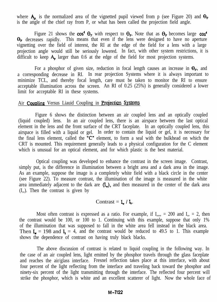
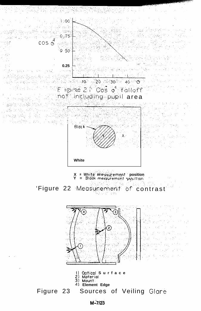
Figure 21 shows the cos4 ep with respect to OF. Note that as 0, becomes large cos4ep decreases rapidly. This means that even if the lens were designed to have no aperturevignetting over the field of interest, the RI at the edge of the field for a lens with a largeprojection angle would still be seriously lowered. In fact, with other system restrictions, it isdifficult to keep 4 larger than 0.6 at the edge of the field for most projection systems.
For a phosphor of given size, reduction in focal length causes an increase in 0,+ anda corresponding decrease in RI. In rear projection Systems where it is always important tominimize TCL, and thereby focal length, care must be taken to monitor the RI to ensureacceptable illumination across the screen. An RI of 0.25 (25%) is generally considered a lowerlimit for acceptable RI in these systems.
Air Coupling Versus Liauid Coupling in Projection Systems
Figure 6 shows the distinction between an air coupled lens and an optically coupled(liquid coupled) lens. In an air coupled lens, there is an airspace between the last opticalelement in the lens and the front surface of the CRT faceplate. In an optically coupled lens, thisairspace is filled with a liquid or gel. In order to contain the liquid or gel, it is necessary forthe final lens element, called the “C” element, to form a seal with the bulkhead on which theCRT is mounted. This requirement generally leads to a physical configuration for the C elementwhich is unusual for an optical element, and for which plastic is the best material.
Optical coupling was developed to enhance the contrast in the screen image. Contrast,simply put, is the difference in illumination between a bright area and a dark area in the image.As an example, suppose the image is a completely white field with a black circle in the center(see Figure 22). To measure contrast, the illumination of the image is measured in the whitearea immediately adjacent to the dark are &,), and then measured in the center of the dark area(I,,). Then the contrast is given by
Contrast = I, / Ib.
Most often contrast is expressed as a ratio. For example, if I,,,, = 200 and I,, = 2, thenthe contrast would be 100, or 100 to 1. Continuing with this example, suppose that only 1%of the illumination that was supposed to fall in the white area fell instead in the black area.Then I, = 198 and Ib = 4, and the contrast would be reduced to 49.5 to 1. This exampleshows the dependence of contrast on having truly black blacks.
The above discussion of contrast is related to liquid coupling in the following way. Inthe case of an air coupled lens, light emitted by the phosphor travels through the glass faceplateand reaches the air/glass interface. Fresnel reflection takes place at this interface, with aboutfour percent of the light reflecting from the interface and traveling back toward the phosphor andninety-six percent of the light transmitting through the interface. The reflected four percent willstrike the phosphor, which is white and an excellent scatterer of light. Now the whole face of
M -7122
.cos s”
” J”
_ \
’ 0.25;
i- ‘Y’-- ’ I ”A,.4UIC Li ‘J-- -
Bfuc
pil a r e a
k
White
X = While m eY = Block met
merit _ position.P.c..T+ m-r :+;A-.
‘F igure 22 ,Mea: 1 I J c o n t r a s t
-,u~l-l
:
)tical S u r f a c e. . .1) OF23,’ ;zdslai
41, Element Edge
Figure 23 Sources of Vei l ing Glare
w7123
the phosphor, light and dark areas alike, will have an increased brightness due to the lightreflected at the interface (see Figure 5). Light which strikes the light areas of the phosphor areunimportant, but that which strikes the dark areas will have a very detrimental effect on thecontrast in the image, as was shown by the brief example above.
In an optically coupled lens, the air/glass interface is replaced by a liquid/glassinterface. Since the amount of Fresnel reflection is proportional to the difference in index ofrefraction on the two sides of the interface, it is dramatically reduced in this case. For example,for a faceplate index of 1 S37 and a liquid index of 1.443, the Fresnel reflection is reduced fromthe 4% of a -glass/air interface to well under 1%. Generally, the end result in terms of thecontrast measured on the screen is on the order of a fortypercent improvement in contrast.
There are other consequences of using a liquid coupled lens. On the positive side, thereis no need for a liquid cooled tube if a liquid is used for the optical coupling, since the couplingfluid itself can serve as the coolant with proper bulkhead design. On the negative side, thebulkhead design and manufacture are more complicated, since a liquid must be dealt with in anarea invariably packed with electronic components. Also, if the lens axis is tilted with respectto the screen, a Scheimpflug tilt must be applied to the CRT, and in the liquid coupled case, thistilt must be applied across an interface that has a liquid-tight seal. However, the dramaticimprovement in contrast afforded by liquid coupling outweigh the disadvantages in the opinionof many projection system manufacturers, judging by the number of systems on the marketwhich utilize this feature.
VeilinP Glare in Proiection Systems
Veiling glare is another effect which can have a dramatic effect on the contrast of aprojection system. Veiling glare is non-imaging light from the source which is scattered by theoptical system and uniformly illuminates the screen. Continuing with the example used above,suppose that J, = 200 and I, = 2, giving a contrast ratio of 100 to 1. Now suppose that onlyone unit of non-imaging light is scattered by the system uniformly across the screen. In thiscase, I, = 201 and I, = 3, giving a contrast ratio of 67 to 1. Very little veiling glare can havea very significant effect on image contrast.
The sources of veiling glare are shown schematically in Figure 23. Optical surfaces aresources of scattered light if they contain dirt, grease, fingerprints, scratches, or imperfect orhazy coatings. The material with which the optical elements are made, glass or plastic, aresources of veiling glare if they contain inhomogeneities, bubbles, inclusion, or haze. Note thatin both of the above sources, haze is by far the most damaging problem, since it tends to beexhibited over larger areas that the other defects noted. The edges of optical elements can bea source of scattered light in the system if they are improperly stopped with mount apertures.In cases where it is not possible to completely stop the light from an element edge, the edgemust be painted a flat black, light-absorbing material. Finally, the mount itself can be a sourceof scattered light if stops and anti-reflection threads are improperly designed or if internalsurfaces are not effectively blackened.
M-7124
There is no Universal cure for veiling glare in a system. Its sources are many, and theymust be pursued individually. Vendors of optical materials must supply clean material. mefabrication of the optical surfaces and coatings must be flawless, and subsequent handling adstorage must be performed with great care. Mounts and element edges must be designed to stopall non-imaging light which enters the system; there are several optical design programscommercially available which can aid in this design, not to mention the many proprietaryprograms in use. Only through constant attention to all of these areas can veiling glare bereliably controlled.
Viewing Angle and Color Shift ‘1
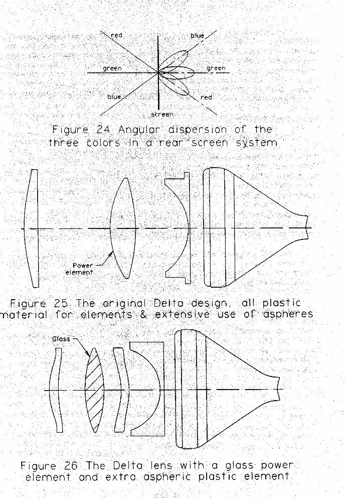
Figure la is a diagram of a three-tube projection system. Note that all three channels,green, red, and blue, have a different angle of incidence with respect to the screen. Figure 24shows angular dispersion patterns of the light transmitted by the screen for each channel.Ideally, these patterns would overlap, so that a viewer would receive the same proportion ofeach color regardless of his viewing position. Since the angular dispersion patterns do notoverlap, the relative color mix will vary depending on the angle of the viewing axis with respectto the screen. This dependence of the color mix on viewing angle is known as color shift.
Color shift can occur in both rear screen and front screen systems. In fact, any multi-channel optical system where the different channels take different optical paths to the screen issubject to this problem. There are basically two ways to approach the color shift problem.
First, and as a general rule, the angle of incidence of the various channels with respectto the screen should be made as constant as possible. This design principle will not only’minimize the color shift problem, but also will ensure optimum phosphor coverage for thedifferent colors and greatly reduce convergence problems in the final set.
Second, some means can be taken to ensure that& angular dispersion of the lightwhich is scattered by the screen is constant regardless of the angle of the light incident on thescreen. In front screen systems, this can be accomplished by manipulating the gain of thescreen, as was indicated in the section concerning screen design. For rear screen systems, thedesign of the different screen “layers” (see Figure 13) is manipulated to attempt to bring thethree channels into coincidence. However, the problem is a difficult one, and every attemptshould be made to minimize the difference between the incidence angles of the three channelsto the screen when possible.
M -7125
Lens Design for Proiection Svstems
Qntical Performance Requirements
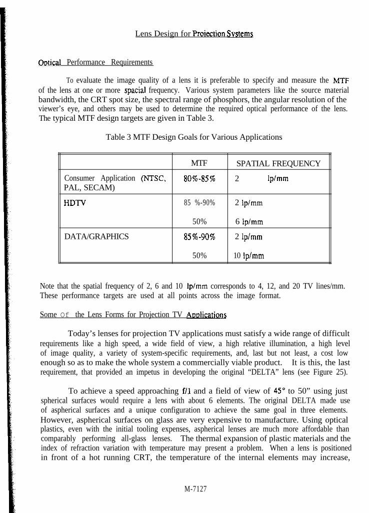
To evaluate the image quality of a lens it is preferable to specify and measure the MTFof the lens at one or more spatial frequency. Various system parameters like the source materialbandwidth, the CRT spot size, the spectral range of phosphors, the angular resolution of theviewer’s eye, and others may be used to determine the required optical performance of the lens.The typical MTF design targets are given in Table 3.
Table 3 MTF Design Goals for Various Applications
Consumer Application (NTSC,PAL, SECAM)
HDTV
DATA/GRAPHICS
MTF SPATIAL FREQUENCY
80%-85% 2 lp/mm
85 %-90% 2 lp/mm
50% 6 lpimm
85%-90% 2 lplmm
50% 10 lp/mm
Note that the spatial frequency of 2, 6 and 10 lp/mm corresponds to 4, 12, and 20 TV lines/mm.These performance targets are used at all points across the image format.
Some Of the Lens Forms for Projection TV ADDlications
Today’s lenses for projection TV applications must satisfy a wide range of difficultrequirements like a high speed, a wide field of view, a high relative illumination, a high levelof image quality, a variety of system-specific requirements, and, last but not least, a cost lowenough so as to make the whole system a commercially viable product. It is this, the lastrequirement, that provided an impetus in developing the original “DELTA” lens (see Figure 25).
To achieve a speed approaching f/l and a field of view of 45” to 50” using justspherical surfaces would require a lens with about 6 elements. The original DELTA made useof aspherical surfaces and a unique configuration to achieve the same goal in three elements.However, aspherical surfaces on glass are very expensive to manufacture. Using opticalplastics, even with the initial tooling expenses, aspherical lenses are much more affordable thancomparably performing all-glass lenses. The thermal expansion of plastic materials and theindex of refraction variation with temperature may present a problem. When a lens is positionedin front of a hot running CRT, the temperature of the internal elements may increase,
M-7127
Depending on the configuration of the lens and the configuration of the system as a whole, thetemperature on the surface of some of the elements may change by as much as 30°C to 40°C.This, in turn, may cause an appreciable change in the focal length of the lens and acorrespondingly noticeable focus shift.
It is possible to compensate for this thermal drift of focus by various mechanical meansusing bi-metal devices or supplementary motors to achieve an appropriate displacement of someof the internal elements of the lens or by moving the lens as a whole. However, since thedominant effect of the change in temperature is the change in the refractive index, the easiestway to minimize this drift of focus is to replace the strongest element or elements in the lenswith a more thermally stable material - glass. For economical reasons, surfaces of the glasselements are spherical. Consequently, to achieve the required level of correction of aberrations,it may be necessary to add another plastic aspherical element. A DELTA lens with thesemodifications is shown in Figure 26.
Note that in this form of the lens the strongest element is made out of glass and the restof the elements are made out of acrylic with a minimum of optical power in each of them. T h ethermal focus drift of this lens is well under control. Lenses with both plastic and glasselements are called “hybrid” lenses.
To achieve a low lens cost, the most common and easiest to work glasses like BK7, SK5and, occasionally, SK18 are used. When it is necessary to provide some correction of chromaticaberrations, an F2 flint is used, though often the choice of flints is wider since they do not differsignificantly in price.
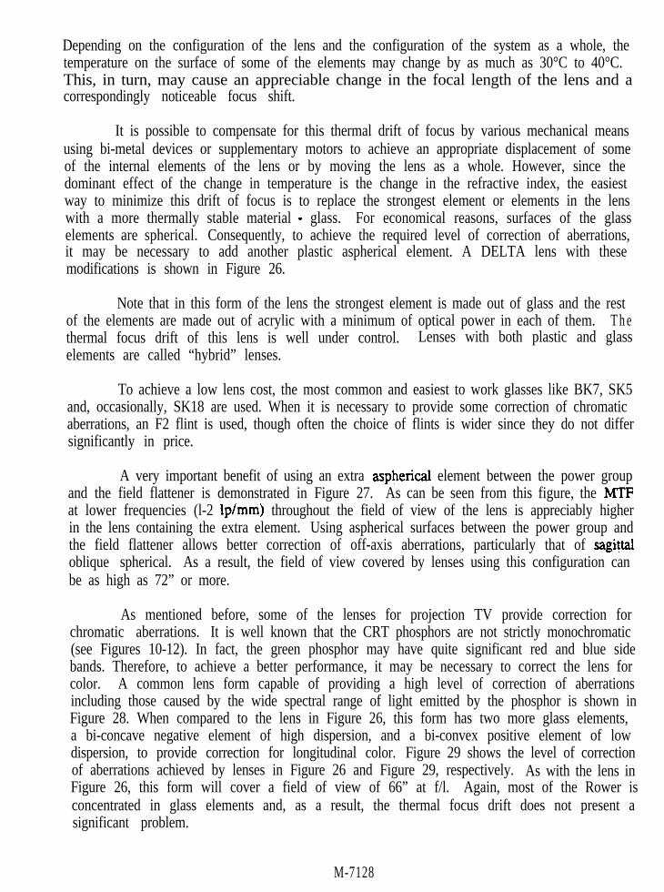
A very important benefit of using an extra aspherical element between the power groupand the field flattener is demonstrated in Figure 27. As can be seen from this figure, the MTFat lower frequencies (l-2 lp/mm) throughout the field of view of the lens is appreciably higherin the lens containing the extra element. Using aspherical surfaces between the power group andthe field flattener allows better correction of off-axis aberrations, particularly that of sag&aloblique spherical. As a result, the field of view covered by lenses using this configuration canbe as high as 72” or more.
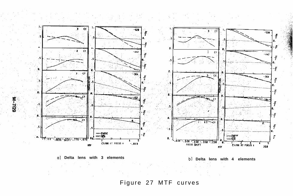
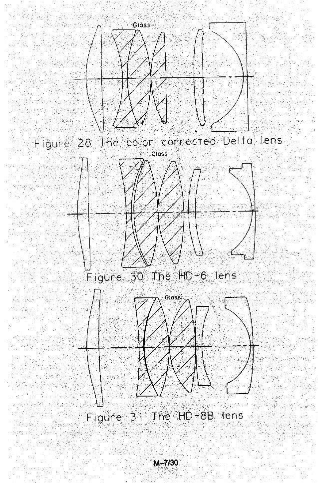
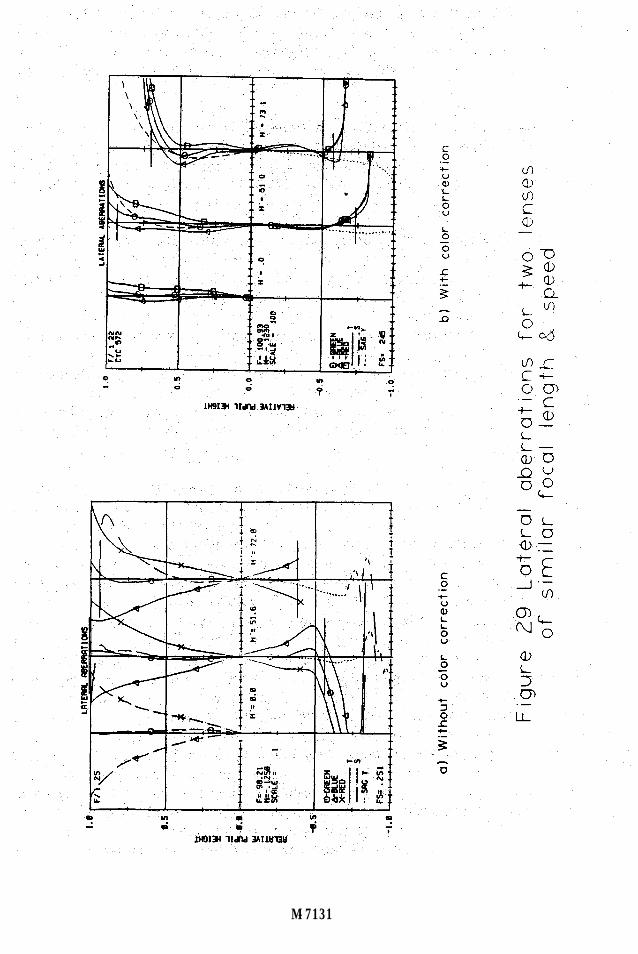
As mentioned before, some of the lenses for projection TV provide correction forchromatic aberrations. It is well known that the CRT phosphors are not strictly monochromatic(see Figures 10-12). In fact, the green phosphor may have quite significant red and blue sidebands. Therefore, to achieve a better performance, it may be necessary to correct the lens forcolor. A common lens form capable of providing a high level of correction of aberrationsincluding those caused by the wide spectral range of light emitted by the phosphor is shown inFigure 28. When compared to the lens in Figure 26, this form has two more glass elements,a bi-concave negative element of high dispersion, and a bi-convex positive element of lowdispersion, to provide correction for longitudinal color. Figure 29 shows the level of correctionof aberrations achieved by lenses in Figure 26 and Figure 29, respectively. As with the lens inFigure 26, this form will cover a field of view of 66” at f/l. Again, most of the Rower isconcentrated in glass elements and, as a result, the thermal focus drift does not present asignificant problem.
M-7128
3. .3 Cl
s. _*..-
- - -
I I- 1 . 0 8 -.979 -.8?9 -.?79 -.679 8. I -T 4n. 2 I3
4 50. *
F O C U S SWFT -.638 -.538 -CYIlltl
WTFA T FOCUS = -.613 FOCUS SHIFT
ftTF
0.
CYmH RT FCCU~ =
a) Delta lens with 3 elements b) Delta lens with 4 elements
F igu re 27 MTF cu rves
M-7131
With the CRT spot size approaching 0.1 mm, the projection lenses for HDTV andDATA/GRAPHICS applications must have a maximum MTF at 10 lp/mm. The lens shown inFigure 30 is capable of providing this level of performance. It has been sold for a number ofyears under the name HD-6. The field of view of the lens is 46”, it covers 5” raster diagonalon the CRT.
To increase the amount of light and achieve a high resolution on the screen, larger CRTsizes are often used. Consequently, projection lenses must increase their field of view or focallength. In practice, both variables are considered. The lens shown in Figure 31 is the HD-8Blens covering 5.75” raster diagonal on the CRT. The f/number of the lens is f/l. 1 and the fieldof view is around 52”.
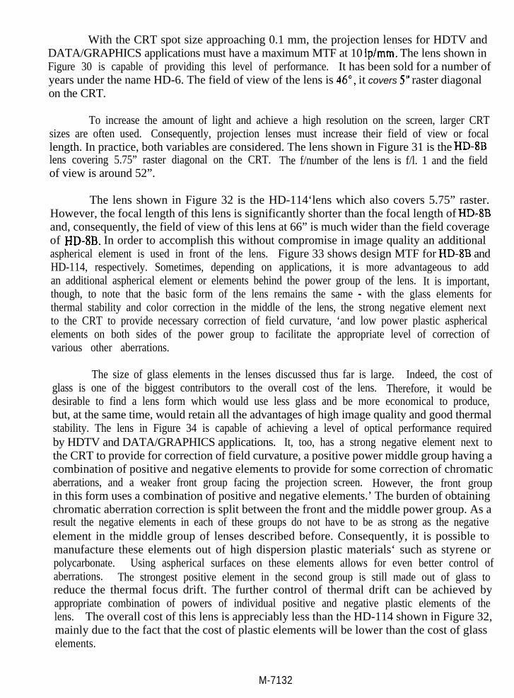
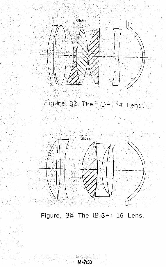
The lens shown in Figure 32 is the HD-114‘lens which also covers 5.75” raster.However, the focal length of this lens is significantly shorter than the focal length of HD-8Band, consequently, the field of view of this lens at 66” is much wider than the field coverageof HD-8B. In order to accomplish this without compromise in image quality an additionalaspherical element is used in front of the lens. Figure 33 shows design MTF for HD-8B andHD-114, respectively. Sometimes, depending on applications, it is more advantageous to addan additional aspherical element or elements behind the power group of the lens. It is important,though, to note that the basic form of the lens remains the same - with the glass elements forthermal stability and color correction in the middle of the lens, the strong negative element nextto the CRT to provide necessary correction of field curvature, ‘and low power plastic asphericalelements on both sides of the power group to facilitate the appropriate level of correction ofvarious other aberrations.
The size of glass elements in the lenses discussed thus far is large. Indeed, the cost ofglass is one of the biggest contributors to the overall cost of the lens. Therefore, it would bedesirable to find a lens form which would use less glass and be more economical to produce,but, at the same time, would retain all the advantages of high image quality and good thermalstability. The lens in Figure 34 is capable of achieving a level of optical performance requiredby HDTV and DATA/GRAPHICS applications. It, too, has a strong negative element next tothe CRT to provide for correction of field curvature, a positive power middle group having acombination of positive and negative elements to provide for some correction of chromaticaberrations, and a weaker front group facing the projection screen. However, the front groupin this form uses a combination of positive and negative elements.’ The burden of obtainingchromatic aberration correction is split between the front and the middle power group. As aresult the negative elements in each of these groups do not have to be as strong as the negativeelement in the middle group of lenses described before. Consequently, it is possible tomanufacture these elements out of high dispersion plastic materials‘ such as styrene orpolycarbonate. Using aspherical surfaces on these elements allows for even better control ofaberrations. The strongest positive element in the second group is still made out of glass toreduce the thermal focus drift. The further control of thermal drift can be achieved byappropriate combination of powers of individual positive and negative plastic elements of thelens. The overall cost of this lens is appreciably less than the HD-114 shown in Figure 32,mainly due to the fact that the cost of plastic elements will be lower than the cost of glasselements.
M-7132
-- .3-t--
Figure, 34: The B&-P 16 Lens.
d
2 0.0
Ew.
ii!
-0.5
-1.0
a l HO- 114
t
- 1 . 0
b) IBIS.
Figure 3 5 L a t e r a l aberrat ion curves
u-l
\‘\ F-4
HI: .... i4\ ‘.\ ‘.., . .\ ‘,.
:
D,?
/ I
coM
M-7139
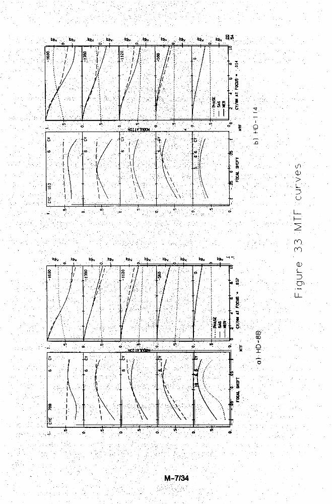
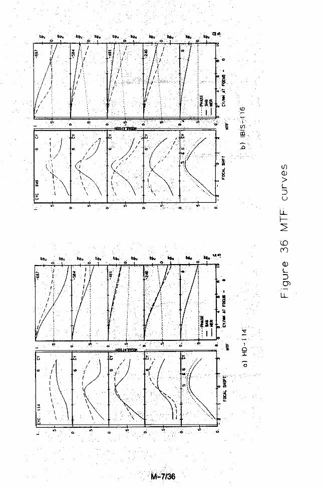
The disadvantage of using this form of the lens is that it may take longer to prepare forproduction since the number of plastic elements is increased and the corresponding tooling ismore involved. It is also important to know more precisely the temperature distribution insidethe lens since the plastic elements’ powers may be reasonably strong and the thermal focus driftmay become severe if the individual powers are not balanced appropriately. The data in Figure35 and Figure 36 shows the optical performance of the two lenses having the identical speed andthe field of view. One of these lenses is HD-114 having three glass element in the power groupand the other one is IBIS-l 16 having only one glass element. As can be seen, these lenses arenearly identical in image quality; however, the cost of IBIS lenses is appreciably lower than thatof HD-114.
1)
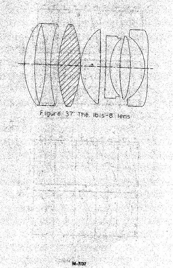
An important consideration which has to be taken into account during the optical designof a lens is the range of magnifications over which this lens must be used. Today some of thesame methods and techniques used to design zoom lenses are applied to achieve a greaterstability of image quality with change of magnifications. Lenses for rear projection sets mustwork at discreet magnifications corresponding to standard screen sizes ranging from 40” diagonalto 70” diagonal. The optically coupled lenses which are used predominately in rear projectionapplications tend to not focus well, especially when the field of view of the lens is very wide.In those instances the lens is designed to work in a limited range of magnifications, and one ofthe elements is then modified to correct for changes in spherical aberration and astigmatism tomake the modified lens cover the remaining focusing range. The front projection lenses areoften used from about 70” screen diagonal up to 350” diagonal. These lenses may need to befocused continuously to adapt to various projection set-ups. To do so, these lenses may use oneor more variable internal spaces to achieve a good image quality over a wide range ofmagnifications. The example of such a lens is shown in Figure 37.
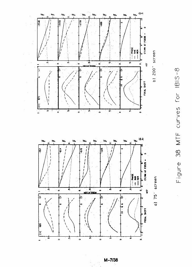
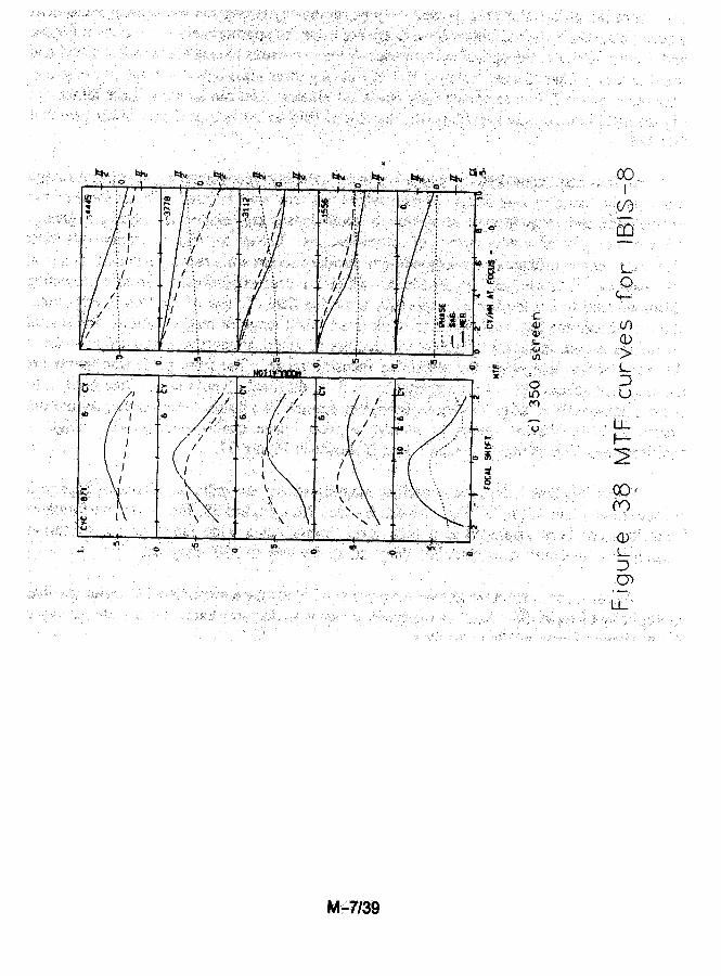
When this lens is focused at various magnifications, the indicated airspaces change ina predetermined non-linear fashion. As can be seen from Figure 38, the optical performanceof this lens has been stabilized at a high level throughout a wide range of magnificationscorresponding to screen sizes from 75” diagonal all the way to 350” diagonal.
As can be seen from the above, the process of designing a projection TV optics involvesa multiplicity of tradeoffs. And, as expected, every manufacturer today has a wide variety ofCRT projection lenses available to them.
M -7140