Embed Size (px)
Citation preview
Paage | 1
(Cla
US & Caass I, II,
HI 60
anada HIII, Divis
Hardy Process
C
C
020IT an
azardousion 1, C
Solutions Docu
CONTROL
CHANGES WITHOUT
CERTIFI
nd HI 60
us Locatilass I, Zo
ument Number:
LLED DO
MAY NOTT APPROVAICATION A
H
020JB
ions Useone 0 an
: 0596-0352-01 R
OCUMENT
T BE MADEAL FROM
AGENCY
I 6020IT and HI
er Guidend Zone
REV A
T
E
6020JB User Gu
e 20)
ide
Paage | 2
OBSE
ERVE PRECAU
DO NOT INSTHE AREA BEEN SECUSO BY THE
INSTALLAT“INSTALLAT(CLASSIFIE70) ARTICL WHEN THISSYSTEM, TPERSONNEOPERATIONHAZARDS RESULT IN
ALL EQUIPINSTALLATOR SUBSINSTRUCTICOULD RES
TO PREVENDISCONNEC
FOR CONTIINTRINSICACONNECTIO
UTIONS FOR H
STALL OR PEIN WHICH TH
URED AS NON RESPONSIBL
ION SHOULD TION OF INTRED) LOCATIONE 504.
S SUMMING THE RESULTEL WHO ARN OF ALL COINVOLVED. FBODILY HARM
PMENT MUSION INSTRUC
STITUTE COONS CAN IMPSULT IN BODI
NT IGNITION OCT POWER B
INUED PROTEALLY SAFE GRON.
HANDLING EL
WAERFORM ANY HE HI 6020 JBN-HAZARDOULE PERSON A
WABE IN ACCOR
RINSICALLY SANS” AND THE E
BOX IS INCLTING DESIGNRE FAMILIAROMPONENTS FAILURE TO M AND/OR PR
WAST BE INSTCTIONS DETAMPONENTS PAIR THE INSLY INJURY AN
WA
OF FLAMMABLEFORE SERV
WAECTION AGAINROUND ONLY
CAUT
ECTROSTATI
H
ARNINGSERVICE ON
B OR IT SUMMUS BY PERSOAT THE CUSTO
ARNINGRDANCE WITHAFE SYSTEM ELECTRICAL S
LUDED AS A MUST BE R WITH THIN THE SYSOBSERVE T
ROPERTY DAM
ARNINGTALLED IN AAILED IN THIS
AND/OR DSTRINSIC SAFND/OR PROPE
ARNING
LE OR COMBUVICING
ARNINGNST SHOCK H
Y. DO NOT REM
ION
C SENSITIVE
I 6020IT and HI
G!
N THIS EQUIPMMING BOX IS ONNEL AUTHOOMER’S SITE
G!
H ANSI/ISA RPFOR HAZARDSAFETY COD
COMPONENREVIEWED B
HE CONSTRSTEM AND THTHIS PRECAUMAGE.
G!
ACCORDANCES USER GUIDE
EVIATION FFETY OF THEERTY DAMAG
G!
USTIBLE ATM
G!
HAZARD, CONMOVE THE GR
DEVICES.
6020JB User Gu
MENT BEFORLOCATED HA
ORIZED TO D
P12.06.01 DOUS E (ANSI/NFA
T PART OF BY QUALIFIE
RUCTION ANHE POTENTIAUTION COUL
E WITH THE. INCORRECFROM THESE DEVICE ANE.
OSPHERES,
NNECT TO THEROUNDING
ide
RE AS
O
A D D
AL D
HE CT SE
D
E
HI 6020IT and HI 6020JB User Guide
Page | 3
Contents • • • • • •
Contents ............................................................................................................................................................. 3 Chapter 1 ............................................................................................................................................................ 4 HI 6020IT and HI 6020JB Overview .................................................................................................................... 4
Introduction to the HI 6020IT and HI 6020JB Summing Boxes ............................................ 4 Chapter 2 .............................................................................................................................................................. 5 Specifications and Features ..................................................................................................................................... 5
Basic Specifications ................................................................................................................... 5 HI 6020IT and HI 6020JB ................................................................................................ 5 Approvals ......................................................................................................................... 7
Features and Capabilities ............................................................................................................. 7 Hardy Process Toolbox ......................................................................................................... 7 C2® and Calibration ............................................................................................................. 7 INTEGRATED TECHNICIAN® .......................................................................................... 7
Chapter 3 ............................................................................................................................................................ 8 Installation of Intrinsically Safe HI 6020 IT and HI 6020JB Summing Boxes into Hazardous (Classified) Locations ............. 8
Wiring Summing Boxes .............................................................................................................. 8 Connecting to Hardy Summing Boxes or Summing Cards ....................................................... 9 Connecting Load Cell Sensors to a Hardy Summing Box .............................................. 10 Applicable Certification Documents for Intrinsically Safe Protection Techniques ..................... 11 Standards used for evaluation of the HI 6020 summing box series: ............................... 11
HI 6020IT and HI 6020JB User Guide
Page | 4
Chapter 1
HI 6020IT and HI 6020JB Overview • • • • • • This user guide describes installation, setup and operating procedures for the HI 6020IT and HI 6020JB summing boxes. Be sure to read and understand all cautions, warnings, and safety procedures in this user guide to ensure safe installation and operation of the summing boxes. Hardy Process Solutions sincerely appreciates your business. We encourage input about the performance and operation of our products from our customers. Should you not understand any information in this user guide or experience any problems with this product, please contact our Technical Support Department at:
Phone: (858) 278-2900
Toll Free: 1-800-821-5831
FAX: (858) 278-6700
E-Mail: [email protected] or [email protected]
Website: www.hardysolutions.com
Please visit our website for the latest revision of this User Guide and sign up for the Hardy Newsletter to get the latest information on all Hardy products and services. For answers to technical issues and service problems, please visit the Hardy WebTech section of our website or contact a technician by phone during our normal operating hours (6:30 AM to 5:30 PM Pacific Time).
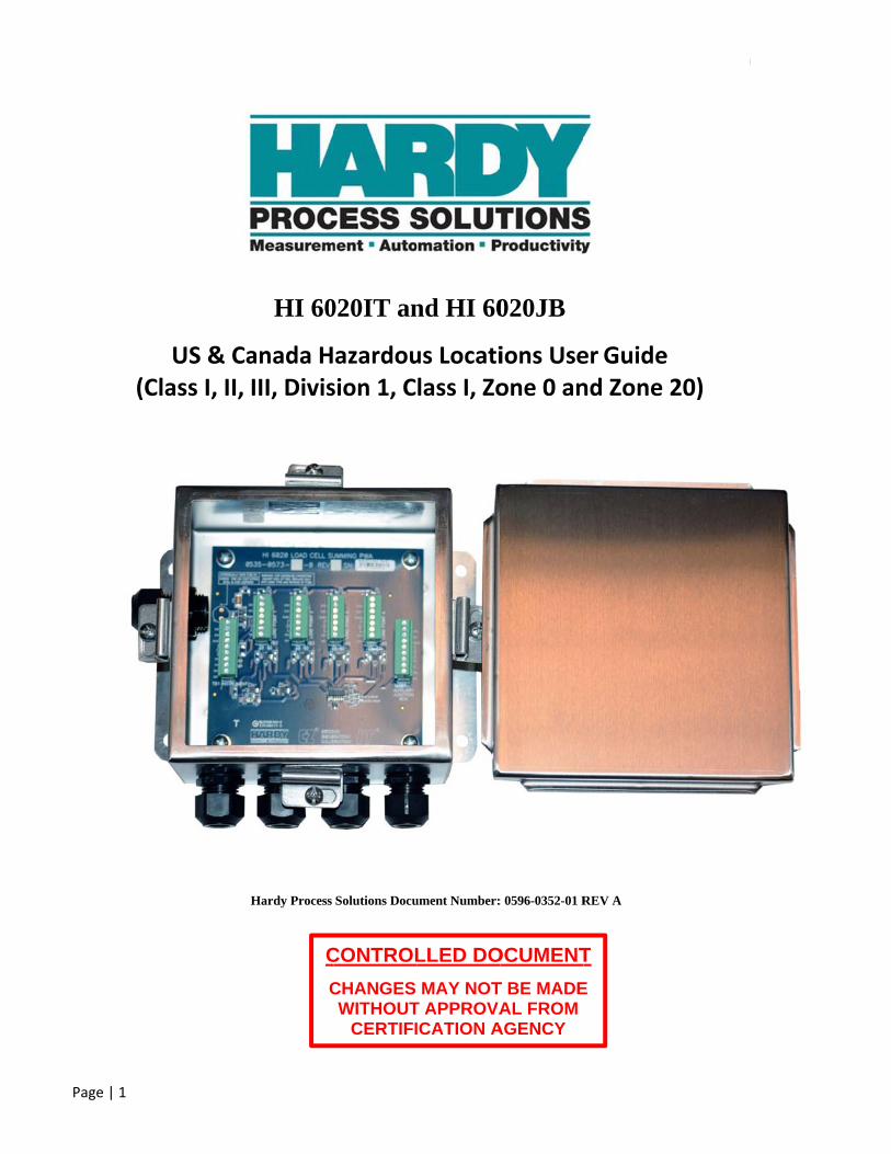
Introduction to the HI 6020IT and HI 6020JB Summing Boxes The Hardy HI 6020 summing box is a critical component in a weighing system that enables use of Hardy’s core technologies - C2® electronic calibration and Integrated Technician® (IT). Each summing box distributes excitation voltage to up to four load cells and transfers each load cell’s performance characteristics and weight signals to the Hardy weighing instrument. A summing card with IT allows a weighing instrument operator to switch to the summing card’s internal test circuit and diagnose the entire weighing system from the front panel of the instrument or a remote location over the Internet. Individual load cells can be isolated from each other for weight and voltage readings, allowing a technician or operator to quickly and safely troubleshoot weighing system faults and anomalies. The HI 6020 Summing box is available with a variety of options, including Integrated Technician® (IT) and trim pots (for non-Hardy load cells). The UL Type 4/4X stainless steel enclosure features a thick-wall design with an interior seal for a long lasting, robust wash-down installation. Two configurations are available, a 5-hole version for connecting up to four load cells to a Hardy weight indicator, controller, or module; or a 6-hole version that connects to a second HI 6020 summing box to enable up to eight load cells to be connected to a Hardy weight indicator or controller. The HI 6020 summing box comes with four packaged hole-plugs, six cable grip fittings, suitable for load cell cables with an outside diameter of 4.3mm to 11.4mm.
HI 6020IT and HI 6020JB User Guide
Page | 5
Chapter 2
Specifications and Features • • • • • • Chapter 2 provides specifications for HI 6020 Summing Box series instruments. The specifications listed are designed to assist in the installation, operation and troubleshooting of your summing box. All service personnel should be familiar with this section before installing or repairing the instrument.
Basic Specifications There are two main configurations for the HI 6020 summing box.
1. The HI 6020JB which includes a summing board without INTEGRATED TECHNICIAN® (IT) 2. The HI 6020IT which includes a summing board with INTEGRATED TECHNICIAN® (IT)
The HI 6020JB-SSX-Y provide different options. Where:
SS: stainless steel enclosure X: X= 1 without trim pots or X= 2 with trim pots Y: Y = blank is a 5-hole summing box enclosure Y = 6 is a 6-hole summing box enclosure enabling connection to a second summing box
The HI 6020JB and HI 6020IT is provided with cable glands and has approval for use in the following hazardous areas: Class I, Division 1, Groups A, B, C, D, T4 Class II, Division 1, Groups E, F, G, T4 Class III, Division 1, T4 Class I, Zone 0, Group IIC, T4 Class II, Zone 20, Group IIIC, T4 Class I, Division 2, Groups A, B, C, D, T5 Class II, Division 2, Groups F, G, T5 Class III, Division 2, T5
IMPORTANT NOTE: Only the stainless steel versions of the HI 6020JB and HI 6020IT junction boxes are certified for use in hazardous areas.
HI 6020IT and HI 6020JB Number of Load Cells Supported
8 (requires two summing boxes, one 6-hole summing box and one 5-hole summing box) 4 (requires only one 5-hole summing box)
Enclosure
Stainless Steel PCB Dimensions
4.88" (12.38 cm) x 4.88" (12.38 cm)
HI 6020IT and HI 6020JB User Guide
Page | 6
Connector Type
Removable Plug-In Terminal Blocks
4 off, 7 pin, 1 row, 3.5 mm pitch (load points)
2 off, 9 pin, 1 row, 3.5 mm pitch (instrument and auxiliary ports) Temp Range
-10 to +60°C (14 to 140°F)
Maximum Excitation Voltage and estimated Excitation Current The maximum excitation voltage, on the summing box side of the IS barrier, is 5VDC. The maximum excitation current is 70mA under normal operating conditions, and is limited to 100mA by the selected IS barriers. The required IS barrier supply voltage and actual excitation current drawn for a load cell weighing system, depends upon the IS barriers selected, the load cell resistance, the cable length between the excitation voltage source and the summing box, the number of summing boxes, and the number of load cells required for the weighing system. Please review the installation section for additional information.
Trim Pot Number of Turns 11 (for use with non-C2 systems)
Trim Pot Impedance Range 0-10 Ω
Power Rating Non Hazardous, Safe area Locations, Class I and II, Division 2 Hazardous and Class III Division 1 and 2 Hazardous (Classified) Locations, and
Class I, Zone 0 and 2 Groups IIC, Zone 20 and 22 Groups IIIC HI 6020IT: 5 VDC, Class 2 source, max. 50 mA HI 6020JB: 2-15 VDC, Class 2 source, max. 275 mA
Class I and II, Division 1 Hazardous (Classified) Locations and Class I, Zone 0 and 2 Groups IIC, Zone 20
and 22 Groups IIIC Power must be supplied to the summing box through approved intrinsically safe barriers per control
drawing 0594-0007 (HI 6020JB) or 0594-0008 (HI 6020IT) HI 6020IT: 5 VDC, Class 2, max. 50 mA HI 6020JB: 5 VDC, Class 2, max. 50 mA
Warranty Two-year warranty against defects in workmanship
Housing Torque Specification Enclosure Bolt Torque Specification: 50-55 in/lb Additional Instruction: Be sure to lubricate (oil) the screw threads to prevent galling of the screw and
enclosure screw flange threads.
HI 6020IT and HI 6020JB User Guide
Page | 7
Approvals CE UL, CUL (ordinary location) Class I, Division 1, Groups A, B, C, D, T4 Class II, Division 1, Groups E, F, G, T4 Class III, Division 1, T4 Class I, Zone 0, Group IIC, T4 Class II, Zone 20, Group IIIC, T4 Class I, Division 2, Groups A, B, C, D, T5 Class II, Division 2, Groups F, G, T5 Class III, Division 2, T5
See control drawing 0594-0007 (HI 6020JB) or 0594-0008 (HI 6020IT) for specific installation instructions
Features and Capabilities
Hardy Process Toolbox The Hardy Process Toolbox is a set of productivity tools that support process weighing functions. Each tool in the Hardy Process Toolbox saves time, increases accuracy, improves efficiency or reduces risk in process weighing applications.
C2® and Calibration Traditional calibration uses certified test weights. C2® Electronic Calibration allows a scale to be calibrated without the need for test weights. A C2 weighing system consists of up to eight load cell sensors per HI 6020 IT or JB summing box, C2 interconnect cable, and a Hardy instrument, controller, or module with C2. Each Hardy Process Solutions C2-certified load sensor outputs digital information used for calculating the calibration. When Hardy instrument reads the signals from the load sensors, it calibrates the scale based on the load sensor’s output plus a user-supplied reference point value (from 0 to any known weight on the scale). NOTE: Check the Hardy instrument, controller, or module to verify the number of load sensors that can be supported.
INTEGRATED TECHNICIAN®
The HI 6020IT features INTEGRATED TECHNICIAN® (IT), a system diagnostics program that makes it possible to diagnose weighing system problems from a Hardy Instrument, controller, or module that reads individual load sensor voltages and weights and isolates individual system components for quick and easy troubleshooting. NOTE: C2 and INTEGRATED TECHNICIAN are registered trademarks of Hardy Process Solutions.
HI 6020IT and HI 6020JB User Guide
Page | 8
Chapter 3
Installation of Intrinsically Safe HI 6020 IT and HI 6020JB Summing Boxes into Hazardous (Classified) Locations • • • • • • This user guide is intended to provide the user with an overview regarding the proper selection of electronic weighing systems used in hazardous locations. This document does not provide details on the installation of equipment as this is typically the responsibility of the installing electrician and/ or engineering design firm. For the latest information please refer to the appropriate set of control drawings which will be one of the item shipped with the summing box.
HI 6020JB series please refer to control drawing 0594-0007 HI 6020IT series please refer to control drawing 0594-0008
Additional copies this user guide and control drawings are available on the Hardy website at: http://www.hardysolutions.com/products/load-cells--platform-scales/accessories/product/511/hi-6020it-and-hi-6020jb-junction-boxes
Wiring Summing Boxes IMPORTANT NOTES when wiring between load cells, summing boxes, and intrinsically safe barriers 1. Associated apparatus manufacturer’s installation drawing must be followed when installing this equipment.
2. Resistance between Intrinsically Safe Ground and earth ground must be less than 1.0 Ohm.
3. Install Intrinsic Safe Barriers in accordance with barrier instructions.
4. The total combined length of all wiring in the system, including the cable from each associated apparatus to and from
the summing box, and to each load cell must not exceed 300 feet.
a. Installation should be in accordance with any applicable local electrical code, which may include ANSI/ISA RP12.06.01 “Installation of Intrinsically Safe System for Hazardous (Classified) Locations,” the electrical Safety code (ANSI/NFPA 70) Article 504.
b. The products for use in both Class I, II, III Division 1 and 2 areas (NEC 501, 502) and Class 1, Zone 0 and 2, Group IIC, and Zone 20 and 22, Group IIIC areas (NEC 505, 506) is the HI 6020JB-SSX-Y and the HI 6020IT-SSX-Y (both shipped with cable glands):
c. SS = Stainless Steel enclosure d. 1 = Without trim pots, 2 = With Trim Pots e. Y= blank is a 5-hole summing box enclosure, and Y=6 is a 6-hole summing box enclosure enabling connection
to a second summing box
5. SB (summing box) maximum cable length 250 ft; used between the summing box and IS barriers.
6. Substitution of components may impair Intrinsic Safety and/or void Hazardous Area Approval.
Pa age | 9
WARNservicin AVERde com
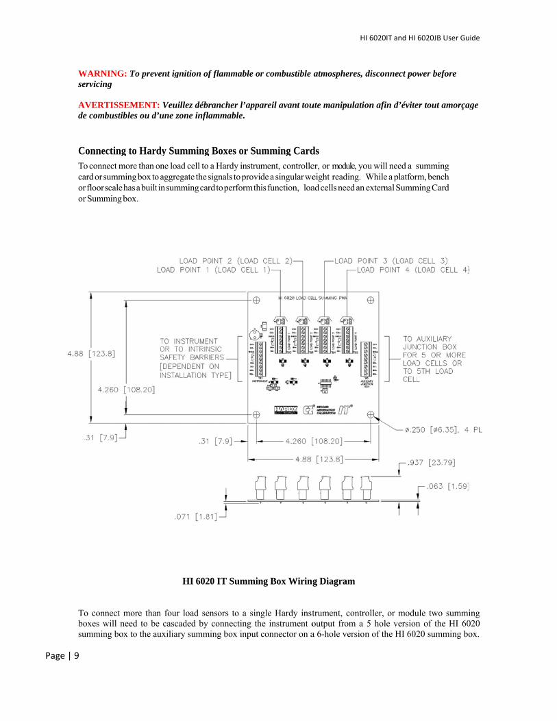
ConneTo conncard or sor floor or Summ
To conboxes wsummin
NING: To prevng
TISSEMENTbustibles ou d
ecting to Harnect more than osumming box toscale has a builtming box.
nnect more thawill need to beng box to the a
vent ignition of
T: Veuillez débrd’une zone infl
dy Summingone load cell too aggregate the st in summing car
HI 602
an four load see cascaded by
auxiliary summ
f flammable or
rancher l’appalammable.
g Boxes or Su a Hardy instrumsignals to provird to perform th
20 IT Summin
ensors to a sinconnecting th
ming box input
r combustible
areil avant tou
umming Cardment, controllede a singular weis function, loa
ng Box Wiring
gle Hardy insthe instrument oconnector on a
H
atmospheres,
ute manipulatio
ds er, or module, yoeight reading.ad cells need an
g Diagram
trument, controutput from a a 6-hole version
I 6020IT and HI
disconnect po
on afin d’évite
ou will need a sWhile a platforexternal Summ
roller, or modu5 hole versionn of the HI 602
6020JB User Gu
wer before
er tout amorça
summing rm, bench ming Card
ule two summin of the HI 6020 summing bo
uide
age
ing 020 ox.
HI 6020IT and HI 6020JB User Guide
Page | 10
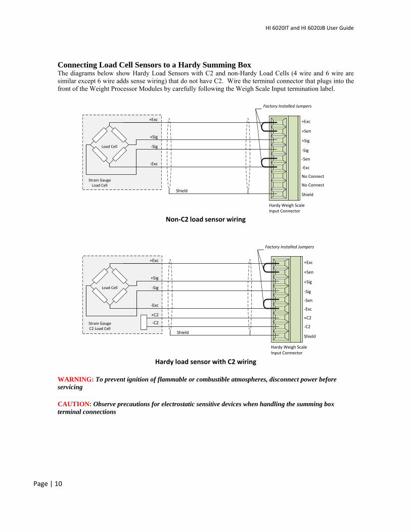
Connecting Load Cell Sensors to a Hardy Summing Box The diagrams below show Hardy Load Sensors with C2 and non-Hardy Load Cells (4 wire and 6 wire are similar except 6 wire adds sense wiring) that do not have C2. Wire the terminal connector that plugs into the front of the Weight Processor Modules by carefully following the Weigh Scale Input termination label.
Non‐C2 load sensor wiring
Hardy load sensor with C2 wiring
WARNING: To prevent ignition of flammable or combustible atmospheres, disconnect power before servicing CAUTION: Observe precautions for electrostatic sensitive devices when handling the summing box terminal connections
Strain GaugeLoad Cell
Load Cell
Shield
-Exc
+Exc
No Connect
-Sig
+Sig
Shield
+Sen
-Sen
No Connect
-Exc
+Exc
-Sig
+Sig
Factory Installed Jumpers
Hardy Weigh ScaleInput Connector
Load Cell
Shield
-Exc
+Exc
-Sig
+Sig
Shield
+Sen
-Sen-Exc
+Exc
-Sig
+Sig
Factory Installed Jumpers
Hardy Weigh ScaleInput Connector
+C2
-C2Strain GaugeC2 Load Cell
+C2
-C2
HI 6020IT and HI 6020JB User Guide
Page | 11
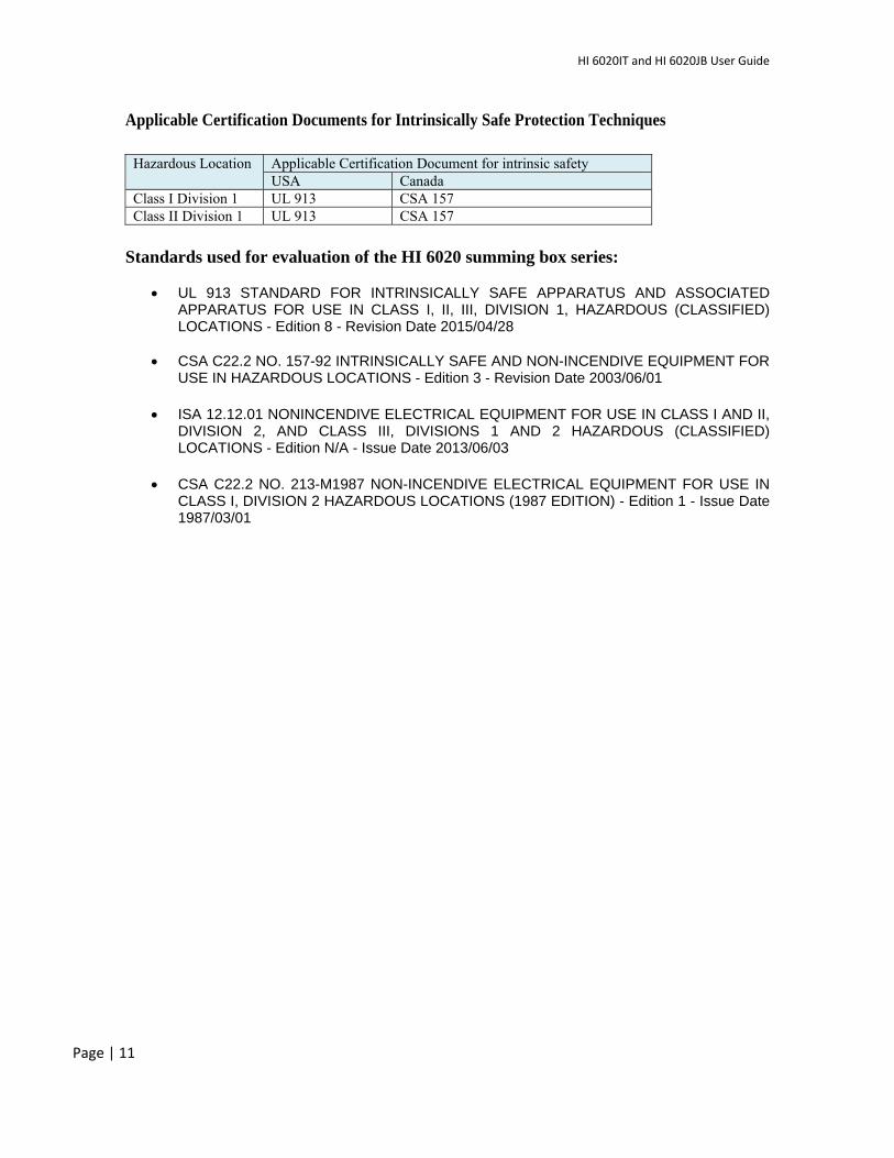
Applicable Certification Documents for Intrinsically Safe Protection Techniques
Hazardous Location Applicable Certification Document for intrinsic safety
USA Canada Class I Division 1 UL 913 CSA 157 Class II Division 1 UL 913 CSA 157
Standards used for evaluation of the HI 6020 summing box series:
UL 913 STANDARD FOR INTRINSICALLY SAFE APPARATUS AND ASSOCIATED APPARATUS FOR USE IN CLASS I, II, III, DIVISION 1, HAZARDOUS (CLASSIFIED) LOCATIONS - Edition 8 - Revision Date 2015/04/28
CSA C22.2 NO. 157-92 INTRINSICALLY SAFE AND NON-INCENDIVE EQUIPMENT FOR
USE IN HAZARDOUS LOCATIONS - Edition 3 - Revision Date 2003/06/01
ISA 12.12.01 NONINCENDIVE ELECTRICAL EQUIPMENT FOR USE IN CLASS I AND II, DIVISION 2, AND CLASS III, DIVISIONS 1 AND 2 HAZARDOUS (CLASSIFIED) LOCATIONS - Edition N/A - Issue Date 2013/06/03
CSA C22.2 NO. 213-M1987 NON-INCENDIVE ELECTRICAL EQUIPMENT FOR USE IN
CLASS I, DIVISION 2 HAZARDOUS LOCATIONS (1987 EDITION) - Edition 1 - Issue Date 1987/03/01

HI 6020IT and HI 6020JB User Guide
Page | 12
This page intentionally left blank
Pa age | 13
At Hard
We beli
That’s w
Want M
dy, we believe
ieve that sim
why our solut
MORE PRODU
Har© Cop
e that indust
mplicity delive
tions are EAS
UCTIVITY at th
9440 CarTelephonWeb Ad
rdy Process Sopyright 2014-
rial weighing
ers the LOWE
SIER to install
he LEAST TOT
rroll Park Dne: 1-800-821ddress: http:/
olutions Docu2015, Hardy P
Printed
g solutions sh
ST TOTAL CO
l, integrate, c
TAL COST to o
rive, San Die-5831 FAX:
//www.hardy
ment NumberProcess Soluti
d in the U.S.A.
H
hould be EASY
OST to own.
commission, d
own? Call Ha
ego, CA 9212(858) 278-67
ysolutions.com
r: 0596-0352-0ions, All Right
.
I 6020IT and HI
Y to engineer
diagnose and
rdy to discov
21 700 m
01 REV A ts Reserved.
6020JB User Gu
r and operate
d maintain.
ver how Toda
uide
e.
ay!