Embed Size (px)
Citation preview
1/2
Ref. Certif. No.
US-31640-UL
IEC SYSTEM FOR MUTUAL RECOGNITION OF TEST CERTIFICATES FOR ELECTRICAL EQUIPMENT (IECEE) CB SCHEME
CB TEST CERTIFICATE
Product
DC-DC Converter
Name and address of the applicant
Cosel Co., Ltd. 1-6-43 Kamiakae-machi, Toyama-shi, Toyama 930-0816, Japan
Name and address of the manufacturer
Cosel Co., Ltd. 1-6-43 Kamiakae-machi, Toyama-shi, Toyama 930-0816, Japan
Name and address of the factory Note: When more than one factory, please report on page 2
Cosel Co., Ltd. 1-6-43 Kamiakae-machi Toyama-shi, Toyama 930-0816, Japan
Additional Information on page 2
Ratings and principal characteristics Trademark (if any)
36 - 76 Vdc, maximum 20.5 A
Type of Customer’s Testing Facility (CTF) Stage used
Model / Type Ref.
CHS70048y, See Page 2
Additional information (if necessary may also be reported on page 2)
Additionally evaluated to EN 62368-1:2014. National Differences specified in the CB Test Report.
Additional Information on page 2 A sample of the product was tested and found to be in conformity with
IEC 62368-1(ed.2)
As shown in the Test Report Ref. No. which forms part of this Certificate
4788264268 issued on 2018-04-23
This CB Test Certificate is issued by the National Certification Body
UL (US), 333 Pfingsten Rd IL 60062, Northbrook, USA
UL (Demko), Borupvang 5A DK-2750 Ballerup, DENMARK
UL (JP), Marunouchi Trust Tower Main Building 6F, 1-8-3 Marunouchi, Chiyoda-ku, Tokyo 100-0005, JAPAN
UL (CA), 7 Underwriters Road, Toronto, M1R 3B4 Ontario, CANADA For full legal entity names see www.ul.com/ncbnames
Date: 2018-04-25
Signature: Jolanta M. Wroblewska
2/2
Ref. Certif. No.
US-31640-UL
Model Details:
CHS70048y y is 12H
May be followed by suffix -z#####
(z is B or blank, # is any number 0 to 9 or letter A to Z)
Factories:
Cosel Co., Ltd. Tateyama Factory
78 Dogenji, Tateyama Machi Nakaniikawa-gun, Toyama 930-0241,
Japan
Eikoku Co., Ltd.
45-6 Nishida Kaneoke, Kokufu-cho Takayama-shi, Gifu 509-4123,
Japan
Eikoku Co., Ltd. Toyama Satellite Factory
223 Nakajinzu Yatsuo-Machi, Toyama-shi, Toyama 939-2311,
Japan
Daiyon Corp.
1-18 Zoushima, Fuchu-machi, Toyama-shi, Toyama-ken 939-2726,
Japan
Kyousei Co., Ltd.
501-1 Nakaookubo Toyama-shi, Toyama-Ken 939-2243,
Japan
Takanami Co., Ltd.
2000-39 Hirokami Imizu-shi, Toyama-Ken 939-0256,
Japan
Sunrise Industries Co., Ltd.
2-24-6 Terajima, Itoigawa-shi, Niigata 941-0066,
Japan
Wuxi Cosel Electronics Co., Ltd.
5TH FL, BLD A3, No.866 Liyuan Development Zone Wuxi, Jiangsu 214072
China
Glanzhokuriku Co., Ltd.
476 Hashizume machi Hakusan City 924-0812
Japan
Futaba Dies Co., Ltd.
762-1Kunugiyama Nyuzen-machi Shimo Niikawa-Gun Toyama-ken 936-0627
Japan
Additional information (if necessary)
UL (US), 333 Pfingsten Rd IL 60062, Northbrook, USA
UL (Demko), Borupvang 5A DK-2750 Ballerup, DENMARK
UL (JP), Marunouchi Trust Tower Main Building 6F, 1-8-3 Marunouchi, Chiyoda-ku, Tokyo 100-0005, JAPAN
UL (CA), 7 Underwriters Road, Toronto, M1R 3B4 Ontario, CANADA For full legal entity names see www.ul.com/ncbnames
Signature: Jolanta M. Wroblewska
Date: 2018-04-25
Test Report issued under the responsibility of:
TEST REPORT
IEC 62368-1
Audio/video, information and communication technology equipment
Part 1: Safety requirements
Report Number ............................. : 4788264268
Date of issue .................................. : 2018-04-23
Total number of pages ................... : 64
Applicant’s name ......................... : Cosel Co., Ltd.
Address ......................................... : 1-6-43 Kamiakae-machi, Toyama-shi, Toyama 930-0816, Japan
Test specification:
Standard ....................................... : IEC 62368-1:2014 (Second Edition)
Test procedure .............................. : CB Scheme
Non-standard test method ............. : N/A
Test Report Form No. ................. : IEC62368_1B
Test Report Form(s) Originator...... : UL(US)
Master TRF ................................... : 2014-03
Copyright © 2014 Worldwide System for Conformity Testing and Certification of Electrotechnical Equipment and Components (IECEE), Geneva, Switzerland. All rights reserved.
This publication may be reproduced in whole or in part for non-commercial purposes as long as the IECEE is acknowledged as copyright owner and source of the material. IECEE takes no responsibility for and will not assume liability for damages resulting from the reader's interpretation of the reproduced material due to its placement and context.
If this Test Report Form is used by non-IECEE members, the IECEE/IEC logo and the reference to the CB Scheme procedure shall be removed.
This report is not valid as a CB Test Report unless signed by an approved CB Testing Laboratory and appended to a CB Test Certificate issued by an NCB in accordance with IECEE 02.
General disclaimer:
The test results presented in this report relate only to the object tested. This report shall not be reproduced, except in full, without the written approval of the Issuing CB Testing Laboratory. The authenticity of this Test Report and its contents can be verified by contacting the NCB, responsible for this Test Report.

Page 2 of 64 Report No. 4788264268
IEC62368_1B
Test Item description .................................. : DC-DC Converter
Trade Mark ................................................. :
Manufacturer ............................................... : Same as applicant
Model/Type reference ................................. : CHS70048y, y is 12H
May be followed by suffix -z#####
(z is B or blank, # is any number 0 to 9 or letter A to Z)
Ratings ....................................................... : 36 - 76 Vdc, maximum 20.5 A
Page 3 of 64 Report No. 4788264268
IEC62368_1B
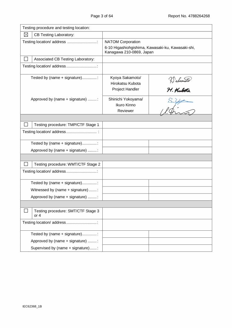
Testing procedure and testing location:
CB Testing Laboratory:
Testing location/ address .......................... : NATOM Corporation
6-10 Higashiohgishima, Kawasaki-ku, Kawasaki-shi, Kanagawa 210-0869, Japan
Associated CB Testing Laboratory:
Testing location/ address ........................... :
Tested by (name + signature) ............. : Kyoya Sakamoto/
Hirokatsu Kubota
Project Handler
Approved by (name + signature) ........ : Shinichi Yokoyama/
Ikuro Kinno
Reviewer
Testing procedure: TMP/CTF Stage 1
Testing location/ address ........................... :
Tested by (name + signature) ............. :
Approved by (name + signature) ........ :
Testing procedure: WMT/CTF Stage 2
Testing location/ address ........................... :
Tested by (name + signature) ............. :
Witnessed by (name + signature) ....... :
Approved by (name + signature) ........ :
Testing procedure: SMT/CTF Stage 3 or 4
Testing location/ address ........................... :
Tested by (name + signature) ............. :
Approved by (name + signature) ........ :
Supervised by (name + signature) ...... :

Page 4 of 64 Report No. 4788264268
IEC62368_1B
List of Attachments (including a total number of pages in each attachment):
- European Group Differences and National Differences (3 pages)
- Denmark National Differences (2 pages)
- Canada and U.S.A. National Differences (6 pages)
- Enclosures (19 pages)
Summary of testing:
Unless otherwise indicated, all tests were conducted at NATOM Corporation, 6-10 Higashiohgishima, Kawasaki-ku, Kawasaki-shi, Kanagawa, 210-0869 Japan.
Tests performed (name of test and test clause):
- Classification of electrical energy sources (5.2)
- Test for hygroscopic materials (5.4.1.3)
- Temperature measurements (5.4.1.4, 6.3.2, 9.0, B.2.6)
- Determination of working voltage (5.4.1.8)
- Minimum Clearances/Creepage distance (5.4.2.2, 5.4.2.4, 5.4.3)
- Minimum Clearances distances using required withstand voltage (5.4.2.3)
- Tests for semiconductor components and cemented joints (5.4.7, 5.4.1.5.3 (5.4.4.4, 5.4.4.5))
- Electric strength tests (5.4.9)
- Electrical power sources (PS) measurements for classification (6.2.2)
- Input test (B.2.5)
- Abnormal operating condition tests (B.3)
- Fault condition tests (B.4)
Testing location:
Tests for semiconductor components and cemented joints (5.4.7, 5.4.1.5.3 (5.4.4.4, 5.4.4.5)): was subcontracted to qualified CBTL UL Japan, Inc. that has the standard in scope.
Summary of compliance with National Differences:
List of countries addressed
Summary of compliance with National Differences (for explanation of codes see below):
Group differences and CA, DK, FI, GB, IT, NO, SE and US.
CA=Canada, DK=Denmark, FI: Finland, GB=United Kingdom, IT=Italy, NO=Norway, SE=Sweden and US=United States of America.
Group Differences of CENELEC according to the above-mentioned standard and Group Differences are applicable for CENELEC member countries: Austria, Belgium, Bulgaria, Croatia, Cyprus, the Czech Republic, Denmark, Estonia, Finland, Former Yugoslav Republic of Macedonia, France, Germany, Greece, Hungary, Iceland, Ireland, Italy, Latvia, Lithuania, Luxembourg, Malta, the Netherlands, Norway, Poland, Portugal, Romania, Slovakia, Slovenia, Spain, Sweden, Switzerland, Turkey and the United Kingdom.
For National Differences see end of this report.
Additionally evaluated Test specifications.
EN 62368-1:2014 Audio/video, information and communication technology equipment Part 1: Safety requirements.
UL 62368-1:2014 Audio/video, information and communication technology equipment – Part 1: Safety requirements.
CSA C22.2 NO. 62368-1-14 Audio/video, information and communication technology equipment – Part 1: Safety requirements.
The product fulfils the requirements of IEC 62368-1:2014 (Second Edition).
Page 5 of 64 Report No. 4788264268
IEC62368_1B
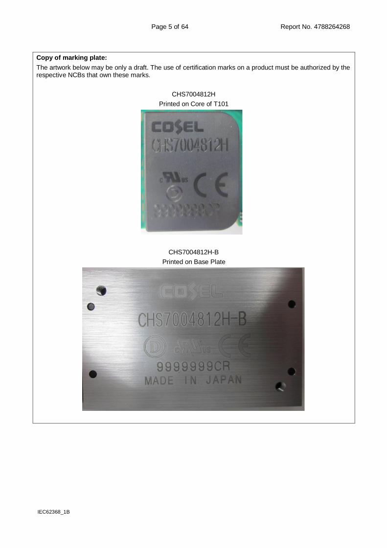
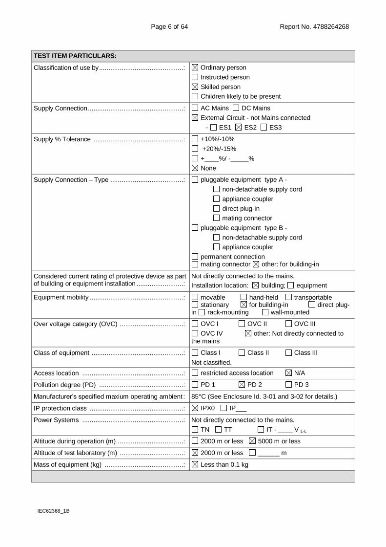
Copy of marking plate:
The artwork below may be only a draft. The use of certification marks on a product must be authorized by the respective NCBs that own these marks.
CHS7004812H
Printed on Core of T101
CHS7004812H-B
Printed on Base Plate
Page 6 of 64 Report No. 4788264268
IEC62368_1B
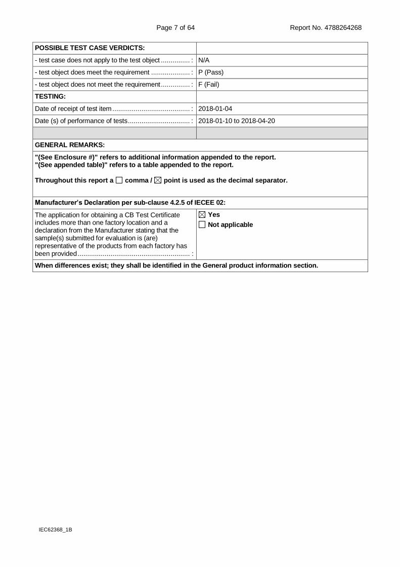
TEST ITEM PARTICULARS:
Classification of use by .............................................: Ordinary person
Instructed person
Skilled person
Children likely to be present
Supply Connection ...................................................: AC Mains DC Mains
External Circuit - not Mains connected
- ES1 ES2 ES3
Supply % Tolerance ................................................: +10%/-10%
+20%/-15%
+____%/ -_____%
None
Supply Connection – Type .......................................: pluggable equipment type A -
non-detachable supply cord
appliance coupler
direct plug-in
mating connector
pluggable equipment type B -
non-detachable supply cord
appliance coupler
permanent connection mating connector other: for building-in
Considered current rating of protective device as part of building or equipment installation .........................:
Not directly connected to the mains.
Installation location: building; equipment
Equipment mobility ..................................................: movable hand-held transportable stationary for building-in direct plug-
in rack-mounting wall-mounted
Over voltage category (OVC) ..................................: OVC I OVC II OVC III
OVC IV other: Not directly connected to the mains
Class of equipment .................................................: Class I Class II Class III
Not classified.
Access location ......................................................: restricted access location N/A
Pollution degree (PD) .............................................: PD 1 PD 2 PD 3
Manufacturer’s specified maxium operating ambient : 85°C (See Enclosure Id. 3-01 and 3-02 for details.)
IP protection class ..................................................: IPX0 IP___
Power Systems ......................................................: Not directly connected to the mains.
TN TT IT - ____ V L-L
Altitude during operation (m) ...................................: 2000 m or less 5000 m or less
Altitude of test laboratory (m) ..................................: 2000 m or less ______ m
Mass of equipment (kg) ..........................................: Less than 0.1 kg
Page 7 of 64 Report No. 4788264268
IEC62368_1B
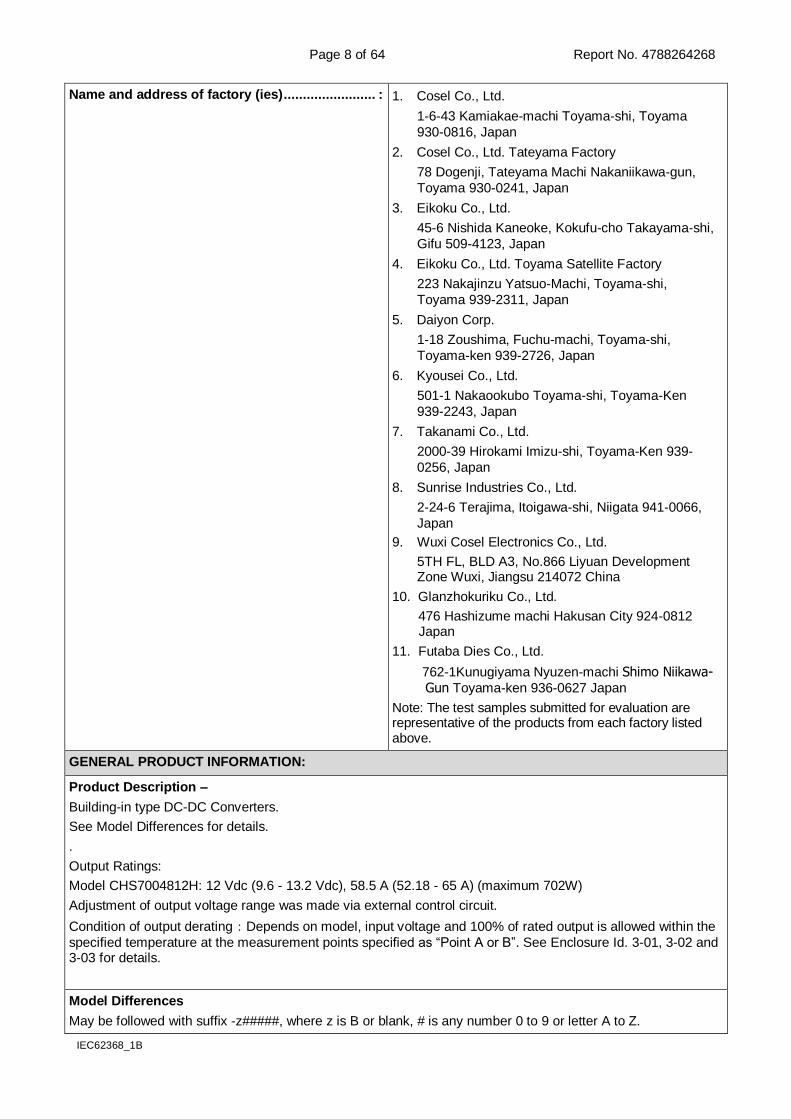
POSSIBLE TEST CASE VERDICTS:
- test case does not apply to the test object ............... : N/A
- test object does meet the requirement .................... : P (Pass)
- test object does not meet the requirement ............... : F (Fail)
TESTING:
Date of receipt of test item ........................................ : 2018-01-04
Date (s) of performance of tests ................................ : 2018-01-10 to 2018-04-20
GENERAL REMARKS:
"(See Enclosure #)" refers to additional information appended to the report. "(See appended table)" refers to a table appended to the report. Throughout this report a comma / point is used as the decimal separator.
Manufacturer’s Declaration per sub-clause 4.2.5 of IECEE 02:
The application for obtaining a CB Test Certificate includes more than one factory location and a declaration from the Manufacturer stating that the sample(s) submitted for evaluation is (are) representative of the products from each factory has been provided .......................................................... :
Yes
Not applicable
When differences exist; they shall be identified in the General product information section.
Page 8 of 64 Report No. 4788264268
IEC62368_1B
Name and address of factory (ies) ........................ : 1. Cosel Co., Ltd.
1-6-43 Kamiakae-machi Toyama-shi, Toyama
930-0816, Japan
2. Cosel Co., Ltd. Tateyama Factory
78 Dogenji, Tateyama Machi Nakaniikawa-gun,
Toyama 930-0241, Japan
3. Eikoku Co., Ltd.
45-6 Nishida Kaneoke, Kokufu-cho Takayama-shi,
Gifu 509-4123, Japan
4. Eikoku Co., Ltd. Toyama Satellite Factory
223 Nakajinzu Yatsuo-Machi, Toyama-shi,
Toyama 939-2311, Japan
5. Daiyon Corp.
1-18 Zoushima, Fuchu-machi, Toyama-shi,
Toyama-ken 939-2726, Japan
6. Kyousei Co., Ltd.
501-1 Nakaookubo Toyama-shi, Toyama-Ken
939-2243, Japan
7. Takanami Co., Ltd.
2000-39 Hirokami Imizu-shi, Toyama-Ken 939-
0256, Japan
8. Sunrise Industries Co., Ltd.
2-24-6 Terajima, Itoigawa-shi, Niigata 941-0066,
Japan
9. Wuxi Cosel Electronics Co., Ltd.
5TH FL, BLD A3, No.866 Liyuan Development Zone Wuxi, Jiangsu 214072 China
10. Glanzhokuriku Co., Ltd.
476 Hashizume machi Hakusan City 924-0812 Japan
11. Futaba Dies Co., Ltd.
762-1Kunugiyama Nyuzen-machi Shimo Niikawa-Gun Toyama-ken 936-0627 Japan
Note: The test samples submitted for evaluation are representative of the products from each factory listed above.
GENERAL PRODUCT INFORMATION:
Product Description –
Building-in type DC-DC Converters.
See Model Differences for details.
.
Output Ratings:
Model CHS7004812H: 12 Vdc (9.6 - 13.2 Vdc), 58.5 A (52.18 - 65 A) (maximum 702W)
Adjustment of output voltage range was made via external control circuit.
Condition of output derating:Depends on model, input voltage and 100% of rated output is allowed within the
specified temperature at the measurement points specified as “Point A or B”. See Enclosure Id. 3-01, 3-02 and 3-03 for details.
Model Differences
May be followed with suffix -z#####, where z is B or blank, # is any number 0 to 9 or letter A to Z.
Page 9 of 64 Report No. 4788264268
IEC62368_1B
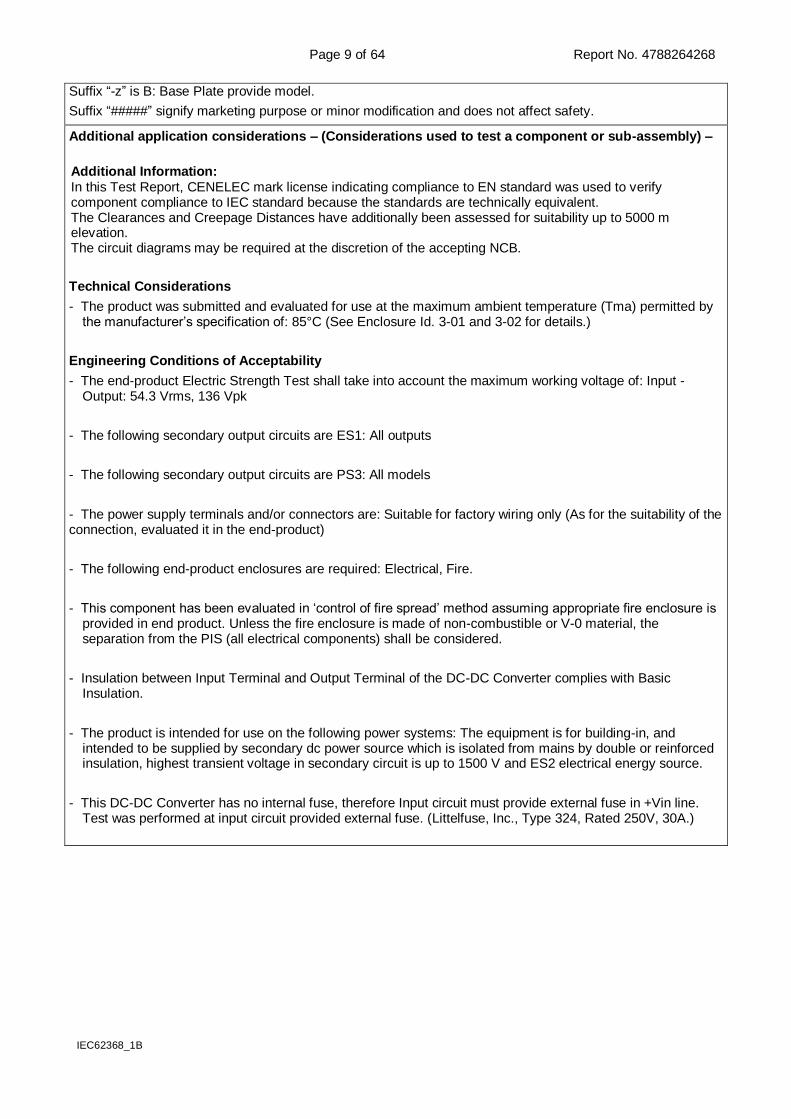
Suffix “-z” is B: Base Plate provide model.
Suffix “#####” signify marketing purpose or minor modification and does not affect safety.
Additional application considerations – (Considerations used to test a component or sub-assembly) –
Additional Information: In this Test Report, CENELEC mark license indicating compliance to EN standard was used to verify component compliance to IEC standard because the standards are technically equivalent. The Clearances and Creepage Distances have additionally been assessed for suitability up to 5000 m elevation. The circuit diagrams may be required at the discretion of the accepting NCB.
Technical Considerations
- The product was submitted and evaluated for use at the maximum ambient temperature (Tma) permitted by the manufacturer’s specification of: 85°C (See Enclosure Id. 3-01 and 3-02 for details.)
Engineering Conditions of Acceptability
- The end-product Electric Strength Test shall take into account the maximum working voltage of: Input - Output: 54.3 Vrms, 136 Vpk
- The following secondary output circuits are ES1: All outputs
- The following secondary output circuits are PS3: All models
- The power supply terminals and/or connectors are: Suitable for factory wiring only (As for the suitability of the connection, evaluated it in the end-product)
- The following end-product enclosures are required: Electrical, Fire.
- This component has been evaluated in ‘control of fire spread’ method assuming appropriate fire enclosure is provided in end product. Unless the fire enclosure is made of non-combustible or V-0 material, the separation from the PIS (all electrical components) shall be considered.
- Insulation between Input Terminal and Output Terminal of the DC-DC Converter complies with Basic Insulation.
- The product is intended for use on the following power systems: The equipment is for building-in, and intended to be supplied by secondary dc power source which is isolated from mains by double or reinforced insulation, highest transient voltage in secondary circuit is up to 1500 V and ES2 electrical energy source.
- This DC-DC Converter has no internal fuse, therefore Input circuit must provide external fuse in +Vin line. Test was performed at input circuit provided external fuse. (Littelfuse, Inc., Type 324, Rated 250V, 30A.)
Page 10 of 64 Report No. 4788264268
IEC62368_1B
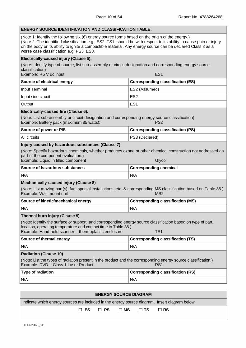
ENERGY SOURCE IDENTIFICATION AND CLASSIFICATION TABLE:
(Note 1: Identify the following six (6) energy source forms based on the origin of the energy.) (Note 2: The identified classification e.g., ES2, TS1, should be with respect to its ability to cause pain or injury on the body or its ability to ignite a combustible material. Any energy source can be declared Class 3 as a worse case classification e.g. PS3, ES3.
Electrically-caused injury (Clause 5):
(Note: Identify type of source, list sub-assembly or circuit designation and corresponding energy source classification) Example: +5 V dc input ES1
Source of electrical energy Corresponding classification (ES)
Input Terminal ES2 (Assumed)
Input side circuit ES2
Output ES1
Electrically-caused fire (Clause 6):
(Note: List sub-assembly or circuit designation and corresponding energy source classification) Example: Battery pack (maximum 85 watts): PS2
Source of power or PIS Corresponding classification (PS)
All circuits PS3 (Declared)
Injury caused by hazardous substances (Clause 7)
(Note: Specify hazardous chemicals, whether produces ozone or other chemical construction not addressed as part of the component evaluation.) Example: Liquid in filled component Glycol
Source of hazardous substances Corresponding chemical
N/A N/A
Mechanically-caused injury (Clause 8)
(Note: List moving part(s), fan, special installations, etc. & corresponding MS classification based on Table 35.) Example: Wall mount unit MS2
Source of kinetic/mechanical energy Corresponding classification (MS)
N/A N/A
Thermal burn injury (Clause 9)
(Note: Identify the surface or support, and corresponding energy source classification based on type of part, location, operating temperature and contact time in Table 38.) Example: Hand-held scanner – thermoplastic enclosure TS1
Source of thermal energy Corresponding classification (TS)
N/A N/A
Radiation (Clause 10)
(Note: List the types of radiation present in the product and the corresponding energy source classification.) Example: DVD – Class 1 Laser Product RS1
Type of radiation Corresponding classification (RS)
N/A N/A
ENERGY SOURCE DIAGRAM
Indicate which energy sources are included in the energy source diagram. Insert diagram below
ES PS MS TS RS
Page 11 of 64 Report No. 4788264268
IEC62368_1B
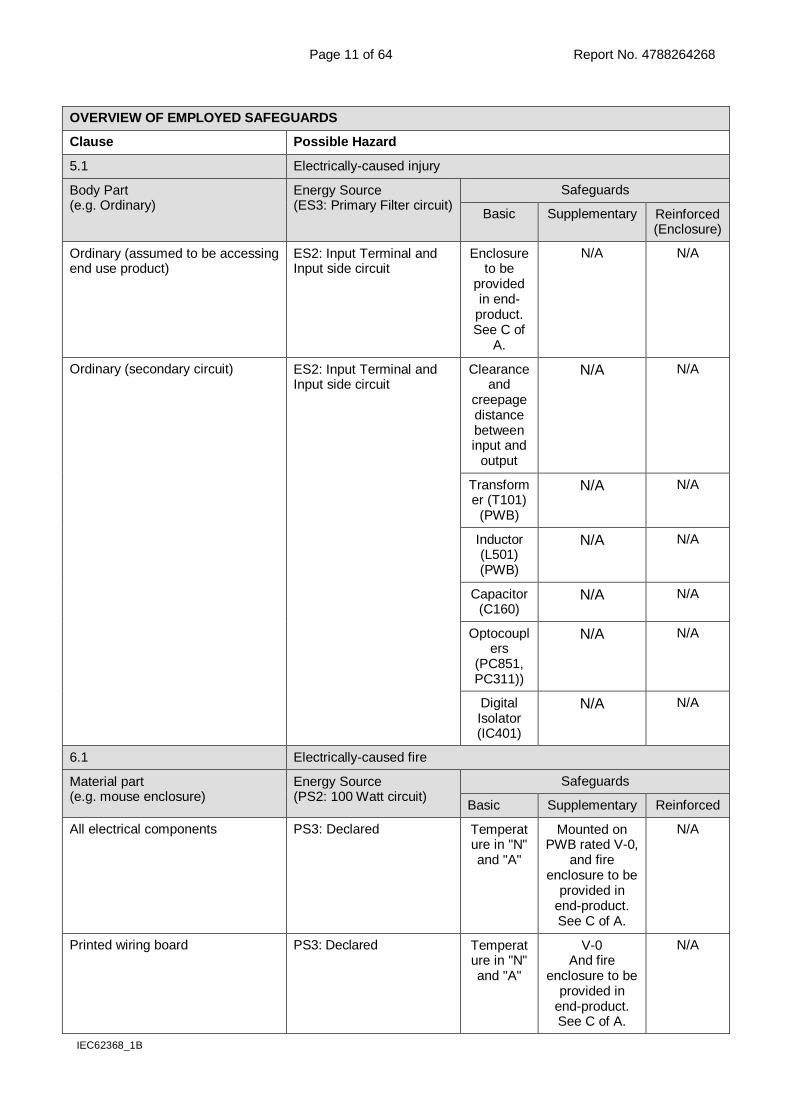
OVERVIEW OF EMPLOYED SAFEGUARDS
Clause Possible Hazard
5.1 Electrically-caused injury
Body Part (e.g. Ordinary)
Energy Source (ES3: Primary Filter circuit)
Safeguards
Basic Supplementary Reinforced (Enclosure)
Ordinary (assumed to be accessing end use product)
ES2: Input Terminal and Input side circuit
Enclosure to be
provided in end-
product. See C of
A.
N/A N/A
Ordinary (secondary circuit) ES2: Input Terminal and Input side circuit
Clearance and
creepage distance between input and
output
N/A N/A
Transformer (T101)
(PWB)
N/A N/A
Inductor (L501) (PWB)
N/A N/A
Capacitor (C160)
N/A N/A
Optocouplers
(PC851, PC311))
N/A N/A
Digital Isolator (IC401)
N/A N/A
6.1 Electrically-caused fire
Material part (e.g. mouse enclosure)
Energy Source (PS2: 100 Watt circuit)
Safeguards
Basic Supplementary Reinforced
All electrical components PS3: Declared Temperature in "N" and "A"
Mounted on PWB rated V-0,
and fire enclosure to be
provided in end-product. See C of A.
N/A
Printed wiring board PS3: Declared Temperature in "N" and "A"
V-0 And fire
enclosure to be provided in
end-product. See C of A.
N/A
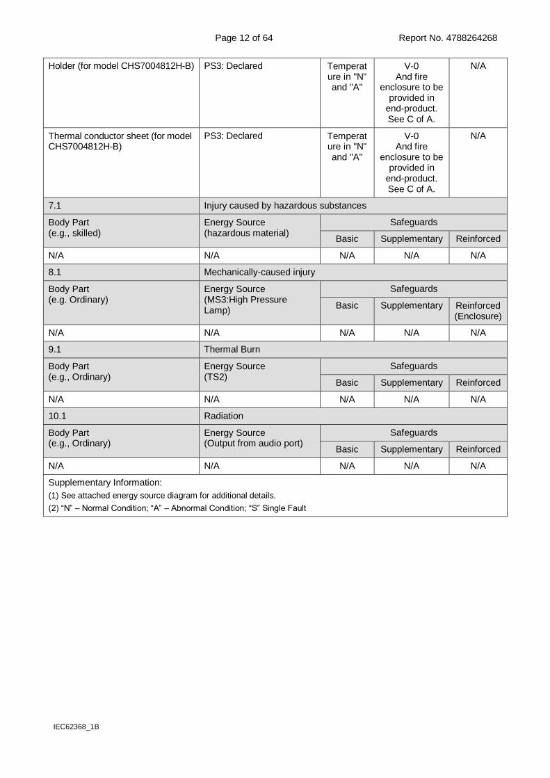
Page 12 of 64 Report No. 4788264268
IEC62368_1B
Holder (for model CHS7004812H-B) PS3: Declared Temperature in "N" and "A"
V-0 And fire
enclosure to be provided in
end-product. See C of A.
N/A
Thermal conductor sheet (for model CHS7004812H-B)
PS3: Declared Temperature in "N" and "A"
V-0 And fire
enclosure to be provided in
end-product. See C of A.
N/A
7.1 Injury caused by hazardous substances
Body Part (e.g., skilled)
Energy Source (hazardous material)
Safeguards
Basic Supplementary Reinforced
N/A N/A N/A N/A N/A
8.1 Mechanically-caused injury
Body Part (e.g. Ordinary)
Energy Source (MS3:High Pressure Lamp)
Safeguards
Basic Supplementary Reinforced (Enclosure)
N/A N/A N/A N/A N/A
9.1 Thermal Burn
Body Part (e.g., Ordinary)
Energy Source (TS2)
Safeguards
Basic Supplementary Reinforced
N/A N/A N/A N/A N/A
10.1 Radiation
Body Part (e.g., Ordinary)
Energy Source (Output from audio port)
Safeguards
Basic Supplementary Reinforced
N/A N/A N/A N/A N/A
Supplementary Information:
(1) See attached energy source diagram for additional details.
(2) “N” – Normal Condition; “A” – Abnormal Condition; “S” Single Fault
Page 13 of 64 Report No. 4788264268
IEC 62368-1
Clause Requirement + Test Result - Remark Verdict
IEC62368_1B
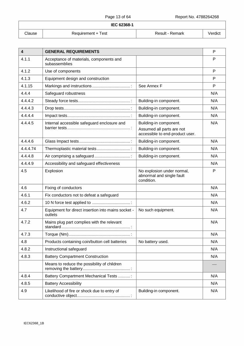
4 GENERAL REQUIREMENTS P
4.1.1 Acceptance of materials, components and subassemblies
P
4.1.2 Use of components P
4.1.3 Equipment design and construction P
4.1.15 Markings and instructions ................................ : See Annex F P
4.4.4 Safeguard robustness N/A
4.4.4.2 Steady force tests ............................................ : Building-in component. N/A
4.4.4.3 Drop tests ........................................................ : Building-in component. N/A
4.4.4.4 Impact tests ..................................................... : Building-in component. N/A
4.4.4.5 Internal accessible safeguard enclosure and barrier tests ..................................................... :
Building-in component.
Assumed all parts are not accessible to end-product user.
N/A
4.4.4.6 Glass Impact tests ........................................... : Building-in component. N/A
4.4.4.74 Thermoplastic material tests ............................ : Building-in component. N/A
4.4.4.8 Air comprising a safeguard .............................. : Building-in component. N/A
4.4.4.9 Accessibility and safeguard effectiveness N/A
4.5 Explosion No explosion under normal, abnormal and single fault condition.
P
4.6 Fixing of conductors N/A
4.6.1 Fix conductors not to defeat a safeguard N/A
4.6.2 10 N force test applied to ................................ : N/A
4.7 Equipment for direct insertion into mains socket - outlets
No such equipment. N/A
4.7.2 Mains plug part complies with the relevant standard .......................................................... :
N/A
4.7.3 Torque (Nm) .................................................... : N/A
4.8 Products containing coin/button cell batteries No battery used. N/A
4.8.2 Instructional safeguard N/A
4.8.3 Battery Compartment Construction N/A
Means to reduce the possibility of children removing the battery ........................................ :
4.8.4 Battery Compartment Mechanical Tests .......... : N/A
4.8.5 Battery Accessibility N/A
4.9 Likelihood of fire or shock due to entry of conductive object ............................................. :
Building-in component. N/A
Page 14 of 64 Report No. 4788264268
IEC 62368-1
Clause Requirement + Test Result - Remark Verdict
IEC62368_1B
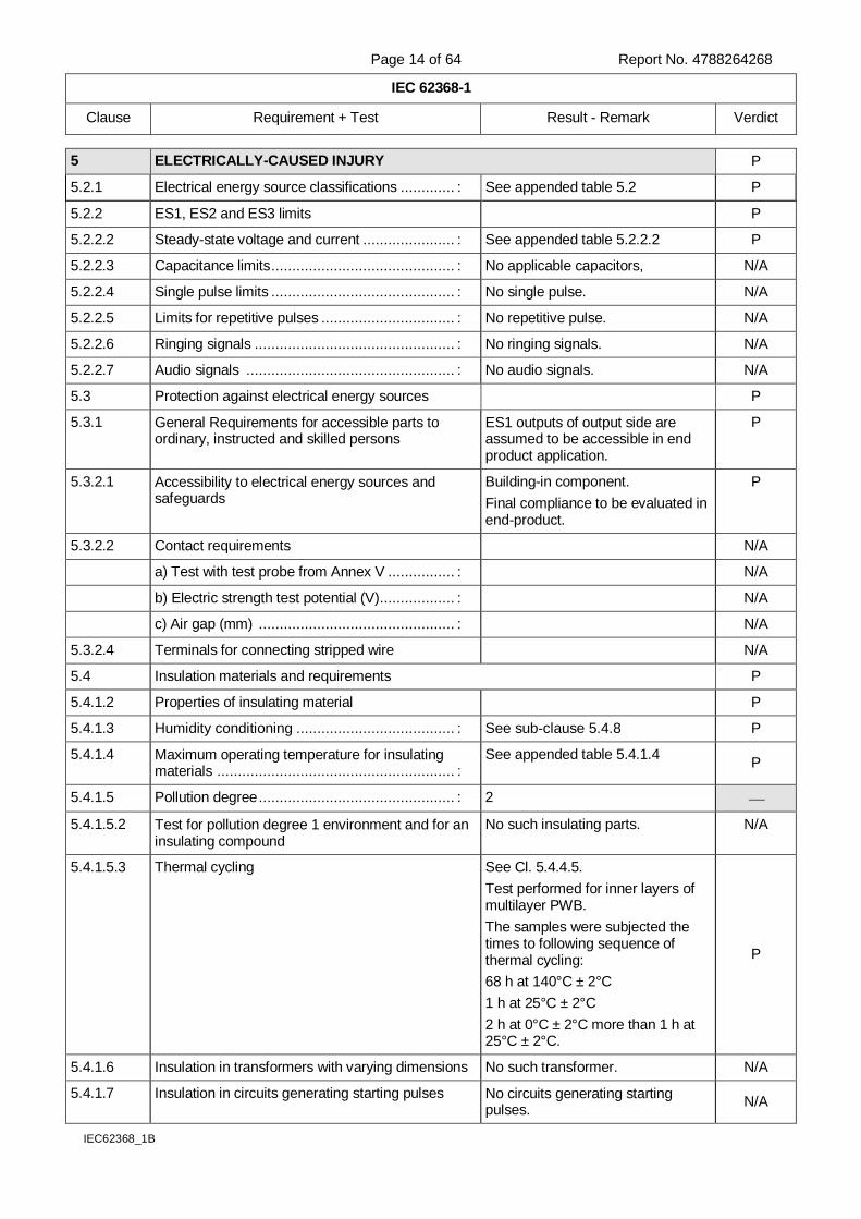
5 ELECTRICALLY-CAUSED INJURY P
5.2.1 Electrical energy source classifications ............. : See appended table 5.2 P
5.2.2 ES1, ES2 and ES3 limits P
5.2.2.2 Steady-state voltage and current ...................... : See appended table 5.2.2.2 P
5.2.2.3 Capacitance limits ............................................ : No applicable capacitors, N/A
5.2.2.4 Single pulse limits ............................................ : No single pulse. N/A
5.2.2.5 Limits for repetitive pulses ................................ : No repetitive pulse. N/A
5.2.2.6 Ringing signals ................................................ : No ringing signals. N/A
5.2.2.7 Audio signals .................................................. : No audio signals. N/A
5.3 Protection against electrical energy sources P
5.3.1 General Requirements for accessible parts to ordinary, instructed and skilled persons
ES1 outputs of output side are assumed to be accessible in end product application.
P
5.3.2.1 Accessibility to electrical energy sources and safeguards
Building-in component.
Final compliance to be evaluated in end-product.
P
5.3.2.2 Contact requirements N/A
a) Test with test probe from Annex V ................ : N/A
b) Electric strength test potential (V) .................. : N/A
c) Air gap (mm) ............................................... : N/A
5.3.2.4 Terminals for connecting stripped wire N/A
5.4 Insulation materials and requirements P
5.4.1.2 Properties of insulating material P
5.4.1.3 Humidity conditioning ...................................... : See sub-clause 5.4.8 P
5.4.1.4 Maximum operating temperature for insulating materials ......................................................... :
See appended table 5.4.1.4 P
5.4.1.5 Pollution degree ............................................... : 2
5.4.1.5.2 Test for pollution degree 1 environment and for an insulating compound
No such insulating parts. N/A
5.4.1.5.3 Thermal cycling See Cl. 5.4.4.5.
Test performed for inner layers of multilayer PWB.
The samples were subjected the times to following sequence of thermal cycling:
68 h at 140°C ± 2°C
1 h at 25°C ± 2°C
2 h at 0°C ± 2°C more than 1 h at 25°C ± 2°C.
P
5.4.1.6 Insulation in transformers with varying dimensions No such transformer. N/A
5.4.1.7 Insulation in circuits generating starting pulses No circuits generating starting pulses.
N/A
Page 15 of 64 Report No. 4788264268
IEC 62368-1
Clause Requirement + Test Result - Remark Verdict
IEC62368_1B
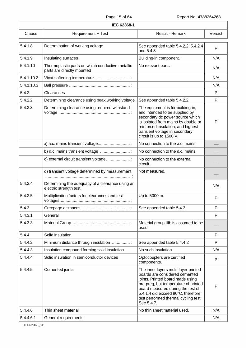
5.4.1.8 Determination of working voltage See appended table 5.4.2.2, 5.4.2.4 and 5.4.3
P
5.4.1.9 Insulating surfaces Building-in component. N/A
5.4.1.10 Thermoplastic parts on which conductive metallic parts are directly mounted
No relevant parts. N/A
5.4.1.10.2 Vicat softening temperature .............................. : N/A
5.4.1.10.3 Ball pressure ................................................... : N/A
5.4.2 Clearances P
5.4.2.2 Determining clearance using peak working voltage See appended table 5.4.2.2 P
5.4.2.3 Determining clearance using required withstand voltage ............................................................ :
The equipment is for building-in, and intended to be supplied by secondary dc power source which is isolated from mains by double or reinforced insulation, and highest transient voltage in secondary circuit is up to 1500 V.
P
a) a.c. mains transient voltage........................... : No connection to the a.c. mains.
b) d.c. mains transient voltage ......................... : No connection to the d.c. mains.
c) external circuit transient voltage .................... : No connection to the external circuit.
d) transient voltage determined by measurement ....................................................................... :
Not measured.
5.4.2.4 Determining the adequacy of a clearance using an electric strength test
N/A
5.4.2.5 Multiplication factors for clearances and test voltages ........................................................... :
Up to 5000 m. P
5.4.3 Creepage distances ......................................... : See appended table 5.4.3 P
5.4.3.1 General P
5.4.3.3 Material Group ................................................ : Material group IIIb is assumed to be used.
5.4.4 Solid insulation P
5.4.4.2 Minimum distance through insulation ............... : See appended table 5.4.4.2 P
5.4.4.3 Insulation compound forming solid insulation No such insulation. N/A
5.4.4.4 Solid insulation in semiconductor devices Optocouplers are certified components.
P
5.4.4.5 Cemented joints The inner layers multi-layer printed boards are considered cemented joints. Printed board made using pre-preg, but temperature of printed board measured during the test of 5.4.1.4 did exceed 90°C, therefore test performed thermal cycling test. See 5.4.7.
P
5.4.4.6 Thin sheet material No thin sheet material used. N/A
5.4.4.6.1 General requirements N/A

Page 16 of 64 Report No. 4788264268
IEC 62368-1
Clause Requirement + Test Result - Remark Verdict
IEC62368_1B
5.4.4.6.2 Separable thin sheet material N/A
Number of layers (pcs) ................................... : N/A
5.4.4.6.3 Non-separable thin sheet material N/A
5.4.4.6.4 Standard test procedure for non-separable thin sheet material .................................................. :
N/A
5.4.4.6.5 Mandrel test N/A
5.4.4.7 Solid insulation in wound components Planar transformer used. See Annex G.13.
N/A
5.4.4.9 Solid insulation at frequencies >30 kHz............ : See appended Table 5.4.4.9 P
5.4.5 Antenna terminal insulation No antenna terminal. N/A
5.4.5.1 General N/A
5.4.5.2 Voltage surge test N/A
Insulation resistance (M) ............................... :
5.4.6 Insulation of internal wire as part of supplementary safeguard ................................ :
No such internal wire. N/A
5.4.7 Tests for semiconductor components and for cemented joints
Tests for between input and output
(Basic Insulation) were performed for inner layers multi-layer printed boards. One of the sample was subjected to the relevant electric strength test, immediately after the last period at 140°C ± 2°C, during thermal cycling. Other two samples were subjected to the relevant electric strength test, after the thermal cycling and humidity conditioning of 5.4.8.
Electric strength test voltage 1500 Vdc (1.6 times 2400 Vdc).
P
5.4.8 Humidity conditioning P
Relative humidity (%) ....................................... : 93
Temperature (°C) ........................................... : 25
Duration (h) .................................................... : 48
5.4.9 Electric strength test ........................................ : See appended table 5.4.9 P
5.4.9.1 Test procedure for a solid insulation type test P
5.4.9.2 Test procedure for routine tests N/A
5.4.10 Protection against transient voltages between external circuit
Building-in component.
No connection to such external circuit.
N/A
5.4.10.1 Parts and circuits separated from external circuits
N/A
5.4.10.2 Test methods N/A
5.4.10.2.1 General N/A
5.4.10.2.2 Impulse test ..................................................... : N/A

Page 17 of 64 Report No. 4788264268
IEC 62368-1
Clause Requirement + Test Result - Remark Verdict
IEC62368_1B
5.4.10.2.3 Steady-state test ............................................. : N/A
5.4.11 Insulation between external circuits and earthed circuitry............................................................ :
Building-in component.
No connection to such external circuit.
N/A
5.4.11.1 Exceptions to separation between external circuits and earth
N/A
5.4.11.2 Requirements N/A
Rated operating voltage Uop (V) ....................... :
Nominal voltage Upeak (V) ................................. :
Max increase due to variation Usp ..................... :
Max increase due to ageing Usa .................... :
Uop= Upeak + Usp + Usa .................................. :
5.5 Components as safeguards
5.5.1 General P
5.5.2 Capacitors and RC units Capacitor C160 used as a basic safeguard between ES2 and ES1.
Application of requirements of Clause G.11 is unnecessary.
P
5.5.2.1 General requirement Working voltage at across the capacitor C160: 4.9 Vpk / 0.3 Vrrms and pass the electric strength test.
See appended table 5.4.9.
P
5.5.2.2 Safeguards against capacitor discharge after disconnection of a connector ........................... :
No such capacitors. N/A
5.5.3 Transformers See Annex G.5.3 P
5.5.4 Optocouplers See sub-clause 5.4.4.4 or Annex G.12
P
5.5.5 Relays Not used. N/A
5.5.6 Resistors No such resistors. N/A
5.5.7 SPD’s Not used. N/A
5.5.7.1 Use of an SPD connected to reliable earthing N/A
5.5.7.2 Use of an SPD between mains and protective earth
N/A
5.5.8 Insulation between the mains and external circuit consisting of a coaxial cable ............................ :
N/A
5.6 Protective conductor N/A
5.6.2 Requirement for protective conductors No protective earthing. N/A
5.6.2.1 General requirements N/A
5.6.2.2 Colour of insulation N/A
5.6.3 Requirement for protective earthing conductors N/A
Protective earthing conductor size (mm2) ........... :
Page 18 of 64 Report No. 4788264268
IEC 62368-1
Clause Requirement + Test Result - Remark Verdict
IEC62368_1B
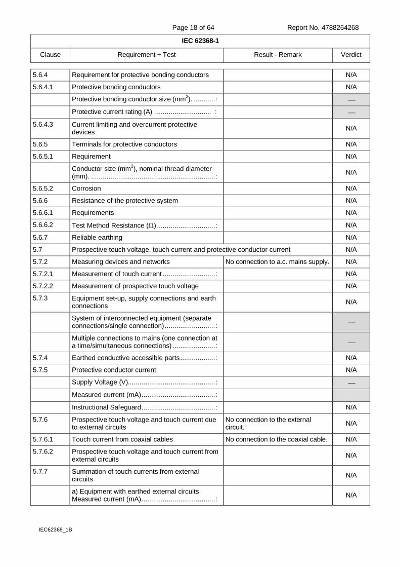
5.6.4 Requirement for protective bonding conductors N/A
5.6.4.1 Protective bonding conductors N/A
Protective bonding conductor size (mm2). ........... :
Protective current rating (A) ............................. :
5.6.4.3 Current limiting and overcurrent protective devices
N/A
5.6.5 Terminals for protective conductors N/A
5.6.5.1 Requirement N/A
Conductor size (mm2), nominal thread diameter
(mm). ................................................................ :
N/A
5.6.5.2 Corrosion N/A
5.6.6 Resistance of the protective system N/A
5.6.6.1 Requirements
N/A
5.6.6.2 Test Method Resistance () .............................. : N/A
5.6.7 Reliable earthing N/A
5.7 Prospective touch voltage, touch current and protective conductor current N/A
5.7.2 Measuring devices and networks No connection to a.c. mains supply. N/A
5.7.2.1 Measurement of touch current ........................... : N/A
5.7.2.2 Measurement of prospective touch voltage N/A
5.7.3 Equipment set-up, supply connections and earth connections
N/A
System of interconnected equipment (separate connections/single connection) .......................... :
Multiple connections to mains (one connection at a time/simultaneous connections) ...................... :
5.7.4 Earthed conductive accessible parts .................. : N/A
5.7.5 Protective conductor current N/A
Supply Voltage (V)............................................. :
Measured current (mA) ...................................... :
Instructional Safeguard ...................................... : N/A
5.7.6 Prospective touch voltage and touch current due to external circuits
No connection to the external circuit.
N/A
5.7.6.1 Touch current from coaxial cables No connection to the coaxial cable. N/A
5.7.6.2 Prospective touch voltage and touch current from external circuits
N/A
5.7.7 Summation of touch currents from external circuits
N/A
a) Equipment with earthed external circuits Measured current (mA) ...................................... :
N/A
Page 19 of 64 Report No. 4788264268
IEC 62368-1
Clause Requirement + Test Result - Remark Verdict
IEC62368_1B
b) Equipment whose external circuits are not referenced to earth. Measured current (mA)....... :
N/A
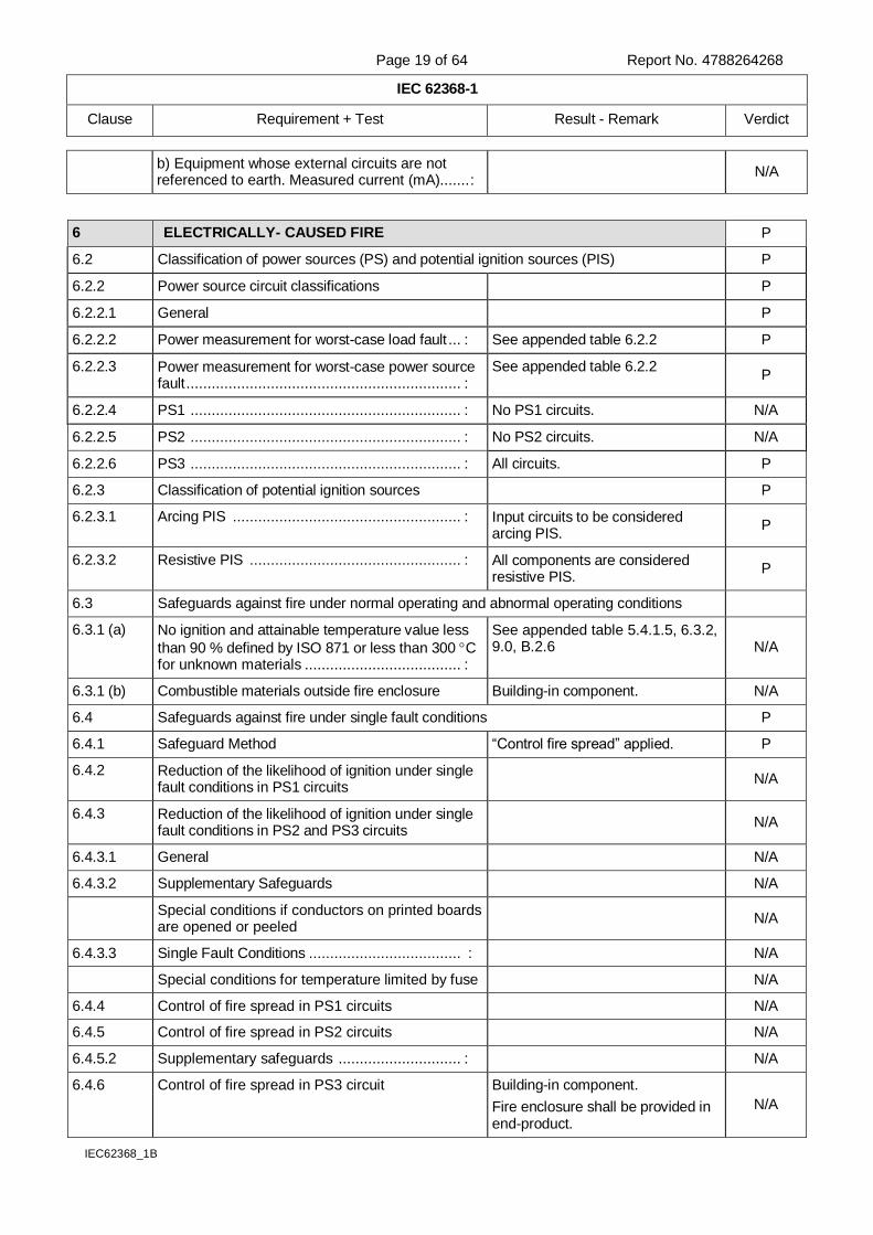
6 ELECTRICALLY- CAUSED FIRE P
6.2 Classification of power sources (PS) and potential ignition sources (PIS) P
6.2.2 Power source circuit classifications P
6.2.2.1 General P
6.2.2.2 Power measurement for worst-case load fault ... : See appended table 6.2.2 P
6.2.2.3 Power measurement for worst-case power source fault ................................................................. :
See appended table 6.2.2 P
6.2.2.4 PS1 ................................................................ : No PS1 circuits. N/A
6.2.2.5 PS2 ................................................................ : No PS2 circuits. N/A
6.2.2.6 PS3 ................................................................ : All circuits. P
6.2.3 Classification of potential ignition sources P
6.2.3.1 Arcing PIS ...................................................... : Input circuits to be considered arcing PIS.
P
6.2.3.2 Resistive PIS .................................................. : All components are considered resistive PIS.
P
6.3 Safeguards against fire under normal operating and abnormal operating conditions
6.3.1 (a) No ignition and attainable temperature value less
than 90 % defined by ISO 871 or less than 300 C for unknown materials ..................................... :
See appended table 5.4.1.5, 6.3.2, 9.0, B.2.6 N/A
6.3.1 (b) Combustible materials outside fire enclosure Building-in component. N/A
6.4 Safeguards against fire under single fault conditions P
6.4.1 Safeguard Method “Control fire spread” applied. P
6.4.2 Reduction of the likelihood of ignition under single fault conditions in PS1 circuits
N/A
6.4.3 Reduction of the likelihood of ignition under single fault conditions in PS2 and PS3 circuits
N/A
6.4.3.1 General N/A
6.4.3.2 Supplementary Safeguards N/A
Special conditions if conductors on printed boards are opened or peeled
N/A
6.4.3.3 Single Fault Conditions .................................... : N/A
Special conditions for temperature limited by fuse N/A
6.4.4 Control of fire spread in PS1 circuits N/A
6.4.5 Control of fire spread in PS2 circuits
N/A
6.4.5.2 Supplementary safeguards ............................. : N/A
6.4.6 Control of fire spread in PS3 circuit Building-in component.
Fire enclosure shall be provided in end-product.
N/A
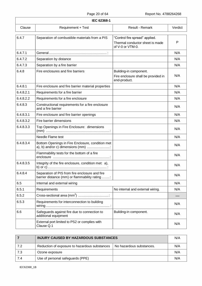
Page 20 of 64 Report No. 4788264268
IEC 62368-1
Clause Requirement + Test Result - Remark Verdict
IEC62368_1B
6.4.7 Separation of combustible materials from a PIS “Control fire spread” applied.
Thermal conductor sheet is made of V-0 or VTM-0.
P
6.4.7.1 General ........................................................... : N/A
6.4.7.2 Separation by distance N/A
6.4.7.3 Separation by a fire barrier N/A
6.4.8 Fire enclosures and fire barriers Building-in component.
Fire enclosure shall be provided in end-product.
N/A
6.4.8.1 Fire enclosure and fire barrier material properties N/A
6.4.8.2.1 Requirements for a fire barrier N/A
6.4.8.2.2 Requirements for a fire enclosure N/A
6.4.8.3 Constructional requirements for a fire enclosure and a fire barrier
N/A
6.4.8.3.1 Fire enclosure and fire barrier openings N/A
6.4.8.3.2 Fire barrier dimensions N/A
6.4.8.3.3 Top Openings in Fire Enclosure: dimensions (mm) ................................................................. :
N/A
Needle Flame test N/A
6.4.8.3.4 Bottom Openings in Fire Enclosure, condition met a), b) and/or c) dimensions (mm) ....................... :
N/A
Flammability tests for the bottom of a fire enclosure .......................................................... :
N/A
6.4.8.3.5 Integrity of the fire enclosure, condition met: a), b) or c) ............................................................ :
N/A
6.4.8.4 Separation of PIS from fire enclosure and fire barrier distance (mm) or flammability rating ........ :
N/A
6.5 Internal and external wiring N/A
6.5.1 Requirements No internal and external wiring. N/A
6.5.2 Cross-sectional area (mm2) ............................... :
6.5.3 Requirements for interconnection to building wiring ................................................................. :
N/A
6.6 Safeguards against fire due to connection to additional equipment
Building-in component. N/A
External port limited to PS2 or complies with Clause Q.1
N/A
7 INJURY CAUSED BY HAZARDOUS SUBSTANCES N/A
7.2 Reduction of exposure to hazardous substances No hazardous substances. N/A
7.3 Ozone exposure N/A
7.4 Use of personal safeguards (PPE) N/A
Page 21 of 64 Report No. 4788264268
IEC 62368-1
Clause Requirement + Test Result - Remark Verdict
IEC62368_1B
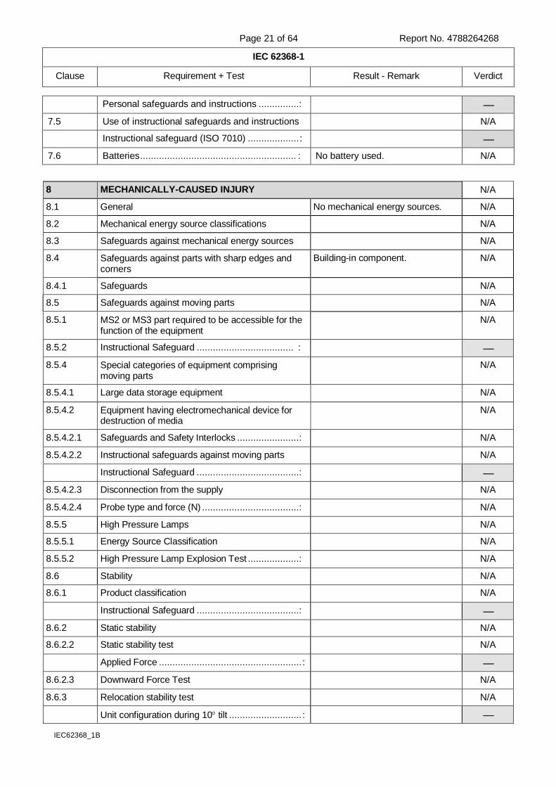
Personal safeguards and instructions ...............:
7.5 Use of instructional safeguards and instructions N/A
Instructional safeguard (ISO 7010) ................... :
7.6 Batteries .......................................................... : No battery used. N/A
8 MECHANICALLY-CAUSED INJURY N/A
8.1 General No mechanical energy sources. N/A
8.2 Mechanical energy source classifications N/A
8.3 Safeguards against mechanical energy sources N/A
8.4 Safeguards against parts with sharp edges and corners
Building-in component. N/A
8.4.1 Safeguards N/A
8.5 Safeguards against moving parts N/A
8.5.1 MS2 or MS3 part required to be accessible for the function of the equipment
N/A
8.5.2 Instructional Safeguard .................................... :
8.5.4 Special categories of equipment comprising moving parts
N/A
8.5.4.1 Large data storage equipment N/A
8.5.4.2 Equipment having electromechanical device for destruction of media
N/A
8.5.4.2.1 Safeguards and Safety Interlocks .......................: N/A
8.5.4.2.2 Instructional safeguards against moving parts N/A
Instructional Safeguard ......................................:
8.5.4.2.3 Disconnection from the supply N/A
8.5.4.2.4 Probe type and force (N) ....................................: N/A
8.5.5 High Pressure Lamps N/A
8.5.5.1 Energy Source Classification N/A
8.5.5.2 High Pressure Lamp Explosion Test ...................: N/A
8.6 Stability N/A
8.6.1 Product classification N/A
Instructional Safeguard ......................................:
8.6.2 Static stability N/A
8.6.2.2 Static stability test N/A
Applied Force ..................................................... :
8.6.2.3 Downward Force Test N/A
8.6.3 Relocation stability test N/A
Unit configuration during 10 tilt ........................... :
Page 22 of 64 Report No. 4788264268
IEC 62368-1
Clause Requirement + Test Result - Remark Verdict
IEC62368_1B
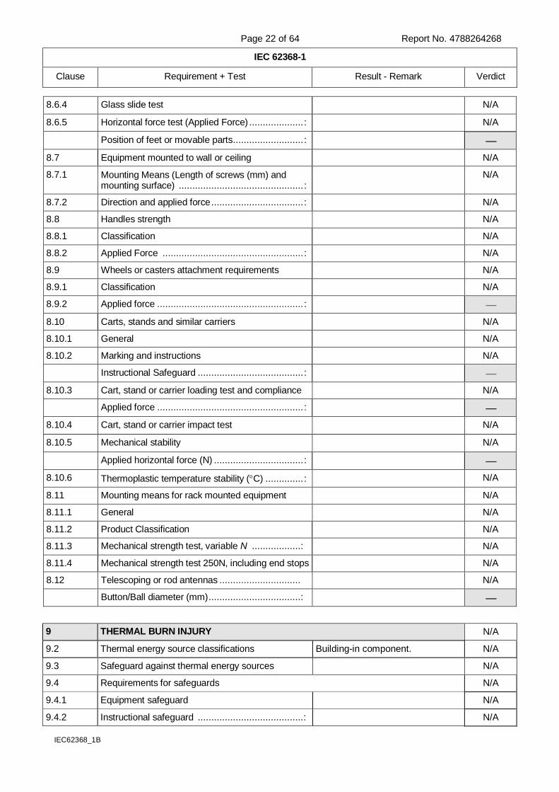
8.6.4 Glass slide test N/A
8.6.5 Horizontal force test (Applied Force) .................... : N/A
Position of feet or movable parts .......................... :
8.7 Equipment mounted to wall or ceiling N/A
8.7.1 Mounting Means (Length of screws (mm) and mounting surface) .............................................. :
N/A
8.7.2 Direction and applied force .................................. : N/A
8.8 Handles strength N/A
8.8.1 Classification N/A
8.8.2 Applied Force .................................................... : N/A
8.9 Wheels or casters attachment requirements N/A
8.9.1 Classification N/A
8.9.2 Applied force ...................................................... :
8.10 Carts, stands and similar carriers N/A
8.10.1 General N/A
8.10.2 Marking and instructions N/A
Instructional Safeguard ....................................... :
8.10.3 Cart, stand or carrier loading test and compliance N/A
Applied force ...................................................... :
8.10.4 Cart, stand or carrier impact test N/A
8.10.5 Mechanical stability N/A
Applied horizontal force (N) ................................. :
8.10.6 Thermoplastic temperature stability (C) .............. : N/A
8.11 Mounting means for rack mounted equipment N/A
8.11.1 General N/A
8.11.2 Product Classification N/A
8.11.3 Mechanical strength test, variable N ..................: N/A
8.11.4 Mechanical strength test 250N, including end stops N/A
8.12 Telescoping or rod antennas .............................. N/A
Button/Ball diameter (mm) ..................................:
9 THERMAL BURN INJURY N/A
9.2 Thermal energy source classifications Building-in component. N/A
9.3 Safeguard against thermal energy sources N/A
9.4 Requirements for safeguards N/A
9.4.1 Equipment safeguard N/A
9.4.2 Instructional safeguard ....................................... : N/A
Page 23 of 64 Report No. 4788264268
IEC 62368-1
Clause Requirement + Test Result - Remark Verdict
IEC62368_1B
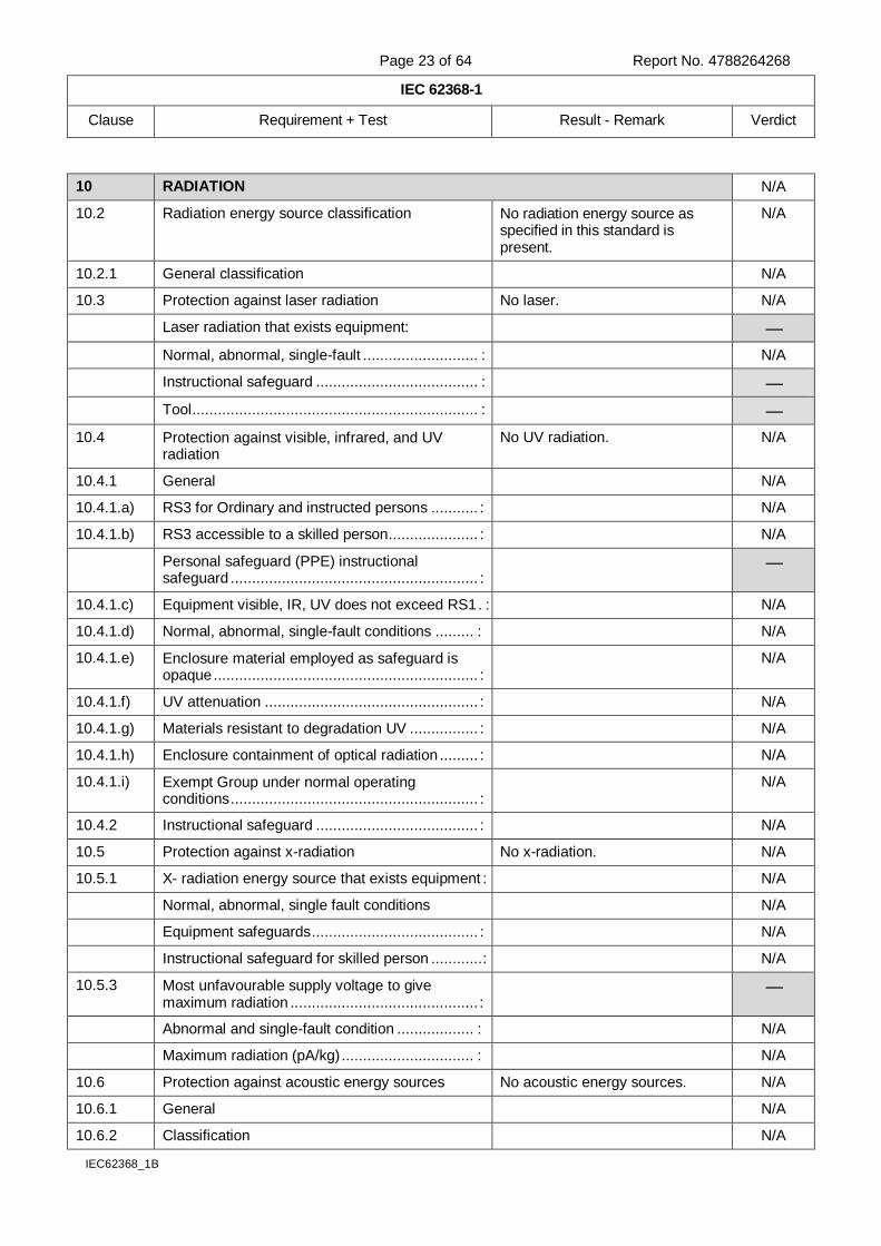
10 RADIATION N/A
10.2 Radiation energy source classification No radiation energy source as specified in this standard is present.
N/A
10.2.1 General classification N/A
10.3 Protection against laser radiation No laser. N/A
Laser radiation that exists equipment:
Normal, abnormal, single-fault ........................... : N/A
Instructional safeguard ...................................... :
Tool ................................................................... :
10.4 Protection against visible, infrared, and UV radiation
No UV radiation. N/A
10.4.1 General N/A
10.4.1.a) RS3 for Ordinary and instructed persons ........... : N/A
10.4.1.b) RS3 accessible to a skilled person ..................... : N/A
Personal safeguard (PPE) instructional safeguard .......................................................... :
10.4.1.c) Equipment visible, IR, UV does not exceed RS1 . : N/A
10.4.1.d) Normal, abnormal, single-fault conditions ......... : N/A
10.4.1.e) Enclosure material employed as safeguard is opaque .............................................................. :
N/A
10.4.1.f) UV attenuation .................................................. : N/A
10.4.1.g) Materials resistant to degradation UV ................ : N/A
10.4.1.h) Enclosure containment of optical radiation ......... : N/A
10.4.1.i) Exempt Group under normal operating conditions .......................................................... :
N/A
10.4.2 Instructional safeguard ...................................... : N/A
10.5 Protection against x-radiation No x-radiation. N/A
10.5.1 X- radiation energy source that exists equipment : N/A
Normal, abnormal, single fault conditions N/A
Equipment safeguards ....................................... : N/A
Instructional safeguard for skilled person ............ : N/A
10.5.3 Most unfavourable supply voltage to give maximum radiation ............................................ :
Abnormal and single-fault condition .................. : N/A
Maximum radiation (pA/kg) ............................... : N/A
10.6 Protection against acoustic energy sources No acoustic energy sources. N/A
10.6.1 General N/A
10.6.2 Classification N/A
Page 24 of 64 Report No. 4788264268
IEC 62368-1
Clause Requirement + Test Result - Remark Verdict
IEC62368_1B
Acoustic output, dB(A) ...................................... : N/A
Output voltage, unweighted r.m.s...................... : N/A
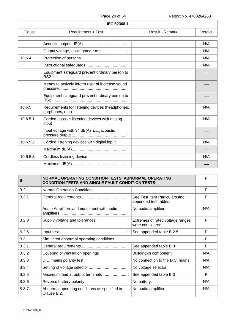
10.6.4 Protection of persons N/A
Instructional safeguards .................................... : N/A
Equipment safeguard prevent ordinary person to RS2 .................................................................. :
Means to actively inform user of increase sound pressure ........................................................... :
Equipment safeguard prevent ordinary person to RS2 .................................................................. :
10.6.5 Requirements for listening devices (headphones, earphones, etc.)
N/A
10.6.5.1 Corded passive listening devices with analog input
N/A
Input voltage with 94 dB(A) LAeq acoustic pressure output ................................................ :
10.6.5.2 Corded listening devices with digital input N/A
Maximum dB(A)................................................ :
10.6.5.3 Cordless listening device N/A
Maximum dB(A)................................................ :
B NORMAL OPERATING CONDITION TESTS, ABNORMAL OPERATING CONDITION TESTS AND SINGLE FAULT CONDITION TESTS
P
B.2 Normal Operating Conditions P
B.2.1 General requirements ........................................ : See Test Item Particulars and appended test tables.
P
Audio Amplifiers and equipment with audio amplifiers .......................................................... :
No audio amplifier. N/A
B.2.3 Supply voltage and tolerances Extremes of rated voltage ranges were considered.
P
B.2.5 Input test ........................................................... : See appended table B.2.5 P
B.3 Simulated abnormal operating conditions P
B.3.1 General requirements ........................................ : See appended table B.3 P
B.3.2 Covering of ventilation openings Building-in component. N/A
B.3.3 D.C. mains polarity test No connection to the D.C. mains. N/A
B.3.4 Setting of voltage selector ................................. : No voltage selector. N/A
B.3.5 Maximum load at output terminals ...................... : See appended table B.3 P
B.3.6 Reverse battery polarity No battery. N/A
B.3.7 Abnormal operating conditions as specified in Clause E.2.
No audio amplifier. N/A

Page 25 of 64 Report No. 4788264268
IEC 62368-1
Clause Requirement + Test Result - Remark Verdict
IEC62368_1B
B.3.8 Safeguards functional during and after abnormal operating conditions
See appended table B.4 P
B.4 Simulated single fault conditions P
B.4.2 Temperature controlling device open or short-circuited ............................................................ :
See appended table B.4 P
B.4.3 Motor tests No motor. N/A
B.4.3.1 Motor blocked or rotor locked increasing the internal ambient temperature ............................ :
N/A
B.4.4 Short circuit of functional insulation See appended table B.4 P
B.4.4.1 Short circuit of clearances for functional insulation See appended table B.4 P
B.4.4.2 Short circuit of creepage distances for functional insulation
See appended table B.4 P
B.4.4.3 Short circuit of functional insulation on coated printed boards
No coated printed board. N/A
B.4.5 Short circuit and interruption of electrodes in tubes and semiconductors
See appended table B.4 P
B.4.6 Short circuit or disconnect of passive components See appended table B.4 P
B.4.7 Continuous operation of components No applicable component. N/A
B.4.8 Class 1 and Class 2 energy sources within limits during and after single fault conditions
See appended table B.4 P
B.4.9 Battery charging under single fault conditions .... : No battery. N/A
C UV RADIATION N/A
C.1 Protection of materials in equipment from UV radiation
No ultraviolet light source. N/A
C.1.2 Requirements N/A
C.1.3 Test method N/A
C.2 UV light conditioning test N/A
C.2.1 Test apparatus N/A
C.2.2 Mounting of test samples N/A
C.2.3 Carbon-arc light-exposure apparatus N/A
C.2.4 Xenon-arc light exposure apparatus N/A
D TEST GENERATORS N/A
D.1 Impulse test generators Not used. N/A
D.2 Antenna interface test generator N/A
D.3 Electronic pulse generator N/A
E TEST CONDITIONS FOR EQUIPMENT CONTAINING AUDIO AMPLIFIERS N/A
E.1 Audio amplifier normal operating conditions No audio amplifier. N/A
Audio signal voltage (V)..................................... :
Rated load impedance (Ω) ................................ :
E.2 Audio amplifier abnormal operating conditions N/A
Page 26 of 64 Report No. 4788264268
IEC 62368-1
Clause Requirement + Test Result - Remark Verdict
IEC62368_1B
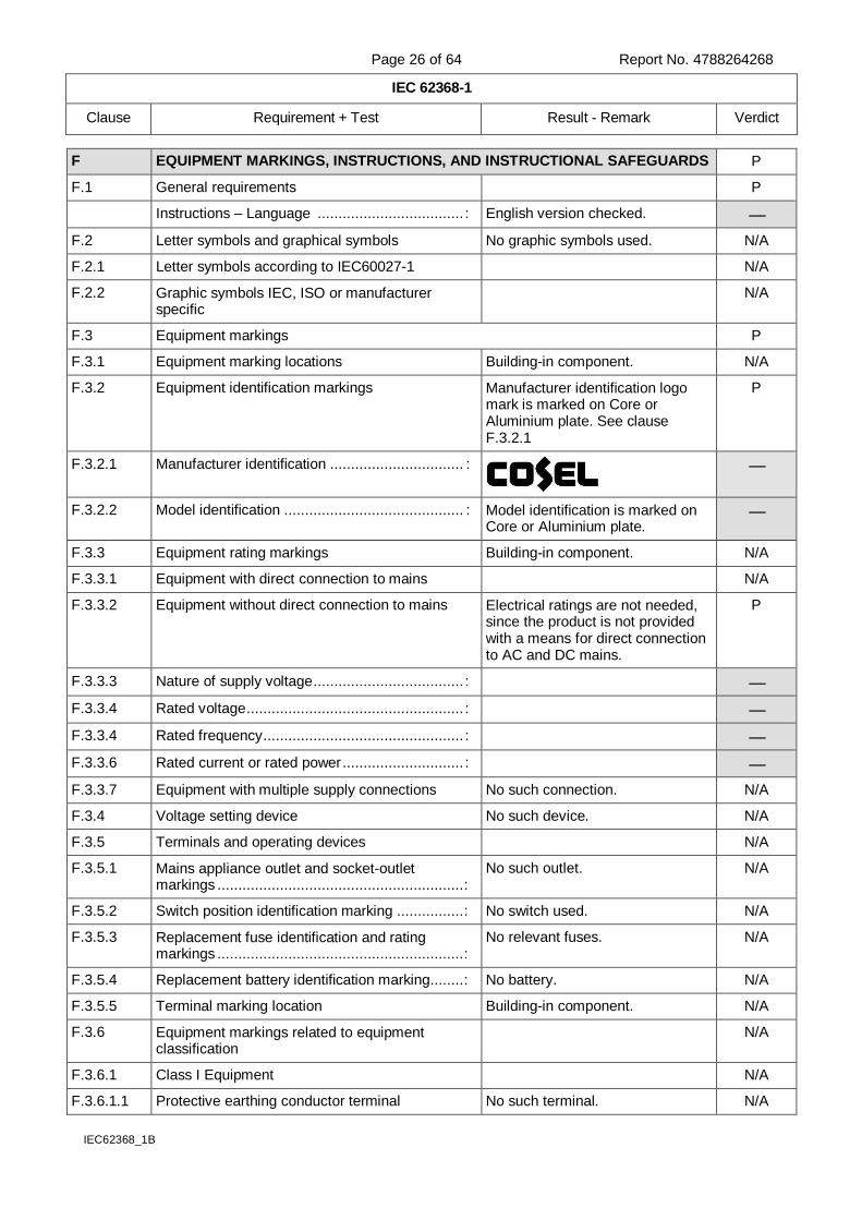
F EQUIPMENT MARKINGS, INSTRUCTIONS, AND INSTRUCTIONAL SAFEGUARDS P
F.1 General requirements P
Instructions – Language ................................... : English version checked.
F.2 Letter symbols and graphical symbols No graphic symbols used. N/A
F.2.1 Letter symbols according to IEC60027-1 N/A
F.2.2 Graphic symbols IEC, ISO or manufacturer specific
N/A
F.3 Equipment markings P
F.3.1 Equipment marking locations Building-in component. N/A
F.3.2 Equipment identification markings Manufacturer identification logo mark is marked on Core or Aluminium plate. See clause F.3.2.1
P
F.3.2.1 Manufacturer identification ................................ :
F.3.2.2 Model identification ........................................... : Model identification is marked on Core or Aluminium plate.
F.3.3 Equipment rating markings Building-in component. N/A
F.3.3.1 Equipment with direct connection to mains N/A
F.3.3.2 Equipment without direct connection to mains Electrical ratings are not needed, since the product is not provided with a means for direct connection to AC and DC mains.
P
F.3.3.3 Nature of supply voltage .................................... :
F.3.3.4 Rated voltage .................................................... :
F.3.3.4 Rated frequency ................................................ :
F.3.3.6 Rated current or rated power ............................. :
F.3.3.7 Equipment with multiple supply connections No such connection. N/A
F.3.4 Voltage setting device No such device. N/A
F.3.5 Terminals and operating devices N/A
F.3.5.1 Mains appliance outlet and socket-outlet markings ........................................................... :
No such outlet. N/A
F.3.5.2 Switch position identification marking ................ : No switch used. N/A
F.3.5.3 Replacement fuse identification and rating markings ........................................................... :
No relevant fuses. N/A
F.3.5.4 Replacement battery identification marking ........ : No battery. N/A
F.3.5.5 Terminal marking location Building-in component. N/A
F.3.6 Equipment markings related to equipment classification
N/A
F.3.6.1 Class I Equipment N/A
F.3.6.1.1 Protective earthing conductor terminal No such terminal. N/A
Page 27 of 64 Report No. 4788264268
IEC 62368-1
Clause Requirement + Test Result - Remark Verdict
IEC62368_1B
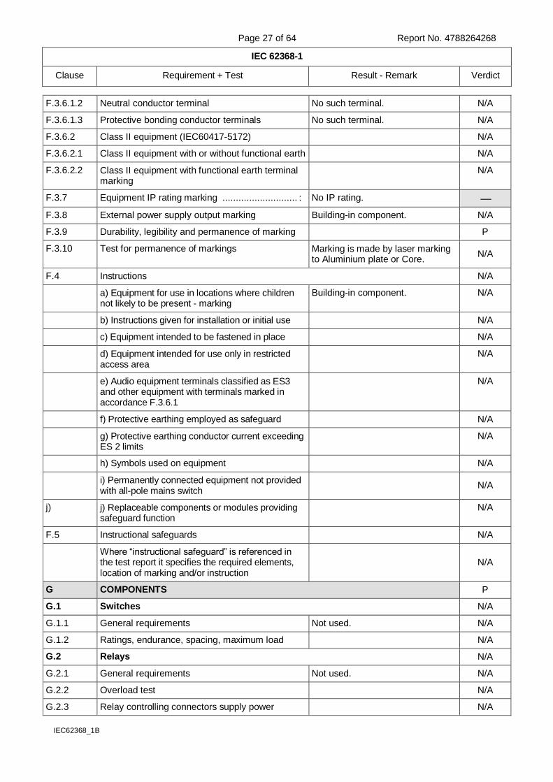
F.3.6.1.2 Neutral conductor terminal No such terminal. N/A
F.3.6.1.3 Protective bonding conductor terminals No such terminal. N/A
F.3.6.2 Class II equipment (IEC60417-5172) N/A
F.3.6.2.1 Class II equipment with or without functional earth N/A
F.3.6.2.2 Class II equipment with functional earth terminal marking
N/A
F.3.7 Equipment IP rating marking ............................ : No IP rating.
F.3.8 External power supply output marking Building-in component. N/A
F.3.9 Durability, legibility and permanence of marking P
F.3.10 Test for permanence of markings Marking is made by laser marking to Aluminium plate or Core.
N/A
F.4 Instructions N/A
a) Equipment for use in locations where children not likely to be present - marking
Building-in component. N/A
b) Instructions given for installation or initial use N/A
c) Equipment intended to be fastened in place N/A
d) Equipment intended for use only in restricted access area
N/A
e) Audio equipment terminals classified as ES3 and other equipment with terminals marked in accordance F.3.6.1
N/A
f) Protective earthing employed as safeguard N/A
g) Protective earthing conductor current exceeding ES 2 limits
N/A
h) Symbols used on equipment N/A
i) Permanently connected equipment not provided with all-pole mains switch
N/A
j) j) Replaceable components or modules providing safeguard function
N/A
F.5 Instructional safeguards N/A
Where “instructional safeguard” is referenced in the test report it specifies the required elements, location of marking and/or instruction
N/A
G COMPONENTS P
G.1 Switches N/A
G.1.1 General requirements Not used. N/A
G.1.2 Ratings, endurance, spacing, maximum load N/A
G.2 Relays N/A
G.2.1 General requirements Not used. N/A
G.2.2 Overload test N/A
G.2.3 Relay controlling connectors supply power N/A
Page 28 of 64 Report No. 4788264268
IEC 62368-1
Clause Requirement + Test Result - Remark Verdict
IEC62368_1B
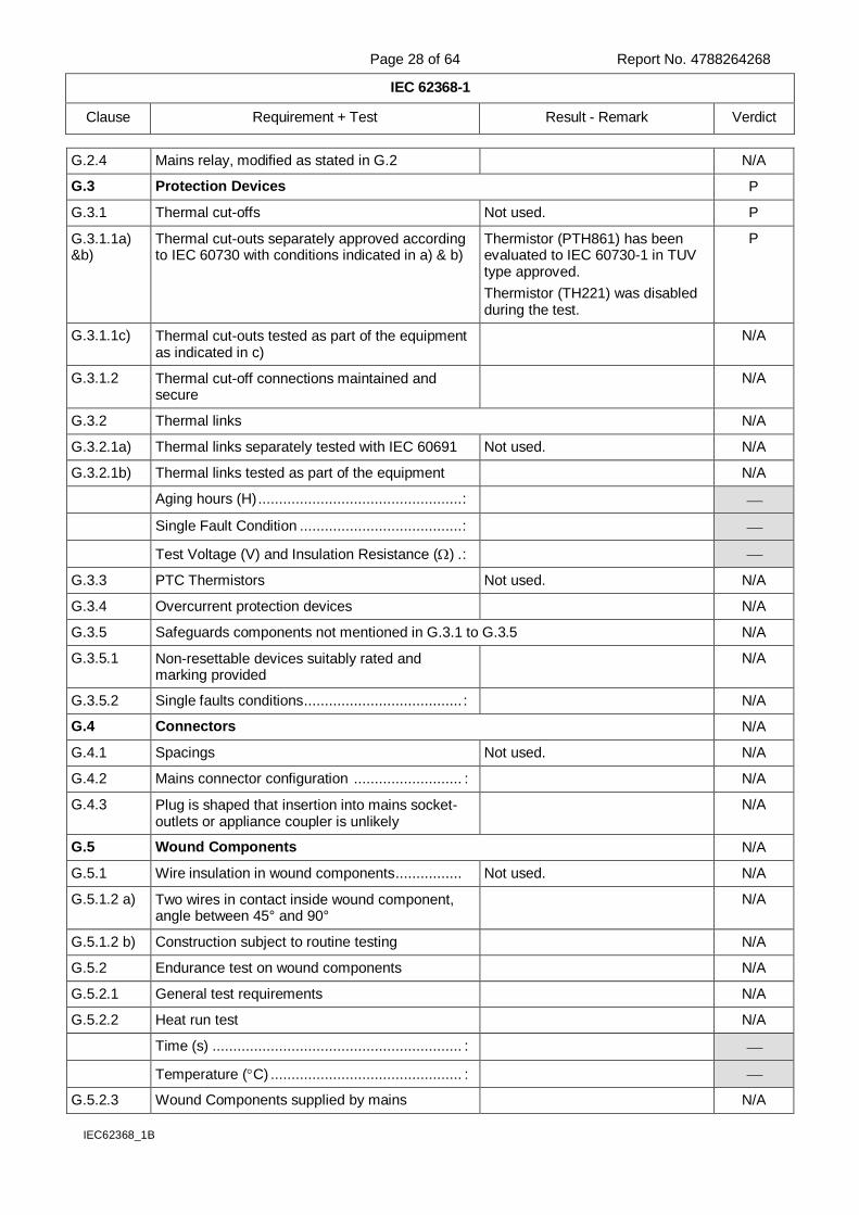
G.2.4 Mains relay, modified as stated in G.2 N/A
G.3 Protection Devices P
G.3.1 Thermal cut-offs Not used. P
G.3.1.1a) &b)
Thermal cut-outs separately approved according to IEC 60730 with conditions indicated in a) & b)
Thermistor (PTH861) has been evaluated to IEC 60730-1 in TUV type approved.
Thermistor (TH221) was disabled during the test.
P
G.3.1.1c) Thermal cut-outs tested as part of the equipment as indicated in c)
N/A
G.3.1.2 Thermal cut-off connections maintained and secure
N/A
G.3.2 Thermal links N/A
G.3.2.1a) Thermal links separately tested with IEC 60691 Not used. N/A
G.3.2.1b) Thermal links tested as part of the equipment N/A
Aging hours (H) ................................................. :
Single Fault Condition ....................................... :
Test Voltage (V) and Insulation Resistance () . :
G.3.3 PTC Thermistors Not used. N/A
G.3.4 Overcurrent protection devices N/A
G.3.5 Safeguards components not mentioned in G.3.1 to G.3.5 N/A
G.3.5.1 Non-resettable devices suitably rated and marking provided
N/A
G.3.5.2 Single faults conditions ...................................... : N/A
G.4 Connectors N/A
G.4.1 Spacings Not used. N/A
G.4.2 Mains connector configuration .......................... : N/A
G.4.3 Plug is shaped that insertion into mains socket-outlets or appliance coupler is unlikely
N/A
G.5 Wound Components N/A
G.5.1 Wire insulation in wound components ................ Not used. N/A
G.5.1.2 a) Two wires in contact inside wound component, angle between 45° and 90°
N/A
G.5.1.2 b) Construction subject to routine testing N/A
G.5.2 Endurance test on wound components N/A
G.5.2.1 General test requirements N/A
G.5.2.2 Heat run test N/A
Time (s) ............................................................ :
Temperature (C) .............................................. :
G.5.2.3 Wound Components supplied by mains N/A
Page 29 of 64 Report No. 4788264268
IEC 62368-1
Clause Requirement + Test Result - Remark Verdict
IEC62368_1B
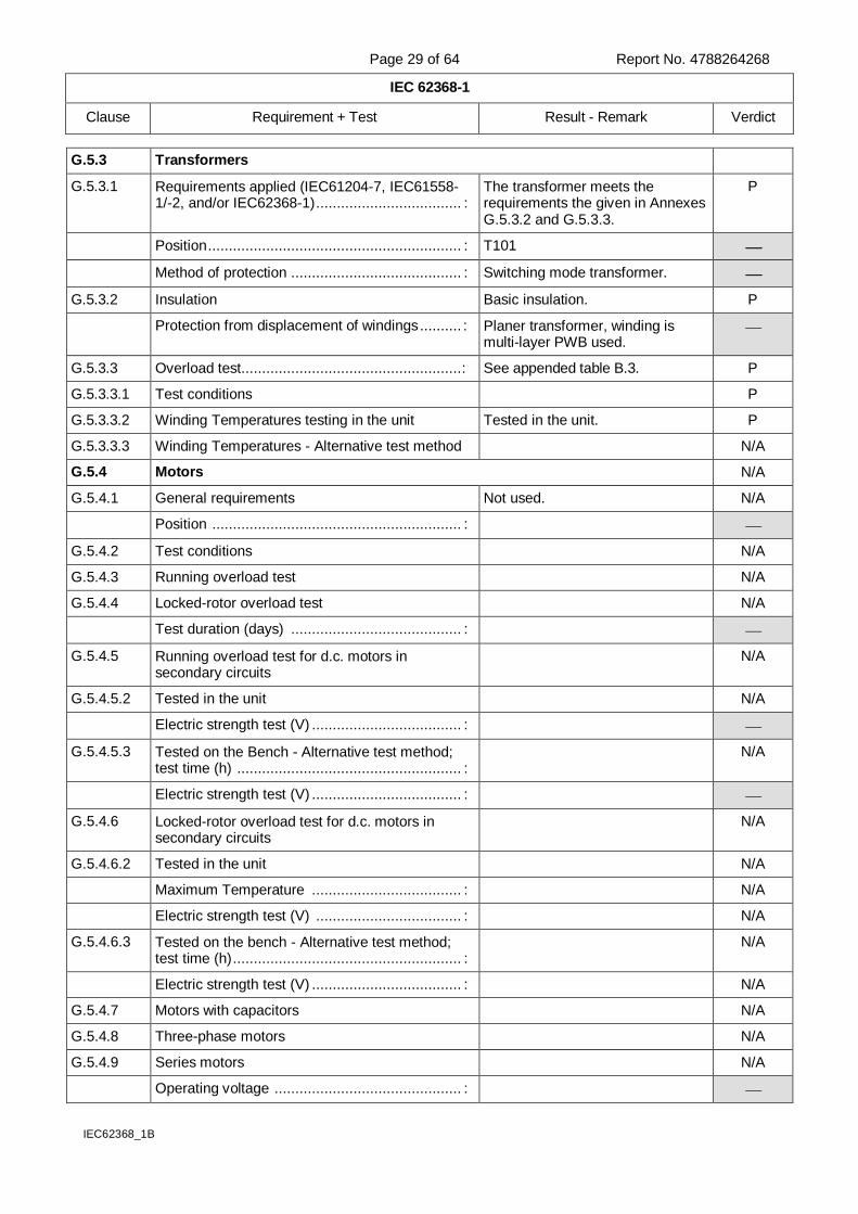
G.5.3 Transformers
G.5.3.1 Requirements applied (IEC61204-7, IEC61558-1/-2, and/or IEC62368-1) ................................... :
The transformer meets the requirements the given in Annexes G.5.3.2 and G.5.3.3.
P
Position ............................................................. : T101
Method of protection ......................................... : Switching mode transformer.
G.5.3.2 Insulation Basic insulation. P
Protection from displacement of windings .......... : Planer transformer, winding is multi-layer PWB used.
G.5.3.3 Overload test..................................................... : See appended table B.3. P
G.5.3.3.1 Test conditions P
G.5.3.3.2 Winding Temperatures testing in the unit Tested in the unit. P
G.5.3.3.3 Winding Temperatures - Alternative test method N/A
G.5.4 Motors N/A
G.5.4.1 General requirements Not used. N/A
Position ............................................................ :
G.5.4.2 Test conditions N/A
G.5.4.3 Running overload test N/A
G.5.4.4 Locked-rotor overload test N/A
Test duration (days) ......................................... :
G.5.4.5 Running overload test for d.c. motors in secondary circuits
N/A
G.5.4.5.2 Tested in the unit N/A
Electric strength test (V) .................................... :
G.5.4.5.3 Tested on the Bench - Alternative test method; test time (h) ...................................................... :
N/A
Electric strength test (V) .................................... :
G.5.4.6 Locked-rotor overload test for d.c. motors in secondary circuits
N/A
G.5.4.6.2 Tested in the unit N/A
Maximum Temperature .................................... : N/A
Electric strength test (V) ................................... : N/A
G.5.4.6.3 Tested on the bench - Alternative test method; test time (h) ....................................................... :
N/A
Electric strength test (V) .................................... : N/A
G.5.4.7 Motors with capacitors N/A
G.5.4.8 Three-phase motors N/A
G.5.4.9 Series motors N/A
Operating voltage ............................................. :
Page 30 of 64 Report No. 4788264268
IEC 62368-1
Clause Requirement + Test Result - Remark Verdict
IEC62368_1B
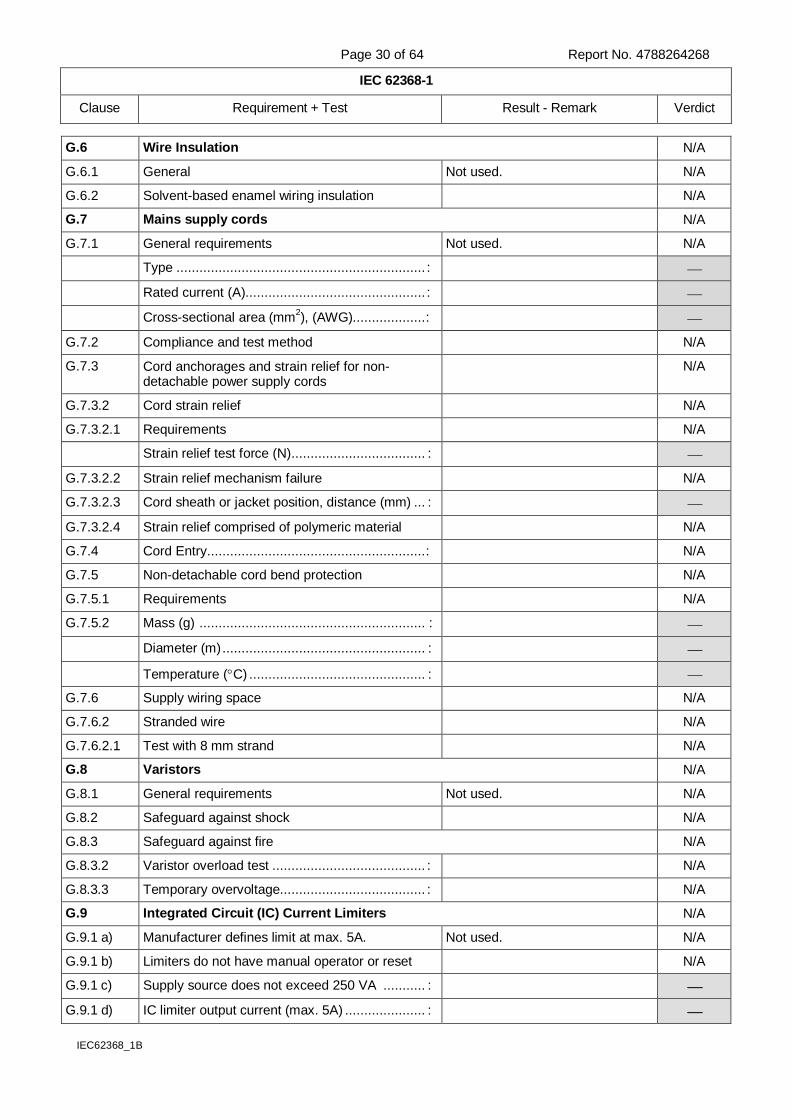
G.6 Wire Insulation N/A
G.6.1 General Not used. N/A
G.6.2 Solvent-based enamel wiring insulation N/A
G.7 Mains supply cords N/A
G.7.1 General requirements Not used. N/A
Type ................................................................. :
Rated current (A)............................................... :
Cross-sectional area (mm2), (AWG)................... :
G.7.2 Compliance and test method N/A
G.7.3 Cord anchorages and strain relief for non-detachable power supply cords
N/A
G.7.3.2 Cord strain relief N/A
G.7.3.2.1 Requirements N/A
Strain relief test force (N) ................................... :
G.7.3.2.2 Strain relief mechanism failure N/A
G.7.3.2.3 Cord sheath or jacket position, distance (mm) ... :
G.7.3.2.4 Strain relief comprised of polymeric material N/A
G.7.4 Cord Entry ......................................................... : N/A
G.7.5 Non-detachable cord bend protection N/A
G.7.5.1 Requirements N/A
G.7.5.2 Mass (g) ........................................................... :
Diameter (m) ..................................................... :
Temperature (C) .............................................. :
G.7.6 Supply wiring space N/A
G.7.6.2 Stranded wire N/A
G.7.6.2.1 Test with 8 mm strand N/A
G.8 Varistors N/A
G.8.1 General requirements Not used. N/A
G.8.2 Safeguard against shock N/A
G.8.3 Safeguard against fire N/A
G.8.3.2 Varistor overload test ........................................ : N/A
G.8.3.3 Temporary overvoltage...................................... : N/A
G.9 Integrated Circuit (IC) Current Limiters N/A
G.9.1 a) Manufacturer defines limit at max. 5A. Not used. N/A
G.9.1 b) Limiters do not have manual operator or reset N/A
G.9.1 c) Supply source does not exceed 250 VA ........... :
G.9.1 d) IC limiter output current (max. 5A) ..................... :
Page 31 of 64 Report No. 4788264268
IEC 62368-1
Clause Requirement + Test Result - Remark Verdict
IEC62368_1B
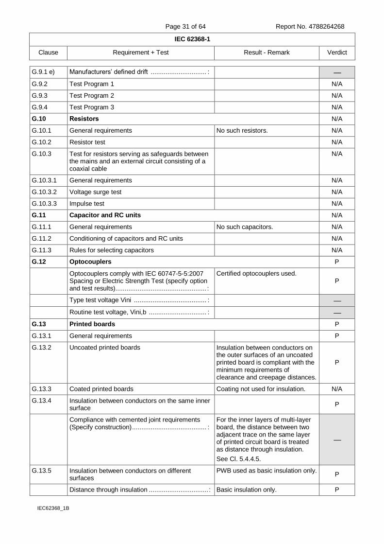
G.9.1 e) Manufacturers’ defined drift .............................. :
G.9.2 Test Program 1 N/A
G.9.3 Test Program 2 N/A
G.9.4 Test Program 3 N/A
G.10 Resistors N/A
G.10.1 General requirements No such resistors. N/A
G.10.2 Resistor test N/A
G.10.3 Test for resistors serving as safeguards between the mains and an external circuit consisting of a coaxial cable
N/A
G.10.3.1 General requirements N/A
G.10.3.2 Voltage surge test N/A
G.10.3.3 Impulse test N/A
G.11 Capacitor and RC units N/A
G.11.1 General requirements No such capacitors. N/A
G.11.2 Conditioning of capacitors and RC units N/A
G.11.3 Rules for selecting capacitors N/A
G.12 Optocouplers P
Optocouplers comply with IEC 60747-5-5:2007 Spacing or Electric Strength Test (specify option and test results)................................................. :
Certified optocouplers used. P
Type test voltage Vini ....................................... :
Routine test voltage, Vini,b ............................... :
G.13 Printed boards P
G.13.1 General requirements P
G.13.2 Uncoated printed boards Insulation between conductors on the outer surfaces of an uncoated printed board is compliant with the minimum requirements of clearance and creepage distances.
P
G.13.3 Coated printed boards Coating not used for insulation. N/A
G.13.4 Insulation between conductors on the same inner surface
P
Compliance with cemented joint requirements (Specify construction) ........................................ :
For the inner layers of multi-layer board, the distance between two adjacent trace on the same layer of printed circuit board is treated as distance through insulation.
See Cl. 5.4.4.5.
G.13.5 Insulation between conductors on different surfaces
PWB used as basic insulation only. P
Distance through insulation ................................ : Basic insulation only. P
Page 32 of 64 Report No. 4788264268
IEC 62368-1
Clause Requirement + Test Result - Remark Verdict
IEC62368_1B
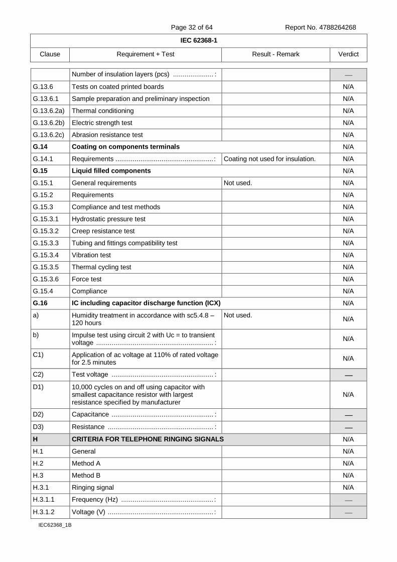
Number of insulation layers (pcs) ..................... :
G.13.6 Tests on coated printed boards N/A
G.13.6.1 Sample preparation and preliminary inspection N/A
G.13.6.2a) Thermal conditioning N/A
G.13.6.2b) Electric strength test N/A
G.13.6.2c) Abrasion resistance test N/A
G.14 Coating on components terminals N/A
G.14.1 Requirements ................................................... : Coating not used for insulation. N/A
G.15 Liquid filled components N/A
G.15.1 General requirements Not used. N/A
G.15.2 Requirements N/A
G.15.3 Compliance and test methods N/A
G.15.3.1 Hydrostatic pressure test N/A
G.15.3.2 Creep resistance test N/A
G.15.3.3 Tubing and fittings compatibility test N/A
G.15.3.4 Vibration test N/A
G.15.3.5 Thermal cycling test N/A
G.15.3.6 Force test N/A
G.15.4 Compliance N/A
G.16 IC including capacitor discharge function (ICX) N/A
a) Humidity treatment in accordance with sc5.4.8 – 120 hours
Not used. N/A
b) Impulse test using circuit 2 with Uc = to transient voltage ............................................................. :
N/A
C1) Application of ac voltage at 110% of rated voltage for 2.5 minutes
N/A
C2) Test voltage ..................................................... :
D1) 10,000 cycles on and off using capacitor with smallest capacitance resistor with largest resistance specified by manufacturer
N/A
D2) Capacitance ..................................................... :
D3) Resistance ....................................................... :
H CRITERIA FOR TELEPHONE RINGING SIGNALS N/A
H.1 General N/A
H.2 Method A N/A
H.3 Method B N/A
H.3.1 Ringing signal N/A
H.3.1.1 Frequency (Hz) ................................................ :
H.3.1.2 Voltage (V) ....................................................... :
Page 33 of 64 Report No. 4788264268
IEC 62368-1
Clause Requirement + Test Result - Remark Verdict
IEC62368_1B
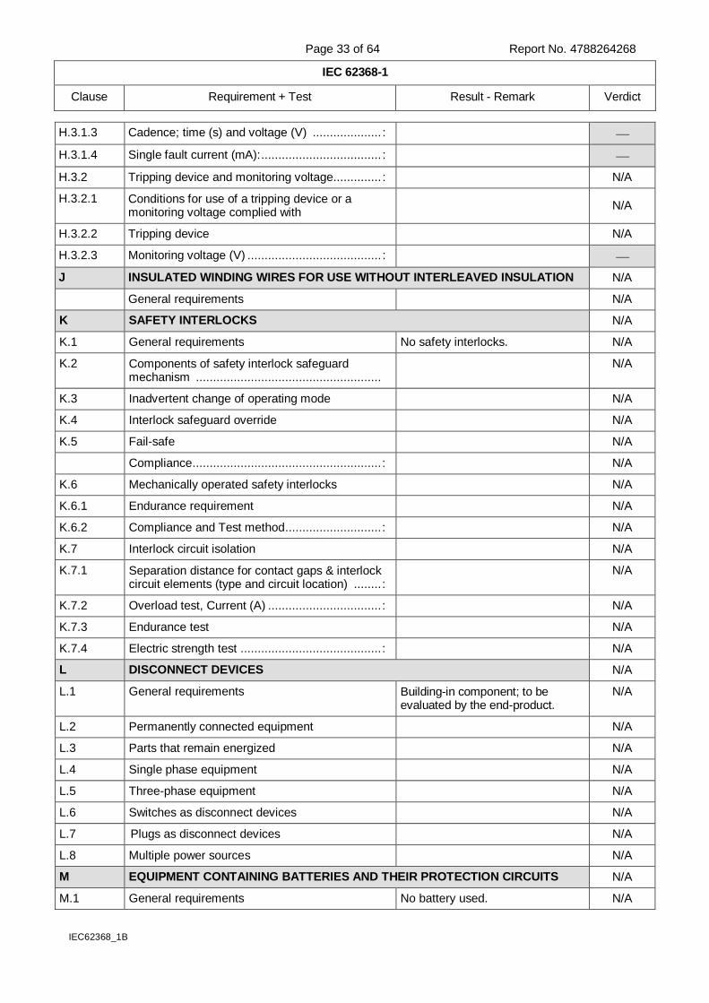
H.3.1.3 Cadence; time (s) and voltage (V) .................... :
H.3.1.4 Single fault current (mA): ................................... :
H.3.2 Tripping device and monitoring voltage.............. : N/A
H.3.2.1 Conditions for use of a tripping device or a monitoring voltage complied with
N/A
H.3.2.2 Tripping device N/A
H.3.2.3 Monitoring voltage (V) ....................................... :
J INSULATED WINDING WIRES FOR USE WITHOUT INTERLEAVED INSULATION N/A
General requirements N/A
K SAFETY INTERLOCKS N/A
K.1 General requirements No safety interlocks. N/A
K.2 Components of safety interlock safeguard mechanism ......................................................
N/A
K.3 Inadvertent change of operating mode N/A
K.4 Interlock safeguard override N/A
K.5 Fail-safe N/A
Compliance ....................................................... : N/A
K.6 Mechanically operated safety interlocks N/A
K.6.1 Endurance requirement N/A
K.6.2 Compliance and Test method ............................ : N/A
K.7 Interlock circuit isolation N/A
K.7.1 Separation distance for contact gaps & interlock circuit elements (type and circuit location) ........ :
N/A
K.7.2 Overload test, Current (A) ................................. : N/A
K.7.3 Endurance test N/A
K.7.4 Electric strength test ......................................... : N/A
L DISCONNECT DEVICES N/A
L.1 General requirements Building-in component; to be evaluated by the end-product.
N/A
L.2 Permanently connected equipment N/A
L.3 Parts that remain energized N/A
L.4 Single phase equipment N/A
L.5 Three-phase equipment N/A
L.6 Switches as disconnect devices N/A
L.7 Plugs as disconnect devices N/A
L.8 Multiple power sources N/A
M EQUIPMENT CONTAINING BATTERIES AND THEIR PROTECTION CIRCUITS N/A
M.1 General requirements No battery used. N/A
Page 34 of 64 Report No. 4788264268
IEC 62368-1
Clause Requirement + Test Result - Remark Verdict
IEC62368_1B
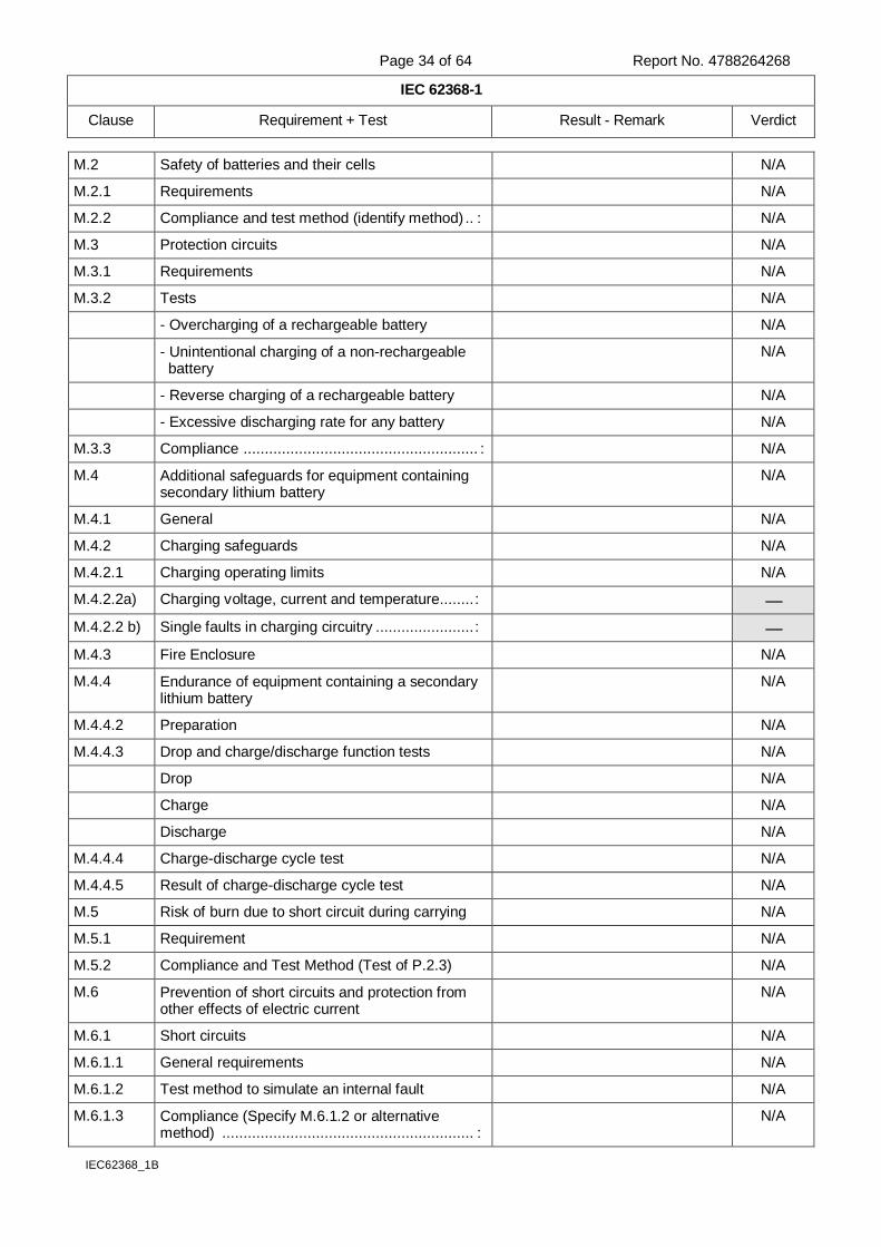
M.2 Safety of batteries and their cells N/A
M.2.1 Requirements N/A
M.2.2 Compliance and test method (identify method) .. : N/A
M.3 Protection circuits N/A
M.3.1 Requirements N/A
M.3.2 Tests N/A
- Overcharging of a rechargeable battery N/A
- Unintentional charging of a non-rechargeable battery
N/A
- Reverse charging of a rechargeable battery N/A
- Excessive discharging rate for any battery N/A
M.3.3 Compliance ....................................................... : N/A
M.4 Additional safeguards for equipment containing secondary lithium battery
N/A
M.4.1 General N/A
M.4.2 Charging safeguards N/A
M.4.2.1 Charging operating limits N/A
M.4.2.2a) Charging voltage, current and temperature ........ :
M.4.2.2 b) Single faults in charging circuitry ....................... :
M.4.3 Fire Enclosure N/A
M.4.4 Endurance of equipment containing a secondary lithium battery
N/A
M.4.4.2 Preparation N/A
M.4.4.3 Drop and charge/discharge function tests N/A
Drop N/A
Charge N/A
Discharge N/A
M.4.4.4 Charge-discharge cycle test N/A
M.4.4.5 Result of charge-discharge cycle test N/A
M.5 Risk of burn due to short circuit during carrying N/A
M.5.1 Requirement N/A
M.5.2 Compliance and Test Method (Test of P.2.3) N/A
M.6 Prevention of short circuits and protection from other effects of electric current
N/A
M.6.1 Short circuits N/A
M.6.1.1 General requirements N/A
M.6.1.2 Test method to simulate an internal fault N/A
M.6.1.3 Compliance (Specify M.6.1.2 or alternative method) ........................................................... :
N/A
Page 35 of 64 Report No. 4788264268
IEC 62368-1
Clause Requirement + Test Result - Remark Verdict
IEC62368_1B
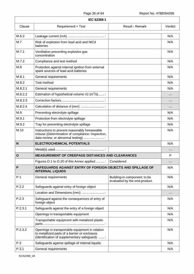
M.6.2 Leakage current (mA) ....................................... : N/A
M.7 Risk of explosion from lead acid and NiCd batteries
N/A
M.7.1 Ventilation preventing explosive gas concentration
N/A
M.7.2 Compliance and test method N/A
M.8 Protection against internal ignition from external spark sources of lead acid batteries
N/A
M.8.1 General requirements N/A
M.8.2 Test method N/A
M.8.2.1 General requirements N/A
M.8.2.2 Estimation of hypothetical volume Vz (m3/s) ...... :
M.8.2.3 Correction factors .............................................. :
M.8.2.4 Calculation of distance d (mm) ......................... :
M.9 Preventing electrolyte spillage N/A
M.9.1 Protection from electrolyte spillage N/A
M.9.2 Tray for preventing electrolyte spillage N/A
M.10 Instructions to prevent reasonably foreseeable misuse (Determination of compliance: inspection, data review; or abnormal testing) ...................... :
N/A
N ELECTROCHEMICAL POTENTIALS N/A
Metal(s) used .................................................... :
O MEASUREMENT OF CREEPAGE DISTANCES AND CLEARANCES P
Figures O.1 to O.20 of this Annex applied ......... : Considered.
P SAFEGUARDS AGAINST ENTRY OF FOREIGN OBJECTS AND SPILLAGE OF INTERNAL LIQUIDS
N/A
P.1 General requirements Building-in component; to be evaluated by the end-product.
N/A
P.2.2 Safeguards against entry of foreign object N/A
Location and Dimensions (mm) ........................ :
P.2.3 Safeguard against the consequences of entry of foreign object
N/A
P.2.3.1 Safeguards against the entry of a foreign object N/A
Openings in transportable equipment N/A
Transportable equipment with metalized plastic parts ................................................................. :
N/A
P.2.3.2 Openings in transportable equipment in relation to metallized parts of a barrier or enclosure (identification of supplementary safeguard) ...... :
N/A
P.3 Safeguards against spillage of internal liquids N/A
P.3.1 General requirements N/A
Page 36 of 64 Report No. 4788264268
IEC 62368-1
Clause Requirement + Test Result - Remark Verdict
IEC62368_1B
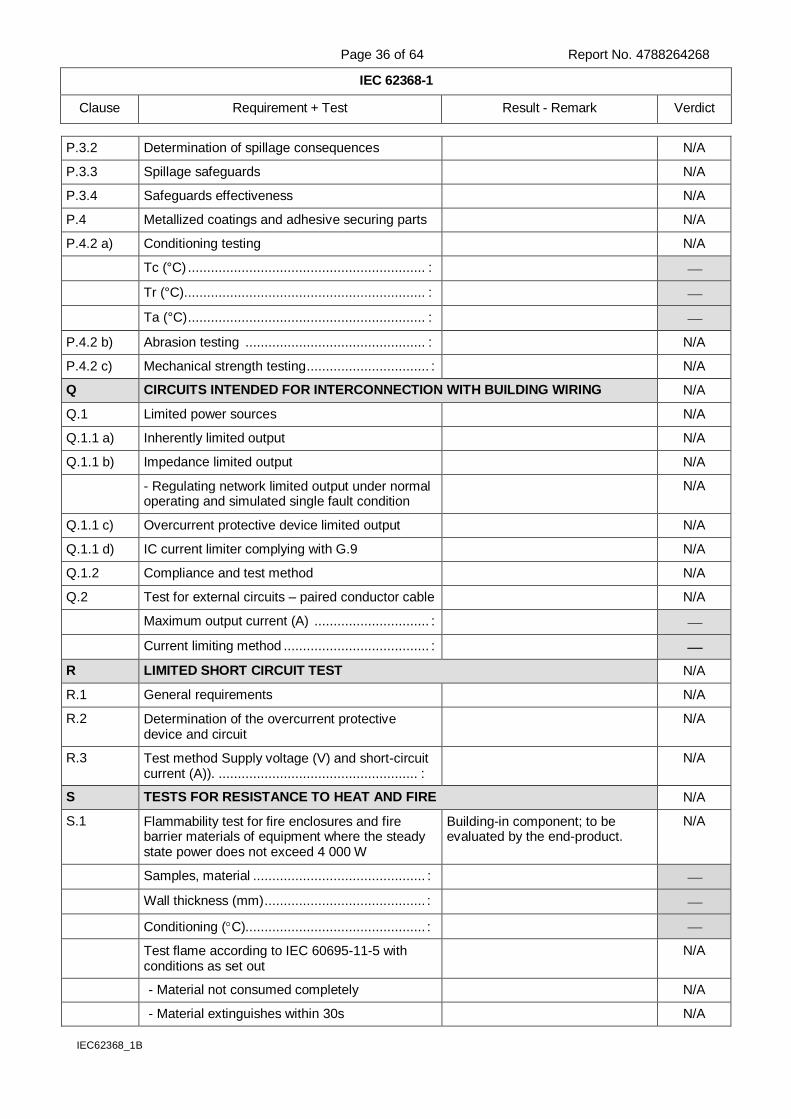
P.3.2 Determination of spillage consequences N/A
P.3.3 Spillage safeguards N/A
P.3.4 Safeguards effectiveness N/A
P.4 Metallized coatings and adhesive securing parts N/A
P.4.2 a) Conditioning testing N/A
Tc (°C) .............................................................. :
Tr (°C) ............................................................... :
Ta (°C) .............................................................. :
P.4.2 b) Abrasion testing ............................................... : N/A
P.4.2 c) Mechanical strength testing ................................ : N/A
Q CIRCUITS INTENDED FOR INTERCONNECTION WITH BUILDING WIRING N/A
Q.1 Limited power sources N/A
Q.1.1 a) Inherently limited output N/A
Q.1.1 b) Impedance limited output N/A
- Regulating network limited output under normal operating and simulated single fault condition
N/A
Q.1.1 c) Overcurrent protective device limited output N/A
Q.1.1 d) IC current limiter complying with G.9 N/A
Q.1.2 Compliance and test method N/A
Q.2 Test for external circuits – paired conductor cable N/A
Maximum output current (A) .............................. :
Current limiting method ...................................... :
R LIMITED SHORT CIRCUIT TEST N/A
R.1 General requirements N/A
R.2 Determination of the overcurrent protective device and circuit
N/A
R.3 Test method Supply voltage (V) and short-circuit current (A)). .................................................... :
N/A
S TESTS FOR RESISTANCE TO HEAT AND FIRE N/A
S.1 Flammability test for fire enclosures and fire barrier materials of equipment where the steady state power does not exceed 4 000 W
Building-in component; to be evaluated by the end-product.
N/A
Samples, material ............................................. :
Wall thickness (mm) .......................................... :
Conditioning (C)............................................... :
Test flame according to IEC 60695-11-5 with conditions as set out
N/A
- Material not consumed completely N/A
- Material extinguishes within 30s N/A
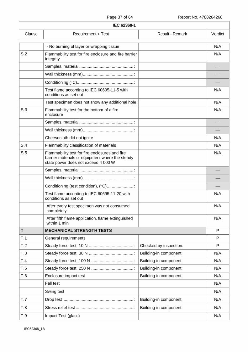
Page 37 of 64 Report No. 4788264268
IEC 62368-1
Clause Requirement + Test Result - Remark Verdict
IEC62368_1B
- No burning of layer or wrapping tissue N/A
S.2 Flammability test for fire enclosure and fire barrier integrity
N/A
Samples, material ............................................. :
Wall thickness (mm) .......................................... :
Conditioning (C)............................................... :
Test flame according to IEC 60695-11-5 with conditions as set out
N/A
Test specimen does not show any additional hole N/A
S.3 Flammability test for the bottom of a fire enclosure
N/A
Samples, material ............................................. :
Wall thickness (mm) .......................................... :
Cheesecloth did not ignite N/A
S.4 Flammability classification of materials N/A
S.5 Flammability test for fire enclosures and fire barrier materials of equipment where the steady state power does not exceed 4 000 W
N/A
Samples, material ............................................. :
Wall thickness (mm) .......................................... :
Conditioning (test condition), (C) ...................... :
Test flame according to IEC 60695-11-20 with conditions as set out
N/A
After every test specimen was not consumed completely
N/A
After fifth flame application, flame extinguished within 1 min
N/A
T MECHANICAL STRENGTH TESTS P
T.1 General requirements P
T.2 Steady force test, 10 N ..................................... : Checked by inspection. P
T.3 Steady force test, 30 N ..................................... : Building-in component. N/A
T.4 Steady force test, 100 N ................................... : Building-in component. N/A
T.5 Steady force test, 250 N ................................... : Building-in component. N/A
T.6 Enclosure impact test Building-in component. N/A
Fall test N/A
Swing test N/A
T.7 Drop test .......................................................... : Building-in component. N/A
T.8 Stress relief test ................................................ : Building-in component. N/A
T.9 Impact Test (glass) N/A
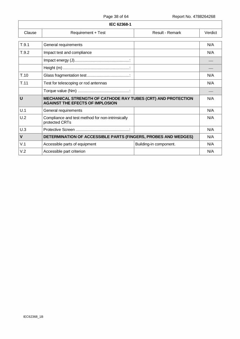
Page 38 of 64 Report No. 4788264268
IEC 62368-1
Clause Requirement + Test Result - Remark Verdict
IEC62368_1B
T.9.1 General requirements N/A
T.9.2 Impact test and compliance N/A
Impact energy (J) ............................................... :
Height (m) ......................................................... :
T.10 Glass fragmentation test .................................... : N/A
T.11 Test for telescoping or rod antennas N/A
Torque value (Nm) ............................................ :
U MECHANICAL STRENGTH OF CATHODE RAY TUBES (CRT) AND PROTECTION AGAINST THE EFECTS OF IMPLOSION
N/A
U.1 General requirements N/A
U.2 Compliance and test method for non-intrinsically protected CRTs
N/A
U.3 Protective Screen .............................................. : N/A
V DETERMINATION OF ACCESSIBLE PARTS (FINGERS, PROBES AND WEDGES) N/A
V.1 Accessible parts of equipment Building-in component. N/A
V.2 Accessible part criterion N/A
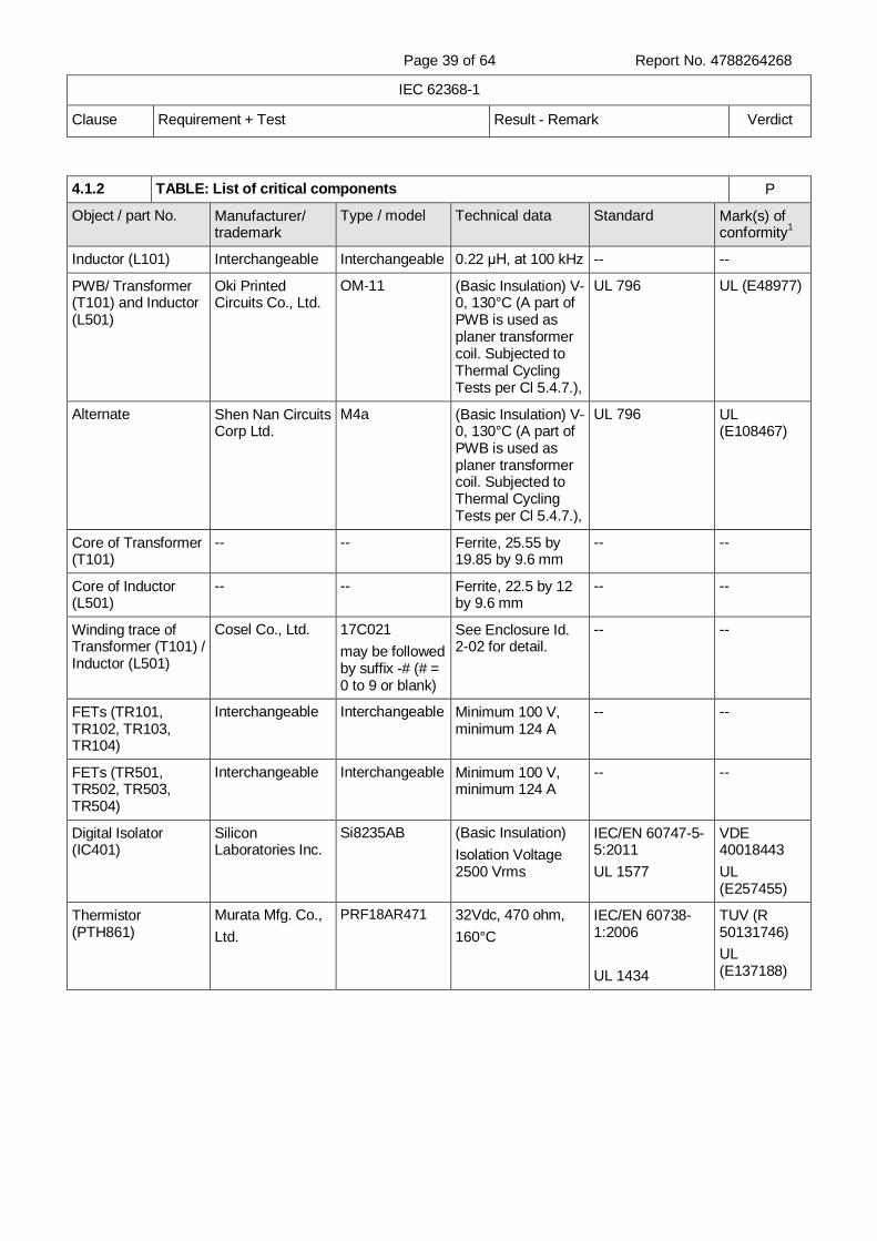
Page 39 of 64 Report No. 4788264268
IEC 62368-1
Clause Requirement + Test Result - Remark Verdict
4.1.2 TABLE: List of critical components P
Object / part No. Manufacturer/ trademark
Type / model Technical data Standard Mark(s) of conformity
1
Inductor (L101) Interchangeable Interchangeable 0.22 μH, at 100 kHz -- --
PWB/ Transformer (T101) and Inductor (L501)
Oki Printed Circuits Co., Ltd.
OM-11 (Basic Insulation) V-0, 130°C (A part of PWB is used as planer transformer coil. Subjected to Thermal Cycling Tests per Cl 5.4.7.),
UL 796 UL (E48977)
Alternate Shen Nan Circuits Corp Ltd.
M4a (Basic Insulation) V-0, 130°C (A part of PWB is used as planer transformer coil. Subjected to Thermal Cycling Tests per Cl 5.4.7.),
UL 796 UL (E108467)
Core of Transformer (T101)
-- -- Ferrite, 25.55 by 19.85 by 9.6 mm
-- --
Core of Inductor (L501)
-- -- Ferrite, 22.5 by 12 by 9.6 mm
-- --
Winding trace of Transformer (T101) / Inductor (L501)
Cosel Co., Ltd. 17C021
may be followed by suffix -# (# = 0 to 9 or blank)
See Enclosure Id. 2-02 for detail.
-- --
FETs (TR101, TR102, TR103, TR104)
Interchangeable Interchangeable Minimum 100 V, minimum 124 A
-- --
FETs (TR501, TR502, TR503, TR504)
Interchangeable Interchangeable Minimum 100 V, minimum 124 A
-- --
Digital Isolator (IC401)
Silicon Laboratories Inc.
Si8235AB (Basic Insulation)
Isolation Voltage 2500 Vrms
IEC/EN 60747-5-5:2011
UL 1577
VDE 40018443
UL (E257455)
Thermistor (PTH861)
Murata Mfg. Co.,
Ltd.
PRF18AR471 32Vdc, 470 ohm,
160°C
IEC/EN 60738-1:2006
UL 1434
TUV (R 50131746)
UL (E137188)
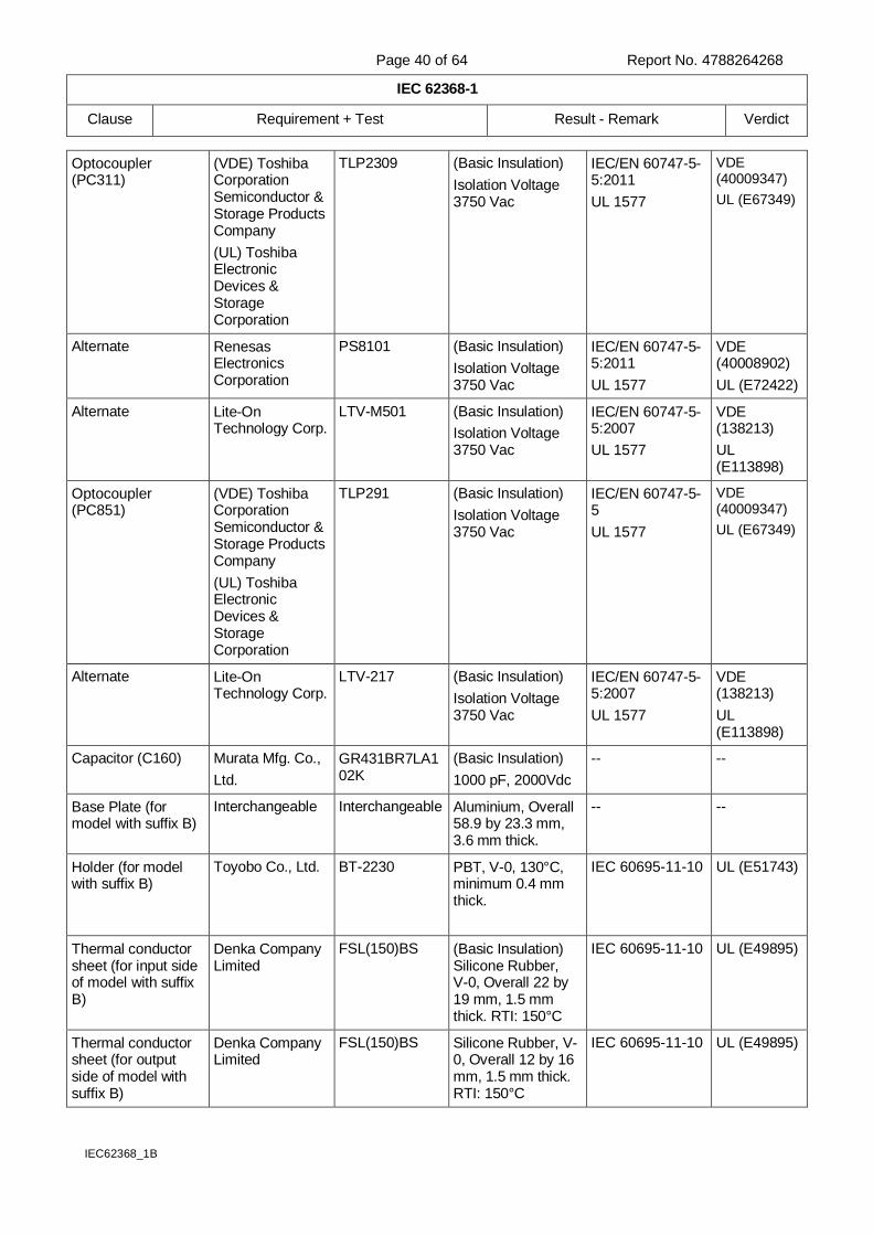
Page 40 of 64 Report No. 4788264268
IEC 62368-1
Clause Requirement + Test Result - Remark Verdict
IEC62368_1B
Optocoupler (PC311)
(VDE) Toshiba Corporation Semiconductor & Storage Products Company
(UL) Toshiba Electronic Devices & Storage Corporation
TLP2309 (Basic Insulation)
Isolation Voltage 3750 Vac
IEC/EN 60747-5-5:2011
UL 1577
VDE (40009347)
UL (E67349)
Alternate Renesas Electronics Corporation
PS8101 (Basic Insulation)
Isolation Voltage 3750 Vac
IEC/EN 60747-5-5:2011
UL 1577
VDE (40008902)
UL (E72422)
Alternate Lite-On Technology Corp.
LTV-M501 (Basic Insulation)
Isolation Voltage 3750 Vac
IEC/EN 60747-5-5:2007
UL 1577
VDE (138213)
UL (E113898)
Optocoupler (PC851)
(VDE) Toshiba Corporation Semiconductor & Storage Products Company
(UL) Toshiba Electronic Devices & Storage Corporation
TLP291 (Basic Insulation)
Isolation Voltage 3750 Vac
IEC/EN 60747-5-5
UL 1577
VDE (40009347)
UL (E67349)
Alternate Lite-On Technology Corp.
LTV-217 (Basic Insulation)
Isolation Voltage 3750 Vac
IEC/EN 60747-5-5:2007
UL 1577
VDE (138213)
UL (E113898)
Capacitor (C160) Murata Mfg. Co.,
Ltd.
GR431BR7LA102K
(Basic Insulation)
1000 pF, 2000Vdc
-- --
Base Plate (for model with suffix B)
Interchangeable Interchangeable Aluminium, Overall 58.9 by 23.3 mm, 3.6 mm thick.
-- --
Holder (for model with suffix B)
Toyobo Co., Ltd. BT-2230 PBT, V-0, 130°C, minimum 0.4 mm thick.
IEC 60695-11-10 UL (E51743)
Thermal conductor sheet (for input side of model with suffix B)
Denka Company Limited
FSL(150)BS (Basic Insulation) Silicone Rubber, V-0, Overall 22 by 19 mm, 1.5 mm thick. RTI: 150°C
IEC 60695-11-10 UL (E49895)
Thermal conductor sheet (for output side of model with suffix B)
Denka Company Limited
FSL(150)BS Silicone Rubber, V-0, Overall 12 by 16 mm, 1.5 mm thick. RTI: 150°C
IEC 60695-11-10 UL (E49895)
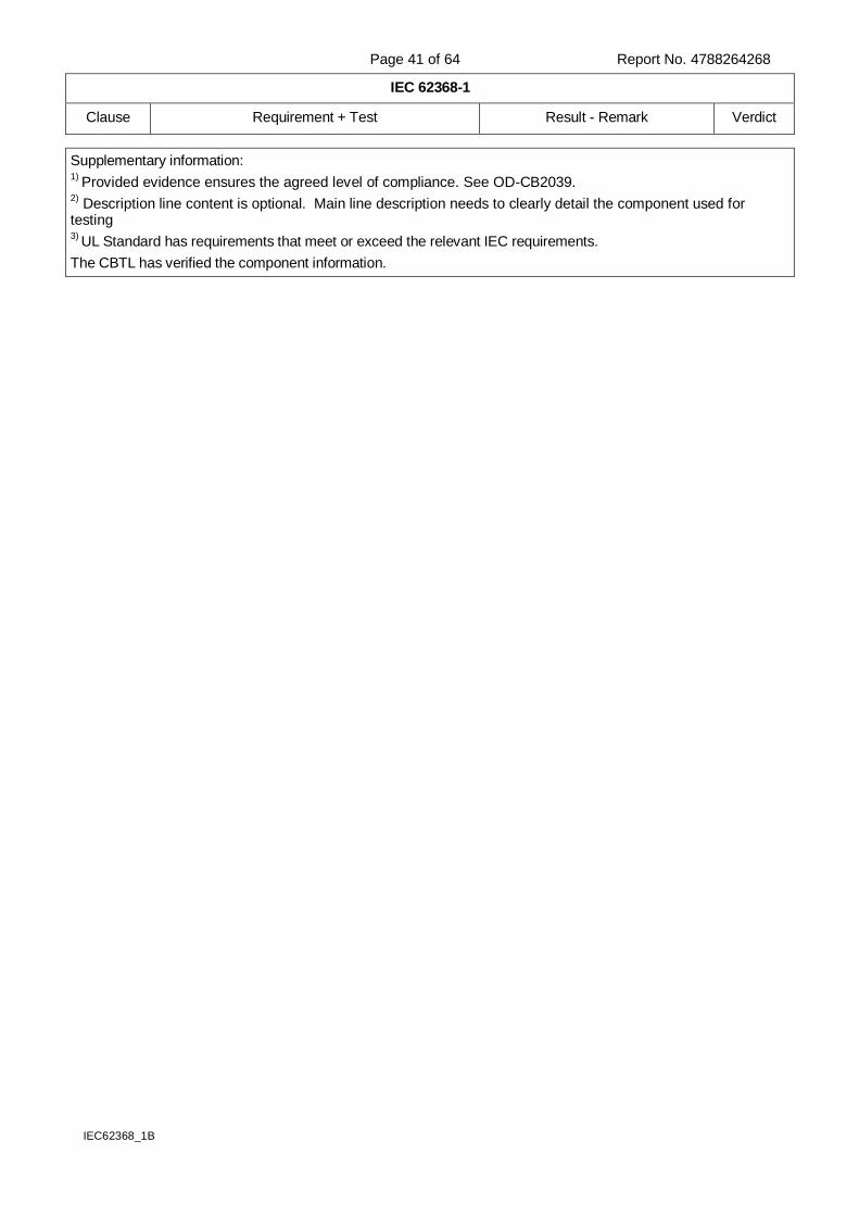
Page 41 of 64 Report No. 4788264268
IEC 62368-1
Clause Requirement + Test Result - Remark Verdict
IEC62368_1B
Supplementary information: 1)
Provided evidence ensures the agreed level of compliance. See OD-CB2039. 2)
Description line content is optional. Main line description needs to clearly detail the component used for testing 3)
UL Standard has requirements that meet or exceed the relevant IEC requirements.
The CBTL has verified the component information.
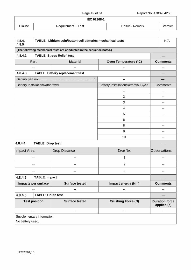
Page 42 of 64 Report No. 4788264268
IEC 62368-1
Clause Requirement + Test Result - Remark Verdict
IEC62368_1B
4.8.4, 4.8.5
TABLE: Lithium coin/button cell batteries mechanical tests N/A
(The following mechanical tests are conducted in the sequence noted.)
4.8.4.2 TABLE: Stress Relief test
Part Material Oven Temperature (°C) Comments
-- -- -- --
4.8.4.3 TABLE: Battery replacement test
Battery part no. ........................................................... : -- —
Battery Installation/withdrawal Battery Installation/Removal Cycle Comments
1 --
2 --
3 --
4 --
5 --
6 --
8 --
9 --
10 --
4.8.4.4 TABLE: Drop test
Impact Area Drop Distance Drop No. Observations
-- -- 1 --
-- -- 2 --
-- -- 3 --
4.8.4.5 TABLE: Impact
Impacts per surface Surface tested Impact energy (Nm) Comments
-- -- -- --
4.8.4.6 TABLE: Crush test
Test position Surface tested Crushing Force (N) Duration force applied (s)
-- -- -- --
Supplementary information:
No battery used.
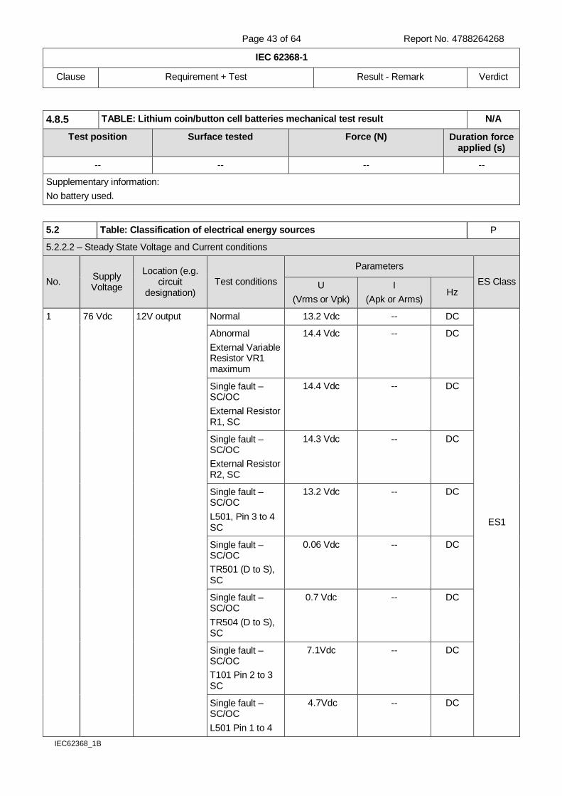
Page 43 of 64 Report No. 4788264268
IEC 62368-1
Clause Requirement + Test Result - Remark Verdict
IEC62368_1B
4.8.5 TABLE: Lithium coin/button cell batteries mechanical test result N/A
Test position Surface tested Force (N) Duration force applied (s)
-- -- -- --
Supplementary information:
No battery used.
5.2 Table: Classification of electrical energy sources P
5.2.2.2 – Steady State Voltage and Current conditions
No. Supply Voltage
Location (e.g. circuit
designation) Test conditions
Parameters
ES Class U
(Vrms or Vpk)
I
(Apk or Arms) Hz
1 76 Vdc 12V output Normal 13.2 Vdc -- DC
ES1
Abnormal
External Variable Resistor VR1 maximum
14.4 Vdc -- DC
Single fault –SC/OC
External Resistor R1, SC
14.4 Vdc -- DC
Single fault –SC/OC
External Resistor R2, SC
14.3 Vdc -- DC
Single fault –SC/OC
L501, Pin 3 to 4 SC
13.2 Vdc -- DC
Single fault – SC/OC
TR501 (D to S), SC
0.06 Vdc -- DC
Single fault – SC/OC
TR504 (D to S), SC
0.7 Vdc -- DC
Single fault – SC/OC
T101 Pin 2 to 3 SC
7.1Vdc -- DC
Single fault – SC/OC
L501 Pin 1 to 4
4.7Vdc -- DC
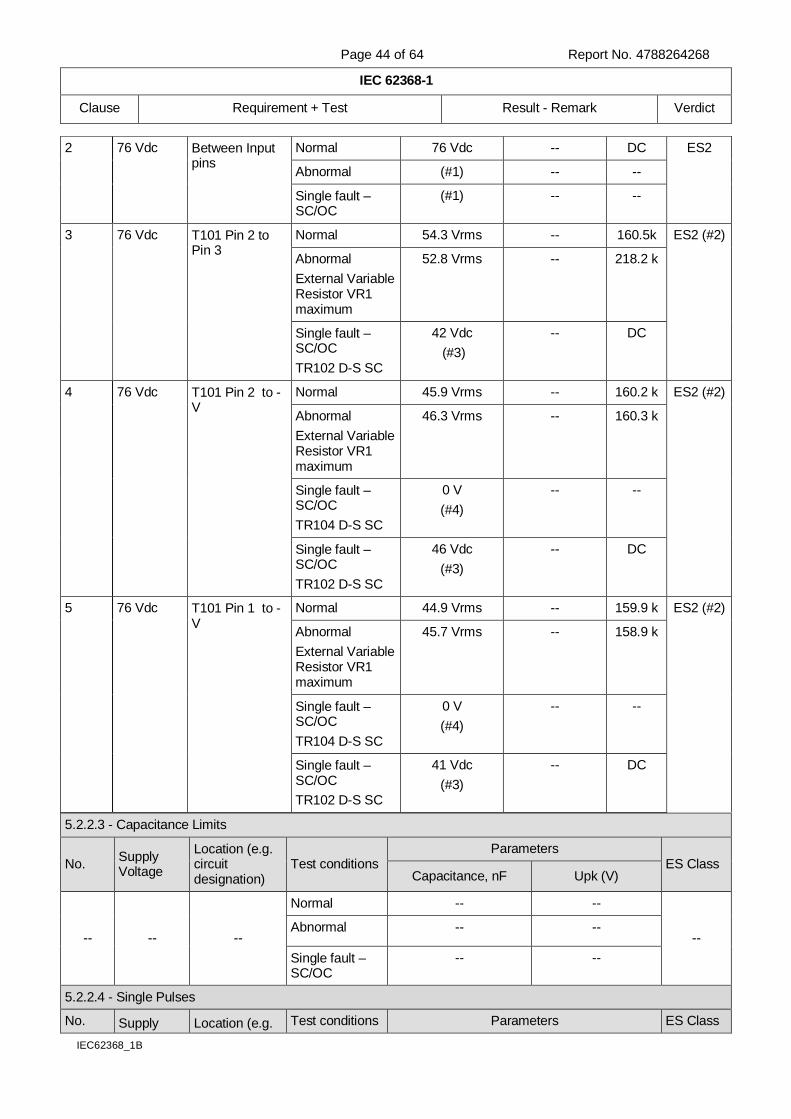
Page 44 of 64 Report No. 4788264268
IEC 62368-1
Clause Requirement + Test Result - Remark Verdict
IEC62368_1B
5.2.2.3 - Capacitance Limits
No. Supply Voltage
Location (e.g. circuit designation)
Test conditions Parameters
ES Class Capacitance, nF Upk (V)
-- -- --
Normal -- --
-- Abnormal -- --
Single fault – SC/OC
-- --
5.2.2.4 - Single Pulses
No. Supply Location (e.g. Test conditions Parameters ES Class
2 76 Vdc Between Input pins
Normal 76 Vdc -- DC ES2
Abnormal (#1) -- --
Single fault – SC/OC
(#1) -- --
3 76 Vdc T101 Pin 2 to Pin 3
Normal 54.3 Vrms -- 160.5k ES2 (#2)
Abnormal
External Variable Resistor VR1 maximum
52.8 Vrms -- 218.2 k
Single fault – SC/OC
TR102 D-S SC
42 Vdc
(#3)
-- DC
4 76 Vdc T101 Pin 2 to -V
Normal 45.9 Vrms -- 160.2 k ES2 (#2)
Abnormal
External Variable Resistor VR1 maximum
46.3 Vrms -- 160.3 k
Single fault – SC/OC
TR104 D-S SC
0 V
(#4)
-- --
Single fault – SC/OC
TR102 D-S SC
46 Vdc
(#3)
-- DC
5 76 Vdc T101 Pin 1 to -V
Normal 44.9 Vrms -- 159.9 k ES2 (#2)
Abnormal
External Variable Resistor VR1 maximum
45.7 Vrms -- 158.9 k
Single fault – SC/OC
TR104 D-S SC
0 V
(#4)
-- --
Single fault – SC/OC
TR102 D-S SC
41 Vdc
(#3)
-- DC

Page 45 of 64 Report No. 4788264268
IEC 62368-1
Clause Requirement + Test Result - Remark Verdict
IEC62368_1B
Voltage circuit designation) Duration (ms) Upk (V) Ipk (mA)
-- -- --
Normal -- -- --
-- Abnormal -- -- --
Single fault – SC/OC
-- -- --
5.2.2.5 - Repetitive Pulses
No. Supply Voltage
Location (e.g. circuit designation)
Test conditions Parameters
ES Class Off time (ms) Upk (V) Ipk (mA)
-- -- --
Normal -- -- --
-- Abnormal -- -- --
Single fault – SC/OC
-- -- --
Test Conditions:
Normal – Maximum voltage within output voltage range.
Abnormal - External Variable Resistor VR1 maximum
Single fault - External Resistor R1, SC / External Resistor R2, SC / L501, SC / TR501 (D to S), SC / TR504 (D to S), SC / TR102 (D to S), SC / TR104 (D to S), CS
Supplementary information: SC=Short Circuit, OC=Short Circuit
(#1): Power source from ES2 external power supply, abnormal condition and Single fault condition are unnecessary.
(#2): Although the input side circuit boosts the voltage by the switching circuit, it was confirmed that it does not exceed ES 2 limit by circuit analysis and test.
(#3): Unit shutdown immediately, the voltage remained and gradually reduced.
(#4): Unit shut down immediately.
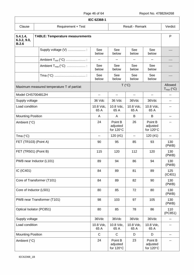
Page 46 of 64 Report No. 4788264268
IEC 62368-1
Clause Requirement + Test Result - Remark Verdict
IEC62368_1B
5.4.1.4, 6.3.2, 9.0, B.2.6
TABLE: Temperature measurements P
Supply voltage (V) ................... : See below
See below
See below
See below
Ambient Tmin (C) ..................... : -- -- -- --
Ambient Tmax (C) .................... : See below
See below
See below
See below
Tma (C) ................................. : See below
See below
See below
See below
Maximum measured temperature T of part/at: T (C) Allowed
Tmax (C)
Model CHS7004812H -- -- -- -- --
Supply voltage 36 Vdc 36 Vdc 36Vdc 36Vdc --
Load condition 10.8 Vdc, 65 A
10.8 Vdc, 65 A
10.8 Vdc, 65 A
10.8 Vdc, 65 A
--
Mounting Position A A B B --
Ambient (C) 24 Point B adjusted
for 120C
26 Point B adjusted
for 120C
--
Tma (C) -- 120 (#1) -- 120 (#1) --
FET (TR103) (Point A) 90 95 85 93 130 (PWB)
FET (TR501) (Point B) 115 120 112 120 130 (PWB)
PWB near Inductor (L101) 89 94 86 94 130 (PWB)
IC (IC401) 84 89 81 89 125 (IC401)
Core of Transformer (T101) 84 89 82 90 130 (PWB)
Core of Inductor (L501) 80 85 72 80 130 (PWB)
PWB near Transformer (T101) 98 103 97 105 130 (PWB)
Optical Isolator (PC851) 80 85 78 86 110 (PC851)
Supply voltage 36Vdc 36Vdc 36Vdc 36Vdc --
Load condition 10.8 Vdc, 65 A
10.8 Vdc, 65 A
10.8 Vdc, 65 A
10.8 Vdc, 65 A
--
Mounting Position C C D D --
Ambient (C) 24 Point B adjusted
for 120C
23 Point B adjusted
for 120C
--

Page 47 of 64 Report No. 4788264268
IEC 62368-1
Clause Requirement + Test Result - Remark Verdict
IEC62368_1B
Tma (C) -- 120 (#1) -- 120 (#1) --
FET (TR103) (Point A) 89 93 74 80 130 (PWB)
FET (TR501) (Point B) 116 120 114 120 130 (PWB)
PWB near Inductor (L101) 91 95 87 93 130 (PWB)
IC (IC401) 81 85 81 87 125 (IC401)
Core of Transformer (T101) 87 91 82 88 130 (PWB)
Core of Inductor (L501) 79 83 73 79 130 (PWB)
PWB near Transformer (T101) 99 103 96 102 130 (PWB)
Optical Isolator (PC851) 80 84 79 85 110 (PC851)
Supply voltage 36Vdc 36Vdc 36Vdc 36Vdc --
Load condition 10.8 Vdc, 65 A
10.8 Vdc, 65 A
10.8 Vdc, 65 A
10.8 Vdc, 65 A
--
Mounting Position E E F F --
Ambient (C) 24 Point B adjusted
for 120C
24 Point B adjusted
for 120C
--
Tma (C) -- 120 (#1) -- 120 (#1) --
FET (TR103) (Point A) 74 80 68 77 130 (PWB)
FET (TR501) (Point B) 114 120 111 120 130 (PWB)
PWB near Inductor (L101) 88 94 85 94 130 (PWB)
IC (IC401) 82 88 80 89 125 (IC401)
Core of Transformer (T101) 83 89 80 89 130 (PWB)
Core of Inductor (L501) 73 79 72 81 130 (PWB)
PWB near Transformer (T101) 96 102 94 103 130 (PWB)
Optical Isolator (PC851) 79 85 77 86 110 (PC851)
Supply voltage 76 Vdc 76Vdc 76Vdc 76Vdc --
Load condition 12 Vdc, 58.5 A
12 Vdc, 58.5 A
12 Vdc, 58.5 A
12 Vdc, 58.5 A
--
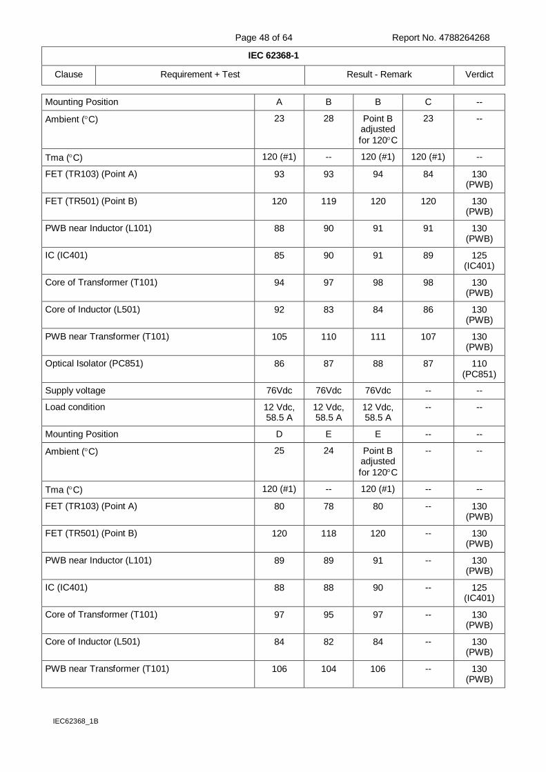
Page 48 of 64 Report No. 4788264268
IEC 62368-1
Clause Requirement + Test Result - Remark Verdict
IEC62368_1B
Mounting Position A B B C --
Ambient (C) 23 28 Point B adjusted
for 120C
23 --
Tma (C) 120 (#1) -- 120 (#1) 120 (#1) --
FET (TR103) (Point A) 93 93 94 84 130 (PWB)
FET (TR501) (Point B) 120 119 120 120 130 (PWB)
PWB near Inductor (L101) 88 90 91 91 130 (PWB)
IC (IC401) 85 90 91 89 125 (IC401)
Core of Transformer (T101) 94 97 98 98 130 (PWB)
Core of Inductor (L501) 92 83 84 86 130 (PWB)
PWB near Transformer (T101) 105 110 111 107 130 (PWB)
Optical Isolator (PC851) 86 87 88 87 110 (PC851)
Supply voltage 76Vdc 76Vdc 76Vdc -- --
Load condition 12 Vdc, 58.5 A
12 Vdc, 58.5 A
12 Vdc, 58.5 A
-- --
Mounting Position D E E -- --
Ambient (C) 25 24 Point B adjusted
for 120C
-- --
Tma (C) 120 (#1) -- 120 (#1) -- --
FET (TR103) (Point A) 80 78 80 -- 130 (PWB)
FET (TR501) (Point B) 120 118 120 -- 130 (PWB)
PWB near Inductor (L101) 89 89 91 -- 130 (PWB)
IC (IC401) 88 88 90 -- 125 (IC401)
Core of Transformer (T101) 97 95 97 -- 130 (PWB)
Core of Inductor (L501) 84 82 84 -- 130 (PWB)
PWB near Transformer (T101) 106 104 106 -- 130 (PWB)
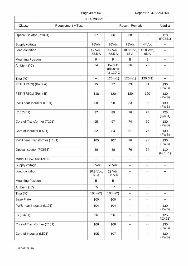
Page 49 of 64 Report No. 4788264268
IEC 62368-1
Clause Requirement + Test Result - Remark Verdict
IEC62368_1B
Optical Isolator (PC851) 87 86 88 -- 110 (PC851)
Supply voltage 76Vdc 76Vdc 76Vdc 44Vdc --
Load condition 12 Vdc, 58.5 A
12 Vdc, 58.5 A
10.8 Vdc, 65 A
10.8 Vdc, 65 A
--
Mounting Position F F B B --
Ambient (C) 24 Point B adjusted
for 120C
26 26 --
Tma (C) -- 120 (#1) 120 (#1) 120 (#1) --
FET (TR103) (Point A) 75 77 83 81 130 (PWB)
FET (TR501) (Point B) 118 120 120 120 130 (PWB)
PWB near Inductor (L101) 88 90 83 85 130 (PWB)
IC (IC401) 87 89 76 73 125 (IC401)
Core of Transformer (T101) 95 97 74 70 130 (PWB)
Core of Inductor (L501) 82 84 81 76 130 (PWB)
PWB near Transformer (T101) 105 107 96 93 130 (PWB)
Optical Isolator (PC851) 86 88 76 74 110 (PC851)
Model CHS7004812H-B -- -- -- -- --
Supply voltage 36Vdc 76Vdc -- -- --
Load condition 10.8 Vdc, 65 A
12 Vdc, 58.5 A
-- -- --
Mounting Position B B -- -- --
Ambient (C) 25 27 -- -- --
Tma (C) 100 (#2) 100 (#2) -- -- --
Base Plate 100 100 -- -- --
PWB near Inductor (L101) 104 104 -- -- 130 (PWB)
IC (IC401) 96 96 -- -- 125 (IC401)
Core of Transformer (T101) 106 108 -- -- 130 (PWB)
Core of Inductor (L501) 105 107 -- -- 130 (PWB)
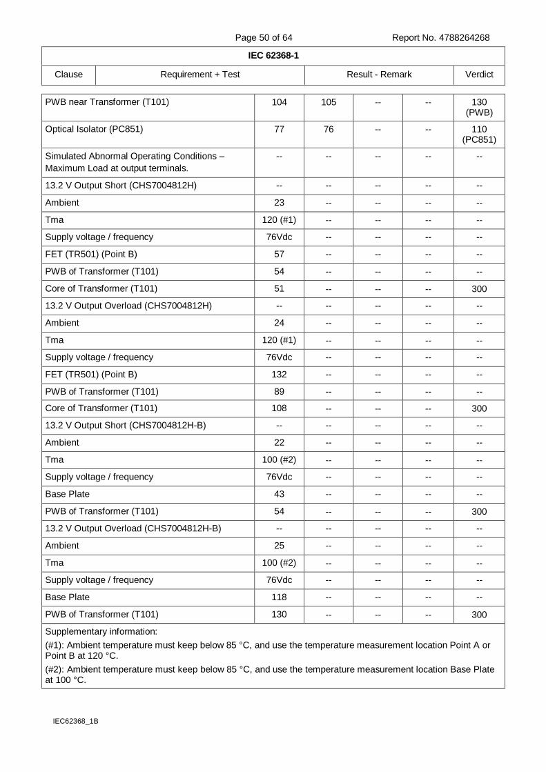
Page 50 of 64 Report No. 4788264268
IEC 62368-1
Clause Requirement + Test Result - Remark Verdict
IEC62368_1B
PWB near Transformer (T101) 104 105 -- -- 130 (PWB)
Optical Isolator (PC851) 77 76 -- -- 110 (PC851)
Simulated Abnormal Operating Conditions –
Maximum Load at output terminals.
-- -- -- -- --
13.2 V Output Short (CHS7004812H) -- -- -- -- --
Ambient 23 -- -- -- --
Tma 120 (#1) -- -- -- --
Supply voltage / frequency 76Vdc -- -- -- --
FET (TR501) (Point B) 57 -- -- -- --
PWB of Transformer (T101) 54 -- -- -- --
Core of Transformer (T101) 51 -- -- -- 300
13.2 V Output Overload (CHS7004812H) -- -- -- -- --
Ambient 24 -- -- -- --
Tma 120 (#1) -- -- -- --
Supply voltage / frequency 76Vdc -- -- -- --
FET (TR501) (Point B) 132 -- -- -- --
PWB of Transformer (T101) 89 -- -- -- --
Core of Transformer (T101) 108 -- -- -- 300
13.2 V Output Short (CHS7004812H-B) -- -- -- -- --
Ambient 22 -- -- -- --
Tma 100 (#2) -- -- -- --
Supply voltage / frequency 76Vdc -- -- -- --
Base Plate 43 -- -- -- --
PWB of Transformer (T101) 54 -- -- -- 300
13.2 V Output Overload (CHS7004812H-B) -- -- -- -- --
Ambient 25 -- -- -- --
Tma 100 (#2) -- -- -- --
Supply voltage / frequency 76Vdc -- -- -- --
Base Plate 118 -- -- -- --
PWB of Transformer (T101) 130 -- -- -- 300
Supplementary information:
(#1): Ambient temperature must keep below 85 °C, and use the temperature measurement location Point A or Point B at 120 °C.
(#2): Ambient temperature must keep below 85 °C, and use the temperature measurement location Base Plate at 100 °C.
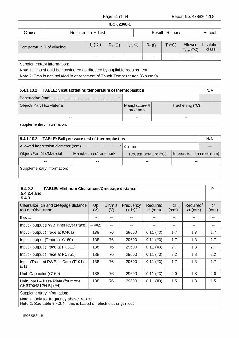
Page 51 of 64 Report No. 4788264268
IEC 62368-1
Clause Requirement + Test Result - Remark Verdict
IEC62368_1B
Temperature T of winding: t1 (°C) R1 () t2 (°C) R2 () T (C) Allowed
Tmax (C)
Insulation class
-- -- -- -- -- -- -- --
Supplementary information:
Note 1: Tma should be considered as directed by appliable requirement
Note 2: Tma is not included in assessment of Touch Temperatures (Clause 9)
5.4.1.10.2 TABLE: Vicat softening temperature of thermoplastics N/A
Penetration (mm) ..................................................... :
Object/ Part No./Material Manufacturer/trademark
T softening (°C)
-- -- --
supplementary information:
5.4.1.10.3 TABLE: Ball pressure test of thermoplastics N/A
Allowed impression diameter (mm) ................................ : 2 mm
Object/Part No./Material Manufacturer/trademark Test temperature (C) Impression diameter (mm)
-- -- -- --
Supplementary information:
5.4.2.2, 5.4.2.4 and 5.4.3
TABLE: Minimum Clearances/Creepage distance P
Clearance (cl) and creepage distance (cr) at/of/between:
Up (V)
U r.m.s. (V)
Frequency (kHz)
1
Required cl (mm)
cl (mm)
2
Required3
cr (mm) cr
(mm)
Basic: -- -- -- -- -- -- --
Input - output (PWB inner layer trace) -- (#2) -- -- -- -- -- --
Input - output (Trace at IC401) 138 76 29600 0.11 (#3) 1.7 1.3 1.7
Input - output (Trace at C160) 138 76 29600 0.11 (#3) 1.7 1.3 1.7
Input - output (Trace at PC311) 138 76 29600 0.11 (#3) 2.7 1.3 2.7
Input - output (Trace at PC851) 138 76 29600 0.11 (#3) 2.2 1.3 2.2
Input (Trace at PWB) – Core (T101) (#1)
138 76 29600 0.11 (#3) 1.7 1.3 1.7
Unit: Capacitor (C160) 138 76 29600 0.11 (#3) 2.0 1.3 2.0
Unit: Input – Base Plate (for model CHS7004812H-B) (#4)
138 76 29600 0.11 (#3) 1.5 1.3 1.5
Supplementary information:
Note 1: Only for frequency above 30 kHz Note 2: See table 5.4.2.4 if this is based on electric strength test
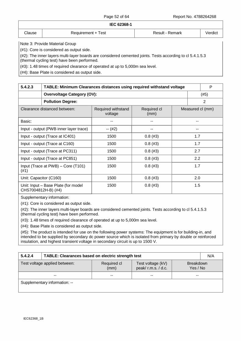
Page 52 of 64 Report No. 4788264268
IEC 62368-1
Clause Requirement + Test Result - Remark Verdict
IEC62368_1B
Note 3: Provide Material Group
(#1): Core is considered as output side.
(#2): The inner layers multi-layer boards are considered cemented joints. Tests according to cl 5.4.1.5.3 (thermal cycling test) have been performed.
(#3): 1.48 times of required clearance of operated at up to 5,000m sea level.
(#4): Base Plate is considered as output side.
5.4.2.3 TABLE: Minimum Clearances distances using required withstand voltage P
Overvoltage Category (OV): (#5)
Pollution Degree: 2
Clearance distanced between: Required withstand voltage
Required cl (mm)
Measured cl (mm)
Basic: -- -- --
Input - output (PWB inner layer trace) -- (#2) -- --
Input - output (Trace at IC401) 1500 0.8 (#3) 1.7
Input - output (Trace at C160) 1500 0.8 (#3) 1.7
Input - output (Trace at PC311) 1500 0.8 (#3) 2.7
Input - output (Trace at PC851) 1500 0.8 (#3) 2.2
Input (Trace at PWB) – Core (T101) (#1)
1500 0.8 (#3) 1.7
Unit: Capacitor (C160) 1500 0.8 (#3) 2.0
Unit: Input – Base Plate (for model CHS7004812H-B) (#4)
1500 0.8 (#3) 1.5
Supplementary information:
(#1): Core is considered as output side.
(#2): The inner layers multi-layer boards are considered cemented joints. Tests according to cl 5.4.1.5.3 (thermal cycling test) have been performed.
(#3): 1.48 times of required clearance of operated at up to 5,000m sea level.
(#4): Base Plate is considered as output side.
(#5): The product is intended for use on the following power systems: The equipment is for building-in, and intended to be supplied by secondary dc power source which is isolated from primary by double or reinforced insulation, and highest transient voltage in secondary circuit is up to 1500 V.
5.4.2.4 TABLE: Clearances based on electric strength test N/A
Test voltage applied between: Required cl (mm)
Test voltage (kV) peak/ r.m.s. / d.c.
Breakdown Yes / No
-- -- -- --
Supplementary information: --
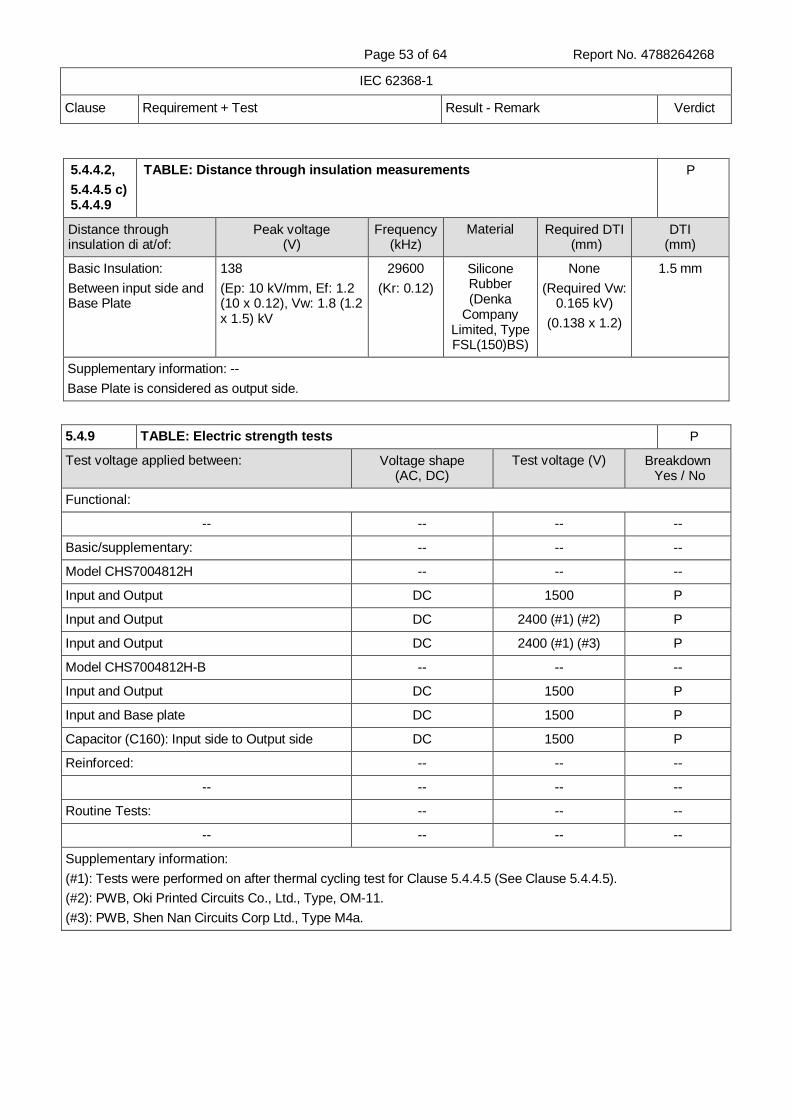
Page 53 of 64 Report No. 4788264268
IEC 62368-1
Clause Requirement + Test Result - Remark Verdict
5.4.4.2,
5.4.4.5 c) 5.4.4.9
TABLE: Distance through insulation measurements P
Distance through insulation di at/of:
Peak voltage (V)
Frequency (kHz)
Material Required DTI (mm)
DTI (mm)
Basic Insulation:
Between input side and Base Plate
138
(Ep: 10 kV/mm, Ef: 1.2 (10 x 0.12), Vw: 1.8 (1.2 x 1.5) kV
29600
(Kr: 0.12)
Silicone Rubber (Denka
Company Limited, Type FSL(150)BS)
None
(Required Vw: 0.165 kV)
(0.138 x 1.2)
1.5 mm
Supplementary information: --
Base Plate is considered as output side.
5.4.9 TABLE: Electric strength tests P
Test voltage applied between: Voltage shape (AC, DC)
Test voltage (V) Breakdown Yes / No
Functional:
-- -- -- --
Basic/supplementary: -- -- --
Model CHS7004812H -- -- --
Input and Output DC 1500 P
Input and Output DC 2400 (#1) (#2) P
Input and Output DC 2400 (#1) (#3) P
Model CHS7004812H-B -- -- --
Input and Output DC 1500 P
Input and Base plate DC 1500 P
Capacitor (C160): Input side to Output side DC 1500 P
Reinforced: -- -- --
-- -- -- --
Routine Tests: -- -- --
-- -- -- --
Supplementary information:
(#1): Tests were performed on after thermal cycling test for Clause 5.4.4.5 (See Clause 5.4.4.5).
(#2): PWB, Oki Printed Circuits Co., Ltd., Type, OM-11.
(#3): PWB, Shen Nan Circuits Corp Ltd., Type M4a.
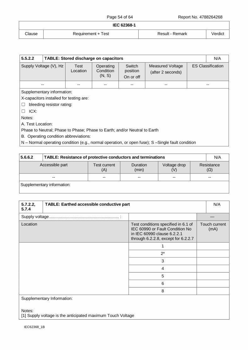
Page 54 of 64 Report No. 4788264268
IEC 62368-1
Clause Requirement + Test Result - Remark Verdict
IEC62368_1B
5.5.2.2 TABLE: Stored discharge on capacitors N/A
Supply Voltage (V), Hz Test Location
Operating Condition
(N, S)
Switch position
On or off
Measured Voltage
(after 2 seconds)
ES Classification
-- -- -- -- -- --
Supplementary information:
X-capacitors installed for testing are:
bleeding resistor rating:
ICX:
Notes:
A. Test Location:
Phase to Neutral; Phase to Phase; Phase to Earth; and/or Neutral to Earth
B. Operating condition abbreviations:
N – Normal operating condition (e.g., normal operation, or open fuse); S –Single fault condition
5.6.6.2 TABLE: Resistance of protective conductors and terminations N/A
Accessible part Test current (A)
Duration (min)
Voltage drop (V)
Resistance (Ω)
-- -- -- -- --
Supplementary information:
5.7.2.2, 5.7.4
TABLE: Earthed accessible conductive part N/A
Supply voltage .......................................................... : —
Location Test conditions specified in 6.1 of IEC 60990 or Fault Condition No in IEC 60990 clause 6.2.2.1 through 6.2.2.8, except for 6.2.2.7
Touch current (mA)
1
2*
3
4
5
6
8
Supplementary Information:
Notes: [1] Supply voltage is the anticipated maximum Touch Voltage
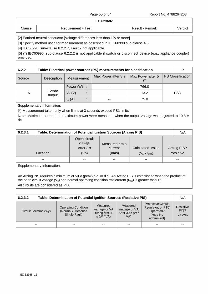
Page 55 of 64 Report No. 4788264268
IEC 62368-1
Clause Requirement + Test Result - Remark Verdict
IEC62368_1B
[2] Earthed neutral conductor [Voltage differences less than 1% or more]
[3] Specify method used for measurement as described in IEC 60990 sub-clause 4.3
[4] IEC60990, sub-clause 6.2.2.7, Fault 7 not applicable.
[5] (*) IEC60990, sub-clause 6.2.2.2 is not applicable if switch or disconnect device (e.g., appliance coupler) provided.
6.2.2 Table: Electrical power sources (PS) measurements for classification P
Source Description Measurement Max Power after 3 s Max Power after 5
s*)
PS Classification
A 12Vdc output
Power (W) : -- 766.0
PS3 VA (V) : -- 13.2
IA (A) : -- 75.0
Supplementary Information:
(*) Measurement taken only when limits at 3 seconds exceed PS1 limits
Note: Maximum current and maximum power were measured when the output voltage was adjusted to 10.8 V dc.
6.2.3.1 Table: Determination of Potential Ignition Sources (Arcing PIS) N/A
Location
Open circuit voltage
After 3 s
(Vp)
Measured r.m.s current
(Irms)
Calculated value
(Vp x Irms)
Arcing PIS?
Yes / No
-- -- -- -- --
Supplementary information:
An Arcing PIS requires a minimum of 50 V (peak) a.c. or d.c. An Arcing PIS is established when the product of the open circuit voltage (Vp) and normal operating condition rms current (Irms) is greater than 15.
All circuits are considered as PIS.
6.2.3.2 Table: Determination of Potential Ignition Sources (Resistive PIS) N/A
Circuit Location (x-y) Operating Condition (Normal / Describe
Single Fault)
Measured wattage or VA During first 30
s (W / VA)
Measured wattage or VA After 30 s (W /
VA)
Protective Circuit, Regulator, or PTC
Operated? Yes / No
(Comment)
Resistive PIS?
Yes/No
-- -- -- -- -- --
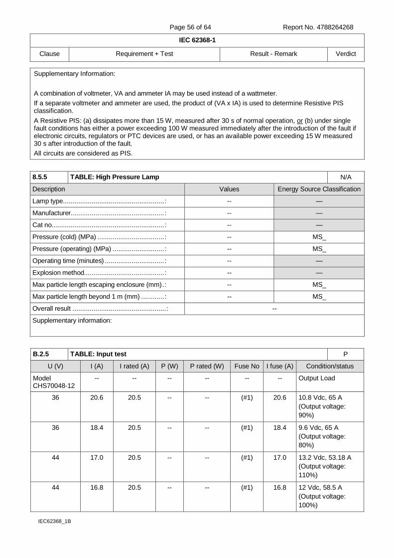
Page 56 of 64 Report No. 4788264268
IEC 62368-1
Clause Requirement + Test Result - Remark Verdict
IEC62368_1B
Supplementary Information:
A combination of voltmeter, VA and ammeter IA may be used instead of a wattmeter.
If a separate voltmeter and ammeter are used, the product of (VA x IA) is used to determine Resistive PIS classification.
A Resistive PIS: (a) dissipates more than 15 W, measured after 30 s of normal operation, or (b) under single fault conditions has either a power exceeding 100 W measured immediately after the introduction of the fault if electronic circuits, regulators or PTC devices are used, or has an available power exceeding 15 W measured 30 s after introduction of the fault.
All circuits are considered as PIS.
8.5.5 TABLE: High Pressure Lamp N/A
Description Values Energy Source Classification
Lamp type ..................................................... : -- —
Manufacturer................................................. : -- —
Cat no. .......................................................... : -- —
Pressure (cold) (MPa) ................................... : -- MS_
Pressure (operating) (MPa) ........................... : -- MS_
Operating time (minutes) ............................... : -- —
Explosion method.......................................... : -- —
Max particle length escaping enclosure (mm) . : -- MS_
Max particle length beyond 1 m (mm) ............ : -- MS_
Overall result ................................................. : --
Supplementary information:
B.2.5 TABLE: Input test P
U (V) I (A) I rated (A) P (W) P rated (W) Fuse No I fuse (A) Condition/status
Model CHS70048-12
-- -- -- -- -- -- Output Load
36 20.6 20.5 -- -- (#1) 20.6 10.8 Vdc, 65 A
(Output voltage:
90%)
36 18.4 20.5 -- -- (#1) 18.4 9.6 Vdc, 65 A
(Output voltage:
80%)
44 17.0 20.5 -- -- (#1) 17.0 13.2 Vdc, 53.18 A
(Output voltage:
110%)
44 16.8 20.5 -- -- (#1) 16.8 12 Vdc, 58.5 A
(Output voltage:
100%)
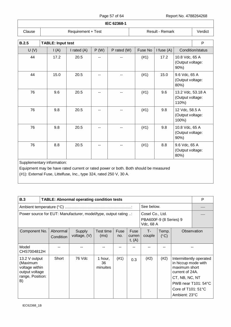
Page 57 of 64 Report No. 4788264268
IEC 62368-1
Clause Requirement + Test Result - Remark Verdict
IEC62368_1B
B.2.5 TABLE: Input test P
U (V) I (A) I rated (A) P (W) P rated (W) Fuse No I fuse (A) Condition/status
44 17.2 20.5 -- -- (#1) 17.2 10.8 Vdc, 65 A
(Output voltage:
90%)
44 15.0 20.5 -- -- (#1) 15.0 9.6 Vdc, 65 A
(Output voltage:
80%)
76 9.6 20.5 -- -- (#1) 9.6 13.2 Vdc, 53.18 A
(Output voltage:
110%)
76 9.8 20.5 -- -- (#1) 9.8 12 Vdc, 58.5 A
(Output voltage:
100%)
76 9.8 20.5 -- -- (#1) 9.8 10.8 Vdc, 65 A
(Output voltage:
90%)
76 8.8 20.5 -- -- (#1) 8.8 9.6 Vdc, 65 A
(Output voltage:
80%)
Supplementary information:
Equipment may be have rated current or rated power or both. Both should be measured
(#1): External Fuse, Littelfuse, Inc., type 324, rated 250 V, 30 A.
B.3 TABLE: Abnormal operating condition tests P
Ambient temperature (C) ........................................................... : See below.
Power source for EUT: Manufacturer, model/type, output rating .. : Cosel Co., Ltd.
PBA600F-9 (8 Series) 9 Vdc, 68 A
Component No. Abnormal
Condition
Supply voltage, (V)
Test time (ms)
Fuse no.
Fuse current, (A)
T-couple
Temp.
(C)
Observation
Model CHS7004812H
-- -- -- -- -- -- -- --
13.2 V output (Maximum voltage within output voltage range, Position: B)
Short 76 Vdc 1 hour, 36
minuites
(#1) 0.3 (#2) (#2) Intermittently operated in hiccup mode with maximum short current of 24A.
CT, NB, NC, NT
PWB near T101: 54°C
Core of T101: 51°C
Ambient: 23°C
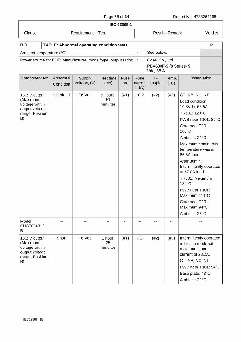
Page 58 of 64 Report No. 4788264268
IEC 62368-1
Clause Requirement + Test Result - Remark Verdict
IEC62368_1B
B.3 TABLE: Abnormal operating condition tests P
Ambient temperature (C) ........................................................... : See below.
Power source for EUT: Manufacturer, model/type, output rating .. : Cosel Co., Ltd.
PBA600F-9 (8 Series) 9 Vdc, 68 A
Component No. Abnormal
Condition
Supply voltage, (V)
Test time (ms)
Fuse no.
Fuse current, (A)
T-couple
Temp.
(C)
Observation
13.2 V output (Maximum voltage within output voltage range, Position: B)
Overload 76 Vdc 5 hours, 51
minuites
(#1) 10.2 (#2) (#2) CT, NB, NC, NT
Load condition:
10.8Vdc, 66.5A
TR501: 123°C
PWB near T101: 89°C
Core near T101:
108°C
Ambient: 24°C
Maximum continuous
temperature was at
66.5A load.
After 30min.
Intermittently operated
at 67.0A load.
TR501: Maximum
132°C
PWB near T101:
Maximum 114°C
Core near T101:
Maximum 94°C
Ambient: 25°C
Model CHS7004812H-B
-- -- -- -- -- -- -- --
13.2 V output (Maximum voltage within output voltage range, Position: B)
Short 76 Vdc 1 hour, 25
minuites
(#1) 0.2 (#2) (#2) Intermittently operated
in hiccup mode with
maximum short
current of 23.2A.
CT, NB, NC, NT
PWB near T101: 54°C
Base plate: 43°C
Ambient: 22°C

Page 59 of 64 Report No. 4788264268
IEC 62368-1
Clause Requirement + Test Result - Remark Verdict
IEC62368_1B
B.3 TABLE: Abnormal operating condition tests P
Ambient temperature (C) ........................................................... : See below.
Power source for EUT: Manufacturer, model/type, output rating .. : Cosel Co., Ltd.
PBA600F-9 (8 Series) 9 Vdc, 68 A
Component No. Abnormal
Condition
Supply voltage, (V)
Test time (ms)
Fuse no.
Fuse current, (A)
T-couple
Temp.
(C)
Observation
13.2 V output (Maximum voltage within output voltage range, Position: B)
Overload 76 Vdc 2 hours, 51
minuites
(#1) 10.4 (#2) (#2) CT, NB, NC, NT
Load condition:
10.8Vdc, 68A
PWB near T101:
128°C
Base plate: 116 °C
Ambient: 21 °C
Maximum continuous
temperature was at
68A load.
After 10min.
Intermittently operated
at 68.5A load.
PWB near T101:
Maximum 130°C
Base plate: Maximum
118°C.
Ambient: 25°C
Supplementary information: Test table is provided to record abnormal and fault conditions for all applicable energy sources including Thermal burn injury. Column “Abnormal/Fault.” Specify if test condition by indicating “Abnormal” then the condition for a Clause B.3 test or “Single Fault” then the condition for Clause B.4.
IP - Internal protection operated (list component)
CD - Components damaged (list damaged components)
CT - Constant temperatures were obtained
NB - No indication of dielectric breakdown
NC - Cheesecloth remained intact
NT - Tissue paper remained intact
(#1): External Fuse, Littelfuse, Inc., type 324, rated 250V, 30A.
(#2): See appended table 5.4.1.4, 6.3.2, 9.0, B.2.6.
Note: Based on the measurement result of Electrical power sources (PS) measurements for classification, the test was carried out by adjusting the output voltage to 10.8 Vdc, the maximum current and power was measured.
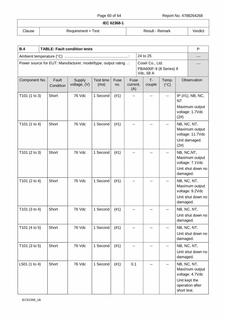
Page 60 of 64 Report No. 4788264268
IEC 62368-1
Clause Requirement + Test Result - Remark Verdict
IEC62368_1B
B.4 TABLE: Fault condition tests P
Ambient temperature (C) .......................................................... : 24 to 25
Power source for EUT: Manufacturer, model/type, output rating . : Cosel Co., Ltd.
PBA600F-9 (8 Series) 9 Vdc, 68 A
Component No. Fault
Condition
Supply voltage, (V)
Test time (ms)
Fuse no.
Fuse current,
(A)
T-couple
Temp.
(C)
Observation
T101 (1 to 3) Short 76 Vdc 1 Second (#1) -- -- -- IP (#1), NB, NC,
NT
Maximum output
voltage: 1.7Vdc
(2#)
T101 (1 to 4) Short 76 Vdc 1 Second (#1) -- -- -- NB, NC, NT,
Maximum output
voltage: 11.7Vdc
Unit damaged.
(2#)
T101 (2 to 3) Short 76 Vdc 1 Second (#1) -- -- -- NB, NC,NT,
Maximum output
voltage: 7.1Vdc
Unit shut down no
damaged.
T101 (2 to 4) Short 76 Vdc 1 Second (#1) -- -- -- NB, NC, NT,
Maximum output
voltage: 9.2Vdc
Unit shut down no
damaged.
T101 (3 to 4) Short 76 Vdc 1 Second (#1) -- -- -- NB, NC, NT,
Unit shut down no
damaged.
T101 (4 to 5) Short 76 Vdc 1 Second (#1) -- -- -- NB, NC, NT,
Unit shut down no
damaged.
T101 (3 to 5) Short 76 Vdc 1 Second (#1) -- -- -- NB, NC, NT,
Unit shut down no
damaged.
L501 (1 to 4) Short 76 Vdc 1 Second (#1) 0.1 -- -- NB, NC, NT,
Maximum output
voltage: 4.7Vdc
Unit kept the
operation after
short test.

Page 61 of 64 Report No. 4788264268
IEC 62368-1
Clause Requirement + Test Result - Remark Verdict
IEC62368_1B
PC311 input
side
Short 76 Vdc 1 Second (#1) -- -- -- NB, NC, NT,
Maximum output
voltage: 0.15Vdc
Unit shut down no
damaged.
PC311 output
side
Short 76 Vdc 1 Second (#1) -- -- -- NB, NC, NT,
Maximum output
voltage: 14.2Vdc
Unit shut down no
damaged.
PC851 input
side
Short 76 Vdc 1 Second (#1) -- -- -- NB, NC, NT,
Maximum output
voltage: 12.9Vdc
Unit shut down no
damaged.
PC851 output
side
Short 76 Vdc 15
minuites
(#1) 0.2
-- -- NB, NC, NT,
Maximum output
voltage: 13.2Vdc
Unit operated
normal.
TR103 (D to S) Short 76 Vdc 1 Second (#1) -- -- -- NB, NC, NT,
Unit shut down no
damaged.
TR103 (D to G) Short 76 Vdc 1 Second (#1) -- -- -- IP (#1), NB, NC,
NT, CD (TR103),
(2#)
C105 Short 76 Vdc 1 Second (#1) -- -- -- IP (#1), NB, NC,
NT,(2#)
IC401 (4, 7 to
10, 14)
Short 76 Vdc 15
minuites
(#1) 9.8 -- -- NB, NC, NT
Unit operated
normal.
Supplementary information: IP - Internal protection operated (list component)
CD - Components damaged (list damaged components)
CT - Constant temperatures were obtained
NB - No indication of dielectric breakdown
NC - Cheesecloth remained intact
NT - Tissue paper remained intact
(#1): External Fuse, Littelfuse, Inc., type 324, rated 250V, 30A.
This fuse is not certified by IEC.
(#2): Test was conducted three times.
Note: In consideration of Classification of electrical energy sources, the test was carried out by adjusting the maximum output voltage to 13.2 Vdc.
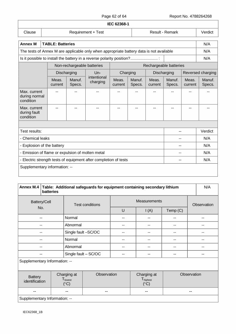
Page 62 of 64 Report No. 4788264268
IEC 62368-1
Clause Requirement + Test Result - Remark Verdict
IEC62368_1B
Annex M TABLE: Batteries N/A
The tests of Annex M are applicable only when appropriate battery data is not available N/A
Is it possible to install the battery in a reverse polarity position? ........................ : N/A
Non-rechargeable batteries Rechargeable batteries
Discharging Un-intentional charging
Charging Discharging Reversed charging
Meas. current
Manuf. Specs.
Meas. current
Manuf. Specs.
Meas. current
Manuf. Specs.
Meas. current
Manuf. Specs.
Max. current during normal condition
-- -- -- -- -- -- -- -- --
Max. current during fault condition
-- -- -- -- -- -- -- -- --
Test results: -- Verdict
- Chemical leaks -- N/A
- Explosion of the battery -- N/A
- Emission of flame or expulsion of molten metal -- N/A
- Electric strength tests of equipment after completion of tests -- N/A
Supplementary information: --
Battery identification
Charging at Tlowest
(C)
Observation Charging at Thighest
(C)
Observation
-- -- -- -- --
Supplementary Information: --
Annex M.4 Table: Additional safeguards for equipment containing secondary lithium batteries
N/A
Battery/Cell
No. Test conditions
Measurements Observation
U I (A) Temp (C)
-- Normal -- -- -- --
-- Abnormal -- -- -- --
-- Single fault –SC/OC -- -- -- --
-- Normal -- -- -- --
-- Abnormal -- -- -- --
-- Single fault – SC/OC -- -- -- --
Supplementary Information: --
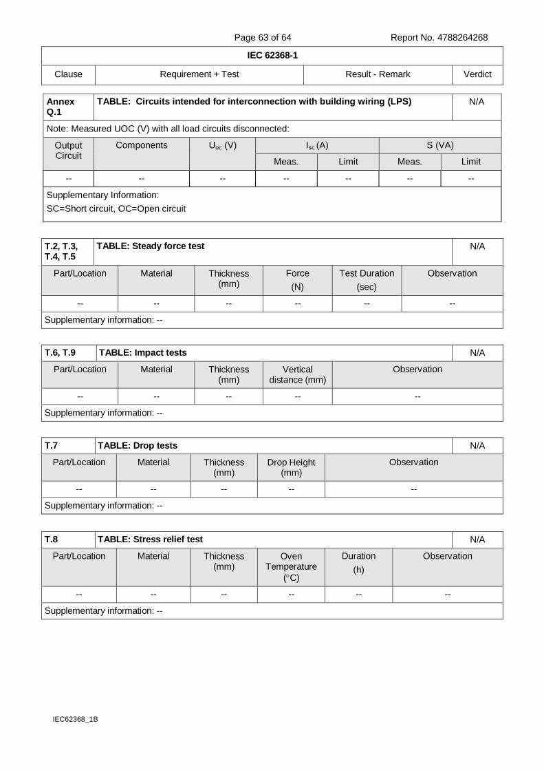
Page 63 of 64 Report No. 4788264268
IEC 62368-1
Clause Requirement + Test Result - Remark Verdict
IEC62368_1B
Annex Q.1
TABLE: Circuits intended for interconnection with building wiring (LPS) N/A
Note: Measured UOC (V) with all load circuits disconnected:
Output Circuit
Components Uoc (V) Isc (A) S (VA)
Meas. Limit Meas. Limit
-- -- -- -- -- -- --
Supplementary Information:
SC=Short circuit, OC=Open circuit
T.2, T.3, T.4, T.5
TABLE: Steady force test N/A
Part/Location Material Thickness (mm)
Force
(N)
Test Duration
(sec)
Observation
-- -- -- -- -- --
Supplementary information: --
T.6, T.9 TABLE: Impact tests N/A
Part/Location Material Thickness (mm)
Vertical distance (mm)
Observation
-- -- -- -- --
Supplementary information: --
T.7 TABLE: Drop tests N/A
Part/Location Material Thickness (mm)
Drop Height (mm)
Observation
-- -- -- -- --
Supplementary information: --
T.8 TABLE: Stress relief test N/A
Part/Location Material Thickness (mm)
Oven Temperature
(C)
Duration
(h)
Observation
-- -- -- -- -- --
Supplementary information: --
Page 64 of 64 Report No. 4788264268
List of test equipment used:
A completed list of used test equipment shall be provided in the Test Reports when a Manufacturer Testing Laboratory according to TMP/CTF stage 1 or WMT/CTF stage 2 procedure has been used.
Clause Measurement / testing
Testing / measuring equipment / material used
Range used Calibration date
-- -- -- -- --
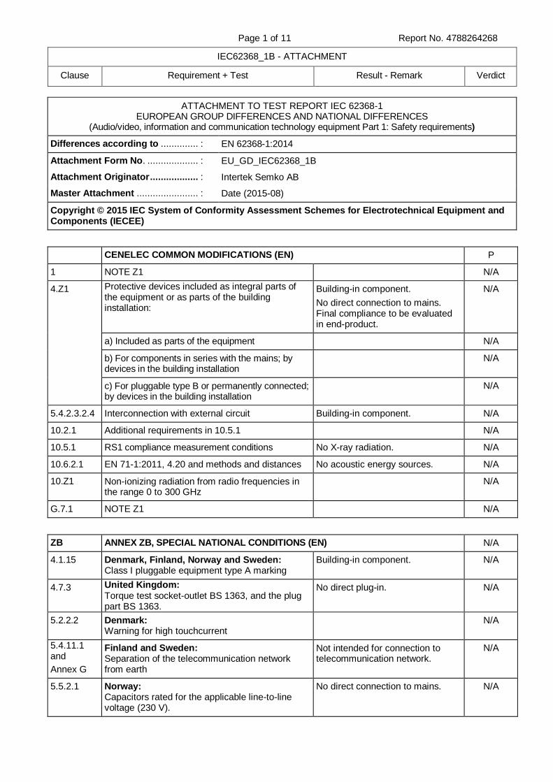
Page 1 of 11 Report No. 4788264268
IEC62368_1B - ATTACHMENT
Clause Requirement + Test Result - Remark Verdict
ATTACHMENT TO TEST REPORT IEC 62368-1 EUROPEAN GROUP DIFFERENCES AND NATIONAL DIFFERENCES
(Audio/video, information and communication technology equipment Part 1: Safety requirements)
Differences according to .............. : EN 62368-1:2014
Attachment Form No. ................... : EU_GD_IEC62368_1B
Attachment Originator .................. : Intertek Semko AB
Master Attachment ....................... : Date (2015-08)
Copyright © 2015 IEC System of Conformity Assessment Schemes for Electrotechnical Equipment and Components (IECEE)
CENELEC COMMON MODIFICATIONS (EN) P
1 NOTE Z1 N/A
4.Z1 Protective devices included as integral parts of the equipment or as parts of the building installation:
Building-in component.
No direct connection to mains. Final compliance to be evaluated in end-product.
N/A
a) Included as parts of the equipment N/A
b) For components in series with the mains; by devices in the building installation
N/A
c) For pluggable type B or permanently connected; by devices in the building installation
N/A
5.4.2.3.2.4 Interconnection with external circuit Building-in component. N/A
10.2.1 Additional requirements in 10.5.1 N/A
10.5.1 RS1 compliance measurement conditions No X-ray radiation. N/A
10.6.2.1 EN 71-1:2011, 4.20 and methods and distances No acoustic energy sources. N/A
10.Z1 Non-ionizing radiation from radio frequencies in the range 0 to 300 GHz
N/A
G.7.1 NOTE Z1 N/A
ZB ANNEX ZB, SPECIAL NATIONAL CONDITIONS (EN) N/A
4.1.15 Denmark, Finland, Norway and Sweden: Class I pluggable equipment type A marking
Building-in component. N/A
4.7.3 United Kingdom: Torque test socket-outlet BS 1363, and the plug part BS 1363.
No direct plug-in. N/A
5.2.2.2 Denmark: Warning for high touchcurrent
N/A
5.4.11.1 and
Annex G
Finland and Sweden: Separation of the telecommunication network from earth
Not intended for connection to telecommunication network.
N/A
5.5.2.1 Norway: Capacitors rated for the applicable line-to-line voltage (230 V).
No direct connection to mains. N/A
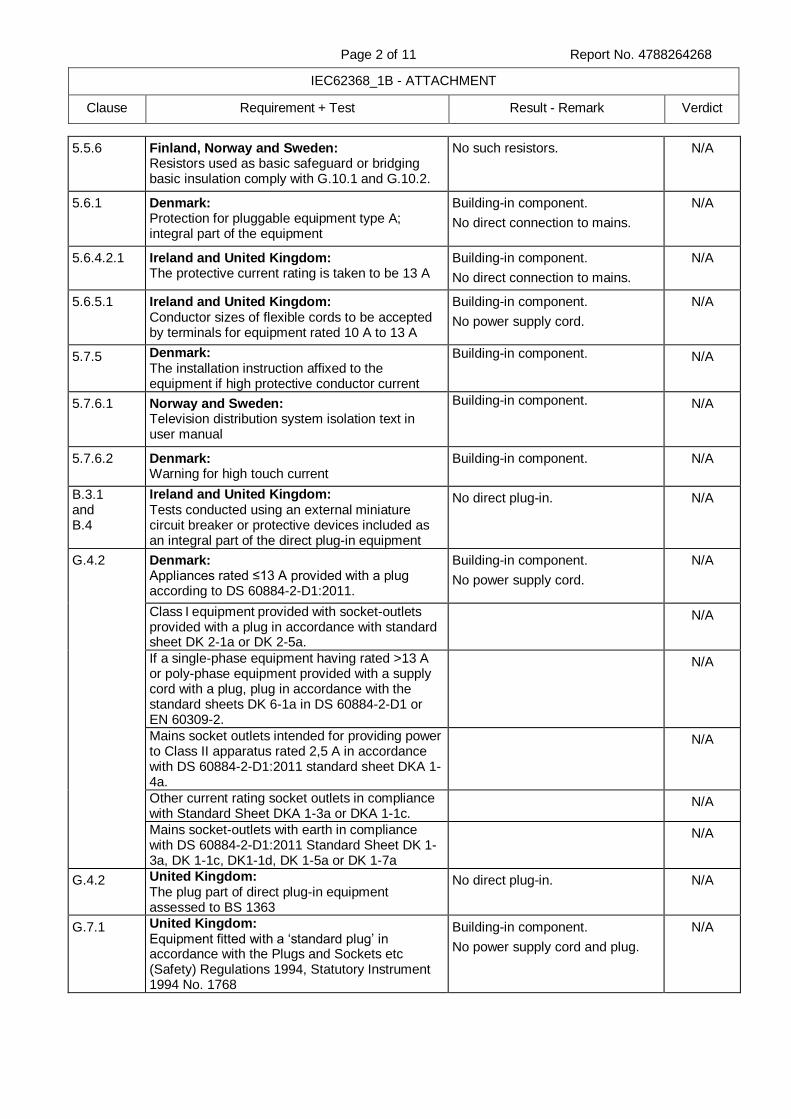
Page 2 of 11 Report No. 4788264268
IEC62368_1B - ATTACHMENT
Clause Requirement + Test Result - Remark Verdict
5.5.6 Finland, Norway and Sweden: Resistors used as basic safeguard or bridging basic insulation comply with G.10.1 and G.10.2.
No such resistors. N/A
5.6.1 Denmark: Protection for pluggable equipment type A; integral part of the equipment
Building-in component.
No direct connection to mains.
N/A
5.6.4.2.1 Ireland and United Kingdom: The protective current rating is taken to be 13 A
Building-in component.
No direct connection to mains.
N/A
5.6.5.1 Ireland and United Kingdom: Conductor sizes of flexible cords to be accepted by terminals for equipment rated 10 A to 13 A
Building-in component.
No power supply cord.
N/A
5.7.5 Denmark: The installation instruction affixed to the equipment if high protective conductor current
Building-in component. N/A
5.7.6.1 Norway and Sweden: Television distribution system isolation text in user manual
Building-in component. N/A
5.7.6.2 Denmark: Warning for high touch current
Building-in component. N/A
B.3.1 and B.4
Ireland and United Kingdom: Tests conducted using an external miniature circuit breaker or protective devices included as an integral part of the direct plug-in equipment
No direct plug-in. N/A
G.4.2 Denmark: Appliances rated ≤13 A provided with a plug according to DS 60884-2-D1:2011.
Building-in component.
No power supply cord.
N/A
Class I equipment provided with socket-outlets provided with a plug in accordance with standard sheet DK 2-1a or DK 2-5a.
N/A
If a single-phase equipment having rated >13 A or poly-phase equipment provided with a supply cord with a plug, plug in accordance with the standard sheets DK 6-1a in DS 60884-2-D1 or EN 60309-2.
N/A
Mains socket outlets intended for providing power to Class II apparatus rated 2,5 A in accordance with DS 60884-2-D1:2011 standard sheet DKA 1-4a.
N/A
Other current rating socket outlets in compliance with Standard Sheet DKA 1-3a or DKA 1-1c.
N/A
Mains socket-outlets with earth in compliance with DS 60884-2-D1:2011 Standard Sheet DK 1-3a, DK 1-1c, DK1-1d, DK 1-5a or DK 1-7a
N/A
G.4.2 United Kingdom: The plug part of direct plug-in equipment assessed to BS 1363
No direct plug-in. N/A
G.7.1 United Kingdom: Equipment fitted with a ‘standard plug’ in accordance with the Plugs and Sockets etc (Safety) Regulations 1994, Statutory Instrument 1994 No. 1768
Building-in component.
No power supply cord and plug.
N/A
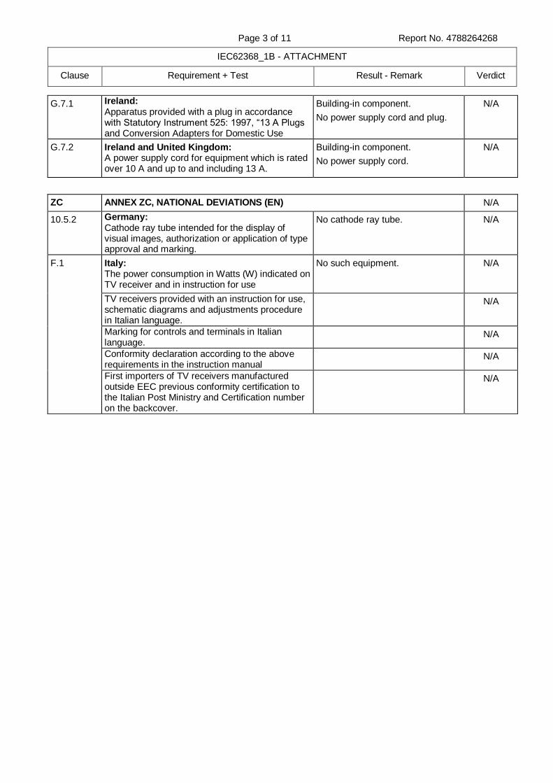
Page 3 of 11 Report No. 4788264268
IEC62368_1B - ATTACHMENT
Clause Requirement + Test Result - Remark Verdict
G.7.1 Ireland: Apparatus provided with a plug in accordance with Statutory Instrument 525: 1997, “13 A Plugs and Conversion Adapters for Domestic Use
Building-in component.
No power supply cord and plug.
N/A
G.7.2 Ireland and United Kingdom: A power supply cord for equipment which is rated over 10 A and up to and including 13 A.
Building-in component.
No power supply cord.
N/A
ZC ANNEX ZC, NATIONAL DEVIATIONS (EN) N/A
10.5.2 Germany: Cathode ray tube intended for the display of visual images, authorization or application of type approval and marking.
No cathode ray tube. N/A
F.1 Italy: The power consumption in Watts (W) indicated on TV receiver and in instruction for use
No such equipment. N/A
TV receivers provided with an instruction for use, schematic diagrams and adjustments procedure in Italian language.
N/A
Marking for controls and terminals in Italian language.
N/A
Conformity declaration according to the above requirements in the instruction manual
N/A
First importers of TV receivers manufactured outside EEC previous conformity certification to the Italian Post Ministry and Certification number on the backcover.
N/A
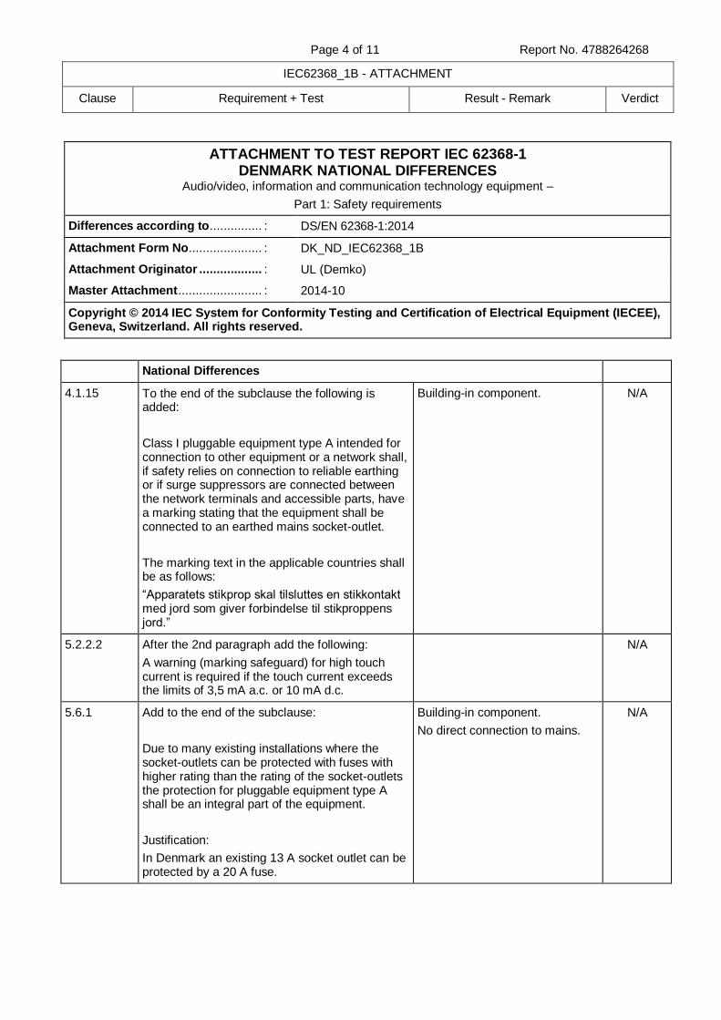
Page 4 of 11 Report No. 4788264268
IEC62368_1B - ATTACHMENT
Clause Requirement + Test Result - Remark Verdict
ATTACHMENT TO TEST REPORT IEC 62368-1 DENMARK NATIONAL DIFFERENCES
Audio/video, information and communication technology equipment –
Part 1: Safety requirements
Differences according to ............... : DS/EN 62368-1:2014
Attachment Form No. .................... : DK_ND_IEC62368_1B
Attachment Originator .................. : UL (Demko)
Master Attachment ........................ : 2014-10
Copyright © 2014 IEC System for Conformity Testing and Certification of Electrical Equipment (IECEE), Geneva, Switzerland. All rights reserved.
National Differences
4.1.15 To the end of the subclause the following is added:
Class I pluggable equipment type A intended for connection to other equipment or a network shall, if safety relies on connection to reliable earthing or if surge suppressors are connected between the network terminals and accessible parts, have a marking stating that the equipment shall be connected to an earthed mains socket-outlet.
The marking text in the applicable countries shall be as follows:
“Apparatets stikprop skal tilsluttes en stikkontakt med jord som giver forbindelse til stikproppens jord.”
Building-in component. N/A
5.2.2.2 After the 2nd paragraph add the following:
A warning (marking safeguard) for high touch current is required if the touch current exceeds the limits of 3,5 mA a.c. or 10 mA d.c.
N/A
5.6.1 Add to the end of the subclause:
Due to many existing installations where the socket-outlets can be protected with fuses with higher rating than the rating of the socket-outlets the protection for pluggable equipment type A shall be an integral part of the equipment.
Justification:
In Denmark an existing 13 A socket outlet can be protected by a 20 A fuse.
Building-in component.
No direct connection to mains.
N/A
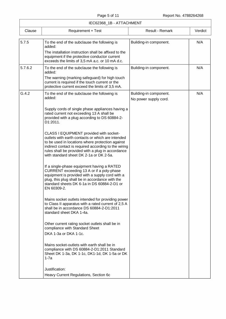
Page 5 of 11 Report No. 4788264268
IEC62368_1B - ATTACHMENT
Clause Requirement + Test Result - Remark Verdict
5.7.5 To the end of the subclause the following is added:
The installation instruction shall be affixed to the equipment if the protective conductor current exceeds the limits of 3,5 mA a.c. or 10 mA d.c.
Building-in component. N/A
5.7.6.2 To the end of the subclause the following is added:
The warning (marking safeguard) for high touch current is required if the touch current or the protective current exceed the limits of 3,5 mA.
Building-in component. N/A
G.4.2 To the end of the subclause the following is added:
Supply cords of single phase appliances having a rated current not exceeding 13 A shall be provided with a plug according to DS 60884-2-D1:2011.
CLASS I EQUIPMENT provided with socket-outlets with earth contacts or which are intended to be used in locations where protection against indirect contact is required according to the wiring rules shall be provided with a plug in accordance with standard sheet DK 2-1a or DK 2-5a.
If a single-phase equipment having a RATED CURRENT exceeding 13 A or if a poly-phase equipment is provided with a supply cord with a plug, this plug shall be in accordance with the standard sheets DK 6-1a in DS 60884-2-D1 or EN 60309-2.
Mains socket outlets intended for providing power to Class II apparatus with a rated current of 2,5 A shall be in accordance DS 60884-2-D1:2011 standard sheet DKA 1-4a.
Other current rating socket outlets shall be in compliance with Standard Sheet
DKA 1-3a or DKA 1-1c.
Mains socket-outlets with earth shall be in compliance with DS 60884-2-D1:2011 Standard Sheet DK 1-3a, DK 1-1c, DK1-1d, DK 1-5a or DK 1-7a
Justification:
Heavy Current Regulations, Section 6c
Building-in component.
No power supply cord.
N/A
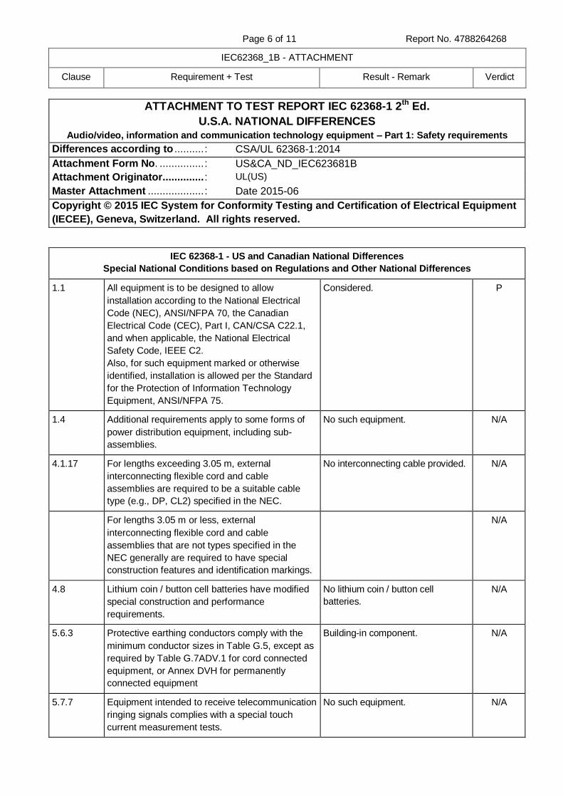
Page 6 of 11 Report No. 4788264268
IEC62368_1B - ATTACHMENT
Clause Requirement + Test Result - Remark Verdict
ATTACHMENT TO TEST REPORT IEC 62368-1 2th Ed.
U.S.A. NATIONAL DIFFERENCES
Audio/video, information and communication technology equipment – Part 1: Safety requirements
Differences according to .......... : CSA/UL 62368-1:2014
Attachment Form No. ............... : US&CA_ND_IEC623681B
Attachment Originator.............. : UL(US)
Master Attachment ................... : Date 2015-06
Copyright © 2015 IEC System for Conformity Testing and Certification of Electrical Equipment
(IECEE), Geneva, Switzerland. All rights reserved.
IEC 62368-1 - US and Canadian National Differences
Special National Conditions based on Regulations and Other National Differences
1.1 All equipment is to be designed to allow
installation according to the National Electrical
Code (NEC), ANSI/NFPA 70, the Canadian
Electrical Code (CEC), Part I, CAN/CSA C22.1,
and when applicable, the National Electrical
Safety Code, IEEE C2.
Also, for such equipment marked or otherwise
identified, installation is allowed per the Standard
for the Protection of Information Technology
Equipment, ANSI/NFPA 75.
Considered. P
1.4 Additional requirements apply to some forms of
power distribution equipment, including sub-
assemblies.
No such equipment. N/A
4.1.17 For lengths exceeding 3.05 m, external
interconnecting flexible cord and cable
assemblies are required to be a suitable cable
type (e.g., DP, CL2) specified in the NEC.
No interconnecting cable provided. N/A
For lengths 3.05 m or less, external
interconnecting flexible cord and cable
assemblies that are not types specified in the
NEC generally are required to have special
construction features and identification markings.
N/A
4.8 Lithium coin / button cell batteries have modified
special construction and performance
requirements.
No lithium coin / button cell
batteries.
N/A
5.6.3 Protective earthing conductors comply with the
minimum conductor sizes in Table G.5, except as
required by Table G.7ADV.1 for cord connected
equipment, or Annex DVH for permanently
connected equipment
Building-in component. N/A
5.7.7 Equipment intended to receive telecommunication
ringing signals complies with a special touch
current measurement tests.
No such equipment. N/A
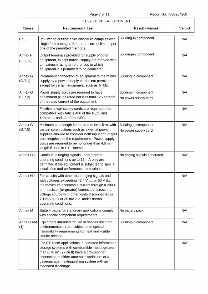
Page 7 of 11 Report No. 4788264268
IEC62368_1B - ATTACHMENT
Clause Requirement + Test Result - Remark Verdict
6.5.1 PS3 wiring outside a fire enclosure complies with
single fault testing in B.4, or be current limited per
one of the permitted methods.
Building-in component. N/A
Annex F
(F.3.3.8)
Output terminals provided for supply of other
equipment, except mains, supply are marked with
a maximum rating or references to which
equipment it is permitted to be connected.
Building-in component. N/A
Annex G
(G.7.1)
Permanent connection of equipment to the mains
supply by a power supply cord is not permitted,
except for certain equipment, such as ATMs.
Building-in component. N/A
Annex G
(G.7.3)
Power supply cords are required to have
attachment plugs rated not less than 125 percent
of the rated current of the equipment.
Building-in component.
No power supply cord.
N/A
Flexible power supply cords are required to be
compatible with Article 400 of the NEC, and
Tables 11 and 12 of the CEC.
N/A
Annex G
(G.7.5)
Minimum cord length is required to be 1.5 m, with
certain constructions such as external power
supplies allowed to consider both input and output
cord lengths into the requirement. Power supply
cords are required to be no longer than 4.5 m in
length if used in ITE Rooms.
Building-in component.
No power supply cord.
N/A
Annex H.2 Continuous ringing signals under normal
operating conditions up to 16 mA only are
permitted if the equipment is subjected to special
installation and performance restrictions.
No ringing signals generated. N/A
Annex H.4 For circuits with other than ringing signals and
with voltages exceeding 42.4 Vpeak or 60 V d.c.,
the maximum acceptable current through a 2000
ohm resistor (or greater) connected across the
voltage source with other loads disconnected is
7.1 mA peak or 30 mA d.c. under normal
operating conditions.
N/A
Annex M Battery packs for stationary applications comply
with special component requirements.
No battery pack. N/A
Annex DVA
(1)
Equipment intended for use in spaces used for
environmental air are subjected to special
flammability requirements for heat and visible
smoke release.
Building-in component. N/A
For ITE room applications, automated information
storage systems with combustible media greater
than 0.76 m3 (27 cu ft) have a provision for
connection of either automatic sprinklers or a
gaseous agent extinguishing system with an
extended discharge.
N/A
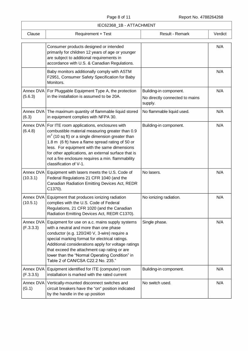
Page 8 of 11 Report No. 4788264268
IEC62368_1B - ATTACHMENT
Clause Requirement + Test Result - Remark Verdict
Consumer products designed or intended
primarily for children 12 years of age or younger
are subject to additional requirements in
accordance with U.S. & Canadian Regulations.
N/A
Baby monitors additionally comply with ASTM
F2951, Consumer Safety Specification for Baby
Monitors.
N/A
Annex DVA
(5.6.3)
For Pluggable Equipment Type A, the protection
in the installation is assumed to be 20A.
Building-in component.
No directly connected to mains
supply.
N/A
Annex DVA
(6.3)
The maximum quantity of flammable liquid stored
in equipment complies with NFPA 30.
No flammable liquid used. N/A
Annex DVA
(6.4.8)
For ITE room applications, enclosures with
combustible material measuring greater than 0.9
m2 (10 sq ft) or a single dimension greater than
1.8 m (6 ft) have a flame spread rating of 50 or
less. For equipment with the same dimensions
for other applications, an external surface that is
not a fire enclosure requires a min. flammability
classification of V-1.
Building-in component. N/A
Annex DVA
(10.3.1)
Equipment with lasers meets the U.S. Code of
Federal Regulations 21 CFR 1040 (and the
Canadian Radiation Emitting Devices Act, REDR
C1370).
No lasers. N/A
Annex DVA
(10.5.1)
Equipment that produces ionizing radiation
complies with the U.S. Code of Federal
Regulations, 21 CFR 1020 (and the Canadian
Radiation Emitting Devices Act, REDR C1370).
No ionizing radiation. N/A
Annex DVA
(F.3.3.3)
Equipment for use on a.c. mains supply systems
with a neutral and more than one phase
conductor (e.g. 120/240 V, 3-wire) require a
special marking format for electrical ratings.
Additional considerations apply for voltage ratings
that exceed the attachment cap rating or are
lower than the “Normal Operating Condition” in
Table 2 of CAN/CSA C22.2 No. 235.”
Single phase. N/A
Annex DVA
(F.3.3.5)
Equipment identified for ITE (computer) room
installation is marked with the rated current
Building-in component. N/A
Annex DVA
(G.1)
Vertically-mounted disconnect switches and
circuit breakers have the "on" position indicated
by the handle in the up position
No switch used. N/A
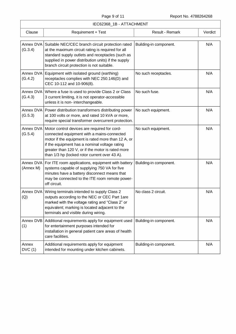
Page 9 of 11 Report No. 4788264268
IEC62368_1B - ATTACHMENT
Clause Requirement + Test Result - Remark Verdict
Annex DVA
(G.3.4)
Suitable NEC/CEC branch circuit protection rated
at the maximum circuit rating is required for all
standard supply outlets and receptacles (such as
supplied in power distribution units) if the supply
branch circuit protection is not suitable.
Building-in component. N/A
Annex DVA
(G.4.2)
Equipment with isolated ground (earthing)
receptacles complies with NEC 250.146(D) and
CEC 10-112 and 10-906(8).
No such receptacles. N/A
Annex DVA
(G.4.3)
Where a fuse is used to provide Class 2 or Class
3 current limiting, it is not operator-accessible
unless it is non- interchangeable.
No such fuse. N/A
Annex DVA
(G.5.3)
Power distribution transformers distributing power
at 100 volts or more, and rated 10 kVA or more,
require special transformer overcurrent protection.
No such equipment. N/A
Annex DVA
(G.5.4)
Motor control devices are required for cord-
connected equipment with a mains-connected
motor if the equipment is rated more than 12 A, or
if the equipment has a nominal voltage rating
greater than 120 V, or if the motor is rated more
than 1/3 hp (locked rotor current over 43 A).
No such equipment. N/A
Annex DVA
(Annex M)
For ITE room applications, equipment with battery
systems capable of supplying 750 VA for five
minutes have a battery disconnect means that
may be connected to the ITE room remote power-
off circuit.
Building-in component. N/A
Annex DVA
(Q)
Wiring terminals intended to supply Class 2
outputs according to the NEC or CEC Part 1are
marked with the voltage rating and “Class 2” or
equivalent; marking is located adjacent to the
terminals and visible during wiring.
No class 2 circuit. N/A
Annex DVB
(1)
Additional requirements apply for equipment used
for entertainment purposes intended for
installation in general patient care areas of health
care facilities.
Building-in component. N/A
Annex
DVC (1)
Additional requirements apply for equipment
intended for mounting under kitchen cabinets.
Building-in component. N/A
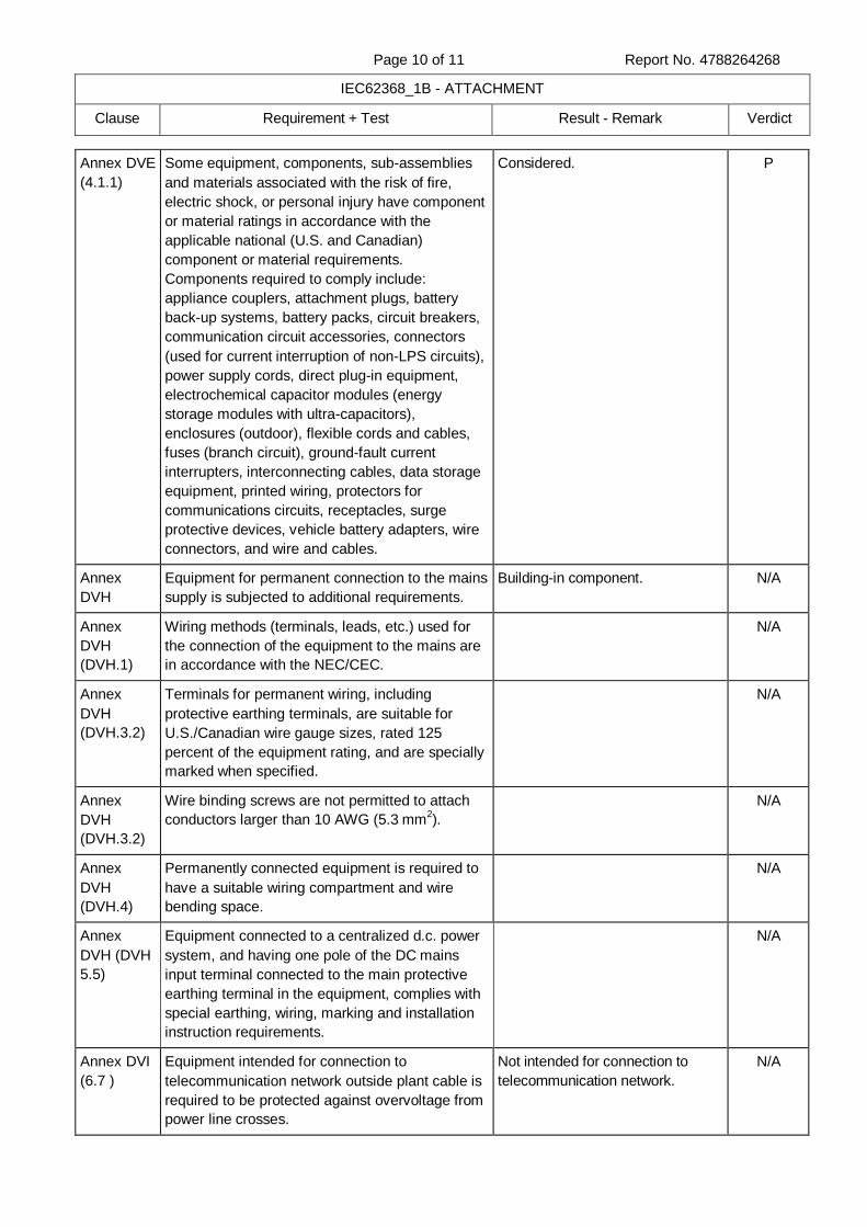
Page 10 of 11 Report No. 4788264268
IEC62368_1B - ATTACHMENT
Clause Requirement + Test Result - Remark Verdict
Annex DVE
(4.1.1)
Some equipment, components, sub-assemblies
and materials associated with the risk of fire,
electric shock, or personal injury have component
or material ratings in accordance with the
applicable national (U.S. and Canadian)
component or material requirements.
Components required to comply include:
appliance couplers, attachment plugs, battery
back-up systems, battery packs, circuit breakers,
communication circuit accessories, connectors
(used for current interruption of non-LPS circuits),
power supply cords, direct plug-in equipment,
electrochemical capacitor modules (energy
storage modules with ultra-capacitors),
enclosures (outdoor), flexible cords and cables,
fuses (branch circuit), ground-fault current
interrupters, interconnecting cables, data storage
equipment, printed wiring, protectors for
communications circuits, receptacles, surge
protective devices, vehicle battery adapters, wire
connectors, and wire and cables.
Considered. P
Annex
DVH
Equipment for permanent connection to the mains
supply is subjected to additional requirements.
Building-in component. N/A
Annex
DVH
(DVH.1)
Wiring methods (terminals, leads, etc.) used for
the connection of the equipment to the mains are
in accordance with the NEC/CEC.
N/A
Annex
DVH
(DVH.3.2)
Terminals for permanent wiring, including
protective earthing terminals, are suitable for
U.S./Canadian wire gauge sizes, rated 125
percent of the equipment rating, and are specially
marked when specified.
N/A
Annex
DVH
(DVH.3.2)
Wire binding screws are not permitted to attach
conductors larger than 10 AWG (5.3 mm2).
N/A
Annex
DVH
(DVH.4)
Permanently connected equipment is required to
have a suitable wiring compartment and wire
bending space.
N/A
Annex
DVH (DVH
5.5)
Equipment connected to a centralized d.c. power
system, and having one pole of the DC mains
input terminal connected to the main protective
earthing terminal in the equipment, complies with
special earthing, wiring, marking and installation
instruction requirements.
N/A
Annex DVI
(6.7 )
Equipment intended for connection to
telecommunication network outside plant cable is
required to be protected against overvoltage from
power line crosses.
Not intended for connection to
telecommunication network.
N/A
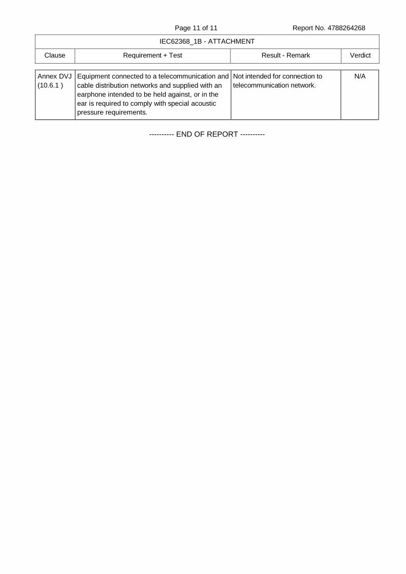
Page 11 of 11 Report No. 4788264268
IEC62368_1B - ATTACHMENT
Clause Requirement + Test Result - Remark Verdict
Annex DVJ
(10.6.1 )
Equipment connected to a telecommunication and
cable distribution networks and supplied with an
earphone intended to be held against, or in the
ear is required to comply with special acoustic
pressure requirements.
Not intended for connection to
telecommunication network.
N/A
---------- END OF REPORT ----------

Page 1 of 19 Report No. 4788264268
Enclosures
Type Supplement Id Description
Photographs 1-01 CHS7004812H - Top view
Photographs 1-02 CHS7004812H - Side view 1
Photographs 1-03 CHS7004812H - Side view 2
Photographs 1-04 CHS7004812H - Bottom view
Photographs 1-05 CHS7004812H-B - Top Side view
Photographs 1-06 CHS7004812H-B - Bottom Side view
Photographs 1-07 CHS7004812H-B - Location of Thermal conductor sheet
Schematics + PWB 2-01 Component Layout
Schematics + PWB 2-02 Trace Layout
Miscellaneous 3-01 Instruction Manual for Model CHS7004812H
Miscellaneous 3-02 Instruction Manual for Model CHS7004812H-B
Miscellaneous 3-03 Input Voltage and Output Voltage derating
Miscellaneous 3-04 Declaration of Conformity on RoHS
Miscellaneous 3-05 Manufacturer’s Declaration under IECEE CB Scheme
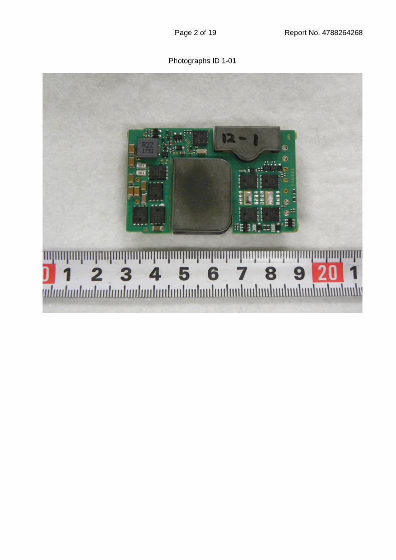
Page 2 of 19 Report No. 4788264268
Photographs ID 1-01
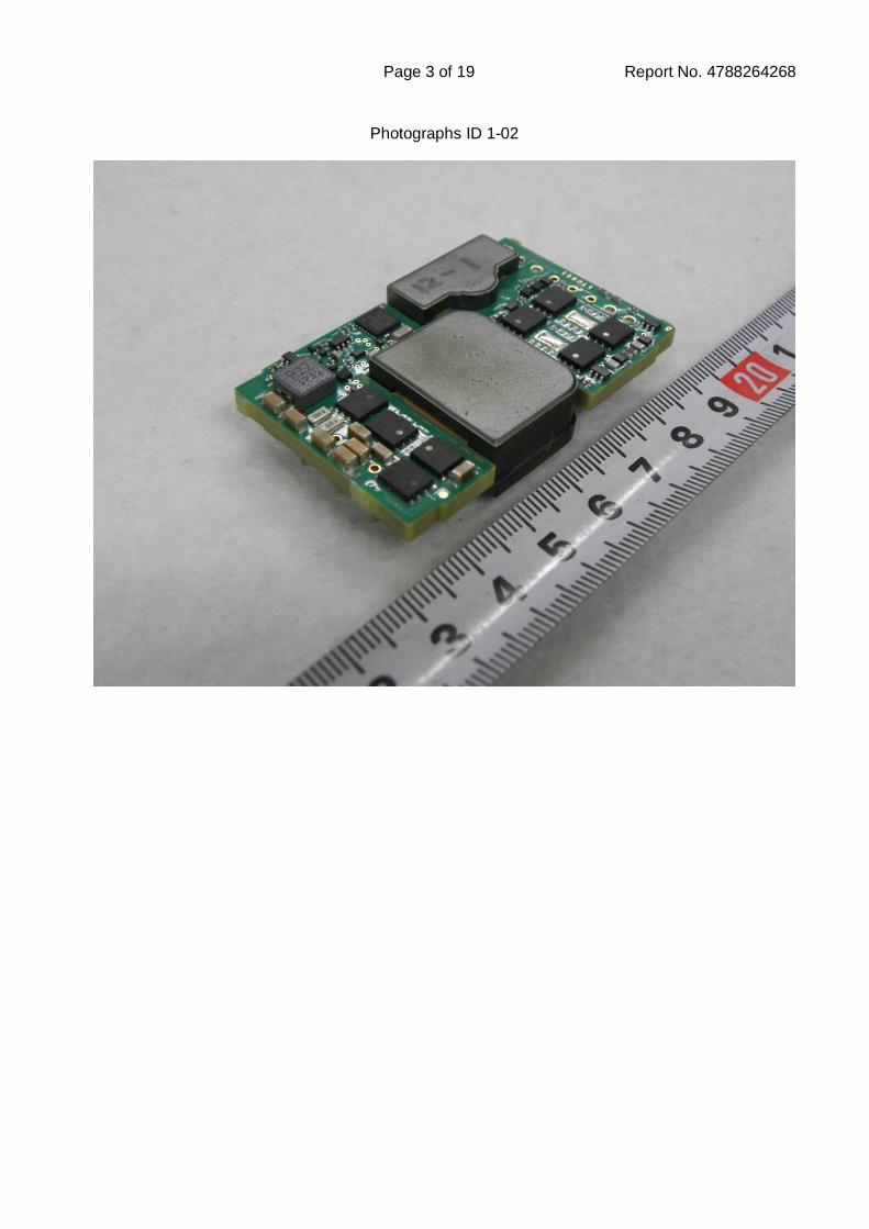
Page 3 of 19 Report No. 4788264268
Photographs ID 1-02
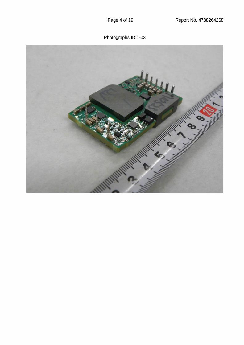
Page 4 of 19 Report No. 4788264268
Photographs ID 1-03
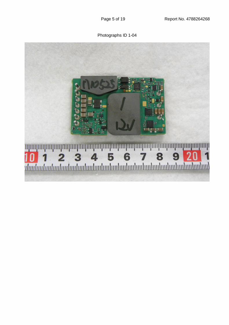
Page 5 of 19 Report No. 4788264268
Photographs ID 1-04
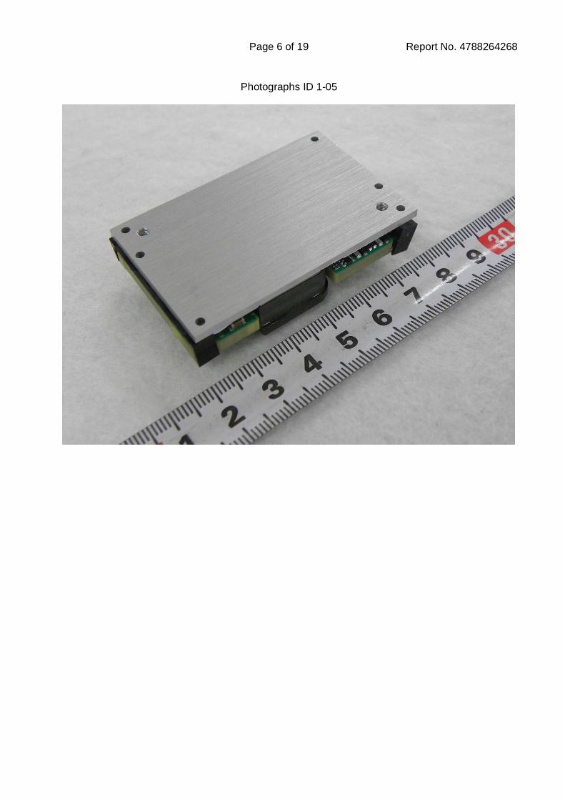
Page 6 of 19 Report No. 4788264268
Photographs ID 1-05
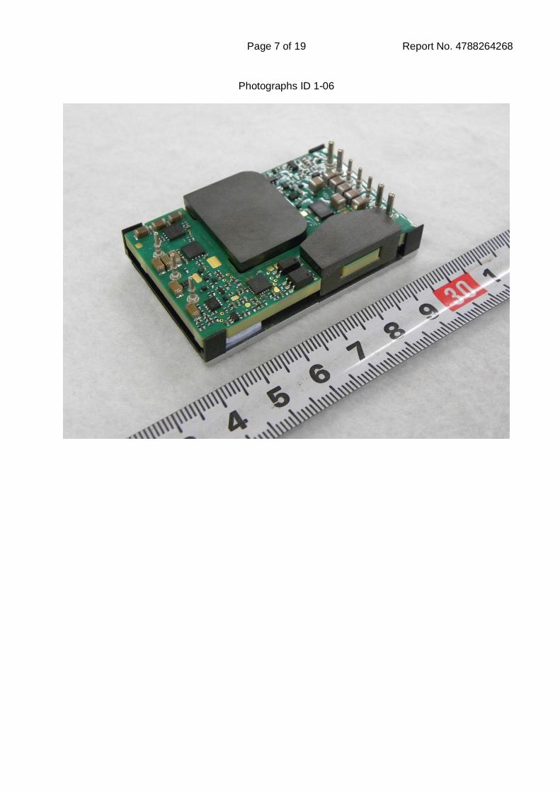
Page 7 of 19 Report No. 4788264268
Photographs ID 1-06
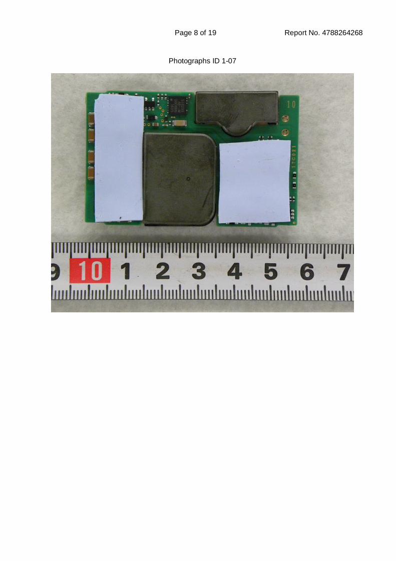
Page 8 of 19 Report No. 4788264268
Photographs ID 1-07
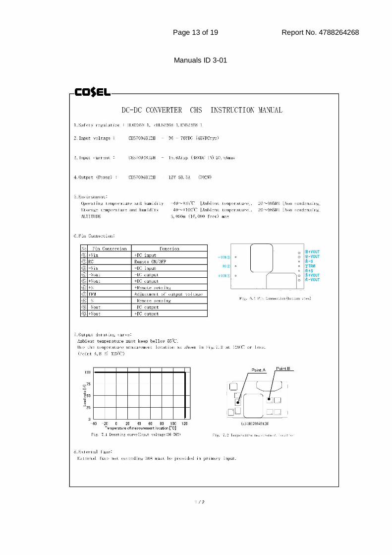
Page 13 of 19 Report No. 4788264268
Manuals ID 3-01
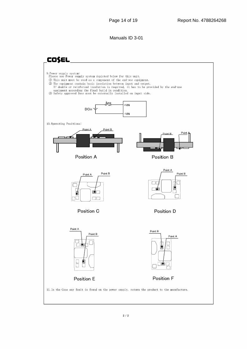
Page 14 of 19 Report No. 4788264268
Manuals ID 3-01

Page 15 of 19 Report No. 4788264268
Manuals ID 3-02
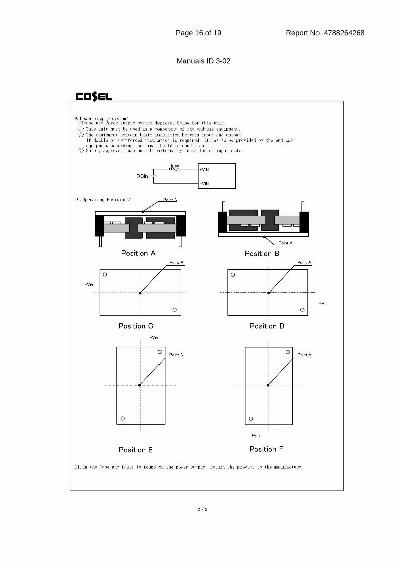
Page 16 of 19 Report No. 4788264268
Manuals ID 3-02
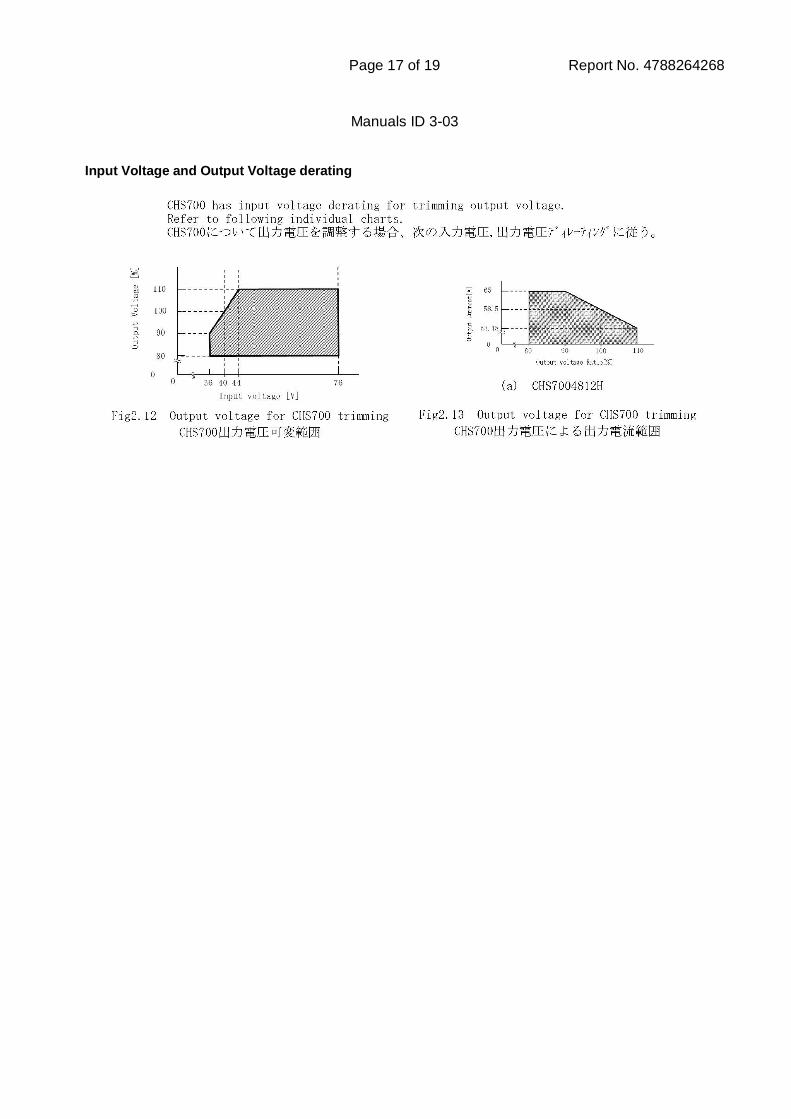
Page 17 of 19 Report No. 4788264268
Manuals ID 3-03 Input Voltage and Output Voltage derating
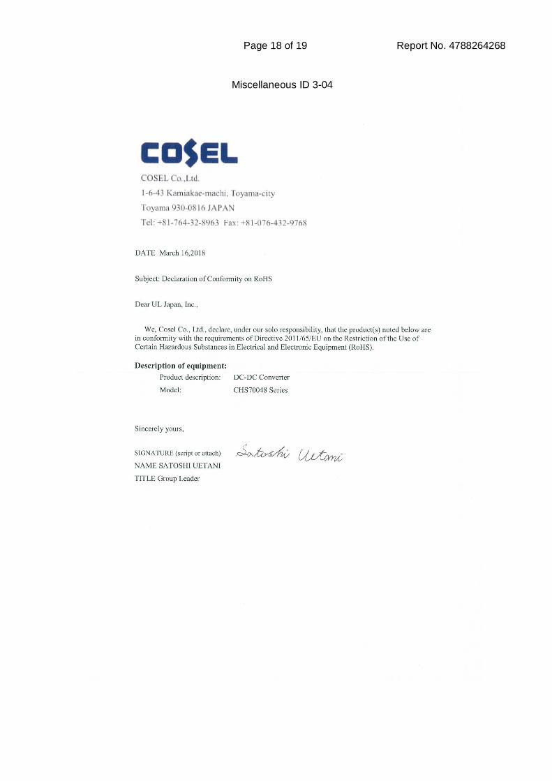
Page 18 of 19 Report No. 4788264268
Miscellaneous ID 3-04
Page 19 of 19 Report No. 4788264268
Miscellaneous ID 3-05


![SDK Design Guidelines - mouser.com · SDK Design Guidelines version 2 Z© WllÁÁÁX( }} ... Z© WllÁÁÁX]v oX }ul o v l^ < Z© Wll Á]© X }ul/v oZ o^ v Legal Information](https://img.pdfslide.us/doc/110x75/5ad89d8e7f8b9ab8378d897a/sdk-design-guidelines-design-guidelines-version-2-z-wllx-z-wllxv-ox-ul.jpg)


![Jamal ul Qurantehfizulquran.weebly.com/uploads/2/0/5/8/20589222/jamal...£ ¢ˆ V ! y Z X c − | 7 … — b ˇ Z g z Z c GM M k ‡ Û ‡ ˆł ‡Þ ł]c ð B - ˚ Z îG “GG3](https://img.pdfslide.us/doc/110x75/60d1153a7e8139483335801a/jamal-ul-v-y-z-x-c-a-7-a-b-z-g-z-z-c-gm-m-k-a-a-.jpg)