Embed Size (px)
Citation preview

GEDigital Energy
UR Series
UR 3
Upgrade GuideGE Publication Number: GET-8550GE Part Number: 1601-0050-A1Copyright © 2013 GE Multilin Inc.
This document outlines how to assess and upgrade Universal Relay (UR) versions 3.5 and below to versions 4.xx to 7.xx.
Introduction
This upgrade guide outlines the path to upgrade existing UR versions 3.5 and below hardware and firmware to UR versions 4.xx to 7.xx. In most cases, an upgrade to version 7.xx is recommended, but upgrades can be provided to version 4.xx to 6.xx if required.
This upgrade guide applies where all relay modules of the UR are recommended for replacement using a Replacement Kit. The kit consists of a set of all modules for one UR, typically including power supply, central processing unit (CPU) module, current and voltage digital signal processor (DSP) module, digital I/O modules, and transducer I/O modules. It includes equivalent modules to an existing UR version 3.5 or below Intelligent Electronic Device (IED). The kit consists of the module set for one complete UR and two labels, plus downloadable software. The case assembly, backplane, and front display are not included.
The Replacement Kit cannot contain a redundant power supply or an Ethernet switch module; a complete relay replacement is required in those cases. The reason is because a UR version 3.5 and below case assembly does not have the capability to contain either a redundant power supply or Ethernet switch module.
The process is to determine if an upgrade is required, outline the required options, order the Replacement Kit, upgrade the software, replace modules, and testing.
Determine if upgrade is required
An upgrade is recommended under the following circumstances:
• The age of the UR IED is 10 years or more
• The UR was exposed to
– High temperatures and humidity
– High electrical stresses
– Harsh environments
• Poor state of the UR
UR 3 - UPGRADE GUIDE 1

Each condition is explained as follows.
Identify age, model number, and serial numberUse the product label and the front panel or EnerVista software to determine the age, model number, and serial number. The model number is also referred to as the order code.
If the label model number, serial number, or manufacturing date differ with the front panel/EnerVista software, it indicates that the CPU was changed since manufacturing. It is recommended to use the oldest date.
View information on rear label of URThe figure shows that the model number, serial number, and manufacturing date of the UR are given on the rear label of the UR. If the rear label is missing, use the label on the inside of the front panel.
Figure 1: UR label
View information on front panel of URThe front panel allows viewing of the model number, serial number, and manufacturing date.
To view the information:
1. Press the MENU button repeatedly until the ACTUAL VALUES menu displays.
2. Press the down arrow key repeatedly until the PRODUCT INFO menu displays.
3. Press the right arrow key to display MODEL INFORMATION, then the right arrow key to display the order code.
4. Press the down arrow key to display the SERIAL NUMBER, then the MANUFACTURING DATE.
Figure 2: Front panel display
2 UR 3 - UPGRADE GUIDE

Figure 3: Settings that can be navigated in the front panel
View information in EnerVista softwareThe EnerVista software displays the model number, serial number, and manufacturing date of the UR. Navigate to Actual Values > Product Info > Model Information.
Figure 4: EnerVista display
Extreme environmental factorsDigital relay components applied in ideal environments can last over 15 years, with a shorter life in harsh environments.
Degradation of digital protection relays occurs when they are exposed to:
• High temperatures and humidity
• High electrical stresses
• Harsh environments
UR 3 - UPGRADE GUIDE 3
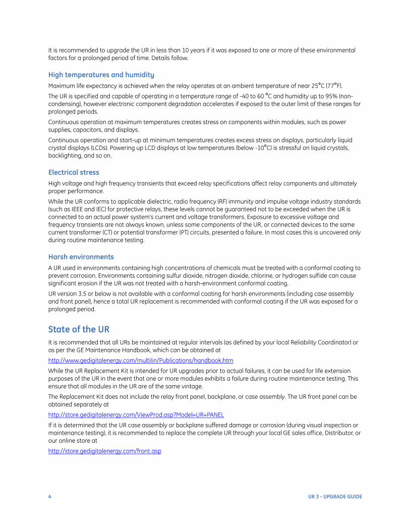
It is recommended to upgrade the UR in less than 10 years if it was exposed to one or more of these environmental factors for a prolonged period of time. Details follow.
High temperatures and humidityMaximum life expectancy is achieved when the relay operates at an ambient temperature of near 25°C (77°F).
The UR is specified and capable of operating in a temperature range of -40 to 60 °C and humidity up to 95% (non-condensing), however electronic component degradation accelerates if exposed to the outer limit of these ranges for prolonged periods.
Continuous operation at maximum temperatures creates stress on components within modules, such as power supplies, capacitors, and displays.
Continuous operation and start-up at minimum temperatures creates excess stress on displays, particularly liquid crystal displays (LCDs). Powering up LCD displays at low temperatures (below -10°C) is stressful on liquid crystals, backlighting, and so on.
Electrical stressHigh voltage and high frequency transients that exceed relay specifications affect relay components and ultimately proper performance.
While the UR conforms to applicable dielectric, radio frequency (RF) immunity and impulse voltage industry standards (such as IEEE and IEC) for protective relays, these levels cannot be guaranteed not to be exceeded when the UR is connected to an actual power system's current and voltage transformers. Exposure to excessive voltage and frequency transients are not always known, unless some components of the UR, or connected devices to the same current transformer (CT) or potential transformer (PT) circuits, presented a failure. In most cases this is uncovered only during routine maintenance testing.
Harsh environmentsA UR used in environments containing high concentrations of chemicals must be treated with a conformal coating to prevent corrosion. Environments containing sulfur dioxide, nitrogen dioxide, chlorine, or hydrogen sulfide can cause significant erosion if the UR was not treated with a harsh-environment conformal coating.
UR version 3.5 or below is not available with a conformal coating for harsh environments (including case assembly and front panel), hence a total UR replacement is recommended with conformal coating if the UR was exposed for a prolonged period.
State of the URIt is recommended that all URs be maintained at regular intervals (as defined by your local Reliability Coordinator) or as per the GE Maintenance Handbook, which can be obtained at
http://www.gedigitalenergy.com/multilin/Publications/handbook.htm
While the UR Replacement Kit is intended for UR upgrades prior to actual failures, it can be used for life extension purposes of the UR in the event that one or more modules exhibits a failure during routine maintenance testing. This ensure that all modules in the UR are of the same vintage.
The Replacement Kit does not include the relay front panel, backplane, or case assembly. The UR front panel can be obtained separately at
http://store.gedigitalenergy.com/ViewProd.asp?Model=UR+PANEL
If it is determined that the UR case assembly or backplane suffered damage or corrosion (during visual inspection or maintenance testing), it is recommended to replace the complete UR through your local GE sales office, Distributor, or our online store at
http://store.gedigitalenergy.com/front.asp
4 UR 3 - UPGRADE GUIDE
Obtain replacement kit
Once it is determined that a UR or multiple URs need to be upgraded, list the requirements and order the products.
List requirementsList the following information and requirements:
• Existing UR model and serial numbers from the back label and front panel/EnerVista software (provide both numbers if there are differences between the label and front panel/EnerVista software)
• Preferred CPU-type (if different from the recommendations that follow)
• Specific firmware required (default firmware is the latest available)
• Additional software options from order code table/list of new upgraded firmware (if required)
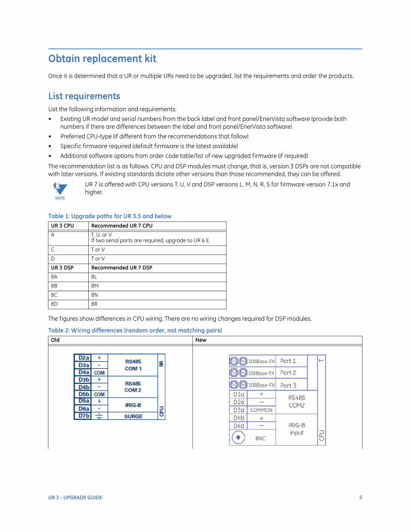
The recommendation list is as follows. CPU and DSP modules must change, that is, version 3 DSPs are not compatible with later versions. If existing standards dictate other versions than those recommended, they can be offered.
Table 1: Upgrade paths for UR 3.5 and below
The figures show differences in CPU wiring. There are no wiring changes required for DSP modules.
Table 2: Wiring differences (random order, not matching pairs)
NOTE
UR 7 is offered with CPU versions T, U, V and DSP versions L, M, N, R, S for firmware version 7.1x and higher.
UR 3 CPU Recommended UR 7 CPU
A T, U, or VIf two serial ports are required, upgrade to UR 6 E.
C T or V
D T or V
UR 3 DSP Recommended UR 7 DSP
8A 8L
8B 8M
8C 8N
8D 8R
Old New
UR 3 - UPGRADE GUIDE 5

You can use the following template to record the information required when requesting UR Replacement kits.
An example is as follows:
D60-C00-HCH-F8A-H6B-W7D with firmware 2.80 converts to
D60-T00-HCH-F8L-H6B-W7D with firmware 7.11 (recommended) with Replacement Kit
D6R-T00-HCH-F8L-H6B-W7D
Optionally, the firmware version, CPU module, and software options can be changed.
Order replacement kitContact the closest regional sales office or local distributor and provide the information, request a quote, and place the order. Contacts for the closest regional sales office or local distributor can be obtained from
http://www.gedigitalenergy.com/multilin/salesoff.htm
Old New
6 UR 3 - UPGRADE GUIDE

Upgrade EnerVista software and convert relay settings
Before converting an existing settings file, ensure that the later version of the EnerVista UR Setup software is installed. For example, if the existing UR is a D60 with firmware 3.50 and needs to be upgraded to firmware 7.1x, then use EnerVista UR Setup version 7.1x or later.
The EnerVista software can be obtained through EnerVista Launchpad; which in turn can be obtained from
http://www.gedigitalenergy.com/multilin/enervista/launchpad/
or from the GE Digital Energy website at
http://www.gedigitalenergy.com/download/download.asp?id=urfamily&file=2
If the settings file to be converted is firmware version 2.44 or below, multiple conversions can be necessary. Obtain EnerVista UR Setup version 2.4 and convert the settings file to firmware version 2.4, then upgrade to 4.6x using URsetup460.exe, and if required to 7.1x or later.
To upgrade to firmware 4.6, for firmware versions 1.8x to 4.6x, use EnerVista UR Setup 4.6 at
http://www.gedigitalenergy.com/products/software/ur/URsetup460.exe
For older versions, contact our Technical Support.
The recommended process is to perform relay settings file conversion offline and to verify all converted settings prior to uploading to the upgraded UR. Follow the steps here in converting the settings file to the new version. For this example, a D60 settings file order code D60-D00HPHF8AH6CM6DP6CUXXWXX firmware version 3.50 is converted to a D60 order code D60-T00HPHF8LH6CM6DP6CUXXWXX firmware version 7.1x using EnerVista UR Setup software version 7.1x.
To convert settings:
1. In the new EnerVista software, add an existing settings file to the Offline Window area as follows. Right-click the file in the Offline window, select the Add Existing Settings File option, and select the file to be added.
Figure 5: Save settings file
2. Duplicate the settings file and ensure the original is not lost or overwritten by right-clicking the added file and selecting the Duplicate Settings File option.
3. Rename the settings file to be converted by right-clicking the settings file and selecting the Rename Settings File option.
UR 3 - UPGRADE GUIDE 7

Figure 6: Old and new settings files
4. Convert the settings file to version 7.1x by right-clicking the settings file and selecting the Convert Settings File option. Enter the new model number/order code and firmware version as shown. Ensure that the Order Code (CPU and DSP) is valid with the firmware selected to ensure conversion. When ready, click the Convert button.
Figure 7: Convert settings file
The software converts the file and exports a list of differences, first of settings no longer available, then those set to factory defaults, then a list of new settings.
5. Save settings file conversion results as a *.txt file for future reference by clicking File > Save As and providing a name.
8 UR 3 - UPGRADE GUIDE

Figure 8: Save the conversion information
6. View and review all settings using the Protection Summary; select the Protection Summary option at the bottom of the Files entry. Compare each grouped and control element with what is wanted from the summary. Product Setup, System Setup, FlexLogic, and Inputs/Outputs have to be verified separately.
NOTE
It is possible that certain protection or control elements changed since the original release of the UR. Review the instruction manual for the release upgraded to and investigate any changes to make sure that the product performs to your requirements. Some lines in functions, such as FlexLogic, Oscillography Digital Channels, User Programmable LED Operands, Using Digital Protection, Control, or Monitoring can be set to default, and are listed.
If Modbus or DNP maps are to be used through to SCADA from the upgraded UR, these maps need to be carefully reviewed, since they most likely where changed. Change the SCADA mapping if required.
UR 3 - UPGRADE GUIDE 9
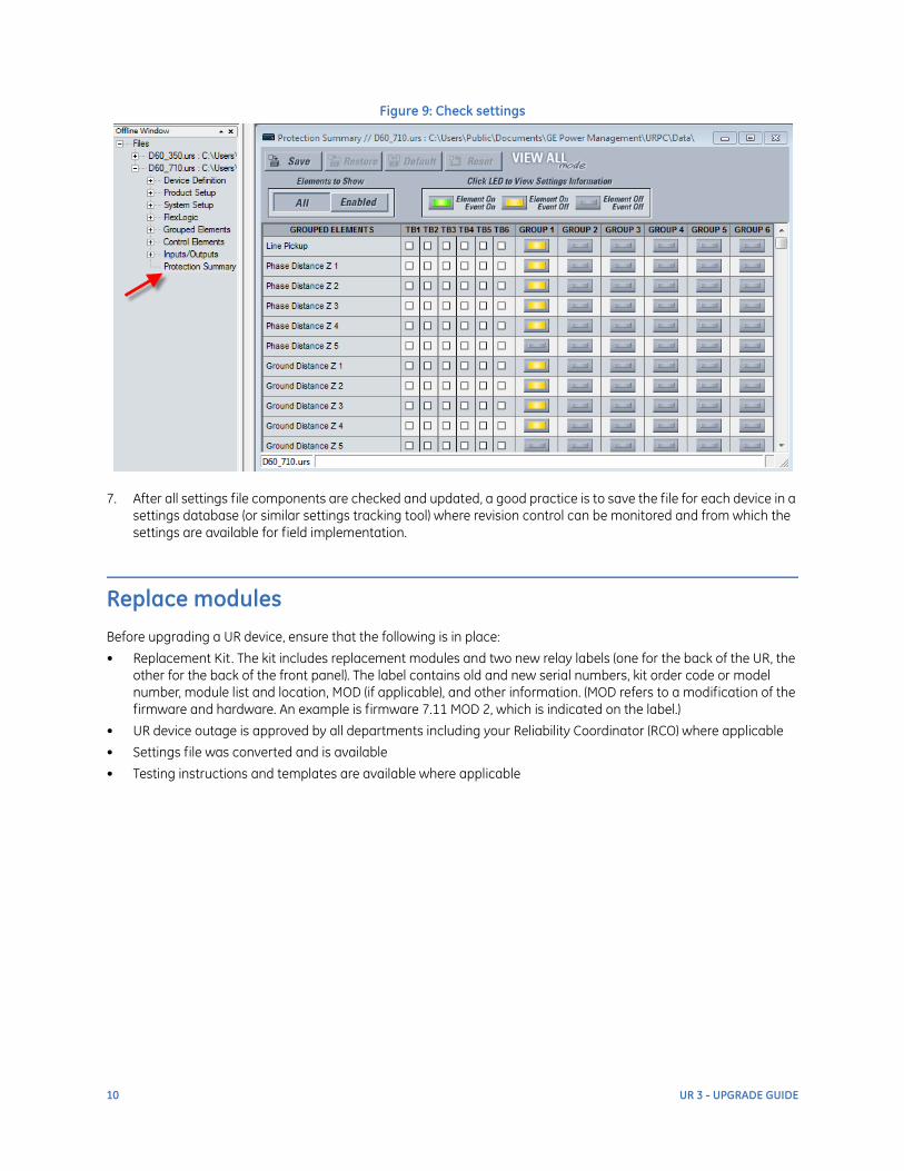
Figure 9: Check settings
7. After all settings file components are checked and updated, a good practice is to save the file for each device in a settings database (or similar settings tracking tool) where revision control can be monitored and from which the settings are available for field implementation.
Replace modules
Before upgrading a UR device, ensure that the following is in place:
• Replacement Kit. The kit includes replacement modules and two new relay labels (one for the back of the UR, the other for the back of the front panel). The label contains old and new serial numbers, kit order code or model number, module list and location, MOD (if applicable), and other information. (MOD refers to a modification of the firmware and hardware. An example is firmware 7.11 MOD 2, which is indicated on the label.)
• UR device outage is approved by all departments including your Reliability Coordinator (RCO) where applicable
• Settings file was converted and is available
• Testing instructions and templates are available where applicable
10 UR 3 - UPGRADE GUIDE

Figure 10: Replacement Kit label
To upgrade the UR:
1. Ensure that the correct UR is being approached; verify that the old relay serial number listed on the Replacement Kit corresponds to relay serial number on front display of the UR.
2. Ensure that the correct quantity and type of modules are present, for example one power supply, one CPU, same quantity DSP (CT/VT) modules, same I/O, transducer, and inter-relay communications (IRC) modules types and quantity. Compare the locations of existing modules with locations outlined on the Replacement Kit label and ensure that they are similar, for example DSP 8L in slot F compares to relay DSP 8A in slot F. If any difference in quantity or location is observed, do not commence with UR upgrade; the correct Replacement Kit needs to be obtained.
3. Connect the EnerVista software to the UR and compare existing UR settings with pre-converted settings file. If any differences, verify what and why and ensure these differences are incorporated into the converted settings file before continuing the UR upgrade. Make a backup of the UR settings if there were differences. (See the UR instruction manual if communications or EnerVista UR Setup instructions are needed.)
4. Compare converted settings file (offline) order code and firmware version with new UR order code and firmware version on the new UR labels. If there are any differences, have this corrected before commencing with UR upgrade.
5. Before powering down the UR, disable all trip outputs by opening test switches wired to trip contacts of UR. If not
Withdraw or insert a module only when control power has been removed from the unit, and be sure to insert only the correct module type into a slot, else personal injury, damage to the unit or connected equipment, or undesired operation can result.
UR 3 - UPGRADE GUIDE 11

available, verify if any test switches are available on tripping inputs and open. If none are available, determine if there are any other means to disable trip devices and disable if possible. On line differential schemes, ensure that all ends are disabled before powering down the UR.
6. Power down the UR by removing control power.
7. At the back of the UR, remove all communications and IRIG-B cables from the CPU module and communications module (if applicable). If the replacement CPU has the same copper connections terminal, then there is no need to disconnect the RS485 connection(s). Follow fiber optics safety precautions.
8. Open the front panel of the UR and disconnect the RJ45 cable from the front panel to the front of CPU module. The standard face plate can be opened to the left, once the sliding latch on the right side has been pushed up, as shown. This allows for easy accessibility of the modules for withdrawal.
Figure 11: Open front panel
9. To properly remove a module, pull simultaneously the ejector/inserter clips, located at the top and bottom of each module.
10. Replace existing UR modules with Replacement Kit modules one by one. Ensure that the correct module is used in the appropriate slot. Push the top and bottom inserter clips simultaneously when inserting a module. Replace the rear CPU terminal plate (with connections if applicable) before inserting the new CPU module if applicable. On older UR devices, insert the replacement modules with caution, ensuring that the backplane connector pins do not get bent or damaged.
11. Reconnect the RJ45 cable from front panel to front of CPU module before powering the UR up.
12. Power up the UR by applying control power.
13. Verify that the UR does not display a DSP ERROR or HARDWARE MISMATCH error. If this is the case, power down and check all replaced modules, for example that all modules are in the correct slots.
14. If modules need to be changed, with the power off, change the modules, and then power up the UR.
15. If a HARDWARE MISMATCH error is still present after it was confirmed that the correct Replacement Kit was used with correct modules inserted in the appropriate UR slots of the intended UR, follow the Update Order Code command to allow the CPU to read all modules and update the order code. (See the UR instruction manual for details.) Notify your GE sales office if this occurred.
16. Compare the Order Code from the front panel/EnerVista UR Setup with the two new UR label Order Codes. Notify your GE sales office if they do not match; the kit needs to be verified and corrected.
17. Connect the EnerVista software to the UR and check that converted settings file matches the new UR order code and upload the converted settings file if it matches. If it does not match, check that the correct kit was ordered
12 UR 3 - UPGRADE GUIDE

and that the settings file was converted to the correct expected order code. If there are discrepancies, either update the Settings File (which can need to be off-site if major) if possible, or have the Replacement Kit corrected through your GE sales office. In extreme cases (if all cannot be corrected at site), it can be necessary to back out of the upgrade and revert back to the original UR order code by re-applying the original modules.
18. If all was correct after module replacement and upload of the converted settings file, power the UR down by removing control power and apply one of the Replacement Kit UR labels to the rear of front panel and close front panel of UR.
19. Apply the second UR label to the rear of the UR over the existing label. This ensures that the correct order code and serial number are captured on the rear of the UR and the UR front panel.
20. Power up the UR by applying control power.
21. Before putting the UR in service, complete some out-of-service and in-service maintenance testing as outlined in the following section.
Perform pre-service checks and tests
A detailed test plan with test results template is recommended for the specific UR model, to ensure that all testing is executed in a controlled manner. To get started, this section outlines out-of-service and in-service maintenance steps before putting the UR in service.
In-service maintenance tests:
• Visual verification of analog value integrity, such as voltage and current. Compare metered values of the UR with that of a corresponding system or device.
• Visual verification of active alarms, relay display messages, self-test alarm messages, and LED indications
• Perform LED test. Ensure that all is operational.
• Visual inspection of UR's physical condition, noting any damage, corrosion, excessive dust, loose wires, and so on
• Compare as-is relay settings with as-left settings file. This can be done by comparing uploaded UR settings with converted settings file.
Out-of-service maintenance tests:
• Check the integrity of wiring connections, for example that they are secure
• Check analog values (currents, voltages, RTDs, analog inputs) through injection test and metering accuracy verification. Calibrated test equipment is required.
• Perform secondary injection testing of AC quantities and DC signals. Check enabled protection functions.
• Verify contact inputs and outputs. This can be done by direct change of state of forcing or as part of functional testing.
• Perform pushbutton continuity testing
If these tests show that any element of the UR is defective, contact our Technical Support team for assistance and recommendations. It is not always necessary to remove the UR from service.
Upon completion of testing, put the upgraded unit in service.
To put the UR in service:
1. Close all blocking and control switches.
UR 3 - UPGRADE GUIDE 13

For further assistance
For product support, contact the information and call center as follows:GE Digital Energy650 Markland StreetMarkham, OntarioCanada L6C 0M1Worldwide telephone: +1 905 927 7070Europe/Middle East/Africa telephone: +34 94 485 88 54North America toll-free: 1 800 547 8629Fax: +1 905 927 5098Worldwide e-mail: [email protected] e-mail: [email protected]: http://www.gedigitalenergy.com/multilin/
14 UR 3 - UPGRADE GUIDE