Embed Size (px)
Citation preview
Operating Instructions UPS
PROTECT B.
PROTECT B. 750PROTECT B. 1000 PROTECT B. 1500 PROTECT B. 2000 PROTECT B. 3000

Thank you for purchasing a PROTECT B. UPS from AEG Power Supply Systems. The following security advices are an important component of the manual and will prevent any operation errors and protect you against possible dangers. Read the manual thoroughly before you first use the appliance.
1 Notes on these Operating Instructions
Duty to Provide Information These operating instructions will help you to install and operate the Uninterruptible Power Supply (UPS), PROTECT B. 750, PROTECT B. 1000, PROTECT B. 1500, PROTECT B. 2000 or PROTECT B. 3000, all referred to as PROTECT B. in this document − safely and correctly, and for its intended purpose. These operating instructions contain important information necessary to avoid dangers during operation.
Please read these instructions carefully prior to commissioning!
These operating instructions are a composite part of PROTECT B.
The operator of this unit is obliged to communicate these operating instructions to all personnel transporting or starting up PROTECT B. or performing maintenance or any other work on the unit.
Validity These operating instructions comply with the current technical specifications of PROTECT B. at the time of publication. The contents do not constitute a subject matter of the contract, but serve for information purposes only.
Warranty and Liability Our goods and services are subject to the general conditions of supply for products of the electrical industry, and our general sales conditions. We reserve the right to alter any specifications given in these operating instructions, especially with regard to technical data and operation.
3
Claims in connection with supplied goods must be submitted within eight days of receipt, along with the packing slip. Subsequent claims cannot be considered.
The warranty does not apply for damage caused by non-compliance with these instructions (such damage also includes damaging the warranty seal). AEG will accept no liability for consequential damage. AEG will rescind all obligations such as warranty agreements, service contracts, etc. entered into by AEG and its representatives without prior notification in the event of maintenance and repair work being carried out with anything other than original AEG spare parts or spare parts purchased by AEG.
Handling PROTECT B. is designed and constructed so that all necessary steps for start-up and operation can be performed without any internal manipulation of the unit. Maintenance and repair work may only be performed by trained and qualified personnel.
Illustrations are provided to clarify and facilitate certain steps.
If danger to personnel and the unit cannot be ruled out in the case of certain work, it is highlighted accordingly by pictograms explained in Chapter 3.
Hotline If you still have questions after having read these operating instructions, please contact your dealer or our "Hotline":
Tel.: ++49 (0)180 5 234 787 Fax: ++49 (0)180 5 234 789 Internet: www.aegpss.de
Copyright No part of these operating instructions may be transmitted, reproduced and/or copied by any electronic or mechanical means without the express prior written permission of AEG.
© Copyright AEG 2006. All rights reserved.
4
Table of Contents 1 Notes on these Operating Instructions ............................3 2 System Description ..........................................................7
2.1 Overview ...................................................................7 2.2 Functionality..............................................................8
3 Safety .............................................................................10 3.1 General Safety Instructions ....................................10 3.2 Safety Instructions for PROTECT B. ......................10 3.3 Certification .............................................................14 3.4 Technical Data ........................................................15
4 Set-Up and Operation ....................................................20 4.1 Unpacking and Inspection ......................................20 4.2 Point of installation..................................................21 4.3 Connections, Operation / Display Elements ...........22
4.3.1 Front view: .......................................................22 4.3.2 Operating panel ...............................................23 4.3.3 Rear view (connections): .................................24
5 Activation...................Fehler! Textmarke nicht definiert. 5.1 Deployment.............................................................26
5.1.1 Tower (Stand alone deployment) ....................26 5.1.2 19” Rack Mount Setup.....................................28
5.2 Additional battery installation setup ........................32 5.3 Emergency Power Off (EPO) set up.......................33 5.4 Electric start-up .......................................................34
5.4.1 Connection.......................................................34 5.4.2 Configuration ...................................................35
5.5 Operation ................................................................36 5.5.1 Normal Operation ............................................36 5.5.2 Battery Operation / Autonomous Operation ....36 5.5.3 Unit Overload...................................................38 5.5.4 System Diagnosis / Battery Test .....................38
5
5.6 Interfaces and communication ................................39 5.6.1 Data line protection RJ11 and RJ45................39 5.6.2 Computer interfaces RS232 and USB.............40 5.6.3 Communication slot .........................................40 5.6.4 Shutdown and UPS management software.....40
6 Signalling and failure solution ........................................42 6.1 LED display .............................................................42 6.2 Audible Alarm Trouble Shooting: ............................44 6.3 General Fault Diagnosis and Fault Rectification.....44
7 Maintenance...................................................................46 7.1 Battery replacement ................................................47
8 Storage, Dismantling and Disposal ................................52 9 Glossary .........................................................................53
9.1 Technical terms.......................................................53
6
2 System Description
iPROTECT B. is an uninterruptible power supply(UPS) for essential loads such as PCs,workstations, servers, network components,telecommunication equipment and similardevices.
The PROTECT B. series is a compact, interactive, sinusoidaly operating USP, available with an output power rate of 750, 1000, 1500, 2000 and 3000 VA.
The design of the USP allows horizontal / lying operation (Rack/19” with 2U) and vertical / standing operation (Tower).
2.1 Overview The front of the USV provides several LEDs and four push buttons for easy configuration, control and management. The panel also informs about the state of the power in the alternating current (AC) branch, indications on net failures and the charging state of the Output of the USP. You will find two LED bars for output load and battery capacity, two state indicators (net available, battery active) and four alarm indicators (power failure, failure, battery discharged, overload). With the push button the acoustic alarm can be deactivated and the self test of the UPS will be started.
Power connectors, communication interfaces and connections for telephone and network are located on the rear of the PROTECT B. Important USV parameters and data are constantly monitored and are transmitted via USB or serial RS232 to the CompuWatch Software on the management computer. The optional SNMP adapter allows remote monitoring via SNMP connector and multi server shutdown (starting with B. 1500).
The main features of the PROTECT B. are:
♦ VI (Line Interactive) protection technology with sinusoidal output voltage
7
♦ AVR control system (automatic voltage regulation with mains operation)
♦ Micro processor control for high availability, suited for generator mode
♦ Easy extension of battery capacity using external batteries (starting with B. 1500)
♦ Advanced battery management with integrated protection against extreme discharge and overcharge
♦ Overload and short circuit proof ♦ Maintenance free, sealed lead batteries, hot
swappable (starting with B. 1500) ♦ User friendly display for optimal readability /
configuration ♦ Intelligent monitoring system with USB and RS232
interface ♦ Surge protection (RJ11 / RJ45) for ISDN, fax,
modem and network ♦ Expansion slot for extension cards SNMP / potential
free contacts (starting from B. 1500) ♦ CompuWatch software for shutdown, state report
and measurement for all popular operating systems (among others Windows, Mac, Linux)
♦ Compact design / variable deployment due to combination design as tower / rack (19” kit available optionally for all models)
2.2 Functionality The UPS is connected to a shockproof socket between the public utility's mains and the loads to be protected.
Under normal operating conditions, i.e. if PROTECT B. is supplied with mains voltage, the battery charger will ensure that the battery is always completely charged.
During this operating status, the loads connected to PROTECT B. are supplied with voltage via mains filters which
8
provide effective protection against mains voltage peaks and high-frequency faults.
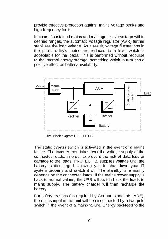
In case of sustained mains undervoltage or overvoltage within defined ranges, the automatic voltage regulator (AVR) further stabilises the load voltage. As a result, voltage fluctuations in the public utility's mains are reduced to a level which is acceptable for the loads. This is performed without recourse to the internal energy storage, something which in turn has a positive effect on battery availability.
9
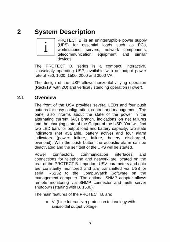
Inverter
Battery
Gleichrichter
Load
Mains Mains filter
AVR
~~
Sta
tic b
ypas
s sw
itch
Rectifier
UPS Block diagram PROTECT B.
The static bypass switch is activated in the event of a mains failure. The inverter then takes over the voltage supply of the connected loads, in order to prevent the risk of data loss or damage to the loads. PROTECT B. supplies voltage until the battery is discharged, allowing you to shut down your IT system properly and switch it off. The standby time mainly depends on the connected loads. If the mains power supply is back to normal values, the UPS will switch back the loads to mains supply. The battery charger will then recharge the battery.
For safety reasons (as required by German standards, VDE), the mains input in the unit will be disconnected by a two-pole switch in the event of a mains failure. Energy backfeed to the
mains and voltage supply to the pins of the mains connector are thus reliably avoided.
Furthermore, additional protective measures ensure effective protection for the data/network interface.
3 Safety 3.1 General Safety Instructions
Read these operating instructions carefully prior to commissioning of the PROTECT B. UPS and observe the safety instructions!
Only use the unit if it is in a technically perfect condition and always in accordance with its intended purpose, while being aware of safety and danger aspects, and in accordance with the operating instructions! Immediately eliminate any faults which could be detrimental to safety.
The following pictograms are used in these operating instructions to identify dangers and important information:
Danger! Identifies risk of fatal injury to the operator.
Attention! Identifies risk of injury and risk of damage to the unit and parts of the unit.
i
Information! Useful and important information for operating the UPS.
3.2 Safety Instructions for PROTECT B. This chapter contains important instructions for the PROTECT B. UPS. These must be followed during assembly,
10
operation and maintenance of the uninterruptible power supply and the batteries.
The UPS carries high voltage. Danger! The unit may only be opened by trained and qualifiedpersonnel. Repairs may only be carried out byqualified customer service staff!
The output may be live, even if the UPS is not connected to the mains supply, as the UPS hasits own internal power supply (battery)!
For health and safety reasons, the unit must beearthed correctly!
PROTECT B. may only be operated with or connected to a 230 VAC mains with protective grounding using a mains connection cable with PE conductor (included in the delivery) that has been tested in accordance with German standards (VDE).
Danger! Risk of burning!
The battery has powerful short-circuit currents. Incorrect connection or isolation faults can lead to melting of the plug connections, sparkingpotential and severe burns!
The unit has a warning signal that sounds whenthe battery voltage of PROTECT B. is exhausted or when the UPS is not working in its normalmode.
Observe the following safety instructions toensure permanent operational safety of and safework with the UPS:
♦ Do not dismantle the UPS! (The UPS does not contain any parts which require regular maintenance. Bear in mind that the warranty will be invalidated if the unit is opened!)
♦ Do not install the unit in direct sunshine or in close proximity of heaters!
11
♦ The unit is designed to be installed inside in heated rooms. Never install the UPS in the vicinity of water or in an excessively damp environment!
♦ Condensation may occur if the UPS is brought from a cold environment into the room where it is to be installed. The UPS must be absolutely dry prior to start-up. As a result, leave it to acclimatise for at least two hours.
♦ Never connect the mains input to the UPS output. ♦ Ensure that no fluids or foreign bodies can penetrate the
UPS! ♦ Do not block the air vents of the unit! Keep children away
from the unit and ensure that objects are never inserted through the air vents!
♦ Do not connect household appliances such as hairdryers to the UPS!
♦ The mains connection should be near the unit and easily accessible to facilitate disconnecting the AC input or pulling out the plug!
♦ During operation, do not disconnect the mains connection cable from the UPS or from the socket outlet in the building (shockproof socket), otherwise the protective grounding of the UPS and all the loads connected to it will be cancelled.
Danger! Electric shocks!
Even after the mains voltage has beendisconnected, the components within the UPSremain connected to the battery and can thuscause electric shocks. It is therefore imperative todisconnect the battery circuit before carrying outany maintenance or repair work!
If it is necessary to replace the battery or carryout maintenance work, this must be done by or under the supervision of a specialist familiar withbatteries and the necessary safety precautions!
Only authorised persons are allowed in the
12
vicinity of the batteries!
When replacing the battery/batteries, the following must be observed: Only ever use identical maintenance-free sealed lead batteries with the same data as the original battery/batteries.
Danger! Explosive!
Never throw batteries into open fire. Never open or damage batteries. (Electrolyte may leak outand damage skin and eyes. It may be toxic!)
Batteries can cause electric shocks and highshort-circuit currents.
Therefore, take the following safety precautions when working with batteries: ♦ Take off watches, rings and other metallic
objects! ♦ Only use tools with insulated handles!
For personal safety reasons, never switch on themain switch when the mains connector ofPROTECT B. is disconnected!
13
14
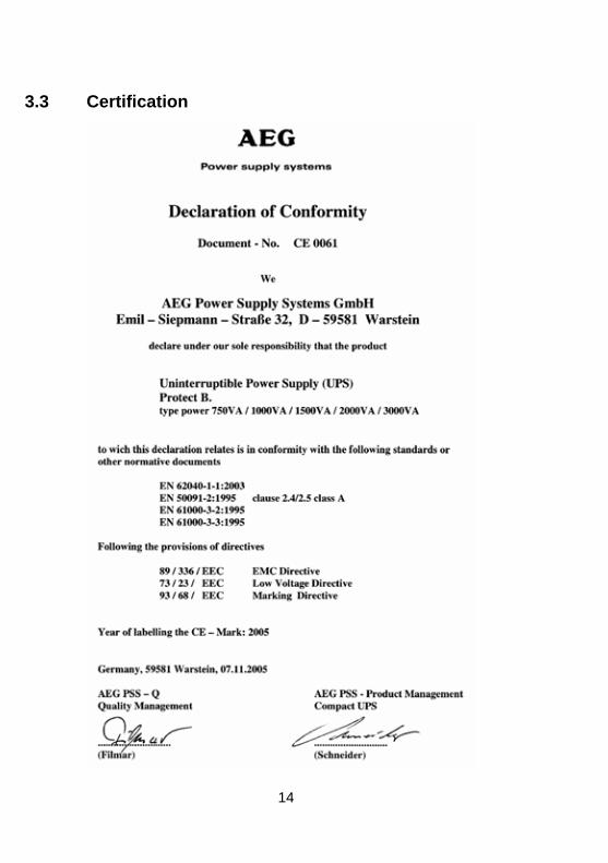
3.3 Certification
3.4 Technical Data Model power PROTECT B. 750 750 VA / 500 W PROTECT B. 1000 1000 VA / 700 W PROTECT B. 1500 1500 VA / 1050 W PROTECT B. 2000 2000 VA / 1340 W PROTECT B. 3000 3000 VA / 2100 W UPS Input
Rated output voltage 220 / 230 / 240 Vac
Input voltage range 154 / 161 / 168 Vac ± 4% (wide) 176 / 184 / 192 Vac ± 4% (standard) until 264 / 276 / 288 Vac ± 4%
Frequency (autom. detection) 50 / 60 Hz ± 5 Hz > 40 Hz (generator mode)
Curr. consumption (full-load)
PROTECT B. 750 5 A PROTECT B. 1000 8 A PROTECT B. 1500 10 A PROTECT B. 2000 10 A PROTECT B. 3000 16 A Connection IEC power connector
(IEC 320) USP output Rated output voltage / 220 / 230 / 240 Vac AVR-technology Rated output voltage in ± 5 % battery mode Frequency in battery mode 50 Hz / 60 Hz ± 0.1 Hz
15
Output current power (at 230 Vac) PROTECT B. 750 3.2 A PROTECT B. 1000 4.3 A PROTECT B. 1500 6.5 A PROTECT B. 2000 8.7 A PROTECT B. 3000 13 A Transfer time at mains outage 2-4 ms (typical), 6 ms
max. 13 ms max. in generator
operation Voltage waveform sinusoidal Outlets Non-heating appliance
connectors in acc. with IEC 320
Overload response 110% for 3 min / at mains operation 150% for 200 ms Overload response 110% for 30 s / at battery operation 120% for 100ms
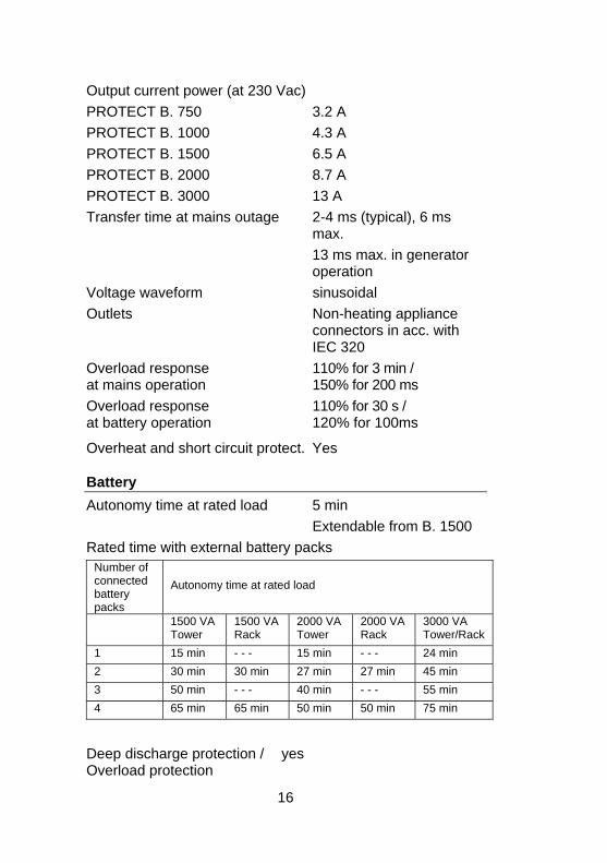
Overheat and short circuit protect. Yes Battery Autonomy time at rated load 5 min Extendable from B. 1500 Rated time with external battery packs
Number of connected battery packs
Autonomy time at rated load
1500 VA Tower
1500 VARack
2000 VA Tower
2000 VARack
3000 VA Tower/Rack
1 15 min - - - 15 min - - - 24 min 2 30 min 30 min 27 min 27 min 45 min 3 50 min - - - 40 min - - - 55 min 4 65 min 65 min 50 min 50 min 75 min
Deep discharge protection / yes Overload protection
16
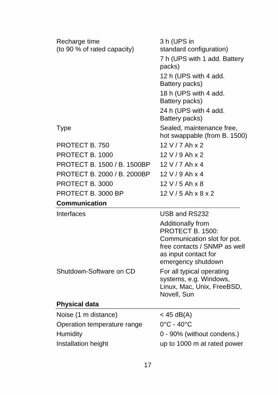
Recharge time 3 h (UPS in (to 90 % of rated capacity) standard configuration)
7 h (UPS with 1 add. Battery packs)
12 h (UPS with 4 add. Battery packs)
18 h (UPS with 4 add. Battery packs)
24 h (UPS with 4 add. Battery packs)
Type Sealed, maintenance free, hot swappable (from B. 1500)
PROTECT B. 750 12 V / 7 Ah x 2 PROTECT B. 1000 12 V / 9 Ah x 2 PROTECT B. 1500 / B. 1500BP 12 V / 7 Ah x 4 PROTECT B. 2000 / B. 2000BP 12 V / 9 Ah x 4 PROTECT B. 3000 12 V / 5 Ah x 8 PROTECT B. 3000 BP 12 V / 5 Ah x 8 x 2 Communication Interfaces USB and RS232 Additionally from
PROTECT B. 1500: Communication slot for pot. free contacts / SNMP as well as input contact for emergency shutdown
Shutdown-Software on CD For all typical operating systems, e.g. Windows, Linux, Mac, Unix, FreeBSD, Novell, Sun
Physical data Noise (1 m distance) < 45 dB(A) Operation temperature range 0°C - 40°C Humidity 0 - 90% (without condens.) Installation height up to 1000 m at rated power
17
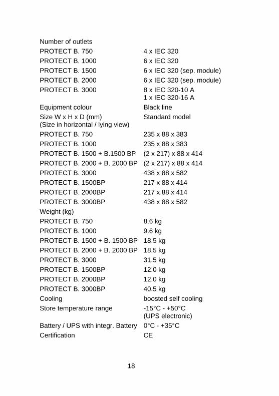
Number of outlets PROTECT B. 750 4 x IEC 320 PROTECT B. 1000 6 x IEC 320 PROTECT B. 1500 6 x IEC 320 (sep. module) PROTECT B. 2000 6 x IEC 320 (sep. module) PROTECT B. 3000 8 x IEC 320-10 A
1 x IEC 320-16 A Equipment colour Black line Size W x H x D (mm) Standard model (Size in horizontal / lying view) PROTECT B. 750 235 x 88 x 383 PROTECT B. 1000 235 x 88 x 383 PROTECT B. 1500 + B.1500 BP (2 x 217) x 88 x 414 PROTECT B. 2000 + B. 2000 BP (2 x 217) x 88 x 414 PROTECT B. 3000 438 x 88 x 582 PROTECT B. 1500BP 217 x 88 x 414 PROTECT B. 2000BP 217 x 88 x 414 PROTECT B. 3000BP 438 x 88 x 582 Weight (kg) PROTECT B. 750 8.6 kg PROTECT B. 1000 9.6 kg PROTECT B. 1500 + B. 1500 BP 18.5 kg PROTECT B. 2000 + B. 2000 BP 18.5 kg PROTECT B. 3000 31.5 kg PROTECT B. 1500BP 12.0 kg PROTECT B. 2000BP 12.0 kg PROTECT B. 3000BP 40.5 kg Cooling boosted self cooling Store temperature range -15°C - +50°C
(UPS electronic) Battery / UPS with integr. Battery 0°C - +35°C Certification CE
18
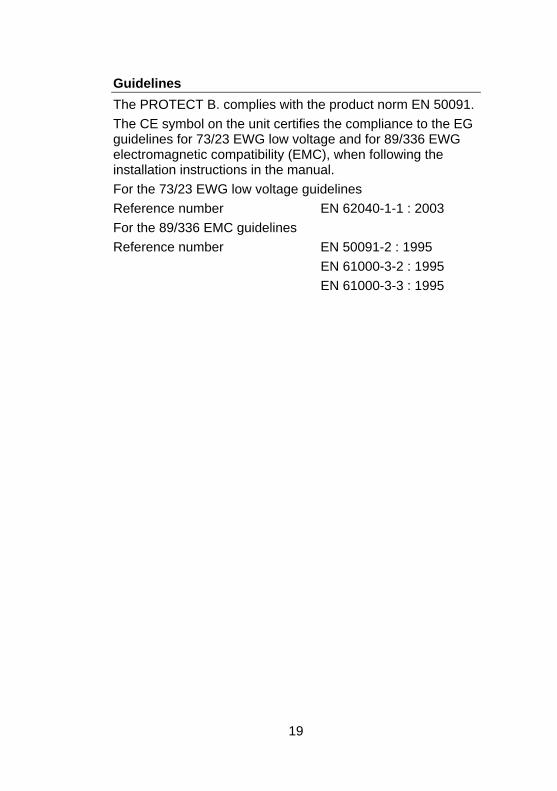
Guidelines The PROTECT B. complies with the product norm EN 50091. The CE symbol on the unit certifies the compliance to the EG guidelines for 73/23 EWG low voltage and for 89/336 EWG electromagnetic compatibility (EMC), when following the installation instructions in the manual. For the 73/23 EWG low voltage guidelines Reference number EN 62040-1-1 : 2003 For the 89/336 EMC guidelines Reference number EN 50091-2 : 1995 EN 61000-3-2 : 1995 EN 61000-3-3 : 1995
19
4 Set-Up and Operation 4.1 Unpacking and Inspection
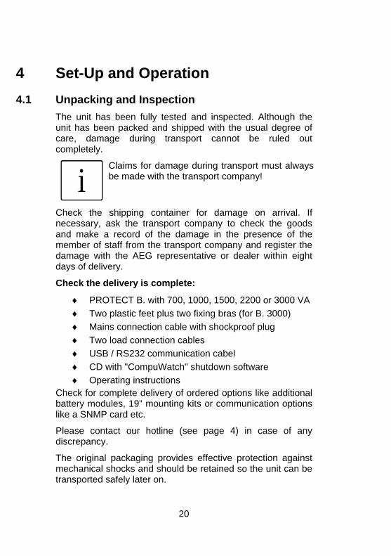
The unit has been fully tested and inspected. Although the unit has been packed and shipped with the usual degree of care, damage during transport cannot be ruled out completely.
i
Claims for damage during transport must alwaysbe made with the transport company!
Check the shipping container for damage on arrival. If necessary, ask the transport company to check the goods and make a record of the damage in the presence of the member of staff from the transport company and register the damage with the AEG representative or dealer within eight days of delivery.
Check the delivery is complete:
♦ PROTECT B. with 700, 1000, 1500, 2200 or 3000 VA ♦ Two plastic feet plus two fixing bras (for B. 3000) ♦ Mains connection cable with shockproof plug ♦ Two load connection cables ♦ USB / RS232 communication cabel ♦ CD with "CompuWatch" shutdown software ♦ Operating instructions
Check for complete delivery of ordered options like additional battery modules, 19” mounting kits or communication options like a SNMP card etc.
Please contact our hotline (see page 4) in case of any discrepancy.
The original packaging provides effective protection against mechanical shocks and should be retained so the unit can be transported safely later on.
20
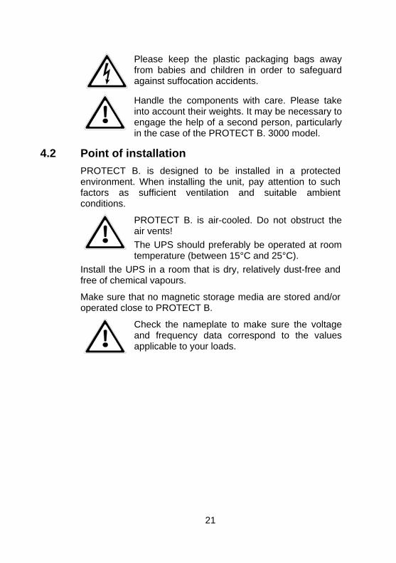
Please keep the plastic packaging bags away from babies and children in order to safeguardagainst suffocation accidents.
Handle the components with care. Please takeinto account their weights. It may be necessary to engage the help of a second person, particularly in the case of the PROTECT B. 3000 model.
4.2 Point of installation PROTECT B. is designed to be installed in a protected environment. When installing the unit, pay attention to such factors as sufficient ventilation and suitable ambient conditions.
PROTECT B. is air-cooled. Do not obstruct the air vents! The UPS should preferably be operated at room temperature (between 15°C and 25°C).
Install the UPS in a room that is dry, relatively dust-free and free of chemical vapours.
Make sure that no magnetic storage media are stored and/or operated close to PROTECT B.
Check the nameplate to make sure the voltageand frequency data correspond to the valuesapplicable to your loads.
21
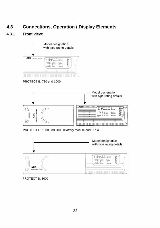
4.3 Connections, Operation / Display Elements 4.3.1 Front view:
����
����
���� ����
�� ����
�������������
��� ���
��� ���
��� ���� �������
�������
���������
��
����������
������
���������
��������
��������
���������
��
����
���!����
����
��� ���� ������� ���������
����
����
���� ����
�� ����
�������������
��� ���
��� ����������
���������
��
����������
������
���������
��������
��������
��
����
���!����
����
Model designation with type rating details
PROTECT B. 750 und 1000
Model designation with type rating details
PROTECT B. 1500 und 2000 (Battery module and UPS)
Model designation with type rating details
PROTECT B. 3000
22
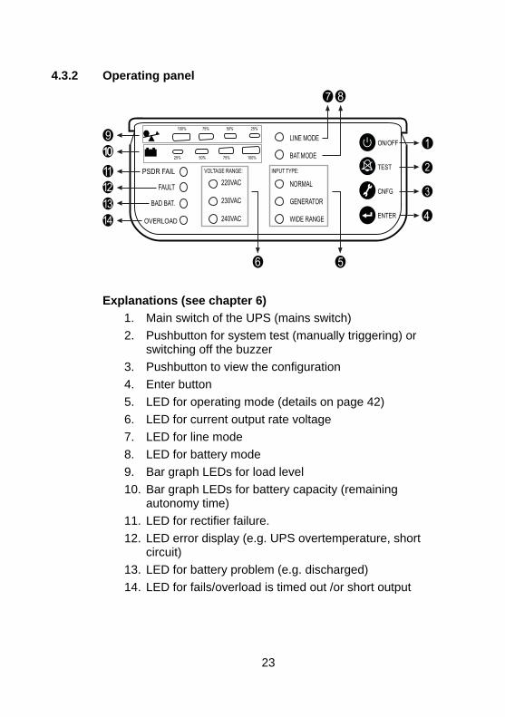
4.3.2 Operating panel
Explanations (see chapter 6)
1. Main switch of the UPS (mains switch) 2. Pushbutton for system test (manually triggering) or
switching off the buzzer 3. Pushbutton to view the configuration 4. Enter button 5. LED for operating mode (details on page 42) 6. LED for current output rate voltage 7. LED for line mode 8. LED for battery mode 9. Bar graph LEDs for load level 10. Bar graph LEDs for battery capacity (remaining
autonomy time) 11. LED for rectifier failure. 12. LED error display (e.g. UPS overtemperature, short
circuit) 13. LED for battery problem (e.g. discharged) 14. LED for fails/overload is timed out /or short output
23
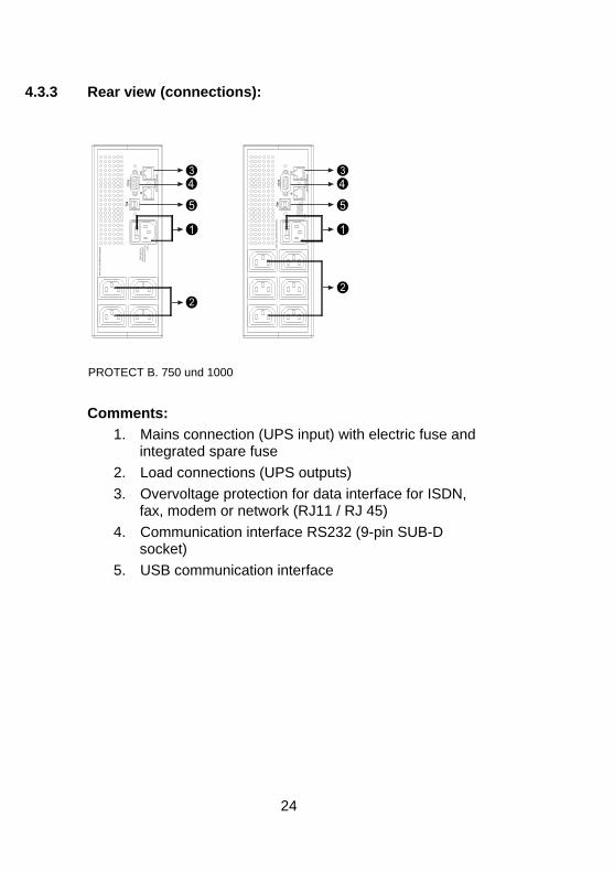
4.3.3 Rear view (connections):
Comments:
PROTECT B. 750 und 1000
1. Mains connection (UPS input) with electric fuse and integrated spare fuse
2. Load connections (UPS outputs) 3. Overvoltage protection for data interface for ISDN,
fax, modem or network (RJ11 / RJ 45) 4. Communication interface RS232 (9-pin SUB-D
socket) 5. USB communication interface
24
����
������� ���
����
�����������"
�������# �����$���%
�!������"�����������
����&����� ��!���
���'�������
������"
����
�!������"������������������# �����$���%
�
�����
�
��
������
����
�!������"�����������
�����������() ������*+���*,
����
�-!�./!�.-0���)���12
�-!�./!�.-0�������12 �3!�4!�540���)���12
�������������������!��� �
���6����#6��
$������712�!��./83/�%
��������������
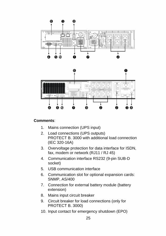
Comments:
1. Mains connection (UPS input) 2. Load connections (UPS outputs)
PROTECT B. 3000 with additional load connection (IEC 320-16A)
3. Overvoltage protection for data interface for ISDN, fax, modem or network (RJ11 / RJ 45)
4. Communication interface RS232 (9-pin SUB-D socket)
5. USB communication interface 6. Communication slot for optional expansion cards:
SNMP, AS/400 7. Connection for external battery module (battery
extension) 8. Mains input circuit breaker 9. Circuit breaker for load connections (only for
PROTECT B. 3000) 10. Input contact for emergency shutdown (EPO)
25
5 Commissioning 5.1 Deployment
The UPS was constructed for both horizontal / flat (rack/19") operation and vertical / standing (tower) operation.
Operation the unit for longer time above an ambient temperature of 25° C reduces the lifetime of the batteries.
Position the UPS unit at least 20 cm away of any other electronic equipment to prevent interference.
After deployment and assembly of the UPS follow the steps for activation as explained in chapter 5.4
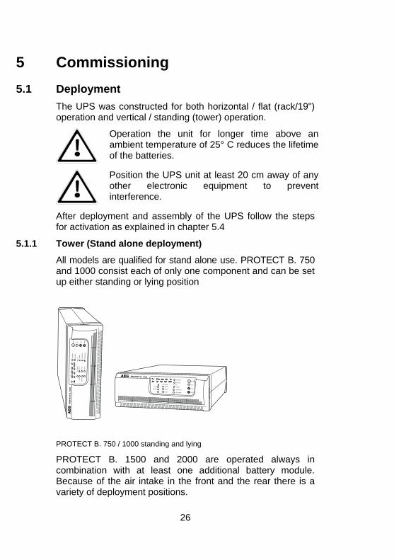
5.1.1 Tower (Stand alone deployment)
All models are qualified for stand alone use. PROTECT B. 750 and 1000 consist each of only one component and can be set up either standing or lying position
PROTECT B. 750 / 1000 standing and lying
PROTECT B. 1500 and 2000 are operated always in combination with at least one additional battery module. Because of the air intake in the front and the rear there is a variety of deployment positions.
26
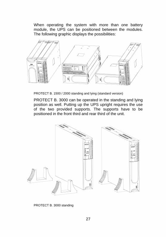
When operating the system with more than one battery module, the UPS can be positioned between the modules. The following graphic displays the possibilities:
PROTECT B. 1500 / 2000 standing and lying (standard version)
PROTECT B. 3000 can be operated in the standing and lying position as well. Putting up the UPS upright requires the use of the two provided supports. The supports have to be positioned in the front third and rear third of the unit.
PROTECT B. 3000 standing
27
Please consider for the location of setup also the guidelines on page 21 of the manual.
5.1.2 19” Rack Mount Setup
ROTECT B. 750, 1000, 1500, 2000 and 3000 can be installed in 19” racks. The UPS and external battery enclosure need 2U of valuable rack space. Mount the USP preferable in the lower third of the rack with respect to the mass centre and sufficient ventilation.
Use the optional 19” mounting kit for the installation in the rack.
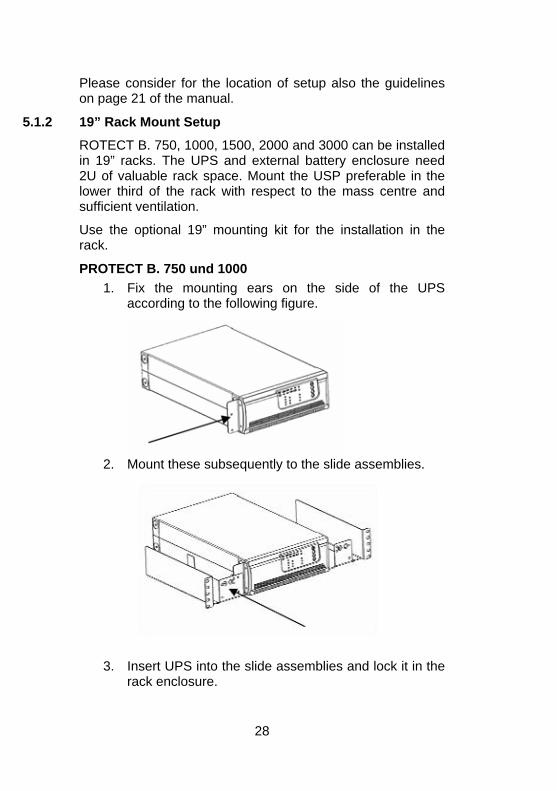
PROTECT B. 750 und 1000 1. Fix the mounting ears on the side of the UPS
according to the following figure.
2. Mount these subsequently to the slide assemblies.
3. Insert UPS into the slide assemblies and lock it in the rack enclosure.
28
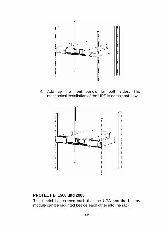
4. Add up the front panels for both sides. The mechanical installation of the UPS is completed now.
PROTECT B. 1500 und 2000 This model is designed such that the UPS and the battery module can be mounted beside each other into the rack.
29
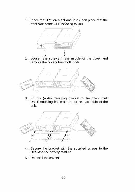
1. Place the UPS on a flat and in a clean place that the front side of the UPS is facing to you.
2. Loosen the screws in the middle of the cover and remove the covers from both units.
3. Fix the (wide) mounting bracket to the open front.
Rack mounting holes stand out on each side of the units.
4. Secure the bracket with the supplied screws to the
UPS and the battery module.
5. Reinstall the covers.
30
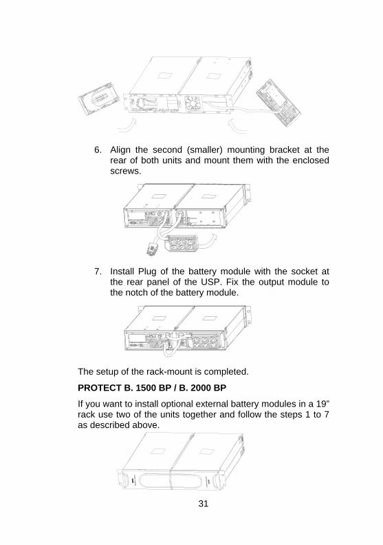
6. Align the second (smaller) mounting bracket at the
rear of both units and mount them with the enclosed screws.
7. Install Plug of the battery module with the socket at
the rear panel of the USP. Fix the output module to the notch of the battery module.
The setup of the rack-mount is completed.
PROTECT B. 1500 BP / B. 2000 BP
If you want to install optional external battery modules in a 19” rack use two of the units together and follow the steps 1 to 7 as described above.
31
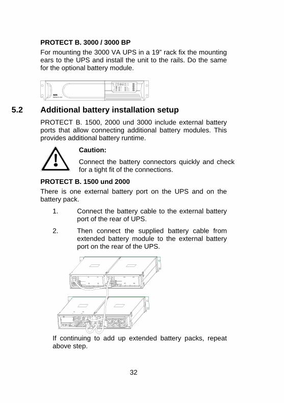
PROTECT B. 3000 / 3000 BP For mounting the 3000 VA UPS in a 19” rack fix the mounting ears to the UPS and install the unit to the rails. Do the same for the optional battery module.
����
����
���� ����
�� ����
�������������
��� ���
��� ���
��� ���� �������
�������
���������
��
����������
������
���������
��������
��������
���������
��
����
���!����
����
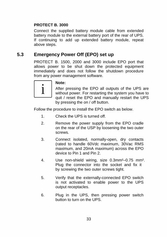
5.2 Additional battery installation setup PROTECT B. 1500, 2000 und 3000 include external battery ports that allow connecting additional battery modules. This provides additional battery runtime.
Caution:
Connect the battery connectors quickly and checkfor a tight fit of the connections.
PROTECT B. 1500 und 2000 There is one external battery port on the UPS and on the battery pack.
1. Connect the battery cable to the external battery port of the rear of UPS.
2. Then connect the supplied battery cable from extended battery module to the external battery port on the rear of the UPS.
If continuing to add up extended battery packs, repeat above step.
32
PROTECT B. 3000 Connect the supplied battery module cable from extended battery module to the external battery port of the rear of UPS. If continuing to add up extended battery module, repeat above steps.
5.3 Emergency Power Off (EPO) set up PROTECT B. 1500, 2000 and 3000 include EPO port that allows power to be shut down the protected equipment immediately and does not follow the shutdown procedure from any power management software.
i
Note: After pressing the EPO all outputs of the UPS arewithout power. For restarting the system you have toquit / reset the EPO and manually restart the UPS by pressing the on / off button.
Follow the procedure to install the EPO switch as below.
1. Check the UPS is turned off.
2. Remove the power supply from the EPO cradle on the rear of the USP by loosening the two outer screws.
3. Connect isolated, normally-open, dry contacts (rated to handle 60Vdc maximum, 30Vac RMS maximum, and 20mA maximum) across the EPO device to Pin 1 and Pin 2.
4. Use non-shield wiring, size 0.3mm²–0.75 mm². Plug the connector into the socket and fix it by screwing the two outer screws tight.
5. Verify that the externally-connected EPO switch is not activated to enable power to the UPS output receptacles.
6. Plug in the UPS, then pressing power switch button to turn on the UPS.
33
7. Activate the external EPO switch to test the EPO function
8. De-activate the external EPO switch and restart the UPS.
5.4
f
Electric start-up First compare the setting with the rated voltage valid in your country. The factory default setting is 230 V
Make any changes in accordance with the description in chapter 5.4.2 “Configuration”.
5.4.1 Connection
Now connect the input of the UPS (pos. 1 fig. p. 24/25) to the mains connection cable provided and plug the mains connector into a suitable shockproof socket.
1. Avoid using extension cables and/or adapters. In particular in the case of high-capacity types, ensure that the fusing in your sub-distribution is adequately dimensioned: The PROTECT B. 3000 for example requires its own connection with a 16 A fuse. No other loads should be connected to this circuit!
2. Then connect the outputs of your UPS (pos. 2 fig. p. 24/25) to your loads. Use the load connection cables provided for this. Don’t switch on the loads yet. Please contact your dealer if you require additional load connection cables.
3. Now switch on the UPS. To do this, press and hold the UPS main switch or about 3 seconds until the display goes on.
4. The UPS acknowledges your command by starting a self test. During this automatically running procedure a periodically audible
34
signal can be heard The green "Mains" LED is permanently illuminated when the normal operating stag has been reached (pos. 7 .p. 3). In case anything different occurs, please follow the instructions in Chapters 6.2 / 6.3.
iPlease shut down the entire system if you cannot solve any problems which occur. Please contact ourhotline (see page 4).
5. When the LINE MODE display is lit, switch on your loads one after the other. Note the maximum permitted UPS load when doing this (pos. 9 fig. p. 42).
In particular, bear in mind the considerable power consumption of loads such as laser printers, large CRT monitors and the like which can quickly lead to a UPS overload.
5.4.2 Configuration
To reconfigure the internal UPS setup options, follow the procedure as below:
1. Press the Configure button more than three seconds. Then UPS will transfer from configure mode to “output voltage mode” showing the value by a flashing LED at 220 Vac, 230 Vac or 240 Vac.
2. Press the Configure button more than one second, the UPS allows you to select the “output voltage mode” one by one.
3. After selecting the mode, press the Enter button more than three seconds, the “output voltage mode” is configured.
4. UPS will automatically transfer from configure mode to “operating mode” displayed by a flashing LED beside NORMAL, GENERATOR or WIDE RANGE.
35
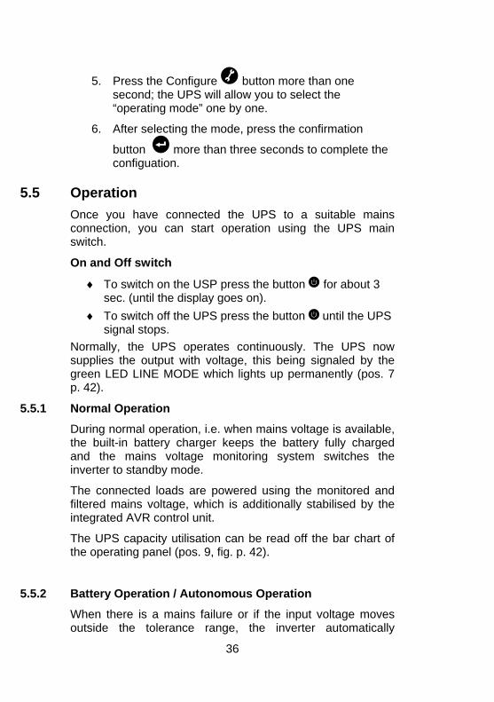
5. Press the Configure button more than one second; the UPS will allow you to select the “operating mode” one by one.
6. After selecting the mode, press the confirmation
button more than three seconds to complete the configuation.
5.5 Operation
5.5.2 Battery Operation / Autonomous Operation
When there is a mains failure or if the input voltage moves outside the tolerance range, the inverter automatically
Once you have connected the UPS to a suitable mains connection, you can start operation using the UPS main switch.
On and Off switch
♦ To switch on the USP press the button for about 3 sec. (until the display goes on).
♦ To switch off the UPS press the button until the UPS signal stops.
Normally, the UPS operates continuously. The UPS now supplies the output with voltage, this being signaled by the green LED LINE MODE which lights up permanently (pos. 7 p. 42).
5.5.1 Normal Operation
During normal operation, i.e. when mains voltage is available, the built-in battery charger keeps the battery fully charged and the mains voltage monitoring system switches the inverter to standby mode.
The connected loads are powered using the monitored and filtered mains voltage, which is additionally stabilised by the integrated AVR control unit.
The UPS capacity utilisation can be read off the bar chart of the operating panel (pos. 9, fig. p. 42).
36
switches over to autonomous mode and supplies the loads
e battery is fully discharged. This
double acoustic signal (once
with voltage from the battery. This drains the capacity of the battery and it is discharged. This status is signalled by the yellow LED BAT.MODE flashing as well as an intermittent acoustic signal (s. p. 42)
If the UPS does not automatically return to normal operation after a few minutes, close all jobs as usual and switch off your loads (e.g. PC) before thlengthens the service life of the battery! Switch OFF the UPS by pressing the main switch .
During the discharge process as the battery capacity consistently drops, the LED BAT.MODE flashes, accompanied by an intermitt nt eevery four seconds). When the battery undervoltage limit is reached (acoustic signal every second), the electronic of the UPS switches off the power supply for the loads.
Never store the unit in this condition! The discharged battery system should be recharged within a week.
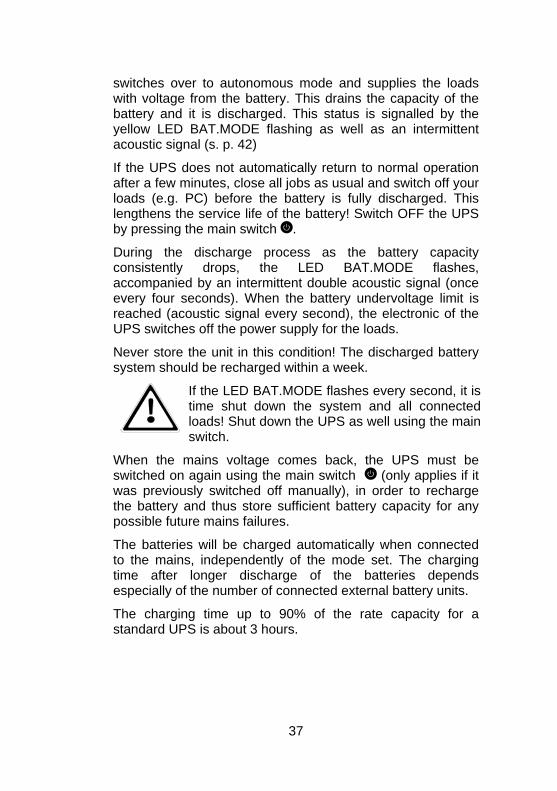
time shut down the system and all connectedloads! Shut down the UPS as w
If the LED BAT.MODE flashes every second, it is
ell using the main
When the mswitched owas previously switched off manually), in order to recharge
of the batteries depends
switch.
ains voltage comes back, the UPS must be again using the main switch (only applies if it n
the battery and thus store sufficient battery capacity for any possible future mains failures.
The batteries will be charged automatically when connected to the mains, independently of the mode set. The charging time after longer dischargeespecially of the number of connected external battery units.
The charging time up to 90% of the rate capacity for a standard UPS is about 3 hours.
37
5.5.3 Unit Overload
the unit is overloaded (load > 110 %), an intermittent signal er supply to the connected loads is
er the connected total load must be
liances to the UPS.
Ifis heard. The powmaintained, howevreduced immediately.
Non-observance of the "Unit overload" condition may cause the total loss of all UPS functions!
Also avoid short-term unit overloads, which may, for example, occur when connecting a laser printer or laser fax machine. Do not connect any household app
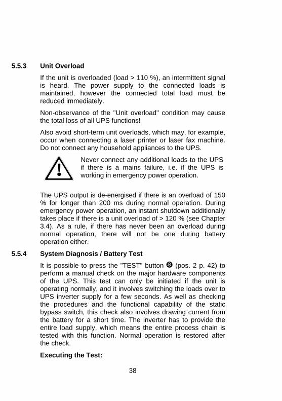
Never connect any additional loads to the UPS if there is a mains failure, i.e. if the UPS is working in emergency power operation.
The UPS out% for long During emergency power operation, an instant shutdown additionally
5.5.4
ress the "TEST" button
put is de-energised if there is an overload of 150 than 200 ms during normal operation.er
takes place if there is a unit overload of > 120 % (see Chapter 3.4). As a rule, if there has never been an overload during normal operation, there will not be one during battery operation either.
System Diagnosis / Battery Test
It is possible to p (pos. 2 p. 42) to jor hardware components
be initiated if the unit is perform a manual check on the maof the UPS. This test can only operating normally, and it involves switching the loads over to UPS inverter supply for a few seconds. As well as checking the procedures and the functional capability of the static bypass switch, this check also involves drawing current from the battery for a short time. The inverter has to provide the entire load supply, which means the entire process chain is tested with this function. Normal operation is restored after the check.
Executing the Test:
38
♦ To execute the manual check press the button for about five seconds until the UPS acoustic signal fades out.
♦ Additionally the button has the function to deactivate the acoustic alarm signal. Press the button when the acoustic alarm it audible for about 1 second. The tone stops. Any new error that is reported by a signal activates the alarm signal again.
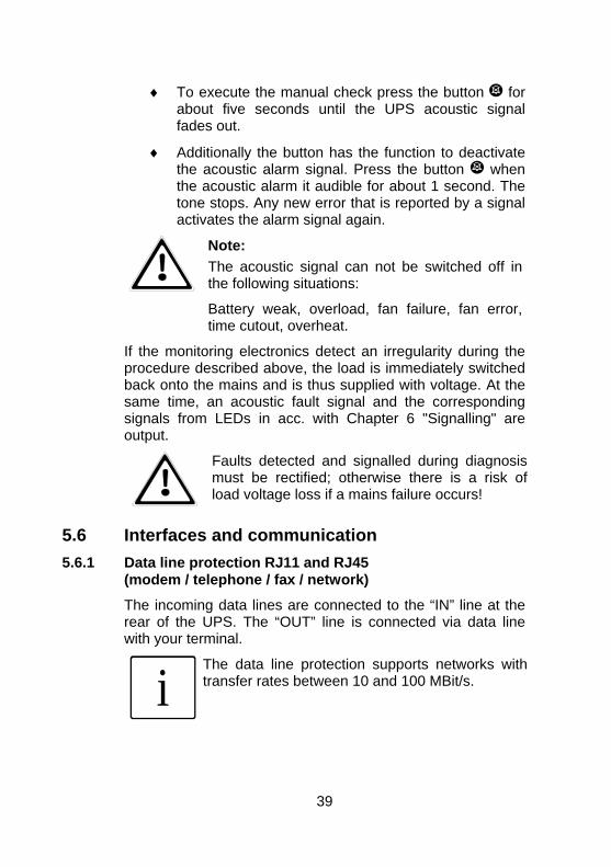
Note: The acoustic signal can not be switched off in the following situations:
Battery weak, overload, fan failure, fan error,
If the monitoring electronics detect an irregularity during the procedure dback onto thsame time, an acoustic fault signal and the corresponding
time cutout, overheat.
escribed above, the load is immediately switched e mains and is thus supplied with voltage. At the
signals from LEDs in acc. with Chapter 6 "Signalling" are output.
Faults detected and signalled during diagnosis must be rectified; otherwise there is a risk of load voltage loss if a mains failure occurs!
5.6 Interfaces 5.6.1 Data line p
(modem / telephone / fax / network)
to the “IN” line at the nnected via data line
and communication tection RJ11 and RJ45 ro
The incoming data lines are connected rear of the UPS. The “OUT” line is cowith your terminal.
iThe data line protection supports networks withtransfer rates between 10 and 100 MBit/s.
39
5.6.2 Computer i
The UPS offers various interfaces to manage the system and to comfortable readout state information and important parameters. The protocol is optimized for operation with the
ware “CompuWatch”
nterfaces RS232 and USB
shutdown and UPS management softfrom AEG. To connect to the UPS use the provided RS232 or USB cable by attaching them to a free port of your pc.
RS232 interface: The interface is connected via a 9 pole Sub-D connector on the back of the unit (pos. 4 p. 24 / 25). PIN: 2 = RxD; 3 = TxD; 5 = GND.
USB interface: The connection via USB is recognized automatically (pos 5 p. 24 / 25).
i
USB- and RS232 interfaces can not be used at thesame time.
5.6.3 Communic(PROTECT B. 1500 / 2000 / 3000):
If the cover on the rear of the UPS is removed, additional optionally available communication components can be
status messages,
5.6.4 are
In combination with the intelligent UPS the software ensures high availability of all IT components and full data integrity.
ation slot
installed there.
AS/400 board: Slot card withrealised via potential-free relay contacts
SNMP board: Slot card for direct connection of the UPS to the Ethernet network with RJ 45 (TCP/IP)
Details can be found in the description enclosed with the particular optional component. Other boards are in preparation.
Shutdown and UPS management softw
Especially for monitoring the state of the UPS and the supply of power AEG developed the software “CompuWatch”.
40
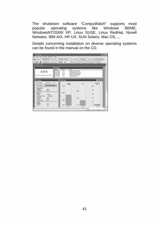
The shutdown software “CompuWatch” supports most
popular operating systems like Windows 98/ME,WindowsNT/2000/ XP, Linux SUSE, Linux RedHat, NovellNetware, IBM AIX, HP-UX, SUN Solaris, Mac OS, ...
Details concerning installation on diverse operating systems can be found in the manual on the CD.
41
6 Signalling and failure solution 6.1 LED display
tch of the UPS (mains switch) ton for manually triggering the system test or
switching off the buzzer 3. Push button to view the configuration
dicator will S accepts AC
20%.
er for
6.
7. wer mode. The line ource is
LED UPS
is providing battery power to your equipment. On the
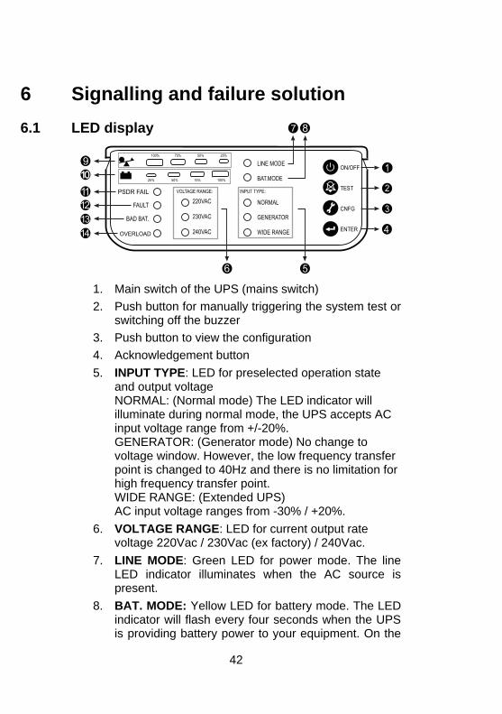
1. Main swi2. Push but
4. Acknowledgement button 5. INPUT TYPE: LED for preselected operation state
and output voltage NORMAL: (Normal mode) The LED inilluminate during normal mode, the UPinput voltage range from +/-GENERATOR: (Generator mode) No change to voltage window. However, the low frequency transfpoint is changed to 40Hz and there is no limitationhigh frequency transfer point. WIDE RANGE: (Extended UPS) AC input voltage ranges from -30% / +20%. VOLTAGE RANGE: LED for current output rate voltage 220Vac / 230Vac (ex factory) / 240Vac. LINE MODE: Green LED for poLED indicator illuminates when the AC spresent.
8. BAT. MODE: Yellow LED for battery mode. Theindicator will flash every four seconds when the
42
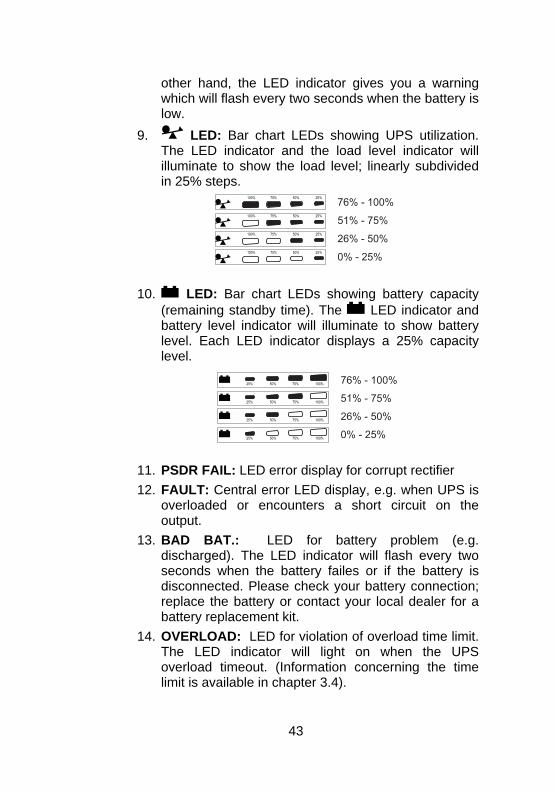
other hand, the LED indicator gives you a warning which will flash every two seconds when the battery is low.
LED: Bar chart LEDs showing UPS utilization. The LED indicator and the load level indicator will illuminate to show the load level; linearly subdivided in 25% steps.
9.
10. LED: Bar chart LEDs showing battery capacity
(remaining standby time). The LED indicator and battery level indicator will illuminate to show battery level. Each LED indicator displays a 25% capacity level.
11. PSDR FAIL: 12. FAULT: when UPS is
on the output.
13. BAD BAT.:two is
eplacement kit.
LED error display for corrupt rectifier Central error LED display, e.g.
overloaded or encounters a short circuit
LED for battery problem (e.g. discharged). The LED indicator will flash every seconds when the battery failes or if the batterydisconnected. Please check your battery connection; replace the battery or contact your local dealer for a battery r
14. OVERLOAD: LED for violation of overload time limit. The LED indicator will light on when the UPS overload timeout. (Information concerning the time limit is available in chapter 3.4).
43
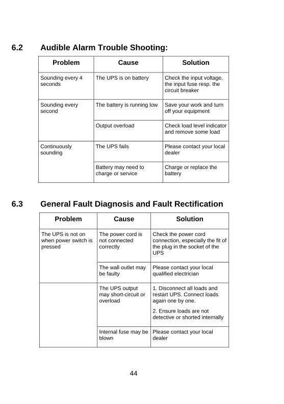
6.2 Audible Alarm Trouble Shooting:
Problem Cause Solution
Soundingseconds the input fuse resp. the
circuit breaker
every 4 The UPS is on battery Check the input voltage,
The battery is running low Save your work and turn off your equipment
Sounding every second
Output overload Check load level indicator
and remove some load
The UPS fails Please contact your local dealer
Continuously sounding
Battery may need to charge or service
Charge or replace the battery
6.3 General Fault Diagnosis and Fault Rectification
Problem Cause Solution
The power cord is not connected correctly
Check the power cord connection, especially the fit of the plug in the socket of the UPS
The UPS is not on when power switch is pressed
The wall outlet may be faulty
Please contact your local qualified electrician
The UPS output may short-circuit or overload
1. Disconnect all loads and restart UPS. Connect loads again one by one.
2. Ensure loads are not detective or shorted internally
Internal fuse may be blown
Please contact your local dealer
44
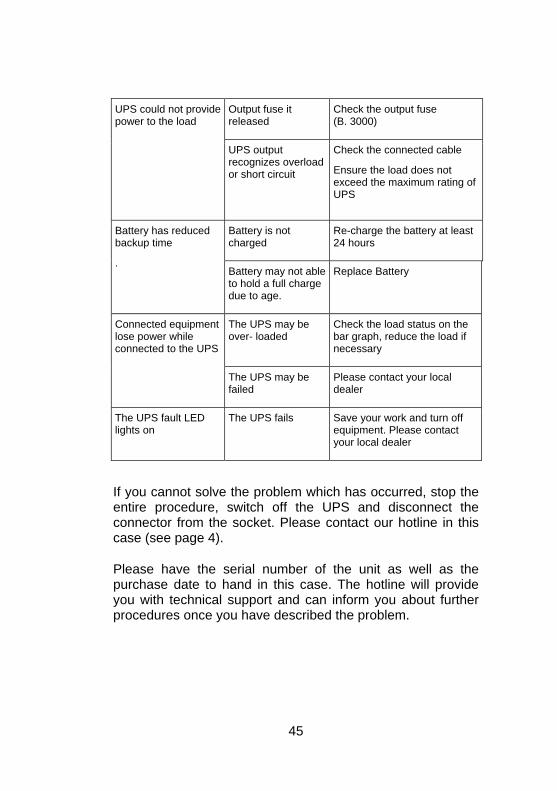
Output fuse it release
Check the output fuse (B. 3000) d
UPS could not provide pow
or short circuit
he
Ensuexceed the maximum rating of UPS
er to the load
UPS output recognizes overload
C ck the connected cable
re the load does not
Battery is not Re-charge the battery at least 24 hcharged ours
Batterybackup time
has reduced
. Battery may not able
harge Replace Battery
to hold a full cdue to age.
The UPS may be over- loaded
Check the load status on the bar graph, reduce the load if necessary
Connected equipment lose power while connected to the UPS
The UPS may be Please contact your local failed dealer
The UPS fault LED lights
The UPS fails Save your wequipment. Please contact your local dealer
on ork and turn off
If you cannot solve the problem which has occurred, stop the entire procedure, switch off the UPS and disconnect the connector from the contact our hotline in this case (see page 4).
lease have the s e purchase date to h . e you with technical support and can inform you about further procedures once you have described
socket. Please
P erial number ofand in this case
the unit as well as th The hotline will provid
the problem.
45
7 PROTECT B. consists of advanced and resistant
mponents. To gu nuous and high availability it recommended to check the unit (especially the batteries and e fans) in regular i ast e
Maintenance The co arantee a conti
ntervals (at leisth very 6 months).
CAUTION: Follow safety and security regulations
n
Visual control
When going through the visual control check whether:
ig
♦ conducting dirt or dust sediments are in the unit and
♦ dust sediments prevent optimal ventilation in and out the unit.
unco ditionally!
♦ mechanicasystem
l defects or fore n matter is visible in the
CAUTION: Before going through the next step disconnect the PROTECT B. from the mains.
r the visual control depend mainly on the local situation at the deployment site.
long the standby time lasts. The load should always be the same for each simulation. Dramatic changes compared to the last measurements require a change of batteries. Contact your local dealer or call our hotline (see page 4).
If the unit is very dusty it is recommended to clean the UPS with compressed air to enable optimal ventilation.
The time intervals fo
Battery control The aging process can be detected by regular capacity probes. Make comparison measurements every 12 month e.g. by simulating a power failure and check how
46
Fan control on a regular basis for dust al sounds. Clogged ventilation
7.1
The fan has to be checkedintrusion and strange untypichas to be cleaned. If the fan makes a strange noise or runs irregular contact the hotline (see page 4).
Battery replacement
C
A battery can present a risk of electrical and can be very dangerous if handledimproperly. The following precautions should be
erved before replacing the batteries.
power
♦ recycle or dispose of used battery. Do not dispose in a fire. The batteries may explode
AUTION:
shock
obs
♦ Turn off the UPS and disconnect the utility cord from the wall outlet.
♦ Remove rings, watches, and other metal objects.
♦ If the battery replacement kit is damaged in anywayor shows signs of leakage, contact your dealer immediately.
Properly of batteries.
i
If you are not qualified service personnel toreplace the battery, do not attempt to open the
Note:
battery door. Please call local dealer ordistributor immediately.
47
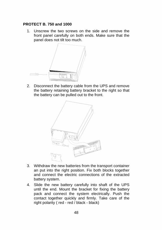
PROTECT B. 750 and 1000
1. Unscrew the two screws on the side and remove the front panel carefully on both ends. Make sure that the panel does not tilt too much.
2
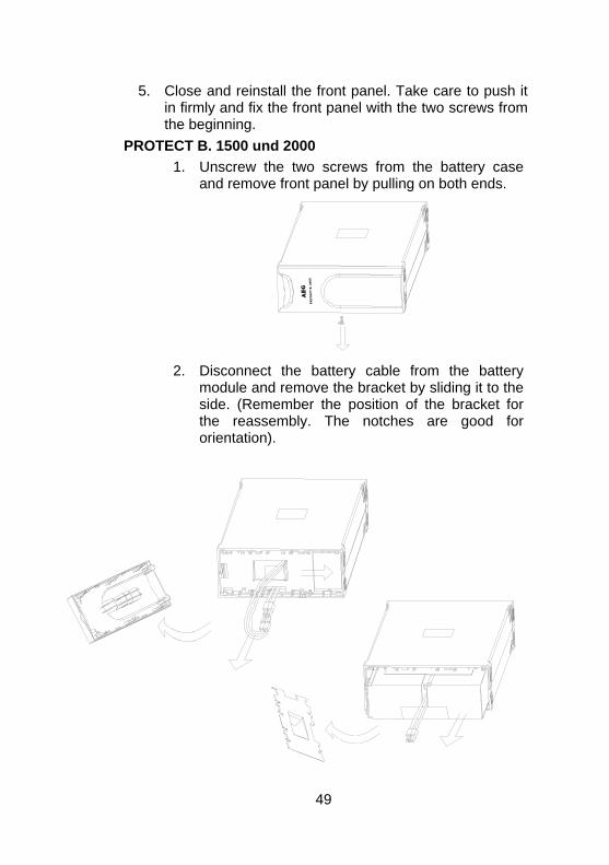
th bracket to the right so that the battery can be pulled out to the front.
. Disconnect the battery cable from the UPS and remove e battery retaining battery
3. Withdraw the new batteries from the transport container
an put into the right position. Fix both blocks together and connect the electric connections of the extracted battery system.
4. Slide the new battery carefully into shaft of the UPS until the end. Mount the bracket for fixing the battery pack and connect the system electrically. Push the contact together quickly and firmly. Take care of the right polarity ( red - red / black - black)
48
5. Close and reinstall the front panel. Take care to push it
PROT1. Unscrew the two screws from the battery case
and remove front panel by pulling on both ends.
in firmly and fix the front panel with the two screws from the beginning. ECT B. 1500 und 2000
2. Disconnect the battery cable from the battery
module and remove the bracket by sliding it to the side. (Remember the position of the bracket for the reassembly. The notches are good for orientation).
49
3. Withdraw the new batteries from the transport container and put into the right position. Fix both blocks together and connect the electric
xtracted battery system.
5. Mount the bracket for fixing the battery pack and connect the cable joint between the battery packs (red-red / black-black). Close and reinstall the front panel. Take care to push it in firmly and fix the front panel with the two screws from the beginning.
The battery exchange is completed.
connections of the e
4. Slide the new battery carefully into shaft of the UPS until the end.
i
Alternatively a complete battery module can be
PROTECT
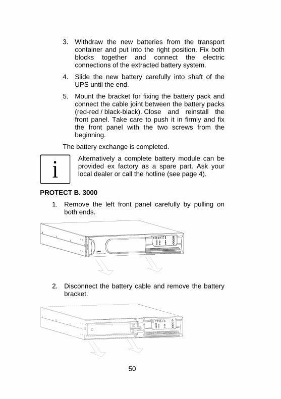
1. Re
provided ex factory as a spare part. Ask your local dealer or call the hotline (see page 4).
B. 3000
move the left front panel carefully by pulling onboth ends.
2. Disconnect the battery cable and remove the battery
bracket.
50
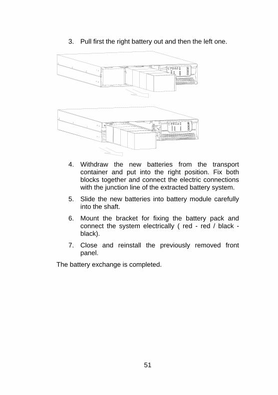
3. Pull first the right battery out and then the left one.
draw the new batteries from the transport ainer and put into the right position. Fix
4. Withcont both blocks together and connect the electric connections
tion line of the extracted battery system.
6. Mount the bracket for fixing the battery pack and connect the system electrically ( red - red / black - black).
7. Close and reinstall the previously removed front panel.
The battery exchange is completed.
with the junc
5. Slide the new batteries into battery module carefully into the shaft.
51
8 Storage, Dismantling and Disposal Storage
rLong storage times without charging o
discharging the battery at regular intervals maylead to permanent damage of the battery.
If the battery is stored at room temperature (200C to 300C) it will automatically discharge at a rate of 3-6 % per month due to internal reactions. Storing the battery at temperatures above room temperature should be avoided. A high storage temperature also means greater battery self-discharge.
Batrechservice
teries that are stored at room temperature should be arged every six months to maintain their full capacity and
life.
i
before putting it into storage, in order to makesure that the battery is fully charged.
Connect PROTECT B. to the mains without load
The charging time should be at least as long asrecommended in chapter 3.4 “Technical Data”.
ntling DismaTheinstructi
isposal the interest of environmental protection and recycling, lease dispose condemned components in accordance with e regulations and legal guidelines when permanently taking
the system out of operation.
system is dismantled in reverse order of the installation ons.
DInpth
52
9 Glossary 9.1 Technical terms
AAVR utomatic Voltage Regulation against mains
DC/DC Booster
voltage variations
Circuit technology to boost the direct current on a higher voltage level
EPO Emergency Power Off device for emergency shut down
PFC Power Factor Correction Circuit technology to minimize circuit backfeed (important for non linear loads)
Appliance protection Surge technology term The conventional mains surge protection consists of an mains earthwire (class B), an overvoltage protection (class C) and an appliance protection (class D) – see also e.g. under http://www.phoenixcontact.de (topic „TRABTECH“)
Class D
LED
see appliance protection
Light Emitting Diode Electronic semiconductor component, commonly called light diode. Used for optical signaling.
SNMP Simple Network Management Protocol common protocol in networks to manage / control appliances
VFD Output Voltage and Frequency Dependent from mains supply The UPS output depends of mains voltage and frequency variations. Former notation: OFFLINE
Output VVI oltage Independent from mains supply
ut V
The UPS output is independent of mains voltage and frequency variations. The mains voltage however is rectified by electronic / passive voltage regulators. Former notation: LINE-INTERACTIVE
VFI Outp oltage and Frequency Independent from
The UPS output is independent of mains voltage and frequency variations. Former notation: OFFLINE
mains supply
53
Guarantee Certificate
Type: …….……………….…......................................................
Serial No.: ………….…............……………...............................
Date of Purcase: ………………............……………………........ Trading Stamp / Signature Subject to change without notice
AEG Power Supply Systems GmbH Emil-Siepmann-Straße 32
59581 Warstein-Belecke
Germany
Operating Instructions
BAL 8000015757 EN
AEG0106EN

![Grundfos UPS 40-120 F B pump : UPS40-120 F B 3x400-415V ......Printed from Grundfos Product Centre [2018.02.043] Position Qty. Description 1 UPS 40-120 F B Note! Product picture may](https://img.pdfslide.us/doc/110x75/61080c1adc420524bb7a7746/grundfos-ups-40-120-f-b-pump-ups40-120-f-b-3x400-415v-printed-from-grundfos.jpg)