Embed Size (px)
DESCRIPTION
https://www.uponor.co.uk/~/media/countryspecific/uk/download-centre/brochure/uponor-preinsulated-distribution-for-industrial-lr.pdf?version=1
Citation preview
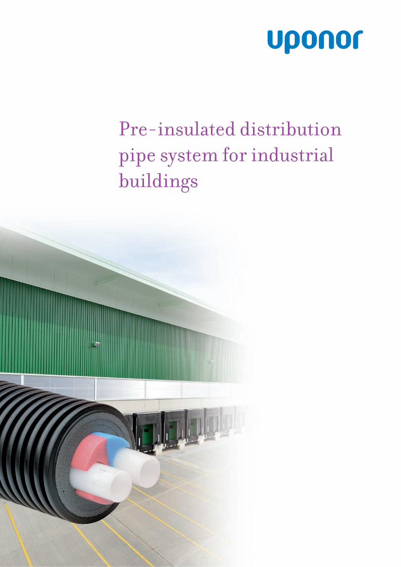
Pre-insulated distribution pipe system for industrial buildings
2 3
"The flexibility of Uponor pre insulated pipes allows them to be adapted to almost any type of routing conditions on site." All technical and legal information contained in this catalogue has
been carefully compiled according to the best of our knowledge. We cannot be held liable for any errors as these cannot be fully excluded. Technical guidelines, including all sections, are protected by copyright. All uses other than those permitted under the copyright law are not allowed without the approval of Uponor. This applies particularly to reproduction, re-prints, processing, storage and processing in electronic systems, translations and microfi lming. The contents of the technical guidelines are subject to change without notice.
Copyright 2010 Uponor
Table of contentsFlexible solution ................................................. 4
Pipe installation ................................................ 5
Designing indoor pipe routing ......................... 6 Bending radii .................................................... 8 Mounting on the wall or on the ceiling ............ 8 Thermal elongation .......................................... 9 Installation in cold temperatures ...................... 9
Dimensioning heat pipes ................................... 10 Pressure loss table ............................................ 11
Product details - Uponor Thermo Twin ........... 12
Range of accessories for pre-insulated pipe systems ...................................................... 13
Wipex connector overview ................................ 13 Connectors ....................................................... 14 Accessories ....................................................... 16
Mounting Instructions ...................................... 18 Uponor Wipex fittings ....................................... 18 T-branches ....................................................... 19
Extension ............................................................ 22
Testing system .................................................... 23 Pressure test for the pipeline ............................ 23 Pressure and leak testing according
to DIN 18380 ........................................................ 24
Technical specifications..................................... 26
Material properties ............................................ 28
Notes on processing and installation .............. 29
Case study ........................................................... 30
min 0.5 mmax 6.0 m
4 5
Flexible solution
Uponor Pre-insulated distribution pipe system for industrial buildings Uponor Pre-insulated distribution pipe system for industrial buildings
No welding, no special tools. The flexibility and low weight of our pre-insulated pipes mean that they are easy to handle and building work can proceed fast. They are also supported by a comprehensive range of accessories. From a variety of wall lead-throughs, insulation kits and a proven range of fittings.
"The high quality of the flexible, pre-insulated pipes from Uponor is due to the strengths of the individual elements."
The high quality of the flexible, pre-insulated pipes from Uponor is due to the strengths of the individual elements. The combination of stable yet fl exible jacket pipes, ageing-resistant, crosslinked polyethylene insulating layers and robust, long-life media pipes creates system pipes that can be laid easily and quickly and function reliably.
Site preparation
The flexibility of Uponor Pre-insulated pipes allows them to be adapted to almost any type of routing conditions on site. They can be installed either into the ground or mounted onto ceilings or walls with cable shelves or brackets. They can cross over or under existing pipes, or be routed around obstacles. The system requires only a shallow narrow trench to be excavated. The trenches around the pipe connections and branches should normally not be walked over during installation, so sufficient working space should be created at these points. Where the direction of a pipeline changes the various pipe systems must not fall below the permissible minimum bending radii. Excavated soil can be deposited on just one side of the trench. The pipeline is then rolled out on the other side direct into the trench. It is essential to avoid damage to the jacket pipe.
The trench must have a sandy bed, free of stones. Sand particle size should be 0 to 2/3 mm. Avoid any pointed or sharp-edged objects in the trench. The pipeline must be carefully embedded (at least 10 cm below and above the jacket
pipe and between the trench walls) as this has a decisive impact on the service life of the jacket pipe. When determining the minimum coverage, any possible damage through subsequent construction work during the whole of the service life of the pipeline must be taken into consideration. The filling material must be compacted layer for layer and from 500 mm the coverage must also be compacted by machine. The routing barrier tape should then be put in place, and the trench filled in.
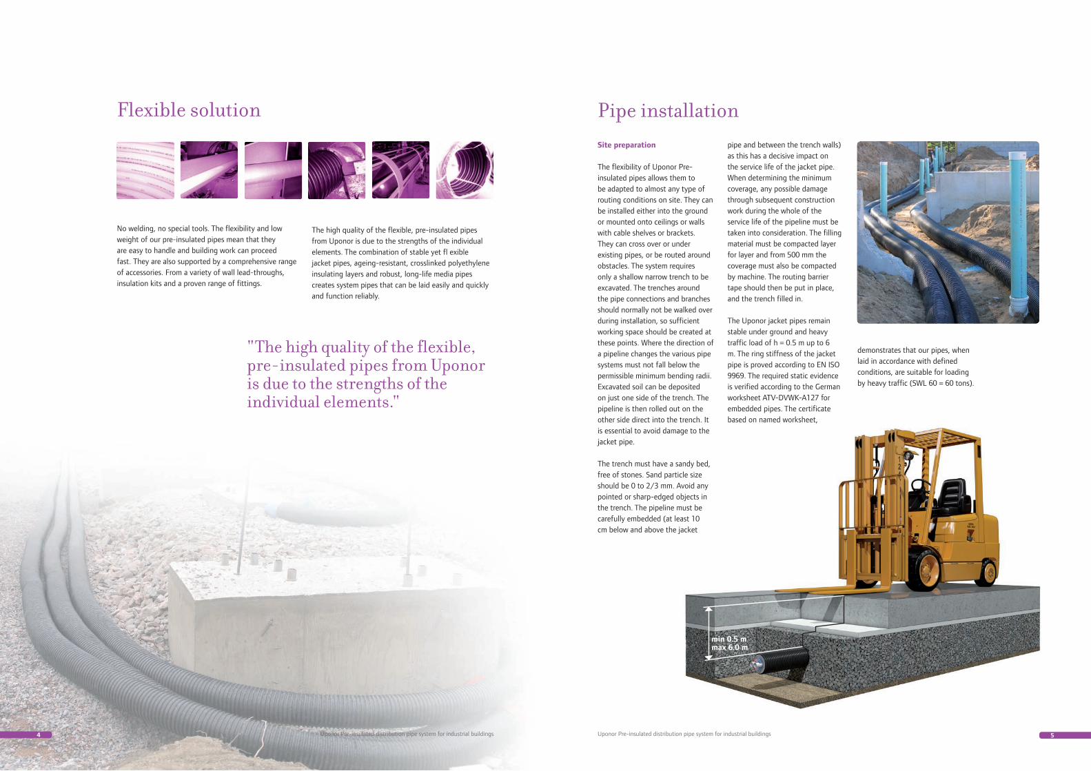
The Uponor jacket pipes remain stable under ground and heavy traffic load of h = 0.5 m up to 6 m. The ring stiffness of the jacket pipe is proved according to EN ISO 9969. The required static evidence is verified according to the German worksheet ATV-DVWK-A127 for embedded pipes. The certificate based on named worksheet,
Pipe installation
demonstrates that our pipes, when laid in accordance with defined conditions, are suitable for loading by heavy traffic (SWL 60 = 60 tons).
6 7Uponor Pre-insulated distribution pipe system for industrial buildings Uponor Pre-insulated distribution pipe system for industrial buildings
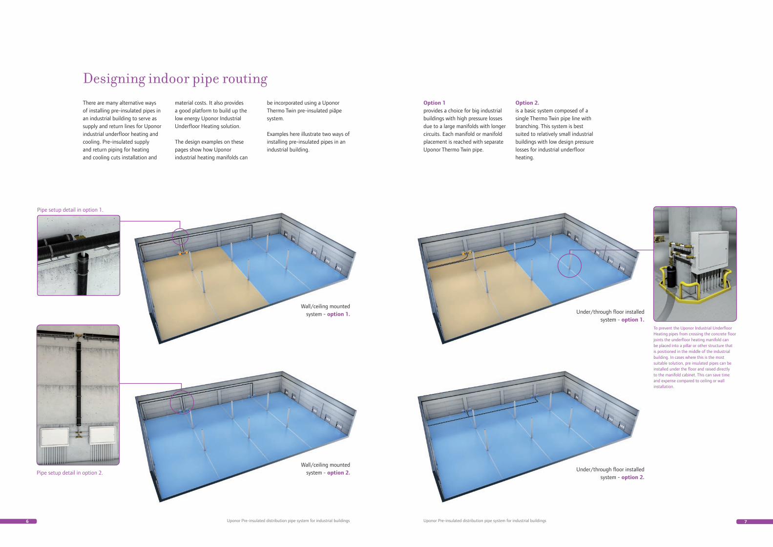
There are many alternative ways of installing pre-insulated pipes in an industrial building to serve as supply and return lines for Uponor industrial underfloor heating and cooling. Pre-insulated supply and return piping for heating and cooling cuts installation and
Designing indoor pipe routingmaterial costs. It also provides a good platform to build up the low energy Uponor Industrial Underfloor Heating solution.
The design examples on these pages show how Uponor industrial heating manifolds can
Option 1provides a choice for big industrial buildings with high pressure losses due to a large manifolds with longer circuits. Each manifold or manifold placement is reached with separate Uponor Thermo Twin pipe.
Option 2. is a basic system composed of a single Thermo Twin pipe line with branching. This system is best suited to relatively small industrial buildings with low design pressure losses for industrial underfloor heating.
Wall/ceiling mounted system - option 1.
Wall/ceiling mounted system - option 2.
Under/through floor installed system - option 1.
Under/through floor installed system - option 2.
Pipe setup detail in option 1.
Pipe setup detail in option 2.
To prevent the Uponor Industrial Underfloor Heating pipes from crossing the concrete floor joints the underfloor heating manifold can be placed into a pillar or other structure that is positioned in the middle of the industrial building. In cases where this is the most suitable solution, pre insulated pipes can be installed under the floor and raised directly to the manifold cabinet. This can save time and expense compared to ceiling or wall installation.
be incorporated using a Uponor Thermo Twin pre-insulated piåpe system.
Examples here illustrate two ways of installing pre-insulated pipes in an industrial building.
8 9
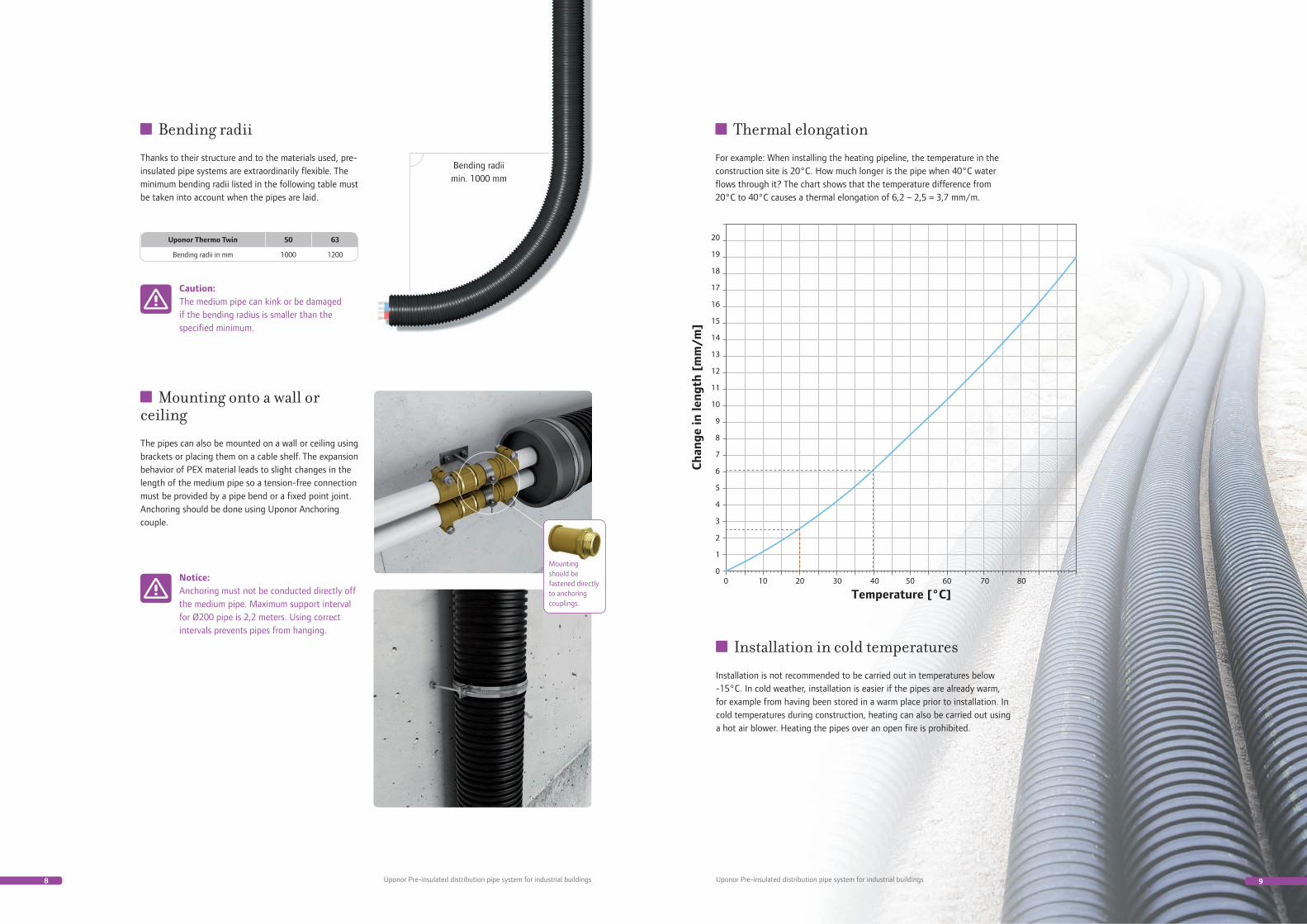
Bending radii min. 1000 mm
Mounting should be fastened directly to anchoring couplings.
Uponor Pre-insulated distribution pipe system for industrial buildings Uponor Pre-insulated distribution pipe system for industrial buildings
Thermal elongation
For example: When installing the heating pipeline, the temperature in the construction site is 20°C. How much longer is the pipe when 40°C water flows through it? The chart shows that the temperature difference from 20°C to 40°C causes a thermal elongation of 6,2 – 2,5 = 3,7 mm/m.
Installation in cold temperatures
Installation is not recommended to be carried out in temperatures below -15°C. In cold weather, installation is easier if the pipes are already warm, for example from having been stored in a warm place prior to installation. In cold temperatures during construction, heating can also be carried out using a hot air blower. Heating the pipes over an open fire is prohibited.
Uponor Thermo Twin 50 63
Bending radii in mm 1000 1200
Bending radii
Thanks to their structure and to the materials used, pre-insulated pipe systems are extraordinarily flexible. The minimum bending radii listed in the following table must be taken into account when the pipes are laid.
Mounting onto a wall or ceiling
The pipes can also be mounted on a wall or ceiling using brackets or placing them on a cable shelf. The expansion behavior of PEX material leads to slight changes in the length of the medium pipe so a tension-free connection must be provided by a pipe bend or a fixed point joint. Anchoring should be done using Uponor Anchoring couple.
Caution:The medium pipe can kink or be damaged if the bending radius is smaller than the specified minimum.
Notice:Anchoring must not be conducted directly off the medium pipe. Maximum support interval for Ø200 pipe is 2,2 meters. Using correct intervals prevents pipes from hanging.
10 11Uponor Pre-insulated distribution pipe system for industrial buildings Uponor Pre-insulated distribution pipe system for industrial buildings
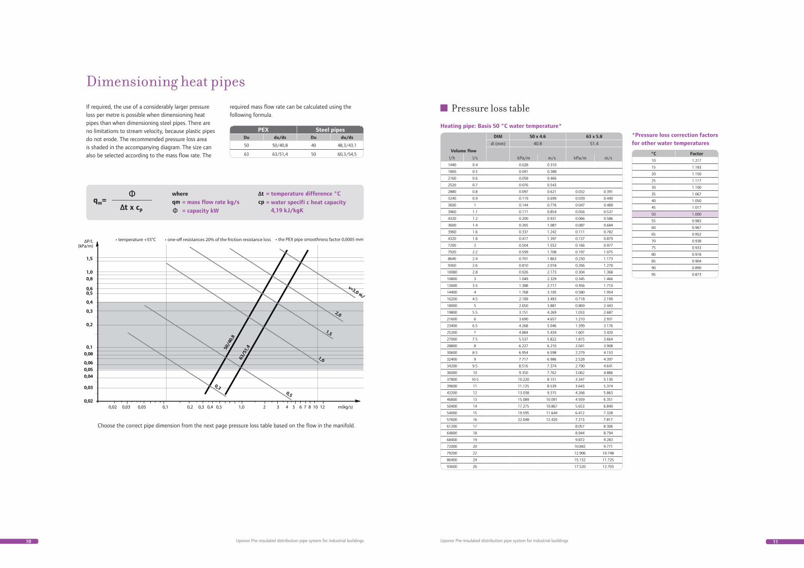
If required, the use of a considerably larger pressure loss per metre is possible when dimensioning heat pipes than when dimensioning steel pipes. There are no limitations to stream velocity, because plastic pipes do not erode. The recommended pressure loss area is shaded in the accompanying diagram. The size can also be selected according to the mass flow rate. The
Dimensioning heat pipesrequired mass flow rate can be calculated using the following formula.
= mass flow rate kg/s= temperature difference °C
= water specifi c heat capacity 4,19 kJ/kgK= capacity kW
PEX Steel pipesDu du/ds Du du/ds
50 50/40,8 40 48,3/43,1
63 63/51,4 50 60,3/54,5
Choose the correct pipe dimension from the next page pressure loss table based on the flow in the manifold.
DIM 50 x 4.6 63 x 5.8
di (mm) 40.8 51.4
Volume flow
l/h l/s kPa/m m/s kPa/m m/s
1440 0.4 0.028 0.310
1800 0.5 0.041 0.388
2160 0.6 0.058 0.466
2520 0.7 0.076 0.543
2880 0.8 0.097 0.621 0.032 0.391
3240 0.9 0.119 0.699 0.039 0.440
3600 1 0.144 0.776 0.047 0.489
3960 1.1 0.171 0.854 0.056 0.537
4320 1.2 0.200 0.931 0.066 0.586
3600 1.4 0.265 1.087 0.087 0.684
3960 1.6 0.337 1.242 0.111 0.782
4320 1.8 0.417 1.397 0.137 0.879
7200 2 0.504 1.552 0.166 0.977
7920 2.2 0.599 1.708 0.197 1.075
8640 2.4 0.701 1.863 0.230 1.173
9360 2.6 0.810 2.018 0.266 1.270
10080 2.8 0.926 2.173 0.304 1.368
10800 3 1.049 2.329 0.345 1.466
12600 3.5 1.388 2.717 0.456 1.710
14400 4 1.768 3.105 0.580 1.954
16200 4.5 2.189 3.493 0.718 2.199
18000 5 2.650 3.881 0.869 2.443
19800 5.5 3.151 4.269 1.033 2.687
21600 6 3.690 4.657 1.210 2.931
23400 6.5 4.268 5.046 1.399 3.176
25200 7 4.884 5.434 1.601 3.420
27000 7.5 5.537 5.822 1.815 3.664
28800 8 6.227 6.210 2.041 3.908
30600 8.5 6.954 6.598 2.279 4.153
32400 9 7.717 6.986 2.528 4.397
34200 9.5 8.516 7.374 2.790 4.641
36000 10 9.350 7.762 3.062 4.886
37800 10.5 10.220 8.151 3.347 5.130
39600 11 11.125 8.539 3.643 5.374
43200 12 13.038 9.315 4.268 5.863
46800 13 15.089 10.091 4.939 6.351
50400 14 17.275 10.867 5.653 6.840
54000 15 19.595 11.644 6.412 7.328
57600 16 22.048 12.420 7.213 7.817
61200 17 8.057 8.306
64800 18 8.944 8.794
68400 19 9.872 9.283
72000 20 10.842 9.771
79200 22 12.906 10.748
86400 24 15.132 11.725
93600 26 17.520 12.703
°C Factor
10 1.217
15 1.183
20 1.150
25 1.117
30 1.100
35 1.067
40 1.050
45 1.017
50 1.000
55 0.983
60 0.967
65 0.952
70 0.938
75 0.933
80 0.918
85 0.904
90 0.890
95 0.873
Pressure loss table
Heating pipe: Basis 50 °C water temperature*
*Pressure loss correction factors for other water temperatures
12 13
10183691022281
10183571018332
Uponor Pre-insulated distribution pipe system for industrial buildings Uponor Pre-insulated distribution pipe system for industrial buildings
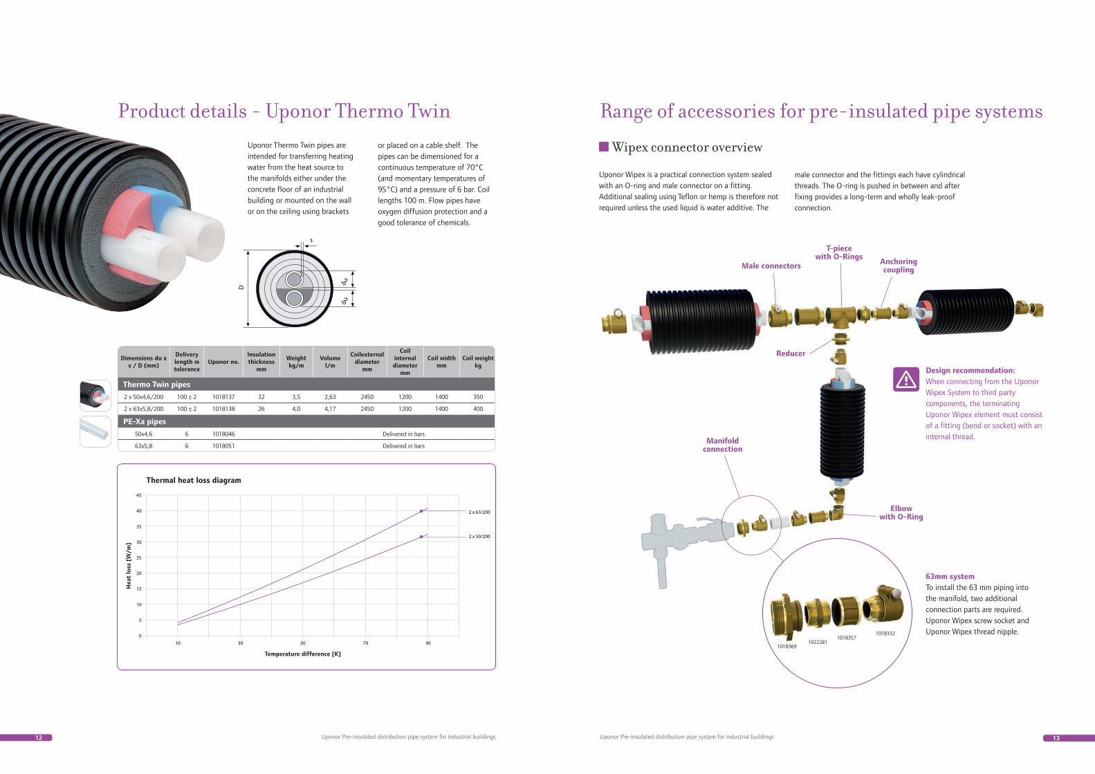
Uponor Thermo Twin pipes are intended for transferring heating water from the heat source to the manifolds either under the concrete floor of an industrial building or mounted on the wall or on the ceiling using brackets
Product details - Uponor Thermo Twinor placed on a cable shelf. The pipes can be dimensioned for a continuous temperature of 70°C (and momentary temperatures of 95°C) and a pressure of 6 bar. Coil lengths 100 m. Flow pipes have oxygen diffusion protection and a good tolerance of chemicals.
Dimensions du x s / D (mm)
Delivery length m tolerance
Uponor no.Insulation thickness
mm
Weight kg/m
Volume l/m
Coilexternal diameter
mm
Coil internal diameter
mm
Coil width mm
Coil weight kg
Thermo Twin pipes
2 x 50x4,6/200 100 ± 2 1018137 32 3,5 2,63 2450 1200 1400 350
2 x 63x5,8/200 100 ± 2 1018138 26 4,0 4,17 2450 1200 1400 400
PE-Xa pipes
50x4,6 6 1018046 Delivered in bars
63x5,8 6 1018051 Delivered in bars
Thermal heat loss diagram
Range of accessories for pre-insulated pipe systems
Uponor Wipex is a practical connection system sealed with an O-ring and male connector on a fitting. Additional sealing using Teflon or hemp is therefore not required unless the used liquid is water additive. The
Wipex connector overview
male connector and the fittings each have cylindrical threads. The O-ring is pushed in between and after fixing provides a long-term and wholly leak-proof connection.
63mm system To install the 63 mm piping into the manifold, two additional connection parts are required. Uponor Wipex screw socket and Uponor Wipex thread nipple.
Design recommendation:When connecting from the Uponor Wipex System to third party components, the terminating Uponor Wipex element must consist of a fitting (bend or socket) with an internal thread.
Male connectors
Elbowwith O-Ring
Anchoring coupling
Manifold connection
T-piecewith O-Rings
Reducer
Temperature difference [K]
Hea
t lo
ss [
W/m
]
14 15Uponor Pre-insulated distribution pipe system for industrial buildings Uponor Pre-insulated distribution pipe system for industrial buildings
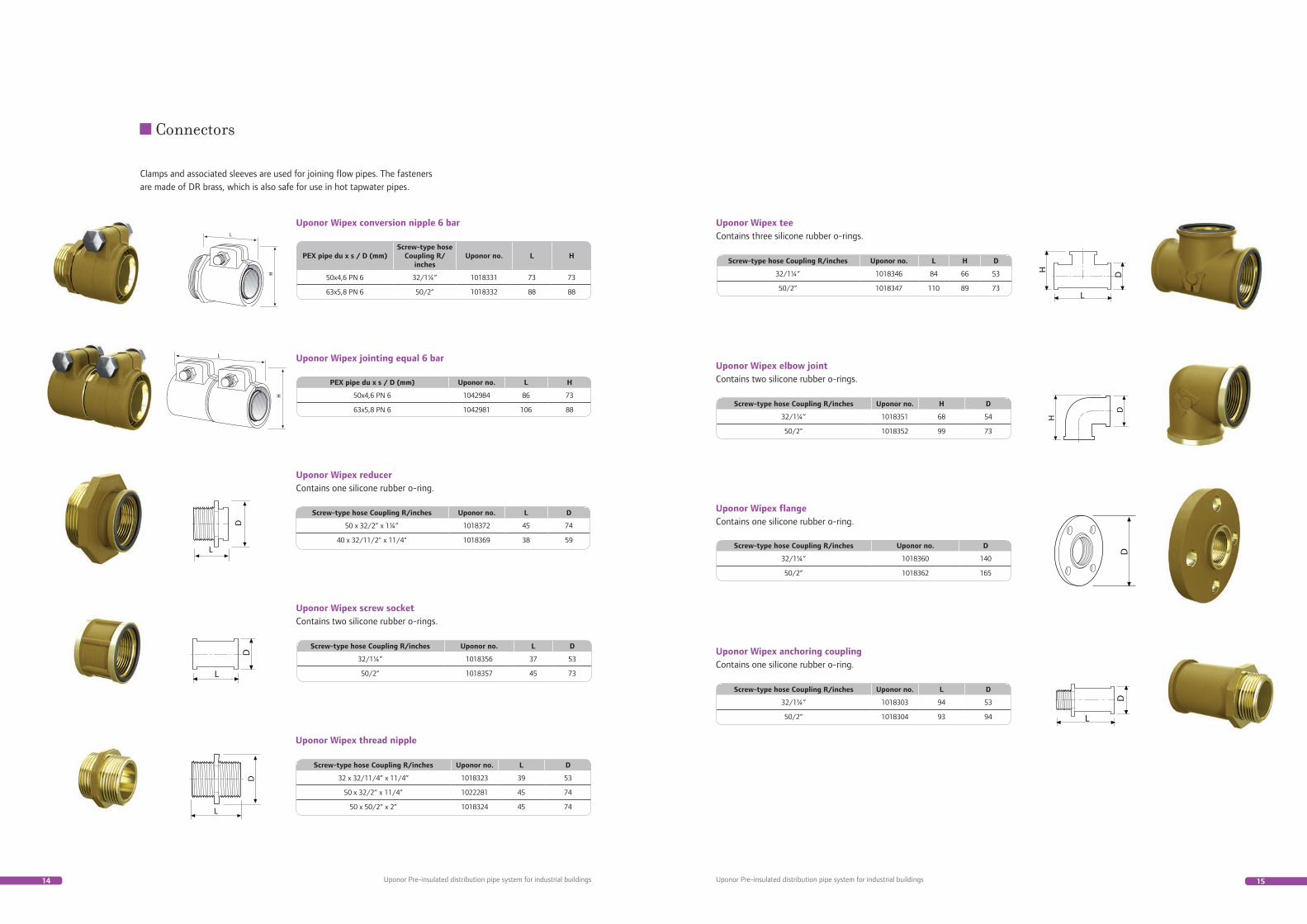
Clamps and associated sleeves are used for joining flow pipes. The fasteners are made of DR brass, which is also safe for use in hot tapwater pipes.
Connectors
Uponor Wipex reducerContains one silicone rubber o-ring.
PEX pipe du x s / D (mm)Screw-type hose
Coupling R/inches
Uponor no. L H
50x4,6 PN 6 32/1¼” 1018331 73 73
63x5,8 PN 6 50/2” 1018332 88 88
Screw-type hose Coupling R/inches Uponor no. L D
50 x 32/2” x 1¼” 1018372 45 74
40 x 32/11/2" x 11/4" 1018369 38 59
Uponor Wipex screw socketContains two silicone rubber o-rings.
Screw-type hose Coupling R/inches Uponor no. L D
32/1¼” 1018356 37 53
50/2” 1018357 45 73
Uponor Wipex conversion nipple 6 bar
PEX pipe du x s / D (mm) Uponor no. L H
50x4,6 PN 6 1042984 86 73
63x5,8 PN 6 1042981 106 88
Uponor Wipex jointing equal 6 bar
Uponor Wipex thread nipple
Screw-type hose Coupling R/inches Uponor no. L D
32 x 32/11/4” x 11/4” 1018323 39 53
50 x 32/2” x 11/4” 1022281 45 74
50 x 50/2” x 2” 1018324 45 74
Uponor Wipex tee Contains three silicone rubber o-rings.
Uponor Wipex elbow joint Contains two silicone rubber o-rings.
Uponor Wipex flange Contains one silicone rubber o-ring.
Uponor Wipex anchoring couplingContains one silicone rubber o-ring.
Screw-type hose Coupling R/inches Uponor no. L H D
32/1¼” 1018346 84 66 53
50/2” 1018347 110 89 73
Screw-type hose Coupling R/inches Uponor no. L D
32/1¼” 1018303 94 53
50/2” 1018304 93 94
Screw-type hose Coupling R/inches Uponor no. D
32/1¼” 1018360 140
50/2” 1018362 165
Screw-type hose Coupling R/inches Uponor no. H D
32/1¼” 1018351 68 54
50/2” 1018352 99 73

16 17
Reduction 200/175Reduction 175/140
Adhesive surfaces
54
321
6
OIL
Uponor Pre-insulated distribution pipe system for industrial buildings Uponor Pre-insulated distribution pipe system for industrial buildings
TypeCasing external ø frame/
branch (mm)Uponor no.
Weight kg/m
Frame length mm (L)
Type 1 200 1018277 2,6 770
Type 2 200/175/140 1021992 6,2 1200
Casing external ø frame/branch (mm)
Uponor no. Weight kg/m Du mm Di mm
200 1034204 0,6 255 200
T-branch insulation set For branching, insulating and sealing at the same level a level single or twin pipe element. The chute For branching, extending and feeding through insulated pipes. branches are the same size; smaller pipe sizes are sealed using reduction sleeves. The kit contains
TypeCasing external ø
frame/branch (mm)Uponor no.
Weight kg/m
Frame length mm (L)
Branch length mm (L
1)
Type 1 200/175-140 1018261 4,1 780 560
Type 2 200/175-140 1021990 8,2 1200 735
insulation chutes, clamp rings made of acid proof steel, sealant and reduction sleeves.
Joint insulation set For branching, insulating and sealing at the same level a level single or twin pipe element. The chute For branching, extending and feeding through insulated
pipes. branches are the same size; smaller pipe sizes are sealed using reduction sleeves. The kit contains insulation chutes, clamp rings made of acid proof steel, sealant and reduction sleeves.
Feed-through seal Efficiently seals the feed-through in a concrete structure and prevents moisture from entering the building.
Radon sealing has also been tested. The kit contains the feedthrough sea land associated clamp.
Accessories
Dimensions du/D (mm) Uponor no.
40-63, 40-63/200 1018307
Bend angle For supporting pipes exactly into place in base fl oor feed-throughs. Several bend angles can be joined together side by side.
Casing external ø mm Uponor no. R mm
200 1034303 1000
End caps End caps are made of EPDM rubber. The fl ow pipe and cable feed-throughs are cut open with scissors at the location specifi ed by the pipe size/cable. A fl exible feed-through is tight as it is. The rubber cap is
tightened around the casing with the help of a sealant and an acid proof clamp. The end cap prevents moisture from permeating the insulation layers on the pipe. It is always used in wells.
Installing the rubber end caps End caps are always used when there is a risk of moisture entering the pipe element.
Peel off the casing pipe and insulation so that enough flow pipe is visible to join the connector and the end cap. Be careful not to damage the flow pipe. Clean the surfaces carefully.
Install a washer on the second groove.
Open outputs on the rubber end cap according to the flow pipe size.
Install the end cap on top of the pipe using lubricant. Place a clamp on the end cap and washer and tighten until the ends of the spread are touching.
18 19
20mm8
7
6
5
4
3
2
1
87
654
321
Uponor Pre-insulated distribution pipe system for industrial buildings Uponor Pre-insulated distribution pipe system for industrial buildings
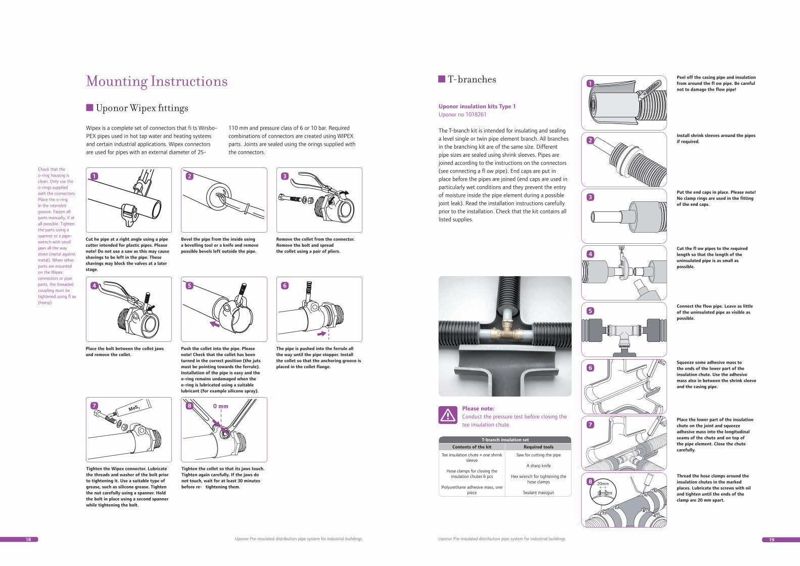
Wipex is a complete set of connectors that fi ts Wirsbo-PEX pipes used in hot tap water and heating systems and certain industrial applications. Wipex connectors are used for pipes with an external diameter of 25-
Mounting Instructions
Uponor Wipex fittings
110 mm and pressure class of 6 or 10 bar. Required combinations of connectors are created using WIPEX parts. Joints are sealed using the orings supplied with the connectors.
Check that the o-ring housing is clean. Only use the o-rings supplied with the connectors. Place the o-ring in the intended groove. Fasten all parts manually, if at all possible. Tighten the parts using a spanner or a pipe-wrench with small jaws all the way down (metal against metal). When other parts are mounted on the Wipex connectors or pipe parts, the threaded coupling must be tightened using fl ax (hemp).
Cut he pipe at a right angle using a pipe cutter intended for plastic pipes. Please note! Do not use a saw as this may cause shavings to be left in the pipe. These shavings may block the valves at a later stage.
Bevel the pipe from the inside using a bevelling tool or a knife and remove possible bevels left outside the pipe.
Remove the collet from the connector. Remove the bolt and spread the collet using a pair of pliers.
Push the collet into the pipe. Please note! Check that the collet has been turned in the correct position (the juts must be pointing towards the ferrule). Installation of the pipe is easy and the o-ring remains undamaged when the o-ring is lubricated using a suitable lubricant (for example silicone spray).
The pipe is pushed into the ferrule all the way until the pipe stopper. Install the collet so that the anchoring groove is placed in the collet flange.
Place the bolt between the collet jaws and remove the collet.
Tighten the Wipex connector. Lubricate the threads and washer of the bolt prior to tightening it. Use a suitable type of grease, such as silicone grease. Tighten the nut carefully using a spanner. Hold the bolt in place using a second spanner while tightening the bolt.
Tighten the collet so that its jaws touch. Tighten again carefully. If the jaws do not touch, wait for at least 30 minutes before re- tightening them.
Peel off the casing pipe and insulation from around the fl ow pipe. Be careful not to damage the flow pipe!
Install shrink sleeves around the pipes if required.
Put the end caps in place. Please note! No clamp rings are used in the fitting of the end caps.
Cut the fl ow pipes to the required length so that the length of the uninsulated pipe is as small as possible.
Connect the flow pipe. Leave as little of the uninsulated pipe as visible as possible.
Squeeze some adhesive mass to the ends of the lower part of the insulation chute. Use the adhesive mass also in between the shrink sleeve and the casing pipe.
Place the lower part of the insulation chute on the joint and squeeze adhesive mass into the longitudinal seams of the chute and on top of the pipe element. Close the chute carefully.
Thread the hose clamps around the insulation chutes in the marked places. Lubricate the screws with oil and tighten until the ends of the clamp are 20 mm apart.
Uponor insulation kits Type 1Uponor no 1018261
The T-branch kit is intended for insulating and sealing a level single or twin pipe element branch. All branches in the branching kit are of the same size. Different pipe sizes are sealed using shrink sleeves. Pipes are joined according to the instructions on the connectors (see connecting a fl ow pipe). End caps are put in place before the pipes are joined (end caps are used in particularly wet conditions and they prevent the entry of moisture inside the pipe element during a possible joint leak). Read the installation instructions carefully prior to the installation. Check that the kit contains all listed supplies.
T-branches
Please note:Conduct the pressure test before closing the tee insulation chute.
T-branch insulation set
Contents of the kit Required tools
Tee insulation chute + one shrink sleeve
Hose clamps for closing the insulation chutes 6 pcs
Polyurethane adhesive mass, one piece
Saw for cutting the pipe
A sharp knife
Hex wrench for tightening the hose clamps
Sealant massgun
20 21
8
76
54
321
9
9 a
b
Uponor Pre-insulated distribution pipe system for industrial buildings Uponor Pre-insulated distribution pipe system for industrial buildings
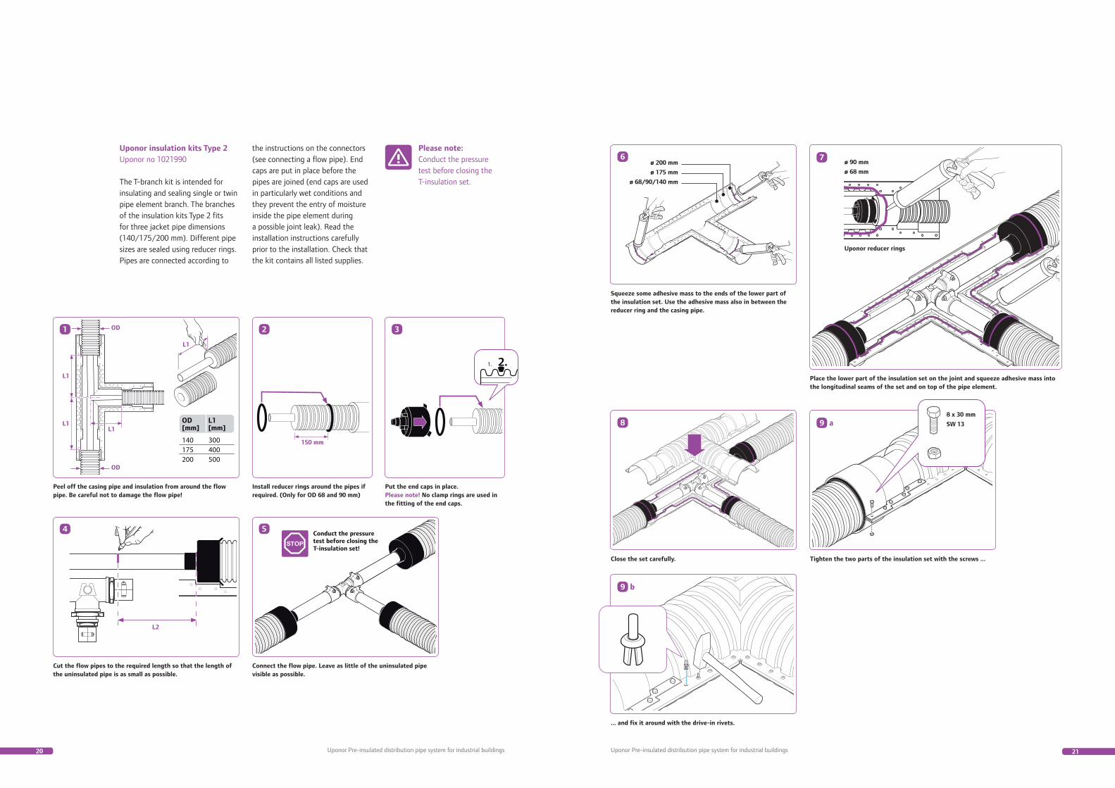
Squeeze some adhesive mass to the ends of the lower part of the insulation set. Use the adhesive mass also in between the reducer ring and the casing pipe.
Place the lower part of the insulation set on the joint and squeeze adhesive mass into the longitudinal seams of the set and on top of the pipe element.
Close the set carefully.
... and fix it around with the drive-in rivets.
Tighten the two parts of the insulation set with the screws ...
Uponor insulation kits Type 2Uponor no 1021990
The T-branch kit is intended for insulating and sealing single or twin pipe element branch. The branches of the insulation kits Type 2 fits for three jacket pipe dimensions (140/175/200 mm). Different pipe sizes are sealed using reducer rings. Pipes are connected according to
the instructions on the connectors (see connecting a flow pipe). End caps are put in place before the pipes are joined (end caps are used in particularly wet conditions and they prevent the entry of moisture inside the pipe element during a possible joint leak). Read the installation instructions carefully prior to the installation. Check that the kit contains all listed supplies.
Please note:Conduct the pressure test before closing the T-insulation set.
Peel off the casing pipe and insulation from around the flow pipe. Be careful not to damage the flow pipe!
Install reducer rings around the pipes ifrequired. (Only for OD 68 and 90 mm)
Put the end caps in place.Please note! No clamp rings are used inthe fitting of the end caps.
Cut the flow pipes to the required length so that the length ofthe uninsulated pipe is as small as possible.
Connect the flow pipe. Leave as little of the uninsulated pipevisible as possible.

22 23
20mm
Pressure test
8
7
6
5
4
3
2
1
Uponor Pre-insulated distribution pipe system for industrial buildings Uponor Pre-insulated distribution pipe system for industrial buildings
Peel off the jacket and insulation from around the flow pipes.
Be careful not to damage the flow pipe! Put the end caps in place before joining the flow pipes. Please note! No clamp rings are used in the fi tting of the end caps.
Cut the ends of the flow pipes to the required length so that the length of the uninsulated pipe is as small as possible.
Connect the flow pipe. Leave as little of the uninsulated pipe as visible as possible.
Please note: conduct a pressure test before closing the extension kit.
Squeeze some adhesive mass to the ends of the lower part of the insulation chute.
Mount the lower part of the insulation chute on the joint. Squeeze some adhesive mass into the longitudinal seams of the chute and on top of the pipe element.
Close the chute carefully. Tighten the hose clamps around the insulation kit in the marked places and tighten until the ends of the clamp are 20 mm apart. Use oil to lubricate the hose clamp screw.
Installing the extension The extension kit is intended for insulating and sealing a level single or twin pipe element extension. Pipes are joined with connectors according to the instructions (see connecting a fl ow pipe). End caps are put in place before joining the pipes (end caps are used in particularly moist conditions and they prevent moisture from entering the pipe element in case of a possible connector leak). Read the installation instructions carefully prior to the installation. Check that the kit contains all listed supplies.
Extension
T-branch insulation set
Contents of the kit Required tools
Extension insulation chute, one piece
Hose clamps for closing the insulation
chutes 6 pcs
Polyurethane adhesive mass, one
piece
Saw for cutting the pipe
A sharp knife
Hex wrench for tightening the hose
clamps
Sealant massgun
Please note:Conduct the pressure test before the extension insulation kit is closed.
The pressure test is carried out before closing the wells and installing the insulation kits. In an ordinary seal test, the water pressure makes a fl exible plastic pipe expand, which demonstrates as a drop of pressure in the gauge. It may take up to 24 h before the pressure levels out and sealing can be determined. A fast test method intended for use with plastic pipes shows the sealing of the pipes in just a couple of hours.
Testing system
Fill the system with water and deaerate it. Ensure that the equipment connected to the piping can withstand the test pressure. If required, seal them off the pressure test.
Increase the pressure to 1.5 x working pressure. Retain the pressure on this level for half an hour by adding water as the piping expands.
Then drain the water quickly until the pressure has fallen to about one half of the working pressure. Close the discharge valve.
In a sealed piping, the pressure will increase to a stable value in a few minutes, for example in a 10 bar network from 5 bar to approximately 5.5 bar.
Monitor the pressure level for 1½ hours. If pressure does not fall during this time, the system is sealed. The slightest leak is immediately visible from the pressure gauge.
5
4
3
2
1
Pressure test for the pipeline
24 25Uponor Pre-insulated distribution pipe system for industrial buildings Uponor Pre-insulated distribution pipe system for industrial buildings
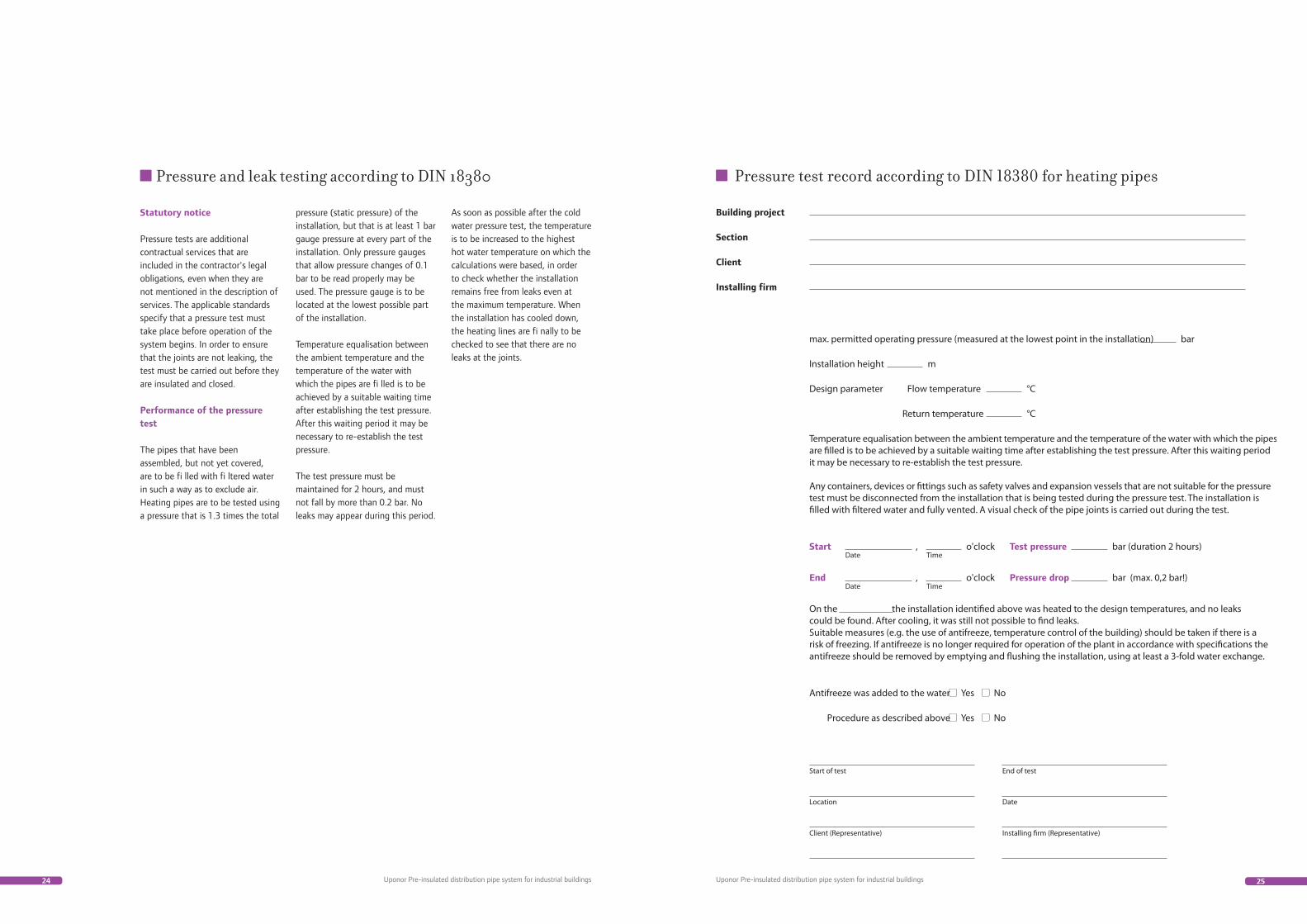
Statutory notice
Pressure tests are additional contractual services that are included in the contractor's legal obligations, even when they are not mentioned in the description of services. The applicable standards specify that a pressure test must take place before operation of the system begins. In order to ensure that the joints are not leaking, the test must be carried out before they are insulated and closed.
Performance of the pressure test
The pipes that have been assembled, but not yet covered, are to be fi lled with fi ltered water in such a way as to exclude air. Heating pipes are to be tested using a pressure that is 1.3 times the total
pressure (static pressure) of the installation, but that is at least 1 bar gauge pressure at every part of the installation. Only pressure gauges that allow pressure changes of 0.1 bar to be read properly may be used. The pressure gauge is to be located at the lowest possible part of the installation.
Temperature equalisation between the ambient temperature and the temperature of the water with which the pipes are fi lled is to be achieved by a suitable waiting time after establishing the test pressure. After this waiting period it may be necessary to re-establish the test pressure.
The test pressure must be maintained for 2 hours, and must not fall by more than 0.2 bar. No leaks may appear during this period.
As soon as possible after the cold water pressure test, the temperature is to be increased to the highest hot water temperature on which the calculations were based, in order to check whether the installation remains free from leaks even at the maximum temperature. When the installation has cooled down, the heating lines are fi nally to be checked to see that there are no leaks at the joints.
Pressure and leak testing according to DIN 18380
26 27Uponor Pre-insulated distribution pipe system for industrial buildings Uponor Pre-insulated distribution pipe system for industrial buildings
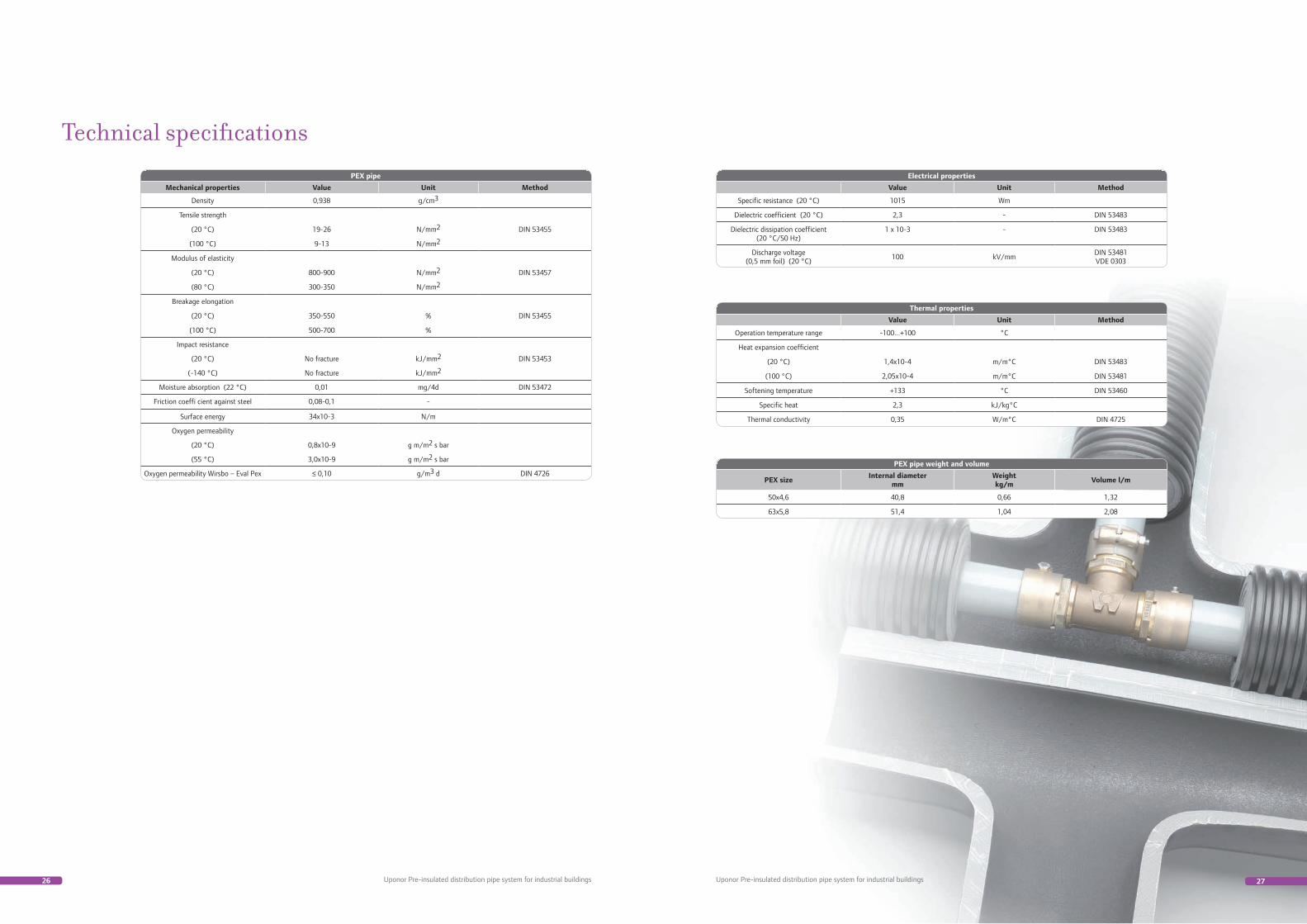
PEX pipe
Mechanical properties Value Unit Method
Density 0,938 g/cm3
Tensile strength
(20 °C) 19-26 N/mm2 DIN 53455
(100 °C) 9-13 N/mm2
Modulus of elasticity
(20 °C) 800-900 N/mm2 DIN 53457
(80 °C) 300-350 N/mm2
Breakage elongation
(20 °C) 350-550 % DIN 53455
(100 °C) 500-700 %
Impact resistance
(20 °C) No fracture kJ/mm2 DIN 53453
(-140 °C) No fracture kJ/mm2
Moisture absorption (22 °C) 0,01 mg/4d DIN 53472
Friction coeffi cient against steel 0,08-0,1 -
Surface energy 34x10-3 N/m
Oxygen permeability
(20 °C) 0,8x10⁻⁹ g m/m2 s bar
(55 °C) 3,0x10⁻⁹ g m/m2 s bar
Oxygen permeability Wirsbo – Eval Pex ≤ 0,10 g/m3 d DIN 4726
Electrical properties
Value Unit Method
Specific resistance (20 °C) 1015 Wm
Dielectric coefficient (20 °C) 2,3 - DIN 53483
Dielectric dissipation coefficient (20 °C/50 Hz)
1 x 10⁻³ - DIN 53483
Discharge voltage(0,5 mm foil) (20 °C)
100 kV/mmDIN 53481VDE 0303
Thermal properties
Value Unit Method
Operation temperature range -100...+100 °C
Heat expansion coefficient
(20 °C) 1,4x10⁻⁴ m/m°C DIN 53483
(100 °C) 2,05x10⁻⁴ m/m°C DIN 53481
Softening temperature +133 °C DIN 53460
Specific heat 2,3 kJ/kg°C
Thermal conductivity 0,35 W/m°C DIN 4725
Technical specifications
PEX pipe weight and volume
PEX sizeInternal diameter
mmWeightkg/m
Volume l/m
50x4,6 40,8 0,66 1,32
63x5,8 51,4 1,04 2,08
28 29Uponor Pre-insulated distribution pipe system for industrial buildings Uponor Pre-insulated distribution pipe system for industrial buildings
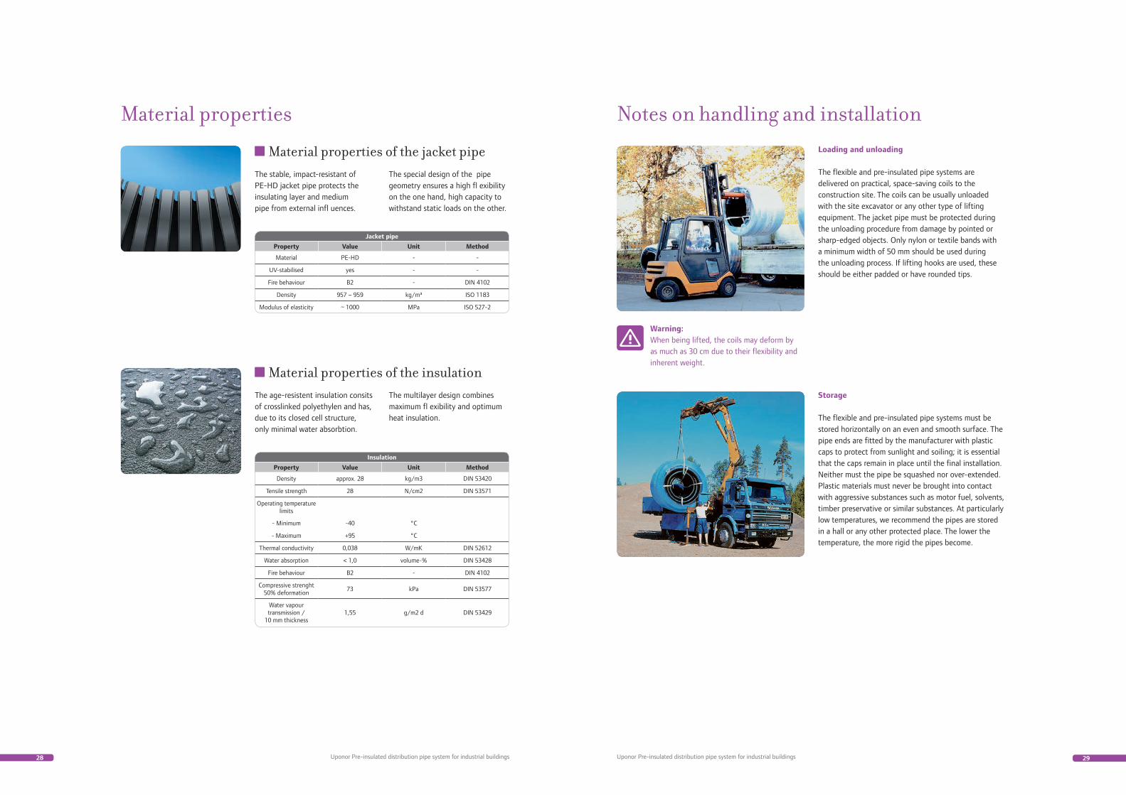
Material properties
Material properties of the jacket pipe
Jacket pipe
Property Value Unit Method
Material PE-HD - -
UV-stabilised yes - -
Fire behaviour B2 - DIN 4102
Density 957 – 959 kg/m³ ISO 1183
Modulus of elasticity ~ 1000 MPa ISO 527-2
The stable, impact-resistant of PE-HD jacket pipe protects the insulating layer and medium pipe from external infl uences.
The special design of the pipe geometry ensures a high fl exibility on the one hand, high capacity to withstand static loads on the other.
Material properties of the insulation
Insulation
Property Value Unit Method
Density approx. 28 kg/m3 DIN 53420
Tensile strength 28 N/cm2 DIN 53571
Operating temperature limits
- Minimum -40 °C
- Maximum +95 °C
Thermal conductivity 0,038 W/mK DIN 52612
Water absorption < 1,0 volume-% DIN 53428
Fire behaviour B2 - DIN 4102
Compressive strenght 50% deformation
73 kPa DIN 53577
Water vapour transmission /
10 mm thickness1,55 g/m2 d DIN 53429
The age-resistent insulation consits of crosslinked polyethylen and has, due to its closed cell structure, only minimal water absorbtion.
The multilayer design combines maximum fl exibility and optimum heat insulation.
Notes on handling and installationLoading and unloading The flexible and pre-insulated pipe systems are delivered on practical, space-saving coils to the construction site. The coils can be usually unloaded with the site excavator or any other type of lifting equipment. The jacket pipe must be protected during the unloading procedure from damage by pointed or sharp-edged objects. Only nylon or textile bands with a minimum width of 50 mm should be used during the unloading process. If lifting hooks are used, these should be either padded or have rounded tips.
Storage The flexible and pre-insulated pipe systems must be stored horizontally on an even and smooth surface. The pipe ends are fitted by the manufacturer with plastic caps to protect from sunlight and soiling; it is essential that the caps remain in place until the final installation. Neither must the pipe be squashed nor over-extended. Plastic materials must never be brought into contact with aggressive substances such as motor fuel, solvents, timber preservative or similar substances. At particularly low temperatures, we recommend the pipes are stored in a hall or any other protected place. The lower the temperature, the more rigid the pipes become.
Warning:When being lifted, the coils may deform by as much as 30 cm due to their flexibility and inherent weight.
30 31Uponor Pre-insulated distribution pipe system for industrial buildings Uponor Pre-insulated distribution pipe system for industrial buildings
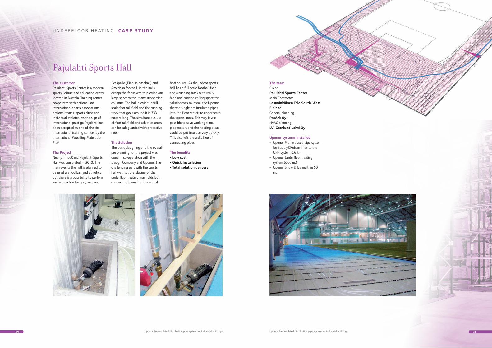
Pajulahti Sports HallThe customerPajulahti Sports Center is a modern sports, leisure and education center located in Nastola. Training center cooperates with national and international sports associations, national teams, sports clubs and individual athletes. As the sign of international prestige Pajulahti has been accepted as one of the six international training centers by the International Wrestling Federation FILA.
The ProjectNearly 11.000 m2 Pajulahti Sports Hall was completed in 2010. The main events the hall is planned to be used are football and athletics but there is a possibility to perform winter practice for golf, archery,
Pesäpallo (Finnish baseball) and American football. In the halls design the focus was to provide one large space without any supporting columns. The hall provides a full scale football field and the running track that goes around it is 333 meters long. The simultaneous use of football field and athletics areas can be safeguarded with protective nets.
The SolutionThe basic designing and the overall pre planning for the project was done in co-operation with the Design Company and Uponor. The challenging part with the sports hall was not the placing of the underfloor heating manifolds but connecting them into the actual
heat source. As the indoor sports hall has a full scale football field and a running track with really high and curving ceiling space the solution was to install the Uponor thermo single pre insulated pipes into the floor structure underneath the sports areas. This way it was possible to save working time, pipe meters and the heating areas could be put into use very quickly. This also left the walls free of connecting pipes.
The benefits- Low cost- Quick Installation- Total solution delivery
U N D E R F LO O R H E AT I N G C A S E ST U DY
The teamClient Pajulahti Sports CenterMain Contractor Lemminkäinen Talo South-West FinlandGeneral planning ProArk OyHVAC planning LVI Granlund Lahti Oy
Uponor systems installed- Uponor Pre Insulated pipe system for Supply&Return lines to the UFH system 0,6 km- Uponor Underfloor heating system 6000 m2- Uponor Snow & Ice melting 50 m2

Uponor CorporationRobert Huberin tie 3 BFIN-01511 VANTAAFinland+358 20 129 211www.uponor.com
Pre-
insu
late
d di
strib
utio
n pi
pe s
yste
m fo
r ind
ustr
ial b
uild
ings
02/
2011
Uponor offers construction professionals uncompromising quality, leadingedge expertise and long-lasting partnerships. As a leading international company, we are known for our solutions that help create better human environments.
Uponor’s Simply More philosophy includes services for all stages of the construction process – from the fi rst concept of a project to a building in use.