Embed Size (px)
Citation preview

1
Read all instructions before proceeding with installation.
UpgradeInstallation Instructions

2
3
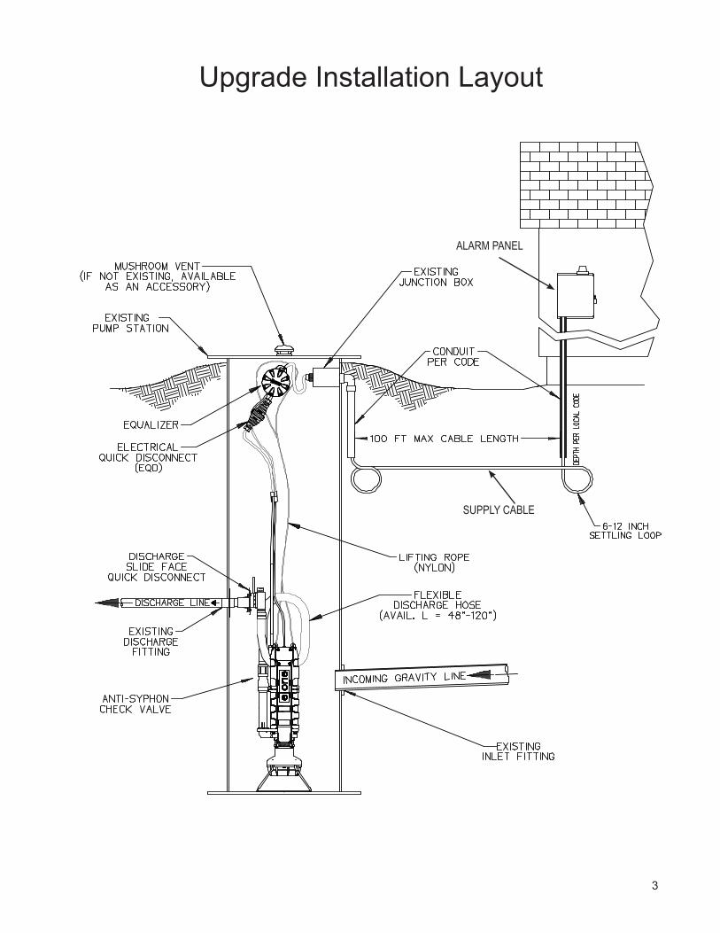
Upgrade Installation Layout
ALARM PANEL
SUPPLY CABLE

4
The Environment One Upgrade is a well-engineered, reliable and proven product; proper installation will ensure years of trouble-free service. The Upgrade is designed to replace a troublesome grinder pump in a residential or light commercial sewage handling application.
Read all instructions before starting unit replacement. If you have any questions, call your local distributor or Environment One for assistance at (518) 346-6161.
This is a sewage handling pump and must be vented in accordance with local plumbing codes. This pump is not to be installed in locations classified as hazardous in accordance with National Electric Code, ANSI/NFPA 70. All piping and electrical systems must be in compliance with applicable local and state codes.
Note: Occupational Safety and Health Standard (OSHA) mandates that anyone entering a confined space (such as sewage tank, manhole, septic tank, etc.) must follow the confined spaces rules and regulations. This can be found in Code of Federal Regulations Book 29, Section 1910.146, distributed by OSHA. This gives guidelines on how to safely enter tanks to make needed changes or repairs. If possible, make all changes without entering the tank.
Before beginning unit replacement, unpack hardware to ensure all items needed to complete the installation are accounted for. Inspect station to see if additional items not supplied by Environment One will be needed to complete the job, such as plumbing hardware kit, replacement tank, special tools, electrical hardware, etc.
Preparation of Tank
1. Instruct homeowner to cease water usage.2. Remove tank lid.3. Inspect lid integrity:
• Clean all debris from lid• Inspect lid to ensure it is capable of supporting loads it may encounter (people, lawn tractor, trailer,
etc.).• Inspect to ensure that lid can be sealed to prevent ground water infiltration. Note: If tank lid is deficient
in any way, replace it.4. Wash tank wall, rail assembly, pump and tank floor using a high-pressure water line.5. Use existing grinder unit to pump down to “off” level. If manual-run is available, use it to pump tank down
to lowest level possible.6. Turn off all electrical power to old control panel at main house supply. Test with voltmeter, at panel, to
ensure all power is off.7. Close curb stop or discharge valve at street.8. Disconnect and remove float assembly from tank.9. Remove existing pump from tank.10. Remove rail assembly and discharge assembly.11. Remove all remaining brackets in tank that are not pertinent to tank structure. This can be accomplished
by making an extension wrench out of a metal rod that is long enough to reach the bottom of the tank. 12. Pump out remaining sewage and debris from tank. Clean tank floor.13. Seal all holes in tank interior left by the removal of hardware in the tank.14. Inspect tank interior for structural integrity and leak tightness. Failure to prevent all infiltration may
cause premature pump failure and void warranty.15. Disconnect the power and remove the existing alarm/disconnect panel.16. Grade around the tank to prevent ground water infiltration during heavy rain.
5
Installing the Upgrade Pump
1. Unpack all materials. Warranty registration and user instructions must be given to the owner. Hardware packed with the unit will be used during installation.
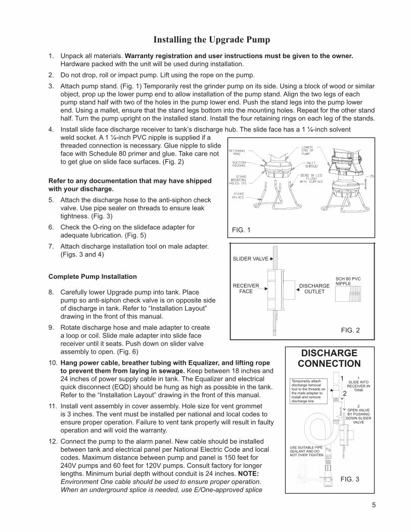
2. Do not drop, roll or impact pump. Lift using the rope on the pump.3. Attach pump stand. (Fig. 1) Temporarily rest the grinder pump on its side. Using a block of wood or similar
object, prop up the lower pump end to allow installation of the pump stand. Align the two legs of each pump stand half with two of the holes in the pump lower end. Push the stand legs into the pump lower end. Using a mallet, ensure that the stand legs bottom into the mounting holes. Repeat for the other stand half. Turn the pump upright on the installed stand. Install the four retaining rings on each leg of the stands.
4. Install slide face discharge receiver to tank’s discharge hub. The slide face has a 1 ¼-inch solvent weld socket. A 1 ¼-inch PVC nipple is supplied if a threaded connection is necessary. Glue nipple to slide face with Schedule 80 primer and glue. Take care not to get glue on slide face surfaces. (Fig. 2)
Refer to any documentation that may have shipped with your discharge.5. Attach the discharge hose to the anti-siphon check
valve. Use pipe sealer on threads to ensure leak tightness. (Fig. 3)
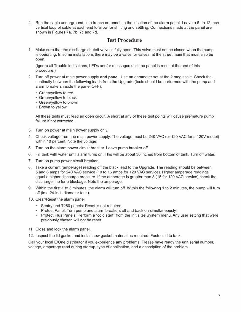
6. Check the O-ring on the slideface adapter for adequate lubrication. (Fig. 5)
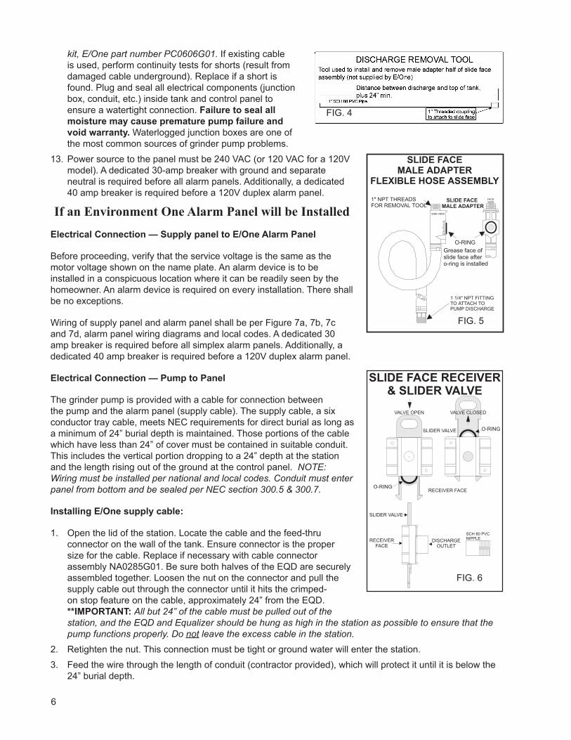
7. Attach discharge installation tool on male adapter. (Figs. 3 and 4)
Complete Pump Installation
8. Carefully lower Upgrade pump into tank. Place pump so anti-siphon check valve is on opposite side of discharge in tank. Refer to “Installation Layout” drawing in the front of this manual.
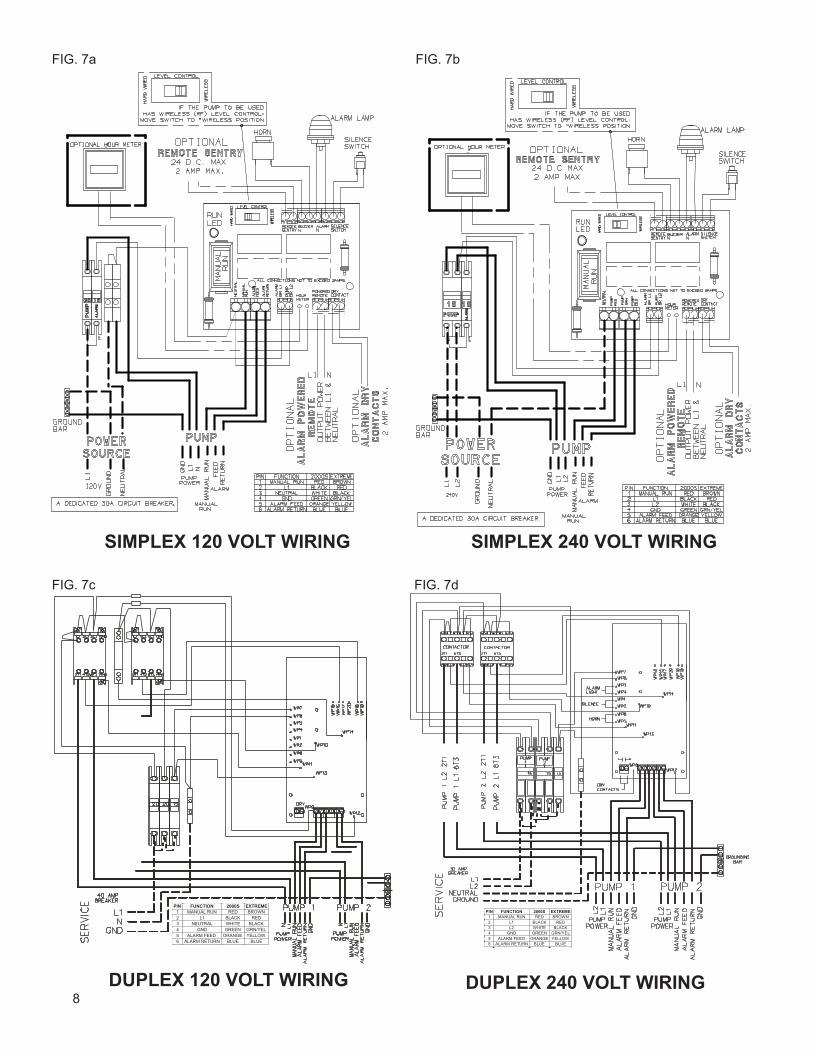
9. Rotate discharge hose and male adapter to create a loop or coil. Slide male adapter into slide face receiver until it seats. Push down on slider valve assembly to open. (Fig. 6)
10. Hang power cable, breather tubing with Equalizer, and lifting rope to prevent them from laying in sewage. Keep between 18 inches and 24 inches of power supply cable in tank. The Equalizer and electrical quick disconnect (EQD) should be hung as high as possible in the tank. Refer to the “Installation Layout” drawing in the front of this manual.
11. Install vent assembly in cover assembly. Hole size for vent grommet is 3 inches. The vent must be installed per national and local codes to ensure proper operation. Failure to vent tank properly will result in faulty operation and will void the warranty.
12. Connect the pump to the alarm panel. New cable should be installed between tank and electrical panel per National Electric Code and local codes. Maximum distance between pump and panel is 150 feet for 240V pumps and 60 feet for 120V pumps. Consult factory for longer lengths. Minimum burial depth without conduit is 24 inches. NOTE: Environment One cable should be used to ensure proper operation. When an underground splice is needed, use E/One-approved splice
FIG. 2
FIG. 3
FIG. 1
6
kit, E/One part number PC0606G01. If existing cable is used, perform continuity tests for shorts (result from damaged cable underground). Replace if a short is found. Plug and seal all electrical components (junction box, conduit, etc.) inside tank and control panel to ensure a watertight connection. Failure to seal all moisture may cause premature pump failure and void warranty. Waterlogged junction boxes are one of the most common sources of grinder pump problems.
13. Power source to the panel must be 240 VAC (or 120 VAC for a 120V model). A dedicated 30-amp breaker with ground and separate neutral is required before all alarm panels. Additionally, a dedicated 40 amp breaker is required before a 120V duplex alarm panel.
If an Environment One Alarm Panel will be Installed
Electrical Connection — Supply panel to E/One Alarm Panel
Before proceeding, verify that the service voltage is the same as the motor voltage shown on the name plate. An alarm device is to be installed in a conspicuous location where it can be readily seen by the homeowner. An alarm device is required on every installation. There shall be no exceptions.
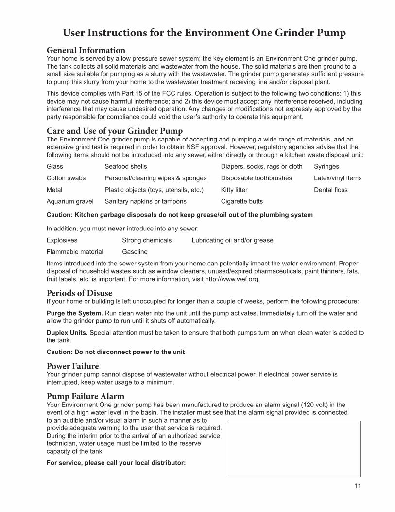
Wiring of supply panel and alarm panel shall be per Figure 7a, 7b, 7c and 7d, alarm panel wiring diagrams and local codes. A dedicated 30 amp breaker is required before all simplex alarm panels. Additionally, a dedicated 40 amp breaker is required before a 120V duplex alarm panel.
Electrical Connection — Pump to Panel
The grinder pump is provided with a cable for connection between the pump and the alarm panel (supply cable). The supply cable, a six conductor tray cable, meets NEC requirements for direct burial as long as a minimum of 24” burial depth is maintained. Those portions of the cable which have less than 24” of cover must be contained in suitable conduit. This includes the vertical portion dropping to a 24” depth at the station and the length rising out of the ground at the control panel. NOTE: Wiring must be installed per national and local codes. Conduit must enter panel from bottom and be sealed per NEC section 300.5 & 300.7.
Installing E/One supply cable:
1. Open the lid of the station. Locate the cable and the feed-thru connector on the wall of the tank. Ensure connector is the proper size for the cable. Replace if necessary with cable connector assembly NA0285G01. Be sure both halves of the EQD are securely assembled together. Loosen the nut on the connector and pull the supply cable out through the connector until it hits the crimped-on stop feature on the cable, approximately 24” from the EQD. **IMPORTANT: All but 24” of the cable must be pulled out of the station, and the EQD and Equalizer should be hung as high in the station as possible to ensure that the pump functions properly. Do not leave the excess cable in the station.
2. Retighten the nut. This connection must be tight or ground water will enter the station.3. Feed the wire through the length of conduit (contractor provided), which will protect it until it is below the
24” burial depth.
FIG. 4
FIG. 5
FIG. 6
7
4. Run the cable underground, in a trench or tunnel, to the location of the alarm panel. Leave a 6- to 12-inch vertical loop of cable at each end to allow for shifting and settling. Connections made at the panel are shown in Figures 7a, 7b, 7c and 7d.
Test Procedure
1. Make sure that the discharge shutoff valve is fully open. This valve must not be closed when the pump is operating. In some installations there may be a valve, or valves, at the street main that must also be open.
(Ignore all Trouble indications, LEDs and/or messages until the panel is reset at the end of this procedure.)
2. Turn off power at main power supply and panel. Use an ohmmeter set at the 2 meg scale. Check the continuity between the following leads from the Upgrade (tests should be performed with the pump and alarm breakers inside the panel OFF):• Green/yellow to red• Green/yellow to black• Green/yellow to brown• Brown to yellow
All these tests must read an open circuit. A short at any of these test points will cause premature pump failure if not corrected.
3. Turn on power at main power supply only.4. Check voltage from the main power supply. The voltage must be 240 VAC (or 120 VAC for a 120V model)
within 10 percent. Note the voltage.5. Turn on the alarm power circuit breaker. Leave pump breaker off. 6. Fill tank with water until alarm turns on. This will be about 30 inches from bottom of tank. Turn off water.7. Turn on pump power circuit breaker. 8. Take a current (amperage) reading off the black lead to the Upgrade. The reading should be between
5 and 8 amps for 240 VAC service (10 to 16 amps for 120 VAC service). Higher amperage readings equal a higher discharge pressure. If the amperage is greater than 8 (16 for 120 VAC service) check the discharge line for a blockage. Note the amperage.
9. Within the first 1 to 3 minutes, the alarm will turn off. Within the following 1 to 2 minutes, the pump will turn off (in a 24-inch diameter tank).
10. Clear/Reset the alarm panel:• Sentry and T260 panels: Reset is not required.• Protect Panel: Turn pump and alarm breakers off and back on simultaneously. • Protect Plus Panels: Perform a “cold start” from the Initialize System menu. Any user setting that were
previously chosen will not be reset.
11. Close and lock the alarm panel.12. Inspect the lid gasket and install new gasket material as required. Fasten lid to tank.Call your local E/One distributor if you experience any problems. Please have ready the unit serial number, voltage, amperage read during startup, type of application, and a description of the problem.
8DUPLEX 240 VOLT WIRING
SIMPLEX 240 VOLT WIRINGSIMPLEX 120 VOLT WIRING
DUPLEX 120 VOLT WIRING
FIG. 7a FIG. 7b
FIG. 7c FIG. 7d

9

10
Environment One Corporation2773 Balltown RoadNiskayuna, New York 12309–1090
Voice: (01) 518.346.6161Fax: 518.346.6188
www.eone.comNA0065P01 Rev. C
8/15
A Precision Castparts Company
11
User Instructions for the Environment One Grinder PumpGeneral InformationYour home is served by a low pressure sewer system; the key element is an Environment One grinder pump. The tank collects all solid materials and wastewater from the house. The solid materials are then ground to a small size suitable for pumping as a slurry with the wastewater. The grinder pump generates sufficient pressure to pump this slurry from your home to the wastewater treatment receiving line and/or disposal plant.
This device complies with Part 15 of the FCC rules. Operation is subject to the following two conditions: 1) this device may not cause harmful interference; and 2) this device must accept any interference received, including interference that may cause undesired operation. Any changes or modifications not expressly approved by the party responsible for compliance could void the user’s authority to operate this equipment.
Care and Use of your Grinder PumpThe Environment One grinder pump is capable of accepting and pumping a wide range of materials, and an extensive grind test is required in order to obtain NSF approval. However, regulatory agencies advise that the following items should not be introduced into any sewer, either directly or through a kitchen waste disposal unit:
Glass Seafood shells Diapers, socks, rags or cloth Syringes
Cotton swabs Personal/cleaning wipes & sponges Disposable toothbrushes Latex/vinyl items
Metal Plastic objects (toys, utensils, etc.) Kitty litter Dental floss
Aquarium gravel Sanitary napkins or tampons Cigarette butts
Caution: Kitchen garbage disposals do not keep grease/oil out of the plumbing system
In addition, you must never introduce into any sewer:
Explosives Strong chemicals Lubricating oil and/or grease
Flammable material Gasoline
Items introduced into the sewer system from your home can potentially impact the water environment. Proper disposal of household wastes such as window cleaners, unused/expired pharmaceuticals, paint thinners, fats, fruit labels, etc. is important. For more information, visit http://www.wef.org.
Periods of DisuseIf your home or building is left unoccupied for longer than a couple of weeks, perform the following procedure:
Purge the System. Run clean water into the unit until the pump activates. Immediately turn off the water and allow the grinder pump to run until it shuts off automatically.
Duplex Units. Special attention must be taken to ensure that both pumps turn on when clean water is added to the tank.
Caution: Do not disconnect power to the unit
Power FailureYour grinder pump cannot dispose of wastewater without electrical power. If electrical power service is interrupted, keep water usage to a minimum.
Pump Failure AlarmYour Environment One grinder pump has been manufactured to produce an alarm signal (120 volt) in the event of a high water level in the basin. The installer must see that the alarm signal provided is connected to an audible and/or visual alarm in such a manner as to provide adequate warning to the user that service is required. During the interim prior to the arrival of an authorized service technician, water usage must be limited to the reserve capacity of the tank.
For service, please call your local distributor:

12
SEWER SYSTEMS
2773 Balltown Rd • Niskayuna NY USA 12309
(01) 518.346.6161 • www.eone.com
Environment One Corporation offers a limited warranty that guarantees its product to be free from defects in material and factory workmanship for a period of two years from the date of installation, or 27 months from the date of shipment, whichever occurs first, provided the product is properly installed, serviced and operated under normal conditions and according to manufacturer’s instructions. Repair or parts replacement required as a result of such defect will be made free of charge during this period upon return of the defective parts or equipment to the manufacturer or its nearest authorized service center.
Limited WarrantyFor E/One Extreme D-Series,
W-Series & Upgrade
Model Number: ______________________
Serial Number: _______________________
Installation Date: _____________________
E/One SewersTME/One Sewers TM