Embed Size (px)
Citation preview
Updates to
MVI Regulations Manual
• The newest version of the Missouri Motor Vehicle Safety Inspection Regulations manual is available electronically on the Motor Vehicle Inspection Section webpage, listed below.
https://apps.mshp.dps.mo.gov/MSHPWeb/PatrolDivisions/DVSD/MVI/FormsBrochures.html
This presentation provides an overview of the changes contained within the updated manual. New language is shown in bold print.
11 CSR 50-2.020: Minimum Inspection Station Requirements (Continued)
(1) Premises.
(A) Each inspection station must have an inspection area within an enclosed
building of sufficient length, width, and height to accommodate the type of vehicle
being inspected. Class A and D stations are required to accommodate a commercial
vehicle. Class B stations must accommodate a standard full-size passenger vehicle.
Class C stations are required to have sufficient length and width to inspect full-size
motorcycles.
1. In addition to an inside area, an outside area may be approved for-
a. Inspection of commercial vehicles at Class B stations; and
b. Inspection of motor tricycles and autocycles at Class C stations.
2. The area shall be substantially level and constructed of hard material, such as
asphalt or concrete. It shall be a part of and adjacent to the official vehicle inspection
station.
11 CSR 50-2.020: Minimum Inspection Station Requirements (Continued)
(2) Equipment.
(A) All inspection stations, except Class C, must have the following equipment which must be arranged and located at or near the inside inspection area:
1. Brake lining gauge. A gauge will be required to determine the remaining thickness in fractions of an inch of both bonded and riveted linings;
2. Brake pad gauge. Some type of gauging device to accurately measure the remaining thickness of the brake pad in fractions of an inch while the pad is within the caliper assembly;
3. Ball joint gauge. A ball joint gauge to accurately measure any looseness in the load-carrying ball joint. The gauge must be adapted to measure vertical (up and down) and horizontal (side-to-side) movement;
4. Lift or jack. A lift or jack, capable of hoisting a vehicle properly to check ball joints, suspension linkage and wheel play. If a lift is used, it must be the type which allows the front wheels to be suspended by lifting under the outer extremity of a motor vehicle’s lower control arm, cross member or frame;
11 CSR 50-2.020: Minimum Inspection Station Requirements (Continued)
5. Scraper. A scraper to remove old stickers;
6. Measuring device. Yardstick or steel tape preferred;
7. Punch. An open face paper punch with a round die to validate inspection stickers and decals;
8. A tire tread depth gauge which is graduated into one-thirty-second inch (1/32") increments must be part of the equipment at inspection stations that inspect school buses; and
9. A one-eighth inch (1/8") drawstring over thirty inches (30") in length with a one-half inch (1/2") hex nut attached to one (1) end to check handrails is required if the station will be inspecting school buses.
11 CSR 50-2.020: Minimum Inspection Station Requirements (Continued)
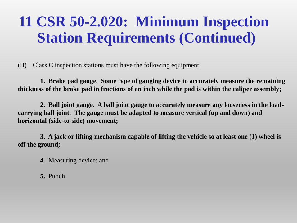
(B) Class C inspection stations must have the following equipment:
1. Brake pad gauge. Some type of gauging device to accurately measure the remaining
thickness of the brake pad in fractions of an inch while the pad is within the caliper assembly;
2. Ball joint gauge. A ball joint gauge to accurately measure any looseness in the load-
carrying ball joint. The gauge must be adapted to measure vertical (up and down) and
horizontal (side-to-side) movement;
3. A jack or lifting mechanism capable of lifting the vehicle so at least one (1) wheel is
off the ground;
4. Measuring device; and
5. Punch
11 CSR 50-2.030: Inspection Station Classification
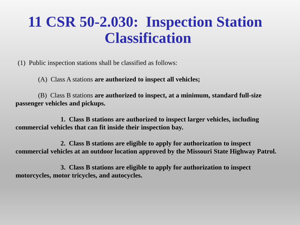
(1) Public inspection stations shall be classified as follows:
(A) Class A stations are authorized to inspect all vehicles;
(B) Class B stations are authorized to inspect, at a minimum, standard full-size
passenger vehicles and pickups.
1. Class B stations are authorized to inspect larger vehicles, including
commercial vehicles that can fit inside their inspection bay.
2. Class B stations are eligible to apply for authorization to inspect
commercial vehicles at an outdoor location approved by the Missouri State Highway Patrol.
3. Class B stations are eligible to apply for authorization to inspect
motorcycles, motor tricycles, and autocycles.
11 CSR 50-2.030: Inspection Station Classification (Continued)
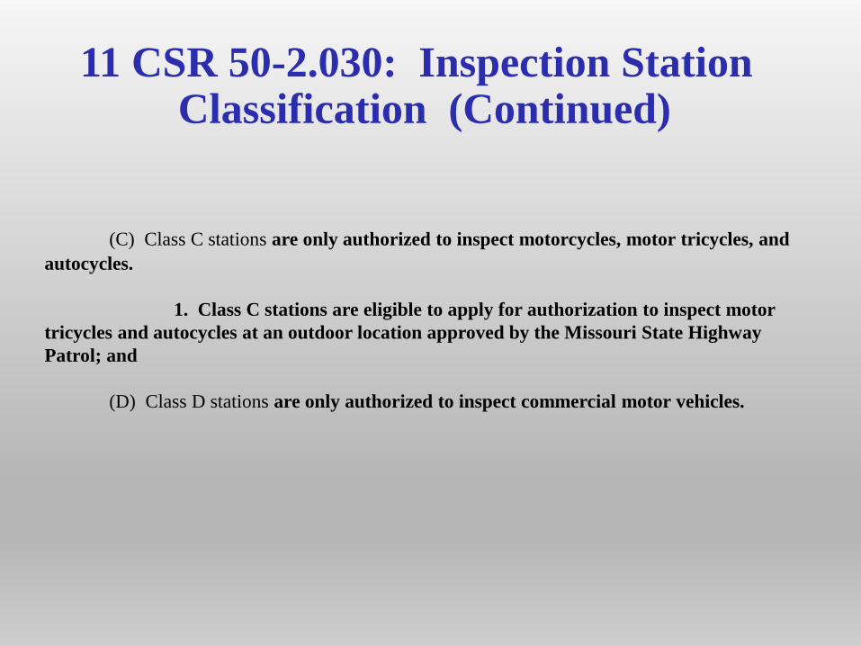
(C) Class C stations are only authorized to inspect motorcycles, motor tricycles, and
autocycles.
1. Class C stations are eligible to apply for authorization to inspect motor
tricycles and autocycles at an outdoor location approved by the Missouri State Highway
Patrol; and
(D) Class D stations are only authorized to inspect commercial motor vehicles.
11 CSR 50-2.080: Licensing of Inspector/Mechanics
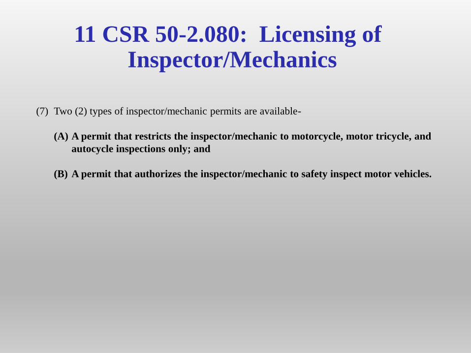
(7) Two (2) types of inspector/mechanic permits are available-
(A) A permit that restricts the inspector/mechanic to motorcycle, motor tricycle, and
autocycle inspections only; and
(B) A permit that authorizes the inspector/mechanic to safety inspect motor vehicles.
11 CSR 50-2.090: Inspection Station Operational Requirements
(2) All inspections must be conducted at the inspection station in the approved inside
inspection area, except that large commercial vehicles, motor tricycles, and
autocycles unable to fit within the approved inside inspection area may be inspected in
an approved outside inspection area during good weather only
11 CSR 50-2.160: Brake Components
(2) Drums, Discs, and Internal Brake Components. At least one (1) front or one (1) rear wheel and
drum must be removed on each passenger vehicle, one-half (1/2) ton and three-quarter (3/4) ton
pickup trucks, or similar type vehicles not equipped with dual rear wheels. Only the wheel must be
removed on vehicles equipped with disc brakes. Identification marks shall be made on the wheel and
lug before removal so the wheel can be remounted in the same position to insure wheel balance. On
drum brake systems, a new cotter pin must always be used when remounting a wheel and drum. The
removal of a wheel and/or drum is not required if the brake performance test has been administered
using an approved computerized brake testing machine. When an approved computerized brake
testing machine is used, and no wheel is removed, the inspector shall mark through the space on the
MVI-2 form provided for “Brake Inspected” with the letters “CBTM.” When removal of a wheel is
required, a wheel appearing to leak brake fluid or grease, shall be the wheel removed to inspect for
contamination. Wheels on four- (4-) wheel drive vehicles equipped exclusively with drum-type
brakes are not required to be removed.
(A) Inspect drums, discs, calipers, linings, pads, wheel cylinders, hoses, lines, and other
internal brake components.
1. Reject vehicle if-
A. There are substantial cracks on the friction surface extending to open
edge of drum or to the edge of a disc;
11 CSR 50-2.160: Brake Components
(CONTINUED)
B. A brake drum or disc has external cracks;
C. Friction surface of disc brake pads, rotor, brake linings, or brake drum is
contaminated with oil, grease, or brake fluid;
D. A brake lining is worn into the friction surface of the brake drum where the
brake drum cannot be removed after loosening the adjusting screw (backing off of the self-adjusting
mechanism);
E. Thinnest point of bonded lining is less than two thirty-seconds inch (2/32”);
F. Rivets are loose or missing or if lining or pad is not firmly attached to shoe;
G. Riveted lining is worn to less than two thirty-seconds inch (2//32”) above any
rivet head at thinnest point;
H. Wire is visible on the friction surface of wire-backed linings;
I. Lining is broken or cracked, does not include heat cracks;
J. A primary or secondary shoe and lining is improperly installed;
11 CSR 50-2.160: Brake Components
(CONTINUED)K. Bonded pads are worn at any one (1) point to less than two thirty-seconds inch
(2/32”);
L. Riveted pads are worn at any one (1) point to less than six thirty-seconds inch
(6/32”). If unable to determine if pads are riveted or bonded, pads will be considered to be bonded
pads.
M. A wheel cylinder or caliper leaks a sufficient amount of hydraulic fluid to cause
droplets. Do not mistake assembly fluid for hydraulic fluid;
N. Hoses or tubing leak or are cracked, chafed, flattened, restricted, bubbled,
improperly installed, or insecurely fastened;
O. Mechanical parts are missing, broken, or badly worn;
P. There is excessive friction in brake pedal, linkage, or other components;
Q. Pedal levers are improperly positioned or misaligned; or
R. Brake components are misaligned, binding, obstructed, or will not function
properly.
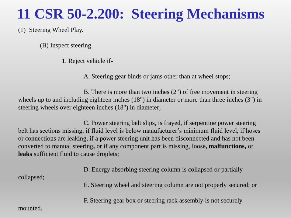
11 CSR 50-2.200: Steering Mechanisms(1) Steering Wheel Play.
(B) Inspect steering.
1. Reject vehicle if-
A. Steering gear binds or jams other than at wheel stops;
B. There is more than two inches (2") of free movement in steering
wheels up to and including eighteen inches (18") in diameter or more than three inches (3") in
steering wheels over eighteen inches (18") in diameter;
C. Power steering belt slips, is frayed, if serpentine power steering
belt has sections missing, if fluid level is below manufacturer’s minimum fluid level, if hoses
or connections are leaking, if a power steering unit has been disconnected and has not been
converted to manual steering, or if any component part is missing, loose, malfunctions, or
leaks sufficient fluid to cause droplets;
D. Energy absorbing steering column is collapsed or partially
collapsed;
E. Steering wheel and steering column are not properly secured; or
F. Steering gear box or steering rack assembly is not securely
mounted.
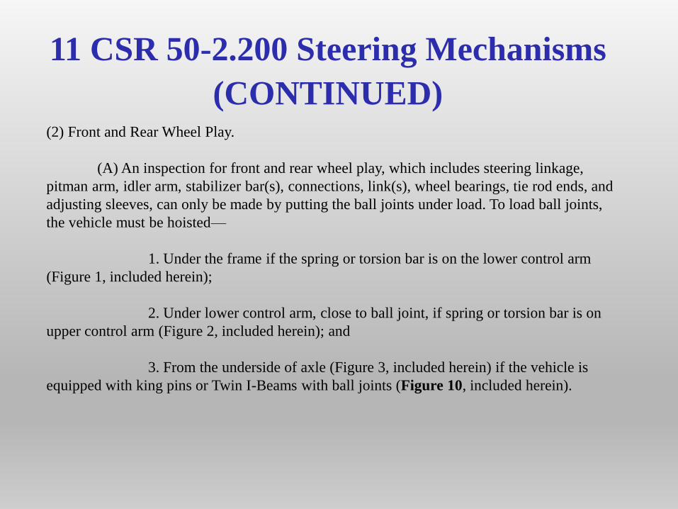
11 CSR 50-2.200 Steering Mechanisms
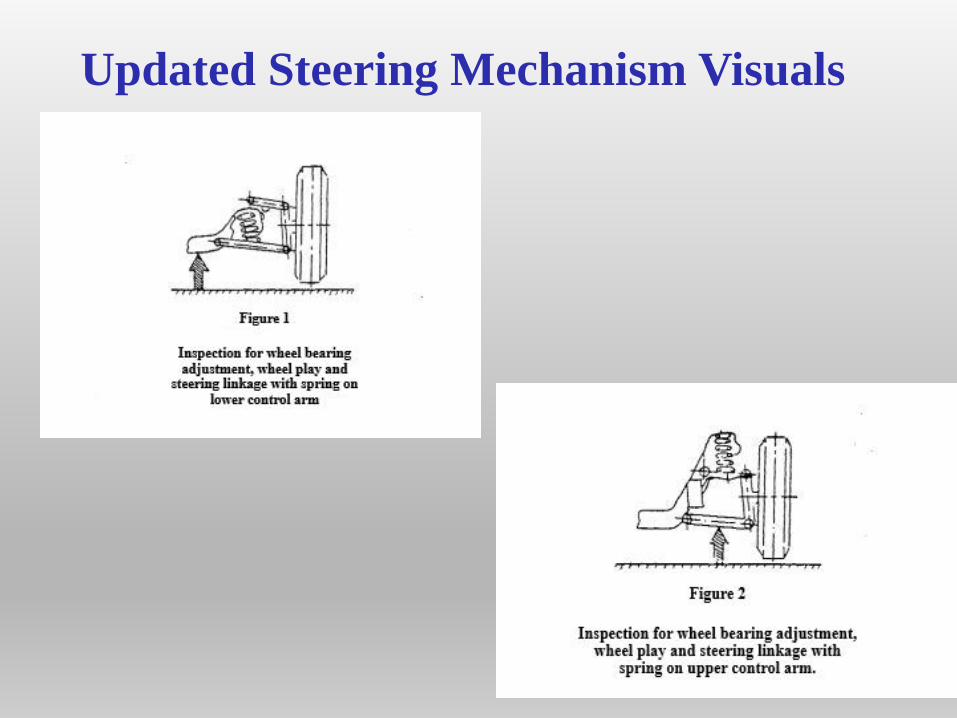
(CONTINUED)(2) Front and Rear Wheel Play.
(A) An inspection for front and rear wheel play, which includes steering linkage,
pitman arm, idler arm, stabilizer bar(s), connections, link(s), wheel bearings, tie rod ends, and
adjusting sleeves, can only be made by putting the ball joints under load. To load ball joints,
the vehicle must be hoisted—
1. Under the frame if the spring or torsion bar is on the lower control arm
(Figure 1, included herein);
2. Under lower control arm, close to ball joint, if spring or torsion bar is on
upper control arm (Figure 2, included herein); and
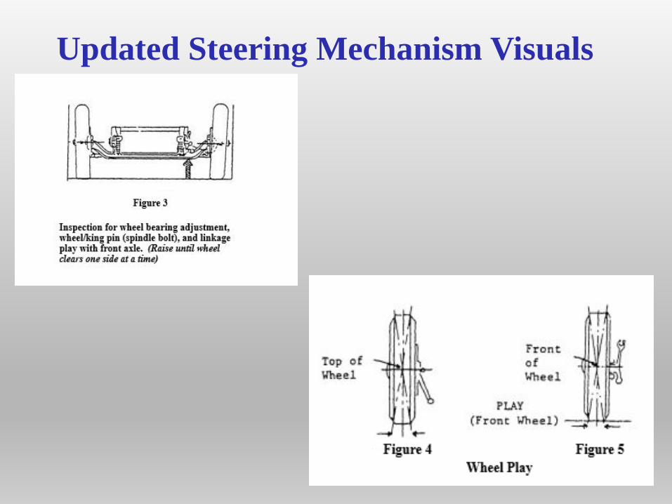
3. From the underside of axle (Figure 3, included herein) if the vehicle is
equipped with king pins or Twin I-Beams with ball joints (Figure 10, included herein).
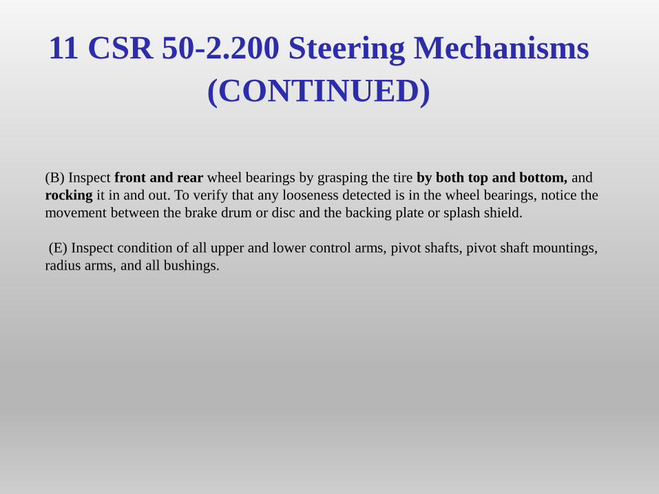
11 CSR 50-2.200 Steering Mechanisms
(CONTINUED)
(B) Inspect front and rear wheel bearings by grasping the tire by both top and bottom, and
rocking it in and out. To verify that any looseness detected is in the wheel bearings, notice the
movement between the brake drum or disc and the backing plate or splash shield.
(E) Inspect condition of all upper and lower control arms, pivot shafts, pivot shaft mountings,
radius arms, and all bushings.
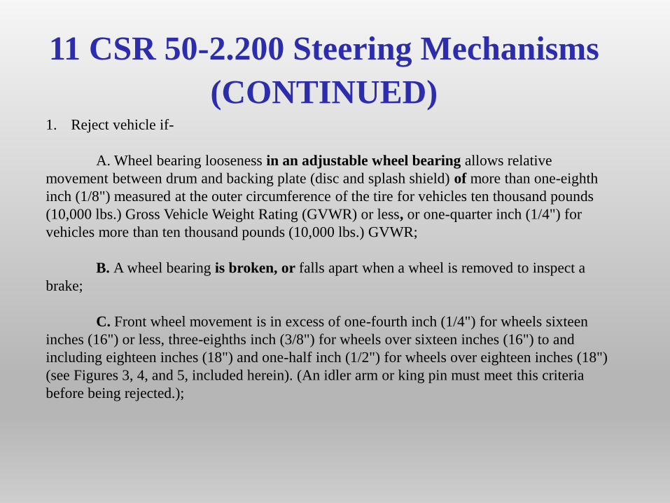
11 CSR 50-2.200 Steering Mechanisms
(CONTINUED)1. Reject vehicle if-
A. Wheel bearing looseness in an adjustable wheel bearing allows relative
movement between drum and backing plate (disc and splash shield) of more than one-eighth
inch (1/8") measured at the outer circumference of the tire for vehicles ten thousand pounds
(10,000 lbs.) Gross Vehicle Weight Rating (GVWR) or less, or one-quarter inch (1/4") for
vehicles more than ten thousand pounds (10,000 lbs.) GVWR;
B. A wheel bearing is broken, or falls apart when a wheel is removed to inspect a
brake;
C. Front wheel movement is in excess of one-fourth inch (1/4") for wheels sixteen
inches (16") or less, three-eighths inch (3/8") for wheels over sixteen inches (16") to and
including eighteen inches (18") and one-half inch (1/2") for wheels over eighteen inches (18")
(see Figures 3, 4, and 5, included herein). (An idler arm or king pin must meet this criteria
before being rejected.);
11 CSR 50-2.200 Steering Mechanisms
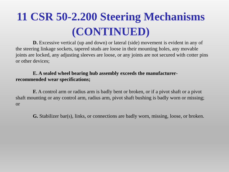
(CONTINUED)D. Excessive vertical (up and down) or lateral (side) movement is evident in any of
the steering linkage sockets, tapered studs are loose in their mounting holes, any movable
joints are locked, any adjusting sleeves are loose, or any joints are not secured with cotter pins
or other devices;
E. A sealed wheel bearing hub assembly exceeds the manufacturer-
recommended wear specifications;
F. A control arm or radius arm is badly bent or broken, or if a pivot shaft or a pivot
shaft mounting or any control arm, radius arm, pivot shaft bushing is badly worn or missing;
or
G. Stabilizer bar(s), links, or connections are badly worn, missing, loose, or broken.
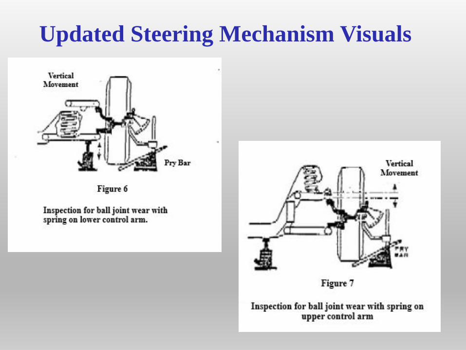
11 CSR 50-2.200 Steering Mechanisms
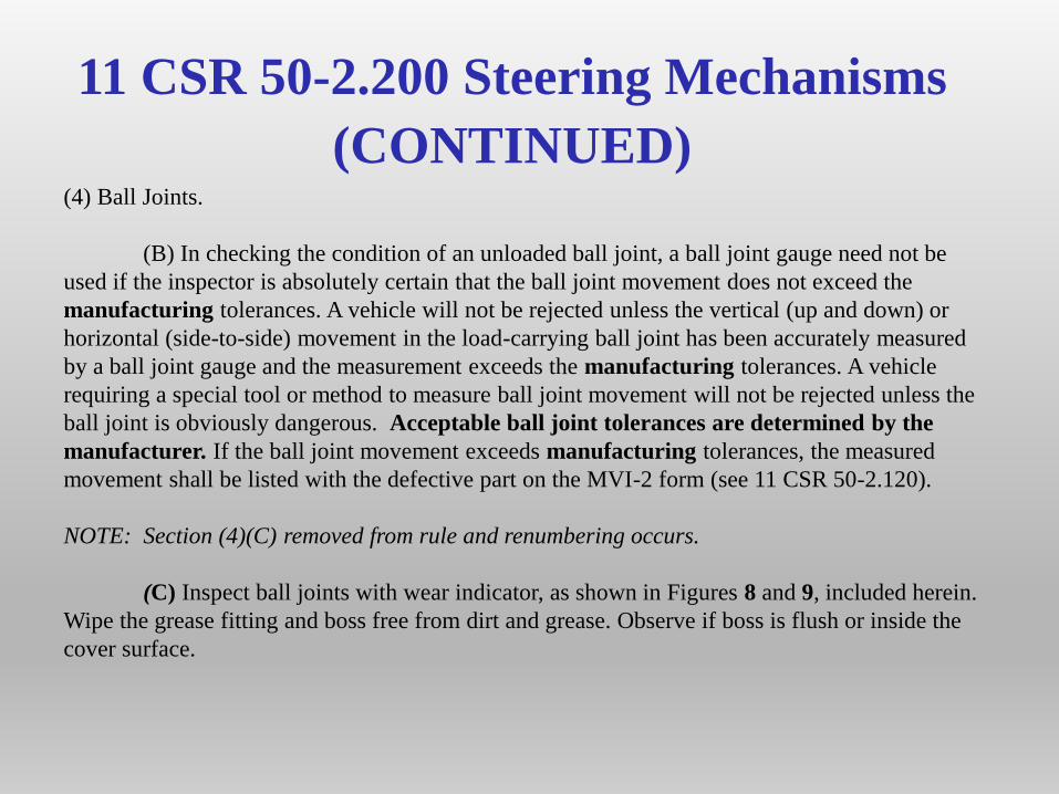
(CONTINUED)(4) Ball Joints.
(B) In checking the condition of an unloaded ball joint, a ball joint gauge need not be
used if the inspector is absolutely certain that the ball joint movement does not exceed the
manufacturing tolerances. A vehicle will not be rejected unless the vertical (up and down) or
horizontal (side-to-side) movement in the load-carrying ball joint has been accurately measured
by a ball joint gauge and the measurement exceeds the manufacturing tolerances. A vehicle
requiring a special tool or method to measure ball joint movement will not be rejected unless the
ball joint is obviously dangerous. Acceptable ball joint tolerances are determined by the
manufacturer. If the ball joint movement exceeds manufacturing tolerances, the measured
movement shall be listed with the defective part on the MVI-2 form (see 11 CSR 50-2.120).
NOTE: Section (4)(C) removed from rule and renumbering occurs.
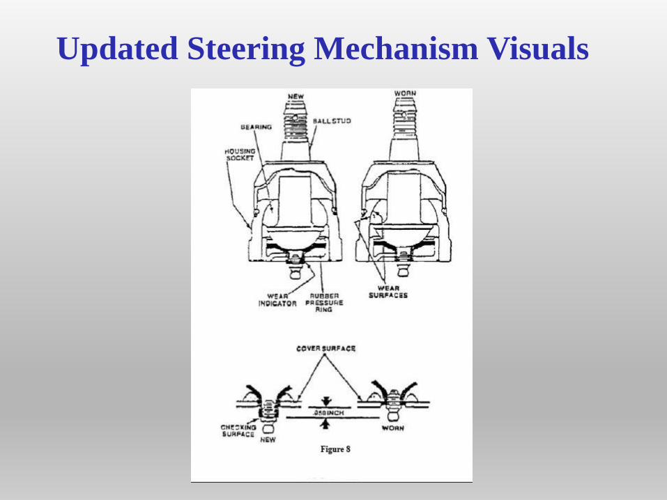
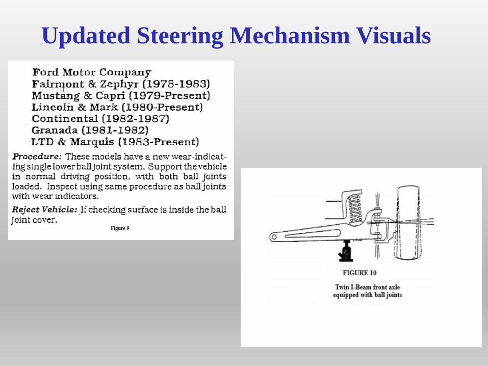
(C) Inspect ball joints with wear indicator, as shown in Figures 8 and 9, included herein.
Wipe the grease fitting and boss free from dirt and grease. Observe if boss is flush or inside the
cover surface.
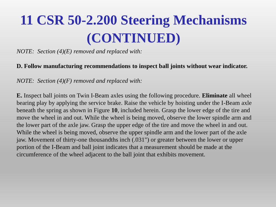
11 CSR 50-2.200 Steering Mechanisms
(CONTINUED)NOTE: Section (4)(E) removed and replaced with:
D. Follow manufacturing recommendations to inspect ball joints without wear indicator.
NOTE: Section (4)(F) removed and replaced with:
E. Inspect ball joints on Twin I-Beam axles using the following procedure. Eliminate all wheel
bearing play by applying the service brake. Raise the vehicle by hoisting under the I-Beam axle
beneath the spring as shown in Figure 10, included herein. Grasp the lower edge of the tire and
move the wheel in and out. While the wheel is being moved, observe the lower spindle arm and
the lower part of the axle jaw. Grasp the upper edge of the tire and move the wheel in and out.
While the wheel is being moved, observe the upper spindle arm and the lower part of the axle
jaw. Movement of thirty-one thousandths inch (.031") or greater between the lower or upper
portion of the I-Beam and ball joint indicates that a measurement should be made at the
circumference of the wheel adjacent to the ball joint that exhibits movement.
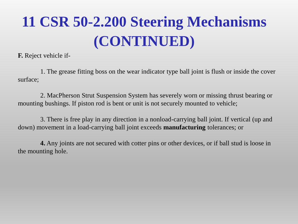
11 CSR 50-2.200 Steering Mechanisms
(CONTINUED)F. Reject vehicle if-
1. The grease fitting boss on the wear indicator type ball joint is flush or inside the cover
surface;
2. MacPherson Strut Suspension System has severely worn or missing thrust bearing or
mounting bushings. If piston rod is bent or unit is not securely mounted to vehicle;
3. There is free play in any direction in a nonload-carrying ball joint. If vertical (up and
down) movement in a load-carrying ball joint exceeds manufacturing tolerances; or
4. Any joints are not secured with cotter pins or other devices, or if ball stud is loose in
the mounting hole.
Updated Steering Mechanism Visuals
Updated Steering Mechanism Visuals
Updated Steering Mechanism Visuals
Updated Steering Mechanism Visuals
Updated Steering Mechanism Visuals
11 CSR 50-2.270 Glazing (Glass)
(3) Types of Damage or Defect.
(A) Outright breakage: Glass that is severely cracked, shattered, or broken to expose
sharp edges or missing pieces.
(B) Distortion: A manufacturing defect or other defect that causes a distorted view.
(C) Star break: Vented breaks with cracks radiating from point of impact.
(D) Bull’s-eye and half moon: Nonvented circular or half-circular chips not dislodged
from glass.
NOTE: (3)(E), defining “stone nicks/chips” has been removed from the manual.
11 CSR 50-2.270 Glazing (Glass)
(CONTINUED)
(5) Reject vehicle if –
(A) Required glazing is not present or improper glazing materials are used;
(B) Window at driver’s left cannot be readily opened to permit arm signals. (Do not
reject if the vehicle is equipped with properly operating turn signals and stoplight);
(C) After-market vision reducing material or other conditions that obscure the driver’s
vision is on the windshield;
(D) The windshield has any cracks exceeding three inches (3”) in length, within the
diver’s vision area;
(E) The windshield has any unrepaired star breaks, bull’s-eyes, or half moons within the
driver’s vision area;
11 CSR 50-2.270 Glazing (Glass)
(CONTINUED)
(F) The windshield has any of the following that are more than two inches (2”) in
diameter at any area outside the driver’s vision area: star breaks; bull’s-eyes; or half
moons;
(G) The windshield has any distortion; or
(H) Outright breakage, missing pieces, or any break exposing sharp edges is present at
any location.
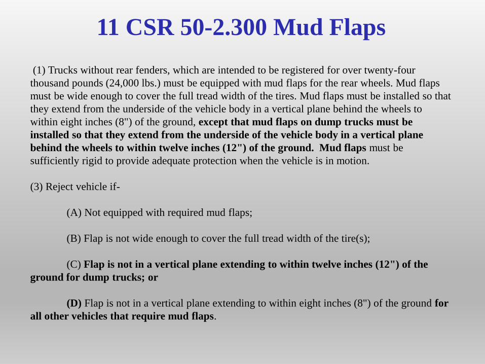
11 CSR 50-2.300 Mud Flaps
(1) Trucks without rear fenders, which are intended to be registered for over twenty-four
thousand pounds (24,000 lbs.) must be equipped with mud flaps for the rear wheels. Mud flaps
must be wide enough to cover the full tread width of the tires. Mud flaps must be installed so that
they extend from the underside of the vehicle body in a vertical plane behind the wheels to
within eight inches (8") of the ground, except that mud flaps on dump trucks must be
installed so that they extend from the underside of the vehicle body in a vertical plane
behind the wheels to within twelve inches (12") of the ground. Mud flaps must be
sufficiently rigid to provide adequate protection when the vehicle is in motion.
(3) Reject vehicle if-
(A) Not equipped with required mud flaps;
(B) Flap is not wide enough to cover the full tread width of the tire(s);
(C) Flap is not in a vertical plane extending to within twelve inches (12") of the
ground for dump trucks; or
(D) Flap is not in a vertical plane extending to within eight inches (8") of the ground for
all other vehicles that require mud flaps.
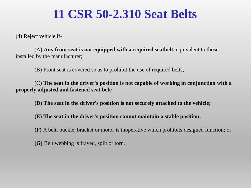
11 CSR 50-2.310 Seat Belts
(4) Reject vehicle if-
(A) Any front seat is not equipped with a required seatbelt, equivalent to those
installed by the manufacturer;
(B) Front seat is covered so as to prohibit the use of required belts;
(C) The seat in the driver's position is not capable of working in conjunction with a
properly adjusted and fastened seat belt;
(D) The seat in the driver's position is not securely attached to the vehicle;
(E) The seat in the driver's position cannot maintain a stable position;
(F) A belt, buckle, bracket or motor is inoperative which prohibits designed function; or
(G) Belt webbing is frayed, split or torn.
11 CSR 50-2.340
Off-Highway Use Vehicles (ATV-OHV)
11 CSR 50-2.340 is rescinded.
Neither ATV’s nor OHV’s are required to undergo a motor vehicle safety inspection.