Embed Size (px)
DESCRIPTION
Update on the MCTF Scenario(s). Y.Alexahin (FNAL). NFMCC meeting, Fermilab March 17-20, 2008. Parameters of Different MC options. Low Emit.High Emit.MCTF07 s (TeV)1.5 - PowerPoint PPT Presentation
Citation preview
NFMCC meeting, Fermilab March 17-20, 2008
Update on the MCTF Scenario(s)
Y.Alexahin
(FNAL)
MCTF Scenario - Y. Alexahin NFMCC meeting, FNAL, March 20, 2008
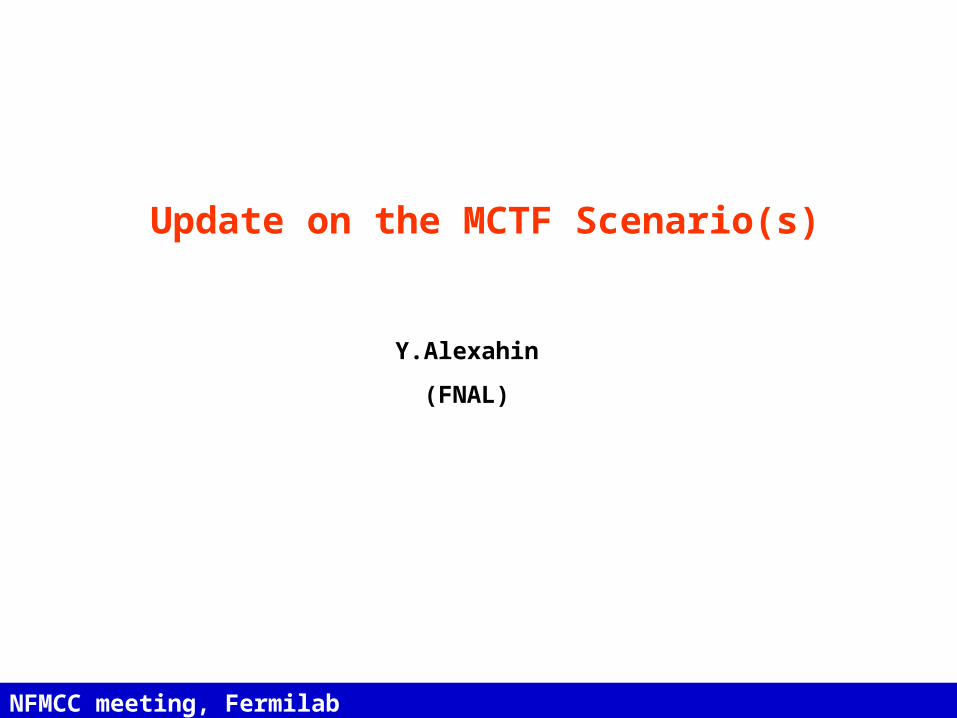
Parameters of Different MC options
Low Emit. High Emit. MCTF07s (TeV) 1.5Av. Luminosity (1034/cm2/s) * 2.7 1 1.33-2Av. Bending field (T) 10 6 6Mean radius (m) 361.4 500 500No. of IPs 4 2 2Proton Driver Rep Rate (Hz) 65 13 40-60Beam-beam parameter/IP 0.052 0.087 0.1* (cm) 0.5 1 1Bunch length (cm) 0.5 1 1No. bunches / beam 10 1 1No. muons/bunch (1011) 1 20 11.3Norm. Trans. Emit. (m) 2.1 25 12.3Energy spread (%) 1 0.1 0.2Norm. long. Emit. (m) 0.35 0.07 0.14Total RF voltage (GV) at 800MHz 407103c 0.21** 0.84**Muon survival N/N0 0.31 0.07 0.2+ in collision / proton 0.047 0.01 0.038 GeV proton beam power 3.62*** 3.2 1.9-2.8---------------------------------------------------------------------------*) Luminosity calculated taking account of the hour-glass factor but ignoring the dynamic beta effect.**) Momentum compaction in the present ring design c=1.510-4. Note that it would be better to assume f=1.3GHz to keep the RF voltage at a reasonable level (0.52GV for MCTF07 set)***) Assumes /p ratio of 0.15 after capture and precooling, and only decay losses afterwards. Positive and negative muons are assumed to be produced independently (from different protons).
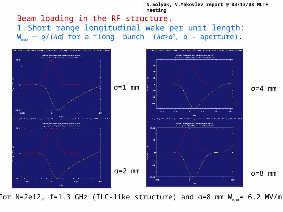
Beam loading in the RF structure.1. Short range longitudinal wake per unit length:Wmax ~ q/(λσ) for a “long” bunch (λσ>a2, a - aperture).
σ=1 mm
σ=2 mm
σ=4 mm
σ=8 mm
For N=2e12, f=1.3 GHz (ILC-like structure) and σ=8 mm Wmax= 6.2 MV/m!
N.Solyak, V.Yakovlev report @ 03/13/08 MCTF meeting
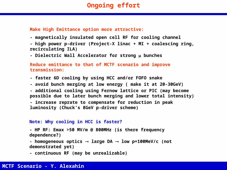
Ongoing effort
Make High Emittance option more attractive:
- magnetically insulated open cell RF for cooling channel - high power p-driver (Project-X linac + MI + coalescing ring, recirculating ILA)- Dielectric Wall Accelerator for strong bunches
Reduce emittance to that of MCTF scenario and improve transmission:
- faster 6D cooling by using HCC and/or FOFO snake- avoid bunch merging at low energy ( make it at 20-30GeV)- additional cooling using Fernow lattice or PIC (may become possible due to later bunch merging and lower total intensity)- increase reprate to compensate for reduction in peak luminosity (Chuck’s 8GeV p-driver scheme)
MCTF Scenario - Y. Alexahin NFMCC meeting, FNAL, March 20, 2008
Note: Why cooling in HCC is faster?
- HP RF: Emax >50 MV/m @ 800MHz (is there frequency dependence?)- homogeneous optics large DA low p=100MeV/c (not demonstrated yet)- continuous RF (may be unrealizable)
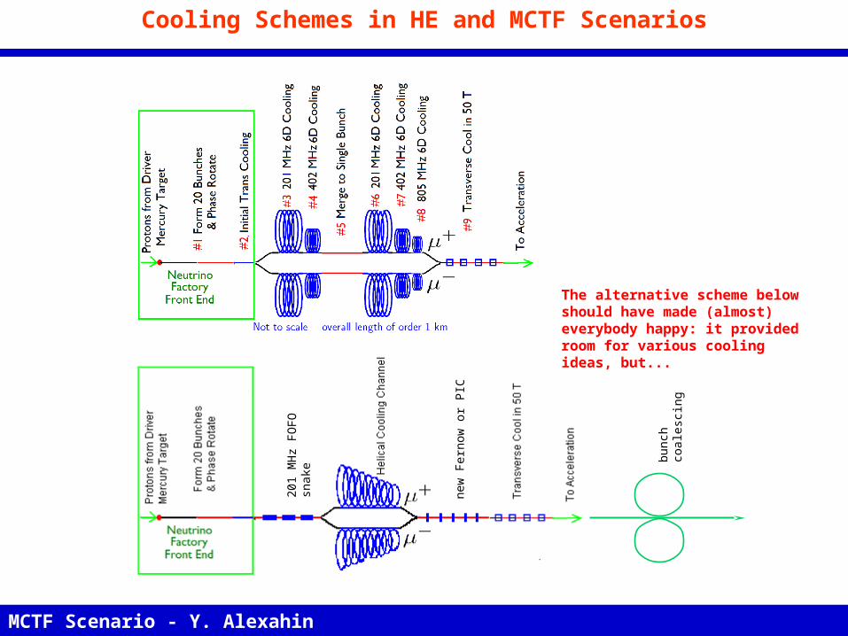
Cooling Schemes in HE and MCTF Scenarios
bunc
h co
ales
cing
MCTF Scenario - Y. Alexahin NFMCC meeting, FNAL, March 20, 2008
201
MH
z FO
F O s
nake
new
Fe r
now
or P
IC
The alternative scheme below should have made (almost) everybody happy: it provided room for various cooling ideas, but...
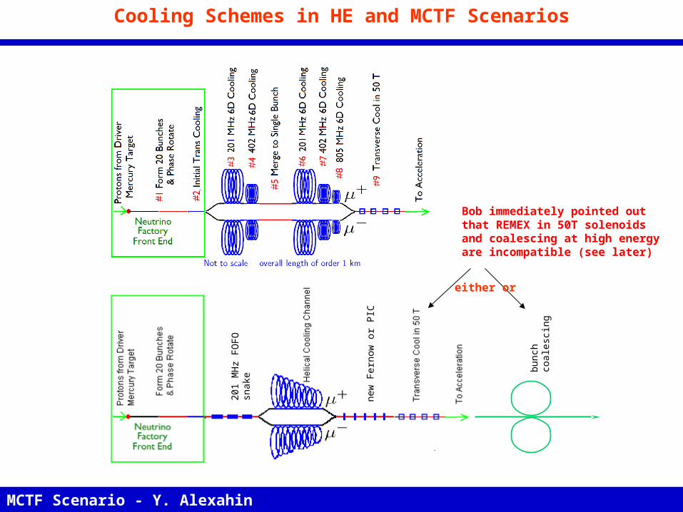
Cooling Schemes in HE and MCTF Scenarios
bunc
h co
ales
cing
MCTF Scenario - Y. Alexahin NFMCC meeting, FNAL, March 20, 2008
201
MH
z FO
F O s
nake
new
Fe r
now
or P
IC
Bob immediately pointed out that REMEX in 50T solenoids and coalescing at high energy are incompatible (see later)
either or
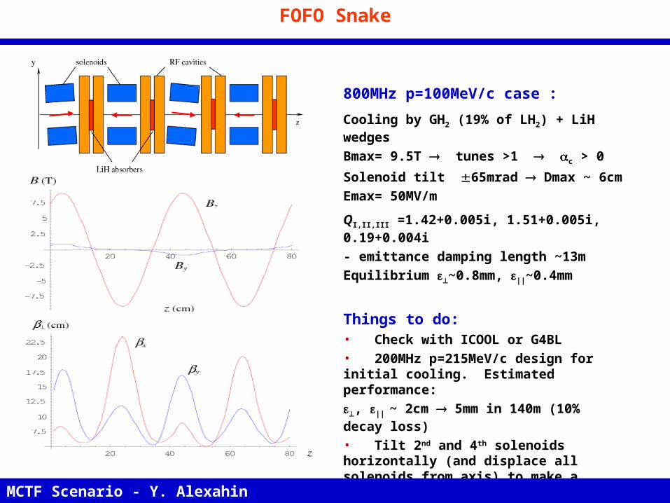
FOFO Snake
800MHz p=100MeV/c case :Cooling by GH2 (19% of LH2) + LiH wedgesBmax= 9.5T tunes >1 c > 0Solenoid tilt 65mrad Dmax ~ 6cmEmax= 50MV/m
QI,II,III =1.42+0.005i, 1.51+0.005i, 0.19+0.004i- emittance damping length ~13mEquilibrium ~0.8mm, ||~0.4mm
Things to do:• Check with ICOOL or G4BL • 200MHz p=215MeV/c design for initial cooling. Estimated performance:, || ~ 2cm 5mm in 140m (10% decay loss)• Tilt 2nd and 4th solenoids horizontally (and displace all solenoids from axis) to make a helix. Hopefully c will become large enough to discard LiH wedges smaller emittances
MCTF Scenario - Y. Alexahin NFMCC meeting, FNAL, March 20, 2008
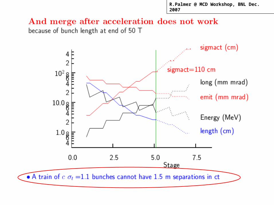
R.Palmer @ 12/14/06 MCTF meeting
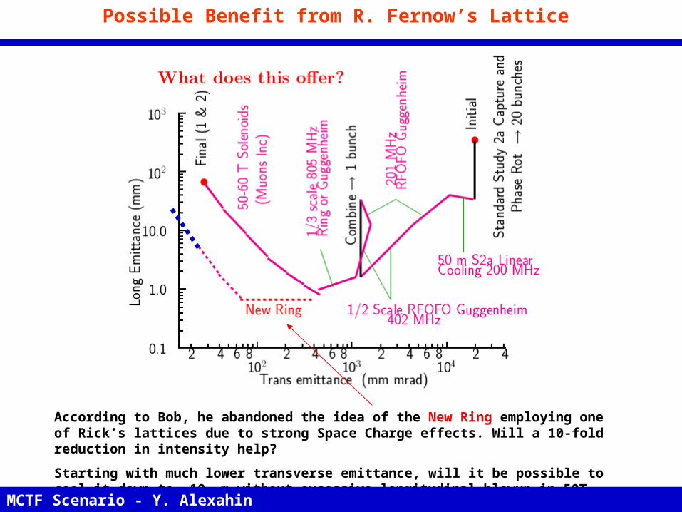
Possible Benefit from R. Fernow’s Lattice
According to Bob, he abandoned the idea of the New Ring employing one of Rick’s lattices due to strong Space Charge effects. Will a 10-fold reduction in intensity help?
Starting with much lower transverse emittance, will it be possible to cool it down to ~10 m without excessive longitudinal blowup in 50T solenoids?
MCTF Scenario - Y. Alexahin NFMCC meeting, FNAL, March 20, 2008
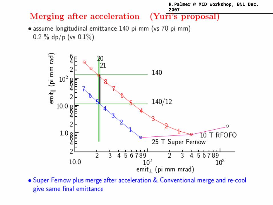
R.Palmer @ MCD Workshop, BNL Dec. 2007
R.Palmer @ MCD Workshop, BNL Dec. 2007
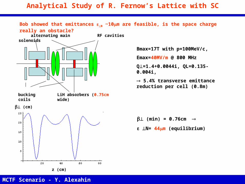
Analytical Study of R. Fernow’s Lattice with SC
Bob showed that emittances N ~10m are feasible, is the space charge really an obstacle?
z (cm)
MCTF Scenario - Y. Alexahin NFMCC meeting, FNAL, March 20, 2008
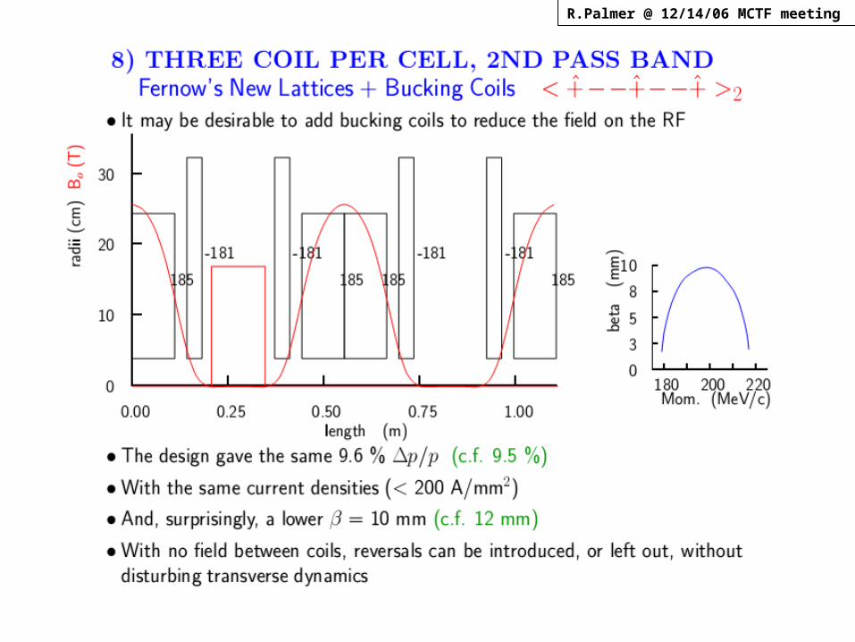
RF cavities
bucking coils LiH absorbers (0.75cm wide)
alternating main solenoids
(cm)
Bmax=17T with p=100MeV/c,
Emax=40MV/m @ 800 MHz
Q=1.4+0.0044i, QL=0.135- 0.004i,
5.4% transverse emittance reduction per cell (0.8m)
(min) = 0.76cm
N= 44m (equilibrium)
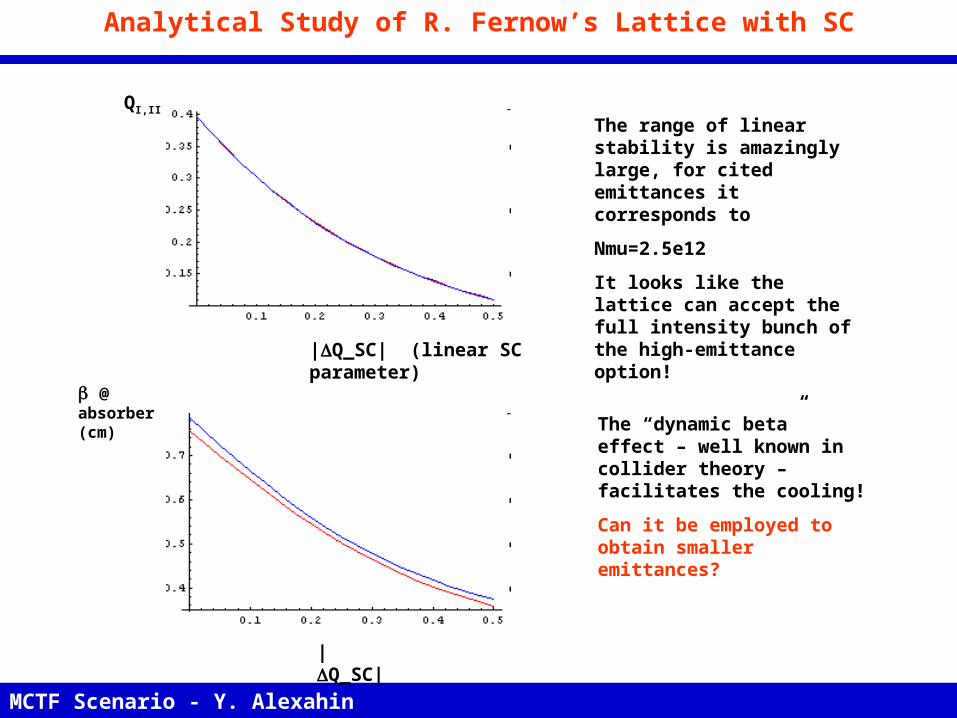
Analytical Study of R. Fernow’s Lattice with SC
MCTF Scenario - Y. Alexahin NFMCC meeting, FNAL, March 20, 2008
|Q_SC|
@ absorber (cm)
QI,II
|Q_SC| (linear SC parameter)
The range of linear stability is amazingly large, for cited emittances it corresponds to
Nmu=2.5e12
It looks like the lattice can accept the full intensity bunch of the high-emittance option!
The “dynamic beta” effect – well known in collider theory – facilitates the cooling!
Can it be employed to obtain smaller emittances?
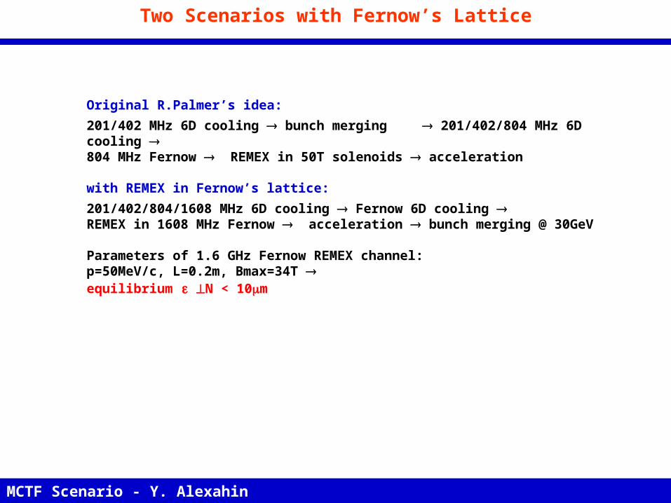
Two Scenarios with Fernow’s Lattice
Original R.Palmer’s idea:201/402 MHz 6D cooling bunch merging 201/402/804 MHz 6D cooling 804 MHz Fernow REMEX in 50T solenoids acceleration
with REMEX in Fernow’s lattice:201/402/804/1608 MHz 6D cooling Fernow 6D cooling REMEX in 1608 MHz Fernow acceleration bunch merging @ 30GeV
Parameters of 1.6 GHz Fernow REMEX channel:p=50MeV/c, L=0.2m, Bmax=34T equilibrium N < 10m
MCTF Scenario - Y. Alexahin NFMCC meeting, FNAL, March 20, 2008