Embed Size (px)
Citation preview
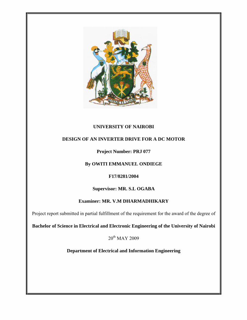
UNIVERSITY OF NAIROBI
DESIGN OF AN INVERTER DRIVE FOR A DC MOTOR
Project Number: PRJ 077
By OWITI EMMANUEL ONDIEGE
F17/8281/2004
Supervisor: MR. S.L OGABA
Examiner: MR. V.M DHARMADHIKARY
Project report submitted in partial fulfillment of the requirement for the award of the degree of
Bachelor of Science in Electrical and Electronic Engineering of the University of Nairobi
20th MAY 2009
Department of Electrical and Information Engineering
ii
ABSTRACT
Today in industries the world over, a large part of electric energy consumption is by electric
motor drives. This brings out the need for the design of electric motor drive control systems with
the main aims being to increase the efficiency, economize power consumption and achieve a
fully controllable variable speed drive system.
The project entailed the study of the conventional methods of dc motor control hence noting their
inefficiencies, then the design and implementation of an inverter drive that can be used to control
the speed of a dc motor.
iii
Table of Contents ABSTRACT .................................................................................................................................... ii
ACKNOWLEDEGMENT ............................................................................................................... v
CHAPTER 1: INTRODUCTION .................................................................................................. 1
1.1 Advantages of Electronic Control ......................................................................................... 1
1.2 Objectives ............................................................................................................................. 2
CHAPTER 2: ELECTRIC MOTORS ........................................................................................... 4
2.1 How a motor works ............................................................................................................... 4
2.2 Direct Current (DC) motors .................................................................................................. 6
2.2.1 Separately excited DC motor ......................................................................................... 8
2.2.2 Self excited DC motor: series motor .............................................................................. 8
2.2.3 Self excited DC motor: shunt motor .............................................................................. 9
2.2.4 DC Compound Motor .................................................................................................. 10
2.3 AC Motors .......................................................................................................................... 11
2.3.1 Synchronous motor ...................................................................................................... 12
2.3.2 Induction motor ............................................................................................................ 13
CHAPTER 3: SPEED CONTROL OF DC MOTORS ............................................................... 15
3.1 SPEED CONTROL OF DC SHUNT MOTORS. ............................................................... 16
3.1.1 Flux control method. .................................................................................................... 16
3.1.2 Armature control method. ............................................................................................ 17
3.1.3 Voltage control method................................................................................................ 18
3.2 SPEED CONTROL OF DC SERIES MOTORS ................................................................ 19
3.2.1 Flux control method. .................................................................................................... 20
3.2.2 Armature resistance control. ........................................................................................ 21
3.2.3 Series-Parallel control method. .................................................................................... 22
iv
CHAPTER 4: FINAL DESIGN .................................................................................................. 24
4.1 THEORY OF THE CIRCUIT ............................................................................................ 24
4.2 COMPONENT DESIGN .................................................................................................... 27
4.2.1 Input rectifier ............................................................................................................... 27
4.2.2 Control circuit .............................................................................................................. 28
4.2.3 DC – AC Converter ..................................................................................................... 30
4.2.4 Rectifier and filter ........................................................................................................ 32
4.3 RESULTS AND ANALYSIS ............................................................................................. 34
CHAPTER 5: CONCLUSION ..................................................................................................... 36
5.1 RECOMMENDATIONS AND FURTHER WORK .......................................................... 36
REFERENCES ............................................................................................................................ 37
APPENDIX : DATA SHEETS .................................................................................................... 38

v
ACKNOWLEDEGMENT
I would like to thank Mr. Ogaba for spending his valuable time in supervising my project and
assisting me in all ways possible in order for me to meet the project requirements, and to Mr.
Dharmadhikary for taking his time to examine my project.
I would also like to thank the technical staff; Mr. Muraba and Mr. Wanyoike for their technical
assistance.
Lastly I would like to sincerely thank my classmates who, not just throughout the project but
throughout the five years, have provided immense support and advice.
1
CHAPTER 1: INTRODUCTION
It is essential to vary the speed of electric drives in different field of applications. Normally in all
process industries, it is desired that the system be set at slow speed in the beginning and then
gradually increased to meet the maximum production rate. An example of a newspaper printing
press may be taken here. Various pages of the newspaper are printed by different stands and then
combined, cut and folded. The entire process is first set at a slow pace so that, the wastage of
newsprint is minimum. Once the process is set, the speed of the entire system is increased to
quicken the production. There can be many processes where variable speed drives are required.
One of the major achievements of power electronic technology in the field of control is the
control of dc motor drives. Because of their tremendous control capabilities, solid state motor
control schemes have almost replaced the conventional electrical control methods.
Because of their manifold advantages such as compactness, fast response, higher efficiency,
more control capabilities, more reliability and less cost, power electronic controlled schemes
have totally dominated the field of control of dc motors.
There are several advantages of electronic control systems as compared to the conventional
methods. They are as follows.
1.1 Advantages of Electronic Control
1. Electronic control systems are very compact and small in size, and thus require
comparatively less space.
2. They require less power.
3. They are fast in response.
4. They are much more accurate and efficient than the conventional methods.
5. System reliability is much more than the usual conventional methods.
6. An electronic control system is economical as compared to other systems as it involves
minimum maintenance cost.
7. An electronic system is highly protective and the devices under control are much safe as
compared to other systems.
2
1.2 Objectives
The objectives of the project were to:
• Do a study of dc motor control by conventional methods.
• Design an inverter drive to control a dc motor.
• Test the designed inverter drive.
A study of the control of dc motors was carried out and was dealt with in chapter 3 of the project
report. The three main methods that were discussed were:
a. Varying the flux per pole. This is known as flux control method.
b. Varying the resistance in the armature circuit. This is known as armature control
method.
c. Varying the applied voltage. This is known as voltage control.
It is seen that these conventional methods, though they formed the background by which the
power electronic control devices are used in control, they are found to be wasteful in terms of the
amount of power consumed.
3
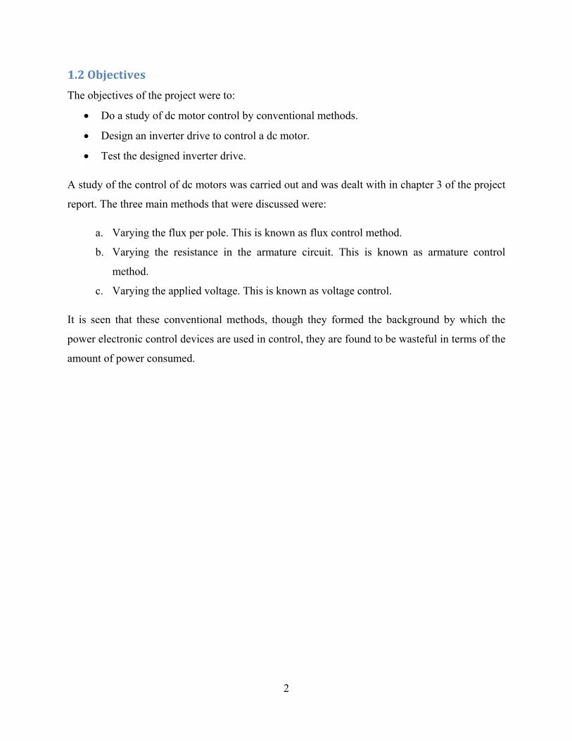
Figure 1.1 Block diagram of the inverter drive
In chapter 4, the final design schematic is shown (figure 4.1). Here an in depth explanation of the
circuit is given with the circuit being segmented to give the reader better understanding. The
circuit could also be represented as shown in the block diagram in figure 1.1.
Control Unit - Rectifier - 555 timer - Voltage Comparator - Optical Coupler
Semiconductor Switching Device (MOSFETs)
Dc output Dc motor
AC MAINS
4
CHAPTER 2: ELECTRIC MOTORS
An electric motor is an electromechanical device that converts electrical energy to mechanical
energy. This mechanical energy is used, for example, in rotating a pump impeller, fan or blower,
driving a compressor, lifting materials etc. Electric motors are used at home (mixer, drill, fan)
and in industry. Electric motors are sometimes called the “work horses” of industry because it is
estimated that motors use about 70% of the total electrical load in industry.
2.1 How a motor works
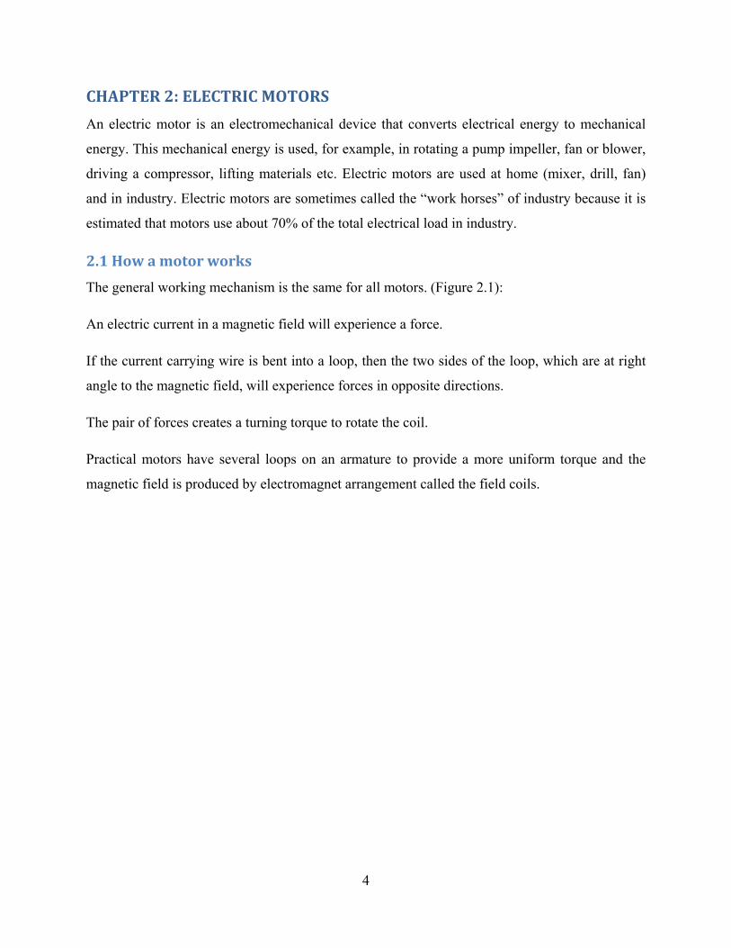
The general working mechanism is the same for all motors. (Figure 2.1):
An electric current in a magnetic field will experience a force.
If the current carrying wire is bent into a loop, then the two sides of the loop, which are at right
angle to the magnetic field, will experience forces in opposite directions.
The pair of forces creates a turning torque to rotate the coil.
Practical motors have several loops on an armature to provide a more uniform torque and the
magnetic field is produced by electromagnet arrangement called the field coils.
5
Figure 2.1 Basic Principle of how Electric Motors Work
In understanding a motor it is important to understand what a motor load means. Load refers to
the torque output and corresponding speed required. Loads can generally be categorized into
three groups:
• Constant torque loads are those for which the output power requirement may vary with
the speed of operation but the torque does not vary. Conveyors, rotary kilns, and
constant-displacement pumps are typical examples of constant torque loads.
• Variable torque loads are those for which the torque required varies with the speed of
operation. Centrifugal pumps and fans are typical examples of variable torque loads
(torque varies as the square of the speed).
• Constant power loads are those for which the torque requirements typically change
inversely with speed. Machine tools are a typical example of a constant power load.
Components of electric motors vary between different types of motors and are therefore
described for each motor separately.
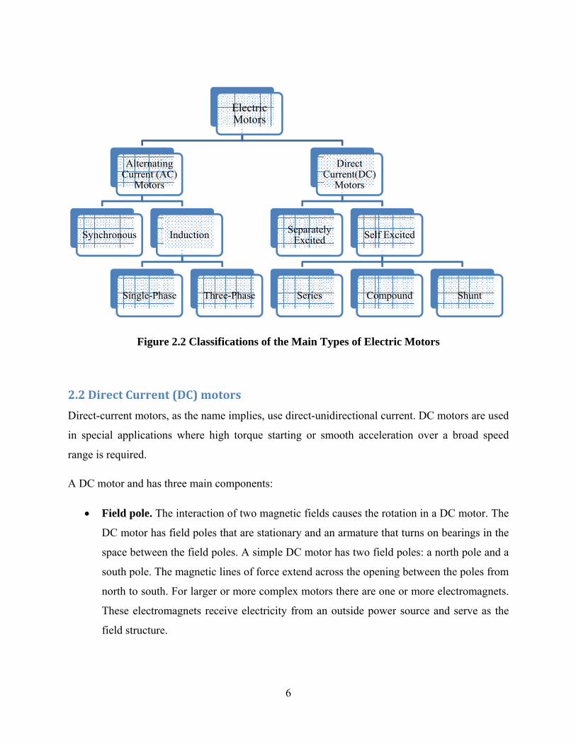
2.2 Dire
Direct-cu
in specia
range is r
A DC mo
• F
D
sp
so
n
T
fi
Synch
Figur
ect Curren
urrent motor
al applicatio
required.
otor and has
Field pole. T
DC motor ha
pace betwee
outh pole. Th
orth to south
These electro
ield structure
AlternatiCurrent (A
Motors
hronous
Single-Ph
re 2.2 Classi
nt (DC) mo
rs, as the nam
ons where hi
three main c
The interactio
s field poles
n the field p
he magnetic
h. For larger
omagnets rec
e.
ing AC) s
Induction
hase Thr
ifications of
otors
me implies, u
igh torque s
components
on of two ma
s that are sta
poles. A simp
c lines of for
r or more co
ceive electri
Electric Motors
ree-Phase
6
f the Main T
use direct-un
starting or s
:
agnetic field
ationary and
ple DC moto
ce extend ac
mplex moto
icity from an
SeparateExcited
Series
Types of Ele
nidirectional
smooth acce
ds causes the
an armature
or has two fi
cross the ope
ors there are
n outside po
Direct Current(DC)
Motors
ly d Sel
Co
ectric Motor
l current. DC
eleration ove
e rotation in
e that turns o
field poles: a
ening betwee
one or more
ower source
f Excited
ompound
rs
C motors are
er a broad s
a DC motor
on bearings i
a north pole a
en the poles
e electromag
and serve a
Shunt
used
speed
r. The
in the
and a
from
gnets.
as the
7
• Armature. When current goes through the armature, it becomes an electromagnet. The
armature, cylindrical in shape, is linked to a drive shaft in order to drive the load. For the
case of a small DC motor, the armature rotates in the magnetic field established by the
poles, until the north and south poles of the magnets change location with respect to the
armature. Once this happens, the current is reversed to switch the south and north poles
of the armature.
• Commutator. Its purpose is to overturn the direction of the electric current in the
armature. The commutator also aids in the transmission of current between the armature
and the power source.
The main advantage of DC motors is speed control, which does not affect the quality of power
supply. It can be controlled by adjusting:
The armature voltage – increasing the armature voltage will increase the speed
The field current – reducing the field current will increase the speed.
DC motors are available in a wide range of sizes, but their use is generally restricted to a few low
speed, low-to-medium power applications like machine tools and rolling mills because of
problems with mechanical commutation at large sizes. Also, they are restricted for use only in
clean, non-hazardous areas because of the risk of sparking at the brushes. DC motors are also
expensive relative to AC motors.
The relationship between speed, field flux and armature voltage is shown in the following
equation:
Back electromagnetic force: E = KvΦN (2.1)
Torque: T = KtΦIa (2.2)
Where:
E = electromagnetic force developed at armature terminal (volt)
Φ = field flux which is directly proportional to field current
N = speed in RPM (revolutions per minute)
8
T = electromagnetic torque
Ia = armature current
Kv = voltage constant
Kt = torque constant
2.2.1 Separately excited DC motor
In many traction applications where both armature voltage and stator current are needed to
control the speed and torque of the motor from “no load” to “full load”, the separately excited
DC motor is used for it’s high torque capability at low speed achieved by separately generating a
high stator field current and enough armature voltage to produce the required rotor torque
current. As torque decreases and speed increases, the stator field current requirement decreases
and the armature voltage increases. Without any load the speed of the separately excited motor is
limited by the armature voltage and stator field current.
2.2.2 Self excited DC motor: series motor
In the series motor, the field windings, consisting of a relatively few turns of heavy wire, are
connected in series with the armature winding. The same current flows through the field winding
and the armature winding. Any increase in current, therefore, strengthens the magnetism of both
the field and the armature.
Because of the low resistance in the winding, the series motor is able to draw a large current
during starting. This high starting current is what produces a high starting torque, which is the
series motor’s principal advantage.
The speed of a series motor is dependent upon the load. Any change in load is accompanied by a
substantial change in speed. A series motor will run at high speed when it has light load and at
low speed with a heavy load. If the load is removed, the motor may operate at such high speed
that the armature will fly apart. Series motors are suited for applications requiring a high starting
torque, such as cranes and hoists.
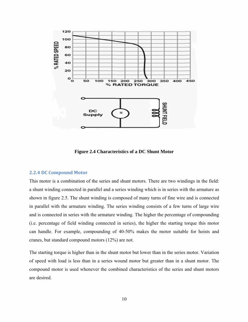
2.2.3 Se
In a shu
winding
and arma
connecte
The fiel
torque o
develope
The spee
assumes
when con
lf excited D
unt motor, th
(A) as show
ature curren
ed directly ac
ld current do
f the shunt
ed at starting
ed of the shu
a speed slig
nstant speed
Figur
DC motor: s
he field win
wn in figure
nt. The resis
cross the pow
oes not vary
motor will
g is less than
unt motor var
ghtly higher t
is desired an
re 2.3 Chara
shunt moto
nding (shun
2.4. The to
stance in the
wer supply, t
y with moto
vary only
that develop
ries very litt
than the load
nd when hig
9
acteristics o
or
nt field) is c
otal line curr
e field wind
the current th
or speed, as
with the cu
ped by a seri
le with chan
ded speed. T
gh starting to
of a DC Seri
connected in
rent is theref
ding is high
hrough the f
s in the seri
urrent throug
ies motor of
nges in load.
This motor is
orque is not r
ies Motor
n parallel w
fore the sum
h. Since the
field is const
es motor an
gh the arma
f equal size.
When all lo
s particularly
required.
with the arm
m of field cu
field windi
tant.
nd, therefore
ature. The to
oad is remov
y suitable fo
mature
urrent
ing is
e, the
orque
ved, it
or use
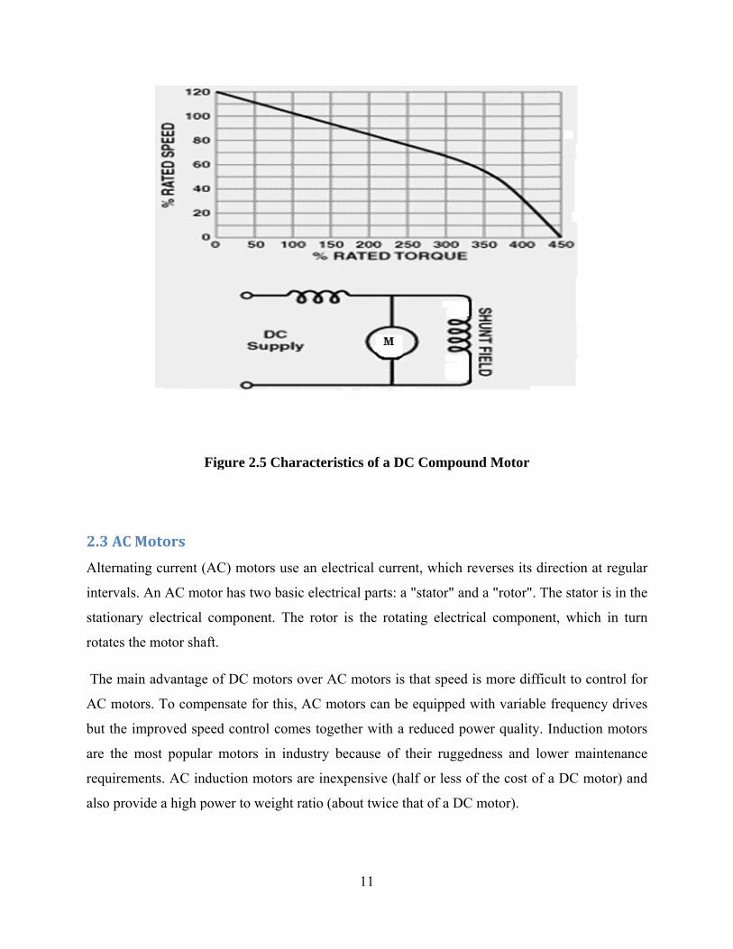
2.2.4 DC
This mot
a shunt w
shown in
in paralle
and is co
(i.e. perc
can hand
cranes, b
The start
of speed
compoun
are desire
C Compoun
tor is a comb
winding conn
n figure 2.5.
el with the a
onnected in s
centage of fi
dle. For exa
ut standard c
ting torque is
with load i
nd motor is
ed.
Figure 2.
nd Motor
bination of t
nected in par
The shunt w
armature win
series with th
ield winding
ample, comp
compound m
s higher than
s less than i
used whene
.4 Characte
the series an
rallel and a s
winding is co
nding. The
he armature
g connected
pounding of
motors (12%
n in the shun
in a series w
ver the com
10
ristics of a D
nd shunt mot
series windin
omposed of m
series windi
winding. Th
in series), t
f 40-50% m
%) are not.
nt motor but
wound motor
mbined chara
DC Shunt M
tors. There a
ng which is i
many turns o
ing consists
he higher the
the higher th
makes the m
lower than i
r but greater
acteristics of
Motor
are two wind
in series wit
of fine wire
of a few tu
e percentage
he starting t
motor suitabl
in the series
r than in a s
f the series a
dings in the
th the armatu
and is conn
urns of large
of compoun
torque this m
le for hoists
motor. Vari
shunt motor
and shunt m
field:
ure as
ected
wire
nding
motor
s and
iation
. The
motors
2.3 AC M
Alternati
intervals.
stationary
rotates th
The mai
AC moto
but the im
are the m
requirem
also prov
F
Motors
ing current (
. An AC mo
y electrical
he motor sha
in advantage
ors. To comp
mproved spe
most popula
ments. AC ind
vide a high p
Figure 2.5 C
(AC) motors
otor has two
component.
aft.
e of DC mot
pensate for t
eed control
ar motors in
duction mot
power to wei
Characteris
s use an elec
basic electri
. The rotor
tors over AC
this, AC mo
comes toget
n industry b
tors are inex
ight ratio (ab
11
tics of a DC
ctrical curren
ical parts: a "
is the rotati
C motors is t
otors can be
ther with a r
ecause of th
xpensive (hal
bout twice th
C Compound
nt, which rev
"stator" and
ing electrica
that speed is
equipped w
reduced pow
heir ruggedn
lf or less of
hat of a DC m
d Motor
verses its dir
a "rotor". T
al componen
s more diffic
ith variable
wer quality. I
ness and low
the cost of
motor).
rection at re
he stator is i
nt, which in
cult to contro
frequency d
Induction m
wer mainten
a DC motor
egular
in the
n turn
ol for
drives
motors
nance
r) and
12
2.3.1 Synchronous motor
A synchronous motor is an AC motor, which runs at constant speed fixed by frequency of the
system. It requires direct current (DC) for excitation and has low starting torque, and
synchronous motors are therefore suited for applications that start with a low load, such as air
compressors, frequency changes and motor generators. Synchronous motors are able to improve
the power factor of a system, which is why they are often used in systems that use a lot of
electricity.
The main components of a synchronous motor are:
Rotor. The main difference between the synchronous motor and the induction motor is that the
rotor of the synchronous motor travels at the same speed as the rotating magnetic field. This is
possible because the magnetic field of the rotor is no longer induced. The rotor either has
permanent magnets or DC-excited currents, which are forced to lock into a certain position when
confronted with another magnetic field.
Stator. The stator produces a rotating magnetic field that is proportional to the frequency
supplied.
This motor rotates at a synchronous speed (Ns), which is given by equation (2.3):
Ns = 120 f / P (2.3) Where:
f = frequency of the supply
P= number of poles
13
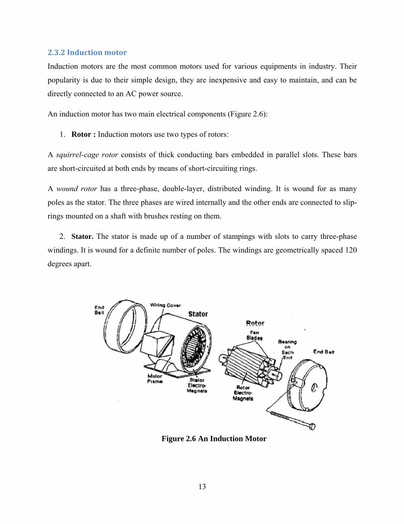
2.3.2 Induction motor
Induction motors are the most common motors used for various equipments in industry. Their
popularity is due to their simple design, they are inexpensive and easy to maintain, and can be
directly connected to an AC power source.
An induction motor has two main electrical components (Figure 2.6):
1. Rotor : Induction motors use two types of rotors:
A squirrel-cage rotor consists of thick conducting bars embedded in parallel slots. These bars
are short-circuited at both ends by means of short-circuiting rings.
A wound rotor has a three-phase, double-layer, distributed winding. It is wound for as many
poles as the stator. The three phases are wired internally and the other ends are connected to slip-
rings mounted on a shaft with brushes resting on them.
2. Stator. The stator is made up of a number of stampings with slots to carry three-phase
windings. It is wound for a definite number of poles. The windings are geometrically spaced 120
degrees apart.
Figure 2.6 An Induction Motor
14
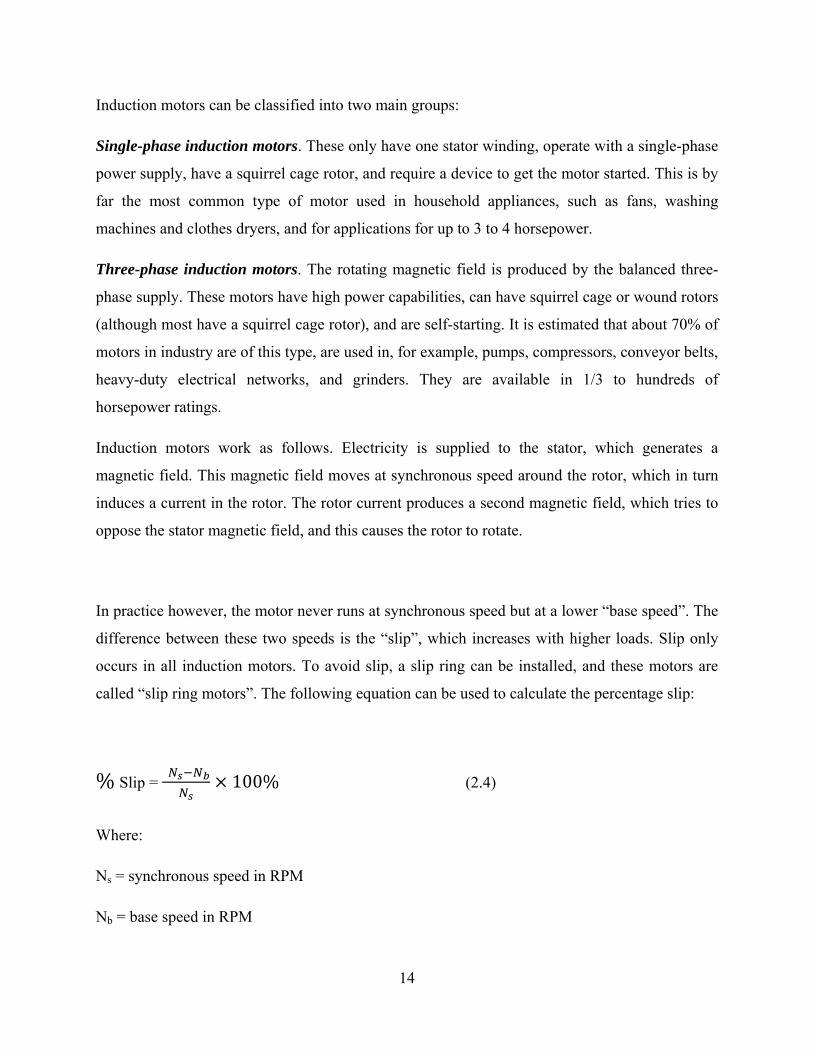
Induction motors can be classified into two main groups:
Single-phase induction motors. These only have one stator winding, operate with a single-phase
power supply, have a squirrel cage rotor, and require a device to get the motor started. This is by
far the most common type of motor used in household appliances, such as fans, washing
machines and clothes dryers, and for applications for up to 3 to 4 horsepower.
Three-phase induction motors. The rotating magnetic field is produced by the balanced three-
phase supply. These motors have high power capabilities, can have squirrel cage or wound rotors
(although most have a squirrel cage rotor), and are self-starting. It is estimated that about 70% of
motors in industry are of this type, are used in, for example, pumps, compressors, conveyor belts,
heavy-duty electrical networks, and grinders. They are available in 1/3 to hundreds of
horsepower ratings.
Induction motors work as follows. Electricity is supplied to the stator, which generates a
magnetic field. This magnetic field moves at synchronous speed around the rotor, which in turn
induces a current in the rotor. The rotor current produces a second magnetic field, which tries to
oppose the stator magnetic field, and this causes the rotor to rotate.
In practice however, the motor never runs at synchronous speed but at a lower “base speed”. The
difference between these two speeds is the “slip”, which increases with higher loads. Slip only
occurs in all induction motors. To avoid slip, a slip ring can be installed, and these motors are
called “slip ring motors”. The following equation can be used to calculate the percentage slip:
% Slip = 100% (2.4)
Where:
Ns = synchronous speed in RPM
Nb = base speed in RPM
15
CHAPTER 3: SPEED CONTROL OF DC MOTORS
Although a far greater percentage of electric motors in service are ac motors, the dc motor is of
considerable industrial importance. The principal advantage of a dc motor is that its speed can be
changed over a wide range by a variety of simple methods. Such fine speed control is not
possible with ac motors.
In fact fine speed control is one of the reasons for the strong competitive position of dc motors in
modern industrial applications. In this chapter the various methods of speed control of dc motors
are discussed.
The speed (N) of a dc motor is given by:
N α
N = rpm (3.1)
Where R = Ra shunt motor
R = Ra + Rse series motor
Ia – armature current
Eb – back emf
From equation (3.1), it is clear that there are three main methods of controlling the speed of a dc
motor, namely:
i. By varying the flux per pole ( . This is known as flux control method.
ii. By varying the resistance in the armature (Ra) circuit. This is known as armature control
method.
iii. By varying the applied voltage, V. This is known as voltage control method.
16
3.1 SPEED CONTROL OF DC SHUNT MOTORS.
The speed of a shunt motor can be changed by:
i. Flux control method.
ii. Armature control method.
iii. Voltage control method.
The first method i.e. flux control, is frequently used because it is simple and inexpensive.
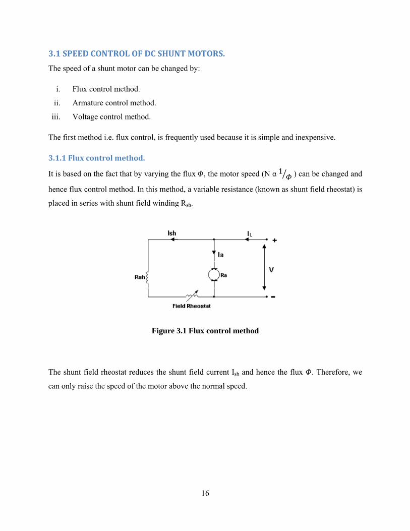
3.1.1 Flux control method.
It is based on the fact that by varying the flux , the motor speed (N α 1 ) can be changed and
hence flux control method. In this method, a variable resistance (known as shunt field rheostat) is
placed in series with shunt field winding Rsh.
Figure 3.1 Flux control method
The shunt field rheostat reduces the shunt field current Ish and hence the flux . Therefore, we
can only raise the speed of the motor above the normal speed.
17
Advantages
i. This is an easy and convenient method.
ii. It is an inexpensive method since very little power is wasted in the shunt field resistor due
to relatively small value of shunt field current Ish.
Disadvantages
i. Only speeds higher than normal can be obtained since the total field circuit resistance
cannot be reduced below the shunt field winding Rsh.
ii. There is a limit to the maximum speed obtainable by this method. It is because if the flux
is too much weakened, the commutation becomes poorer.
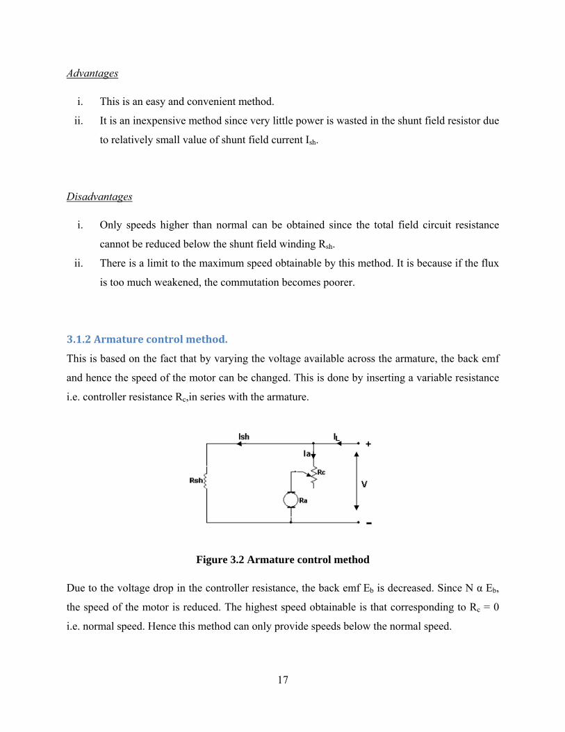
3.1.2 Armature control method.
This is based on the fact that by varying the voltage available across the armature, the back emf
and hence the speed of the motor can be changed. This is done by inserting a variable resistance
i.e. controller resistance Rc,in series with the armature.
Figure 3.2 Armature control method
Due to the voltage drop in the controller resistance, the back emf Eb is decreased. Since N α Eb, the speed of the motor is reduced. The highest speed obtainable is that corresponding to Rc = 0
i.e. normal speed. Hence this method can only provide speeds below the normal speed.
18
Disadvantages.
i. A large amount of power is wasted in the controller resistance since it carries full
armature current Ia.
ii. The speed varies with load since the speed depends upon the voltage drop in the
controller resistance and hence on the armature current demanded by the load.
iii. The output and efficiency of the motor are reduced.
iv. This method results in poor speed regulation.
3.1.3 Voltage control method.
In this method, the voltage source supplying the field current is different from that which
supplies the armature. This method avoids the disadvantages of poor speed regulation and low
efficiency as in armature control method. However, it is quite expensive. Therefore this method
of speed control is employed for large size motors where efficiency is of great importance.
Multiple voltage control.
In this method, the shunt field of the motor is connected permanently across a fixed voltage
source. The armature can be connected across several different voltages through a suitable
switchgear. In this way, voltage applied across the armature can be changed. The speed will be
approximately proportional to the voltage applied across the armature.
Ward-Leonard System.
In this method, the adjustable voltage for the armature is obtained from an adjustable voltage
generator while the field circuit is supplied from a separate source. The armature of the shunt
motor (whose speed is to be controlled) is connected directly to a dc generator driven by a
constant speed ac motor. The field of the shunt motor is supplied from a constant-voltage exciter.
The field of the generator is also supplied from the exciter. The voltage of the generator can be
varied by means of its field regulator.
19
By reversing the field current of the generator by a controller, the voltage applied to the motor is
reversed. Sometimes a field regulator is included in the field circuit of the shunt motor for
additional speed adjustment.
With this method, the motor may be operated at any speed up to its maximum speed.
Advantages.
i. The speed of the motor can be adjusted through a wide range without resistance losses
which results in high efficiency.
ii. The motor can be brought to a standstill quickly, simply by rapidly reducing the voltage
of generator. When the generator voltage is reduced below the back emf of the motor,
this back emf sends current through the generator armature, establishing dynamic
braking. While this takes place, the generator operates as a motor driving the ac motor
which returns power to the line.
iii. This method is used for the speed control of large motors when a dc supply is not
available.
The disadvantage of this method is that a special motor-generator set is required for each motor
and the losses in this set are high if the motor is operating under light loads for long periods.
3.2 SPEED CONTROL OF DC SERIES MOTORS
The speed of dc series motors can be obtained by:
i. Flux control method.
ii. Armature resistance control method.
iii. Series-Parallel control method
20
3.2.1 Flux control method.
In this method, the flux produced by the series motor is varied and hence the speed. The
variation of flux is achieved in the following ways:
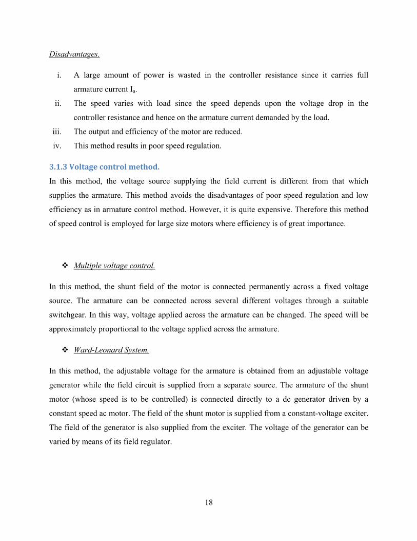
Field diverter.
In this method, a variable resistance (field diverter) is connected in parallel with series field
winding. Its effect is to shunt some portion of the line current from the series field winding, thus
weakening the field and increasing the speed. (N α 1 ).
The lowest speed obtainable is that corresponding to zero current in the diverter (i.e. diverter is
open). The lowest speed is hence the normal speed of the motor. Consequently, this method can
only provide speeds above the normal speed. The series field diverter method is often employed
in traction work.
Figure 3.3 Field diverter
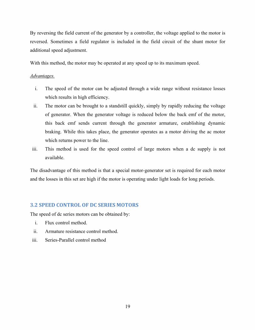
Armature diverter.
In order to obtain speeds below the normal speed available, a resistance (called armature
diverter) is connected in parallel with the armature. The diverter shunts some of the line current,
thus reducing the armature current. Now for a given load, if Ia is decreased, the flux Φ must
increase. Since N α1 , the motor speed is decreased. By adjusting the armature diverter, any
speed lower than the normal speed can be obtained.
21
Figure 3.4 Armature diverter
Tapped field control.
In this method, the flux is reduced (and hence speed is increased) by decreasing the number of
turns of the series field winding. The switch S can short circuit any part of the field winding, thus
decreasing the flux and raising the speed. With full turns of the field winding, the motor runs at
normal speed and as the field turns are cut out; speeds higher than normal speed are achieved.
Figure 3.5 Tapped field control
3.2.2 Armature resistance control.
In this method, a variable resistance is directly connected in series with the supply to the
complete motor. This reduces the voltage available across the armature and hence speed falls. By
changing the value of variable resistance, any speed below the normal speed can be obtained.
This is the most common method employed to control the speed of dc series motors.
22
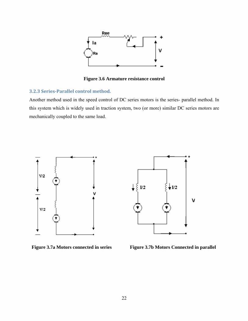
Figure 3.6 Armature resistance control
3.2.3 SeriesParallel control method.
Another method used in the speed control of DC series motors is the series- parallel method. In
this system which is widely used in traction system, two (or more) similar DC series motors are
mechanically coupled to the same load.
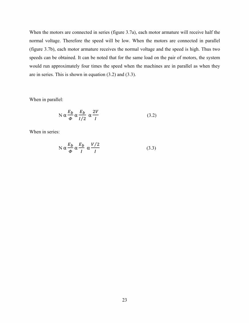
Figure 3.7a Motors connected in series Figure 3.7b Motors Connected in parallel
23
When the motors are connected in series (figure 3.7a), each motor armature will receive half the
normal voltage. Therefore the speed will be low. When the motors are connected in parallel
(figure 3.7b), each motor armature receives the normal voltage and the speed is high. Thus two
speeds can be obtained. It can be noted that for the same load on the pair of motors, the system
would run approximately four times the speed when the machines are in parallel as when they
are in series. This is shown in equation (3.2) and (3.3).
When in parallel:
N α α ⁄ α (3.2)
When in series:
N α α α ⁄
(3.3)
24
CHAPTER 4: FINAL DESIGN
The circuit was finally designed to meet the required objectives and specifications.
4.1 THEORY OF THE CIRCUIT
The purpose of the design was to come up with an inverter drive to control a dc motor by
variation of armature voltage. The motor to be controlled having a voltage rating of 110V DC yet
the supply available from the mains being 240V AC.
The inverter drive consists of an astable multi-vibrator (555 timer), that produces a 2 KHz square
wave pulse, a triac optical coupler that allows the pulse from the 555 timer to reach the switching
devices (MOSFETs) only when required. The configuration of the MOSFETs is such that they
switch in an anti-phase design such that when Q4 is ON, Q5 is OFF and vice-versa (see figure
4.1). The MOSFETs are connected to a high frequency centre-tapped transformer that has its
centre tap supplied by a dc voltage that has been rectified from the input ac mains. This produces
an ac voltage at the secondary of the transformer (Tx2). The output is then rectified and supplied
to the dc motor.
This output voltage is sampled and fed-back to the positive terminal of the voltage comparator
that also is connected to resistors R5, R4 and variable resistor R6 (figure 4.1). The negative
terminal of the voltage comparator is kept at a reference voltage (Vref) of 12V that is provided for
by the zener diode (D5) that is rated 12V. The voltage required at the output (Vout) is set by the
variable resistor R6.
This is shown in the equation (4.1), since R4 and R5 are fixed then the variable resistor R6 sets the
required voltage.
Vout = 12V 4 5 6 5 6
(4.1)
Should the voltage at the positive terminal of the comparator be less than the voltage at the
negative terminal (Vref) then the output of the comparator is taken to negative hence reverse
biasing the diode that is within the triac optical coupler IC. This turns ON the triac which allows
the pulse from the 555 timer to pass through.
25
On the positive pulse period, the signal passes through resistor R10 through to the N-P-N
transistor Q1. This then turns ON the P-N-P transistor Q3 allowing the MOSFET Q5 to be turned
ON. The rectified voltage from rectifier consisting of diodes D6, D7, D8 and D9 to the centre tap
of transformer (Tx2) hence now passes through the MOSFET Q5.
On the negative pulse period, the P-N-P transistor Q2 is turned ON this provides a gate signal to
the MOSFET Q4 which turns it ON. This action of switching between Q4 and Q5 produces an ac
voltage at the secondary of the high frequency transformer.
Should there be a change in load or some cause of voltage change such that the voltage at the
positive terminal of the comparator is higher than that at the negative terminal (Vref), then the
comparator swings to +Vcc hence forward biasing the diode that is within the triac optical
coupler. This turns OFF the triac, hence blocks the pulse from the 555 timer. The dc-ac
configuration that consists of the BJTs and MOSFETs is then turned OFF. This causes the
voltage at the output to decrease to the required voltage. Hence once the required voltage has
been set from the variable resistor R6 then the circuit is able to control itself due to the feedback
path provided.
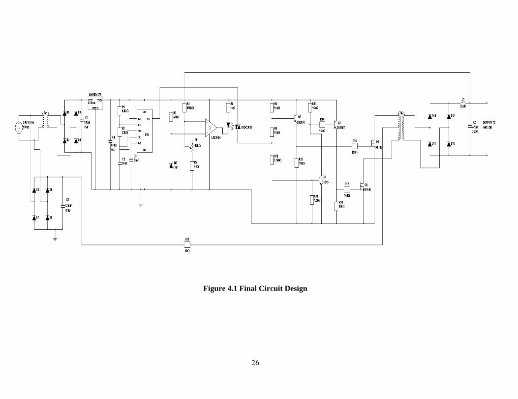
26
Figure 4.1 Final Circuit Design
27
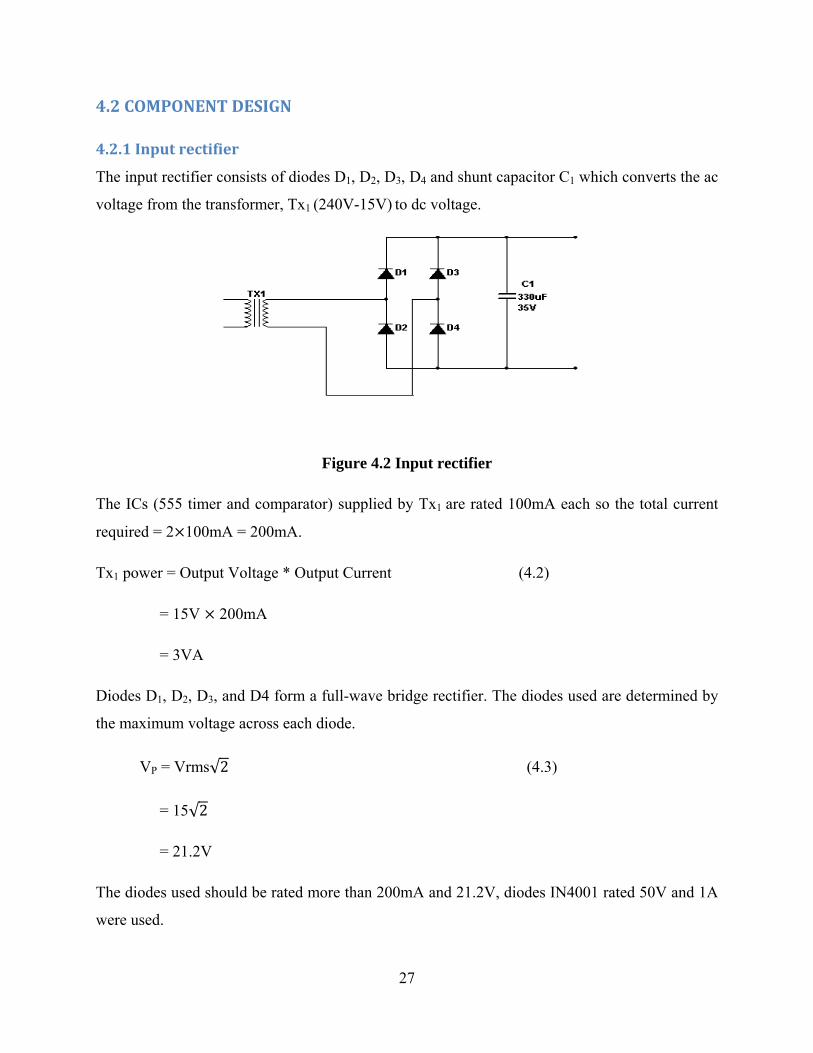
4.2 COMPONENT DESIGN
4.2.1 Input rectifier
The input rectifier consists of diodes D1, D2, D3, D4 and shunt capacitor C1 which converts the ac
voltage from the transformer, Tx1 (240V-15V) to dc voltage.
Figure 4.2 Input rectifier
The ICs (555 timer and comparator) supplied by Tx1 are rated 100mA each so the total current
required = 2 100mA = 200mA.
Tx1 power = Output Voltage * Output Current (4.2)
= 15V 200mA
= 3VA
Diodes D1, D2, D3, and D4 form a full-wave bridge rectifier. The diodes used are determined by
the maximum voltage across each diode.
VP = Vrms√2 (4.3)
= 15√2
= 21.2V
The diodes used should be rated more than 200mA and 21.2V, diodes IN4001 rated 50V and 1A
were used.
28
Capacitor C1 is a shunt capacitor filter. The minimum capacitor that could be used was
determined from the equation (4.4):
Vdc = (4.4)
With VP = 21.2, Idc = 200mA, f = 50Hz. The value of C can be found by substitution which is
114µf. The value used was 470µf with a voltage rating of 35V.
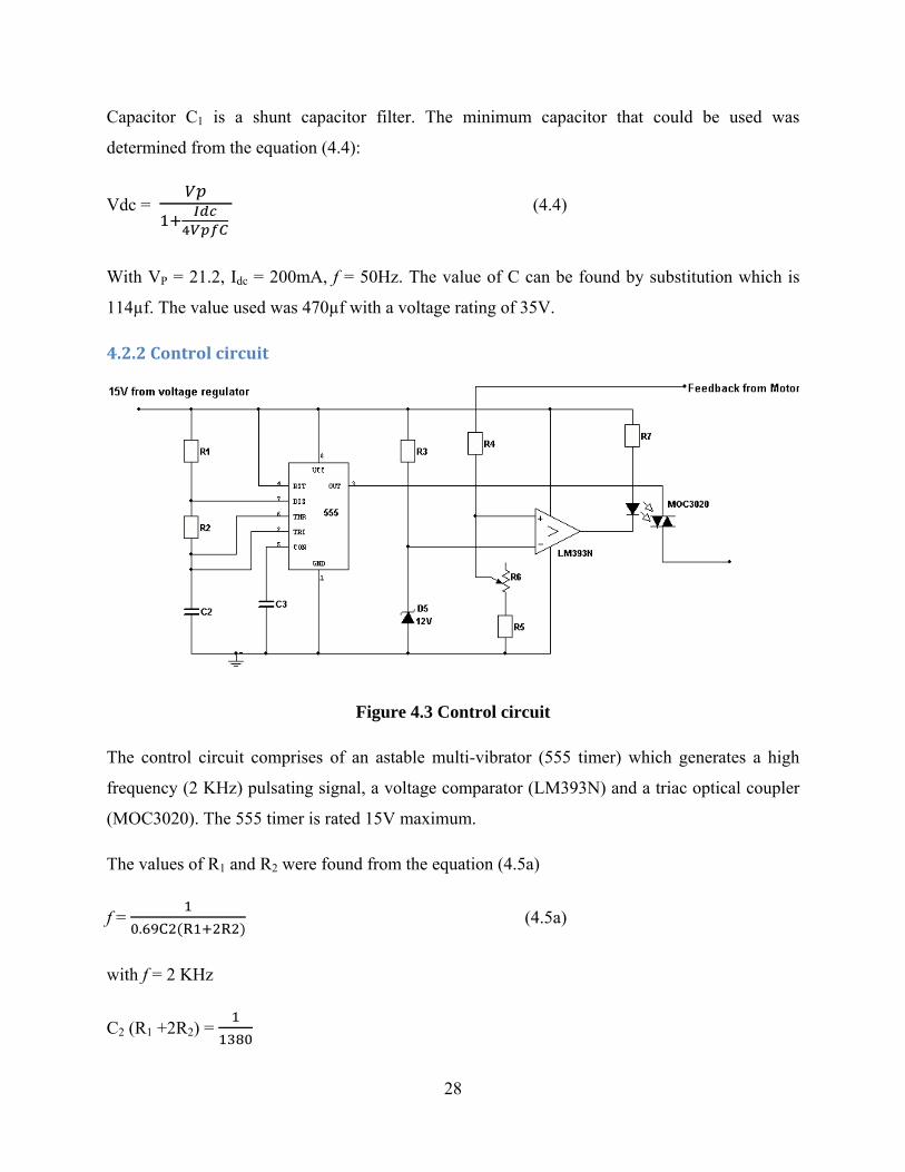
4.2.2 Control circuit
Figure 4.3 Control circuit
The control circuit comprises of an astable multi-vibrator (555 timer) which generates a high
frequency (2 KHz) pulsating signal, a voltage comparator (LM393N) and a triac optical coupler
(MOC3020). The 555 timer is rated 15V maximum.
The values of R1 and R2 were found from the equation (4.5a)
f = .
(4.5a)
with f = 2 KHz
C2 (R1 +2R2) =
29
Setting C2 to be 10nf, then
R1+ 2R2 = 72.5KΩ (4.5b)
To obtain a square wave signal, R2 should be greater than R1. Hence setting R1 to 6.8 KΩ,
substitution in equation (4.5b) gives R2 = 33K Ω.
The data sheet recommends that voltage control terminal be connected to ground via a 10nf
decoupling capacitor C3 = 10nf.
R3 and D5 set a reference voltage. A reference voltage of 12V is set by the zener diode D5. D5 is
BZX79C12 rated Vz = 12V and Iz = 5mA.
R3 = = = 600Ω
Hence R3 design is 680Ω.
R4, R5 and R6 sample the output voltage to the motor. The voltage drop across R6 and R5 at 110V
(this is the rated voltage of the dc motor), should be equal to the reference voltage (12V).
110V 12V (4.6a)
0.11 (4.6b)
To get the maximum voltage output the variable resistor (R6) is set at a minimum (zero) hence
equation (4.6b) becomes:
0.11
R5= 0.11(R4 + R5)
Setting R4 = 470KΩ then R5= 56 KΩ.
To attain a lower voltage, the value of the variable resistor (R6) is increased. At a lower scale, to
obtain a voltage of 50V:
30
50V = 12V (4.7a)
= 0.24 (4.7b)
By substitution R6 = 87KΩ, Potentiometer available = 100KΩ
The triac optical coupler is used to allow the pulse from the 555 timer to the inverter when the
voltage drop across resistors R5 and R6 is less than the reference voltage. The optical coupler
MOC3020 rated If 15mA. Therefore the resistor R7 has a value of 1KΩ.
R7 = (4.8)
= = 1 KΩ
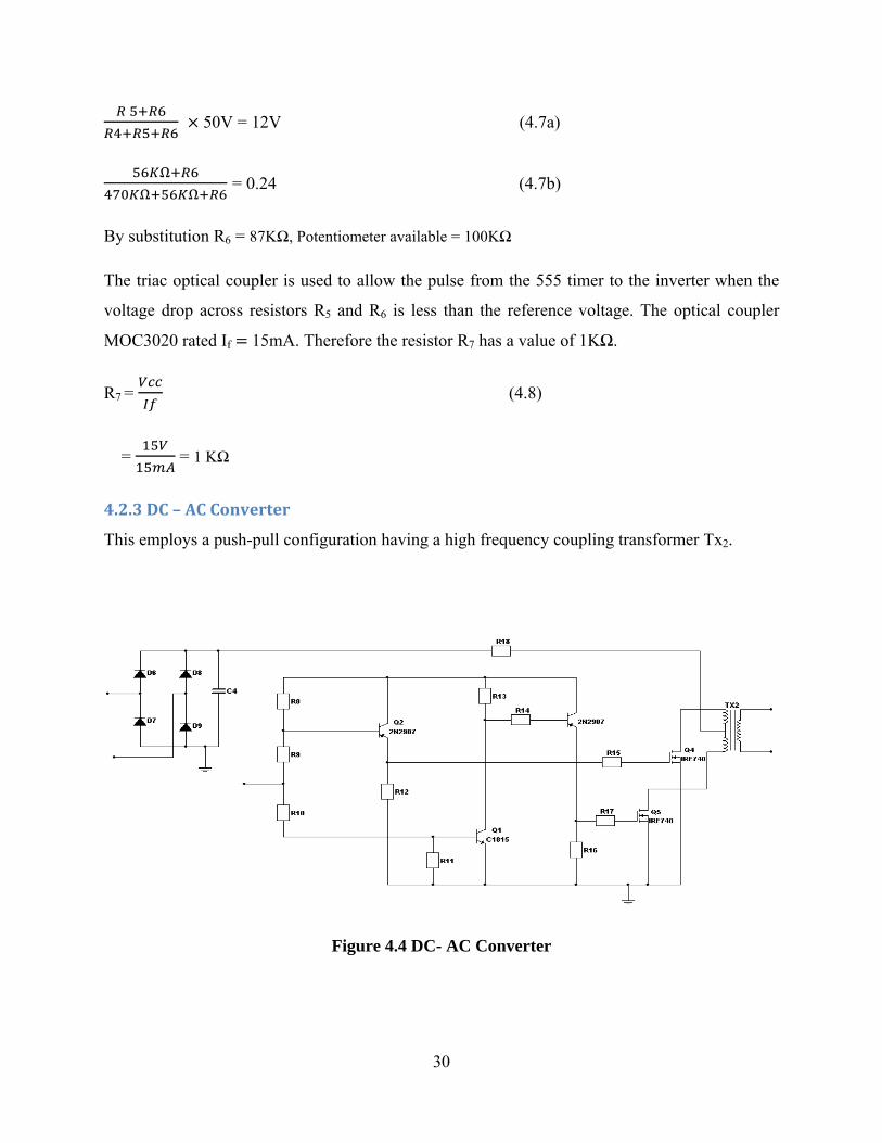
4.2.3 DC – AC Converter
This employs a push-pull configuration having a high frequency coupling transformer Tx2.
Figure 4.4 DC- AC Converter
31
The transformer which is centre tapped at the primary is fed from the input rectifier made up of
diodes D6, D7, D8 and D9. The diodes used were determined by the maximum voltage across
each diode.
VP = 240√2 =339V.
The output current = 9A.
Output power = Output Voltage Output Current
= 110V 9A
= 990VA
Supply current =
= = 4.125A
C4 is the shunt capacitor filter. Its value was determined by substitution in equation (4.4). A
capacitor of 330µf and voltage rating of 470V was used.
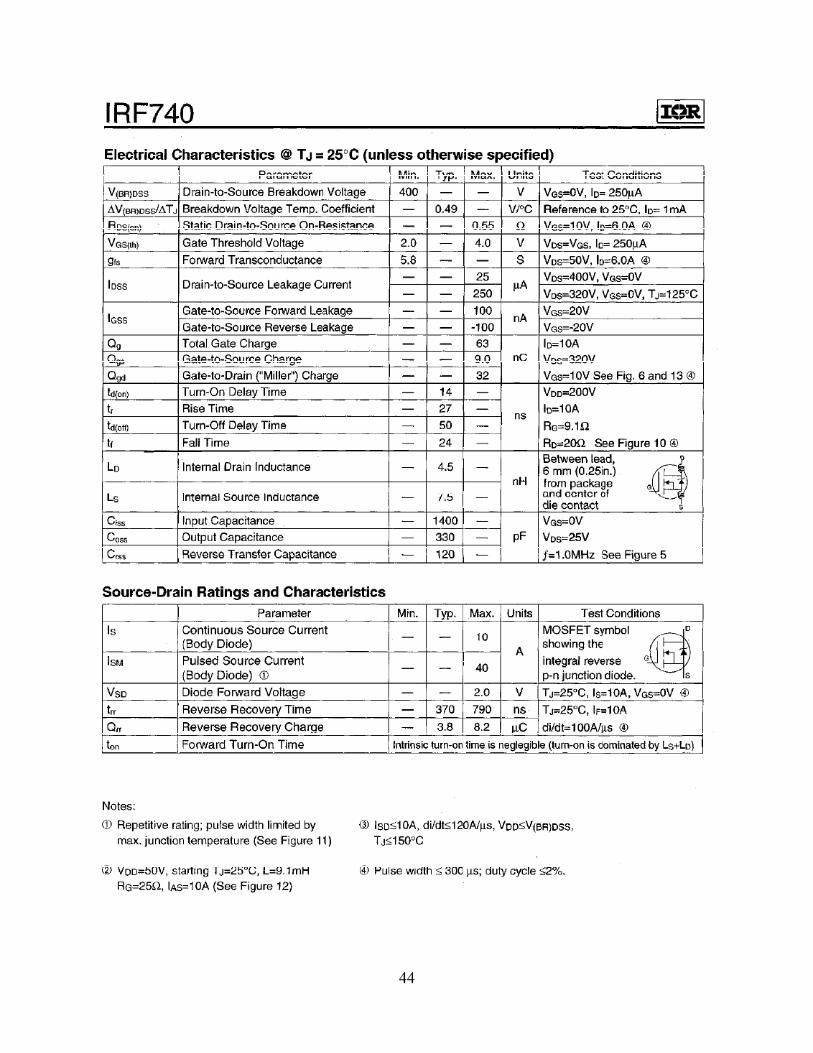
The MOSFETs Q4 and Q5 are IRF740 rated 10A and 400V VDS max.
Transistors Q2 and Q3 should be rated more than 100mA. Transistor 2N2907 rated 600mA was
used. Resistors R12 and R16 were used to ground all leakage currents flowing through the
transistors.
R12, R16 = = = 150Ω
R9, R14 =
IB = = = 1mA
Therefore;
R9, R14 = = 15KΩ
32
The current flowing through the base of Q3 is the collector current flowing through Q1. The
transistor C1815 rated 100mA and hfe 100 was used for Q1.
R13 = = = 15KΩ
R10 =
IB = = = 10µA
R10 = = 1.5MΩ
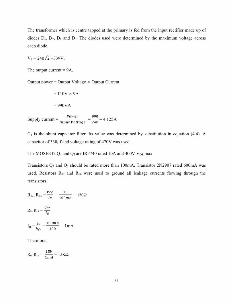
4.2.4 Rectifier and filter
This consists of full-wave bridge rectifier and L-C filter.
Figure 4.5 Output rectifier
33
Diodes D10, D11, D12 and D13 form a full-wave bridge rectifier. The diodes used are determined
by the maximum voltage across each diode. The diodes used were rated 800Vmax. The inductor
L1 and capacitor C5 form the L-C filter. The filter should be such that the ripple factor is 1%.
r = 1.19 LC (4.9)
0.01 = 1.19 LC
LC = 0.0084
Selecting an inductance of 22µH for L,
C = .
= 382µf
Therefore a capacitance of 470µf with a voltage rating of 250V was chosen.
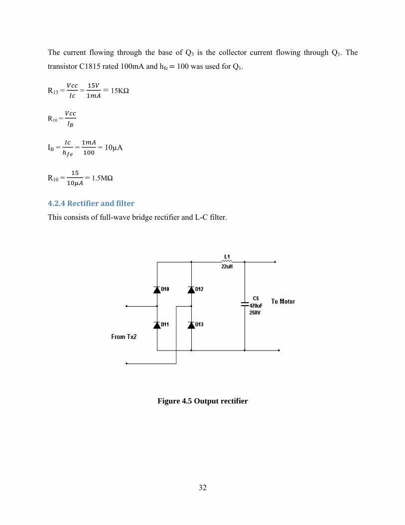
The figure 4.6 shows the constructional details of the inverter drive.
Figure 4.6 inverter drive designed
34
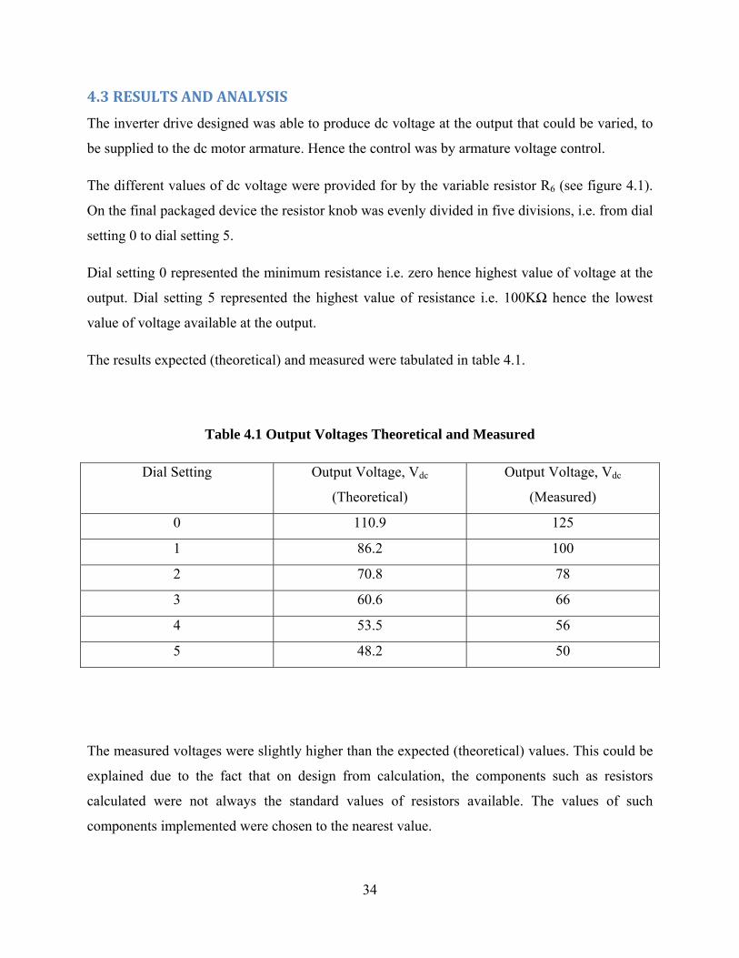
4.3 RESULTS AND ANALYSIS
The inverter drive designed was able to produce dc voltage at the output that could be varied, to
be supplied to the dc motor armature. Hence the control was by armature voltage control.
The different values of dc voltage were provided for by the variable resistor R6 (see figure 4.1).
On the final packaged device the resistor knob was evenly divided in five divisions, i.e. from dial
setting 0 to dial setting 5.
Dial setting 0 represented the minimum resistance i.e. zero hence highest value of voltage at the
output. Dial setting 5 represented the highest value of resistance i.e. 100KΩ hence the lowest
value of voltage available at the output.
The results expected (theoretical) and measured were tabulated in table 4.1.
Table 4.1 Output Voltages Theoretical and Measured
Dial Setting Output Voltage, Vdc
(Theoretical)
Output Voltage, Vdc
(Measured)
0 110.9 125
1 86.2 100
2 70.8 78
3 60.6 66
4 53.5 56
5 48.2 50
The measured voltages were slightly higher than the expected (theoretical) values. This could be
explained due to the fact that on design from calculation, the components such as resistors
calculated were not always the standard values of resistors available. The values of such
components implemented were chosen to the nearest value.

35
The results (table 4.1) show that the circuit implemented could be used as an inverter drive for a
dc motor. This could be used in situations where varying values of dc voltage are required but
what is available from the supply is 240 Vac mains supply. The tabulated results also show that
the inverter drive is capable of providing voltage of between 50Vdc to 125Vdc.
36
CHAPTER 5: CONCLUSION
From the results obtained (table 4.1), the circuit designed was capable of providing speed control
of a dc motor by producing varying dc voltage of between 50V and 125V. This dc voltage being
supplied to the armature winding of the dc motor.
A survey of the control of dc motors by conventional methods was carried out and the three main
methods of control i.e.
• Varying the flux per pole
• Varying the resistance of the armature circuit.
• Varying the applied voltage
were studied as required in the objectives of the project.
The implementation of the project provided valuable knowledge of dc motors in general and how
their control is useful in the industrial field. It also gave a good understanding of the
conventional control concepts used in the control of dc motors.
5.1 RECOMMENDATIONS AND FURTHER WORK
1. Diodes should be added to the existing diodes (D10, D11, D12 and D13) in parallel hence
enable the device handle more current and a motor with a bigger power rating.
2. The circuit could be further improved by implementing one that controls a specific dc
motor, such that the output voltage of the inverter drive and the corresponding speed of
the dc motor monitored. A digital display can hence be provided for showing the voltage
and exact speed of the dc motor.
37
REFERENCES
1. Rudolf F. Graf, Williams Sheets, The Encyclopedia of Electronic Circuits Vol.4, © 1992
McGraw-Hill Professional
2. V.K Mehta, Rohit Mehta, Principles of Electrical Machines, © 2002 S.Chand &
Company Ltd. 7361, Ram Nagar, New Delhi-110 055, Printed by Rajenda Ravindra
Printers (Pvt.) Ltd., 7361, Ram Nagar New Delhi-100 055
3. B. L. Theraja, A Textbook of Electrical Technology, © 2005 S. Chand & Company Ltd.
7361, Ram Nagar, New Delhi-110 055, Printed by Rajenda Ravindra Printers (Pvt.) Ltd.,
7361, Ram Nagar New Delhi-100 055
4. S K Bhattacharya, S Chatterjee, Industrial Electronics & Control, © 1995 Tata McGraw-
Hill
5. Hughes Austin, Electric Motors and Drives: Fundamentals, types and applications, ©
1990 Newnes, Printed by Biddles Ltd

38
APPENDIX : DATA SHEETS
39
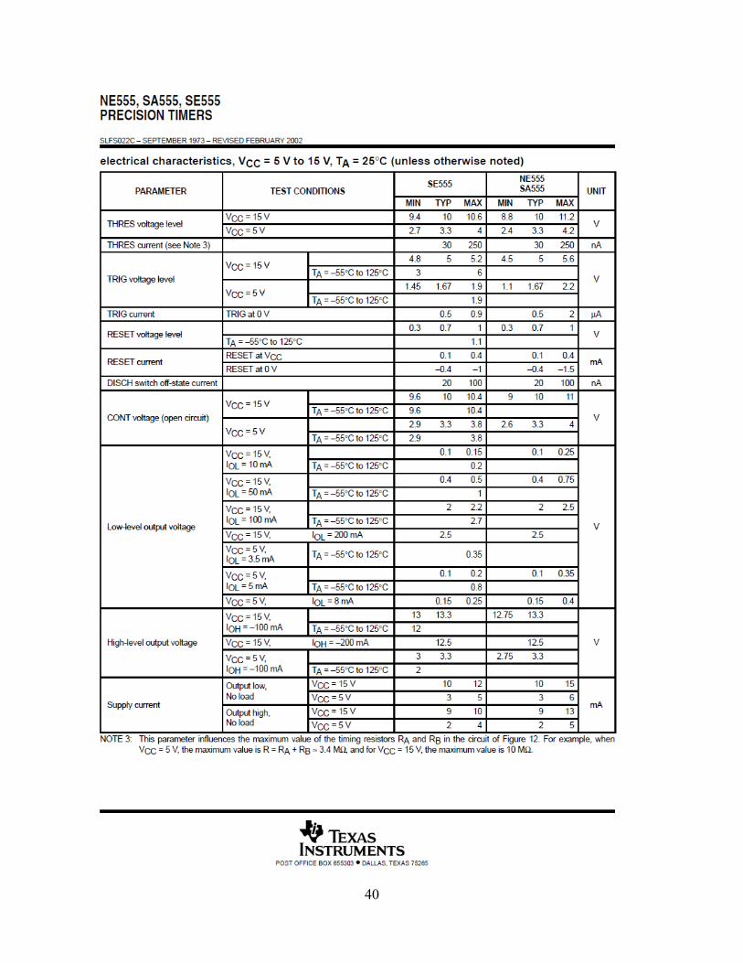
40
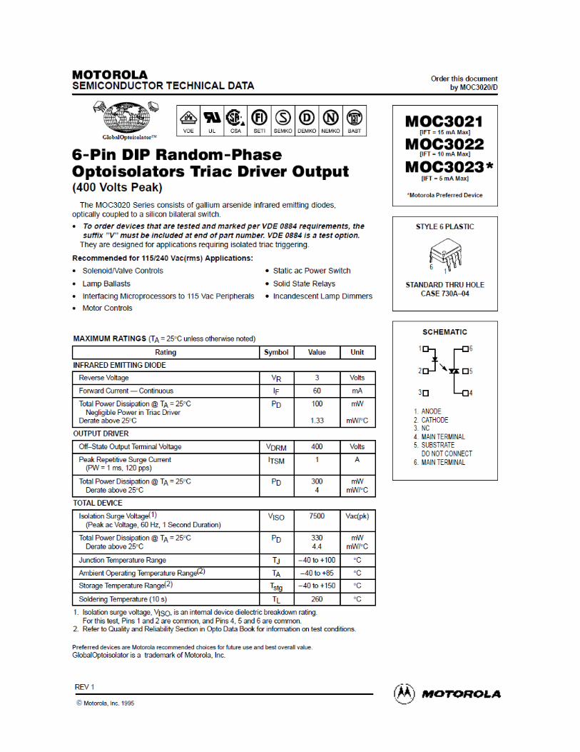
41
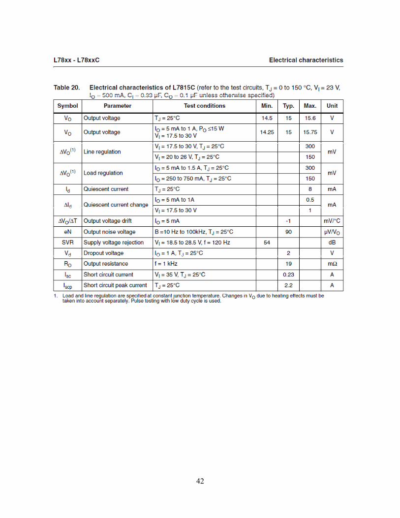
42
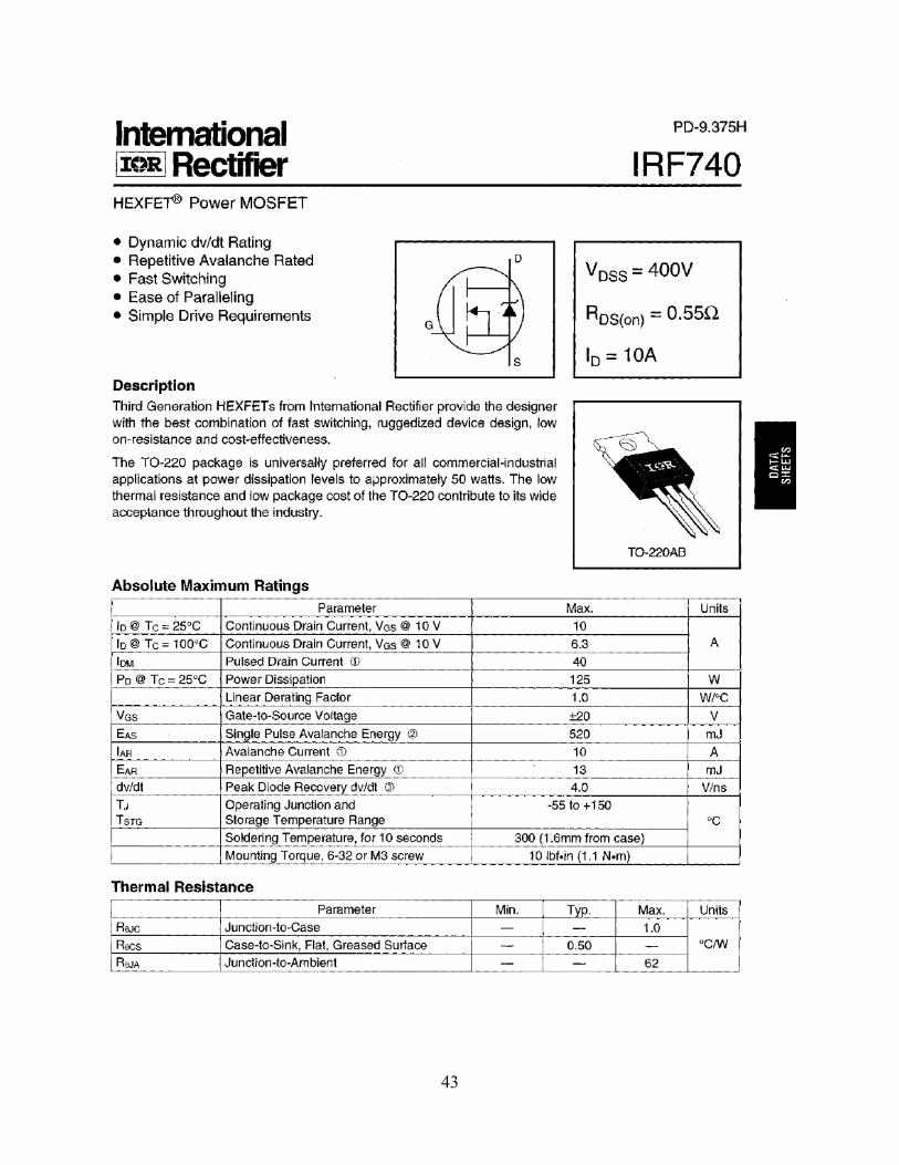
43
44