Embed Size (px)
Citation preview

University of WaterlooDepartment of Mechanical Engineering
ME 322 ME 322 -- Mechanical Design 1Mechanical Design 1
Partial notes – Part 6 (Welded Joints)(G. Glinka)
Fall 2005

1. Introduction to the Static Strength Analysis 1. Introduction to the Static Strength Analysis of Welded Jointsof Welded Joints
• The structural nature of welded joints• Static strength of weldments• The customary American method (AWS)• Simple welded joint analysis• Example

ComponentGeometry Loading
Stress-StrainAnalysis
Strength Analysis
Allowable Load / Fatigue Life
MaterialProperties
Information path in strength and fatigue life prediction procedures
StrengthStrength--Fatigue Analysis ProcedureFatigue Analysis Procedure
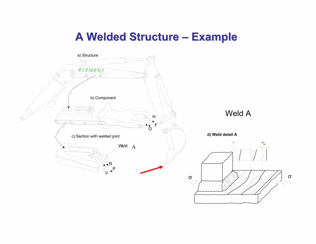
A Welded Structure A Welded Structure –– ExampleExample
VP
Q
R
H
F
Weld
a) Structure
b) Component
c) Section with welded joint
A n
d) Weld detail A
Weld A
σσ

Load configuration and the global Load configuration and the global bending moment distribution along bending moment distribution along segments of telescopic crane boomsegments of telescopic crane boom

12
b)
F F
Segment No. 2c)
a) Load configuration in twoa) Load configuration in two--segment telescopic crane boom, b) welded segment telescopic crane boom, b) welded box cross section of the boom, c) out of plane web deflections obox cross section of the boom, c) out of plane web deflections of the boom f the boom box cross sectionbox cross section

g =
hl = hp
Butt welded jointButt welded joint
=tp hp
t
TT--joint with fillet weldsjoint with fillet welds
(V.A. Ryakhin et.al., ref. 29)
Typical geometrical weld configurationsTypical geometrical weld configurations
© 2004 Grzegorz Glinka. All rights reserved. Page 8
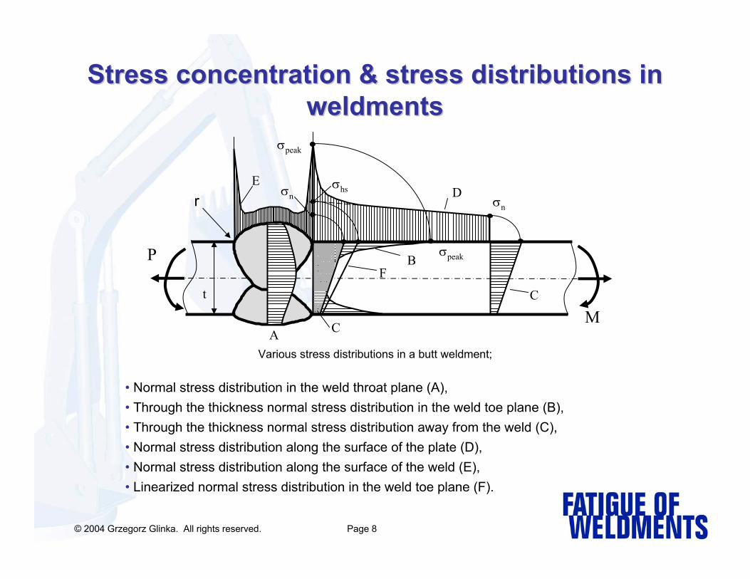
Stress concentration & stress distributions in Stress concentration & stress distributions in weldmentsweldments
Various stress distributions in a butt weldment;
r
A
B
C
DE
P
M
F
σpeak
σhs
σn
σpeak
t
C
σn
• Normal stress distribution in the weld throat plane (A), • Through the thickness normal stress distribution in the weld toe plane (B), • Through the thickness normal stress distribution away from the weld (C),• Normal stress distribution along the surface of the plate (D),• Normal stress distribution along the surface of the weld (E), • Linearized normal stress distribution in the weld toe plane (F).

Various stress distributions in a T-butt weldment with transverse fillet welds;
r
t
t1
ED
BC
A
σpeak
σn
σhs
FP
M
C
Θ
• Normal stress distribution in the weld throat plane (A), • Through the thickness normal stress distribution in the weld toe plane (B), • Through the thickness normal stress distribution away from the weld (C),• Normal stress distribution along the surface of the plate (D),• Normal stress distribution along the surface of the weld (E), • Linearized normal stress distribution in the weld toe plane (F).
Stress concentration & stress distributions in Stress concentration & stress distributions in weldmentsweldments

Stress components in the weld throat cross Stress components in the weld throat cross section of butt weldmentsection of butt weldment
P
R
στ
L
t
R
P
σ = P/A
τ = R/A
Resultant equivalent stress
( )2223eqσ σ τ= +
A = t·L
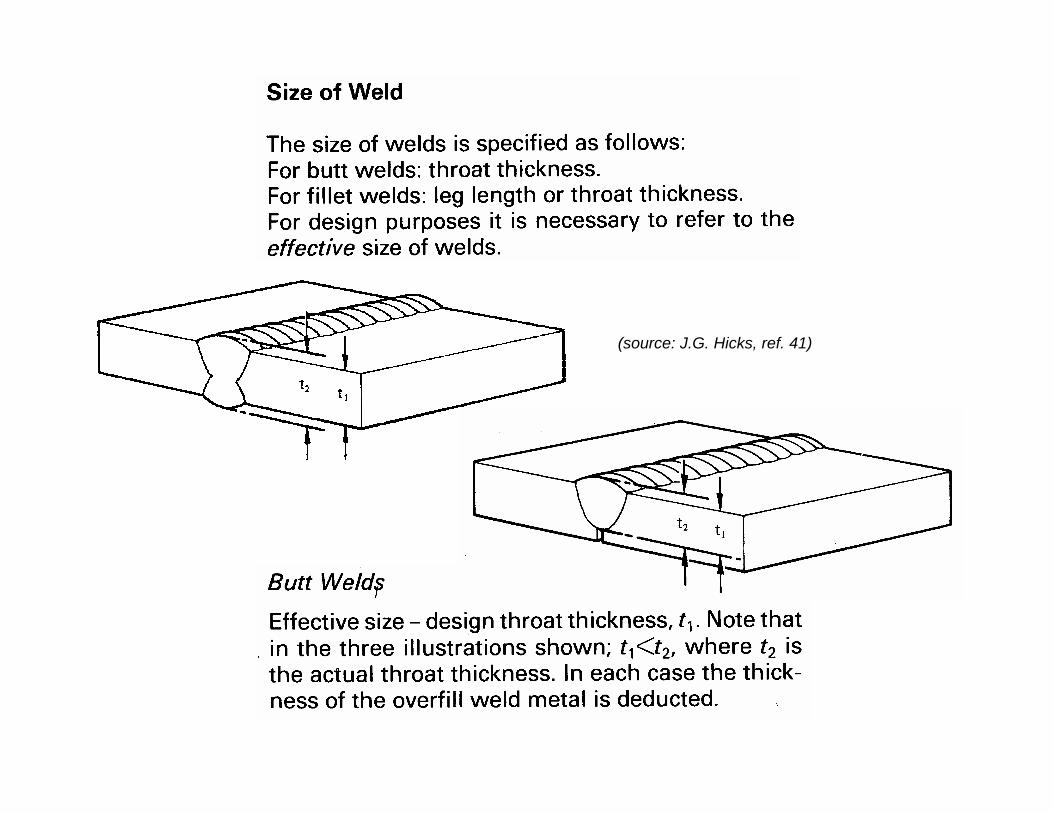
(source: J.G. Hicks, ref. 41)

(source: J.G. Hicks, ref. 41)

Static strength analysis of weldmentsStatic strength analysis of weldments•The static strength analysis of weldments requires the determination of stresses in the load carrying welds. •The throat weld cross section is considered to be the critical section and average normal and shear stresses are used for the assessment of the strength under axial, bending and torsion modes of loading. The normal and shear stresses induced by axial forces and bending moments are averaged over the entire throat cross section carrying the load. •The maximum shear stress generated in the weld throat cross section by a torque is averaged at specific locations only over the throat thickness but not over the entire weld throat cross section area.
NonNon--load load carrying weldscarrying welds
Load carrying welds

(source: J.G. Hicks, ref. 41)
Welds withequal legs
Welds withunequal legs
Definition of the weld throat thickness for Definition of the weld throat thickness for various geometrical weld configurationsvarious geometrical weld configurations

RV
P
L
t
R
V
P
TT-- butt weldment with nonbutt weldment with non-- loadload--carrying transverse carrying transverse fillet welds fillet welds (static strength analysis not required!)(static strength analysis not required!)
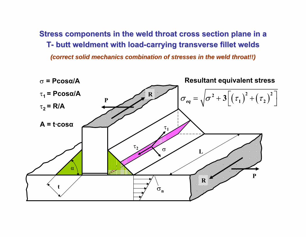
Stress components in the weld throat cross section plane in a Stress components in the weld throat cross section plane in a TT-- butt weldment with loadbutt weldment with load--carrying transverse fillet weldscarrying transverse fillet welds
(correct solid mechanics combination of stresses in the weld thr(correct solid mechanics combination of stresses in the weld throat!!)oat!!)
τ1
στ2
RP
L
t
RP
σn
σ = Pcosα/A
τ1 = Pcosα/A
τ2 = R/A
A = t·cosα
α
Resultant equivalent stress
( ) ( )2 221 23eqσ σ τ τ⎡ ⎤= + +⎣ ⎦

Stress components in the weld throat cross section plane in a Stress components in the weld throat cross section plane in a TT-- butt weldment with loadbutt weldment with load--carrying transverse fillet weldscarrying transverse fillet welds
(simplified combination of stresses in the weld throat cross sec(simplified combination of stresses in the weld throat cross section according tion according to the customary American method !!)to the customary American method !!)
σ = 0 !!
τ1=P/A
τ2=R/a
Calculation of the transverse shear stress
τ1= σX=P/A
τ1
σxτ2
RP
L
t
RP
σn
α
( ) ( )2 21 2τ τ τ= +
23eqσ τ=
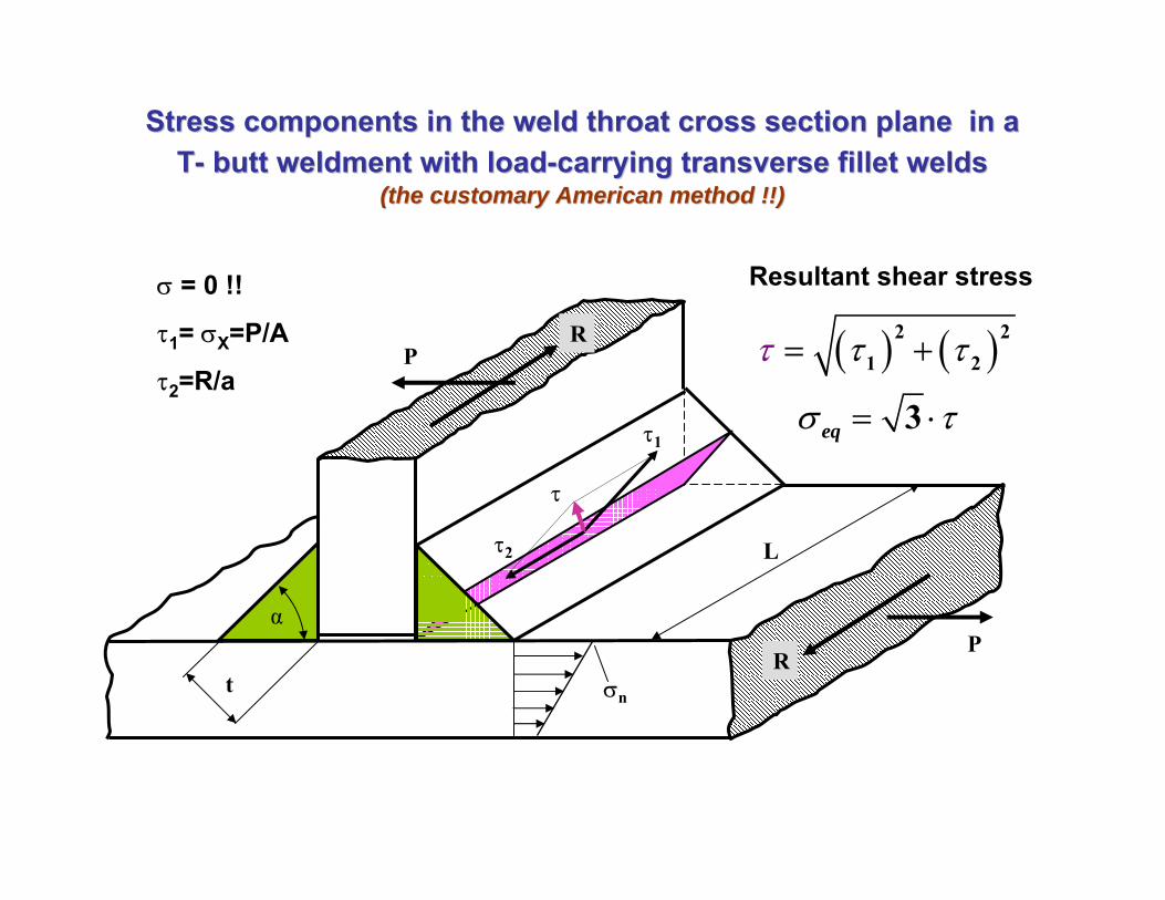
Stress components in the weld throat cross section plane in a Stress components in the weld throat cross section plane in a TT-- butt weldment with loadbutt weldment with load--carrying transverse fillet weldscarrying transverse fillet welds
(the customary American method !!)(the customary American method !!)
τ1
τ2
RP
L
t
RP
σn
Resultant shear stress
α
( ) ( )2 21 2
3eq
τ τ
σ
τ
τ
= +
= ⋅
σ = 0 !!
τ1= σX=P/A
τ2=R/a
τ

© 2004 Grzegorz Glinka. All rights reserved. Page 19
τ1
1 2
2 cos
2 cos 45
1.414
xPlt
Plh
Plh
Plh
τ σ
θ
= =
=
=
=
o
13
31.41
.2254
1
eq
Plh
Plh
σ τ= =
≈
σx
σx
P/2
t
θ
P/2
EXAMPLE: Transverse fillet weld under axial loadingEXAMPLE: Transverse fillet weld under axial loading
ht
b
d
l
V
α
a)
τ1,M = σM M
σM
σM
c)
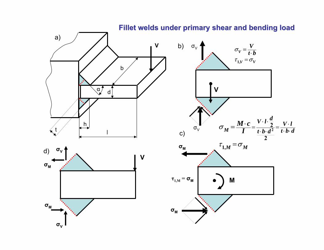
Fillet welds under primary shear and bending loadFillet welds under primary shear and bending load
σV
V
σVb)
1,
V
VV
Vt bσ
τ σ
=⋅
=
2
1,
2
2M
MM
dV l V lt b dt b d
M cIσ
τ σ
⋅ ⋅ ⋅= = ⋅ ⋅⋅ ⋅⋅=
=σV
σV
σM
V
σM
d)
© 2004 Grzegorz Glinka. All rights reserved. Page 21
d)
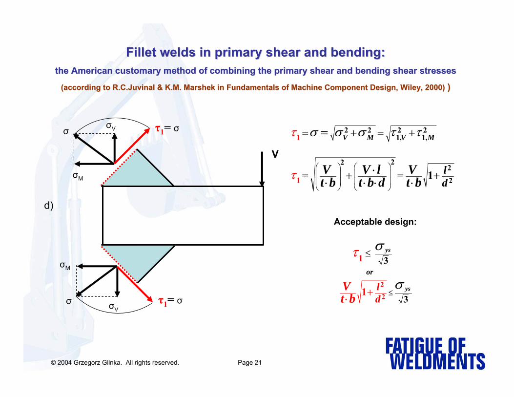
Fillet welds in primary shear and bending:Fillet welds in primary shear and bending:the American customary method of combining the primary shear andthe American customary method of combining the primary shear and bending shear stressesbending shear stresses
(according to (according to R.C.JuvinalR.C.Juvinal & K.M. & K.M. MarshekMarshek in Fundamentals of Machine Component Design, Wiley, 2000)in Fundamentals of Machine Component Design, Wiley, 2000) ))
σV
σM
V
σ τ1= σ
σV
σM
σ τ1= σ
2 2 2 21, 1,
222
2
1
1 1
V M V M
ld
V V l Vt b t b d t b
τ
τ
σ σ σ τ τ
⎛ ⎞⎛ ⎞⎜ ⎟⎜ ⎟⎜ ⎟⎜ ⎟
⎝ ⎠ ⎝ ⎠
= + = +
= + = +
=
⋅⋅ ⋅ ⋅ ⋅
Acceptable design:
2
2
1 3
31
ys
ys
or
ld
Vt b
στ
σ≤
≤
+⋅

Idealization of welds in a TIdealization of welds in a T-- butt welded joint; a) geometry and butt welded joint; a) geometry and loadings, b) and c) position of weld lines in the model for loadings, b) and c) position of weld lines in the model for
calculating stresses under axial, torsion and bending loadscalculating stresses under axial, torsion and bending loads
Mb
Tr
b Weldline
Weldline
b)
c)
r
2c
r
d
a)
t
d
Tr
b
Mb
h
P
;2
;2 2r
bP b
w
rT
w
M cPtd I
T r d bc orJ
σ σ
τ
⋅= =
⋅= =
r
2c2c
2c
P
b

It is customary assumed that stresses in the weld throat cross section induced by bending
and torsion loads can be treated as lines of thickness ‘t’ and length ‘d’. The bending normal
stresses are subsequently calculated using the simple bending formula.
bb
w
M cI
σ =
The moment of inertia Ix and Iy are calculated for the entire group of welds carrying the
bending moment, assuming that they are lines of thickness ‘t’. In the case of the two welds
shown in the Figure above the moments of inertia are: 3 2 3
, ,6 2 6w y w xd t t d b t dI and I⋅ ⋅ ⋅ ×
= + =
Parameter ‘c’ is the distance from the neutral axis to the point on the weld line furthest from
the neutral axis of the group of welds being analyzed. In the case of the two welds shown in
the Figure it is:
2 2b dc or c= =

The shear stress induced by a torque is calculated using the simple shear stress formula:
r
rT
w
T rJ
τ =
The polar moment of inertia, Jw, is calculated for the entire group of welds carrying the
torque, assuming that they are lines as defined above. In the case of the two welds shown
in the Figure the polar moment of inertia is:
( )2 23 36 6w
td b dd tJ+⋅
= +
Parameter ‘r’ is the distance from the center of gravity of the group of welds being analyzed
to the furthest point on the weld line. In the case of the two welds shown in the Figure it is
the distance from the gravity center of the group of welds to the end of the weld:
2 2
2 2d br ⎛ ⎞ ⎛ ⎞= +⎜ ⎟ ⎜ ⎟
⎝ ⎠ ⎝ ⎠

Weld configurationsWeld configurations
0.707 ;u uJ t J h J= × = ×
t - weld throat thicknessIu - unit axial area moment of inertia, [m3]
Ju - unit polar area moment of inertia, [m3]
Unit moments of area of typical weld groupsUnit moments of area of typical weld groups
0 707. ;u uI t I h I= × = ×
From: B.J. Hamrock, ref.(26)
3
12udI =
3
6udI =
2
2ub dI ⋅
=
Note!Note!The handbook ready made formulas for the unit area moments of inertia are approximate! The terms (bt3) or (dt3) are sometimes omitted when the parallel axis theorem is used!
It should be for example (the bottom case):
3 2
6 2b t b t dI ⋅ ⋅ ⋅
= +
2 2
6 2 2ub b d b dI ⋅ ⋅
= + ≈
for t =1

P =
T
Shear stresses induced by the the direct force P
Shear stresses induced by the the torque T
( ) ( )T PTP2
1 212
2τ ττ ττ = + + +
Resultant shear stress
τ2P
τ1P
x
y
τ1T
τ2T
τ2T
τ1T
y Stresses in welds under torsion Stresses in welds under torsion and direct shear loads onlyand direct shear loads only
( )3r
ysT V P M yield
στ τ τ σ σ τ= + + + < =
P
M
Tr
z
x
y
a)
r
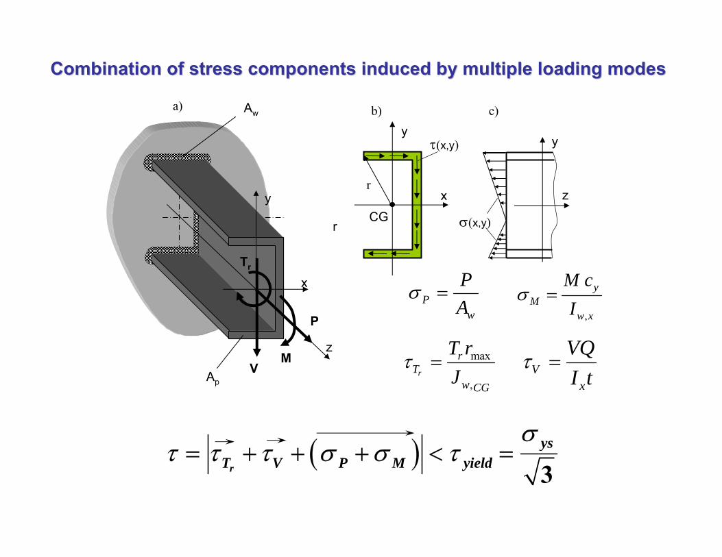
Aw
ApV
Pw
PA
σ =,
yM
w x
M cI
σ =
max
,r
rT
w CG
T rJ
τ = Vx
VQI t
τ =
τ(x,y)
x
y
CG
b)
y
z
σ(x,y)
c)
r
Combination of stress components induced by multiple loading modCombination of stress components induced by multiple loading modeses

The American customary method: It is assumed that the weld throat is in shear for all types of load and the shear stress in the weld throat is equal to the normal stress induced by bending moment and/or the normal force and to the shear stress induced by the shear force and/or the torque. There can be only two shear stress components acting in the throat plane - namely τ1 and τ2 . Therefore the resultant shear stress can be determined as:
2 21 2τ τ τ= +
The weld is acceptable if :
3ys
ys
στ τ< =
Where: τys is the shear yield strength of the: weld metal for fillet welds and parent metal for butt welds
Static Strength Assessment of Fillet WeldsStatic Strength Assessment of Fillet Welds