Embed Size (px)
Citation preview
University of Dundee
DOCTOR OF PHILOSOPHY
The use of CAD CAM For Fixed Partial Prostheses
Almustafa, Nawaf Mohammed
Award date:2016
Link to publication
General rightsCopyright and moral rights for the publications made accessible in the public portal are retained by the authors and/or other copyright ownersand it is a condition of accessing publications that users recognise and abide by the legal requirements associated with these rights.
• Users may download and print one copy of any publication from the public portal for the purpose of private study or research. • You may not further distribute the material or use it for any profit-making activity or commercial gain • You may freely distribute the URL identifying the publication in the public portal
Take down policyIf you believe that this document breaches copyright please contact us providing details, and we will remove access to the work immediatelyand investigate your claim.
Download date: 02. Dec. 2021
The use of CAD CAM
For
Fixed Partial Prostheses
Nawaf Mohammed Almustafa
DDS, MDSc
A thesis submitted for the degree of Doctor of Philosophy
University of Dundee
19. February, 2016

ii
لْمًا دْنِّي عِّ ِّ زِّ ب وَقلُ رَّ
"O my Lord! Advance me in knowledge."
TaHa (20:114) سورة طه
i
Table of Contents Table of Contents ............................................................................................................................ i
List of Tables .................................................................................................................................. v
List of Figures ............................................................................................................................... vii
Acknowledgements ........................................................................................................................ x
Declaration .................................................................................................................................... xi
Certificate ..................................................................................................................................... xii
Certificate .................................................................................................................................... xiii
Abstract ........................................................................................................................................ xv
Chapter 1 ....................................................................................................................................... 1
Introduction and literature Review .............................................................................................. 1
1.1 General Introduction ........................................................................................................... 2
1.2 Indications for indirect dental restoration .......................................................................... 3
1.3 Dental materials used for indirect dental restoration ........................................................ 3
1.3.1 All metal indirect restorations ..................................................................................... 3
1.3.2 Metal ceramic crowns .................................................................................................. 8
1.3.3 Veneering Ceramics and its techniques ....................................................................... 9
1.3.4 Bonding ceramics to metal alloys .............................................................................. 11
1.3.5 All ceramic dental restorations .................................................................................. 13
1.4 Ceramics ............................................................................................................................ 16
1.4.1 Dental ceramic composition ...................................................................................... 17
1.4.2 Ceramic properties ..................................................................................................... 18
1.4.3 Classification of dental ceramics ................................................................................ 18
1.5 Zirconium .......................................................................................................................... 27
1.5.1 Stages when zirconia milling can take place .............................................................. 30
1.5.2 Survival of zirconia ..................................................................................................... 32
1.6 CAD CAM ........................................................................................................................... 35
1.6.1 History of dental CAD CAM ........................................................................................ 35
1.6.2 CAD CAM components ............................................................................................... 38
1.6.3 CAD CAM classification .............................................................................................. 52
1.6.4 Advantages of using CAD CAM .................................................................................. 55
1.6.5 Materials available for the use with CAD CAM .......................................................... 55
1.6.6 Work Flow to construct dental restorations .............................................................. 58
1.6.7 CAD-on veneering technique ..................................................................................... 60
1.7 Tooth preparation design ................................................................................................. 61
1.7.1 Amount of tooth reduction ........................................................................................ 62
ii
1.7.2 Finish-line ................................................................................................................... 63
1.7.3 Retention and Resistance .......................................................................................... 67
1.7.4 Preparation taper ....................................................................................................... 68
1.7.5 Line angle form .......................................................................................................... 69
1.7.6 Surface texture ........................................................................................................... 69
1.8 Impressions....................................................................................................................... 70
1.8.1 Conventional and Digital Impression/Digital scanning ............................ 72
1.8.2 Cross infection control in relation to impressions .................................... 73
1.8.3 Models .................................................................................................................... 74
1.8.4 Rapid prototyping ............................................................................................... 75
1.8.5 Stereolithography (SLA) .................................................................................... 77
1.8.6 Dental application of rapid prototyping ...................................................... 77
1.9 Cements ............................................................................................................................ 78
1.9.1 Ideal properties of a luting cement ............................................................... 79
1.9.2 Classification of dental cements ..................................................................... 79
1.10 Literature review conclusion and overall aim ................................................................. 82
1.11 Sample size calculation ................................................................................................... 83
Chapter 2 ..................................................................................................................................... 84
Laboratory study 1 ...................................................................................................................... 84
Force applied by dentists during cementation of all zirconia three unit bridges and the impact
on seating .................................................................................................................................... 84
2.1 Introduction ...................................................................................................................... 85
2.2 Aims and objectives .......................................................................................................... 86
2.3 Material and Methods ...................................................................................................... 86
2.4 Results ............................................................................................................................. 104
2.5 Discussion ........................................................................................................................ 108
2.6 Conclusions ..................................................................................................................... 115
Chapter 3 ................................................................................................................................... 116
Laboratory study 2 .................................................................................................................... 116
The effect of firing cycles and zirconia thickness on the internal and marginal fit of zirconia
bridges....................................................................................................................................... 116
3.1 Introduction .................................................................................................................... 117
3.2 Aims and objectives ........................................................................................................ 118
3.3 Material and Methods .................................................................................................... 119
3.4 Results ............................................................................................................................. 126
3.5 Discussion ........................................................................................................................ 130
3.6 Conclusions ..................................................................................................................... 137
iii
Chapter 4 ................................................................................................................................... 139
Laboratory study 3 .................................................................................................................... 139
Three unit all zirconia bridges versus four unit all zirconia bridges ......................................... 139
4.1 Introduction .................................................................................................................... 140
4.2 Aims and objectives ........................................................................................................ 141
4.3 Material and Methods .................................................................................................... 142
4.4 Results ............................................................................................................................. 146
4.5 Discussion ........................................................................................................................ 148
4.6 Conclusion ....................................................................................................................... 155
Chapter 5 ................................................................................................................................... 156
Laboratory study 4 .................................................................................................................... 156
The effect of veneering on the strength of three unit zirconia based bridges ......................... 156
5.1 Introduction .................................................................................................................... 157
5.2 Aims and objectives ........................................................................................................ 158
5.3 Materials and Methods ................................................................................................... 159
5.4 Results ............................................................................................................................. 163
5.5 Discussion ........................................................................................................................ 168
5.6 Conclusion ....................................................................................................................... 176
Chapter 6 ................................................................................................................................... 177
Laboratory study 5 .................................................................................................................... 177
Digital Impression versus Conventional impression ................................................................. 177
6.1 Introduction .................................................................................................................... 178
6.2 Aims and objectives ........................................................................................................ 179
6.3 Material and Methods .................................................................................................... 180
6.4 Results ............................................................................................................................. 183
6.5 Discussion ........................................................................................................................ 188
6.6 Conclusion ....................................................................................................................... 198
Chapter 7 ................................................................................................................................... 199
Audit .......................................................................................................................................... 199
Dentist, technician and patient satisfaction of dental restorations made from CAD CAM
zirconia based restorations and economic evaluation (cost analysis) ...................................... 199
7.1 Introduction .................................................................................................................... 200
7.2 Aim of the Audit /Questionnaire .................................................................................... 201
7.3 Material and methods .................................................................................................... 202
7.4 Results ............................................................................................................................. 209
7.5 Discussion ........................................................................................................................ 218
7.6 Conclusions ..................................................................................................................... 224

iv
Chapter 8 ................................................................................................................................... 226
Conclusion and further work .................................................................................................... 226
8.1 Principal Findings and further work ................................................................................ 227
8.2 Further work ................................................................................................................... 228
References ................................................................................................................................ 229
Appendix 1 ................................................................................................................................ 248
v
List of Tables
TABLE 1.1 TYPES OF GOLD ALLOY, THEIR CONSTITUENTS, USAGE AND GOLD CONTENT PERCENTAGE BASED
ON ISO STANDARD 8891:2000 ........................................................................................ 6
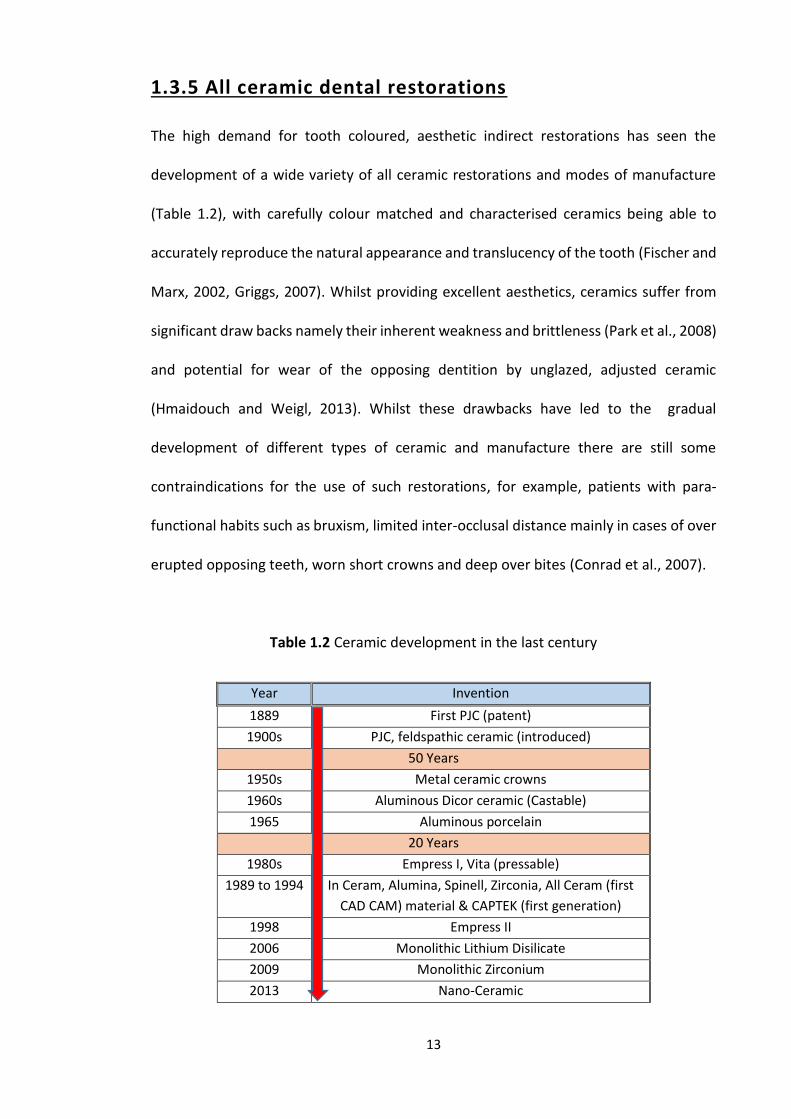
TABLE 1.2 CERAMIC DEVELOPMENT IN THE LAST CENTURY ............................................................ 13
TABLE 1.3 PORCELAIN-CLASSIFICATION AND PERFORMANCE LIMITS (ISO 6872: 2015 DENTISTRY-
CERAMIC MATERIALS) .................................................................................................... 20
TABLE 1.4 SUMMARY OF LONGEVITY STUDIES OF ZIRCONIA BASED CERAMIC RESTORATIONS ................ 34
TABLE 1.5 DEVELOPMENT TIMELINE OF CAD CAM DENTAL SYSTEMS ............................................ 37
TABLE 1.6 SHOWS DIFFERENT INTRA ORAL SCANNER AVAILABLE IN THE MARKET ............................... 45
TABLE 1.7 LIST OF CAD CAM SYSTEMS, MANUFACTURER AND TYPE OF MATERIALS USED .................. 56
TABLE 1.8 SHOWS DIFFERENT TYPES OF DENTAL CERAMICS USED WITH CAD CAM SYSTEMS ............... 57
TABLE 1.9 PREPARATION DESIGN (FINISH-LINE) FOR ALL CERAMIC CROWNS ..................................... 65
TABLE 1.10 DENTAL IMPRESSIONS, USE, ADVANTAGE, DISADVANTAGES AND GENERAL COMMENTS ...... 71
TABLE 1.11 A TIMELINE OF THE DEVELOPMENT OF DENTAL LUTING CEMENTS ................................... 78
TABLE 1.12 CEMENT CLASSIFICATION, COMMERCIAL NAMES, USE AND THEIR RECOMMENDATION ........ 80
TABLE 2.1 SHOWING THE FOUR SEGMENTS LOCATIONS FROM THE THREE UNIT ALL ZIRCONIA BRIDGE AND
THE WALLS RELATED TO EACH SEGMENT. .......................................................................... 103
TABLE 2.2 POST HOC COMPARISONS OF CEMENTATION PRESSURE/ FORCES BETWEEN PRACTITIONERS (*P
≤ 0.05; **P ≤ 0.001; THE YELLOW BOXES SHOWS NO STATISTICALLY SIGNIFICANT DIFFERENCE) 105
TABLE 3.1 DIFFERENT STUDIES INVESTIGATING THE EFFECT OF VENEERING ON INTERNAL AND MARGINAL
GAP .......................................................................................................................... 136
TABLE 4.1 DIFFERENT STUDIES ON FIT OF CAD CAM RESTORATIONS, NO. OF UNITS, CONFIGURATION
AND MEASUREMENTS ................................................................................................... 151
vi
FS = FULLY SINTERED, SS = SEMI SINTERED, NS = NO SIGNIFICANCE & SD = SIGNIFICANT DIFFERENCE
............................................................................................................................... 151
TABLE 5.1 FRACTURE BEHAVIOR OF THE ALL ZIRCONIA BRIDGES ................................................... 164
TABLE 5.2 FRACTURE BEHAVIOR OF THE ZIRCONIA FRAMEWORKS ................................................. 166
TABLE 5.3 FRACTURE BEHAVIOR OF THE VENEERED ZIRCONIA BRIDGES .......................................... 167
TABLE 5.4 STUDIES SHOWING THE RANGE OF FORCE REQUIRED TO FRACTURE ZIRCONIA BRIDGES ........ 171
TABLE 6.1 STUDIES COMPARING DIGITAL IMPRESSIONS AND CONVENTIONAL IMPRESSIONS, DIGITAL (D)
AND CONVENTIONAL (C) IN RELATION TO MARGINAL FIT. ..................................................... 190
TABLE 7.1 THE AVERAGE GOLD WEIGHT USED FOR DIFFERENT TYPES OF DENTAL RESTORATIONS (MIN AND
MAX), COLLECTED FROM DUNDEE DENTAL HOSPITAL AND SCHOOL (2010 - 2014) ................. 215
TABLE 7.2 THE DIFFERENT SIZE ZIRCONIA BLOCKS AVAILABLE, THEIR PRICES AND THE NUMBER OF UNITS OF
INDIRECT RESTORATIONS THAT CAN BE PRODUCED FROM EACH BLOCK. ................................... 216
TABLE 7.3 THE PRICES OF DENTAL RESTORATIONS MADE FROM GOLD AND ZIRCONIA........................ 217
vii
List of Figures FIGURE 1.1 THE EFFECT OF TEMPERATURE ON ZIRCONIA .............................................................. 28
FIGURE 1.2 TRANSFORMATION TOUGHENING OF ZIRCONIA ........................................................... 29
FIGURE 1.3 RESISTANCE TO CRACK PROPAGATION (COURTESY OF HTTP://WWW.BRITANNICA.COM/) ... 30
FIGURE 1.4 THE TRIANGULATION PROCEDURE IN OPTICAL SCANNERS BETWEEN THE LASER SOURCE AND
THE RECEPTOR SENSOR (COURTESY OF STEFAN PAULUS) ........................................................ 40
FIGURE 1.5 TRIANGULATION SCANNING (COURTESY OF VAN DER MEER) ......................................... 42
FIGURE 1.6 CONFOCAL LASER SCANNING (COURTESY OF VAN DER MEER) ........................................ 43
FIGURE 1.7 ACTIVE WAVE-FRONT SCANNER (COURTESY OF VAN DER MEER) .................................... 44
FIGURE 1.8 THE AXES OF A THREE (X, Y & Z), FOUR (X, Y, Z & A) AND FIVE (X, Y, Z, A & B) AXIS CAM
MILLING MACHINES ........................................................................................................ 52
FIGURE 1.9 DIAGRAM SHOWING THE WORK FLOW (CONVENTIONAL AND DIGITAL) FOR PRODUCING A
DENTAL RESTORATION USING CAD CAM TECHNOLOGY ........................................................ 59
FIGURE 1.11 COMPARISONS BETWEEN MEAN RETENTIVE STRENGTH OF DIFFERENT DEGREE OF TAPER
WITHIN EACH LUTING AGENT TESTED (ZIDAN AND FERGUSON, 2003) ...................................... 81
FIGURE 2.1 A PREPARED TEETH (UL4 AND UL6) FOR THREE UNIT ALL ZIRCONIA BRIDGES. .................. 88
FIGURE 2.1 B OCCLUSAL IMAGE SHOWING MEASUREMENT OF THE CHAMFER FINISH-LINE. ................. 88
FIGURE 2.1 C BUCCAL IMAGE SHOWING MEASUREMENT OF THE TOTAL OCCLUSAL CONVERGENCE ANGLE.
................................................................................................................................. 88
FIGURE 2.2 SCANNING SET (PHANTOM HEAD AND LAVA C.O.S) ................................................... 90
FIGURE 2.3 DIGITAL SCANNING OF TOOTH PREPARATION ............................................................. 91
FIGURE 2.4 FILLING THE ORDER FORM FOR THE BRIDGE (PRESCRIPTION) .......................................... 93
FIGURE 2.5 LAVA DESIGN CLIENT SOFTWARE BY DENTAL WINGS ................................................... 96
FIGURE 2.5 LAVA DESIGN CLIENT SOFTWARE BY DENTAL WINGS ................................................... 97
FIGURE 2.6. LOADING THE VIRTUAL BRIDGES TO THE ZIRCONIA BLOCKS ........................................... 99
viii
FIGURE 2.7 A SLA MODEL AND BRIDGE SECTION LINES .............................................................. 102
FIGURE 2.7 B MEASUREMENT OF INTERNAL FIT (CEMENT SPACE) ................................................ 102
FIGURE 2.8 FORCE FOR EACH PRACTITIONER (DOTTED LINES) AND MEAN FORCE (SOLID BLUE LINE) APPLIED
FROM THE FINAL CEMENTATION EXPERIMENT .................................................................... 106
FIGURE 3.1 ALL ZIRCONIA THREE UNIT BRIDGE AND ZIRCONIA FRAMEWORK. .................................. 120
FIGURE 3.2 (A) ZIRCONIA FRAMEWORK WITH WAXED-UP BRIDGE CONTOUR WITH SPRUES, (B) PRESSED
CERAMIC ON ZIRCONIA FRAMEWORK (BEFORE FINISHING) .................................................... 123
FIGURE 3.3 FORCE APPLICATION DEVICE FOR CEMENTATION OF THE ZIRCONIA BASED BRIDGES ........... 125
FIGURE 3.4 MEAN (AND SD) FOR INTERNAL FIT OF THREE DIFFERENT TYPES OF ZIRCONIA BRIDGES. .... 127
FIGURE 3.5 MEAN (AND SD) FOR MARGINAL FIT OF THREE TYPES OF ZIRCONIA BRIDGES. .................. 129
FIGURE 4.1 ONE OF THE FOUR UNIT BRIDGES (LEFT) AND THREE UNIT BRIDGES (RIGHT) CEMENTED ON THE
CORRESPONDING SLA MODELS ...................................................................................... 144
FIGURE 4.2 A CHART COMPARING THE INTERNAL AND MARGINAL FIT OF THE THREE AND FOUR UNIT
BRIDGES .................................................................................................................... 147
FIGURE 4.3 MAXIMUM AND MINIMUM CEMENT GAPS (µM) FOR DIFFERENT ZIRCONIA RESTORATIONS
(STUDIES IN TABLE 4.1) ................................................................................................ 153
FIGURE 5.1 METAL BASE BRIDGE HOLDER ............................................................................... 161
FIGURE 5.2 LOAD SENSOR AND LOAD APPLICATION ON BRIDGE PONTIC ......................................... 162
FIGURE 5.3 GRAPH SHOWS THE IMMEDIATE FRACTURE OF ALL ZIRCONIA BRIDGE ............................. 164
FIGURE 5.4 GRAPH SHOWS FORCE APPLICATION (N) AND IMMEDIATE FRACTURE OF ZIRCONIA
FRAMEWORK .............................................................................................................. 165
FIGURE 5.5 GRAPH SHOWS TWO STEPS FRACTURE BEHAVIOR IN VENEERED ZIRCONIA FRAMEWORKS ... 167
FIGURE 5.6 THE STRENGTH (N) OF THREE ZIRCONIA RESTORATION BRIDGES AND MAXIMUM BITE FORCE
............................................................................................................................... 174

ix
FIGURE 6.1 SILICONE IMPRESSION IN SECTIONAL METALLIC TRAY USED TO PRODUCE A TYPE IV STONE
MODEL ...................................................................................................................... 181
FIGURE 6.2 MEAN FIT (INTERNAL IN BLUE AND MARGINAL IN RED) OF THE BRIDGES MADE USING THE TWO
TYPES OF IMPRESSION TECHNIQUE (CONVENTIONAL AND DIGITAL). ....................................... 187
FIGURE 7.1 DENTIST QUESTIONNAIRE (AT PREPARATION) ........................................................... 203
FIGURE 7.2 TECHNICIAN QUESTIONNAIRE ............................................................................... 204
FIGURE 7.3 DENTIST QUESTIONNAIRE (AT FIT) ......................................................................... 206
FIGURE 7.4 PATIENT QUESTIONNAIRE .................................................................................... 207
FIGURE 7.5 QUESTIONNAIRE RESPONSE (RETURN) RATE ............................................................. 209
FIGURE 7.6 QUESTIONNAIRE 1 (N = 72, 96.0 % RESPONSE RATE) WITH DISTRIBUTION OF RESPONSES IN
RED .......................................................................................................................... 211
FIGURE 7.7 THE MEAN VALUE OF THE RESPONSES TO THE 2ND QUESTIONNAIRE QUESTIONS. .............. 212
FIGURE 7.8 THE MEAN VALUE RESPONSE RATE OF THE 3RD QUESTIONNAIRE (DENTIST AT FIT) ............ 213
FIGURE 7.9 THE RESPONSE RATE IN THE 4TH QUESTIONNAIRE (PATIENT) ........................................ 213
FIGURE 7.10 GOLD PRICES FROM 2011 TO 2015 (HTTP://GOLDPRICE.ORG/) ............................... 214
FIGURE 7.11 THE AVERAGE WEIGHT OF GOLD (MIN AND MAX) NEEDED FOR DENTAL RESTORATIONS ... 215
FIGURE 7.12 A COMPARISON OF GOLD PRICES VERSUS ZIRCONIA FOR DIFFERENT DENTAL RESTORATIONS
............................................................................................................................... 217
x
Acknowledgements I would like to express my special appreciation and thanks to my supervisors Professor
David Ricketts, and Professor Graham Chadwick. You have been a tremendous mentors
for me. I would like to thank you for encouraging my research and for allowing me to
grow as a research scientist and a clinician. Your advice on both research as well as on
my career have been priceless.
I would like to thank the staff, nurses and laboratory technicians at Dundee Dental
Hospital and School for their support throughout the course and clinical training.
I would like to thank the research subjects (my seniors, colleagues and friends) who gave
their valuable time to participate in the first laboratory experiment. I would like also to
thank 3M ESPE, and Restorative laboratory at Dundee Dental Hospital, Life Science
College and Mechanical College at the University of Dundee. All of you have been there
to support me when I needed the help while collecting the data for my Ph.D. thesis. To
my special friend, thank you very much for all the help and support.
A special thanks to my family. Words cannot express how grateful I am to my father
(Mohammed), mother (Nadia), father-in-law (Husain) and my mother–in-law (Thourya),
for all of the sacrifices that you’ve made on my behalf. Your prayer was what sustained
me thus far. I would also like to thank my brothers (Fahad, Hassan) and my sister (Lulu)
and all of my friends who supported me.
At the end words are not enough to express my appreciation to my beloved wife
(Sheima) who was always my support in the moments when there was no one to answer
my queries and for taking care of our two lovely angles (Noor and Waleed).

xi
Declaration
I, Nawaf Mohammed Almustafa, hereby declare that I am the author of this thesis and
that all the references cited have been consulted by myself. I was the principal
investigator in all studies described in this thesis. This work has not previously been
submitted for a higher degree in this or any other university.
Nawaf Mohammed Almustafa
xii
Certificate
I hereby certify that Nawaf Mohammed Almustafa has fulfilled the conditions of
Ordinance 39 of the University of Dundee and is qualified to submit this for Doctor of
Philosophy.
Professor David Ricketts
xiii
Certificate
I hereby certify that Nawaf Mohammed Almustafa has fulfilled the conditions of
Ordinance 39 of the University of Dundee and is qualified to submit this for Doctor of
Philosophy.
Professor Graham Chadwick

xiv
To my parents and my wife
Thank you very much for your support without you
this would not have been possible
MAY GOD BLESS YOU ALL
xv
Abstract
Due to the increasing demand from patients and dentists for highly aesthetic and strong,
metal-free restorations there has been a rapid increase in research into dental CAD CAM
technique and zirconia based restorations over the last decade. Such new technology
has the potential to take the place of conventional techniques and materials for
fabricating indirect dental restorations in the future.
In this PhD thesis, five laboratory studies were designed to investigate zirconia bridges
constructed using dental CAD CAM. The studies concentrated on:
1. Ideal force applied by dentists for cementing zirconia bridges and the impact on
seating.
2. The effect of firing cycles and zirconia thickness on the fit of zirconia bridges.
3. The effect of span length on the fit of three and four unit all zirconia bridges.
4. The effect of veneering on the strength of three unit zirconia bridges.
5. The fit of three unit all zirconia bridges produced by digital and conventional
techniques.
For these laboratory studies an ideal three unit (and four unit for study 3) fixed-fixed all
ceramic bridge preparation was carried out on two plastic teeth and all SLA models and
zirconia based bridges were made using the Lava COS and Lava™ CAD CAM system (3M,
ESPE).
In addition to the laboratory studies, a clinical audit was carried out to assess satisfaction
(dentist, dental technician and patient) with zirconia based restorations (through a
xvi
series of questionnaires) made and fitted at Dundee Dental Hospital and School. In
addition, as part of this audit a simple cost analysis was carried out to explore the
differences in cost between zirconia based restorations and high fusing gold alloy based
metal ceramic restorations.
Four of the studies (studies 1, 2, 3 and 5) investigated the internal and marginal fit of
the zirconia based restorations under differing laboratory and clinical procedures and
conditions. It was found that the seating force used to cement a zirconia based bridge
had no impact upon fit (Study 1). Whilst the thickness of zirconia (all-zirconia bridge and
un-veneered zirconia framework) did not affect the fit of the restoration, veneering the
framework did lead to a statistically significant deterioration in fit (Study 2). Although
leading to a poorer fit veneering did have a positive effect in strengthening the zirconia
framework, but neither un-veneered nor veneered frameworks were as strong as
monolithic/all zirconia bridges (Study 4). Despite the high shrinkage during post milling
sintering and the potential for greater distortion on longer span bridges, the longer span
bridges investigated in Study 3 did not impact upon fit. In study 1, 2, 3 and 4 the Lava
COS intra-oral scanner was used to create a digital impression of the tooth preparations
and study 5 confirmed that the fit of bridges made from these impressions were better
than those made using conventional addition cured silicone putty and wash impressions
(Study 5). The results of the questionnaires used in the audit revealed high satisfaction
rates with all stake holders and the cost analysis showed that producing zirconia based
restorations can be five to six times cheaper than conventional gold based restorations.
Despite the variations in fit which were found in Studies 2 and 5, all bridges produced
were within what would be regarded as clinically acceptable and comparable to those
produced with more traditional techniques.
1
Chapter 1
Introduction and literature Review
2
1.1 General Introduction
Since GV Black’s seminal work on Oral Pathology and restoration of teeth (Black, 1917),
great focus has been devoted to directly placed restorations, initially with amalgam
(Ramesh Bharti et al., 2010) and cohesive gold (Arthur, 1855, Arthur, 1977) and latterly
with glass ionomer (Wilson and Kent, 1971), since the acid etch technique was
discovered by Buonocore in 1955 (Buonocore, 1955), composite based restorations.
However, due to life style changes especially in younger patients, such as increased
consumption of carbonated, acidic drinks (Cheng et al., 2009) and the fact that patients
are keeping teeth for longer (Watt et al., 2013), tooth wear as well as dental caries have
become common place and a major dental problem (White et al., 2012). This has partly
led to the increased demands for indirect restorations as well as for more aesthetic
restorations. Older directly placed materials, such as dental amalgam, do not have good
aesthetics and this does not endear them to an increasingly demanding public
(Chadwick, 1988, Chadwick, 1989).
Indirect restorations, made in the laboratory, usually on stone models cast from
impressions of tooth preparations, have varied from intra-coronal inlays, onlays, partial
to full coverage crowns, and bridges to replace missing teeth (Ricketts and Bartlett,
2011). The type of restoration, its functional and aesthetic demands, will dictate which
material or combination of materials it is made of.
3
1.2 Indications for indirect dental restoration
Aesthetics, function, speech, occlusal stability, periodontal splinting, feeling of
completeness, orthodontic retention, protecting weakened teeth (as a result of caries,
endodontic treatment, trauma and tooth wear) and restoring occlusal vertical
dimension are the main reasons and indications for restoring and replacing missing
teeth with indirect restorations (Blair et al., 2002). Indirect restorations are not only
classified as to whether they are intra-coronal or extra-coronal and how much tooth
coverage occurs (full coverage crown versus three quarter crown for example) but also
by what material is used in its fabrication (all metal (noble (precious) versus base (non-
precious)), metal ceramic, all ceramic and composite).
Whilst this thesis will mainly address bridges (fixed partial prostheses/dentures), the
discussion in relation to crowns can equally apply to conventional bridge retainers and
the terms will be used interchangeably throughout.
1.3 Dental materials used for indirect dental restoration
1.3.1 All metal indirect restorations
Full crowns in metal are widely used in the posterior region as aesthetic demands are
less and they require minimal tooth preparation which makes them a less destructive
restoration choice compared to those made from other materials (all ceramics and
composite) or combination of materials (metal ceramic) (Blair et al., 2002); this is largely
due to the strength of the metals in thinner sections. Some of the major characteristics
of most metals and alloys are that they are hard, ductile and good conductors of both
heat and electricity. However material selection for all metal dental restorations will
4
depend on many factors such as cost, corrosion and tarnish, castability and handling,
physical properties, biocompatibility and the ability to resin bonding (Wassell et al.,
2002c).
Noble (precious) versus base (non-precious) metals
The metal elements used in indirect dental restorations can be divided into noble or
precious metals (e.g. gold, platinum, palladium, rhodium, ruthenium, iridium and
osmium), and base or non-precious metals (e.g. nickel, chrome and cobalt). Noble
metals are elements which are very resistant to corrosion, unlike the base or non-
precious elements which are susceptible to oxidisation (corrosion) in moist
environments.
Gold is one of the oldest materials used to directly fill tooth cavities, because pure gold
is soft and malleable, making it easy to form and shape by cold working with gold foil
(Liviu Steier et al., 2007). However, today gold is rarely used in dentistry as a pure metal
(Knosp et al., 2003) as its properties make it unsuitable for casting into indirect
restorations as it has a low proof stress (the load per unit area that a structure can
withstand without being permanently deformed by more than a specific amount (0.2 %
(30 MPa)) and a large elongation (the length at breaking point expressed as a percentage
of its original length (i.e. length at rest) (45.0 %)) (Knosp et al., 2003). To overcome these
problems other elements are added to gold in varying quantities to give a range of gold
alloys with slightly different properties making them suitable for various clinical
applications. Such improvements in properties arise from changes in the basic crystal
lattice of the alloy as a consequence of the inclusion of other elements.
5
Alloys used in dentistry are a mixture of two or more metallic elements and are classified
according to the percentage of the major elements they contain (gold, palladium, silver,
nickel, cobalt, chrome or titanium) (Anusavice et al., 2012) as well as their intended
clinical application (ISO Standard 8891:2000).
Nobel (precious) metal alloys
Noble metal alloys consist of more than 75.0 % of the noble elements in their
composition (Anusavice et al., 2012). They are often called precious metal alloys because
the noble elements are expensive and this can cause some confusion in dental
terminology.
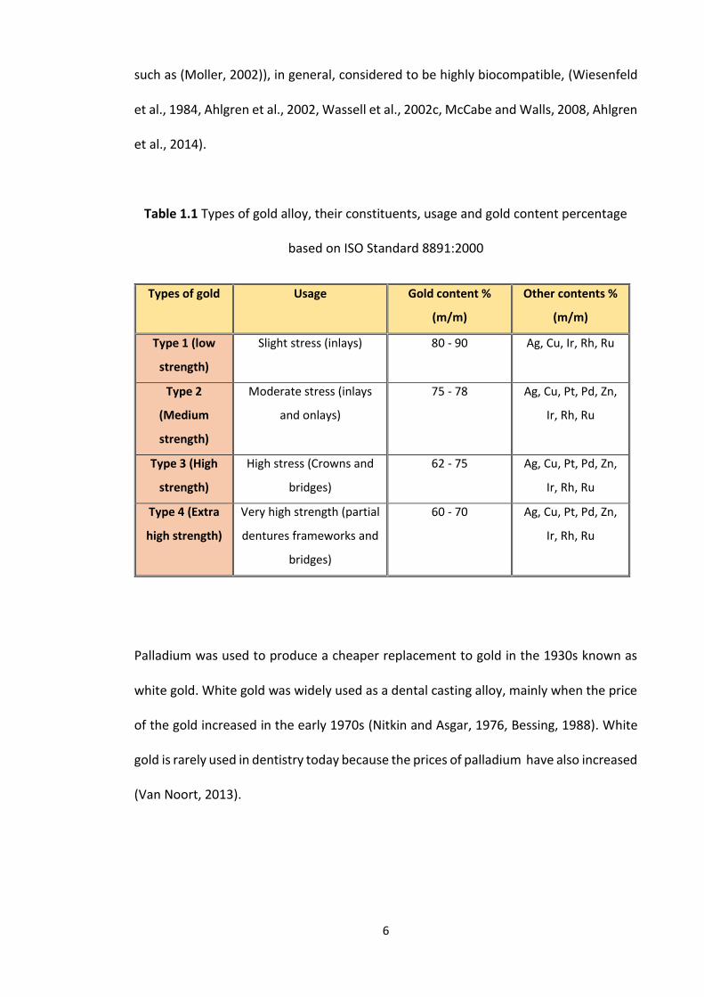
Today four types of gold casting alloys exist, (low strength, medium strength, high
strength and extra high strength) which are classified according to the percentage
content of noble metals (Table 1.1) (ISO Standard 8891:2000). The percentage of gold
drops when moving from type 1 (soft) to type 4 (extra high strength), leading to an
increase in hardness, proportional limit and strength, but with a concomitant decrease
in ductility and corrosion resistance (Knosp et al., 2003, McCabe and Walls, 2008). Noble
metal alloys can be cast into relatively thin sections of 0.3 to 0.5 mm (Shillingburg, 1997),
and can achieve a high degree of casting accuracy and hence fit and longevity. As such
this has made noble metal alloys the “gold standard” restoration historically against
which newer materials and modes of manufacture are compared.
In addition to the afore mentioned properties, as dental materials are in contact with
the oral tissues for many years, it is important to choose alloys with minimum biological
risk This means that the materials should have low release of elements (corrosion),
which can be achieved by using noble metal alloys (Wataha, 2000). Gold alloys are
(disregarding the few studies reporting allergic reaction to gold and palladium alloys
6
such as (Moller, 2002)), in general, considered to be highly biocompatible, (Wiesenfeld
et al., 1984, Ahlgren et al., 2002, Wassell et al., 2002c, McCabe and Walls, 2008, Ahlgren
et al., 2014).
Table 1.1 Types of gold alloy, their constituents, usage and gold content percentage
based on ISO Standard 8891:2000
Types of gold Usage Gold content %
(m/m)
Other contents %
(m/m)
Type 1 (low
strength)
Slight stress (inlays) 80 - 90 Ag, Cu, Ir, Rh, Ru
Type 2
(Medium
strength)
Moderate stress (inlays
and onlays)
75 - 78 Ag, Cu, Pt, Pd, Zn,
Ir, Rh, Ru
Type 3 (High
strength)
High stress (Crowns and
bridges)
62 - 75 Ag, Cu, Pt, Pd, Zn,
Ir, Rh, Ru
Type 4 (Extra
high strength)
Very high strength (partial
dentures frameworks and
bridges)
60 - 70 Ag, Cu, Pt, Pd, Zn,
Ir, Rh, Ru
Palladium was used to produce a cheaper replacement to gold in the 1930s known as
white gold. White gold was widely used as a dental casting alloy, mainly when the price
of the gold increased in the early 1970s (Nitkin and Asgar, 1976, Bessing, 1988). White
gold is rarely used in dentistry today because the prices of palladium have also increased
(Van Noort, 2013).
7
Base metal alloys (non-precious)
Base metals alloys contain a very low percentage (≤ 25.0 %) of noble or non-noble metals
in their composition (Anusavice et al., 2012). There are three groups of base metal alloys
depending on the materials used, namely cobalt chrome (Co/Cr), nickel chrome (Ni/Cr)
and titanium. Cobalt chrome consists mainly of cobalt (35.0 – 65.0 %), chromium (25.0 -
35.0 %) and molybdenum (4.0 %) whilst nickel chrome mainly consists of nickel (61.0 –
81.0 %), chromium (20.0 %), molybdenum (4.0 %) and beryllium (4.0 %). Both types of
base metal alloy (Co/Cr and Ni/Cr) contain smaller amounts of other materials such as
silicone and carbon which contribute to the mechanical and physical properties of the
alloys (improved casting, handling, ductility, hardness and strength) (Anusavice et al.,
2012). Because of their increased strength base metal alloys can be cast to a thickness
as low as 0.2 mm (Shillingburg, 1997) with satisfactory long term clinical function.
Base metal alloys are widely used for metal ceramic restorations and can be used for all
metal dental restorations, however, some of the constituents are considered to be toxic
and/or can cause allergic reactions in some patients. The main known allergic reaction
is caused by nickel which can lead to contact dermatitis. To overcome this nickel free
base metal alloys are available and have been used widely (Magnusson et al., 1982,
Hildebrand et al., 1989, Staerkjaer and Menne, 1990, Wassell et al., 2002c, McCabe and
Walls, 2008).
Titanium is well known for its biocompatibility. However, casting titanium requires high
temperatures and special investment and consequently it is not commonly used for
customised bespoke dental restorations (Ida et al., 1982). Therefore its use is mainly
limited to pre-formed post, crowns, frameworks and dental implants (Kikuchi and
Okuno, 2004). Whilst titanium has been used to create metal based indirect dental
8
restorations using a spark erosion technique, studies are few and its use has not taken
off commercially (Nakaoka et al., 2011, Özcan and Hämmerle, 2012).
1.3.2 Metal ceramic crowns
Metal ceramic crowns/bridge retainers are the most commonly used type of crown or
retainer, because they combine both the strength of the metal framework and the
aesthetics of the veneering ceramic (Ku et al., 2002, Zarone et al., 2011).
When it comes to choosing a metal alloy for the core (coping) of the metal ceramic
restoration, its coefficient of thermal expansion is very important, because if there is a
large mismatch between the metal alloy and the veneering ceramic, expansion and
contraction on heating and cooling will result in stress generation within the ceramic
and crack formation leading to catastrophic fracture of the ceramic (Combe et al., 1999,
McCabe and Walls, 2008, Bonsor and Pearson, 2013). The melting temperature of the
metal alloy is also important, because if it is too close to the firing temperature of the
ceramic, melting of thin sections of the coping or deformation can occur. Most of the
metal alloys available for all metal dental restorations can be used when constructing
metal ceramic dental restorations as even the majority of noble metal alloys have a high
fusing (melting) point as compared to the firing temperature of the ceramic (Combe et
al., 1999, McCabe and Walls, 2008, Van Noort, 2013).
To ensure optimum aesthetics when making a metal ceramic crown, an opaque ceramic
is needed to mask the metallic appearance of the coping beneath the veneering ceramic
(Combe et al., 1999, McCabe and Walls, 2008, Bonsor and Pearson, 2013). However, to
allow for the thickness of the metal alloy coping, the opaque ceramic and the veneering
ceramic, the tooth has to undergo a heavier preparation, than that required for all metal
9
restorations, in the order of around 1.5 to 2 mm where metal and ceramic coverage is
required (Blair et al., 2002).
1.3.3 Veneering Ceramics and its techniques
Constructing a dental ceramic restoration in the laboratory is time consuming and
requires high skills to achieve satisfactory results with respect to strength and
aesthetics. After constructing the coping or framework whether in metal or some form
of ceramic, a veneering ceramic layer should be applied over it, which is mainly
responsible for aesthetics; the core or framework confers strength upon the restoration.
There are two methods for veneering frameworks or copings, these are the layering and
the pressing techniques (Miyazaki et al., 2013).
Layering technique
The layering technique (conventional/ traditional) is considered to be the most
commonly used veneering technique, for restorations within the aesthetic zone or smile
line. This technique gives greater control over the aesthetics of the restoration where
dentine and enamel shades can be built up incrementally to mimic natural tooth tissues.
First, the frame work or coping is covered by an opaque ceramic to mask the dark shine
through of metal (if metal ceramic restoration) or coloured to form an appropriate base
colour (if zirconia at its pre-sintered stage). If masking a metal framework the opaque
layer is either left to dry or placed in a furnace to speed up the drying process
(Schweitzer et al., 2005).
10
Following this, the selected shades of veneering ceramic are built-up by hand. The
dentine and enamel ceramics (feldspathic ceramic) consist of a powder which is mixed
with distilled water to form a creamy paste. The dentine shade is applied first using a
vibration technique to allow the powder to settle with no voids and using absorbent
paper to remove excess water. The consolidated powder can then be carved to the
shape of the dentine, incorporating anatomical features such as mamelons and then the
enamel ceramic can be added in a similar fashion. The ceramic build-up is made larger
than the desired final restoration in order to allow for shrinkage (10.0 to 20.0 %) caused
by condensation and the firing/sintering procedures. Until the ceramic is sintered the
powder liquid mass is still fragile and should be handled with care (Bonsor and Pearson,
2013).
Following sintering in the furnace, the ceramic crown contour can be adjusted and
before glazing, stains can be used to produce a more detailed final restoration, marking
up stained pits and fissures, lamellae or hypoplastic spots for example. Finally, a glaze
layer is applied in order to produce a smooth shiny surface to the restoration. For this
purpose, a low fusing transparent glass ceramic is painted in thin layers on the outer
surface of the dental restoration which is then returned to the furnace to produce the
glaze (Griggs, 2007, Bonsor and Pearson, 2013).
Pressing technique
The pressing technique uses the lost wax approach similar to that used in casting metal
restorations. First, the metal frame work with opaque ceramic (Schweitzer et al., 2005)
or the coloured zirconia framework undergoes a wax additive process to contour the
final restoration. This is then sprued and invested in a refractory investment, which,
once set, is placed in a furnace to allow burnout of the wax leaving a space for the
11
ceramic to fill. A mono-colour leucite ceramic ingot is then melted/softened at high
temperature (around 1000° - 1180° C) in a furnace and then slow pressure is applied via
a plunger in order to press the ingot into the void created after de-waxing the
framework. Once removed from the furnace and cooled the investment is then
sectioned and the restoration carefully removed, cleaned, coloured and
glazed/polished.
The pressing ceramic is not translucent and only few shades are available which makes
it difficult to produce a highly aesthetic dental restoration using this technique.
However, once the pressing procedure is finished, the buccal pressed ceramic can be cut
back and a conventional feldspathic ceramic can be used to produce a better aesthetic
(shade and translucency) dental restoration (Griggs, 2007, Chadwick and Hall, 2011,
Bonsor and Pearson, 2013).
1.3.4 Bonding ceramics to metal alloys
Bonding ceramics to metal alloys relies on an intimate contact between the ceramic and
the metal alloy coping. This can be achieved by one of three mechanisms:
Mechanical retention: this occurs usually as the ceramic flows into the micro-spaces
created in the surface of the metal alloy during the fabrication process. In addition, air
abrasion using alumina (25.0 – 30.0 µm) and/or grinding can increase the surface
roughness to maximise the mechanical interlocking (Chadwick and Hall, 2011, Bonsor
and Pearson, 2013, Van Noort, 2013).

12
Compression fit: this technique depends mainly on the difference in the coefficient of
thermal expansion between the two materials (the metal alloy and the veneering
ceramic). As most ceramics have a coefficient of thermal expansion that is lower than
the metal alloys, the metal alloy will contract more than the ceramic on cooling and as
a result the ceramic will be placed under compression. The shrinkage of the ceramic will
also enable adaptation to the irregularities within the metal surface. The coefficient of
thermal expansion of the metal alloy and the veneering ceramic should however be
similar or near to each other to avoid undue stress within the ceramic (Chadwick and
Hall, 2011, Bonsor and Pearson, 2013, Van Noort, 2013).
Chemical bonding: In order for a chemical bond to be achieved, an oxide layer is
required. The oxide layer formed on the metal surface then chemically bonds to the
oxide layer formed on the opposing ceramic. Compatibility of the metal and ceramic is
a must for this bond to happen. The elements that can be used to form oxides include
gallium, indium, zinc and tin, as well as the base metals which have been widely used
for this purpose because they produce thick oxide layers. In the case of noble metal
alloys, the coping or framework is returned to the furnace at a specific temperature and
a partial vacuum to allow an oxide layer to be formed via the elements mentioned which
are added to the alloy. The oxidising process needs to be precise because the cohesive
bond between the oxide layer and the ceramic might fail if the oxide layer is too thick
(Bonsor and Pearson, 2013, Van Noort, 2013).
13
1.3.5 All ceramic dental restorations
The high demand for tooth coloured, aesthetic indirect restorations has seen the
development of a wide variety of all ceramic restorations and modes of manufacture
(Table 1.2), with carefully colour matched and characterised ceramics being able to
accurately reproduce the natural appearance and translucency of the tooth (Fischer and
Marx, 2002, Griggs, 2007). Whilst providing excellent aesthetics, ceramics suffer from
significant draw backs namely their inherent weakness and brittleness (Park et al., 2008)
and potential for wear of the opposing dentition by unglazed, adjusted ceramic
(Hmaidouch and Weigl, 2013). Whilst these drawbacks have led to the gradual
development of different types of ceramic and manufacture there are still some
contraindications for the use of such restorations, for example, patients with para-
functional habits such as bruxism, limited inter-occlusal distance mainly in cases of over
erupted opposing teeth, worn short crowns and deep over bites (Conrad et al., 2007).
Table 1.2 Ceramic development in the last century
Year Invention
1889 First PJC (patent)
1900s PJC, feldspathic ceramic (introduced)
50 Years
1950s Metal ceramic crowns
1960s Aluminous Dicor ceramic (Castable)
1965 Aluminous porcelain
20 Years
1980s Empress I, Vita (pressable)
1989 to 1994 In Ceram, Alumina, Spinell, Zirconia, All Ceram (first
CAD CAM) material & CAPTEK (first generation)
1998 Empress II
2006 Monolithic Lithium Disilicate
2009 Monolithic Zirconium
2013 Nano-Ceramic
14
Porcelain jacket crowns (PJC)
Porcelain Jacket Crowns are one of the oldest all ceramic crowns, that were introduced
before bonding ceramics to tooth structure was possible. However their use was
restricted mainly to the anterior teeth due to the relatively poor physical properties of
porcelains at the time (Magne et al., 2010, Chadwick and Hall, 2011). These crowns were
made of feldspathic ceramics, and whilst highly aesthetic, they were very fragile and
prone to fracture. Feldspathic ceramic is composed mainly of oxide components (SiO₂,
Al₂O, and Na₂O). Potassium and sodium feldspars are naturally occurring elements
composed mainly of potash (K₂O), soda (Na₂O) and alumina (Al₂O). A glass phase is
formed when potassium feldspar is fired to high temperatures and the material
undergoes expansion. Leucite, which has a high coefficient of thermal expansion, is
added to control the thermal expansion (Van Noort, 2013).
In order to overcome the low material strength, the ceramic in practical use had to reach
a thickness of 1.5 to 2 mm, and as a result the tooth preparation was relatively excessive
(Blair et al., 2002, Ricketts and Bartlett, 2011) in order to accommodate this.
Traditionally, the die of the prepared tooth (for PJC) was covered with a burnished
platinum foil, the purpose of which was mainly a supporting matrix for the ceramics
while building-up the PJC and during the firing process (Bonsor and Pearson, 2013). The
platinum foil was then removed from the fit surface before cementing the dental
restoration with a non-adhesive luting cement, typically a zinc phosphate (Yu et al.,
2014).

15
Due to the inherent weakness of the PJCs a twin (platinum) foil technique was
introduced. The first platinum foil served the same purpose as the one platinum foil
technique and was removed following firing, however a second platinum foil which was
laid down over the first was left in place to support the ceramic restoration, acting as a
core and increasing the strength while cemented in the mouth (McLean et al., 1976,
Moffa, 1988).
A number of foil techniques followed on from platinum foil and work carried out by
McLean and Sced in 1987, showed that to resist ceramic fracture a minimum foil
thickness of 0.1 mm should be reached (McLean and Sced, 1987).
Alumina
In an attempt to further increase the strength of PJCs, in 1965 McLean introduced
aluminous porcelain to dentistry (McLean and Hughes, 1965). Aluminous porcelain had
a higher strength compared with feldspathic porcelain and was used as a coping material
onto which feldspathic porcelain could be added. Because of the higher strength of the
aluminous porcelain, crack propagation from any micro cracks formed in the more
superficial feldspathic porcelain is prevented. Originally alumina was added to
feldspathic porcelain but due to its opacity could only be added up to 45.0 – 50.0 %
before it affected the overall appearance of the crown (McLean, 1997). The fired
alumina core and aesthetic feldspathic porcelain veneer became the standard to
produce PJCs, but despite the increase in flexural strength it was not recommended for
posterior teeth (Wassell et al., 2002c).
16
Dentine bonded crowns
Whilst developments in relation to strengthening ceramics, but maintaining their
aesthetics continue, in the early to mid-1990’s the dentine bonded crown was described
which achieved its strength from being bonded to the entire underlying tooth structure
or composite core (Burke, 1996). In this way any micro cracks that occur in the ceramic
are prevented from propagating leading to catastrophic failure (Burke, 1995). This is
because such cracks propagate from within the crown outwards to the surface
(Chadwick and Hall, 2011). The dentine bonded crown developed from the adhesive
technology which was used to cement ceramic veneers. Such crowns consist of a
ceramic whose fit surface can be etched with hydrofluoric acid to create a
micromechanically retentive surface. Bonding to the ceramic is also facilitated through
application of a silane coupling agent. The luting cement used to fit the crown is a dual
cured composite resin luting cement which is bonded to the tooth via a compatible
dentine bonding agent (Burke, 2007).
1.4 Ceramics
Keramos is the Greek word and origin of the word Ceramic which means ‘potter’s clay
or burnt stuff’. Ceramics are man-made materials which are the result of mixing and
“burning” together different metallic and non-metallic elements (McCabe and Walls,
2008, McLaren and Cao, 2009). Oxygen unions with metals or semi-metal elements,
usually aluminium, calcium, magnesium, sodium, zirconium and silicone, produce metal
oxides that are the main components of ceramics (McCabe and Walls, 2008). The terms
ceramic and porcelain are often used interchangeably, however, ceramic is the overall
term given to the main group of materials of which porcelain is a specific example
17
containing Kaolin, Quartz and Feldspar (Ferracane, 2001). To use the term dental
porcelain would therefore be inappropriate because the dental ceramics contain no or
little kaolin (Bonsor and Pearson, 2013).
Ceramics have been used in dentistry for more than 200 years, the first being introduced
to dentistry by a French dentist called De Chemant in 1789 (Miyazaki and Hotta, 2011).
In 1808 an Italian dentist Fonzi invented “terrametallic incorruptibles” ceramic teeth,
which were held in situ using platinum pins or frames. By 1903 Dr. Charles Land
presented the first dental ceramic crown and, in 1963, the first commercially available
dental ceramic was introduced by VITA Zahnfabrik (Kelly et al., 1996, C. Â. M. Volpato et
al., 2010, R. Narasimha Raghavan, 2012).
1.4.1 Dental ceramic composition
Ceramic on its own is weak, opaque and porous, which makes it unsuitable for dental
applications (McCabe and Walls, 2008), because dental restorations made out of pure
ceramic are easy to fracture as a result of cracks developing during the fabrication
process in the laboratory (McLean, 2001). Different types of minerals (quartz, silica (flint)
and feldspar (potassium-aluminium silicate)) are therefore blended together to produce
stronger and more translucent materials for dental use (McCabe and Walls, 2008).
Dental ceramics can be used for different purposes and depending upon their
application, clay (kaolin), silica, binder (feldspar) and glasses can be blended in different
ratios to produce high-fusing and low-fusing dental ceramics (Ferrancane, 1995, Combe
et al., 1999, McCabe and Walls, 2008).
18
1.4.2 Ceramic properties
Ceramics found their way into dentistry and were considered a material of choice due
to their low cost and ready availability as well as:
1. Biocompatibility
2. Abrasion resistance
3. Stain resistance
4. Stable colour
5. White in colour and can be pigmented to match any dental shade
Despite these ideal properties ceramics, suffer from inherent brittleness and much
work has been done to overcome this, such as building up the restoration on thin
metal copings or alumina cores mentioned previously in Section 1.3.5 in order to
prevent crack propagation. The next section further explores the different types of
ceramics that have been developed for dental use.
1.4.3 Classification of dental ceramics
Today, many types of dental ceramics are commercially available, with each ceramic
having different physical properties, clinical use and production method. As a result they
have been classified in different ways in the literature. Some publications classify dental
ceramics according to the type of ceramic (feldspathic, aluminous, glass infiltrated
aluminous, glass infiltrated spinel and glass ceramics) (McLean, 2001), firing (fusing)
temperature (High > 1300° C, medium 1101° - 1300° C, low 850° - 1101° C, ultralow <
850° C) (Anusavice et al., 2012), substructure material (glass ceramic, CAD CAM ceramic,
sintered ceramic core) (Kelly et al., 1996) and fabrication technique (castable ceramics,
19
pressable ceramics and machinable ceramics (CAD CAM)) (Qualtrough and Piddock,
2002). A recently updated International Standard (ISO 6872: 2015 Dentistry – ceramic
Materials) classifies them according to cementation, minimum mean flexural strength
and chemical solubility (Table 1.3).
For the purpose of this thesis the different types of ceramic will be classified according
to fabrication technique as this fits with the work undertaken in this thesis.

20
Table 1.3 Porcelain-classification and performance limits (ISO 6872: 2015 Dentistry- Ceramic Materials)
Class Recommended clinical indications Cementation (A = Adhesive,
N = not adhesive)
Minimum mean flexural
strength (MPa)
Chemical Solubility
(µg/cm²)
1a Monolithic single unit anterior crowns, veneers,
inlays and onlays.
A < 50 < 100
1b Coverage of ceramic or metal framework A < 50 < 100
2a Monolithic ceramic for single unit anterior/
posterior restorations.
Fully covered substructure ceramic for single unit
anterior/ posterior prostheses
A > 100 < 100
2b Fully covered substructure ceramic for single
anterior/posterior prostheses
A > 100 < 2000
3a Monolithic ceramic for single-unit
anterior/posterior prostheses and for 3 unit
prostheses not involving molars
A/N > 300 < 100
3b Fully covered substructure for single-unit
anterior/posterior prostheses and for 3 unit
prostheses not involving molars
A/N < 2000
4a Monolithic ceramic for 3 unit prostheses with
molars
A/N > 100 < 100
4b Fully covered substructure for 3 unit prostheses
with molars
A/N < 2000
5 Monolithic ceramic for prostheses involving 4 or
more units or fully covered substructure for
prostheses involving 4 or more units
A/N > 800 < 100
21
Powder/liquid ceramics
Conventional ceramics are presented in a powder/liquid form and include glass
ceramics and glass/crystal ceramics which are often used as veneering ceramics for all
ceramic and metal frameworks. Feldspathic and alumina ceramics are examples of
powder liquid ceramics which have been discussed in section 1.3.5.
Whilst Section 1.3.5 describes the conventional use of an alumina core made from a
powder liquid build up, a newer technique called slip casting has also been used to
produce an alumina strengthened coping, the original In-Ceram (Vita Zahnfabrik). Its use
in dentistry was described in 1989 by Sadoun (McLean, 2001). The terminology slip
casting should not be confused with the casting method traditionally employed in the
lost wax technique; it more accurately describes a powder/liquid technique.
In-Ceram Alumina® (Vita Zahnfabrik) ceramic consists mainly of a partially sintered
alumina interconnecting framework infused with lanthanum glass. In this process, the
alumina particles are mixed with water to produce a “slip” which is painted over an
absorbent gypsum die of the prepared tooth. The water from the slip is then absorbed
by the gypsum die due to capillary action, condensing the alumina particles against the
die. The alumina particles are then partially sintered together to form an
interconnecting mesh into which lanthanum is infused, producing a dense coping with
good physical properties onto which veneering ceramic can be built (Kelly et al., 1996,
McLean, 2001).
A further modification of the powder/liquid technique has been used to generate high
alumina reinforced crowns or Procera All-Ceram (Procera-Sandvik, Stockholm, Sweden).
In this technique high-purity alumina particles are dry pressed over an over-sized die of
the prepared tooth. The oversized die is manufactured by scanning a conventional stone
model of the tooth preparation, the data obtained being sent electronically to a dental
22
laboratory in Sweden where an enlarged copy die is milled; the enlargement being
carefully calculated based upon the sintering shrinkage of the material. The compacted
and now unsupported alumina core is then sintered at 1550° C for one hour (McLean,
2001). The high alumina coping produced is then returned to the referring laboratory
for veneering with aesthetic ceramic (Qualtrough and Piddock, 2002).
This section has explored how conventional alumina cores, All-Ceram and In-Ceram slip
casting have been used to produce modified alumina cores of increased strength (Neiva
et al., 1998) and in some cases used for bridges as well as single unit crowns (Kelly et al.,
1995, McLaren, 1998).
Castable ceramics
Dicor (Dentsply International & CORning glass (DENTSPLY International Inc, York, Pa.))
which consists of tetrasilicic fluormica crystals, was the first commercially available
castable ceramic that could be used to manufacture indirect restorations using the lost
wax technique (Adair and Grossman, 1984, Grossman, 1985, Malament and Socransky,
1999). This crystal structure imparted strength and fracture resistance to the restoration
by virtue of their flexibility and plate like form which could interfere with crack
propagation (McLean, 2001). Because Dicor restorations are monochromatic, their
shade and characterisation had to be achieved with surface colourant glass of
approximately 50.0 to 100.0 µm thickness (Kelly et al., 1996). However, this wore down
over time with concomitant deterioration in the aesthetics. To overcome this, for
restorations in the smile line, the Dicor crowns were often cut back to allow for a
veneering feldspathic ceramic with the resultant restoration being called a Willi’s glass
crown (Geller and Kwiatkowski, 1987).
23
Despite claims of increased strength, Dicor was still considered to be relatively weak and
its use was recommended for inlays only (McLean, 2001). However, in a study of 1444
Dicor restorations, Malament and Socransky (1999) showed that after 16 years, the
survival of the restorations could be improved by acid etching the fit surface of the
restoration and bonding the crowns down to prepared dentine with resin luting cement.
At 14 years the same authors estimated that the survival rate of Dicor etched
restorations was between 71.0 to 75.0 %, with tooth position being the greatest
influencing factor; highest failure rates in second molar teeth and lowest on incisor teeth
(Malament and Socransky, 1999). Earlier laboratory work on dentine bonded crowns
also showed that Dicor crowns were significantly stronger under compressive loading
compared with either feldspathic or aluminous ceramic dentine bonded crowns (Mak et
al., 1997).
Pressable ceramics
One of the main disadvantages in the manufacture of conventional ceramic restorations
is the high degree of shrinkage on firing. Pressable ceramics overcome this to a degree
and are presented as glass ceramic ingots which are similar in composition to
powder/liquid ceramics. However; they contain less porosity and are more crystalline in
content. In this technique, the ceramic ingots are heated to a specific temperature
where they start melting and become a viscous liquid, after which they are forced under
pressure to fill a cavity in a refractory mould (lost wax technique) (Bonsor and Pearson,
2013). The shrinkage that occurs when the crown has formed is mainly due to
contraction on cooling which is readily overcome/counteracted by the expansion of the
investment material (Kelly et al., 1996). Full details of the pressing process are described
24
in chapter 3 (2nd laboratory study) as this technique is used in the work presented in this
thesis.
IPS-Empress® and IPS-Empress®2 ceramics are examples of pressable ceramics. They
consist of leucite-reinforced and lithium disilicate reinforced glass ceramics respectively.
The leucite and lithium disilicate reinforces the glassy matrix and aids in preventing crack
propagation. The melting point of IPS-Empress® is 1180° C and that of IPS-Empress® 2 is
920° C. SEM analysis of the two materials show that the leucite crystal content of IPS-
Empress® is higher than the lithium disilicate content in IPS-Empress®2 (70.0 % and 35.0
% volume respectively) with the latter having more elongated and interlocking crystals.
It is these structural differences which result in the IPS-Empress® 2 having superior
mechanical properties; its flexural strength for example is three times that of IPS-
Empress® (Holand et al., 2000).
Because the IPS Empress ingots are monochromatic, the coping formed needs to be
veneered with aesthetic ceramics to produce a more detailed final indirect dental
restoration (McLean, 2001, Qualtrough and Piddock, 2002). Both types of Empress can
be readily etched for use as dentine bonded crowns.
IPS-Empress® ceramics is now called IPS E max®, where lithium oxide is added to the
alumina-silicate glass, It delivers outstanding aesthetics, precision fit and strength
(Shenoy and Shenoy, 2010).
25
Machined processed crystalline systems
More recently, Computer Aided Design Computer Aided Manufacturing (CAD CAM)
technology has been introduced to dentistry and has become a practical fabrication
option for indirect dental restorations. This technology was first introduced for milling
fully sintered ceramic blocks, however, its use has now been expanded and can be used
to mill semi-sintered ceramics which subsequently undergo heat treatment to ensure
full sintering (Denry and Holloway, 2010). CAD CAM technology consist of three stages;
first the scanning (in the laboratory or intra-orally), 3D designing (CAD) via computer
software and, finally, milling of the dental restoration (CAM). As a result of using CAD
CAM technology, designing and fabrication of dental restorations can be completed
within hours, which allows the patient to receive their dental restoration the same day
(one appointment dental restoration). Consequently, a new class of ceramics was
developed for use with CAD CAM systems, namely machinable glass-ceramics. Examples
of ceramic materials available for the CAD CAM technology are: Silica based ceramics,
infiltration ceramics and oxide high performance ceramics (Beuer et al., 2008c).
Silica based ceramics
There are several types of Silica based ceramic blocks available for the construction of
dental restorations using CAD CAM technology (Vitablocs Mark II (Vita), IPS e.max CAD
(Ivoclar Vivadent), Vitablocs TriLuxe (Vita) and IPS Empress CAD Multi (Ivoclar
Vivadent)). Besides the availability of monochromatic ceramic blocks, multi-coloured
layered ceramic blocks are also provided by some manufacturers (e.g. IPS Empress CAD
Multi (Ivoclar Vivadent)), the latter being used mainly when fabricating fully contoured
anatomical crowns in the smile line (McCabe and Walls, 2008).
26
Infiltrated ceramics
An example of an Infiltrated ceramic blocks that can be used for CAD CAM systems is
Vita In-Ceram, which has the same composition as the conventional In-Ceram ceramics
(Beuer et al., 2008c). Vita has produced three types of ceramics that can be used with
CAD CAM technology:
In-Ceram Alumina VITA, this ceramic is based on the original powder/liquid material
that was described in Section 1.3.5. Since 1999, condensed partially sintered blocks of
this material have become available for milling (Tinschert et al., 2001a, Apholt et al.,
2001, Chaar et al., 2015). Its use is suitable for anterior and posterior crown copings and
anterior three unit bridges (Vult von Steyern et al., 2001, Beuer et al., 2008c).
In-Ceram Zirconia (Vita) ceramic was initially developed as a powder/liquid ceramic in
the same way as In-Ceram alumina, however, partially stabilised zirconium oxide (35.0
%) was added to the original In-Ceram alumina powder producing a porous partially
sintered framework into which glass can infiltrate. Partially sintered blocks of this
material, suitable for milling, have also been available since 1999 (Apholt et al., 2001,
Tinschert et al., 2001a, Chaar et al., 2015). The addition of the zirconium oxide led to an
increase in the flexural strength of the material enabling it to be used in the manufacture
of three unit bridges as well as single unit restorations (Wagner and Chu, 1996, Chong
et al., 2002, Guazzato et al., 2002, Raigrodski, 2004, Yilmaz et al., 2007, Miyazaki et al.,
2013, Chaar et al., 2015).
In-Ceram Spinell (Vita), this material again is based upon the In-Ceram alumina
however, in this material, magnesia is added to the alumina coping material which
subsequently undergoes glass infiltration (Conrad et al., 2007). The addition of the
27
magnesia makes the In-Ceram Spinell much more translucent (Heffernan et al., 2002a,
Heffernan et al., 2002b), so unlike the In-Ceram alumina and zirconia it is not suitable
for use over discoloured teeth. Whilst the flexural strength of In-Ceram Spinell is not as
good as that of In-Ceram alumina or zirconia (Magne and Belser, 1997, Chaar et al.,
2015) its translucency makes it ideal for use in highly aesthetic single unit anterior crown
copings on vital teeth and in young patients (Beuer et al., 2008c).
Oxide high performance ceramics
Oxide high performance ceramic blocks suitable for milling in the CAD CAM process
include aluminium oxide (e.g. In-Ceram AL Block (VITA)) and zirconium oxide (e.g. Lava
Frame (3M ESPE), Everest ZS und ZH (KaVo), In-Ceram YZ (VITA)). These materials offer
restorations of superior strength (flexural strength and fracture toughness) compared
to other all ceramic restorations. Aluminium oxide blocks have been recommended for
use as copings for anterior and posterior crowns and bridges in the anterior region
(Beuer et al., 2008c) and due to the superior physical properties of the zirconium oxide
blocks can also be used for bridges and implant abutments both in the anterior and
posterior region (Komine et al., 2010).
1.5 Zirconium
Zirconium dioxide (ZrO₂), is a new material that has become popular over the last
decade, as an aesthetic ceramic that can be used to replace metal alloys when
constructing indirect dental restorations (copings and frameworks). In addition to
aesthetics, zirconia has superior mechanical properties, mainly its high flexural strength
and fracture toughness (Denry and Kelly, 2008). Zirconium dioxide ceramic is also
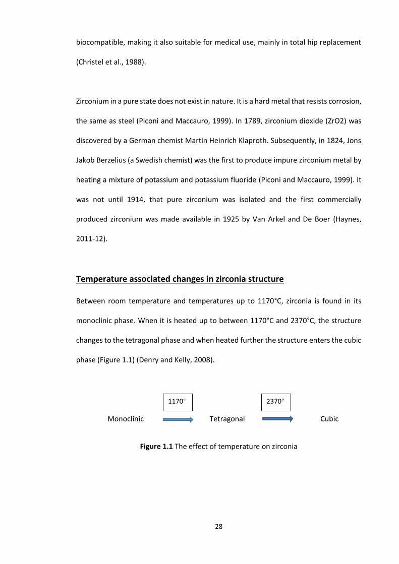
28
biocompatible, making it also suitable for medical use, mainly in total hip replacement
(Christel et al., 1988).
Zirconium in a pure state does not exist in nature. It is a hard metal that resists corrosion,
the same as steel (Piconi and Maccauro, 1999). In 1789, zirconium dioxide (ZrO2) was
discovered by a German chemist Martin Heinrich Klaproth. Subsequently, in 1824, Jons
Jakob Berzelius (a Swedish chemist) was the first to produce impure zirconium metal by
heating a mixture of potassium and potassium fluoride (Piconi and Maccauro, 1999). It
was not until 1914, that pure zirconium was isolated and the first commercially
produced zirconium was made available in 1925 by Van Arkel and De Boer (Haynes,
2011-12).
Temperature associated changes in zirconia structure
Between room temperature and temperatures up to 1170°C, zirconia is found in its
monoclinic phase. When it is heated up to between 1170°C and 2370°C, the structure
changes to the tetragonal phase and when heated further the structure enters the cubic
phase (Figure 1.1) (Denry and Kelly, 2008).
Monoclinic Tetragonal Cubic
Figure 1.1 The effect of temperature on zirconia
1170° 2370°
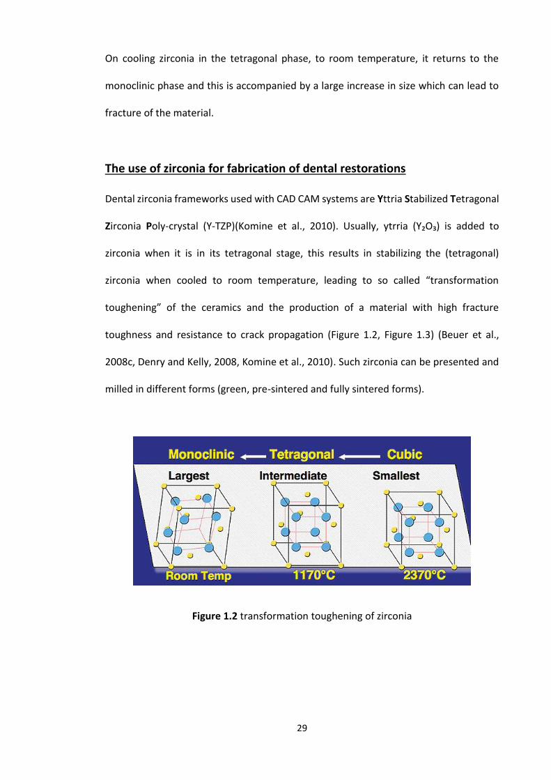
29
On cooling zirconia in the tetragonal phase, to room temperature, it returns to the
monoclinic phase and this is accompanied by a large increase in size which can lead to
fracture of the material.
The use of zirconia for fabrication of dental restorations
Dental zirconia frameworks used with CAD CAM systems are Yttria Stabilized Tetragonal
Zirconia Poly-crystal (Y-TZP)(Komine et al., 2010). Usually, ytrria (Y₂O₃) is added to
zirconia when it is in its tetragonal stage, this results in stabilizing the (tetragonal)
zirconia when cooled to room temperature, leading to so called “transformation
toughening” of the ceramics and the production of a material with high fracture
toughness and resistance to crack propagation (Figure 1.2, Figure 1.3) (Beuer et al.,
2008c, Denry and Kelly, 2008, Komine et al., 2010). Such zirconia can be presented and
milled in different forms (green, pre-sintered and fully sintered forms).
Figure 1.2 transformation toughening of zirconia
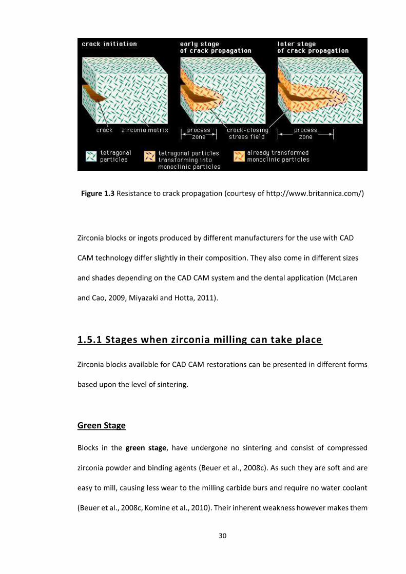
30
Figure 1.3 Resistance to crack propagation (courtesy of http://www.britannica.com/)
Zirconia blocks or ingots produced by different manufacturers for the use with CAD
CAM technology differ slightly in their composition. They also come in different sizes
and shades depending on the CAD CAM system and the dental application (McLaren
and Cao, 2009, Miyazaki and Hotta, 2011).
1.5.1 Stages when zirconia milling can take place
Zirconia blocks available for CAD CAM restorations can be presented in different forms
based upon the level of sintering.
Green Stage
Blocks in the green stage, have undergone no sintering and consist of compressed
zirconia powder and binding agents (Beuer et al., 2008c). As such they are soft and are
easy to mill, causing less wear to the milling carbide burs and require no water coolant
(Beuer et al., 2008c, Komine et al., 2010). Their inherent weakness however makes them

31
susceptible to breakage in the manufacturing process. Copings and frameworks are then
fired and undergo approximately 25.0 % shrinkage which has to be accounted for in the
CAD process (Beuer et al., 2008c).
Pre-sintered (white stage)
Pre-sintered blocks have undergone a partial sintering heat process leading to
approximately 5.0 % shrinkage of the material. The blocks at this stage have no binder
and are rather porous still (Beuer et al., 2008c). Milling of zirconia blocks in the pre-
sintered form is carried out either dry with carbide burs or wet (coolant) with diamond
burs (Reich et al., 2005a). Again softness of the material means that milling leads to little
wear of the milling burs, but the pre-sintering process ensures that the milled
restorations are more robust. The milled restoration is then further sintered undergoing
an approximate 20.0 % shrinkage, again accounted for in the CAD software.
Fully sintered
Blocks of fully sintered zirconia can also be milled and have the advantage that no
sintering and hence shrinkage has to be accounted for. Milling fully sintered zirconia
blocks requires water coolant and diamond burs. Although their use has the advantages
mentioned they have some disadvantages namely a more robust milling machine is
required (high rigidity and stability), a longer milling time is needed, there is high wear
of burs and milling fully sintered zirconia can lead to stresses formation within the
material which leads to cracks formation and fracture of the restoration (Tinschert et
al., 2001a, Tinschert et al., 2001b).
32
1.5.2 Survival of zirconia
The goal of prosthodontic treatment is to restore aesthetics, speech and function. Metal
ceramic indirect dental restorations have been used for over 50 years (Sundh et al.,
2005), which makes them, to date, the preferred dental restoration, due to their proven
track record. Despite this, failure can occur due to clinical problems such as caries or due
to technical problems such as fracture, aesthetics, or ceramic chipping (Tartaglia et al.,
2011).
In recent years aesthetic restorations (all ceramic) have become more popular,
therefore researchers have started focusing on and comparing the new all ceramic
material to the metal ceramics, mainly regarding fit, survival and success rates (Sailer et
al., 2007b, Gonzalo et al., 2009).
Both metal ceramic and zirconia restorations should be durable. That is they should
demonstrate survival and success. The survival of a restoration means, that it continues
to function in the mouth even if it suffers some minor problems. Success is when the
restoration survives in an intact anatomical shape, function and aesthetics (Potiket et
al., 2004, Agustín-Panadero et al., 2014).
Studies on the survival rate of dental zirconia restorations are summarised in Table 1.4,
most of them being on bridges. It is clear that observation periods range from 1 to 13
years, zirconia bridges have greater complications compared to zirconia single crowns
(Agustín-Panadero et al., 2014), as there is less studies on zirconia single crowns.
As zirconia oxide is opaque, a crown core constructed of this is made aesthetic by
applying a translucent feldspathic ceramic veneer on the top of the zirconia core.
33
Although, the ceramic veneer improves the appearance of the zirconia restoration, the
studies in Table 1.4 show a high rate of veneer fracture (chipping). The amount of
veneer fracture ranges from 6.0 % to 15.0 % in the period of between 3 to 5 years
(Agustín-Panadero et al., 2014). This is higher than the values of veneer fracture in metal
ceramic restorations which is said to be around 4.0 % (Tan et al., 2004). Veneer fracture
can be as a result of a weak bond between the zirconia and the feldspathic veneering
ceramics.
In contrast, a 10 years prospective study of metal ceramic dental restorations, followed
a total 466 restorations. It concluded that metal ceramic restorations have good
longevity, but just like veneered zirconia restorations, the main problem was with
fracture (cracking or chipping) of the veneering porcelain overlying the metallic core
(Reitemeier et al., 2013).
Chipping of veneering ceramic is more common that delamination from zirconia based
restorations, and to minimize this risk full contour zirconia restorations can be
constructed (Burke et al., 2013), this is mainly because aesthetic, all-zirconia
restorations can now be produced.
Comparing the zirconia based restoration outcomes and survival rates with metal
ceramic dental restorations, as mentioned earlier, it can be seen that the same factors
affect both types of restoration. However, even with fracture of the veneering porcelain
zirconia restorations will continue to appear more aesthetic, compared to metal
ceramics as the latter are more likely to exhibit shine through of the metal core (Magne
et al., 1999).
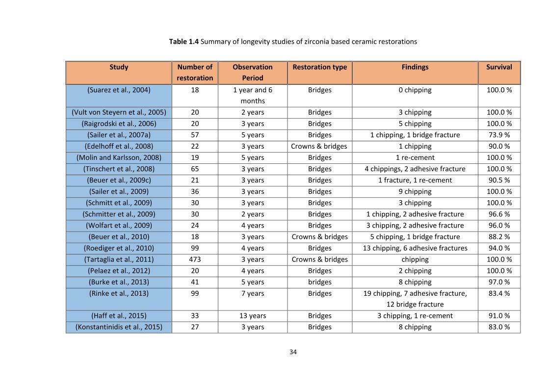
34
Table 1.4 Summary of longevity studies of zirconia based ceramic restorations
Study Number of
restoration
Observation
Period
Restoration type Findings Survival
(Suarez et al., 2004) 18 1 year and 6
months
Bridges 0 chipping 100.0 %
(Vult von Steyern et al., 2005) 20 2 years Bridges 3 chipping 100.0 %
(Raigrodski et al., 2006) 20 3 years Bridges 5 chipping 100.0 %
(Sailer et al., 2007a) 57 5 years Bridges 1 chipping, 1 bridge fracture 73.9 %
(Edelhoff et al., 2008) 22 3 years Crowns & bridges 1 chipping 90.0 %
(Molin and Karlsson, 2008) 19 5 years Bridges 1 re-cement 100.0 %
(Tinschert et al., 2008) 65 3 years Bridges 4 chippings, 2 adhesive fracture 100.0 %
(Beuer et al., 2009c) 21 3 years Bridges 1 fracture, 1 re-cement 90.5 %
(Sailer et al., 2009) 36 3 years Bridges 9 chipping 100.0 %
(Schmitt et al., 2009) 30 3 years Bridges 3 chipping 100.0 %
(Schmitter et al., 2009) 30 2 years Bridges 1 chipping, 2 adhesive fracture 96.6 %
(Wolfart et al., 2009) 24 4 years Bridges 3 chipping, 2 adhesive fracture 96.0 %
(Beuer et al., 2010) 18 3 years Crowns & bridges 5 chipping, 1 bridge fracture 88.2 %
(Roediger et al., 2010) 99 4 years Bridges 13 chipping, 6 adhesive fractures 94.0 %
(Tartaglia et al., 2011) 473 3 years Crowns & bridges chipping 100.0 %
(Pelaez et al., 2012) 20 4 years Bridges 2 chipping 100.0 %
(Burke et al., 2013) 41 5 years bridges 8 chipping 97.0 %
(Rinke et al., 2013) 99 7 years Bridges 19 chipping, 7 adhesive fracture,
12 bridge fracture
83.4 %
(Haff et al., 2015) 33 13 years Bridges 3 chipping, 1 re-cement 91.0 %
(Konstantinidis et al., 2015) 27 3 years Bridges 8 chipping 83.0 %
35
1.6 CAD CAM
Dentists have for many years been technology focused. As regards the fabrication of
indirect restorations in the 1980s Computer Aided Design Computer Aided
Manufacturing (CAD CAM) (Beuer et al., 2008c) was introduced to the profession which
potentially permits such restorations to be fabricated at the chairside. With advances in
computing such technology has since become popular and is considered to be one of
the most practical and convenient methods for fabricating dental restorations.
CAD CAM technology is likely to take over from conventional chairside and laboratory
techniques in the future, for it offers high precision restoration production at a lower
unit cost facilitated by a new generation of computer literate, digitally and
technologically minded dentists and technicians. Such advances have already been seen
with a big leap in dental radiography, towards digital imaging (Wenzel and Gröndahl,
1995) and cone beam CT technology (Brullmann and Schulze, 2015), as well as changes
in computerized medical records and digital dental photography (Desai and Bumb,
2013).
1.6.1 History of dental CAD CAM
The first application of CAD CAM technology was initiated and described by Duret and
Preston, the pioneers of dental CAD CAM technology, in the early 1970s (Duret and
Preston, 1991). In this early system, the tooth preparation was scanned using an
intraoral digitizer (optical impression) allowing a 3-D graphic to be reconstructed on a
computer monitor. This in turn allowed virtual design (CAD) of the morphology of the
indirect dental restoration (crown) by application of editable software and the
36
construction from a ceramic block of the restoration with the aid of a numerically
controlled milling machine (CAM).
A dental CAD CAM system was first produced commercially for the first time by Duret
and co-workers called Sopha® (Sopha, bioconcept, France) (Duret and Preston, 1991,
Miyazaki et al., 2009). However, it was not widely available, because of its complexity
and cost (Mantri and Bhasin, 2010). Despite this lack of commercial uptake research in
the 1970s and 80s to develop a new dental CAD CAM system based on Duret’s system
continued (Rekow, 2006).
It was however not until Mörmann, together with the help and knowledge from his
friend Dr. Brandestini (an electrical engineer), worked to develop the CAD CAM
technology further, that a system could manufacture a tooth-colored posterior indirect
dental restoration (inlay) (Mörmann et al., 1989, Miyazaki and Hotta, 2011). The system
was called computer-assisted CERamic REConstruction, and was known widely as
CEREC.
The development of dental CAD CAM systems is still continuing with an aim of improving
the technology. Although, today there are more systems available in the market (Table
1.5) it is interesting to note that there is as yet no internationally agreed standard for
the many CAD CAM systems and interoperability of this technology (R.G Chadwick-
Personal communication). The only published ISO standard to date relates to laboratory
based CAD CAM scanners (ISO 12836: 2015 Dentistry- Digitizing devices for CAD CAM
systems for indirect dental restorations – test methods for assessing accuracy).

37
Table 1.5 Development timeline of CAD CAM dental systems
Year Scientist /Systems Place/company
1970s Duret and Preston University of Southern California, USA
1984 Sopha system Sopha bioconcept.
1980s Mörmann and Brandestini University of Zurich, Switzerland
1987 Cerec® 1 Sirona Dental Systems
1989 Precident DCS Dental, Allschwil, Germany
1993 Procera® Nobel BioCare, Yorba Linda, CA
1994 Cerec® 2 Sirona Dental Systems
2000 Cerec® 3 Sirona Dental Systems
2001 Cerec® InLab Sirona Dental Systems
2001 Cercon® DeguDent, Dent
2002 Everest® Kavo Dental, Lake Zurich, IL
2002 Lava™ 3M ESPE, St. Paul, MN
2008 E4D PLANMECA, E4D
CEREC dental CAD CAM system
The CEREC system was the first commercially available CAD CAM system. It was able to
scan the cavity directly in the patient mouth using a compact intra-oral camera. As a
result of the data collected, the design and fabrication of the indirect dental restoration
(ceramic inlay) is all made at chairside. Although it was an evolution in constructing
indirect dental restorations, it had two limitations. At that time, the system was limited
to inlay restorations and secondly the constructed indirect dental restoration had no
occlusal morphology (Mörmann et al., 1989). More information about the development
of the CEREC system will be introduced in the “CAD CAM systems available” section.
38
As a result of further research and development, CEREC 2 was produced and introduced
in 1994; the system gave the user (dentist or technician) more options of dental
restorations when compared with CEREC 1. The CEREC 2 system was the same as CEREC
1, displaying the captured data in 2-D. In the new millennium, with all of the upgrades
in technology and 3-D systems in dentistry, CEREC saw the need and necessity to
upgrade their system. This was when CEREC 3 was introduced to the market.
As regards the milling component, CEREC 1 and 2 were only one-bur-systems, whereas
CEREC 3 is a two-bur-system; however, it was not until 2003 when the three dimensional
(3-D) virtual editing display was available with CEREC 3 system. As a result of the
introduction of the 3-D display to the CEREC 3 system, the design and production of
indirect dental restorations became easier, both for the dental office and the laboratory
technician (Mörmann, 2006).
1.6.2 CAD CAM components
Whilst there are a number of different dental CAD CAM systems available on the market,
in general, they all consist of four components: a scanner (laboratory or intra oral
scanner), CAD (3D designing software), CAM (Milling device) and finally a furnace used
for semi-sintered zirconia (Miyazaki et al., 2009, Ting-Shu and Jian, 2015) to bring about
structured rearrangements and enhance the porcelain physical properties.
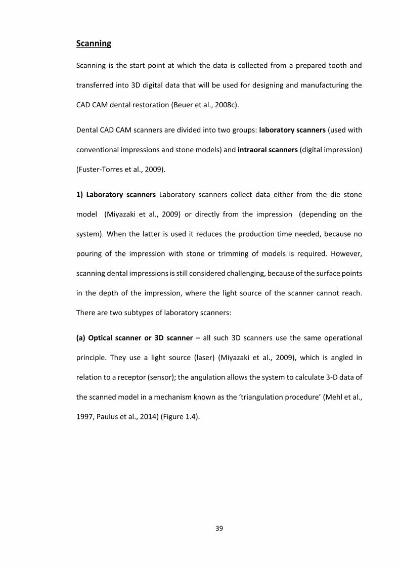
39
Scanning
Scanning is the start point at which the data is collected from a prepared tooth and
transferred into 3D digital data that will be used for designing and manufacturing the
CAD CAM dental restoration (Beuer et al., 2008c).
Dental CAD CAM scanners are divided into two groups: laboratory scanners (used with
conventional impressions and stone models) and intraoral scanners (digital impression)
(Fuster-Torres et al., 2009).
1) Laboratory scanners Laboratory scanners collect data either from the die stone
model (Miyazaki et al., 2009) or directly from the impression (depending on the
system). When the latter is used it reduces the production time needed, because no
pouring of the impression with stone or trimming of models is required. However,
scanning dental impressions is still considered challenging, because of the surface points
in the depth of the impression, where the light source of the scanner cannot reach.
There are two subtypes of laboratory scanners:
(a) Optical scanner or 3D scanner – all such 3D scanners use the same operational
principle. They use a light source (laser) (Miyazaki et al., 2009), which is angled in
relation to a receptor (sensor); the angulation allows the system to calculate 3-D data of
the scanned model in a mechanism known as the ‘triangulation procedure’ (Mehl et al.,
1997, Paulus et al., 2014) (Figure 1.4).

40
Figure 1.4 The triangulation procedure in optical scanners between the laser source
and the receptor sensor (courtesy of Stefan Paulus)
The scanning process is a result of well-defined light lines which are projected by the
light source (laser) on the scanned object, the line angulation is based on the distance
between the camera and the light source (laser), to allow the camera to capture all
details from the scanned model of the prepared tooth. Having more than one camera
improves the accuracy by covering more areas and angulations. A motion system
supporting several axes holding and positioning the scanned model (teeth) towards the
light source is necessary. Each light line resembles a 3D contour line, hence the multiple
3D contours. The scanning head moves in a precise linear axis when the light source is a
laser (multiple lines), whereas the scanning head is fixed with a white light scanner
(several shifted line patterns from a central position). As mentioned previously, multiple
cameras and a multi-axis stage can increase the scanning accuracy, by allowing to scan
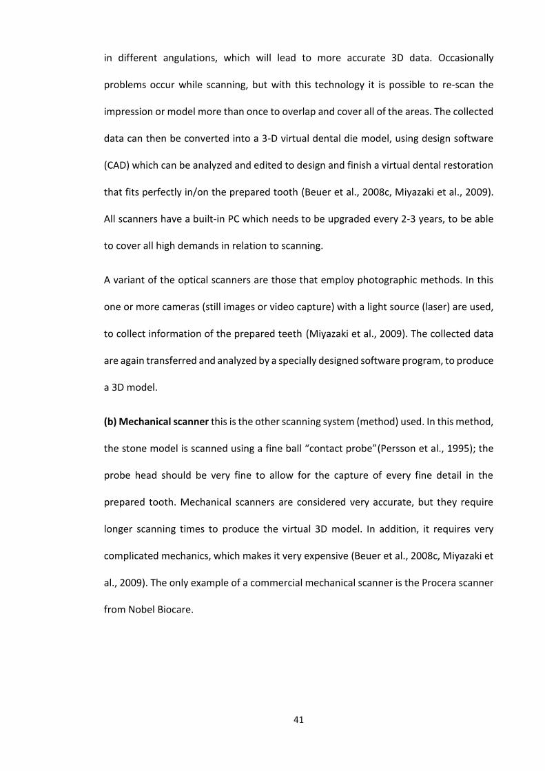
41
in different angulations, which will lead to more accurate 3D data. Occasionally
problems occur while scanning, but with this technology it is possible to re-scan the
impression or model more than once to overlap and cover all of the areas. The collected
data can then be converted into a 3-D virtual dental die model, using design software
(CAD) which can be analyzed and edited to design and finish a virtual dental restoration
that fits perfectly in/on the prepared tooth (Beuer et al., 2008c, Miyazaki et al., 2009).
All scanners have a built-in PC which needs to be upgraded every 2-3 years, to be able
to cover all high demands in relation to scanning.
A variant of the optical scanners are those that employ photographic methods. In this
one or more cameras (still images or video capture) with a light source (laser) are used,
to collect information of the prepared teeth (Miyazaki et al., 2009). The collected data
are again transferred and analyzed by a specially designed software program, to produce
a 3D model.
(b) Mechanical scanner this is the other scanning system (method) used. In this method,
the stone model is scanned using a fine ball “contact probe”(Persson et al., 1995); the
probe head should be very fine to allow for the capture of every fine detail in the
prepared tooth. Mechanical scanners are considered very accurate, but they require
longer scanning times to produce the virtual 3D model. In addition, it requires very
complicated mechanics, which makes it very expensive (Beuer et al., 2008c, Miyazaki et
al., 2009). The only example of a commercial mechanical scanner is the Procera scanner
from Nobel Biocare.
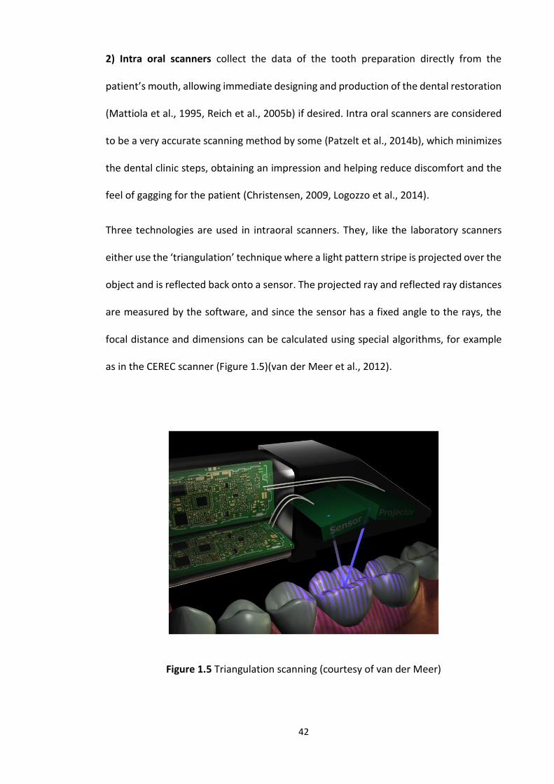
42
2) Intra oral scanners collect the data of the tooth preparation directly from the
patient’s mouth, allowing immediate designing and production of the dental restoration
(Mattiola et al., 1995, Reich et al., 2005b) if desired. Intra oral scanners are considered
to be a very accurate scanning method by some (Patzelt et al., 2014b), which minimizes
the dental clinic steps, obtaining an impression and helping reduce discomfort and the
feel of gagging for the patient (Christensen, 2009, Logozzo et al., 2014).
Three technologies are used in intraoral scanners. They, like the laboratory scanners
either use the ‘triangulation’ technique where a light pattern stripe is projected over the
object and is reflected back onto a sensor. The projected ray and reflected ray distances
are measured by the software, and since the sensor has a fixed angle to the rays, the
focal distance and dimensions can be calculated using special algorithms, for example
as in the CEREC scanner (Figure 1.5)(van der Meer et al., 2012).
Figure 1.5 Triangulation scanning (courtesy of van der Meer)
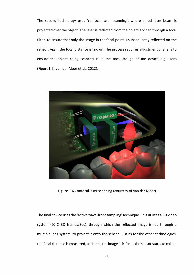
43
The second technology uses ‘confocal laser scanning’, where a red laser beam is
projected over the object. The laser is reflected from the object and fed through a focal
filter, to ensure that only the image in the focal point is subsequently reflected on the
sensor. Again the focal distance is known. The process requires adjustment of a lens to
ensure the object being scanned is in the focal trough of the device e.g. iTero
(Figure1.6)(van der Meer et al., 2012).
Figure 1.6 Confocal laser scanning (courtesy of van der Meer)
The final device uses the ‘active wave-front sampling’ technique. This utilizes a 3D video
system (20 X 3D frames/Sec), through which the reflected image is fed through a
multiple lens system, to project it onto the sensor. Just as for the other technologies,
the focal distance is measured, and once the image is in focus the sensor starts to collect
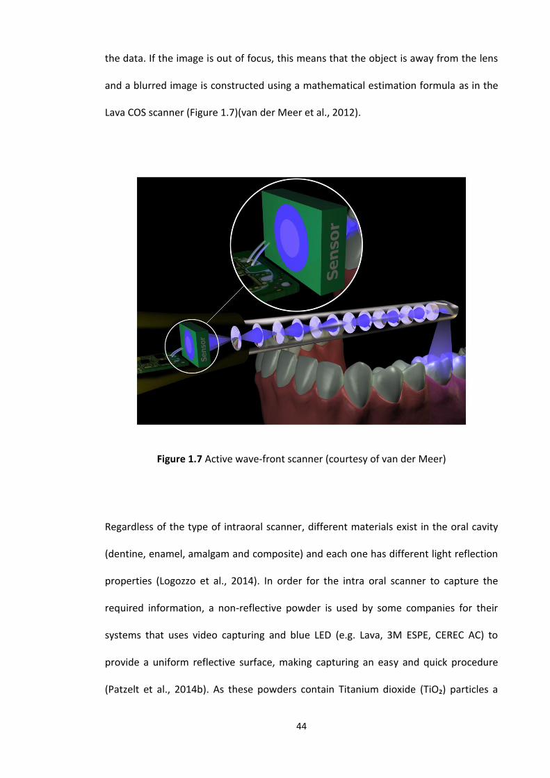
44
the data. If the image is out of focus, this means that the object is away from the lens
and a blurred image is constructed using a mathematical estimation formula as in the
Lava COS scanner (Figure 1.7)(van der Meer et al., 2012).
Figure 1.7 Active wave-front scanner (courtesy of van der Meer)
Regardless of the type of intraoral scanner, different materials exist in the oral cavity
(dentine, enamel, amalgam and composite) and each one has different light reflection
properties (Logozzo et al., 2014). In order for the intra oral scanner to capture the
required information, a non-reflective powder is used by some companies for their
systems that uses video capturing and blue LED (e.g. Lava, 3M ESPE, CEREC AC) to
provide a uniform reflective surface, making capturing an easy and quick procedure
(Patzelt et al., 2014b). As these powders contain Titanium dioxide (TiO₂) particles a

45
secondary function, useful when stitching together multiple scans into one image, is that
they provide reference points to permit the assembly of such data into one image(R.G
Chadwick- personal communication). Not all systems however require the use of non-
reflective powder, such as the systems that use laser technology in scanning and
measuring the distances (E4D, iTero).
During scanning, the practitioner should ensure that the finish line and margins of the
prepared tooth are clear and easily captured by the scanner; a retraction cord or paste
can be used to make the margins clearer, but it should be removed or washed away
before the scanning process. A large number of intra oral scanners are available from
different companies as summarized in Table 1.6.
The quality of the final CAD CAM restoration depends greatly on the accuracy of the
scanner, so the scanning procedure should be very precise in recording, the margins,
undercuts, contact points, adjacent teeth, gingiva, and opposing dentition (Kohorst et
al., 2011).
Table 1.6 Shows different intra oral scanner available in the market
Intra oral scanner Manufacturer Image type Light source
CEREC® Sirona Dental System GMBH Multiple images Blue light
iTero CADENT LTD Multiple images Red laser
E4D D4D TECHNOLOGIES, LLC Multiple images Laser
Lava™ C.O.S 3M ESPE Video Pulsating blue
light
IOS FastScan IOS TECHNOLOGIES, INC. 3 images Laser
DENSYS 3D DENSYS LTD. 2 images Light
DPI-3D DIMENSIONALPHOTONICS
INTERNATIONAL, INC.
Multiple images Light
3D Progress MHT S.p.A. (IT) and MHT Optic
Research AG
3 images ----------------
directScan HINT - ELS GMBH Multiple images ---------------
Trios 3SHAPE A/S Multiple images ---------------
46
Accuracy
Most companies do not disclose how accurate their machines are and do not mention
how they measured the accuracy (Vlaar and van der Zel, 2006); it is mainly determined
in studies and research carried out after the machine is released for commercial use.
However recently a new ISO standard was published to assess the accuracy of laboratory
scanners (ISO 12836: 2015 Dentistry- Digitizing devices for CAD CAM systems for indirect
dental restorations – test methods for assessing accuracy) and a standard is being
drafted for intraoral scanners assessments of accuracy (R.G Chadwick – Personal
communication).
The accuracy of the dental scanners depends highly on their manufacturing quality.
Leading manufacturer’s scanners usually have and use better production tools and
materials. Another factor that can affect the scanner hardware which will affect the
scanning accuracy is rough handling, in transporting the machine from one place to
another. The scanners should therefore be re-calibrated when they are moved to a new
place or even when the temperature is changed, which should be scheduled work, as
part of maintaining the scanner. Some companies provide scanners with a calibration
block/object, with a known accuracy factor that is higher than the scanner accuracy
capability. It is very important to know that the software algorithm cannot calculate and
compensate for any temperature effect on the scanner hardware (complex expansion
and contraction). Since the scanner contains welding, fasteners and glued sections, and
can be used under varying workloads, this explains how important calibration is to
maintain accurate scanning results (Hollenbeck et al., 2012).
Another factor that can have an effect on accuracy is the size of the scanner. Larger
scanners achieve better results because of their stability and the fact that most of the
47
parts are automated, which will reduce any possible movement and subjective error
during the scanning process (Hollenbeck et al., 2012).
Scan Speed and productivity
Scan speed is a very important feature when choosing a scanner, because it will have an
effect on the productivity of the dental laboratory, and finishing the case. As with
accuracy, there are no standards to compare the scanners and there is no information
released from the companies to compare it with any marketing claims. It is claimed that
scanning varies from 30 seconds to several minutes (Hollenbeck et al., 2012).
The scan speed alone will not reveal the capabilities of the scanner in terms of
productivity. A whole workflow should be considered, starting from creation of the
order, scanning, designing and ending with milling the dental restoration. Even if
different systems are compared from this point of view, this will result in large
performance variation. Usually, fully automated systems allow the user to spend less
time on the machine, and on the overall scan process. As mentioned earlier, this reduces
human error. Manually processed and controlled systems require more time, because
many things need to be adjusted (camera brightness, die position, etc.). Some systems
provide a multi-die plate, which reduces the time required to change the dies to
compare a single die scanner. This feature allows the operator to use spare time (while
the scanner is finishing the scanning process) to design a restoration in the CAD software
(Hollenbeck et al., 2012).
48
The indications for each type of dental scanner are an important factor that needs to be
considered along with the speed and accuracy. The indications include long span
bridges, dentures and implant abutments, etc. Since there are some cheap low quality
scanners which are non-upgradable and support only basic indications which will limit
the work that can be produced.
The CAD software will also limit the type of restoration that can be produced. Therefore,
this makes it more convenient to have the scanner and the CAD software from the same
system, because the developer will integrate more options which will offer a better and
more optimized workflow (Hollenbeck et al., 2012).
CAD
Each Company provides its own and unique software that can be used to design
different dental restorations using 3D technology (Beuer et al., 2008c). The CAD
software has a pre-loaded library including different designs of crowns and bridge
frameworks, full anatomical crowns and bridges, inlays and onlays. Newer software can
produce even more types of dental restorations, for example implant abutments,
removable partial denture frameworks, and orthodontic appliances. Once the data are
uploaded to the CAD software, the laboratory steps will be performed virtually after
filling the job order (digital laboratory request). First a virtual die will be generated,
followed by die sectioning, then the finish-line will need to be marked and finally
designing of the required dental restoration, a step by step detailed information is
described in laboratory study 1. The CAD software starts by providing a proposal of the
ideal restoration that fits the prepared tooth, in relation to the finish-line, contact point

49
and opposing dentition. Then, the dentist can adjust the restoration (fissures, cusps,
etc.).
Previously the companies produced closed software, which is compatible with their
system only and cannot be used with any other system. Recently, the manufacturers
started to produce an open source program (software) which allowed the use of
different scanners with different CAD systems (Miyazaki et al., 2009). Unfortunately,
there has not been much published about the CAD software, and each company
considers this to be its own secret to protect future development and updates to its
software.
File format
The file format produced by CAD software is either STereo-Lithography files or Standard
Triangle Language (STL). The STL file are considered to be open files. This type of file
format is native to the CAD software, which makes it easy for all of the companies to
produce a CAM machine which is compatible with most of the available CAD software.
However, some companies have their own file format (proprietary), which makes it only
compatible with their milling device (Mehl et al., 1997); but, they are all moving towards
the open access format, which can be used with a wider variety of companies and
materials (van Noort, 2012). Finally the 3-D virtually designed dental restoration is sent
to the milling device as digital data (STL file), where it will be milled to the final dental
restoration.
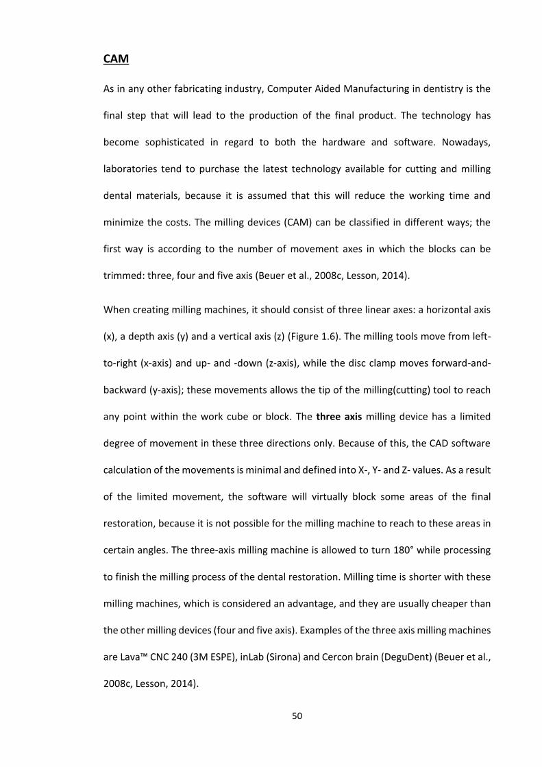
50
CAM
As in any other fabricating industry, Computer Aided Manufacturing in dentistry is the
final step that will lead to the production of the final product. The technology has
become sophisticated in regard to both the hardware and software. Nowadays,
laboratories tend to purchase the latest technology available for cutting and milling
dental materials, because it is assumed that this will reduce the working time and
minimize the costs. The milling devices (CAM) can be classified in different ways; the
first way is according to the number of movement axes in which the blocks can be
trimmed: three, four and five axis (Beuer et al., 2008c, Lesson, 2014).
When creating milling machines, it should consist of three linear axes: a horizontal axis
(x), a depth axis (y) and a vertical axis (z) (Figure 1.6). The milling tools move from left-
to-right (x-axis) and up- and -down (z-axis), while the disc clamp moves forward-and-
backward (y-axis); these movements allows the tip of the milling(cutting) tool to reach
any point within the work cube or block. The three axis milling device has a limited
degree of movement in these three directions only. Because of this, the CAD software
calculation of the movements is minimal and defined into X-, Y- and Z- values. As a result
of the limited movement, the software will virtually block some areas of the final
restoration, because it is not possible for the milling machine to reach to these areas in
certain angles. The three-axis milling machine is allowed to turn 180° while processing
to finish the milling process of the dental restoration. Milling time is shorter with these
milling machines, which is considered an advantage, and they are usually cheaper than
the other milling devices (four and five axis). Examples of the three axis milling machines
are Lava™ CNC 240 (3M ESPE), inLab (Sirona) and Cercon brain (DeguDent) (Beuer et al.,
2008c, Lesson, 2014).
51
Due to the need for milling both sides of the working blocks, to allow for the creation of
a better detailed occlusal and fitting surface of the restoration, a new axis has been
incorporated into some milling machines, the fourth axis (a) (Figure 1.6). With the fourth
axis in the milling machines, most shapes in restorative dentistry can be created,
because the machine is able to cut above the mid-line (occlusal surface) which is also
known in the milling industry as the ‘parting line’, and then the block will be flipped
around the “a” axis and milling below the same line (fitting surface). As a conclusion, the
extra turn allows for greater adjustment of the dental restorations with high vertical
dimension such as bridge abutments, long clinical crowns and in implant cases, and a
result materials and milling time will be saved. An example of a four axis milling machine
is Zeno (Wieland-Imes, Ivoclar Vivadent) (Beuer et al., 2008c, Lesson, 2014).
A fifth axis has been added by some manufacturers the (b) axis; five axis devices are just
like the three and four axis devices in regard to the primary movements (x, y, z and a),
in addition to the possibility of a perpendicular movement to the fourth axis (a) (Figure
1.8). The extra movement allows the milling of extra complicated geometry
substructures or full dental restorations and an example of a five axis milling machine is
Lava™ CNC 500 (3M ESPE) (Beuer et al., 2008c). Although 4 and 5 axis milling machines
can produce more complex dental restorations the quality of the final restoration
depends highly on the scanning process.
Usually, the four axis milling machine performs ‘indexed milling’, which includes
incremental tilts and pauses along the a-axis, while the tool changes its place of milling.
On the other hand, the 5 axis milling machines provides a ‘continuous milling’, as a result
of the b axis rotation, which allows the continuous contact of the milling tools with the

52
working block, reducing the working time. However, the bigger milling machines are
better than the small ones (Beuer et al., 2008c, Lesson, 2014).
Figure 1.8 The axes of a three (X, Y & Z), four (X, Y, Z & A) and five (X, Y, Z, A & B) axis
CAM milling machines
1.6.3 CAD CAM classification
There are different ways to classify the CAD CAM systems, either according to the
scanning and production method or according to the milling process.
The CAD CAM systems can be classified into two types depending on their scanning and
production device (Mantri and Bhasin, 2010):
1. In-office (chairside): A variety of system permutations come under this heading: only
the scanner (intra-oral, e.g. Lava C.O.S), scanner and designing software (e.g. E4D) or
having all the components of the CAD CAM system in the clinic (scanner, designing
software and milling device, e.g. CEREC system).
53
2. Dental laboratory: After making the impression (digital or conventional) in the clinic,
the remaining production steps (designing and milling) are made in the laboratory. In
the laboratory either the laboratory scanner, designing software or the milling device
are available in the laboratory, or the scanner and the designing software alone.
The other classification is according to the milling process, either dry or wet. The milling
process (dry or wet) depends mainly on the type of materials being milled (Beuer et al.,
2008c). Semi-sintered zirconia oxide are mainly used with dry processing milling devices,
which have several benefits such as: there is no absorption of moisture by the dry
zirconia oxide so it can be sintered immediately, and cost effective when it comes to the
tools, because less tool wear will occur during the milling process, which makes the
milling device cheaper, in addition newer materials which have been introduced can also
be dry milled such as resin. An example of dry milling devices are Zeno 4030 (Wieland-
Imes, Ivoclar Vivadent), Lava™ CNC 500 (3M ESPE) and Cercon® brain.
The wet processing milling machines are used with fully sintered glass ceramics and
metals, where the coolant liquid is used to protect the diamond or carbide cutting burs
against overheating while processing the restoration. Usually, fully sintered ceramics are
used with wet processing devices, as such the material is milled to the precise size and
shape as no subsequent shrinkage in a sintering process takes place. Examples of wet
process milling machines include Everest (KaVo), Zeno 8060 (Wieland-Imes), inLab
(Sirona).
54
There are two techniques for producing the final restoration, either subtractive, which
is the dominant technology, or the additive technique.
The Subtractive processing technique depends mainly on cutting the material away
mechanically (milling) to achieve the desired object. Using this technique allows for the
fabrication of sophisticated shapes with a reduced fabrication time (van Noort, 2012). It
is however considered to be wasteful as the material removed during the fabrication
process cannot be reused. An example of the subtractive processing technique is the
Lava (3M, ESPS) milling machine and zirconia blocks(Giordano and McLaren, 2010). In
an attempt to save money and reduce the fabrication cost mainly in mass production
manufacturer, some companies have moved to the additive manufacturing techniques.
The Additive manufacturing technique is described by the American Society for Testing
and Materials (ASTM) as: “the process of joining materials to make objects from 3D
model data, usually layer upon layer”. In this process the works is created from a series
of cross sectional layers, which are printed one on top of the other; to produce a 3D
model (object). Using this technique insures that there is no waste of materials.
Originally it was called Rapid Prototyping which was introduced in the 1980s to
manufacture prototypes and models of objects. Today the additive manufacturing
technique allows the production of full scale models, which helps in customizing and
modifying the object before producing the final product (Stoker et al., 1992, Kernan and
Wimsatt Iii, 2000, Cohen et al., 2009, van Noort, 2012). An example of the additive
technique is the production of resin Stereolithographic (SLA) models from computer
aided design via 3D printer.
55
1.6.4 Advantages of using CAD CAM
Dental CAD CAM systems offer advantages when fabricating dental restorations namely
(Miyazaki et al., 2009, Beuer et al., 2008c):
1) Improved quality of the final dental restorations (internal and marginal fit).
2) Cost effectiveness (fixed price compared with metals, e.g. gold).
3) Reduced labour and working time.
4) Introduction of new modified dental materials (stronger, dense, and with a superior
aesthetics).
1.6.5 Materials available for the use with CAD CAM
Almost all types of fixed (crowns, bridges, implant abutments, inlays and onlays) and
removable (removable partial dentures) dental restorations in addition to orthodontic
appliances can be constructed using CAD CAM technology.
Different CAD CAM systems are compatible with different types of materials (Table 1.7).
Silica-based ceramics, infiltrated ceramics and oxide high performance ceramics
(Aluminum Oxide and Yttrium stabilized Zirconium Oxide) are the most widely used
materials with CAD CAM technology (Beuer et al., 2008c). The materials are available in
blocks and are either mono-chromatic or poly chromatic (Baroudi and Ibraheem, 2015).
In addition to ceramics (Table 1.8), metals (titanium, titanium alloys and chrome cobalt
alloys), waxes and resin materials may be used with dental CAD CAM systems (Beuer et
al., 2008c).
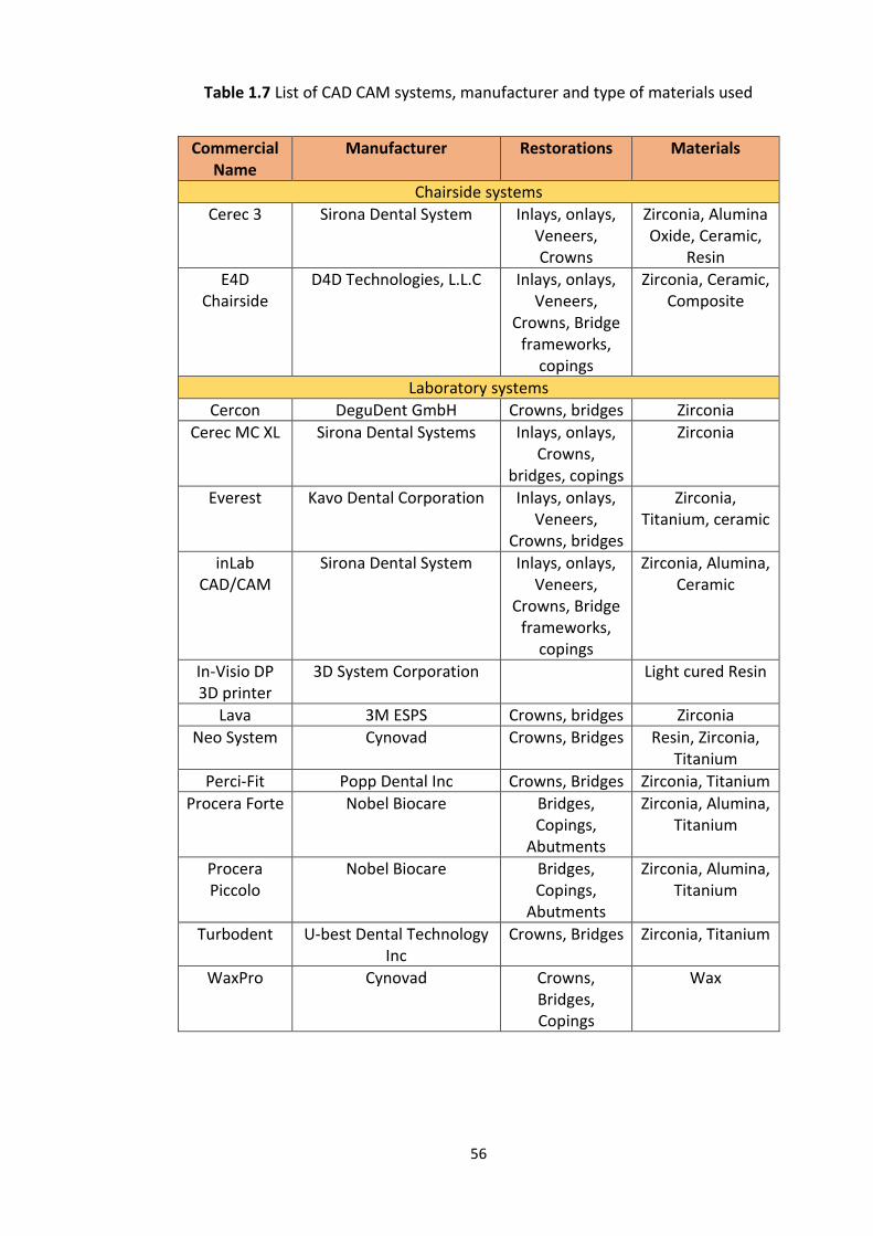
56
Table 1.7 List of CAD CAM systems, manufacturer and type of materials used
Commercial Name
Manufacturer Restorations Materials
Chairside systems
Cerec 3 Sirona Dental System Inlays, onlays, Veneers, Crowns
Zirconia, Alumina Oxide, Ceramic,
Resin
E4D Chairside
D4D Technologies, L.L.C Inlays, onlays, Veneers,
Crowns, Bridge frameworks,
copings
Zirconia, Ceramic, Composite
Laboratory systems
Cercon DeguDent GmbH Crowns, bridges Zirconia
Cerec MC XL Sirona Dental Systems Inlays, onlays, Crowns,
bridges, copings
Zirconia
Everest Kavo Dental Corporation Inlays, onlays, Veneers,
Crowns, bridges
Zirconia, Titanium, ceramic
inLab CAD/CAM
Sirona Dental System Inlays, onlays, Veneers,
Crowns, Bridge frameworks,
copings
Zirconia, Alumina, Ceramic
In-Visio DP 3D printer
3D System Corporation Light cured Resin
Lava 3M ESPS Crowns, bridges Zirconia
Neo System Cynovad Crowns, Bridges Resin, Zirconia, Titanium
Perci-Fit Popp Dental Inc Crowns, Bridges Zirconia, Titanium
Procera Forte Nobel Biocare Bridges, Copings,
Abutments
Zirconia, Alumina, Titanium
Procera Piccolo
Nobel Biocare Bridges, Copings,
Abutments
Zirconia, Alumina, Titanium
Turbodent U-best Dental Technology Inc
Crowns, Bridges Zirconia, Titanium
WaxPro Cynovad Crowns, Bridges, Copings
Wax
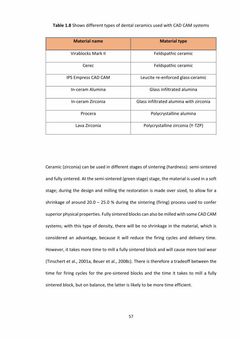
57
Table 1.8 Shows different types of dental ceramics used with CAD CAM systems
Material name Material type
Virablocks Mark II Feldspathic ceramic
Cerec Feldspathic ceramic
IPS Empress CAD CAM Leucite re-enforced glass-ceramic
In-ceram Alumina Glass infiltrated alumina
In-ceram Zirconia Glass infiltrated alumina with zirconia
Procera Polycrystalline alumina
Lava Zirconia Polycrystalline zirconia (Y-TZP)
Ceramic (zirconia) can be used in different stages of sintering (hardness): semi-sintered
and fully sintered. At the semi-sintered (green stage) stage, the material is used in a soft
stage; during the design and milling the restoration is made over sized, to allow for a
shrinkage of around 20.0 – 25.0 % during the sintering (firing) process used to confer
superior physical properties. Fully sintered blocks can also be milled with some CAD CAM
systems; with this type of density, there will be no shrinkage in the material, which is
considered an advantage, because it will reduce the firing cycles and delivery time.
However, it takes more time to mill a fully sintered block and will cause more tool wear
(Tinschert et al., 2001a, Beuer et al., 2008c). There is therefore a tradeoff between the
time for firing cycles for the pre-sintered blocks and the time it takes to mill a fully
sintered block, but on balance, the latter is likely to be more time efficient.
58
1.6.6 Work Flow to construct dental restorations
When a tooth is prepared for an indirect restoration which is to be made using CAD CAM
technology, there are two different techniques possible to obtain an impression of the
prepared tooth, namely a conventional impression or a digital impression (Miyazaki et
al., 2009).
The conventional technique usually involves taking an elastomeric silicone impression
to produce a working model. Depending on the type of laboratory scanner available,
either the elastomeric silicone impression itself or the stone model created from the
impression is scanned (Beuer et al., 2008c). This is to collect all of the data needed to
design and fabricate the dental restoration.
Alternative, a digital impression can be made using an intra-oral scanner. The scan of
the prepared teeth together with a scan of the opposing arch can then be mounted on
a virtual articulator, using a digital occlusal record. The digital model can then be
sectioned virtually to produce the working die. This data can be sent to a production
center to order an articulated SLA working model. The models are used during the
veneering process of the ceramic framework in order to obtain correct contacts points
and occlusion (Beuer et al., 2008c).
After scanning the impression, stone model or using the intra oral scanner, designing
the dental restoration using the CAD software and fabricating the final restoration
follow the same steps for both techniques. The final dental restoration may either be
constructed in the same clinic/dental lab if the milling machine is available or the design
can be sent to a production center for fabrication (Figure 1.9).
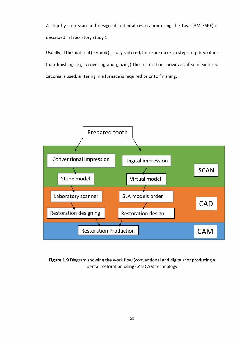
59
A step by step scan and design of a dental restoration using the Lava (3M ESPE) is
described in laboratory study 1.
Usually, if the material (ceramic) is fully sintered, there are no extra steps required other
than finishing (e.g. veneering and glazing) the restoration; however, if semi-sintered
zirconia is used, sintering in a furnace is required prior to finishing.
Figure 1.9 Diagram showing the work flow (conventional and digital) for producing a
dental restoration using CAD CAM technology
Prepared tooth
Conventional impression
SLA models order
Digital impression
Stone model Virtual model
Laboratory scanner
Restoration designing Restoration design
Restoration Production
CAD
CAM
SCAN
60
1.6.7 CAD-on veneering technique
Recently a new veneering technique called CAD-on has been introduced to fabricate the
veneering layer using Lithium-disilicate (Aboushelib et al., 2008, Beuer et al., 2009f,
Kanat et al., 2014a, Kanat et al., 2014b, Torabi et al., 2015b). Some CAD CAM software
will allow the fabrication of a two part restoration, a coping and veneering cover. The
benefit of this step is that if the ceramic is semi-sintered, both parts are sintered at once,
followed by a fusion firing cycle where a connector layer (fusion glass-ceramic) is applied
to the inner surface of the veneering ceramic and to the outer surface of the coping. The
veneering part is then seated under pressure over the coping, the excess connecting
layer removed with a small brush and the two layers fired together to complete the
fusion process (Beuer et al., 2009f, Torabi et al., 2015b). When the CAD-on veneering
technique was compared with the layering and press-on veneering technique, the
results showed that all three veneering techniques led to an increase in the marginal
gap of the zirconia based restoration compared with the coping alone; the zirconia
coping mean gap was 35.0 µm, which increased to 63.1 µm with the layering veneer
technique, 50.6 µm using the pressing technique and finally 51.5 µm with the CAD-on
veneering technique (Torabi et al., 2015b). Although all veneering techniques led to an
increase in marginal gap all of them produced small marginal gaps and clinically
acceptable results.
61
1.7 Tooth preparation design
The tooth preparation for crowns and conventional bridge retainers involves removing
tooth structure to create space for a new restoration and, as such, it is not a conservative
procedure. One of the most common complications when preparing teeth is loss of pulp
vitality (Saunders and Saunders, 1998, Cheung et al., 2005). Losing pulp vitality can be
due to many factors such as the resin-based materials used when restoring teeth for
indirect dental restorations, excessive tooth preparation, high exothermic activity of
provisional restorative materials and traumatic occlusion due to incorrect restoration
occlusal contour (Christensen, 2005). This section discusses tooth preparation,
therefore, losing pulp vitality can be reduced or avoided by intermittent cutting and
using a high speed hand-piece with plenty of water to reduce the heat and vibration and
ensuring definitive restorations are correctly contoured (Ricketts and Bartlett, 2011).
Tooth preparation for indirect full coverage dental restorations is therefore a fine
balance of creating sufficient space for the restoration but preserving as much tooth
tissue as possible in addition to protecting the pulp and adjacent tooth(Christensen,
2005).
Since tooth preparation for crowns and bridge abutments is an important step to ensure
perfect mechanical, biological and aesthetic outcomes of the final restoration, six
principles should be considered (Goodacre et al., 2001, Blair et al., 2002):
1. Amount of tooth reduction
2. Finish-line
3. Preparation taper
4. Line angle form
62
5. Surface texture
6. Retention and Resistance
1.7.1 Amount of tooth reduction
To be able to construct an indirect dental restoration a considerable amount of tooth
structure should be reduced during tooth preparation. The type of indirect dental
restoration that will be used, will indicate the amount of tooth reduction required which
is usually between 0.5 to 2 mm for fully coverage restorations (Ricketts and Bartlett,
2011). There are factors that can affect the amount of reduction for example the
position and alignment of the tooth, occlusal relationships, aesthetics, position of the
gingival margin, smile line and the tooth morphology (Goodacre et al., 2001).
Metal dental castings are very strong in thin sections, which makes a 0.5 mm finish-line
depth adequate to construct an all metal dental restoration; this is considered to be the
most conservative indirect full coverage dental restoration (Shillingburg, 1997). But
because of its color, it is only used for posterior teeth. Porcelain fused to metal crowns
used in the aesthetic zone require tooth reduction of between 1.5 to 2 mm; the depth
is needed because the metal framework should be covered by an opaque layer of
porcelain followed by layering of aesthetic ceramics which helps to achieve a better
appearance. Traditional all ceramic (PJC type) crowns, on the other hand, need extensive
tooth preparation of around 2 mm all around to provide space for a which is bulk enough
restoration to withstand occlusal forces. However, with all of the improvements made
to the ceramic materials and bonding to tooth tissue to enhance ceramic strength, 1.5
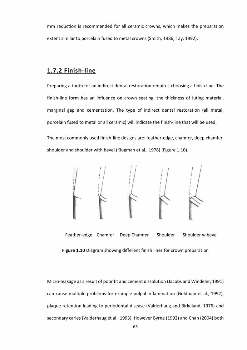
63
mm reduction is recommended for all ceramic crowns, which makes the preparation
extent similar to porcelain fused to metal crowns (Smith, 1986, Tay, 1992).
1.7.2 Finish-line
Preparing a tooth for an indirect dental restoration requires choosing a finish line. The
finish-line form has an influence on crown seating, the thickness of luting material,
marginal gap and cementation. The type of indirect dental restoration (all metal,
porcelain fused to metal or all ceramic) will indicate the finish-line that will be used.
The most commonly used finish-line designs are: feather-edge, chamfer, deep chamfer,
shoulder and shoulder with bevel (Klugman et al., 1978) (Figure 1.10).
Feather-edge Chamfer Deep Chamfer Shoulder Shoulder w bevel
Figure 1.10 Diagram showing different finish lines for crown preparation
Micro-leakage as a result of poor fit and cement dissolution (Jacobs and Windeler, 1991)
can cause multiple problems for example pulpal inflammation (Goldman et al., 1992),
plaque retention leading to periodontal disease (Valderhaug and Birkeland, 1976) and
secondary caries (Valderhaug et al., 1993). However Byrne (1992) and Chan (2004) both

64
stated that the finish-line had no effect on the fitting of a cemented crown (Byrne, 1992,
Chan et al., 2004b).
A number of studies have examined the effect of the finish line on the fit of indirect
dental restorations (Table 1.9). Different preparation designs of marginal finish-line
(feather edge, slight chamfer, deep chamfer, beveled shoulder, and non-beveled
shoulder) have been used to study their effect on fracture resistance and their influence
on the marginal adaptation of the CAD/CAM zirconia framework. As a consequence of
the information gained from these studies, shoulder and chamfer preparation finish-
lines are recommended for all ceramic full coverage retainers. In root canal treated
teeth that are compromised coronally, a slight chamfer has been recommended (Beuer
et al., 2009b, Comlekoglu et al., 2009); this study however, contradicts the findings of
another laboratory study which recommended that a shoulder, shoulder with a bevel
or heavy chamfer finish-lines can lead to the best marginal fit (Byrne, 1992).
By examining different studies related to the fit of full ceramic crowns or bridges, the
most common finish-lines used are shoulder and chamfer (Table 1.9).
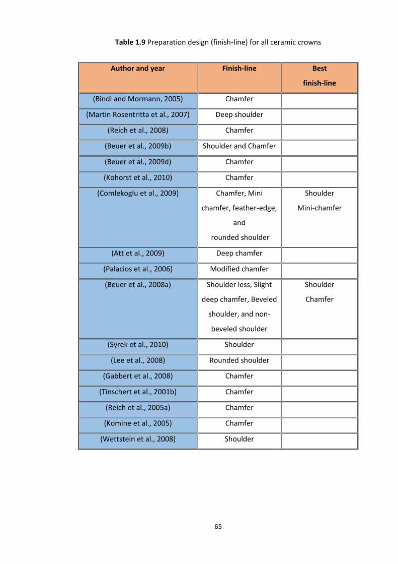
65
Table 1.9 Preparation design (finish-line) for all ceramic crowns
Author and year Finish-line Best
finish-line
(Bindl and Mormann, 2005) Chamfer
(Martin Rosentritta et al., 2007) Deep shoulder
(Reich et al., 2008) Chamfer
(Beuer et al., 2009b) Shoulder and Chamfer
(Beuer et al., 2009d) Chamfer
(Kohorst et al., 2010) Chamfer
(Comlekoglu et al., 2009) Chamfer, Mini
chamfer, feather-edge,
and
rounded shoulder
Shoulder
Mini-chamfer
(Att et al., 2009) Deep chamfer
(Palacios et al., 2006) Modified chamfer
(Beuer et al., 2008a) Shoulder less, Slight
deep chamfer, Beveled
shoulder, and non-
beveled shoulder
Shoulder
Chamfer
(Syrek et al., 2010) Shoulder
(Lee et al., 2008) Rounded shoulder
(Gabbert et al., 2008) Chamfer
(Tinschert et al., 2001b) Chamfer
(Reich et al., 2005a) Chamfer
(Komine et al., 2005) Chamfer
(Wettstein et al., 2008) Shoulder

66
The finish line can be located in one of three locations, either supra-gingival, equi-
gingival or sub-gingival. The supra-gingival finish-lines are usually recommended,
because they have the lowest impact on the periodontium (Silness, 1970). Supra-gingival
margins are mainly considered in areas where aesthetics are not of paramount
importance and the core is also supra-gingival. Preparing a tooth with a supra-gingival
finish-line has additional advantages other than protecting the periodontium, it is easier
to prepare, easy to duplicate using impression material (no need for gingival retraction),
easy to remove any extra luting cement, easy to clean for the patient and finally, easy
to check the integrity of the dental restoration at follow up (Nugala et al., 2012).
It was believed that the equi-gingival finish-line can accumulate plaque which can lead
to gingival inflammation and might lead to gingival recession creating a potentially
unsightly margin. However, today, this is not thought to be the case, as restorations can
be provided with smooth margins and highly polished materials, so the equi-gingival
margin is now considered by some to be just as acceptable as the supra-gingival finish-
line (Khuller and Sharma, 2009, Nugala et al., 2012).
There are however certain situations when a sub-gingival finish-line is required due to
aesthetics and/or restorative considerations (Nugala et al., 2012). With the new
developments in dental materials, adhesive dentistry and resin cements, the sub-
gingival finish-line can be used where aesthetic demands are high and in the case of
discolored teeth; however, this requires perfect tooth preparation and impression, and
a well-fitting and contoured restoration to ensure the health of the periodontal
structures (Brandau et al., 1988). In cases of short clinical crowns, a subgingival margin
can provide greater length of the prepared tooth to increase retention and resistance
form (Sharma et al., 2012). It may also be necessary to prepare beyond a subgingival
67
restoration due to an extensive carious lesion or subgingival tooth fracture, or to provide
a ferrule for endodontically treated teeth (Sreedevi et al., 2015). When considering the
sub-gingival finish-line, the biological width should be respected and the sub-gingival
preparation shouldn’t exceed half the gingival pocket (0.5 - 1 mm) so as not to disturb
the long junctional epithelium or connective tissues, because this is a very important
factor for tooth and dental restoration longevity (Nugala et al., 2012).
1.7.3 Retention and Resistance
Retention is defined as that which prevents the dislodgment of a restoration along the
path of insertion or long axis of the tooth preparation, whereas Resistance is the
prevention of dislodgment of the restoration by oblique or horizontal forces.
For a crown to resist dislodgment, it is important to have an adequate occlusal-cervical
dimension in relation to the preparation taper (Blair et al., 2002). There is a linear
relationship between the preparation taper and the resistance to dislodgment and this
is considered as providing the primary retention or resistance form to a crown
preparation.
In a study which tested dies with 5, 10 and 15° taper and 3, 4, 6, 8 and 10 mm occlusal
preparation height; they found that 3 mm occlusal-cervical height was adequate to
provide resistance to dislodgment when the taper was 10° (Woolsey and Matich, 1978).
In another study by Maxwell et al. (1990), crown preparations with an occlusal-cervical
preparation height of 1, 2, 3, 4 and 5 mm and all with a 6° occlusal convergence angle
were compared and again 3 mm height was found to be the minimal occlusal-cervical
68
dimension required to provide adequate resistance to dislodgment (Maxwell et al.,
1990).
Secondary retention and resistance forms can be provided if the primary retention is
poor, for example in short clinical crowns, by adding boxes, pins and grooves to the
preparation. The retention and resistance of a dental restoration are related to the
longevity of the restoration (Sharma et al., 2012).
1.7.4 Preparation taper
The preparation taper (convergence angle) refers to the angle between two opposing
prepared axial surfaces and is an important feature which gives the prepared tooth its
retention and resistance form (see section below on retention and resistance form).
As far back as 1923, Prothero recommended that a taper of 2 - 5° was the optimum
when preparing a tooth for a crown (Prothero, 1923, Goodacre et al., 2001). However,
this was not subjected to scientific studies until the 1950s when Jorgenson used
different taper angles and tested the retention of crowns when tensile forces were
applied (Jorgensen, 1955); the results supported the earlier 2 - 5° recommendation by
Prothero. Although this was recommended, clinically it is very difficult to achieve and
the reported mean convergence angle produced by dentists ranges between 12° and
27° (Noonan and Goldfogel, 1991, Smith et al., 1999). It has also been found that when
molar teeth are prepared they have greater preparation taper compared with the
anterior and premolar teeth (Annerstedt et al., 1996), which is probably due to the
greater difficulty with access and trying to avoid damaging the adjacent teeth.
69
In 2004, convergence angles ranging from 0° to 70° were studied in different
experiments; the optimum retention being obtained was between 2° and 20° with peak
retention at 10° (Chan et al., 2004b). Beuer et al. also studied the effect of different
preparation angles (4°, 8°, and 12°) on zirconia crowns in relation to marginal and
internal fit; here, 12° was recommended as the best angle for full ceramic crowns (Beuer
et al., 2008b, Beuer et al., 2009b). On balance 12 degrees would appear to be the most
appropriate and realistic minimum preparation taper achieved.
1.7.5 Line angle form
The internal line angles are the junctions or meeting lines between prepared tooth
surfaces. Usually the line angles produced during the preparation process are sharp,
which will lead to stress concentration (Nicholls, 1974). It is recommended that the line
angles should be rounded during the tooth preparation to reduce areas of stress
concentration especially in relation to all ceramic crowns (Mizrahi, 2008, Ricketts and
Bartlett, 2011). A round angle facilitates the laboratory procedure by not trapping air
bubbles during fabrication of both the gypsum model and wax pattern, as poor
reproduction can adversely affect the fit and seating of the restoration.
1.7.6 Surface texture
After completing the preparation, the surface texture of the prepared tooth should be
smooth as this can improve marginal fit (Tjan and Sarkissian, 1986). This having been
said some studies have shown that surface roughness can increase the retention of the
restoration with certain types of cements (Juntavee and Millstein, 1992). A pragmatic
approach may be to use a fine grit diamond bur to at least finish off the finish line to
70
improve fit and leave the rest of the axial walls slightly rougher to maximize retention
(Ricketts and Bartlett, 2011).
1.8 Impressions
A summary of the ideal properties of dental impression materials include:
1. Biocompatible, and have a pleasant taste and odour.
2. Fluid enough to flow between the teeth and surrounding tissues.
3. Good working time and long shelf life.
4. Dimensionally stable, and can be disinfected.
5. Compatible with die and cast materials. (Bonsor and Pearson, 2013).
Many materials are available for recording dental impressions and based upon the
consensus of opinion from many material text books (Anusavice et al., 2012, Bonsor and
Pearson, 2013, Van Noort, 2013) these materials together with their advantages and
disadvantages are summarized in Table 1.10.
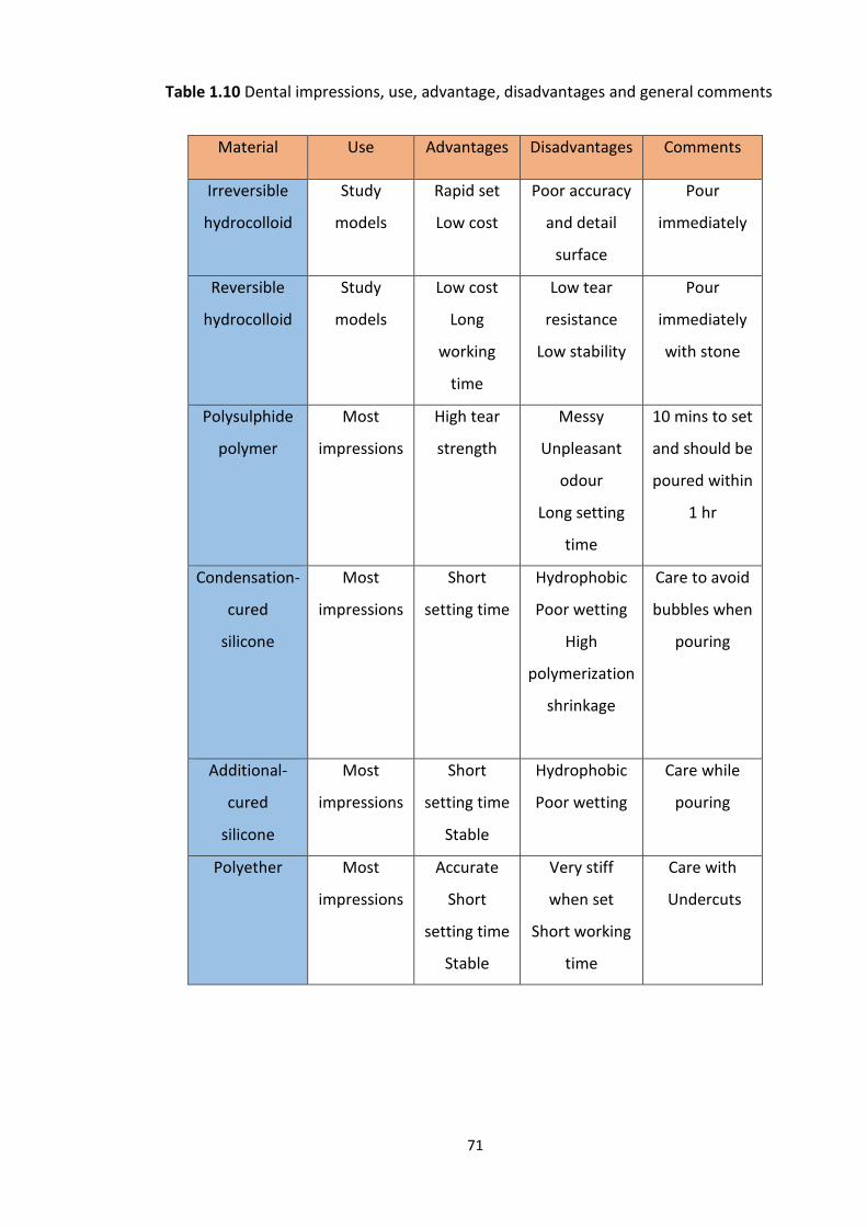
71
Table 1.10 Dental impressions, use, advantage, disadvantages and general comments
Material Use Advantages Disadvantages Comments
Irreversible
hydrocolloid
Study
models
Rapid set
Low cost
Poor accuracy
and detail
surface
Pour
immediately
Reversible
hydrocolloid
Study
models
Low cost
Long
working
time
Low tear
resistance
Low stability
Pour
immediately
with stone
Polysulphide
polymer
Most
impressions
High tear
strength
Messy
Unpleasant
odour
Long setting
time
10 mins to set
and should be
poured within
1 hr
Condensation-
cured
silicone
Most
impressions
Short
setting time
Hydrophobic
Poor wetting
High
polymerization
shrinkage
Care to avoid
bubbles when
pouring
Additional-
cured
silicone
Most
impressions
Short
setting time
Stable
Hydrophobic
Poor wetting
Care while
pouring
Polyether Most
impressions
Accurate
Short
setting time
Stable
Very stiff
when set
Short working
time
Care with
Undercuts
72
1.8.1 Conventional and Digital Impression/Digital
scanning
Conventional impressions taken in metallic or plastic stock trays are daily procedures
carried out in dental practices and it was the only available technique for transferring
the details of prepared teeth from the patient’s oral cavity to the laboratory
(Hamalian et al., 2011, Gjelvold et al., 2015). Although, conventional impressions are
widely used, and are the preferred technique for the majority of practitioners
(Henkel, 2007), complications are commonly observed and reported such as
improper impression tray selection, improper soft tissue management, distortion of
the impression material during dis-infection and/or pouring of the impression
(Christensen, 2008, Beuer et al., 2008c, Touchstone et al., 2010).
Previously, metallic trays were commonly used for impressions of tooth preparations
of one or more units, as they benefited from being rigid, thus providing the stability
required for the impression material. However, difficulty was experienced in removal
of the tray adhesive and this posed a problem in relation to cross infection control.
As such plastic trays are now more commonly used as they are disposable and
eliminates potential cross infection issues. Plastic trays do ,however, suffer from
being flexible (lack rigidity), which makes it mandatory to use rigid impression
materials to ensure the stability needed (Ceyhan et al., 2003, Christensen, 2008,
Bensel et al., 2013).
A digital impression technique using intra oral scanners was introduced for
transferring the information from the patient’s oral cavity to the laboratory using the
digital technology, and is described in detail in section 1.6.2.
73
1.8.2 Cross infection control in relation to impressions
Disinfecting dental impressions is an important procedure to carry out prior to
sending them to the laboratory to eliminate cross infection (Wassell et al., 2002b).
As dental impressions can be a source of bacterial contamination, education
regarding impression disinfection is important to the dentist, dental nurse and dental
technician (Almortadi and Chadwick, 2010).
Disinfecting conventional impressions is achieved using liquid solutions which can
lead to an irreversible distortion of the impression, especially if immersed for a long
time. This will affect the final restoration fit (Adabo et al., 1999, Taylor et al., 2002,
Hiraguchi et al., 2012). To prevent or minimise any distortion of the impression
material, the manufacturer’s recommendations regarding the concentration of the
disinfecting solution and immersion time should be followed. Spray disinfectants can
be used as these have less effect on the dimensional stability of the impression
material (Suprono et al., 2012).
Whilst there is no risk in transferring contaminated material to the laboratory when
using a digital impression, there is a risk of cross infection between patients and
dentist when using the intra-oral scanner. To address this some companies
recommend that the camera head is either covered by a disposable sleeve or
removable sterilisable plastic sleeve and the head of the camera then wiped with
commercially available disinfectant or immersed in a disinfectant chemical. Digital
impressions also eliminate the distortions that can happen to conventional
impressions as a result of the disinfection procedure (Glassman, 2009).
74
1.8.3 Models
The dental models not only aid the dentist and laboratory technician in studying the
dental case carefully and in detail, so helping in treatment planning, but they are also
essential in the production of the indirect restoration. Most dental models are
produced using gypsum products, for example type IV gypsum (Kim et al., 2015).
Dental models can therefore be divided into three types, depending on the usage:
1. Study model (cast), used for treatment planning purposes.
2. Working cast, used for construction of dental restorations.
3. Refractory model, used with metal framework wax-up and for certain all ceramic
restorations (Bonsor and Pearson, 2013).
It has been recommended that the dental technician waits between 24 to 48 hours
before the stone model is handled for prosthetic work, this is because the dental
stone is considered unstable during the setting period (Silva et al., 2012). In addition
to being unstable, high rates of delayed setting expansion have been reported with
dental stone (Heshmati et al., 2002).
To achieve a successful restoration it requires optimal internal and marginal cement
gaps (Soriani et al., 2007). The cement gap (internal and marginal) on conventional
stone models is created by using die spacer paint (Lee and Ibbetson, 2000); the
number of die spacer coats applied on the stone die will determine the cement gap
size. Although it can be argued that increasing the cement thickness might lead to a
weak bond between the restoration and abutment tooth, it has been shown that up
75
to 16 coats of die relief does not affect the retention of the cemented restoration
(Passon et al., 1992).
To compensate for the problems associated with conventional stone models, a new
technology has been used to produce stereolithographic models (SLA or SL; also
known as optical fabrication, photo-solidification, solid free-form fabrication, solid
imaging and resin printing) using a process known as rapid prototyping which is
described in detail in the next section.
1.8.4 Rapid prototyping
Rapid prototyping is the process by which software and hardware work together to
produce a customized 3D model from 3D digital data (Beguma and Chhedat, 2014).
The 3D digital data is collected using 3D scanners or 3D radiographs such as
computerized tomography (Zein et al., 2002).
Rapid prototyping is widely used in many industries such as transportation, energy,
consumer goods, education and in the healthcare sector for medical models, surgical
guides, hearing aids, implantable devices and highly complicated models in dentistry
and medicine (Nayar et al., 2015). A 3D model will help the medical and dental
practitioners during the treatment planning by reproducing the problem as a model
in a natural fashion.
76
Two techniques are available to produce the 3D models, namely subtractive or
additive techniques (Nayar et al., 2015).
The subtractive technique uses a full block of the required material and cutting tools
to shape the block into the desired model shape in true CAD CAM fashion (Torabi et
al., 2015a). This technique has some limitations, for example, the materials used
should be strong, hard and sterilisable, but with the available materials, it is difficult
to obtain high quality models. A second limitation lies with the milling machines
which have limited and restricted motion, and as such some complex shapes or
difficult angles cannot be milled, limiting their use for replicating more basic shapes.
As with all new technology advancement (electrical discharge machining,
electromechanical machining, electron beam machining, photochemical machining
and ultrasonic machining), this technique has become faster and is able to achieve
higher degrees of sophistication, but not to the degree that the additive technique
can achieve (van Noort, 2012).
The additive technique, is defined by the American society for testing and materials
as ‘The process of joining materials to make objects from 3D model data, usually layer
upon layer, as opposed to subtractive manufacturing methodologies’. Additive
techniques have an advantage over subtractive techniques because they can
fabricate models with much more complex and difficult details (undercuts, voids, and
complex geometries) such as sinuses and canals (blood and nerves) (Liu et al., 2006).
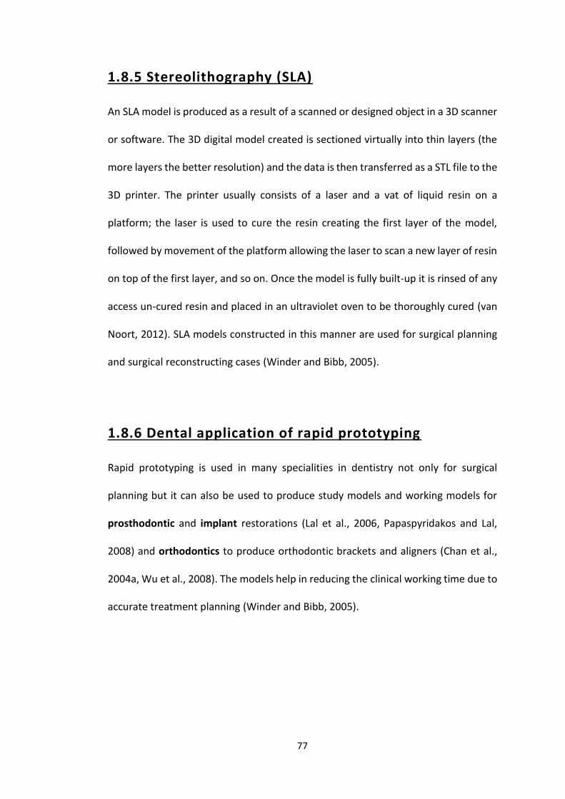
77
1.8.5 Stereolithography (SLA)
An SLA model is produced as a result of a scanned or designed object in a 3D scanner
or software. The 3D digital model created is sectioned virtually into thin layers (the
more layers the better resolution) and the data is then transferred as a STL file to the
3D printer. The printer usually consists of a laser and a vat of liquid resin on a
platform; the laser is used to cure the resin creating the first layer of the model,
followed by movement of the platform allowing the laser to scan a new layer of resin
on top of the first layer, and so on. Once the model is fully built-up it is rinsed of any
access un-cured resin and placed in an ultraviolet oven to be thoroughly cured (van
Noort, 2012). SLA models constructed in this manner are used for surgical planning
and surgical reconstructing cases (Winder and Bibb, 2005).
1.8.6 Dental application of rapid prototyping
Rapid prototyping is used in many specialities in dentistry not only for surgical
planning but it can also be used to produce study models and working models for
prosthodontic and implant restorations (Lal et al., 2006, Papaspyridakos and Lal,
2008) and orthodontics to produce orthodontic brackets and aligners (Chan et al.,
2004a, Wu et al., 2008). The models help in reducing the clinical working time due to
accurate treatment planning (Winder and Bibb, 2005).

78
1.9 Cements
All indirect restorations are fixed to the teeth using dental luting cements. Choosing
the correct cement is as important as all the other stages in the provision of indirect
restorations, because this will determine the long-term success of the restoration
(Pameijer, 2012). Over the last century and a half a large number of luting cements
have been used and some are listed in Table 1.11.
Table 1.11 A timeline of the development of dental luting cements
Cement Year
Zinc phosphate 1870s
Silicate cement 1940s
Polycarboxylate 1972
Composite resin cement 1975
Glass ionomer cement 1976
Resin-cement 1986
Resin-modified glass ionomer cement 1995
Self-etching and adhesive resin cements 2000s
79
1.9.1 Ideal properties of a luting cement
The ideal dental luting cements should meet clinical and physical properties both
during mixing and cementation (Rosenstiel et al., 1998, Rickman and Satterthwaite,
2010, Pameijer, 2012). The properties include:
1. Biocompatibility with the teeth and surrounding oral tissue.
2. Adhesion and bonding to both the restoration and the tooth structure.
3. It should have sufficient resistance and retention strength against all forces.
4. Low viscosity to ensure flow of the cement into all fine details and to allow full
seating of the restoration.
5. Have perfect marginal adaptation to prevent leakage.
6. The material should be available in different shades (when used to cement ceramic
or composite indirect restorations).
7. Easy to handle, sufficient working time and easy to clean.
8. Not soluble.
9. Not imbibe to water.
1.9.2 Classification of dental cements
There are different types of luting cements available on the market (Table 1.12)
which can be classified into either conventional or contemporary cements with each
type having its usage and recommendations (Rickman and Satterthwaite, 2010,
Sümer and Değer, 2011, Pameijer, 2012, Mante et al., 2013).

80
Table 1.12 Cement classification, commercial names, use and their recommendation
A study in 2003, showed that using resin cements led to higher (double) retention on
the indirect dental restoration when compared with zinc phosphate and
conventional glass ionomer cement using different tooth preparation taper(Figure
1.11) (Zidan and Ferguson, 2003).
Material Classification Use Recommendation
DeTrey Zinc
Phosphate
Zinc Phosphate Metal based
restorations
Mechanical
retention
Co
nve
nti
on
al
Poly-F Plus Zinc
Polycarboxylate
Polycarboxylate Metal based
restorations
Mechanical
retention
Ketac Cem,
Fuji cements
Conventional GIC Metal based
restorations
Moisture control
Rely X Luting,
Fuji PLUS,
Fuji CEM
Resin Modified
GIC
Metal based
restorations and
Ceramic based
restorations
Mechanical
retention
Co
nte
mp
ora
ry Variolink,
Calibra, Metabond
RelyX Arc
Composite Resins Dentine bonded crowns
and
conventional
restorations
Mechanical
and chemical
retention
RelyX Unicem Self-adhesive
resin cement
All types of restoration
except veneers
Mechanical
and chemical
retention

81
Figure 1.11 Comparisons between mean retentive strength of different degree of
taper within each luting agent tested (Zidan and Ferguson, 2003)
0
1
2
3
4
5
6
7
8
Zinc phosphate Glass ionomer Resin Resin (Metabond)
6° 12° 24°
82
1.10 Literature review conclusion and overall aim
The foregoing has reviewed the literature, in relation to different dental materials
(metal and ceramics) and their use for fabricating indirect dental restorations with a
particular emphasis on dental CAD CAM and digital work flow for the production of
zirconia based restorations. There is clearly a rapid increase in interest, research and
clinical usage of CAD CAM and digital technology in dentistry and is therefore likely
to dominate restorative dentistry in the future. As such, this provided the inspiration
for this thesis.
As the survival and longevity of any indirect dental restoration depends on its fit,
strength and its appearance, the overall aims of the subsequent studies in this thesis
were to investigate the accuracy of fit of indirect zirconia based dental restorations
produced using dental CAD CAM with differing variables including cementation
seating force, differing thicknesses of zirconia and span length, effect of veneering
ceramic placement and whether made from a digital or conventional impression. In
addition the strength (the ability to resist fracture by a force) of bridges made with
different thicknesses of zirconia and whether veneered with ceramic or not were
investigated. In relation to the appearance and fit of zirconia based restorations an
audit was also carried out which aimed to measure the dental team and patients’
satisfaction with all ceramic zirconia based dental restorations provided for patients
at Dundee Dental Hospital and School in addition to an economic evaluation. Each
individual aspect is the subject of the subsequent six chapters, each containing the
specific aims of the study and discussion of the outcomes.
83
1.11 Sample size calculation
The sample size for each of the subsequent five laboratory studies was calculated
using the on-line calculator: http://www.surveysystem.com/sscalc.htm
The population size was set to 2000 as this could represent the number of people
that might require indirect dental restorations within a year within an average dental
hospital. With a confidence level of 95 % and a marginal error of 25 %, the results
showed that 15 bridges could represent the population. This number is also
consistent with previously published work in this field (Khng, 2013). As such in all the
laboratory studies in this thesis 15 bridges were produced for each type of zirconia
based indirect dental restorations investigated.
84
Chapter 2
Laboratory study 1
Force applied by dentists during
cementation of all zirconia three
unit bridges and the impact on
seating
85
Laboratory study 1
Force applied by dentists during cementation of all
zirconia three unit bridges and the impact on seating
2.1 Introduction
Cementing an indirect dental restoration is the final step after finishing all the clinical
and laboratory stages, and it is considered to be an equally important stage that can
affect the longevity of the restoration (Behr et al., 2008). For patients a successful
cemented restoration is one that fits perfectly, never de-cements, and does not
cause any pain or discomfort. In addition to this the dentist is also concerned with a
perfect marginal fit so that no micro-leakage and/or secondary caries occurs
(Mustafa et al., 2010). To achieve these goals, after fabricating the indirect dental
restoration, the choice of an appropriate luting cement and cementation technique
are very important (Wassell et al., 2002a).
The luting cement chosen fills the interface between the fit surface of the restoration
and the prepared tooth surface and, in some instances, additionally provides a bond
between the two (Rosenstiel et al., 1998). Apart from the luting cement type selected
and cementation technique used the force applied by the practitioner might also
have an effect on the accurate seating of the indirect dental restoration to achieve
the fit ideals described above. In the literature there is no clear recommendation as
to the force required to achieve the best seat and hence fit of a restoration. Only two
studies have measured the force applied by dentists, both of which were carried out

86
on single unit crowns, and did not study the impact that the applied force had on the
fit of the restoration (Black and Amoore, 1993, Mustafa et al., 2010).
2.2 Aims and objectives
The aims of this study were to compare the force applied by ten different dentists
and by the same dentists at different time intervals during the cementation of all
zirconia bridges manufactured by Computer Aided Design Computer Aided
Manufacturing (CAD CAM) and to investigate the impact that this has on the seating
and fit of the cemented bridges.
2.3 Material and Methods
Tooth preparation
Two plastic teeth (Frasaco GmbH, Germany) were mounted in Frasaco jaws (standard
working model A-3), one first pre-molar (tooth 24) and one first molar (tooth 26),
were prepared for a three unit fixed-fixed all zirconia bridge to replace the second
pre-molar tooth (tooth 25) (Figure 2.1 A). Each tooth was prepared in the laboratory
with a high speed hand piece and new chamfer crown preparation tapered diamond
bur (Komet dental, Code number 856-314-016) with water coolant to a
predetermined standard: deep chamfer finish-line 1.0 - 1.5 mm around the entire
circumference of the tooth preparation, 10° - 12° total occlusal convergence angle
(taper) and 1.5 - 2.0 mm occlusal reduction (Byrne, 1992, Chan et al., 2004b, Beuer
et al., 2008a, Beuer et al., 2008b, Beuer et al., 2009b, Comlekoglu et al., 2009).

87
Quality control
Photographs were used to measure the finish-lines (Figure 2.1 B) and total occlusal
convergence angles (Figure 2.1 C) of the plastic teeth to confirm that the tooth
preparations met the predetermined standard. A Digital Single Lens Reflector camera
(DSLR, Nikon D7000) with macro lens (Sigma 105 mm f/2.8 EX DG) and ring flash
(Sigma MACRO EM-140 DG) was used to photograph the prepared teeth from 9
different perspectives (Mesial, distal, buccal, lingual, mesio-buccal, disto-buccal,
mesio-lingual, disto-lingual and occlusal); the first eight were used to measure the
total occlusal convergence angle, and the final occlusal image was used to measure
the depth of the cervical chamfer at 12 equally spaced positions around the
circumference of the tooth. The images were reproduced at 1:1 ratio. Images were
imported into ImageJ (Public domain Java image processing program) to analyse the
finish line and axial wall angulations. The mean total occlusal convergence angle for
tooth 24 was 11.5° (min 11.1° – max 11.9°) and for tooth 26 was 11.5° (min 11.2°-
max 11.7°), the mean chamfer depth around tooth 24 was 1.2 mm (min 1 mm – max
1.3 mm, SD ± 0.1) and tooth 26 was 1.2 mm (min 1 mm – max 1.4 mm, SD ± 0.1).
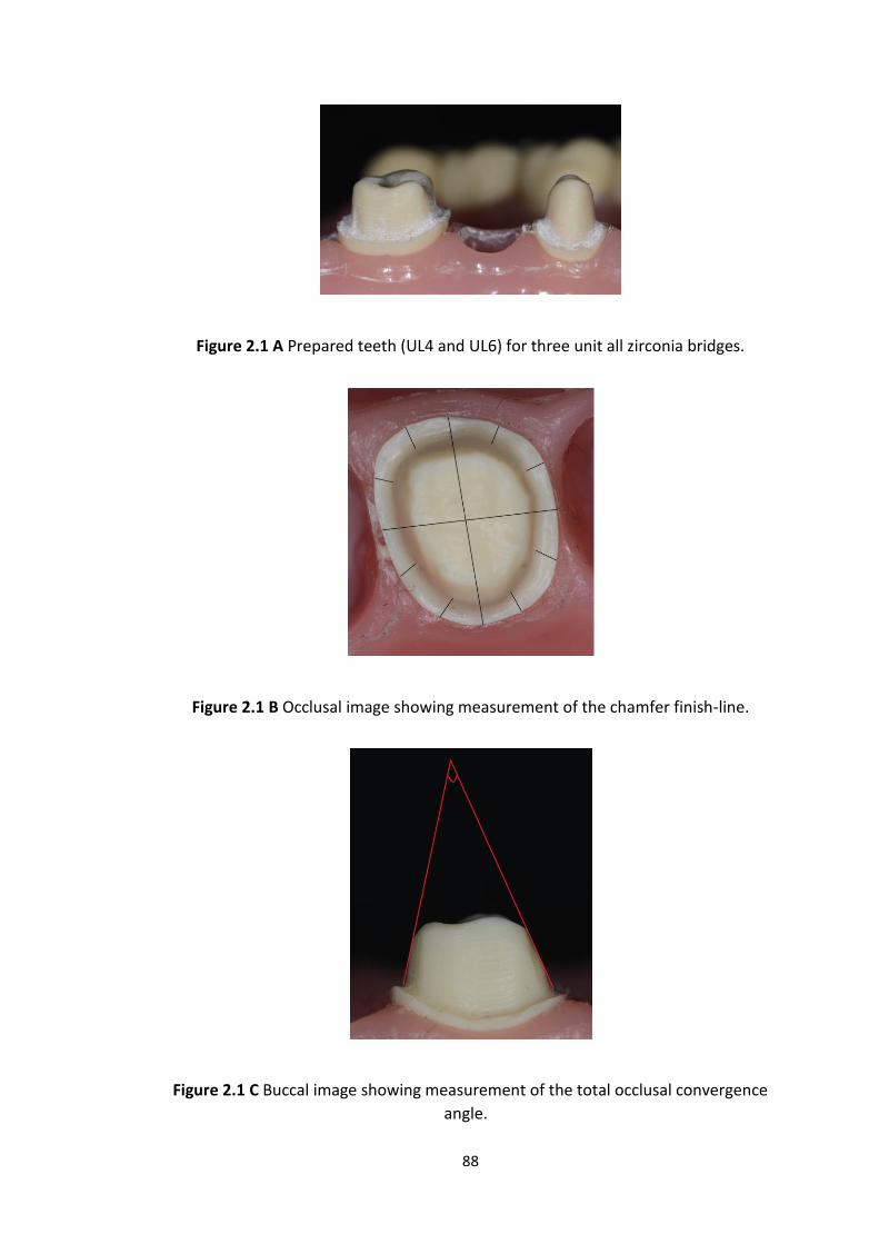
88
Figure 2.1 A Prepared teeth (UL4 and UL6) for three unit all zirconia bridges.
Figure 2.1 B Occlusal image showing measurement of the chamfer finish-line.
Figure 2.1 C Buccal image showing measurement of the total occlusal convergence
angle.
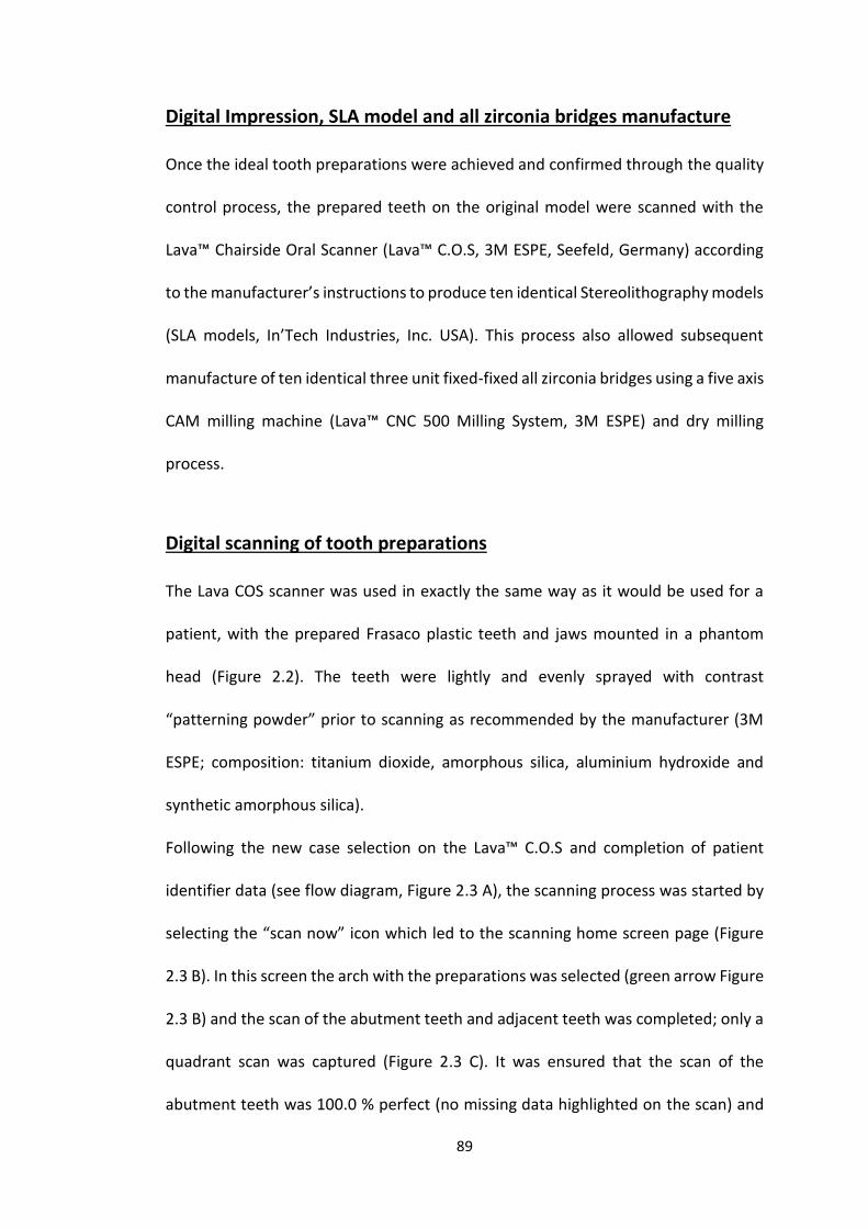
89
Digital Impression, SLA model and all zirconia bridges manufacture
Once the ideal tooth preparations were achieved and confirmed through the quality
control process, the prepared teeth on the original model were scanned with the
Lava™ Chairside Oral Scanner (Lava™ C.O.S, 3M ESPE, Seefeld, Germany) according
to the manufacturer’s instructions to produce ten identical Stereolithography models
(SLA models, In’Tech Industries, Inc. USA). This process also allowed subsequent
manufacture of ten identical three unit fixed-fixed all zirconia bridges using a five axis
CAM milling machine (Lava™ CNC 500 Milling System, 3M ESPE) and dry milling
process.
Digital scanning of tooth preparations
The Lava COS scanner was used in exactly the same way as it would be used for a
patient, with the prepared Frasaco plastic teeth and jaws mounted in a phantom
head (Figure 2.2). The teeth were lightly and evenly sprayed with contrast
“patterning powder” prior to scanning as recommended by the manufacturer (3M
ESPE; composition: titanium dioxide, amorphous silica, aluminium hydroxide and
synthetic amorphous silica).
Following the new case selection on the Lava™ C.O.S and completion of patient
identifier data (see flow diagram, Figure 2.3 A), the scanning process was started by
selecting the “scan now” icon which led to the scanning home screen page (Figure
2.3 B). In this screen the arch with the preparations was selected (green arrow Figure
2.3 B) and the scan of the abutment teeth and adjacent teeth was completed; only a
quadrant scan was captured (Figure 2.3 C). It was ensured that the scan of the
abutment teeth was 100.0 % perfect (no missing data highlighted on the scan) and
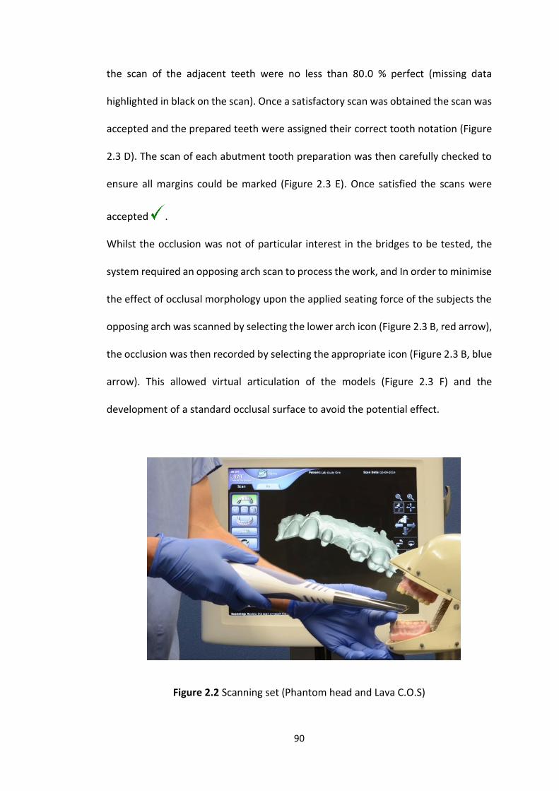
90
the scan of the adjacent teeth were no less than 80.0 % perfect (missing data
highlighted in black on the scan). Once a satisfactory scan was obtained the scan was
accepted and the prepared teeth were assigned their correct tooth notation (Figure
2.3 D). The scan of each abutment tooth preparation was then carefully checked to
ensure all margins could be marked (Figure 2.3 E). Once satisfied the scans were
accepted .
Whilst the occlusion was not of particular interest in the bridges to be tested, the
system required an opposing arch scan to process the work, and In order to minimise
the effect of occlusal morphology upon the applied seating force of the subjects the
opposing arch was scanned by selecting the lower arch icon (Figure 2.3 B, red arrow),
the occlusion was then recorded by selecting the appropriate icon (Figure 2.3 B, blue
arrow). This allowed virtual articulation of the models (Figure 2.3 F) and the
development of a standard occlusal surface to avoid the potential effect.
Figure 2.2 Scanning set (Phantom head and Lava C.O.S)
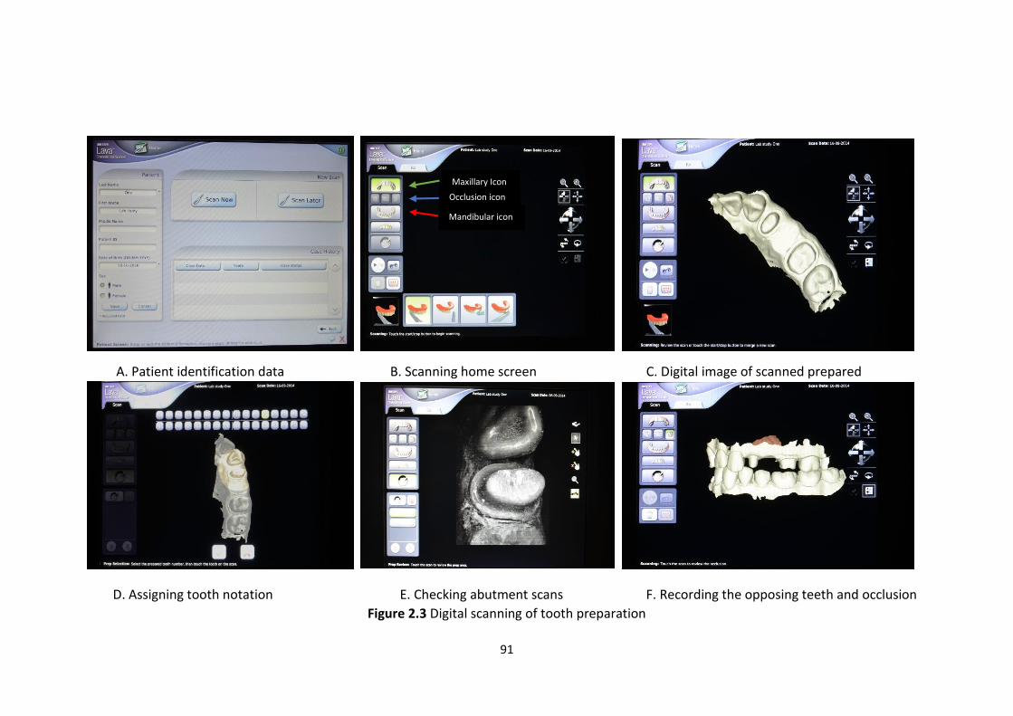
91
A. Patient identification data B. Scanning home screen C. Digital image of scanned prepared
D. Assigning tooth notation E. Checking abutment scans F. Recording the opposing teeth and occlusion
Figure 2.3 Digital scanning of tooth preparation
Occlusion icon
scanning icon
Mandibular icon
Maxillary Icon
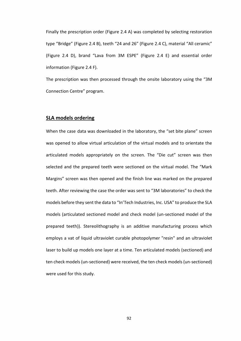
92
Finally the prescription order (Figure 2.4 A) was completed by selecting restoration
type “Bridge” (Figure 2.4 B), teeth “24 and 26” (Figure 2.4 C), material “All ceramic”
(Figure 2.4 D), brand “Lava from 3M ESPE” (Figure 2.4 E) and essential order
information (Figure 2.4 F).
The prescription was then processed through the onsite laboratory using the “3M
Connection Centre” program.
SLA models ordering
When the case data was downloaded in the laboratory, the “set bite plane” screen
was opened to allow virtual articulation of the virtual models and to orientate the
articulated models appropriately on the screen. The “Die cut” screen was then
selected and the prepared teeth were sectioned on the virtual model. The “Mark
Margins” screen was then opened and the finish line was marked on the prepared
teeth. After reviewing the case the order was sent to “3M laboratories” to check the
models before they sent the data to “In’Tech Industries, Inc. USA” to produce the SLA
models (articulated sectioned model and check model (un-sectioned model of the
prepared teeth)). Stereolithography is an additive manufacturing process which
employs a vat of liquid ultraviolet curable photopolymer "resin" and an ultraviolet
laser to build up models one layer at a time. Ten articulated models (sectioned) and
ten check models (un-sectioned) were received, the ten check models (un-sectioned)
were used for this study.
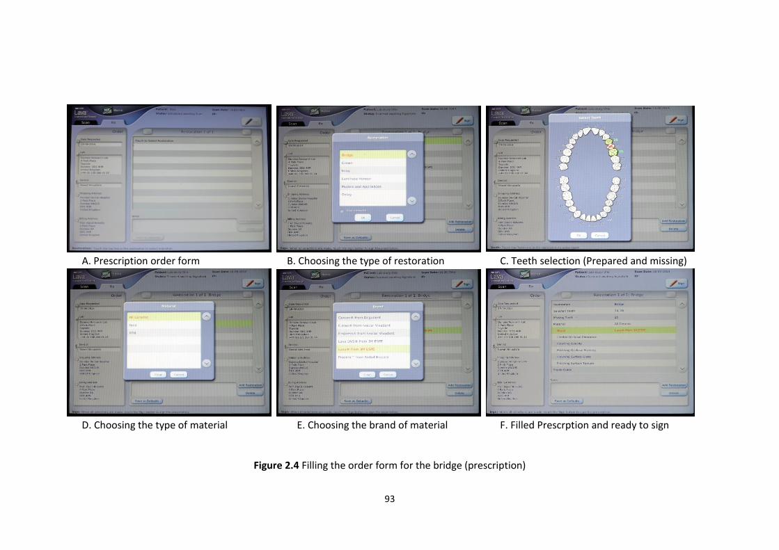
93
A. Prescription order form B. Choosing the type of restoration C. Teeth selection (Prepared and missing)
D. Choosing the type of material E. Choosing the brand of material F. Filled Prescrption and ready to sign
Figure 2.4 Filling the order form for the bridge (prescription)

94
Bridge designing
A new order or prescription should be created for each new zirconia bridge. Lava
Design Client software by Dental Wings Operating System (DWOS) was used to design
the zirconia bridges from the intra-oral digital scan data. The first stage of creating
the order was to initially identify the type of restoration required. For this, under the
order creation icon the 3M Lava order icon was selected (Figure 2.5 A). The prepared
teeth were then individually selected on the dental diagram (UL4 and UL6) (Figure
2.5 B). For each abutment tooth under the “Prosthesis family” drop down box the
“Crowns” item was selected (Figure 2.5 C). Under the “Material” drop box “Lava
zirconia” was selected (Figure 2.5 D), and under the “Prosthesis sub type” the item
“full crown” was chosen (Figure 2.5 E). For the pontic tooth UL5 was selected from
the dental diagram, from the “Prosthetic family” drop down box “Pontics” was
chosen, from the “Material” drop down box “Lava zirconia” was selected and from
“Prosthetic sub type” drop down box “Full pontics” was chosen. The three teeth were
then selected from the dental diagram and the “Create bridge” icon chosen, this
allowed the software to connect all the components and finalize the bridge order
(Figure 2.5 F).
Once the type of bridge required had been entered, the next stage of the process
was to relate the design components of the bridge to the scanned data (virtual model
(Figure 2.5 G)). On the virtual model the preparation margins (finish-line) were then
identified using the software “Automatic detection of the margin” and adjusted
manually with the cursor as necessary (Figure 2.5 H). The axis of insertion was then
chosen to allow the software to calculate this for both abutment teeth (Figure 2.5 I).
After accepting the axis of insertion the bridge design was completed in the CAD

95
station page (Figure 2.5 J). In this page the cusps, contact points and connectors were
adjusted and the final bridge was checked and accepted (Figure 2.5 K). The die-spacer
is automatically calculated by the CAD software (die spacer 0.095mm extra vertical
(occlusal), 0.075 mm extra horizontal (buccal, mesial, distal and lingual), and 0.025
mm on the margin) and minimum coping thickness 0.5 mm. The bridge data was then
routed to Lava Design Software 7 (Figure 2.5 L) to assign the virtual bridge to the
zirconia block to be used in the milling machine.
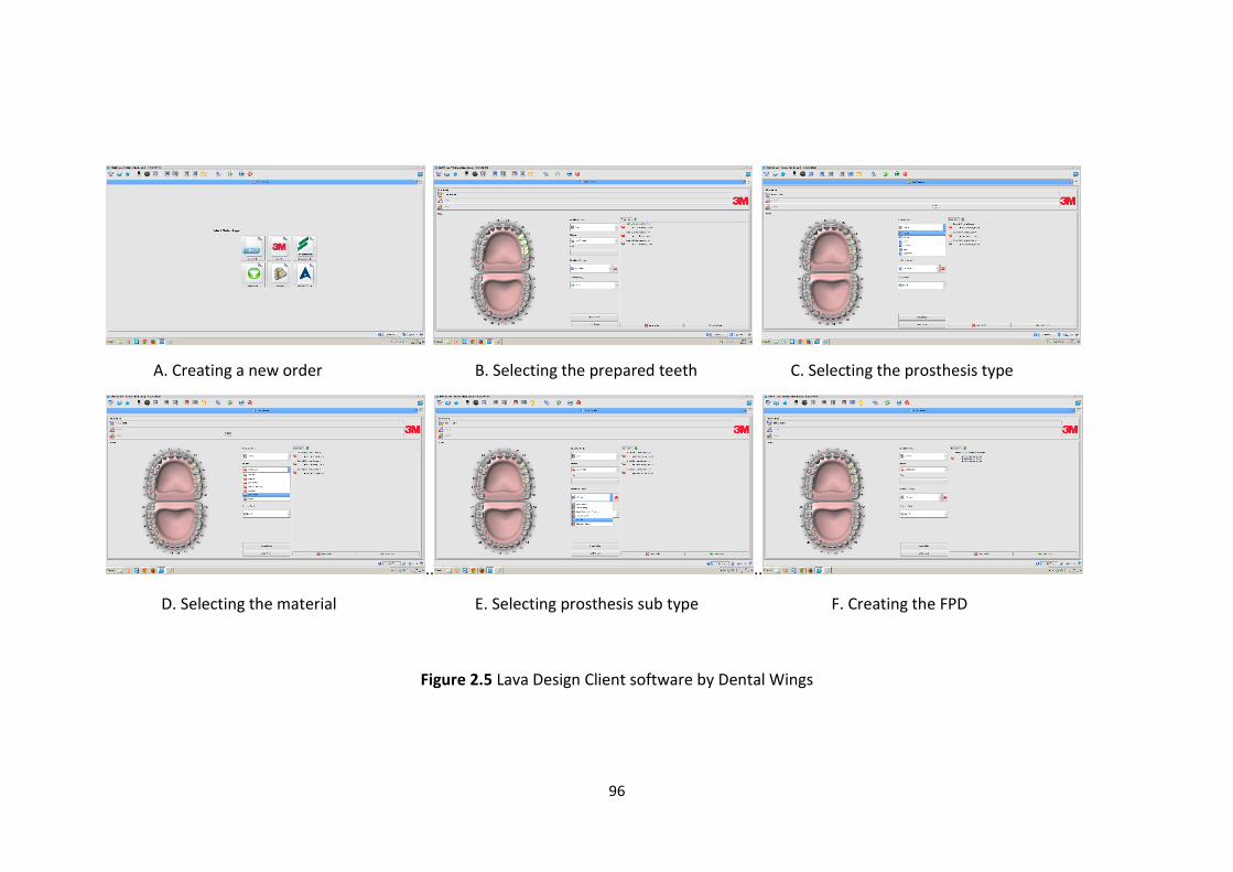
96
A. Creating a new order B. Selecting the prepared teeth C. Selecting the prosthesis type
.. ..
D. Selecting the material E. Selecting prosthesis sub type F. Creating the FPD
Figure 2.5 Lava Design Client software by Dental Wings
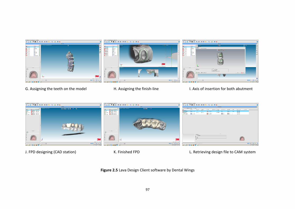
97
G. Assigning the teeth on the model H. Assigning the finish-line I. Axis of insertion for both abutment
J. FPD designing (CAD station) K. Finished FPD L. Retrieving design file to CAM system
Figure 2.5 Lava Design Client software by Dental Wings
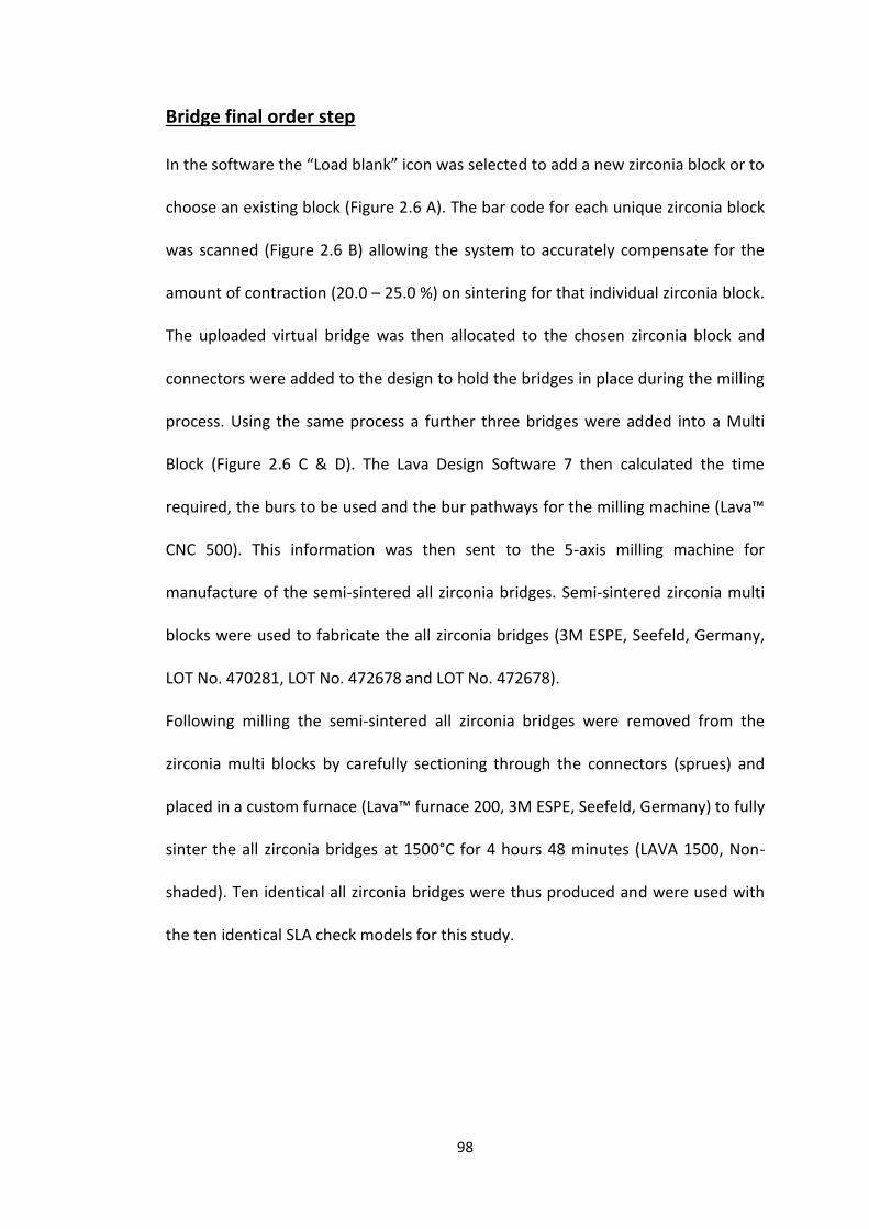
98
Bridge final order step
In the software the “Load blank” icon was selected to add a new zirconia block or to
choose an existing block (Figure 2.6 A). The bar code for each unique zirconia block
was scanned (Figure 2.6 B) allowing the system to accurately compensate for the
amount of contraction (20.0 – 25.0 %) on sintering for that individual zirconia block.
The uploaded virtual bridge was then allocated to the chosen zirconia block and
connectors were added to the design to hold the bridges in place during the milling
process. Using the same process a further three bridges were added into a Multi
Block (Figure 2.6 C & D). The Lava Design Software 7 then calculated the time
required, the burs to be used and the bur pathways for the milling machine (Lava™
CNC 500). This information was then sent to the 5-axis milling machine for
manufacture of the semi-sintered all zirconia bridges. Semi-sintered zirconia multi
blocks were used to fabricate the all zirconia bridges (3M ESPE, Seefeld, Germany,
LOT No. 470281, LOT No. 472678 and LOT No. 472678).
Following milling the semi-sintered all zirconia bridges were removed from the
zirconia multi blocks by carefully sectioning through the connectors (sprues) and
placed in a custom furnace (Lava™ furnace 200, 3M ESPE, Seefeld, Germany) to fully
sinter the all zirconia bridges at 1500°C for 4 hours 48 minutes (LAVA 1500, Non-
shaded). Ten identical all zirconia bridges were thus produced and were used with
the ten identical SLA check models for this study.
99
A. Scanning the bar code B. Multi zirconia block
C. Virtually loading the bridge D. Loading four bridges in the block
Figure 2.6. Loading the virtual bridges to the zirconia blocks
100
Force applied during cementation procedure
Ten practitioners were recruited for this study and allocated one SLA model and one
all zirconia bridge each. All practitioners were qualified dentists: six were consultants
in restorative dentistry and four were postgraduate students in restorative dentistry,
all having at least five years post graduate experience. RelyX™ Unicem 2 Clicker™ (3M
ESPE, Seefeld, Germany, LOT No. 491286) self-adhesive Universal Resin Cement was
used as the luting cement. So that repeated cementations of the same bridge could
be carried out on different occasions, only the base paste of this material was used
to prevent setting of the cement.
For each cementation procedure the internal aspect of the two all zirconia bridge
retainers were coated with the base cement and the practitioners were instructed to
seat the bridge with the force that they would use clinically to cement a bridge, using
two fingers, one over each retainer (as previously determined in a pilot study of ten
dentists’ cementation technique) for two minutes. To measure the cementation
force (Newton), the SLA model was placed on a universal testing machine (Instron®,
model 4469) table while the all zirconia bridges were cemented by the dentists. A
stop watch was mounted on the Instron machine alongside its control panel force
display. A continuous recording video camera captured the force and time for each
cementation procedure: cementation force was recorded at 10 second intervals for
two minutes.
Each examiner performed the seating procedure six times over a two week period,
blind to the cementation force and previous recordings: three times each week on
alternate days. After each cementation procedure the base cement was thoroughly
cleaned from the fit surface of the bridge and from the prepared teeth by brushing
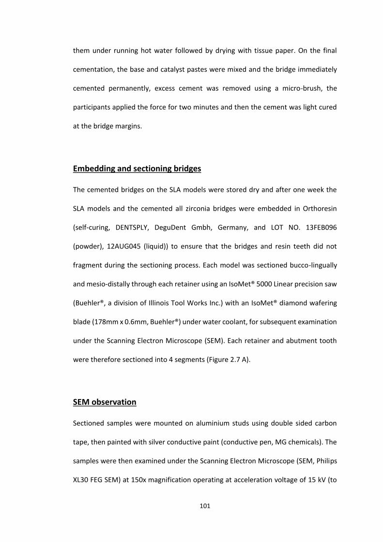
101
them under running hot water followed by drying with tissue paper. On the final
cementation, the base and catalyst pastes were mixed and the bridge immediately
cemented permanently, excess cement was removed using a micro-brush, the
participants applied the force for two minutes and then the cement was light cured
at the bridge margins.
Embedding and sectioning bridges
The cemented bridges on the SLA models were stored dry and after one week the
SLA models and the cemented all zirconia bridges were embedded in Orthoresin
(self-curing, DENTSPLY, DeguDent Gmbh, Germany, and LOT NO. 13FEB096
(powder), 12AUG045 (liquid)) to ensure that the bridges and resin teeth did not
fragment during the sectioning process. Each model was sectioned bucco-lingually
and mesio-distally through each retainer using an IsoMet® 5000 Linear precision saw
(Buehler®, a division of Illinois Tool Works Inc.) with an IsoMet® diamond wafering
blade (178mm x 0.6mm, Buehler®) under water coolant, for subsequent examination
under the Scanning Electron Microscope (SEM). Each retainer and abutment tooth
were therefore sectioned into 4 segments (Figure 2.7 A).
SEM observation
Sectioned samples were mounted on aluminium studs using double sided carbon
tape, then painted with silver conductive paint (conductive pen, MG chemicals). The
samples were then examined under the Scanning Electron Microscope (SEM, Philips
XL30 FEG SEM) at 150x magnification operating at acceleration voltage of 15 kV (to
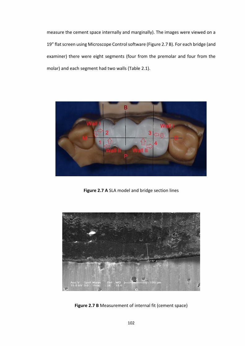
102
measure the cement space internally and marginally). The images were viewed on a
19” flat screen using Microscope Control software (Figure 2.7 B). For each bridge (and
examiner) there were eight segments (four from the premolar and four from the
molar) and each segment had two walls (Table 2.1).
Figure 2.7 A SLA model and bridge section lines
Figure 2.7 B Measurement of internal fit (cement space)
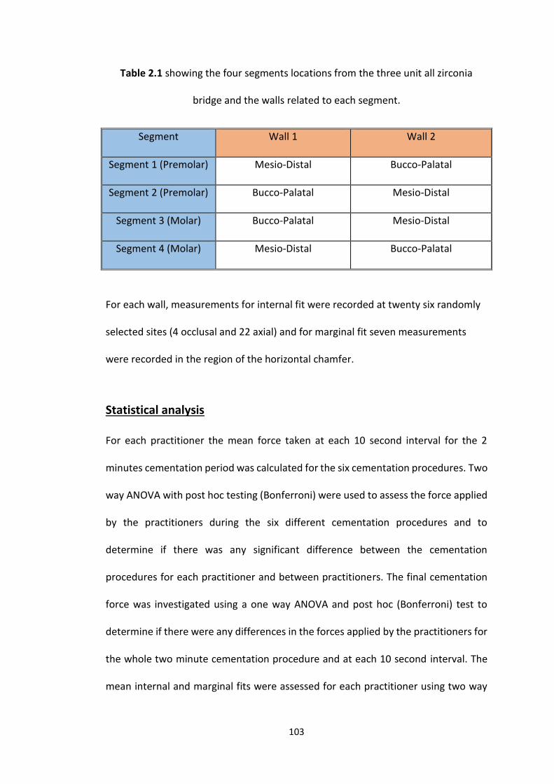
103
Table 2.1 showing the four segments locations from the three unit all zirconia
bridge and the walls related to each segment.
Segment Wall 1 Wall 2
Segment 1 (Premolar) Mesio-Distal Bucco-Palatal
Segment 2 (Premolar) Bucco-Palatal Mesio-Distal
Segment 3 (Molar) Bucco-Palatal Mesio-Distal
Segment 4 (Molar) Mesio-Distal Bucco-Palatal
For each wall, measurements for internal fit were recorded at twenty six randomly
selected sites (4 occlusal and 22 axial) and for marginal fit seven measurements
were recorded in the region of the horizontal chamfer.
Statistical analysis
For each practitioner the mean force taken at each 10 second interval for the 2
minutes cementation period was calculated for the six cementation procedures. Two
way ANOVA with post hoc testing (Bonferroni) were used to assess the force applied
by the practitioners during the six different cementation procedures and to
determine if there was any significant difference between the cementation
procedures for each practitioner and between practitioners. The final cementation
force was investigated using a one way ANOVA and post hoc (Bonferroni) test to
determine if there were any differences in the forces applied by the practitioners for
the whole two minute cementation procedure and at each 10 second interval. The
mean internal and marginal fits were assessed for each practitioner using two way
104
ANOVA and post hoc (Bonferroni) to determine if there was any differences between
them (IBM® SPSS® 21). The relationship between the mean internal and mean
marginal fits with the final cementation force applied was investigated using the
Pearson Correlation co-efficient.
2.4 Results
Force
All six cementation procedures
Analysis of the force applied at every 10 second interval over the two minute
cementation procedure for all 10 practitioners on the six separate occasions, showed
that the mean force applied was 27.2 N (min 8.0 N, max 88.0 N, SD ± 7.9).
For each practitioner, two way ANOVA showed that there was no statistically
significant difference between the cementation forces applied in every 10 seconds
over the two minutes in the six cementation procedures (p = 0.19). However there
was a significant difference in the mean force applied over the six, two minute
cementation procedures between the practitioners (p ≤ 0.001). Post hoc test
(Bonferroni) showed that for most paired comparisons between practitioners there
was a statistical significant difference in force applied )Table 2.2).
Observation of the cementation force overtime showed that individual practitioners
consistently applied higher forces during the first 20 second period. Two way ANOVA
showed that in the first 20 second period all ten practitioners applied different
cementation forces (p ≤ 0.05) However, the force applied over the remaining time
(100 s) periods was less variable between practitioners with post hoc test
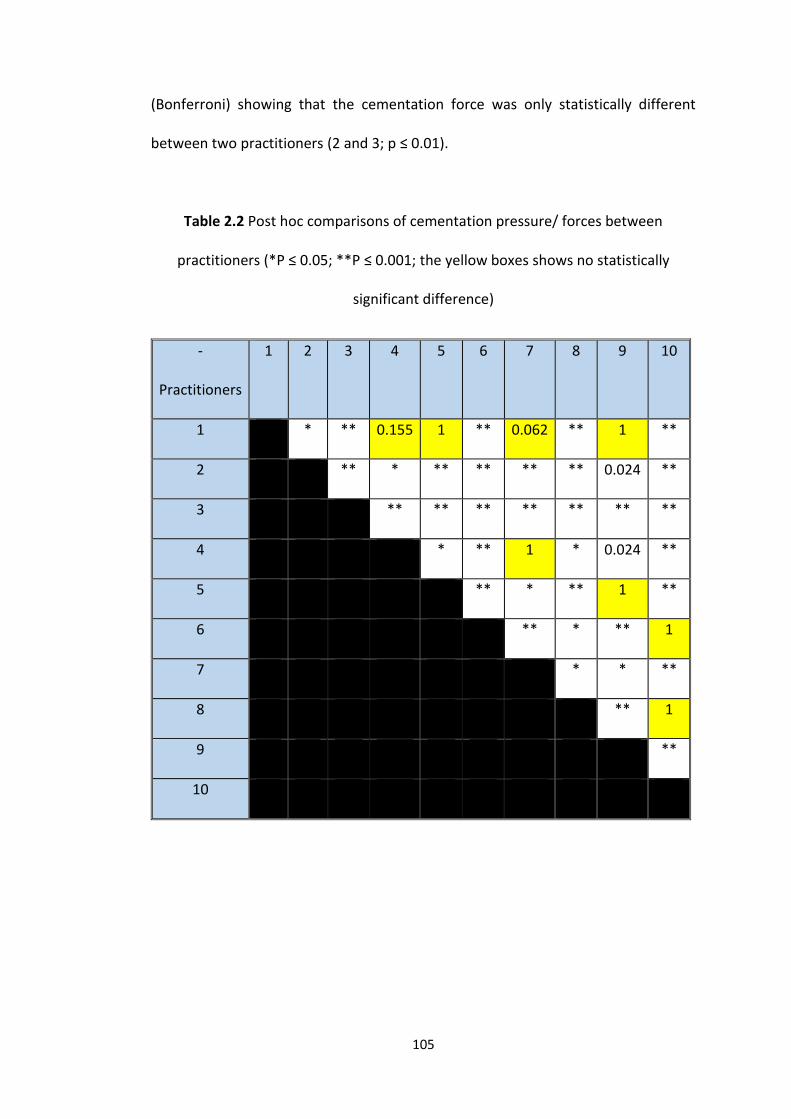
105
(Bonferroni) showing that the cementation force was only statistically different
between two practitioners (2 and 3; p ≤ 0.01).
Table 2.2 Post hoc comparisons of cementation pressure/ forces between
practitioners (*P ≤ 0.05; **P ≤ 0.001; the yellow boxes shows no statistically
significant difference)
-
Practitioners
1 2 3 4 5 6 7 8 9 10
1 * ** 0.155 1 ** 0.062 ** 1 **
2 ** * ** ** ** ** 0.024 **
3 ** ** ** ** ** ** **
4 * ** 1 * 0.024 **
5 ** * ** 1 **
6 ** * ** 1
7 * * **
8 ** 1
9 **
10
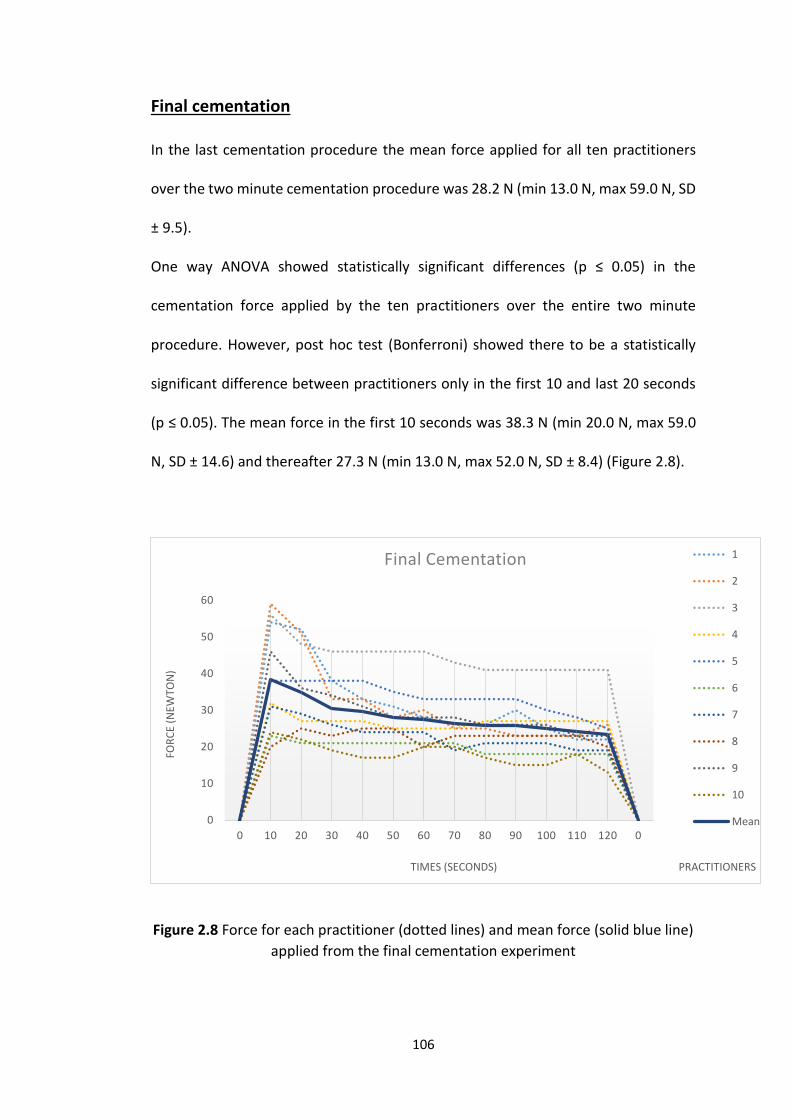
106
Final cementation
In the last cementation procedure the mean force applied for all ten practitioners
over the two minute cementation procedure was 28.2 N (min 13.0 N, max 59.0 N, SD
± 9.5).
One way ANOVA showed statistically significant differences (p ≤ 0.05) in the
cementation force applied by the ten practitioners over the entire two minute
procedure. However, post hoc test (Bonferroni) showed there to be a statistically
significant difference between practitioners only in the first 10 and last 20 seconds
(p ≤ 0.05). The mean force in the first 10 seconds was 38.3 N (min 20.0 N, max 59.0
N, SD ± 14.6) and thereafter 27.3 N (min 13.0 N, max 52.0 N, SD ± 8.4) (Figure 2.8).
Figure 2.8 Force for each practitioner (dotted lines) and mean force (solid blue line)
applied from the final cementation experiment
0
10
20
30
40
50
60
0 10 20 30 40 50 60 70 80 90 100 110 120 0
FOR
CE
(NEW
TON
)
TIMES (SECONDS) PRACTITIONERS
Final Cementation 1
2
3
4
5
6
7
8
9
10
Mean
107
Internal and marginal fit
Analysis of the readings of internal fit results for both abutment/retainers and all
practitioners showed a mean gap of 90.4 µm ± 0.6 (min 79.4 µm, max 106.7 µm). Two
way ANOVA showed a statistically significant difference in internal fit between the
practitioner’s cemented FPDs (p ≤ 0.05); post hoc (Bonferroni) test showed that the
results of practitioner 3 only had significant difference from the other practitioners,
where all the other practitioners showed no significant difference in internal fit.
Where marginal fit was concerned (mean 28.4 µm ± 0.2, min 24.1 µm and max 31.5
µm) there was no statistically significant difference between the practitioners (p =
0.714).
Analysis of the marginal gap of the mesial aspects of the premolar and distal of the
molar teeth were examined statistically (two way ANOVA) to check if there was any
impact which may arise from a different force being applied by each finger on
different abutments, the results showed no significant difference (p = 0.897).
Force and fit
Comparison of the mean internal fit and marginal fit with the mean force applied for
all participants showed that there was a moderate to strong inverse relationship
between force applied and internal fit (Pearson Correlation Coefficient = - 0.69; P ≤
0.05) and no statistically significant relationship to marginal fit (Pearson Correlation
Coefficient = - 0.28; P = 0.16). One examiner stood out in applying a greater force for
the duration of the cementation; elimination of this examiner from the analysis
108
resulted in no statistically significant relationship in the cementation force and
internal or marginal fit.
2.5 Discussion
The two previous studies that have investigated the cementation force used by
dentists in seating indirect restorations have focussed on single unit crowns. These
studies have shown that the forces generally applied ranged from 12.0 to 67.0 N
(Black and Amoore, 1993, Mustafa et al., 2010). It is possible that when cementing
more substantial restorations involving two or more teeth and having a longer span,
the dentist could apply different forces, however, this study showed that the forces
applied are, in general, comparable, in the order of magnitude of 8.0 to 88.0 N.
The digital files produced by the intraoral scanner (Lava COS) in this study were used
to produce multiple, identical SLA models and corresponding bridges. It is important
that the models were identical so that any differences in fit was as a result of the
dentists’ cementation force and not a difference in model dimensions. In 2014
Patzelt et al. conducted a study to compare multiple SLA models created with two
intra-oral scanning systems (CEREC AC with Bluecam and the Lava™ C.O.S) with that
of milled models also produced from compatible intra-oral scans (produced by iTero,
Align Technology, San Jose, California). Using a laboratory reference scanner as a gold
standard it was found that the models produced with all three systems were clinically
fit for purpose, however the SLA models were more accurate, with the models
produced using the Lava™ C.O.S having the highest degree of precision and
109
reproducibility (Patzelt et al., 2014a). These results therefore gave confidence in the
use of the Lava™ C.O.S SLA models in this and subsequent studies in this thesis.
In the normal manufacture of SLA models the manufacturer provides articulated
models with sectioned dies and un-sectioned (check) models. The sectioned models
facilitate the manufacture of restorations by enabling the individual master die to be
removed from the arch, so that additions and adjustments of veneering ceramic can
be carried out more easily. However, the gap created in the sectioned models allows
some movement of the abutment teeth, which could affect the internal and marginal
fit when different cementation forces were used, as the dies could move to achieve
the optimum fit. As such in the study only the un-sectioned check models were used
to avoid the problem.
RelyX Unicem cement was used in this study as the luting cement, as it is the cement
recommended by the manufacturer of the CAD CAM system and that used in
previous studies hence allowing comparisons to be made (Scotti et al., 2011, Son et
al., 2012, Ahrberg et al., 2015). Although Rely X Unicem is a dual cured cement, in
the final cementation in this study it was light cured to ensure that the cement had
set at the marginal gap, duplicating the clinical procedure. The manufacturer’s
recommendations for the complete setting time for Rely X Unicem is either 6 minutes
for self-cure or up to 3 minutes for light-cure (RelyX™ Unicem Clicker™ 3M ESPE,
cementation technique). In the real clinical situation it is very difficult and painful (for
patient and dentist) to keep a seating force for more than two minutes continually
and Figure 2.8 shows that fatigue probably explains why the seating force gradually
110
decreases with time. Hence, in this study, a two minute seating force and then light
cure was considered to realistically represent what happens clinically.
The force application in the clinic is sometimes achieved by the dentists asking
patients to bite on a cotton roll placed between the restoration and the opposing
teeth to finally seat the restoration (Wassell et al., 2002a, Silvey and Myers, 1977).
This could pose a problem in longer span bridges in that an equal and balanced force
over each abutment tooth is required and may not be achieved, especially posteriorly
in relation to the hinge movement in opening and closing, when asking patients to
bite to seat the restoration. It has also been shown that patients can achieve a much
greater maximum bite force of 350 to 850 N between posterior teeth (Bates et al.,
1975, Gibbs et al., 1986) and 120 to 350 N between anterior teeth (Helkimo et al.,
1977, Tortopidis et al., 1998), than was achieved by dentists cementing restorations
in this study and previous studies (Black and Amoore, 1993, Mustafa et al., 2010).
Not only is maximum bite force influenced by the position in the arch, but there are
other different factors that can affect the bite force:
Gender may have an influence on the bite force, studies have shown that males exert
a higher maximum bite force compared to females (Helkimo et al., 1977, Shinogaya
et al., 2001, Koç et al., 2011).
The maximum bite force is reached at the age of 20 to 40 years, and then starts to
decline (Kiliaridis et al., 1993, Bakke, 2006, Palinkas et al., 2010).
Craniofacial variables. Patients with different facial types (short, average and long
face) produce different bite forces with the highest force applied by people with
short faces, followed by people with average faces and the lowest recorded from

111
people with long faces (Ringqvist, 1973, Kiliaridis et al., 1993, Waltimo et al., 1994,
Bonakdarchian et al., 2009).
The number of teeth present plays another role on the strength of the bite force.
Patients with a full dentition demonstrate the highest maximum bite force, followed
by those with bridges, then removable partial dentures and finally people with
complete dentures showed the lowest maximum bite force (Helkimo et al., 1977,
Bakke et al., 1990).
Patients with poor periodontal condition may have lower levels of maximum bite
force (Williams et al., 1987, Alkan et al., 2006). However, some studies have shown
that the effect of periodontal health has a negligible effect (Kleinfelder and Ludwig,
2002, Morita et al., 2003).
Temporo-mandibular disorders that relate to any pain or disturbance to the
masticatory system and masticatory muscle pain can limit or lower the maximum bite
force of a person (Kogawa et al., 2006, Pizolato et al., 2007).
It is also unknown how sustained the bite force is over time when used to cement
restorations. As such the practice of asking patients to use occlusal force to seat
restorations should be discouraged due to its uncontrolled nature.
In studies which have investigated the retention of cemented crowns, sustained
uniform seating forces have been applied to seat and secure the restorations. The
forces used have ranged from 50.0 N to 200.0 N (Proussaefs, 2004, Palacios et al.,
2006, Johnson et al., 2009). The duration over which seating force is applied when
cementing a dental restoration could also have an impact on the flow of cements,
the final cement film thickness, fit and retention of a restoration. The effect of
112
applying a constant seating force of 100.0 N over a five second and three minutes
period of time has been investigated when Panavia F was used with and without
Clearfil Protect Bond. The prolonged application of constant seating force and the
use of a hydrophobic light-cured adhesive (Clearfil Protect Bond) both resulted in
improved bond strength of resin blocks cemented on natural teeth (Chieffi et al.,
2007).
In two publications that have examined the fit of indirect restorations it has been
stated that 50 measurements per restoration are required to fully appreciate the
accuracy of fit (Groten et al., 2000, Nawafleh et al., 2013). It has also been
recommended that the number of measurements should be related to the sample
size: however for most studies if there were around 30 specimens then
approximately 20 to 25 measurements per crown or retainer would be acceptable
(Nawafleh et al., 2013). Hence in this study readings were recorded at 33 randomly
selected sites for each sample wall, (26 internal (4 occlusal and 22 axial) and 7
marginal) making a total of 66 readings for each retainer-abutment interface. The
readings for internal fit in this study were greatest occlusally followed by the axial
walls, with the marginal fit having the closest adaptation. The actual internal and
marginal fit of the restorations, whilst closely reflecting the default die spacer
dimensions used when designing the restoration in the CAD software, did increase
slightly in all areas: CAD CAM default die spacer = 95.0 µm occlusal, 75.0 µm axial and
25.0 µm marginal compared with actual mean fit of 90.4 µm internal (occlusal and
axial combined) and 28.4 µm marginal.
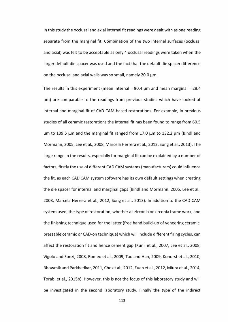
113
In this study the occlusal and axial internal fit readings were dealt with as one reading
separate from the marginal fit. Combination of the two internal surfaces (occlusal
and axial) was felt to be acceptable as only 4 occlusal readings were taken when the
larger default die spacer was used and the fact that the default die spacer difference
on the occlusal and axial walls was so small, namely 20.0 µm.
The results in this experiment (mean internal = 90.4 µm and mean marginal = 28.4
µm) are comparable to the readings from previous studies which have looked at
internal and marginal fit of CAD CAM based restorations. For example, in previous
studies of all ceramic restorations the internal fit has been found to range from 60.5
µm to 109.5 µm and the marginal fit ranged from 17.0 µm to 132.2 µm (Bindl and
Mormann, 2005, Lee et al., 2008, Marcela Herrera et al., 2012, Song et al., 2013). The
large range in the results, especially for marginal fit can be explained by a number of
factors, firstly the use of different CAD CAM systems (manufacturers) could influence
the fit, as each CAD CAM system software has its own default settings when creating
the die spacer for internal and marginal gaps (Bindl and Mormann, 2005, Lee et al.,
2008, Marcela Herrera et al., 2012, Song et al., 2013). In addition to the CAD CAM
system used, the type of restoration, whether all zirconia or zirconia frame work, and
the finishing technique used for the latter (free hand build-up of veneering ceramic,
pressable ceramic or CAD-on technique) which will include different firing cycles, can
affect the restoration fit and hence cement gap (Kunii et al., 2007, Lee et al., 2008,
Vigolo and Fonzi, 2008, Romeo et al., 2009, Tao and Han, 2009, Kohorst et al., 2010,
Bhowmik and Parkhedkar, 2011, Cho et al., 2012, Euan et al., 2012, Miura et al., 2014,
Torabi et al., 2015b). However, this is not the focus of this laboratory study and will
be investigated in the second laboratory study. Finally the type of the indirect
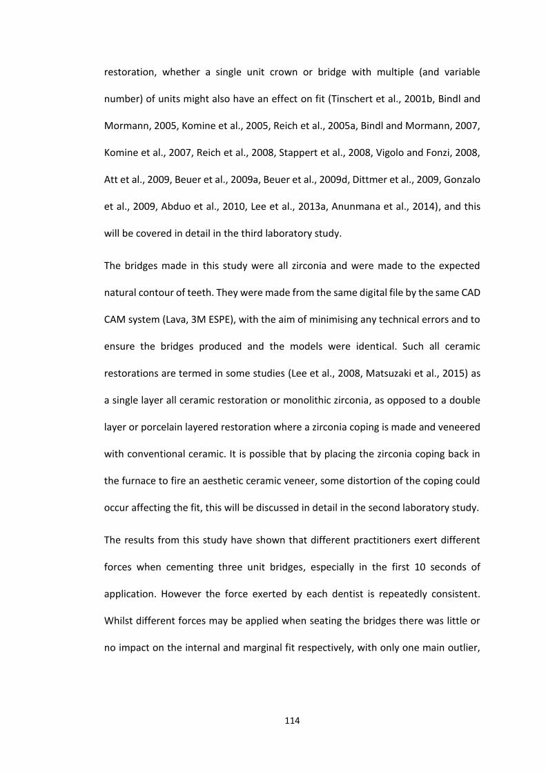
114
restoration, whether a single unit crown or bridge with multiple (and variable
number) of units might also have an effect on fit (Tinschert et al., 2001b, Bindl and
Mormann, 2005, Komine et al., 2005, Reich et al., 2005a, Bindl and Mormann, 2007,
Komine et al., 2007, Reich et al., 2008, Stappert et al., 2008, Vigolo and Fonzi, 2008,
Att et al., 2009, Beuer et al., 2009a, Beuer et al., 2009d, Dittmer et al., 2009, Gonzalo
et al., 2009, Abduo et al., 2010, Lee et al., 2013a, Anunmana et al., 2014), and this
will be covered in detail in the third laboratory study.
The bridges made in this study were all zirconia and were made to the expected
natural contour of teeth. They were made from the same digital file by the same CAD
CAM system (Lava, 3M ESPE), with the aim of minimising any technical errors and to
ensure the bridges produced and the models were identical. Such all ceramic
restorations are termed in some studies (Lee et al., 2008, Matsuzaki et al., 2015) as
a single layer all ceramic restoration or monolithic zirconia, as opposed to a double
layer or porcelain layered restoration where a zirconia coping is made and veneered
with conventional ceramic. It is possible that by placing the zirconia coping back in
the furnace to fire an aesthetic ceramic veneer, some distortion of the coping could
occur affecting the fit, this will be discussed in detail in the second laboratory study.
The results from this study have shown that different practitioners exert different
forces when cementing three unit bridges, especially in the first 10 seconds of
application. However the force exerted by each dentist is repeatedly consistent.
Whilst different forces may be applied when seating the bridges there was little or
no impact on the internal and marginal fit respectively, with only one main outlier,
115
practitioner 3, who exerted a sustained higher force throughout but having a bridge
of similar marginal fit.
It could be argued that the force applied in such an artificial environment as in this
study, may be different to that applied intra-orally. But since the examiners used a
range of forces with no impact on fit this is unlikely to be a problem clinically.
2.6 Conclusions
Within the limitations of this study, the following conclusion can be drawn:
1. Dentist apply different forces when cementing bridges.
2. Initial force is the highest and it starts to plateau after 30 Sec.
3. In the final cementation experiment the mean forces applied were between 13 N
and 59 N, leading to clinically acceptable marginal and internal fit of the final
cemented all zirconia three unit bridges.
4. In summary, different seating forces applied to the bridges during cementation
do not influence the fit of the restoration.
116
Chapter 3
Laboratory study 2
The effect of firing cycles and
zirconia thickness on the internal
and marginal fit of zirconia bridges

117
Laboratory study 2
The effect of firing cycles and zirconia thickness on the
internal and marginal fit of zirconia bridges
3.1 Introduction
Metal ceramic indirect dental restorations were the restoration of choice for many
years, mainly due to their long history of use and predictable outcomes (Sundh et al.,
2005). Whilst satisfactory aesthetic results can be obtained with metal ceramic
crowns, heavier tooth reduction is required to provide sufficient space for the metal
coping, opaquing and veneering ceramics. Even when this is carried out, problems
can arise in poor translucency and lack of a natural appearance. With the high
demand for aesthetic restorations, all ceramic based restorations were introduced
and have become widely used in contemporary practice due to the improved
aesthetics and strength (Sundh et al., 2005, Manicone et al., 2007) compared to
metal ceramic crowns.
The relatively new concept of manufacturing highly precise indirect dental
restoration using CAD CAM systems has made it possible to produce restorations
from stronger ceramics such as zirconia (Beuer et al., 2008c). Whilst the pre-sintered
zirconia blanks used to mill all zirconia (single layer) CAD CAM restorations are white,
once they have been milled they can be coloured using dyeing liquid (monochrome
118
dip shading) prior to sintering in the furnace. Such all-zirconia restorations are
therefore tooth coloured, but are monochromatic and suffer from a lack of
characterisation. Therefore for restorations in the aesthetic zone the zirconia bridges
are usually made as much thinner copings and frameworks to allow space for
veneering dentine and enamel ceramics (Tuncel et al., 2014). Although, the
manufacturer of CAD CAM systems claim that the dental restorations fabricated
using their systems are of great internal and marginal fit, some studies have shown
that the final restoration fit can be affected due to factors such as the firing cycles
and in particular the additional firing cycle required for the veneering ceramic (Cho
et al., 2012, Euan et al., 2012, Torabi et al., 2015b). The other type of zirconia that
can be used include the translucent zirconia which offers aesthetics to the
restoration because they permit the underlying tooth-coloured substructure to
influence the overall restoration aesthetics. In conclusion they can be used to
construct all-zirconia restorations which provide both aesthetics and strength (Rinke
and Fischer, 2013).
3.2 Aims and objectives
The aims of this in vitro study were to investigate if the firing cycles used for
placement of veneering ceramic over zirconia frameworks had any effect on the
internal and marginal fit of all ceramic bridges, and to determine whether the
different thicknesses of zirconia used in the manufacture of zirconia frame works and
all zirconia bridges could also impact upon internal and marginal fit of the restoration.
119
3.3 Material and Methods
Tooth preparation and quality control
Ideal tooth preparations were achieved for a three unit all zirconia bridge in the first
laboratory study; these were quality controlled for total occlusal convergence and
finish line chamfer depth according to predetermined standards. The same
preparations were used in this laboratory study.
Digital Impression and all zirconia bridge manufacture
The Digital files produced from scanning the prepared teeth in the first laboratory
study were used to produce 45 identical non-sectioned SLA models (Check Models,
In’Tech Industries, Inc. USA) for this study. The data captured by the Lava™ Chairside
Oral Scanner (Lava™ C.O.S, 3M ESPE, Seefeld, Germany) from the first study was also
used to construct 45 zirconia based restorations in this study: 15 all zirconia bridges
and 30 zirconia frameworks (Figure 3.1). The identical all zirconia bridge design
created and steps followed in the first study were used for the order of the all zirconia
bridges (n = 15) in this study; for the 30 zirconia frameworks in this study the same
steps were again followed with the exception that when the zirconia frameworks
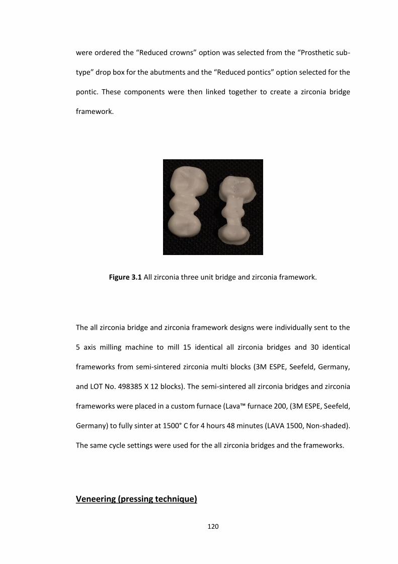
120
were ordered the “Reduced crowns” option was selected from the “Prosthetic sub-
type” drop box for the abutments and the “Reduced pontics” option selected for the
pontic. These components were then linked together to create a zirconia bridge
framework.
Figure 3.1 All zirconia three unit bridge and zirconia framework.
The all zirconia bridge and zirconia framework designs were individually sent to the
5 axis milling machine to mill 15 identical all zirconia bridges and 30 identical
frameworks from semi-sintered zirconia multi blocks (3M ESPE, Seefeld, Germany,
and LOT No. 498385 X 12 blocks). The semi-sintered all zirconia bridges and zirconia
frameworks were placed in a custom furnace (Lava™ furnace 200, (3M ESPE, Seefeld,
Germany) to fully sinter at 1500° C for 4 hours 48 minutes (LAVA 1500, Non-shaded).
The same cycle settings were used for the all zirconia bridges and the frameworks.
Veneering (pressing technique)
121
To investigate whether the veneering process and subsequent firing cycle could have
an effect on the fit of the zirconia based bridges, 15 of the 30 fully sintered zirconia
frameworks were randomly selected to undergo ceramic veneering.
To ensure that all the veneered bridges had a final morphology and identical
dimensions to the all-zirconia bridges, a wax-up technique was used. For this an
addition-cured silicone impression (AFFINIS® putty soft, Coltène, LOT NO. 38620) was
taken in a sectional metallic impression tray, of one of the first all zirconia bridges
made for this study. For each zirconia framework, thereafter, molten pink wax
(modelling wax, ANU TEX, LOT NO. 717308) was poured into the silicone impression
and the zirconia framework gradually inserted until the molten wax reached the
margins of the zirconia framework retainers and the retainer margins were at the
corresponding position of the impression. Once the wax had cooled and solidified the
waxed frameworks were removed from the impression and three 5.0 mm length wax
sprues (3.0 mm diameter, S-U-WACHSDRAHT, LOT 62730019) were attached to each
retainer and pontic (Figure 3.2). Each waxed and sprued framework was then
weighed to ensure consistency (each weighing 1.2g) and to ensure that the correct
number of pressable ceramic ingots were chosen (n = 2).
The sprued waxed frameworks were then mounted on an investment mount and
placed in an investment ring. A graphite free, phosphate bonded investment material
(VITA PM Einbettmasse, 2X100g, LOT NO. 3953346, VITA PM Investment Liquid and
LOT 38650) was then mixed under vacuum according to the manufacturer’s
instructions. This was initially painted over the waxed frameworks using vibration to
avoid creation of any air bubbles and the remaining material poured into the
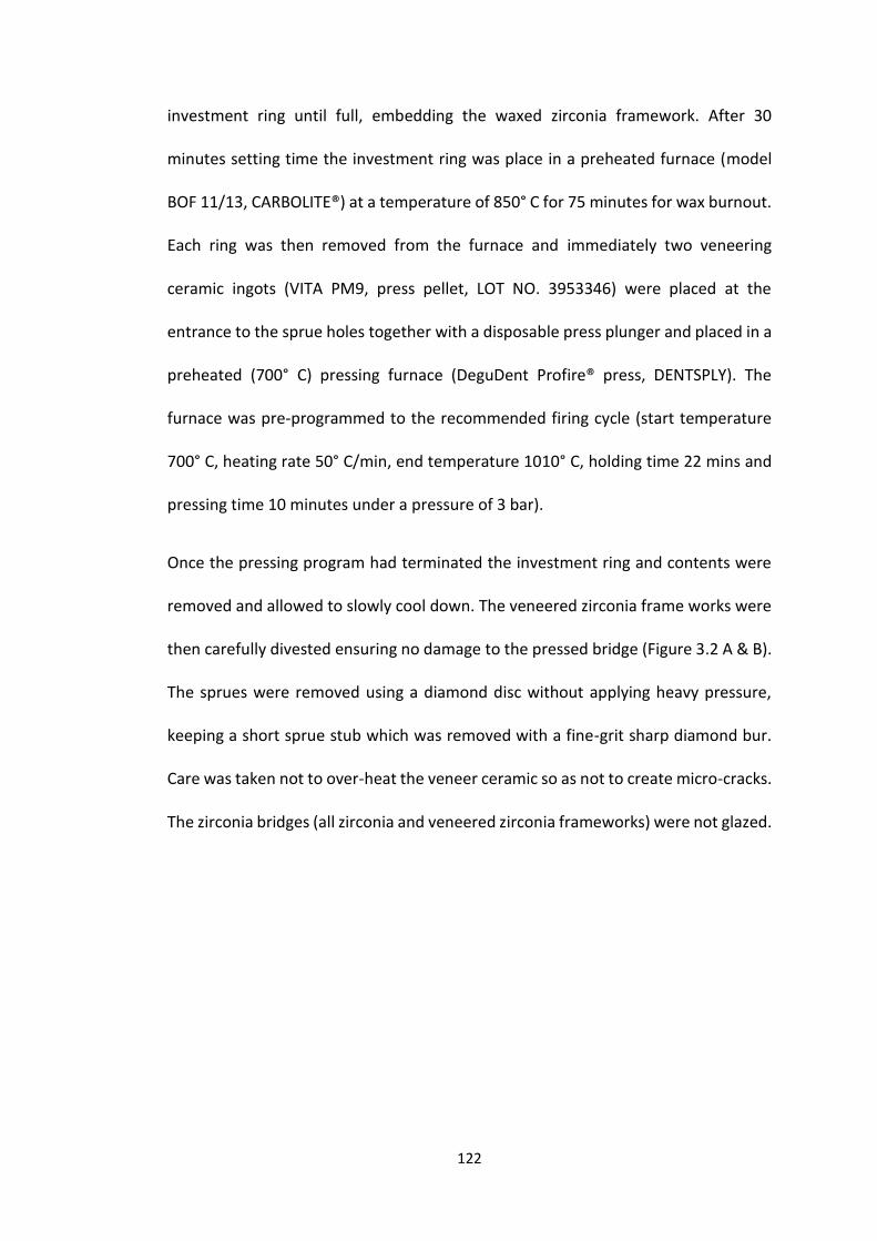
122
investment ring until full, embedding the waxed zirconia framework. After 30
minutes setting time the investment ring was place in a preheated furnace (model
BOF 11/13, CARBOLITE®) at a temperature of 850° C for 75 minutes for wax burnout.
Each ring was then removed from the furnace and immediately two veneering
ceramic ingots (VITA PM9, press pellet, LOT NO. 3953346) were placed at the
entrance to the sprue holes together with a disposable press plunger and placed in a
preheated (700° C) pressing furnace (DeguDent Profire® press, DENTSPLY). The
furnace was pre-programmed to the recommended firing cycle (start temperature
700° C, heating rate 50° C/min, end temperature 1010° C, holding time 22 mins and
pressing time 10 minutes under a pressure of 3 bar).
Once the pressing program had terminated the investment ring and contents were
removed and allowed to slowly cool down. The veneered zirconia frame works were
then carefully divested ensuring no damage to the pressed bridge (Figure 3.2 A & B).
The sprues were removed using a diamond disc without applying heavy pressure,
keeping a short sprue stub which was removed with a fine-grit sharp diamond bur.
Care was taken not to over-heat the veneer ceramic so as not to create micro-cracks.
The zirconia bridges (all zirconia and veneered zirconia frameworks) were not glazed.
123
Figure 3.2 (A) Zirconia framework with waxed-up bridge contour with sprues, (B)
pressed ceramic on zirconia framework (before finishing)
Bridge cementation
The study sample therefore consisted of three groups (15 all zirconia bridges, 15 un-
veneered zirconia frameworks and 15 veneered zirconia frameworks). Each zirconia
restoration was randomly appointed to one SLA model. RelyX™ Unicem 2 Clicker™
(3M ESPE, Seefeld, Germany, LOT No. 517676) self-adhesive Universal Resin Cement
was used as the luting cement. All-zirconia bridges were cemented on their SLA
models following manual mixing of the base and catalyst luting cement into an even
mix and application to the entire fit surface of each retainer as recommended by the
manufacturer. A custom made constant force device was used to seat each bridge
using a 30 N force for at least 5 - 6 minutes (Figure 3.3). Using a rectangular,
horizontal metal rod, the custom made cementation device ensured a constant
vertical force was applied across both abutment-retainers and the pontic at the same
time. The device was tested on numerous occasions using a weighing scale (Avery
Berkel, Model TB061) to make sure that the force application was correct and
A B
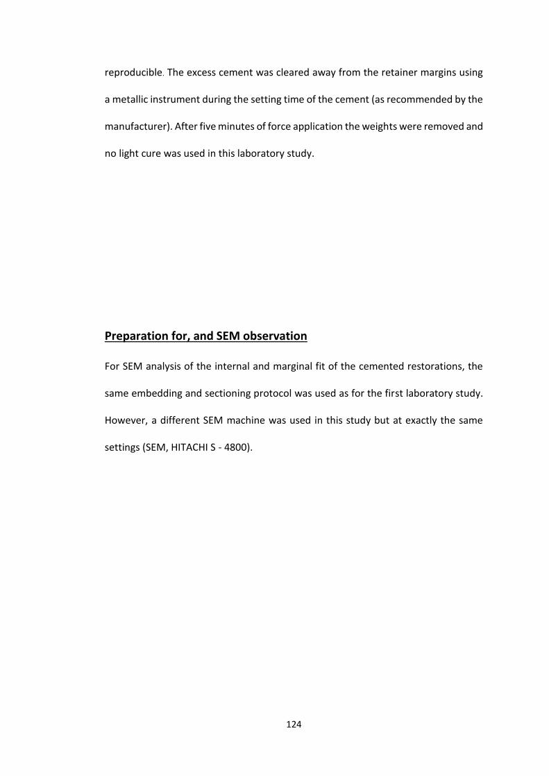
124
reproducible. The excess cement was cleared away from the retainer margins using
a metallic instrument during the setting time of the cement (as recommended by the
manufacturer). After five minutes of force application the weights were removed and
no light cure was used in this laboratory study.
Preparation for, and SEM observation
For SEM analysis of the internal and marginal fit of the cemented restorations, the
same embedding and sectioning protocol was used as for the first laboratory study.
However, a different SEM machine was used in this study but at exactly the same
settings (SEM, HITACHI S - 4800).
125
Figure 3.3 Force application device for cementation of the zirconia based bridges
30 N weight
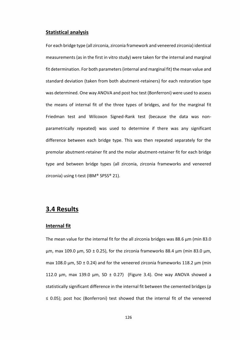
126
Statistical analysis
For each bridge type (all zirconia, zirconia framework and veneered zirconia) identical
measurements (as in the first in vitro study) were taken for the internal and marginal
fit determination. For both parameters (internal and marginal fit) the mean value and
standard deviation (taken from both abutment-retainers) for each restoration type
was determined. One way ANOVA and post hoc test (Bonferroni) were used to assess
the means of internal fit of the three types of bridges, and for the marginal fit
Friedman test and Wilcoxon Signed-Rank test (because the data was non-
parametrically repeated) was used to determine if there was any significant
difference between each bridge type. This was then repeated separately for the
premolar abutment-retainer fit and the molar abutment-retainer fit for each bridge
type and between bridge types (all zirconia, zirconia frameworks and veneered
zirconia) using t-test (IBM® SPSS® 21).
3.4 Results
Internal fit
The mean value for the internal fit for the all zirconia bridges was 88.6 µm (min 83.0
µm, max 109.0 µm, SD ± 0.25), for the zirconia frameworks 88.4 µm (min 83.0 µm,
max 108.0 µm, SD ± 0.24) and for the veneered zirconia frameworks 118.2 µm (min
112.0 µm, max 139.0 µm, SD ± 0.27) (Figure 3.4). One way ANOVA showed a
statistically significant difference in the internal fit between the cemented bridges (p
≤ 0.05); post hoc (Bonferroni) test showed that the internal fit of the veneered
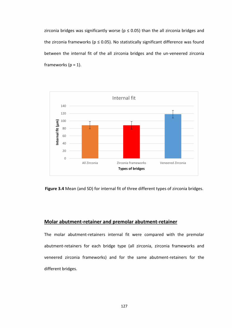
127
zirconia bridges was significantly worse (p ≤ 0.05) than the all zirconia bridges and
the zirconia frameworks (p ≤ 0.05). No statistically significant difference was found
between the internal fit of the all zirconia bridges and the un-veneered zirconia
frameworks (p = 1).
Figure 3.4 Mean (and SD) for internal fit of three different types of zirconia bridges.
Molar abutment-retainer and premolar abutment-retainer
The molar abutment-retainers internal fit were compared with the premolar
abutment-retainers for each bridge type (all zirconia, zirconia frameworks and
veneered zirconia frameworks) and for the same abutment-retainers for the
different bridges.
0
20
40
60
80
100
120
140
All Zirconia Zirconia frameworks Veneered Zirconia
Inte
rnal
fit
(µ
m)
Types of bridges
Internal fit

128
In the case of all zirconia bridges the mean value internal fit of the molar abutment-
retainers was 88.6 µm (min 82.0 µm, max 109.0 µm and SD ± 6.91) and for the
premolar the mean was 88.6 µm (min 80.0 µm, max 109.0 µm and SD ± 6.91). In
zirconia frameworks the mean value of internal fit of the molar abutment-retainer
was 88.4 µm (min 83.0 µm, max 109.0 µm and SD ± 7.05) and the premolar the mean
value was 88.3 µm (min 82.0 µm, max 109.0 µm and SD ± 7.05). The veneered zirconia
frameworks molar retainers mean reading was 118.3 µm (min 110.0 µm, max 139.0
µm and SD ± 7.97) whilst the premolar results were mean 118.3 µm (min 109.0 µm,
max 140.0 µm and SD ± 7.97). The t-test showed that for each type of bridge (all
zirconia, zirconia framework and veneered zirconia) there was no statistically
significant difference (p = 1) between the internal fit of the retainers on the premolar
and molar teeth.
Comparison of the internal fit for the molar abutment-retainers from all three bridge
types showed that there was a statistically significant difference between the three
types (p ≤ 0.01). Similarly comparison of the internal fit for the pre-molar abutment-
retainers for the three bridge types also showed a statistically significant difference
(p ≤ 0.05). The difference was due to the veneered zirconia retainers (molar and pre-
molar) which had worse internal fit compared to the all zirconia and zirconia
frameworks; there was no statistically significant difference between the
corresponding abutment-retainers for the latter two (p = 0.09).
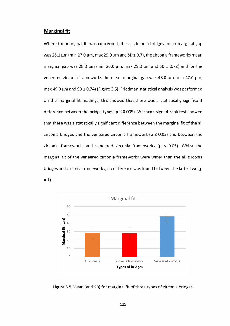
129
Marginal fit
Where the marginal fit was concerned, the all-zirconia bridges mean marginal gap
was 28.1 µm (min 27.0 µm, max 29.0 µm and SD ± 0.7), the zirconia frameworks mean
marginal gap was 28.0 µm (min 26.0 µm, max 29.0 µm and SD ± 0.72) and for the
veneered zirconia frameworks the mean marginal gap was 48.0 µm (min 47.0 µm,
max 49.0 µm and SD ± 0.74) (Figure 3.5). Friedman statistical analysis was performed
on the marginal fit readings, this showed that there was a statistically significant
difference between the bridge types (p ≤ 0.005). Wilcoxon signed-rank test showed
that there was a statistically significant difference between the marginal fit of the all
zirconia bridges and the veneered zirconia framework (p ≤ 0.05) and between the
zirconia frameworks and veneered zirconia frameworks (p ≤ 0.05). Whilst the
marginal fit of the veneered zirconia frameworks were wider than the all zirconia
bridges and zirconia frameworks, no difference was found between the latter two (p
= 1).
Figure 3.5 Mean (and SD) for marginal fit of three types of zirconia bridges.
0
10
20
30
40
50
60
All Zirconia Zirconia framework Veneered Zirconia
Mar
gin
al f
it (
µm
)
Types of bridges
Marginal fit
130
No statistically significant differences were found when the marginal fit of the molar
and premolar abutment-retainers were compared for the same bridge type (p = 1).
When the molar and premolar abutment-retainer marginal fits were separately
compared for each bridge type a statically significant difference was found between
the all zirconia bridges and the veneered zirconia frameworks and between the
zirconia frameworks and the veneered zirconia frameworks (p ≤ 0.05), with the
veneered zirconia framework having a wider marginal fit. All zirconia bridges and
zirconia frameworks showed no statistically significant difference between the
marginal fit of the two types of bridges (p = 1).
3.5 Discussion
Internal and marginal fit are both important factors to consider when constructing
and fitting any indirect dental restoration; they can be affected by aspects of the
tooth preparation, clinical techniques (e.g. impression technique) and various stages
in the manufacturing process (Martins et al., 2012).
In this study all such variables have been controlled to ensure that the only variable
was in the manufacture process. The same digital files of the prepared teeth from
laboratory study 1, which were obtained using the Lava™ Chairside Oral Scanner
(Lava™ C.O.S, 3M ESPE, Seefeld, Germany), were used in this laboratory study to

131
produce the un-sectioned SLA models (45 models) and design the zirconia
restorations (15 all zirconia bridges and 30 zirconia frameworks).
The variables investigated were the firing cycles and zirconia thickness. During the
first firing cycle of the semi-sintered bridges the restorations shrink by approximately
20.0 – 30.0 % in volume (Suttor et al., 2001, Beuer et al., 2008c), therefore it is
possible that placing the framework back in a hot furnace on two further occasions
to burn the wax off in preparation for the veneering process and for the injection
veneer process itself, could affect the dimensions of the restoration and hence fit
(Kunii et al., 2007, Romeo et al., 2009, Cho et al., 2012, Pak et al., 2010). In this regard,
in addition the difference in volume of a zirconia framework and an all zirconia bridge
could impact upon the amount of sintering shrinkage and fit of the restoration.
The results obtained from this study showed that firing cycles led to a significant
difference in the internal and marginal gaps between the veneered zirconia
frameworks and the all zirconia bridges and frameworks (P < 0.05). On the other
hand, the difference in the thickness between the all zirconia bridges and zirconia
framework did not show any significant difference (P = 1), the mean results of the
internal and marginal fit were 88.6 µm and 28.1 µm for the all zirconia bridges and
88.4 µm and 28.0 µm for the zirconia frameworks. The results of the all-zirconia
bridges and zirconia frameworks from this laboratory study are comparable with the

132
results of the first laboratory study (mean internal fit = 90.4 µm and mean marginal
fit 28.4 µm).
As in the previous study, RelyX Unicem (dual cured self-etching resin luting cement,
3M ESPS) was used to cement the zirconia based restorations in this study. A 30 N
constant vertical force was used to cement the zirconia bridges and frameworks
using a custom made force device, which is consistent with the mean force applied
by practitioners in the first laboratory study in this thesis and was within the range
of forces applied by practitioners in previous studies (Black and Amoore, 1993,
Mustafa et al., 2010). In this study the force was applied for five minutes which is
sufficient to allow for the chemical cure of the luting cement (RelyX Unicem, 3M
ESPE) as the margins of the bridges were not light cured. Clinically, dentists are
unlikely to maintain such a force over such a prolonged period of time, as
demonstrated in study 1. Alternatively, they are likely to seat the bridge, remove
excess cement whilst maintaining force and then light cure the margins. However,
the cementation process used in this study ensured an identical cementation force
and technique was applied to all the bridges which was monitored throughout the
study.
133
The same procedure that was used in the first laboratory study to measure the
internal and marginal gaps, namely SEM analysis, was used in this study and again
the greatest readings were recorded occlusally followed by the axial walls, with the
smallest reading in relation to the marginal gaps. As with the first laboratory study
the occlusal and axial reading were dealt with as one reading and separate from the
marginal gap.
In this study the results showed an increase in the internal and marginal fit following
the additional two firing cycles (de-waxing and veneering) for the veneered
framework: the mean internal gap was 118.2 µm and the mean marginal gap was
48.0 µm for the veneered framework compared to 88.4 µm and 28.0 µm for the un-
veneered zirconia frameworks. In reality, this could be exacerbated by an additional
firing cycle for glazing however the result of one previous study has shown that
glazing had no effect on the marginal fit (Vigolo and Fonzi, 2008). The pre-sintered
zirconia frameworks are stained using dyeing liquid, and this requires different firing
cycles than the cycle used in this experiment. When a zirconia is stained using the
dyeing liquid, the Lava™ Classic firing program is chosen which sinters the zirconia
framework at 1500° C for eight hours and 30 minutes. The longer firing cycle could
also have an effect on the internal and marginal fits.
134
Although there was a difference in fit between the veneered and un-veneered
zirconia frameworks and all zirconia restorations, all are considered to be within or
lower than the acceptable clinical range between 80.0 µm to 150.0 µm (McLean and
von Fraunhofer, 1971, Martinez-Rus et al., 2011). Metal ceramic restorations have
historically been considered the gold standard restoration (Sundh et al., 2005), and
studies comparing CAD CAM bridges with metal ceramic have shown comparable fit
in the order of 75.0 µm to 81.3 µm (Reich et al., 2005a, Reich et al., 2008, Song et al.,
2013).
Although a number of studies have now investigated the effect of ceramic veneering
on the internal and marginal gaps, the results appear to conflict (Table 3.1). Some of
the studies found that the additional firing cycles needed led to an increase in the
internal and marginal gap, other studies found no effect and finally two studies found
that firing cycle led to a decrease in the gap.
In this laboratory study, fully anatomical three unit bridges were constructed over an
ideal preparation of plastic teeth whereas most other studies have been carried out
on single crowns (Lee et al., 2008, Romeo et al., 2009, Pak et al., 2010, Euan et al.,
2012). Some studies prepared extracted natural teeth (Romeo et al., 2009, Pak et al.,
2010, Euan et al., 2012) and some used non-anatomical cylindrical metal studs as
abutments (Kunii et al., 2007, Komine et al., 2007, Bhowmik and Parkhedkar, 2011,
135
Miura et al., 2014) which could have had an impact on the results obtained. These
studies are summarised in Table 3.1.
It is clear that only three studies have investigated long span bridges. One of these
showed an increase in the cement gap in three, four and five unit restorations after
two firing cycles (Kunii et al., 2007), one showed no effect of two firing cycles on the
internal and marginal fit of four unit restorations (Vigolo and Fonzi, 2008) and one
found a decrease in the fit of four unit restorations after four firing cycles (Kohorst et
al., 2010). It is interesting to note that the two studies (one looking at four unit
restorations and one single unit restorations (Kohorst et al., 2010, Miura et al., 2014))
that found a decrease in fit after additional firing cycles, used the highest number of
firing cycles (four) compared to the majority that looked at two firing cycles (Table
3.1). The explanation for the decrease in fit may therefore be due to additional
shrinkage during the extra firing cycles.
Although it could be argued that the increase in the marginal gap that occurred in
this study following the firing for the ceramic veneering could affect the longevity of
the restoration, it is unlikely as the gaps were comparable or lower than those
previously reported, and in clinical trials the survival rate of all ceramic restorations
has been shown to be comparable with conventional metal ceramic bridges (Martins
et al., 2012, Rinke et al., 2015) in this respect.
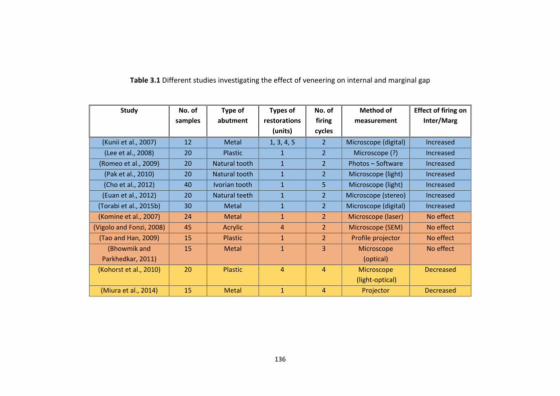
136
Table 3.1 Different studies investigating the effect of veneering on internal and marginal gap
Study No. of
samples
Type of
abutment
Types of
restorations
(units)
No. of
firing
cycles
Method of
measurement
Effect of firing on
Inter/Marg
(Kunii et al., 2007) 12 Metal 1, 3, 4, 5 2 Microscope (digital) Increased
(Lee et al., 2008) 20 Plastic 1 2 Microscope (?) Increased
(Romeo et al., 2009) 20 Natural tooth 1 2 Photos – Software Increased
(Pak et al., 2010) 20 Natural tooth 1 2 Microscope (light) Increased
(Cho et al., 2012) 40 Ivorian tooth 1 5 Microscope (light) Increased
(Euan et al., 2012) 20 Natural teeth 1 2 Microscope (stereo) Increased
(Torabi et al., 2015b) 30 Metal 1 2 Microscope (digital) Increased
(Komine et al., 2007) 24 Metal 1 2 Microscope (laser) No effect
(Vigolo and Fonzi, 2008) 45 Acrylic 4 2 Microscope (SEM) No effect
(Tao and Han, 2009) 15 Plastic 1 2 Profile projector No effect
(Bhowmik and
Parkhedkar, 2011)
15 Metal 1 3 Microscope
(optical)
No effect
(Kohorst et al., 2010) 20 Plastic 4 4 Microscope
(light-optical)
Decreased
(Miura et al., 2014) 15 Metal 1 4 Projector Decreased
137
The studies in Table 3.1 have all examined the effect of veneering ceramic using either the
press-over (pressable) technique or conventional free-hand layering technique. More
recently a new veneering technique called CAD-on has been introduced to fabricate the
veneering layer using Lithium-disilicate (Beuer et al., 2009f, Torabi et al., 2015b). When the
CAD-on veneering technique was compared with the layering and press-on veneering
technique, the results showed that all three veneering techniques led to an increase in the
marginal fit of the zirconia based restoration compared with the coping beneath; the zirconia
coping mean gap was 35.0 µm, which increased to 63.1 µm with the layering veneer
technique, 50.6 µm using the pressing technique and finally 51.5 µm with the CAD-on
veneering technique (Torabi et al., 2015b). Although all veneering techniques led to an
increase in fit all of them produced small marginal gaps and clinically acceptable results.
3.6 Conclusions
Within the limitation of this study, the following conclusions can be drawn:
1. The additional firing cycles used to veneer the zirconia frameworks have an effect on the
internal and marginal gaps, by leading to an increase in both.
2. The difference in the thickness of zirconia (all zirconia and zirconia frameworks) has no
effect on the internal and marginal fit of the restoration.

138
3. All zirconia bridges, zirconia frame works and veneered zirconia frameworks, produce
clinically acceptable internal and marginal gaps.
139
Chapter 4
Laboratory study 3
Three unit all zirconia bridges versus four
unit all zirconia bridges
140
Laboratory study 3
Three unit all zirconia bridges versus four unit all zirconia
bridges
4.1 Introduction
Since zirconia-based ceramics were introduced they have demonstrated superior mechanical
and aesthetic properties compared to other ceramics. Whilst initially used to construct inlays
and single unit restorations zirconia has increasingly been used for longer span bridges
(Abduo et al., 2010) due to its strength. As such long span zirconia bridges (e.g. three, four
and five unit bridges) are becoming the subject of a number of investigations. Some studies
have compared the fit of single unit crowns with that of bridges (Beuer et al., 2009e, Lee et
al., 2013a, Anunmana et al., 2014) (see discussion), a number have looked at the fit of bridges
with one specific span length (Komine et al., 2005, Reich et al., 2005a, Bindl and Mormann,
2007, Gonzalo et al., 2008, Reich et al., 2008, Vigolo and Fonzi, 2008, Att et al., 2009, Beuer
et al., 2009a, Beuer et al., 2009d, Dittmer et al., 2009, Gonzalo et al., 2009, Kohorst et al.,
2009), but only two have compared the effect of increasing the span of bridges on fit in the
same study (Tinschert et al., 2001b, Lee et al., 2013a). The results from these two studies
suggest a trend toward a deterioration in fit with increasing span length. However this did not
reach a statistically significant level in the first study (Tinschert et al., 2001b). The other study
by Lee et al., 2013 showed that there was statistically significant difference between single
unit crown, four unit bridge and six unit bridges (Lee et al., 2013a).
141
As pre-sintered zirconia is affected by approximately 20.0 – 30.0 % shrinkage on firing (Suttor
et al., 2001) it could be expected that this would have a bigger impact upon the fit of longer
span bridges. Furthermore, veneering the zirconia frameworks has been shown in Laboratory
Study 2 in this thesis to have an impact on the fit of three unit bridges, it is possible that this
impact could again be exacerbated with longer span bridges. For those studies that have
examined at four unit bridges, no consensus was reached on the impact of ceramic veneering,
with one showing an increase, one showing no impact in marginal gap and the other showing
a decrease in marginal gap. (Kunii et al., 2007, Vigolo and Fonzi, 2008, Kohorst et al., 2010).
As internal and marginal gaps have the potential to affect the survival and longevity of the
indirect dental restoration (Subasi et al., 2012, Lee et al., 2013a), and due to the paucity in
evidence assessing the impact of altering the length of the span of the bridge has on this,
there is a need for further investigation.
4.2 Aims and objectives
The aim of this laboratory study was to compare the effect that the length of the span of all
zirconia bridges (three unit and four unit) made using the Lava COS intra oral scanner, has on
the internal and marginal fit.
142
4.3 Material and Methods
Tooth preparation and Quality control
Two new plastic teeth were selected and prepared for a four unit bridge (abutment teeth 14
and 17 and pontics teeth 15 and 16). The same “quality control” as used in the first laboratory
study were followed to ensure that all the requirements of standardised tooth preparations
were achieved (taper of the teeth, finish-line and occlusal reduction). The mean total occlusal
convergence angle for tooth 14 was 11.6° (min 11.2° – max 11.8°) and for tooth 17 was 11.5°
(min 11.2°- max 11.7°), the mean chamfer depth around tooth 14 was 1.1 mm (min 1.0 mm –
max 1.4 mm) and tooth 17 was 1.2 mm (min 1.0 mm – max 1.5 mm).
Digital Impression and SLA models
Once the ideal tooth preparations were achieved for the four unit bridge and confirmed
through the quality control process, the prepared teeth on the original model were scanned
with the Lava™ Chairside Oral Scanner (Lava™ C.O.S, 3M ESPE, Seefeld, Germany) according
to the manufacturer’s instructions to produce 15 (four unit) identical non-sectioned
Stereolithography models (SLA models, In’Tech Industries, Inc. USA). The same procedure
that was used in the first laboratory study for the three unit bridges was used for the four unit
bridge abutments scanning.
143
Bridge design and fabrication
The data captured of the prepared teeth (14 and 17) were used to design the four unit all
zirconia bridges in the CAD system, the same settings that were used for the three unit bridges
were used for the four unit bridges, to ensure that the bridges were identical from a
production point of view and that the only difference was in the length of the span of the
bridge (die spacer 0.095 mm extra vertical (occlusal), 0.075 mm extra horizontal (buccal,
mesial, distal and lingual) and minimum coping thickness 0.5 mm). Semi-sintered zirconia
multi blocks were used to fabricate the all-zirconia bridges (3M ESPE, Seefeld, Germany, LOT
No. 470281 X 3 and 472678 X 5) using a five axis CAM milling machine and dry milling process
machine (Lava™ CNC 500 Milling System, 3M ESPE). The semi-sintered all-zirconia bridges
were placed in a custom furnace (Lava™ furnace 200, (3M ESPE, Seefeld, Germany) to fully
sinter the zirconia framework at 1500° C for 4 hours 48 minutes (LAVA 1500, Non-shaded).
The results for the internal and marginal fit of the three-unit all-zirconia bridges determined
in the second laboratory study were used in this study.
Bridge cementation
The 15 four-unit all-zirconia bridges were cemented permanently to their designated un-
sectioned SLA models. The same steps that were used in the second laboratory study for
cementing the three unit all-zirconia bridges were used in this laboratory study (See
laboratory study two). RelyX™ Unicem 2 Clicker™ (3M ESPE, Seefeld, Germany, LOT No.
517676) self-adhesive Universal Resin Cement was used as the luting cement. Zirconia bridges
were cemented on their SLA model using a constant vertical seating force of 30 N for five
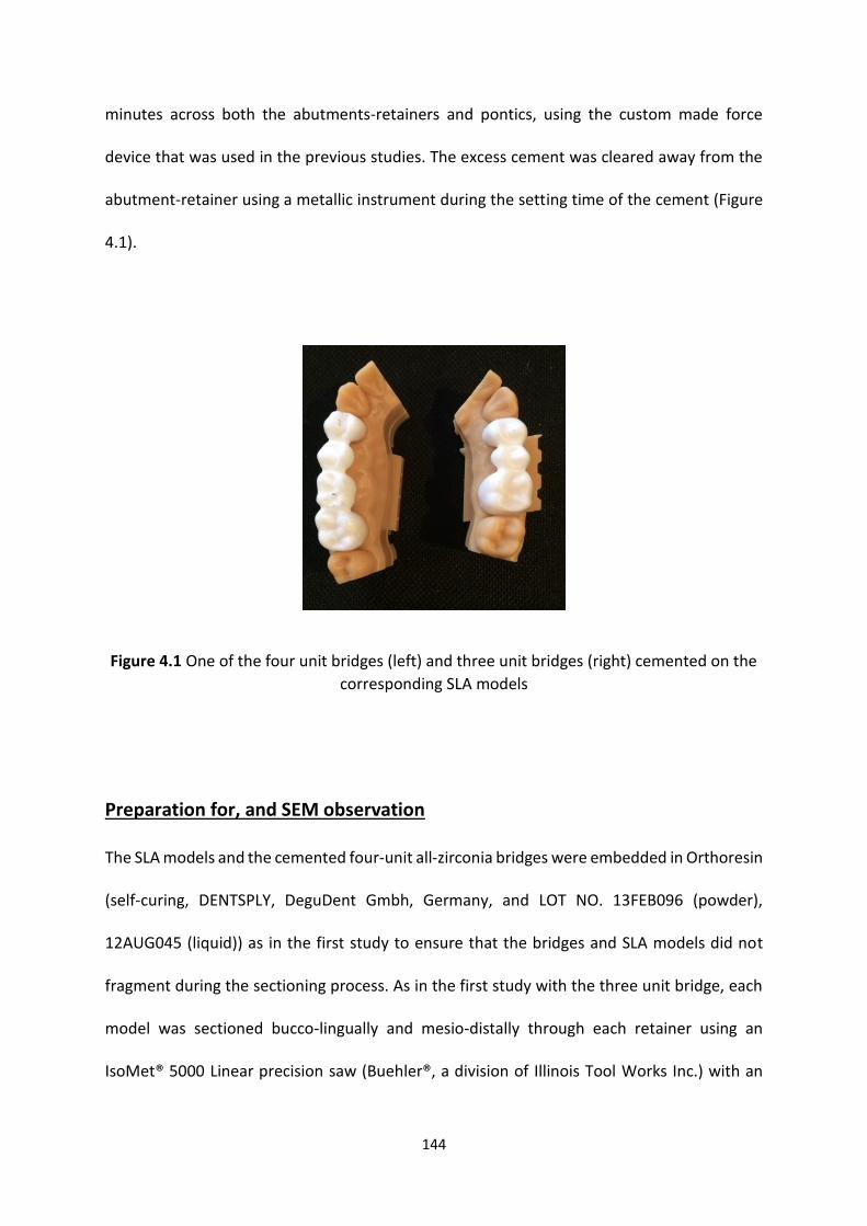
144
minutes across both the abutments-retainers and pontics, using the custom made force
device that was used in the previous studies. The excess cement was cleared away from the
abutment-retainer using a metallic instrument during the setting time of the cement (Figure
4.1).
Figure 4.1 One of the four unit bridges (left) and three unit bridges (right) cemented on the
corresponding SLA models
Preparation for, and SEM observation
The SLA models and the cemented four-unit all-zirconia bridges were embedded in Orthoresin
(self-curing, DENTSPLY, DeguDent Gmbh, Germany, and LOT NO. 13FEB096 (powder),
12AUG045 (liquid)) as in the first study to ensure that the bridges and SLA models did not
fragment during the sectioning process. As in the first study with the three unit bridge, each
model was sectioned bucco-lingually and mesio-distally through each retainer using an
IsoMet® 5000 Linear precision saw (Buehler®, a division of Illinois Tool Works Inc.) with an
145
IsoMet® diamond wafering blade (178.0 mm x 0.6 mm, Buehler®) under water coolant, for
subsequent examination under the Scanning Electron Microscope (SEM). Each retainer and
abutment tooth was therefore sectioned into 4 segments.
SEM observation
Sectioned samples from the four-unit all-zirconia bridges were mounted on aluminium studs
using double sided carbon tape as was done in the first study with the three-unit bridges, then
painted with silver conductive paint (conductive pen, MG chemicals). The samples were then
examined under the Scanning Electron Microscope (SEM, HITACHI S - 4800) at 150x
magnification operating at acceleration voltage of 15 kV (to measure the cement space
internally and marginally). The images were viewed on a 19” flat screen using Microscope
Control software. For each bridge, measurements of marginal gap were made at eight
predefined segments (four from the premolar and four from the molar). Each segment had
two walls, similar to the three unit bridges in the previous studies (see laboratory study two).
Statistical analysis
For the four-unit all-zirconia bridges, identical internal and marginal cement gaps
measurements were recorded and used to check if there was any statistical differences
between the two bridge types. One way ANOVA was used to assess the internal and marginal
fits of the four unit all zirconia bridges (IBM® SPSS® 21). The results obtained for the three-
unit bridges determined and used in the previous laboratory studies (laboratory study two)
were also used to compare with the four-unit bridge results obtained in this laboratory study.
146
This was repeated separately for the premolar abutment-retainer fit and the molar abutment-
retainer fit for each bridge type and between bridge types (three unit and four unit all zirconia
bridges) using one-way ANOVA (IBM® SPSS® 21).
4.4 Results
Internal fit
The mean internal fit of the three-unit all zirconia bridges was 88.4 µm (min 82.0 µm, max
108.0 µm and SD ± 6.9) and it was 88.5 µm (min 83.0 µm, max 109.0 µm and SD ± 7.0). For
the four-unit all zirconia bridges. There were no statistically significant differences between
the two types of bridges (p = 0.79) (Figure 4.2).
Molar abutment-retainer and premolar abutment-retainer
The molar and premolar abutment-retainers were compared from the three unit bridges with
each other using one-way ANOVA to determine if there were any statistically significant
differences between the abutment-retainers. The results showed that there were no
statistically significant differences between the two abutment – retainer tooth types (p =
0.34). For the molar and premolar abutment-retainers of the four unit bridges, the results
showed that there were no statistically significant differences between the two abutment –
retainers tooth types (p = 0.57)
When considering the molars abutment-retainer results, there were no statistically significant
differences for the two different span bridges (p = 0.42). For the premolar abutment-retainer
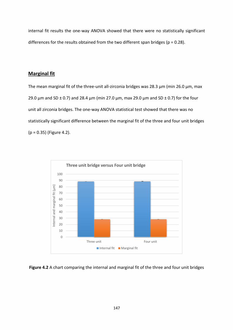
147
internal fit results the one-way ANOVA showed that there were no statistically significant
differences for the results obtained from the two different span bridges (p = 0.28).
Marginal fit
The mean marginal fit of the three-unit all-zirconia bridges was 28.3 µm (min 26.0 µm, max
29.0 µm and SD ± 0.7) and 28.4 µm (min 27.0 µm, max 29.0 µm and SD ± 0.7) for the four
unit all zirconia bridges. The one-way ANOVA statistical test showed that there was no
statistically significant difference between the marginal fit of the three and four unit bridges
(p = 0.35) (Figure 4.2).
Figure 4.2 A chart comparing the internal and marginal fit of the three and four unit bridges
0
10
20
30
40
50
60
70
80
90
100
Three unit Four unit
Inte
rnal
an
d m
argi
nal
fit
(µ
m)
Three unit bridge versus Four unit bridge
Internal fit Marginal fit
148
Molar abutment-retainer and premolar abutment-retainer
A one-way ANOVA of the marginal fit results demonstrated that the three-unit bridge results
showed that there was no statistically significant difference between the molar and premolar
abutment-retainers (p = 0.43); the same findings were found for the four-unit bridge
abutment - retainers (molar and premolar) (p = 0.19).
The molar abutment-retainer from both types of bridges marginal fit results showed that
there were no statistically significant difference in relation to marginal fit (p = 1); identical
results were obtained for the premolar abutment-retainers (p = 1).
4.5 Discussion
Both internal and marginal fits can be affected by many factors such as the CAD CAM system
used, sintering status of the zirconia when milled and the span length of the constructed
indirect dental restoration, to name but a few (Abduo et al., 2010).
The aim of this study was to compare the internal and marginal fits of different span length
zirconia bridges. The bridges constructed in this laboratory study were all-zirconia three-unit
and four-unit bridges; no veneered frameworks were used in order to eliminate any effect of
the ceramic veneering process on the internal and marginal fit of the bridges. Both three -
and four - unit bridges were constructed following exactly the same process as used in the
first and second laboratory studies and randomly allocated to the SLA models so that the only
difference between the bridges was in the number of units. The span lengths were chosen
because these are the most commonly used span lengths for bridges constructed in Dundee
dental hospital (data collected over the past five years (2011 - 2015)). Longer span bridges are
149
less common due to the greater indication for removable prostheses and the introduction of
dental implants (Hemmings and Harrington, 2004).
The results of this laboratory study of both the three-unit all-zirconia bridges (mean internal
gap 88.4 µm and mean marginal fit 28.3 µm) and the four-unit all-zirconia bridges (mean
internal gap 88.5 µm and mean marginal fit 28.4 µm) were comparable to other studies (see
Table 4.1), where the internal fit results of the studies ranged from 54.2 µm to 144.0 µm and
the marginal fit ranged from 9.0 µm to 203.1 µm (Tinschert et al., 2001b, Komine et al., 2005,
Reich et al., 2005a, Bindl and Mormann, 2007, Gonzalo et al., 2008, Reich et al., 2008, Vigolo
and Fonzi, 2008, Att et al., 2009, Beuer et al., 2009a, Beuer et al., 2009d, Beuer et al., 2009e,
Dittmer et al., 2009, Gonzalo et al., 2009, Kohorst et al., 2009, Kohorst et al., 2010, Lee et al.,
2013a, Anunmana et al., 2014).
Most of the studies included in Table 4.1 investigated the fit of bridges with one specific span
namely either three (n = 7 studies, 184 bridges) or four unit (n = 6 studies, 194 bridges)
bridges. Thus direct comparison between studies of different span bridges without any other
confounding variables such CAD CAM system used, veneering ceramic (or not), configuration
(straight or curved arch) and zirconia state (milled in pre-sintered or sintered state), is
difficult. Only two studies in Table 4.1 directly compared bridges of different span length
within the same study (Tinschert et al., 2001b, Lee et al., 2013a), one also comparing results
with single unit crowns (Lee et al., 2013a) and two further studies compared single unit
crowns with longer span bridges (Beuer et al., 2009e, Anunmana et al., 2014).
When the results of the previous studies in Table 4.1 are compared, it is clear that there are
large differences between their internal and marginal fit measurements. Where the minimum
marginal fits are concerned, this can range from 9.0 µm to 102.0 µm, an approximately 11

150
fold difference between studies assessing at three-unit and four-unit bridges (Beuer et al.,
2009d, Gonzalo et al., 2009, Kohorst et al., 2010). Similarly, studies have recorded large
differences in maximum marginal fit, ranging from 15.0 µm to 203.1 µm for a three-unit and
six-unit bridge respectively; a 13 fold variation (Beuer et al., 2009d, Lee et al., 2013a).
Application of a meta-analysis to the various studies in Table 4.1 would be impossible due to
the heterogeneity between the studies. However, Figure 4.3 shows the minimum and
maximum marginal gap recorded in all the studies cited and shows a trend toward increased
marginal gap with increasing span length.
Three studies compared single unit restorations with longer span zirconia bridges and all
three showed significant increases in marginal gap with the bridges (Beuer et al., 2009e, Lee
et al., 2013a, Anunmana et al., 2014). Anunmana et al. (2014), compared single crowns made
separately on premolar (tooth 25) and molar (tooth 27) teeth that were subsequently linked
with three unit zirconia bridges. When the same abutment teeth were linked in a bridge, they
found there was a significant increase in the internal and marginal fit/gap of the three unit
bridges at both premolar and molar abutments (Anunmana et al., 2014). It would appear from
these studies that bridges have an inferior fit compared to single unit zirconia crowns, but the
differences, whilst statistically significant, are very small and unlikely to have a clinical impact
(Table 4.1).
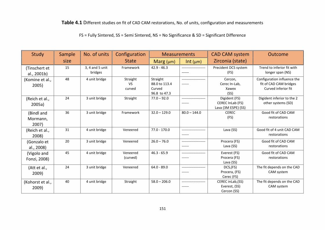
151
Table 4.1 Different studies on fit of CAD CAM restorations, No. of units, configuration and measurements
FS = Fully Sintered, SS = Semi Sintered, NS = No Significance & SD = Significant Difference
Study Sample size
No. of units Configuration State
Measurements CAD CAM system Zirconia (state)
Outcome
Marg (µm) Int (µm) (Tinschert et al., 2001b)
15 3, 4 and 5 unit bridges
Framework 42.9 - 46.3 --------------------------
Precident DCS system (FS)
Trend to inferior fit with longer span (NS)
(Komine et al., 2005)
48 4 unit bridge Straight VS
curved
Straight 88.0 to 113.4 Curved 96.8 to 47.3
--------------------------
Cercon, Cerec In-Lab,
Xawex (SS)
Configuration influence the fit of CAD CAM bridges
Curved inferior fit
(Reich et al., 2005a)
24 3 unit bridge Straight 77.0 – 92.0 --------------------------
Digident (FS) CEREC InLab (FS)
Lava (3M ESPE) (SS)
Digident inferior to the 2 other systems (SD)
(Bindl and Mormann,
2007)
36 3 unit bridge Framework 32.0 – 129.0 80.0 – 144.0 CEREC (FS)
Good fit of CAD CAM restorations
(Reich et al., 2008)
31 4 unit bridge Veneered 77.0 - 170.0 --------------------------
Lava (SS) Good fit of 4 unit CAD CAM restorations
(Gonzalo et al., 2008)
20 3 unit bridge Veneered 26.0 – 76.0 --------------------------
Procera (FS) Lava (SS)
Good fit of CAD CAM restorations
(Vigolo and Fonzi, 2008)
45 4 unit bridge Veneered (curved)
46.3 - 65.9 --------------------------
Everest (FS) Procera (FS)
Lava (SS)
Good fit of CAD CAM restorations
(Att et al., 2009)
24 3 unit bridge Veneered 64.0 - 89.0 --------------------------
DCS,(FS) Procera, (FS)
Cerec (FS)
The fit depends on the CAD CAM system
(Kohorst et al., 2009)
40 4 unit bridge Straight 58.0 – 206.0 --------------------------
CEREC inLab,(SS) Everest, (SS) Cercon (SS)
The fit depends on the CAD CAM system
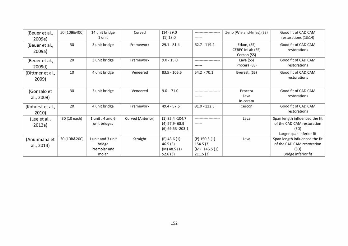
152
(Beuer et al., 2009e)
50 (10B&40C) 14 unit bridge 1 unit
Curved (14) 29.0 (1) 13.0
--------------------------
Zeno (Wieland-Imes),(SS) Good fit of CAD CAM restorations (1&14)
(Beuer et al., 2009a)
30 3 unit bridge Framework 29.1 - 81.4 62.7 - 119.2 Etkon, (SS) CEREC InLab (SS)
Cercon (SS)
Good fit of CAD CAM restorations
(Beuer et al., 2009d)
20 3 unit bridge Framework 9.0 - 15.0 --------------------------
Lava (SS) Procera (SS)
Good fit of CAD CAM restorations
(Dittmer et al., 2009)
10 4 unit bridge Veneered 83.5 - 105.5 54.2 - 70.1 Everest, (SS) Good fit of CAD CAM restorations
(Gonzalo et al., 2009)
30 3 unit bridge Veneered 9.0 – 71.0 --------------------------
Procera Lava
In-ceram
Good fit of CAD CAM restorations
(Kohorst et al., 2010)
20 4 unit bridge Framework 49.4 - 57.6 81.0 - 112.3 Cercon
Good fit of CAD CAM restorations
(Lee et al., 2013a)
30 (10 each) 1 unit , 4 and 6 unit bridges
Curved (Anterior) (1) 85.4 -104.7 (4) 57.9- 68.9 (6) 69.53 -203.1
--------------------------
Lava Span length influenced the fit of the CAD CAM restoration
(SD) Larger span inferior fit
(Anunmana et al., 2014)
30 (10B&20C) 1 unit and 3 unit bridge
Premolar and molar
Straight (P) 43.6 (1) 46.5 (3) (M) 48.5 (1) 52.6 (3)
(P) 150.5 (1) 154.5 (3) (M) 146.5 (1) 211.5 (3)
Lava Span length influenced the fit of the CAD CAM restoration
(SD) Bridge inferior fit
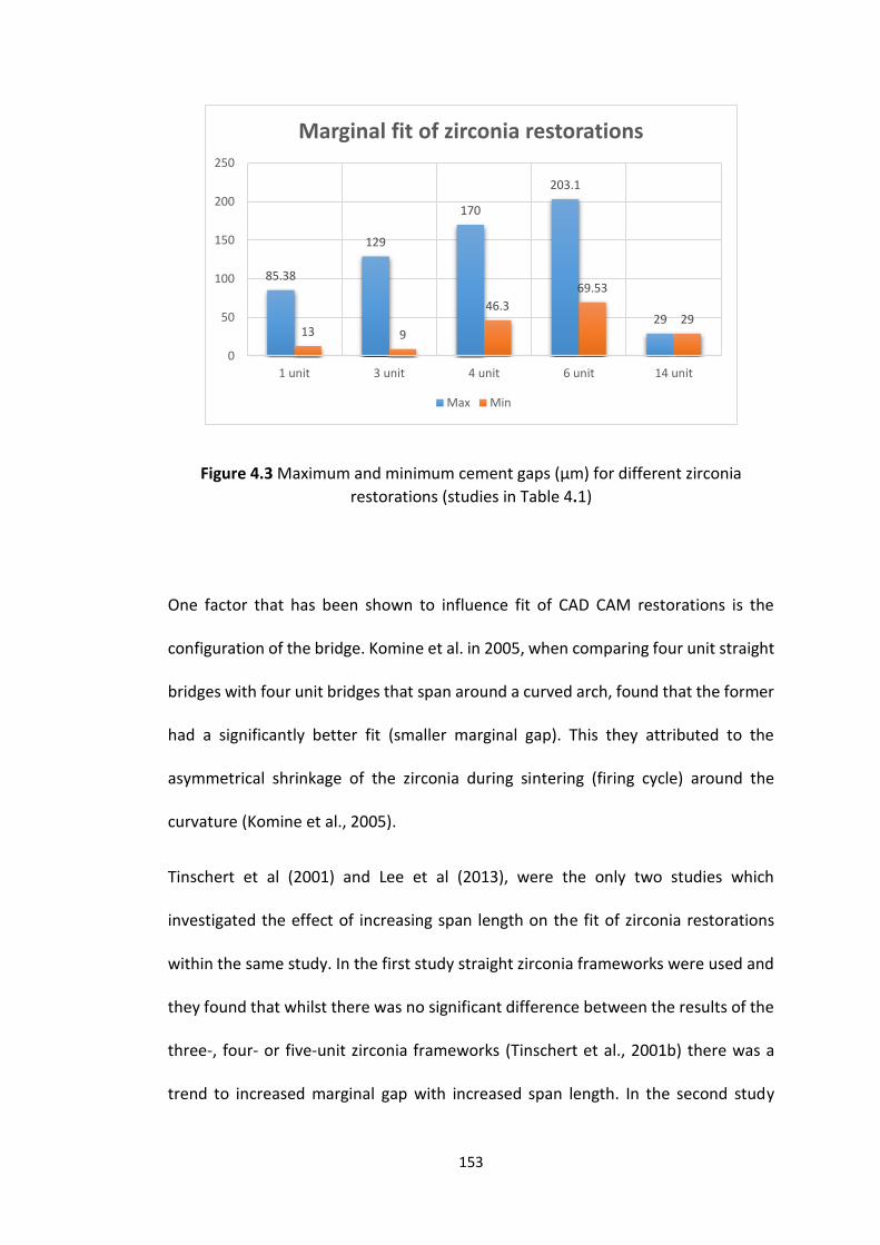
153
Figure 4.3 Maximum and minimum cement gaps (µm) for different zirconia
restorations (studies in Table 4.1)
One factor that has been shown to influence fit of CAD CAM restorations is the
configuration of the bridge. Komine et al. in 2005, when comparing four unit straight
bridges with four unit bridges that span around a curved arch, found that the former
had a significantly better fit (smaller marginal gap). This they attributed to the
asymmetrical shrinkage of the zirconia during sintering (firing cycle) around the
curvature (Komine et al., 2005).
Tinschert et al (2001) and Lee et al (2013), were the only two studies which
investigated the effect of increasing span length on the fit of zirconia restorations
within the same study. In the first study straight zirconia frameworks were used and
they found that whilst there was no significant difference between the results of the
three-, four- or five-unit zirconia frameworks (Tinschert et al., 2001b) there was a
trend to increased marginal gap with increased span length. In the second study
85.38
129
170
203.1
2913 9
46.3
69.53
29
0
50
100
150
200
250
1 unit 3 unit 4 unit 6 unit 14 unit
Marginal fit of zirconia restorations
Max Min
154
anterior curved bridges with four units (upper lateral incisor to upper lateral incisor
replacing central incisors) and six units (upper canine to canine replacing four
incisors) were compared and a significant difference between the four- unit and six-
unit bridges were found, with the longer span bridges having a greater increase in
the marginal gap (Lee et al., 2013a). The results of the latter study may not only be
due to the increase in span but also the use of a greater curvature, thus supporting
the findings of Komine et al., (2005) that curved restorations undergo greater
distortion on firing (Komine et al., 2005).
The results that were obtained from this laboratory study comparing identically
manufactured bridges, but only differing in span length, has shown that three-unit
bridges and four-unit bridges did not have any statistically significant difference in
relation to internal or marginal fit. Similarly, when the fit in relation to the smaller
premolars and larger molar retainers were assessed separately, again there was no
difference in fit due to retainer/abutment size. Thus it would appear that Lava™, 3M
ESPE CAD CAM system is able to accurately compensate for zirconia sintering
shrinkage in relation to bridges with significant dimensional differences, results
broadly in agreement with the zirconia framework study by Tinschert et al (2001).
Whilst the zirconia milling state (fully-sintered or semi-sintered) can have an effect
on the internal and marginal fit (Abduo et al., 2010, Miyazaki et al., 2013), no study
has compared the two in the same study using the same CAD CAM system for bridges.
Three studies compared different CAD CAM systems with some systems using fully
sintered and some semi-sintered blocks for milling. Whilst the studies by Gonzalo et
al., (2008) and Vigolo and Fonzi (2008) demonstrated no difference between the

155
sintered states of the zirconia blocks (Gonzalo et al., 2008, Vigolo and Fonzi, 2008),
the study by Reich et al., (2005) showed the fully sintered blocks used by the Digident
CAD CAM system resulted in an inferior fit compared to the semi-sintered blocks
used by the Lava system (Reich et al., 2005a). This is the reverse of what would be
expected, as fully sintered blocks have already undergone the sintering shrinkage
prior to milling and in theory should have a more accurate fit, the difference here
may simply be due to the CAD CAM system itself being less accurate.
Finally, the internal and marginal fit results of this laboratory study were comparable
to the results of the first and second laboratory studies in this thesis and previous
studies of conventional restorations (Stappert et al., 2008, Baig et al., 2010).
4.6 Conclusion
Within the limitation of this study, the following conclusions can be drawn:
1. All-zirconia three- and four-unit bridges produced by Lava CAD CAM system, are
within the clinically acceptable range.
2. There was no significant difference between the three- and four-unit bridges, in
relation to the internal and marginal fit.
3. The span length of all-zirconia bridges is unlikely to have an impact on the internal
and marginal fit of the all-zirconia bridges.
156
Chapter 5
Laboratory study 4
The effect of veneering on the
strength of three unit zirconia
based bridges
157
Laboratory study 4
The effect of veneering on the strength of three unit zirconia
based bridges
5.1 Introduction
For the past five decades, metal ceramic has been the choice of material for extra-
coronal restorations such as crowns and conventional bridge retainers (Reitemeier
et al., 2013), this being because it combines the superior mechanical properties of
the metal coping with the aesthetics of the veneering ceramic. Such restorations
have enjoyed good long-term success / survival (Tan et al., 2004) and whilst good
aesthetic outcomes can be achieved with metal ceramic restorations the demand for
a “metal free approach” to dentistry and the drive for even better aesthetics,
strength and biocompatibility has led to increased research effort into all ceramic
restorations over the last two decades (Sundh et al., 2005, Cortellini et al., 2006).
Most recently, all ceramic restorations have involved the use of CAD CAM technology
to mill zirconia into a coping similar to the metal coping of a metal ceramic crown
have received attention. The zirconia coping so produced has enhanced strength
(Agustín-Panadero et al., 2014), which is reported to withstand forces up to 6000 N,
(Chen et al., 1999, Sundh and Sjogren, 2004, Zahran et al., 2008) but is chalky white
in colour, monochromatic and opaque and hence is thought not to produce highly
aesthetic restorations as a material on its own (Alghazzawi et al., 2012, Zhang et al.,
2012, Xie et al., 2015). As such the zirconia is milled into a coping to provide the
158
strength and a veneering aesthetic ceramic is applied to this to produce the
characterisation and translucency required to create a restoration with a natural
appearance. Whilst the principle in construction of the two types of restorations is
similar the all ceramic restorations have a better translucency overall, are less
opaque or “dull” in appearance and mimic better the aesthetic properties of a natural
tooth compared to the metal ceramic counterpart.
Whilst zirconia is an extremely strong material, other factors can affect the strength
of the completed restoration, such as application of the ceramic veneer layer. It is
the latter that is most frequently implicated in the failure rate of such all ceramic
restorations, and the strength is related to both the thickness of the coping /
framework and veneering ceramic layer (Lund and Barber, 1992, Wakabayashi and
Anusavice, 2000).
5.2 Aims and objectives
The aims of this study were therefore to investigate whether ceramic veneering of
zirconia frameworks had any effect on the strength of the restoration and to
determine whether there was any difference in strength between un-veneered
zirconia frameworks (substructure), veneered zirconia bridges and all-zirconia
bridges.
159
5.3 Materials and Methods
Tooth preparation and quality control
The ideal teeth preparations that were achieved in the first laboratory test were
scanned, and used for this laboratory experiment.
Digital Impression and bridge manufacture
The same digital files that were used in the first and second laboratory tests were
used in this laboratory test to produce 45 zirconia bridges (15 all zirconia bridges and
30 zirconia frameworks). The same settings were used for these bridges in the CAD
system (die spacer 0.095 mm extra vertical (occlusal), 0.075 mm extra horizontal
(buccal, mesial, distal and lingual) and minimum coping thickness 0.5 mm. This
process ensured the manufacture of 15 identical three-unit all-zirconia bridges and
30 identical zirconia frameworks using a five axis CAM milling machine (Lava™ CNC
500 Milling System, 3M ESPE) and dry milling process. Semi-sintered zirconia multi
blocks were used to fabricate the all-zirconia bridges (3M ESPE, Seefeld, Germany,
LOT No. 470281, LOT No. 472678 and LOT No. 472678). The semi-sintered all-zirconia
bridges were placed in a custom furnace (Lava™ furnace 200, 3M ESPE, Seefeld,
Germany) to fully sinter the zirconia framework at 1500° C for 4 hours 48 minutes
(LAVA 1500, Non-shaded).
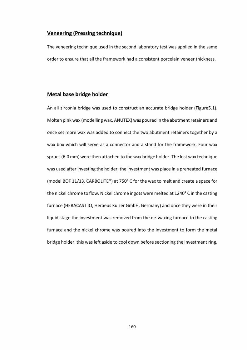
160
Veneering (Pressing technique)
The veneering technique used in the second laboratory test was applied in the same
order to ensure that all the framework had a consistent porcelain veneer thickness.
Metal base bridge holder
An all zirconia bridge was used to construct an accurate bridge holder (Figure5.1).
Molten pink wax (modelling wax, ANUTEX) was poured in the abutment retainers and
once set more wax was added to connect the two abutment retainers together by a
wax box which will serve as a connector and a stand for the framework. Four wax
sprues (6.0 mm) were then attached to the wax bridge holder. The lost wax technique
was used after investing the holder, the investment was place in a preheated furnace
(model BOF 11/13, CARBOLITE®) at 750° C for the wax to melt and create a space for
the nickel chrome to flow. Nickel chrome ingots were melted at 1240° C in the casting
furnace (HERACAST IQ, Heraeus Kulzer GmbH, Germany) and once they were in their
liquid stage the investment was removed from the de-waxing furnace to the casting
furnace and the nickel chrome was poured into the investment to form the metal
bridge holder, this was left aside to cool down before sectioning the investment ring.
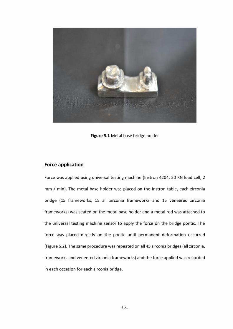
161
Figure 5.1 Metal base bridge holder
Force application
Force was applied using universal testing machine (Instron 4204, 50 KN load cell, 2
mm / min). The metal base holder was placed on the Instron table, each zirconia
bridge (15 frameworks, 15 all zirconia frameworks and 15 veneered zirconia
frameworks) was seated on the metal base holder and a metal rod was attached to
the universal testing machine sensor to apply the force on the bridge pontic. The
force was placed directly on the pontic until permanent deformation occurred
(Figure 5.2). The same procedure was repeated on all 45 zirconia bridges (all zirconia,
frameworks and veneered zirconia frameworks) and the force applied was recorded
in each occasion for each zirconia bridge.
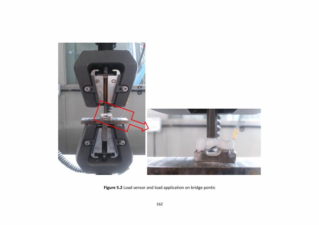
162
Figure 5.2 Load sensor and load application on bridge pontic
163
Statistical analysis
For each type of three zirconia bridges the force that led to fracture of the bridge was
recorded and used to statistically test if there was any differences between the groups. One
way ANOVA and post hoc testing (Bonferroni) were used to assess the forces applied by the
Instron machine and if there was any significant difference between the different groups of
bridges (IBM® SPSS® 21).
5.4 Results
Bridges showed different fracture behaviour when force was applied, the results showed that
there was statistically significant difference between the three groups (p ≤ 0.005).Post hoc
testing however showed that there was a very highly statistical significant difference between
all the three types of bridges (All zirconia, Veneered zirconia and zirconia Framework (p =
0.000)).
All zirconia bridges
All zirconia bridges showed the highest resistance force (N), the mean force was 1858.5 N
(min 1348.0 N, max 2968.0 N, SD ± 430.5). All zirconia bridges showed an immediate fracture
when the force was applied to them by the Instron machine (Figure 5.3), but it showed
different fracture locations (10 in premolar, 1 molar and premolar, and 4 in the connectors,
(Table 5.1)).

164
Figure 5.3 Graph shows the immediate fracture of all zirconia bridge
Table 5.1 Fracture behavior of the all zirconia bridges
All zirconia
10 bridges Premolar fracture (Retainer)
1 bridge Molar and Premolar fracture
(Retainer)
4 bridges 2 Molar and Premolar
(Connector) 2 retainer (1 full molar and 1
part premolar) 15 bridges
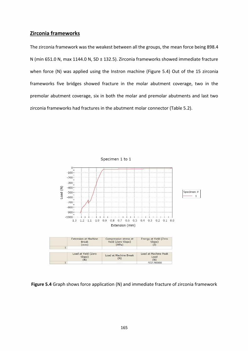
165
Zirconia frameworks
The zirconia framework was the weakest between all the groups, the mean force being 898.4
N (min 651.0 N, max 1144.0 N, SD ± 132.5). Zirconia frameworks showed immediate fracture
when force (N) was applied using the Instron machine (Figure 5.4) Out of the 15 zirconia
frameworks five bridges showed fracture in the molar abutment coverage, two in the
premolar abutment coverage, six in both the molar and premolar abutments and last two
zirconia frameworks had fractures in the abutment molar connector (Table 5.2).
Figure 5.4 Graph shows force application (N) and immediate fracture of zirconia framework
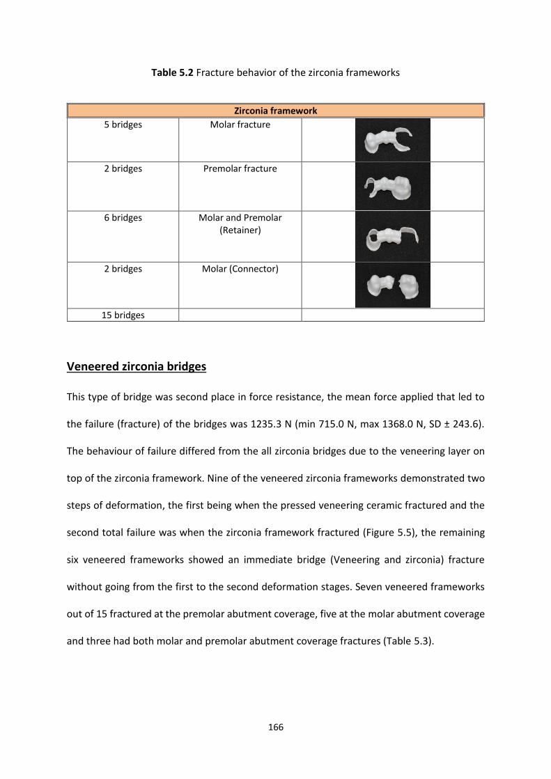
166
Table 5.2 Fracture behavior of the zirconia frameworks
Veneered zirconia bridges
This type of bridge was second place in force resistance, the mean force applied that led to
the failure (fracture) of the bridges was 1235.3 N (min 715.0 N, max 1368.0 N, SD ± 243.6).
The behaviour of failure differed from the all zirconia bridges due to the veneering layer on
top of the zirconia framework. Nine of the veneered zirconia frameworks demonstrated two
steps of deformation, the first being when the pressed veneering ceramic fractured and the
second total failure was when the zirconia framework fractured (Figure 5.5), the remaining
six veneered frameworks showed an immediate bridge (Veneering and zirconia) fracture
without going from the first to the second deformation stages. Seven veneered frameworks
out of 15 fractured at the premolar abutment coverage, five at the molar abutment coverage
and three had both molar and premolar abutment coverage fractures (Table 5.3).
Zirconia framework
5 bridges Molar fracture
2 bridges Premolar fracture
6 bridges Molar and Premolar
(Retainer)
2 bridges Molar (Connector)
15 bridges
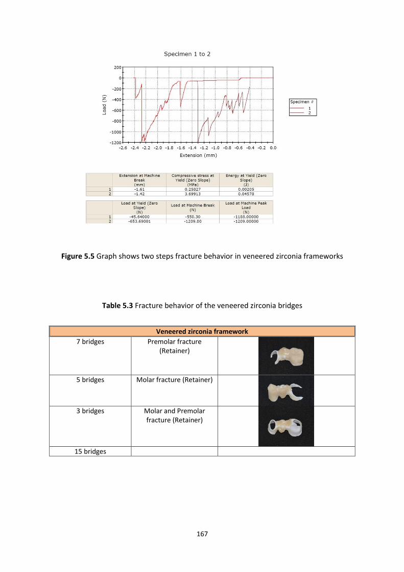
167
Figure 5.5 Graph shows two steps fracture behavior in veneered zirconia frameworks
Table 5.3 Fracture behavior of the veneered zirconia bridges
Veneered zirconia framework
7 bridges Premolar fracture (Retainer)
5 bridges Molar fracture (Retainer)
3 bridges Molar and Premolar
fracture (Retainer)
15 bridges
168
5.5 Discussion
In this laboratory study three types of zirconia-based restoration were fabricated (all-zirconia,
zirconia framework and veneered zirconia frameworks) to fit ideally prepared teeth and
provide a restoration with full anatomical features to simulate the clinical conditions, unlike
some previous studies which have used metal cylinders (Sundh and Sjogren, 2004, Sundh et
al., 2005, Kanat et al., 2014a) with no anatomic form and un-contoured zirconia blocks (Sundh
and Sjogren, 2004). This is important as the irregularities encountered in a prepared tooth
and a fully contoured restoration may impact upon the thickness of the materials at various
sites within the restoration, produce areas of greater stress concentration especially at cusp
tips and might influence crack propagation (Oh and Anusavice, 2002). As such, the results
from this study may be considered to more closely represent the clinical situation. However
there are some obvious differences compared to a study that perhaps was conducted in situ;
prepared teeth would consist of dentine and a pulp with pain receptors and slung in a
periodontal ligament which functions in a synergistic manner and acts as a shock absorber
when force is applied on the tooth in the real clinical situation (Ho et al., 2004, Naveh et al.,
2012). These are all factors that might account for differences between the results from this
laboratory study and that from a clinical or in situ study. In theory an in situ study would be
possible where teeth that are prepared for a bridge receive three bridges (as in this study)
and the patient applies occlusal loading, measured with a strain gauge, until failure of the
bridge. Not only would this be un-ethical due to the potential damage and harm to the patient
it is unlikely that the patient would be able to apply the forces reached for failure in this study
(see later in this discussion).
169
The three types of restoration investigated in this laboratory study were chosen, principally
because the zirconia framework and all zirconia bridges had a different thickness, allowing
investigation of the impact this would have on strength. In addition, it has been argued that
veneering can influence the strength of the restoration and mode of failure which has been
related to the thicknesses of the restoration core (metal and ceramic) and veneering ceramic
together (Lund and Barber, 1992, Wakabayashi and Anusavice, 2000). The un-veneered and
veneered zirconia frameworks therefore allowed investigation of the impact that ceramic
veneering has on longer span three unit bridges.
A 0.5 mm thickness of zirconia is considered to be adequate for sufficient strength of zirconia
to withstand normal occlusal forces and adequate for ceramic veneering (Sundh and Sjogren,
2004). The thickness of the zirconia frameworks can be altered in the CAD software, but more
often than not the CAD CAM system default settings are used, which range from a uniform
thickness of 0.5 mm to 0.8 mm. In the clinical situation, a heavier occlusal reduction in the
area of a cusp tip for example, could, with a uniform coping thickness, lead to a thick layer of
unsupported veneering ceramic which is inherently weak and this may account for some of
the veneering ceramic failure that are seen clinically (Vult von Steyern et al., 2005, Larsson et
al., 2007). In this study, whilst a uniform 0.7 mm thickness was used for the framework
retainer, the problem of unsupported ceramic was avoided due to the ideal tooth preparation
following the contours of the occlusal surface of the tooth and reducing the tooth occlusally
by the recommended 1.5 – 2.0 mm (Blair et al., 2002). The standardised veneering process
also ensured that the veneering ceramic on all veneered bridges were of an identical
thickness.
170
Previous studies that have measured the load required to fracture all ceramic zirconia based
restorations are detailed in Table 5.4, and surprisingly the results demonstrate a wide range,
varying from as low as 346.0 N to as high as 6262.7 N (Tinschert et al., 2001a, Sundh and
Sjogren, 2004, Sundh et al., 2005, Fischer et al., 2007, Aboushelib et al., 2008, Beuer et al.,
2009f, Kanat et al., 2014a). This might be due to many factors such as the thickness of
veneering ceramic, anatomical variation of the veneering ceramic, loading method
(Aboushelib et al., 2008) the number of units, load application location and angulation. This
makes it impossible to compare the forces from the different studies in Table 5.4. The forces
recorded for failure in this laboratory study fell within the range of the previously published
work (all zirconia 1858.5 N (min 1348.0 N, max 2968.0 N, SD ± 430.5), zirconia frameworks
898.4 N (min 651.0 N, max 1144.0 N, SD ± 132.5) and finally veneered zirconia frameworks
1235.3 N (min 715.0 N, max 1368.0 N, SD ± 243.6)) but this is unsurprising considering the
range from the previously published literature.
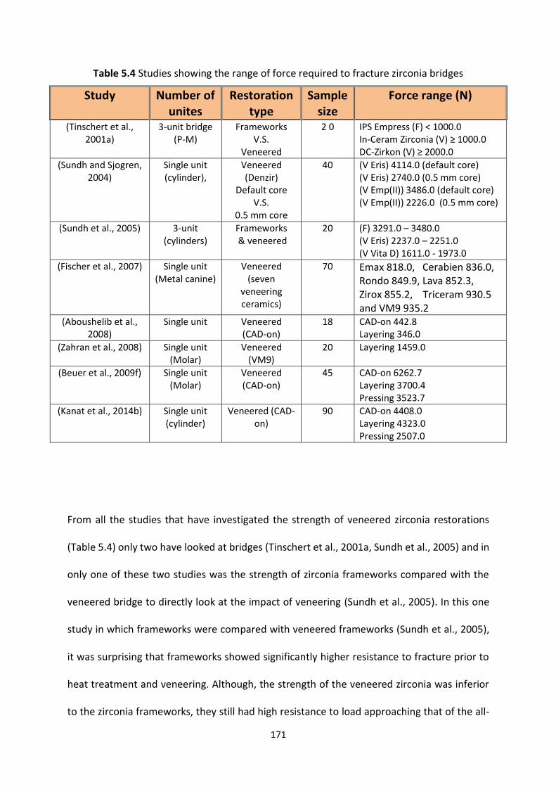
171
Table 5.4 Studies showing the range of force required to fracture zirconia bridges
From all the studies that have investigated the strength of veneered zirconia restorations
(Table 5.4) only two have looked at bridges (Tinschert et al., 2001a, Sundh et al., 2005) and in
only one of these two studies was the strength of zirconia frameworks compared with the
veneered bridge to directly look at the impact of veneering (Sundh et al., 2005). In this one
study in which frameworks were compared with veneered frameworks (Sundh et al., 2005),
it was surprising that frameworks showed significantly higher resistance to fracture prior to
heat treatment and veneering. Although, the strength of the veneered zirconia was inferior
to the zirconia frameworks, they still had high resistance to load approaching that of the all-
Study Number of unites
Restoration type
Sample size
Force range (N)
(Tinschert et al., 2001a)
3-unit bridge (P-M)
Frameworks V.S.
Veneered
2 0 IPS Empress (F) < 1000.0 In-Ceram Zirconia (V) ≥ 1000.0 DC-Zirkon (V) ≥ 2000.0
(Sundh and Sjogren, 2004)
Single unit (cylinder),
Veneered (Denzir)
Default core V.S.
0.5 mm core
40 (V Eris) 4114.0 (default core) (V Eris) 2740.0 (0.5 mm core) (V Emp(II)) 3486.0 (default core) (V Emp(II)) 2226.0 (0.5 mm core)
(Sundh et al., 2005) 3-unit (cylinders)
Frameworks & veneered
20 (F) 3291.0 – 3480.0 (V Eris) 2237.0 – 2251.0 (V Vita D) 1611.0 - 1973.0
(Fischer et al., 2007) Single unit (Metal canine)
Veneered (seven
veneering ceramics)
70 Emax 818.0, Cerabien 836.0, Rondo 849.9, Lava 852.3, Zirox 855.2, Triceram 930.5 and VM9 935.2
(Aboushelib et al., 2008)
Single unit
Veneered (CAD-on)
18 CAD-on 442.8 Layering 346.0
(Zahran et al., 2008) Single unit (Molar)
Veneered (VM9)
20 Layering 1459.0
(Beuer et al., 2009f) Single unit (Molar)
Veneered (CAD-on)
45 CAD-on 6262.7 Layering 3700.4 Pressing 3523.7
(Kanat et al., 2014b) Single unit (cylinder)
Veneered (CAD-on)
90 CAD-on 4408.0 Layering 4323.0 Pressing 2507.0

172
zirconia bridges in this study. This was totally the opposite to the results of this laboratory
study, which found that the strength of the framework and bridges improved significantly
when the veneering ceramic had been added. This difference may be attributed to the fact
that the zirconia in this study was milled in its pre-sintered state, and became stronger during
subsequent firings, and in the study by Sundh et al., (2005) the frameworks were milled in a
sintered state where further firings weakened the bridges.
The results from the second study are difficult to interpret as it did not compare like with like;
the strength of two veneered zirconia frameworks (In-Ceram Zirconia and DC-Zirkon) were
compared with that of un-veneered leucite reinforced porcelain frameworks (Tinschert et al.,
2001a). The results showed that veneered zirconia had higher resistance to fracture loads
compared with the leucite reinforced ceramic, and whilst interesting the comparison is not
logical, because the frameworks are made with completely different materials with inherent
differences in strengths and a comparison with veneered leucite frameworks was also not
made. This study did not provide the reader with absolute fracture loads but instead gave
readings above or below a certain threshold, but comparing the results with that of this study
the results for the veneered zirconia (In-Ceram) frame works were broadly in agreement with
that of this laboratory study.
The other studies in Table 5.4 investigated the strength of single unit veneered zirconia
restorations only with none comparing the strength of the coping only with that of the
veneered coping as in this study; the loads to failure ranged between 346.0 N and 6262.7 N.
The wide variation in loads may be explained by the different types of veneering ceramics
used, with all conventionally (layering technique) veneered restorations having a high
resistance to fracture loads (818.0 N to 4114.0 N (Sundh and Sjogren, 2004, Fischer et al.,
173
2007)), different thicknesses of zirconia core (Sundh and Sjogren, 2004), and different
veneering techniques (CAD-on 442.8 N to 6262.7 N, layering 346.0 N to 4323.0 N and pressing
2507.0 N to 3523.7 N (Aboushelib et al., 2008, Beuer et al., 2009f, Kanat et al., 2014a)).
One study stands out as having significantly lower strength than the others and that obtained
in this study (CAD-on 442.8 N and layering 346.0 N) (Aboushelib et al., 2008). In that study the
CAD-on and layering techniques were compared and the reason for the lower strength are
difficult to explain, other than fact that the fracture strength test used resin dies as a base for
the investigated specimens and a sheet of tough rubber (0.5 mm) perhaps creating a greater
wedging effect between cusps; what constitutes failure is also not clear.
It is interesting to note that the mean force required to fracture the veneered zirconia
frameworks (1235.3 N) in this study, which were veneered using the pressing technique, was
lower than that previously reported for single unit veneered restorations also veneered using
the pressing technique (2507.0 N – 3523.7 N) (Beuer et al., 2009f, Kanat et al., 2014a). The
difference is most likely to be due to the length of the span in the bridges compared to crowns
where potential flexure of the bridge, at thinner sections such as the connector (or retainer)
can lead to earlier failure (Larsson et al., 2007). In the third laboratory study of this thesis the
effect that increasing the span of bridges from three unit to four unit had on internal and
marginal fit was investigated, however the effect this would have on bridge strength was not
investigated. This together with the connector diameter could indeed impact on the strength
of the bridge and merits further work.
The results of this study (Figure 5.6) and the previous studies in Table 5.4, clearly show that
all zirconia, zirconia frameworks and veneered zirconia bridges, with their variation in zirconia
thickness, have a mean fracture load (2968.0 N, 898.4 N and 1235.3 N respectively) that is
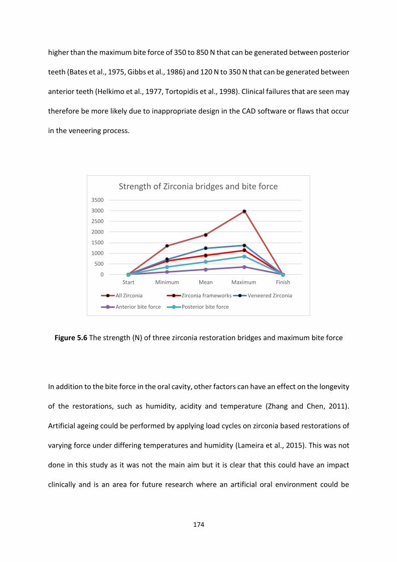
174
higher than the maximum bite force of 350 to 850 N that can be generated between posterior
teeth (Bates et al., 1975, Gibbs et al., 1986) and 120 N to 350 N that can be generated between
anterior teeth (Helkimo et al., 1977, Tortopidis et al., 1998). Clinical failures that are seen may
therefore be more likely due to inappropriate design in the CAD software or flaws that occur
in the veneering process.
Figure 5.6 The strength (N) of three zirconia restoration bridges and maximum bite force
In addition to the bite force in the oral cavity, other factors can have an effect on the longevity
of the restorations, such as humidity, acidity and temperature (Zhang and Chen, 2011).
Artificial ageing could be performed by applying load cycles on zirconia based restorations of
varying force under differing temperatures and humidity (Lameira et al., 2015). This was not
done in this study as it was not the main aim but it is clear that this could have an impact
clinically and is an area for future research where an artificial oral environment could be
0
500
1000
1500
2000
2500
3000
3500
Start Minimum Mean Maximum Finish
Strength of Zirconia bridges and bite force
All Zirconia Zirconia frameworks Veneered Zirconia
Anterior bite force Posterior bite force
175
created including the use of teeth with dentine and periodontal ligament simulation and cyclic
loading in more than just an axial direction (Qutieshat, 2016).
Catastrophic failure as in this study is not the only mode of failure, another problem
encountered is smaller cracking or chipping of the veneering ceramics from the core material
(Zhang et al., 2012). This may result from residual stress that can develop during the
manufacturing process, which will lead to crack propagation under functional load and
chipping of the veneering ceramic (Swain, 2009). It has been reported in a three year and five
year follow-up study that chipping of ceramic from zirconia bridge frameworks reaches a
prevalence of 13.0 % and 15.2 % respectively (Sailer et al., 2006, Sailer et al., 2007a). On the
other hand metal ceramic restorations showed lower rates of veneering ceramic chipping (2.7
% to 5.5 %) over an observation period of 10 to 15 years (Valderhaug, 1991, Guess et al.,
2008). Whilst the incidence of chipping is greater in the zirconia based restorations compared
with metal ceramic restorations, such chipping may not lead to an un-aesthetic restoration;
chipping of the veneering ceramic that happens with metal ceramic restorations will either
show the opaque ceramic layer or the metallic core, for zirconia restorations the coping or
framework is tooth coloured.
It has clearly been shown that CAD CAM systems can fabricate zirconia cores in relatively thin
sections (0.5 mm to 0.8 mm) which can withstand high occlusal loads when veneered
(Tinschert et al., 2001a, Sundh and Sjogren, 2004, Sundh et al., 2005, Zahran et al., 2008).
Whilst this study has shown that the all zirconia bridges produced the highest fracture
strength, even the thinner frameworks were able to withstand forces higher than occlusal
forces achieved between anterior teeth. This raises the question, is it possible to minimally
prepare anterior teeth for fully anatomical zirconia restorations with adequate aesthetics?
176
Advances and improvements in stains and techniques for zirconia can now lead to better
aesthetics than was originally achieved and this therefore is a real possibility and needs
further work.
5.6 Conclusion
Within the limitations in this study, the following conclusion scan be drawn:
1. Zirconia based restorations showed high resistance to vertical loads.
2. Veneering ceramic increased the strength of zirconia framework.
3. All the zirconia based restorations, including the thin section frameworks, can withstand
occlusal loads.
177
Chapter 6
Laboratory study 5
Digital Impression versus
Conventional impression
178
Laboratory study 5
Digital Impression versus Conventional impression
6.1 Introduction
Conventional impression techniques using an impression tray and impression material have
been common practice for a many decades, aiming to produce a stone cast which transfers
accurate information from the patient’s mouth to the laboratory, and as such has been the
gold standard (Henkel, 2007, Lee et al., 2015). Whilst widely used, it is important to follow
several steps to produce an accurate dental impression, such as choosing the correct material
and technique for the task in hand (Nissan et al., 2000, Chen et al., 2004, Levartovsky et al.,
2014) This, in turn, will lead to an accurate dental stone cast and dental restoration (Hung et
al., 1992, Maruo et al., 2007). Even by following all the appropriate steps and instruction it is
still subjected to ‘guesswork’ in that once the impression is cast the stone model produced
may not be fit for purpose, even though the impression subjectively looked satisfactory. In
addition, conventional impressions may be uncomfortable for some patients (gag reflex) and
the armamentarium can be expensive (Garg, 2008).
Since the 1950s elastomeric impression materials have been used routinely for indirect
restorations (Christensen, 1997, Maruo et al., 2007) due to their high accuracy, dimensional
stability, excellent elastic recovery, minimum permanent distortion and good tear strength
(Bindra and Heath, 1997, Christensen, 1997, Mandikos, 1998, Brosky et al., 2002).
179
Since the introduction of dental CAD CAM as a technology that produces highly accurate and
precise indirect restorations, there has been an increased need for an accurate, easy and less
time consuming impression (Miyazaki et al., 2009). The first CAD CAM system (CEREC) that
was introduced by W. Mörmann and M. Brandestini in the 1980s, had an intraoral scanner
which picked up information (cavity/ tooth preparation) from the patient’s tooth and relayed
this to the CAD system (Mörmann et al., 1989). In this way the digital impression can eliminate
some of the problems that occur with conventional impressions such as: improper impression
tray selection, separation of the impression material from the tray, distortion of the
impression material (due to disinfection or prolonged storage), infection control (disinfecting
the impression), and, finally, compatibility of dental stone with the impression material
(Christensen, 2009, Almortadi and Chadwick, 2010).
Today, there are many digital impression devices available commercially and the digital
impression concept is rapidly growing with each new device having its own specification. This
has made it important to compare digital impressions to conventional impressions, and to
compare impressions obtained with different intraoral scanners.
6.2 Aims and objectives
The aim of this study was to compare the accuracy (internal and marginal) of fit of three unit
bridges designed and manufactured using a CAD CAM system using information from a
conventional impression technique (scanned stone models) and digital intra oral scan.
180
6.3 Material and Methods
Tooth preparation and Quality control
The ideally prepared and quality controlled tooth preparations used in the first laboratory
study were also used in this study.
Digital Impression, conventional impression and all zirconia bridges
manufacture
The digital file of the tooth preparations obtained in the first laboratory study was used to
produce 30 identical non-sectioned Stereolithography models (SLA models, In’Tech
Industries, Inc. USA). Each model was treated as an independent patient case and had a
unique number to differentiate it from the other models. The 30 models (cases) were then
randomly divided into two groups, 15 were assigned to a conventional silicone putty and wash
impression technique and 15 were assigned to a digital impression (LAVA C.O.S).
Digital impression
Each of the 15 SLA models assigned to the digital impression group were scanned using the
Lava C.O.S (3M ESPE, Seefeld, Germany) adopting the same steps that were used and
described in the first laboratory study so creating 15 digital impression files, one for each
independent case (no extra SLA models were ordered) (See the first laboratory study
materials and methods).
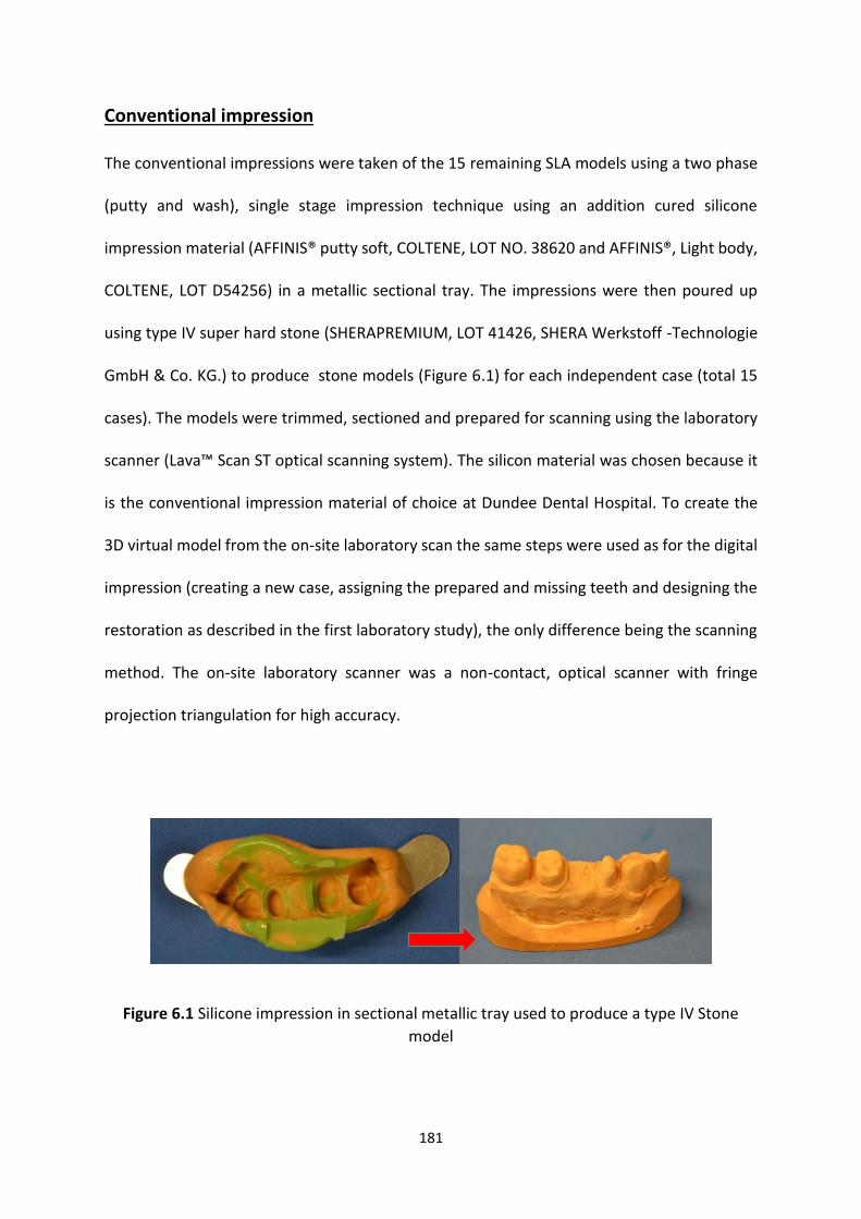
181
Conventional impression
The conventional impressions were taken of the 15 remaining SLA models using a two phase
(putty and wash), single stage impression technique using an addition cured silicone
impression material (AFFINIS® putty soft, COLTENE, LOT NO. 38620 and AFFINIS®, Light body,
COLTENE, LOT D54256) in a metallic sectional tray. The impressions were then poured up
using type IV super hard stone (SHERAPREMIUM, LOT 41426, SHERA Werkstoff -Technologie
GmbH & Co. KG.) to produce stone models (Figure 6.1) for each independent case (total 15
cases). The models were trimmed, sectioned and prepared for scanning using the laboratory
scanner (Lava™ Scan ST optical scanning system). The silicon material was chosen because it
is the conventional impression material of choice at Dundee Dental Hospital. To create the
3D virtual model from the on-site laboratory scan the same steps were used as for the digital
impression (creating a new case, assigning the prepared and missing teeth and designing the
restoration as described in the first laboratory study), the only difference being the scanning
method. The on-site laboratory scanner was a non-contact, optical scanner with fringe
projection triangulation for high accuracy.
Figure 6.1 Silicone impression in sectional metallic tray used to produce a type IV Stone
model

182
Bridge design and fabrication
The data captured for each model (15 SLA models and 15 stone models obtained from the
conventional silicone impressions) were used to design the corresponding all zirconia bridges
in the CAD system. The same settings were used for both types of impression capture to
ensure that the bridges were identical from a production point of view, with the only
difference being the impression and scanning method (die spacer 0.095 mm extra vertical
(occlusal), 0.075 mm extra horizontal (buccal, mesial, distal and lingual) and minimum coping
thickness 0.5 mm). This process allowed the manufacture of 30 three unit all zirconia bridges
for the corresponding independent case using a five axis CAM milling machine (Lava™ CNC
500 Milling System, 3M ESPE) and dry milling process. Semi-sintered zirconia multi blocks
were used to fabricate the all zirconia FPDs (3M ESPE, Seefeld, Germany, LOT No. 470281,
LOT No. 472678 and LOT No. 472678). The semi-sintered all zirconia bridges were placed in a
custom furnace (Lava™ furnace 200, (3M ESPE, Seefeld, Germany) to fully sinter the zirconia
framework at 1500°C for 4 hours 48 minutes (LAVA 1500, Non-shaded).
Restoration cementation
The 30 bridges from both groups were cemented permanently to their designated models.
The force application device was used to cement the 30 bridges (cementation force = 30.0 N),
using the same steps that were developed and adopted in the second laboratory study (See
laboratory study two). RelyX™ Unicem 2 Clicker™ (3M ESPE, Seefeld, Germany, LOT No.
517676) self-adhesive Universal Resin Cement was used as the luting cement as described in
the second laboratory study.
183
Preparation for, and SEM observation
The same preparation for sectioning and SEM technique used in the second laboratory study
was used in this study for analysis of the internal and marginal fit of the dental restorations
made using the two impression technique.
Statistical analysis
The internal and marginal cement gaps were recorded (pooled data from both abutment
retainers - premolar and molar) for the all zirconia bridges manufactured from each
impression technique. One way ANOVA was used to assess whether there were any
statistically significant differences in the internal and marginal fits of the bridges produced
using the two impression techniques. A t-test was used to compare the internal and marginal
fit of the two abutment - retainers types (pre-molar and molar) to assess if there was any
significant difference between the abutment – retainer types of the bridges made using the
same impression method and between the abutment – retainer type from the different
impression methods (IBM® SPSS® 21).
6.4 Results
Internal fit
The mean internal fit for the all zirconia bridges made using the conventional impression was
98.6 µm (min 90.0 µm, max 120.0 µm and SD ± 7.2) and for the all zirconia bridges made using
the digital impression it was 88.6 µm (min 80.0 µm, max 109.0 µm and SD ± 6.9). One way
184
ANOVA was used to compare the internal fit and to check if there was any significant
difference between the two types of impressions. The result showed that there was a
significant difference between the bridges made from the two impression techniques (p =
0.00). The bridges made using the conventional impression showed a greater internal gap
(Figure 6.2).
Molar abutment-retainer and premolar abutment-retainer
The molar abutment-retainer fit was compared with the premolar abutment-retainers for the
bridges made using the same impression (Conventional or Digital). In addition the molar
abutment-retainer fit of the bridges made from the two impression techniques were
compared as was the premolar abutment-retainers to determine whether there was any
statistical significant different between the two impression techniques for one abutment
tooth type using the t test.
Conventional impression technique
For the bridges made using the conventional impression technique the mean value of the
internal fit of the molar abutment-retainers was 98.6 µm (min 91.0 µm, max 119.0 µm and
SD ± 7.2) and for the premolar the mean was 98.5 µm (min 92.0 µm, max 119.0 µm and SD ±
7.1). No statistically significant difference was found in relation to both premolar and molar
abutment - retainers internal fit when a conventional impression was taken (one way ANOVA,
p = 0.3).
185
Digital impression technique
For the bridges made using the digital impression the mean value of the internal fit of the
molar abutment-retainer was 88.6 µm (min 82.0 µm, max 109.0 µm and SD ± 6.1) and the
premolar abutment-retainer the mean value was 88.6 µm (min 80.0 µm, max 109.0 µm and
SD ± 6.9). There was no statistically significant difference found in relation to both premolar
and molar abutment-retainers internal fit when a digital impression was taken (one way
ANOVA, p = 0.3).
Conventional versus Digital abutment - retainers
A t-test was applied to the internal fit of the molar abutment - retainers of the bridges
obtained from the two different impression techniques, the results indicated that there was
a statistically significant difference (p ≤ 0.05). Similarly the results obtained for the internal fit
of the premolar abutment-retainers for the bridges obtained from the two different types of
impression techniques indicated a statistically significant difference (p ≤ 0.05) with the fit
being closer for the bridges obtained from the digital impression.
Marginal fit
The mean marginal fit of the all zirconia bridges that were made using the conventional
impression was 37.9 µm (min 36.0 µm, max 40.0 µm and SD ± 0.7) and for the digital
impression restoration it was 28.2 µm (min 26.0 µm, max 29.0 µm and SD ± 0.7). One way
ANOVA showed that there was a significant difference between the bridges made using the

186
two types of impressions (p ≤ 0.05). The results showed that the bridges made using the
conventional impression technique had greater marginal gap (Figure 6.2).
Molar abutment-retainer and premolar abutment-retainer
The same comparisons that were made for the internal fit measurements were applied to the
marginal fit measurements using One-way ANOVA, namely the molar abutment-retainers fit
and premolar abutment-retainers fit for the bridges made using the same impression
technique and from the different types of impression techniques were compared.
Conventional impression technique
For the bridges made using the conventional impression technique the mean value of the
marginal fit of the molar abutment-retainers was 37.9 µm (min 37.0 µm, max 40.0 µm and SD
± 0.8) and for the premolar the mean was 37.8 µm (min 37.0 µm, max 39.0 µm and SD ± 0.7).
One-way ANOVA results showed that there was no statistically significant difference between
the molar and premolar abutment-retainers (p = 0.4).
Digital impression technique
For the bridges made using the digital impression, the mean value of marginal fit of the molar
abutment - retainer was 28.2 µm (min 27.0 µm, max 29.0 µm and SD ± 0.7) and the premolar
the mean value was 28.1 µm (min 27.0 µm, max 29.0 µm and SD ± 0.7). One-way ANOVA
results showed that there was no statistically significant difference (p = 0.3) between the
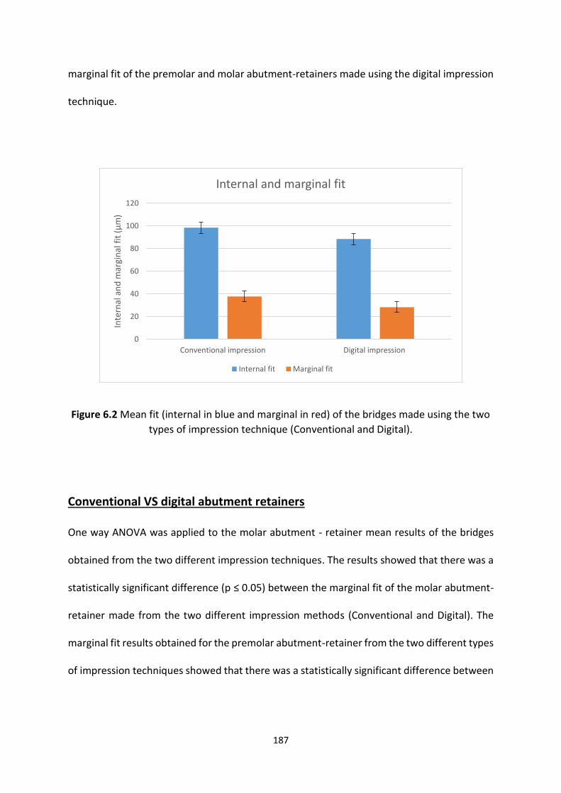
187
marginal fit of the premolar and molar abutment-retainers made using the digital impression
technique.
Figure 6.2 Mean fit (internal in blue and marginal in red) of the bridges made using the two
types of impression technique (Conventional and Digital).
Conventional VS digital abutment retainers
One way ANOVA was applied to the molar abutment - retainer mean results of the bridges
obtained from the two different impression techniques. The results showed that there was a
statistically significant difference (p ≤ 0.05) between the marginal fit of the molar abutment-
retainer made from the two different impression methods (Conventional and Digital). The
marginal fit results obtained for the premolar abutment-retainer from the two different types
of impression techniques showed that there was a statistically significant difference between
0
20
40
60
80
100
120
Conventional impression Digital impression
Inte
rnal
an
d m
argi
nal
fit
(µ
m)
Internal and marginal fit
Internal fit Marginal fit
188
the two retainers (p ≤ 0.05)), with the conventional impression in both cases resulting in
greater marginal gaps.
6.5 Discussion
Conventional impressions can be affected by many clinical factors such as, impression
technique, impression material, finish-line location, saliva flow, patients mouth opening
(accessibility) and periodontal condition (Syrek et al., 2010). Some of these factors can also
affect intraoral scanning, and hence can have an impact on the final impression (conventional
or digital) which will affect the fit of the final restoration. Therefore, this laboratory study
compared silicone based conventional impression with digital impression (intraoral scanner)
under ideal conditions, to investigate whether the impression technique could impact upon
the internal and marginal fit of three unit all zirconia bridges. The previously mentioned
confounding clinical factors are not applicable for this laboratory study, thus reducing the
number of variables that could have an effect on the impression (digital and conventional) of
the three unit all zirconia bridges, leaving the impression technique as the only variable.
The conventional impression material used in this study was a silicone-based impression
material, because they are the most widely used in dentistry and for the material properties
outlined in the introduction (Vitti et al., 2013) namely high accuracy, dimensional stability,
excellent elastic recovery, minimum permanent distortion and good tear strength (Bindra and
Heath, 1997, Christensen, 1997, Mandikos, 1998, Brosky et al., 2002). The conventional
impressions were made using a sectional metallic tray which ensured more rigidity and
support to the impression material during impression taking and stone model pouring. This is
189
important as tray selection and rigidity of the tray could have had an influence on the accuracy
of the impression which will affect the final restoration (Hoyos and Soderholm, 2011). As such
the conventional impressions were optimal. Despite this, the results of this laboratory study
showed a statistically significant difference between the two techniques, with the digital
impressions producing restorations with better internal and marginal fit (88.6 µm, 28.2 µm
respectively) compared to the conventional impression (98.6 µm, 37.6 µm respectively).
However, both techniques resulted in restorations with fit within the range that is thought to
be clinically acceptable (McLean and von Fraunhofer, 1971, Martinez-Rus et al., 2011).
The results obtained from this laboratory study are in agreement with studies published since
the conception of this study (2011), which compared conventional impressions with digital
impressions (Table 6.1).

190
Table 6.1 Studies comparing digital impressions and conventional impressions, digital (D) and conventional (C) in relation to marginal fit.
Study Model Digital / Conventional
Results for Marginal Fit (mean)
Measurment Comments
(Henkel, 2007) Patients
Crown
iTero / conventional Questionaire Digital impression is promising and the technology will rapidly increase
(Syrek et al., 2010) Patients
Crown
Lava COS / conventional (2 step silicone)
(D) 49.0 µm / (C) 71.0 µm
Impression/ Microscope
Digital superior to conventional
(van der Meer et al., 2012) Model
Implant
CEREC, iTERO, Lava Rapid form software
Lava had the best precision
(Seelbach et al., 2013) Model
Crown
CEREC, Lava, iTero & conventional (Silicone) 1 & 2 step
((D) 88.0 µm, 29.0 µm, 50.0 µm,
(C) 35.0-56.0 µm, respectively)
Microscope Digital and conventional are both accurate
(Guth et al., 2013) Model
Crown
Lava/ conventional (polyether)
(D)17.0 µm and (C) 23.0 - 36.0 µm
Inspection Software
Digital superior to conventional
(Lee and Gallucci, 2013) Model iTero/ conventional (silicone) Questionnaire Digital superior to conventional
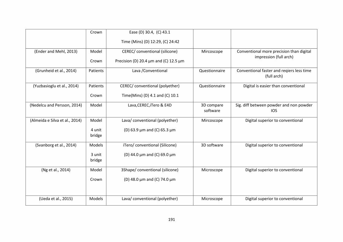
191
Crown Ease (D) 30.4, (C) 43.1
Time (Mins) (D) 12:29, (C) 24:42
(Ender and Mehl, 2013) Model
Crown
CEREC/ conventional (silicone)
Precision (D) 20.4 µm and (C) 12.5 µm
Mircoscope Conventional more precision than digital impression (full arch)
(Grunheid et al., 2014) Patients Lava /Conventional Questionnaire Conventional faster and reqiers less time (full arch)
(Yuzbasioglu et al., 2014) Patients
Crown
CEREC/ conventional (polyether)
Time(Mins) (D) 4.1 and (C) 10.1
Questionnaire Digital is easier than conventional
(Nedelcu and Persson, 2014) Model Lava,CEREC,iTero & E4D 3D compare software
Sig. diff between powder and non powder IOS
(Almeida e Silva et al., 2014) Model
4 unit bridge
Lava/ conventional (polyether)
(D) 63.9 µm and (C) 65.3 µm
Mircoscope Digital superior to conventional
(Svanborg et al., 2014) Models
3 unit bridge
iTero/ conventional (Silicone)
(D) 44.0 µm and (C) 69.0 µm
3D software Digital superior to conventional
(Ng et al., 2014) Model
Crown
3Shape/ conventional (silicone)
(D) 48.0 µm and (C) 74.0 µm
Microscope Digital superior to conventional
(Ueda et al., 2015) Models Lava/ conventional (polyether) Microscope Digital superior to conventional

192
4 unit bridge
(D) 51.5 µm and (C) 72.9 µm
(Pradies et al., 2015) Patients
Crown
Lava/ conventional (Silicone)
(D) 76.3 µm and (C) 91.5 µm
Steremicroscope Digital superior to conventional
193
The studies in Table 6.1 have investigated the accuracy of intraoral scanners, either by
comparing different makes of intraoral scanners (van der Meer et al., 2012, Nedelcu and
Persson, 2014), or by comparing one or more intraoral scanners with conventional
impression (Henkel, 2007, Syrek et al., 2010, Guth et al., 2013, Lee and Gallucci, 2013,
Ender and Mehl, 2013, Seelbach et al., 2013, Yuzbasioglu et al., 2014, Almeida e Silva et
al., 2014, Svanborg et al., 2014, Ng et al., 2014, Ueda et al., 2015, Pradies et al., 2015).
All but one of the previous studies are in agreement with the results from this laboratory
study, concluding that digital impression is considered superior to conventional
impression.
From all the studies in Table 6.1, only two studies concluded that a conventional
impression is superior to a digital impression when used for full arch impressions (Ender
and Mehl, 2013, Grunheid et al., 2014). There may be a number of reasons for this, for
example are: un-experienced operator in using the intraoral scanner, measurement
method and/or span length. It should be noted that these are the only studies where
full arch impressions were investigated and it is recognised clinically that taking an
accurate full arch conventional impression is demanding as it is done in one step and the
impression tray has to be seated before the impression material starts to set. Whilst this
is true, in the laboratory at room temperature, greater time is available for accurate
working and access is unimpeded as it would be intra-orally with tongue and soft tissues
etc. This may together with operator familiarity with the technique, explain the superior
accuracy of the conventional impression (Ender and Mehl, 2013, Grunheid et al., 2014).
For the digital impression, on the other hand, the wand travels over the arch at a fixed
distance from the teeth in all directions (labial, palatal, anterior and posterior). Using a
laboratory model also facilitates this technique but unfamiliarity with the technique
194
together with the distance the wand has to travel over (causing operator fatigue and
poor stability) may explain why in the study by Ender and Mehl (2013) the digital
impression was inferior. The difference in accuracy was greatest posteriorly, reaching a
difference of around 170.0 µm, supporting the latter suppositions.
Single crowns were the most commonly investigated restoration in the previous studies,
except for the study by van der Meer et al., (2012) who investigated the precision of
digital impressions on dental implants (van der Meer et al., 2012), and three studies that
investigated digital impressions and conventional impressions for multiple unit bridges
(three and four unit bridges) (Svanborg et al., 2014, Almeida e Silva et al., 2014, Ueda et
al., 2015). Concentrating on the results from the studies on bridges for comparison with
the results from this study, the mean marginal fit obtained from the three studies for
the digital impression ranged from 44.0 µm – 63.9 µm and for the conventional
impression mean results ranged between 65.3 µm - 72.9 µm. The mean results for
marginal fit in this laboratory study (digital impressions 28.2 µm conventional
impression 37.6 µm) were superior (better fit) despite the fact that two of the previous
studies also used the Lava system on similar span bridges. The difference may actually
be down to the way in which the marginal gap was measured with two using a replica
impression technique and microscope, which may not be as accurate as sectioning and
investigation with the SEM as in this study.
Seelbach et al (2013), investigated the difference between three types of digital intraoral
scanner (CEREC, iTero and Lava) with two techniques to obtain a conventional
impression (single step and two step). The mean results for internal and marginal fit for
each group were as follows, CEREC 88.0 µm and 30.0 µm respectively, Lava COS 29.0 µm
and 48.0 µm, iTero 50.0 µm and 41.0 µm, single step conventional impression (Lava
195
zirconia, Cera E) 36.0 µm, 44.0 µm and 33.0 µm, 38.0 µm respectively and, finally, the
two-step conventional impression (Lava zirconia, Cera E) 35.0 µm, 56.0 µm and 60.0 µm,
68.0 µm respectively, it was concluded that the digital impression and conventional
impressions (single and two step) all resulted in zirconia restorations with an acceptable
fit, and that the Lava system resulted in the best fit of zirconia restorations for both
digital and conventional impression techniques (Seelbach et al., 2013). It is interesting
to note that the result from this study are very similar to those obtained for crowns
made with the CEREC machine in the Seelbach et al. study (Seelbach et al., 2013). For
both the iTero and CEREC crowns in the Seelbach study and the Lava bridges in this study
the internal fit is higher than the marginal fit as this is generally what would be expected
with the default settings on the CAD CAM machines, or even when these are customised
as one would want the marginal gap to be as small as possible. It is therefore unusual to
find that the Lava crowns in the Seelbach study had a marginal gap higher than that of
the internal fit, which is the reverse to that found in this study. This is difficult to explain
and unclear in the publication, but may be due to the technician/researcher altering the
default settings in such a way or due to the fact that the marginal gap was not measured
at the true periphery or external margin of the restoration.
It is often debated as to which technique, conventional or digital impression, is easier
and user friendly for both the dentist and the patient. As a result this has been the focus
of two papers by Lee and Gallucci, 2013 and Lee et al. (2013) (Lee and Gallucci, 2013,
Lee et al., 2013b) in which both types of impression were taken for a single implant
model. In the former study only dental students’ views were evaluated using Visual
Analogue Scales (VAS) and the overall time to take the impression and any additional
time for retakes were evaluated. Time is obviously an important factor because it can
196
be stressful for both the dentist and the patient while waiting for the material to set, in
the anticipation of an acceptable outcome, and there is always the fear of a retch reflex
(Akarslan and Yildirim Bicer, 2013). Time was investigated during the clinical procedure
and evaluated through a questionnaire for both impression techniques in the study by
Lee and Gallucci (2013). It was concluded that the digital impression required half the
time (12.29 mins) compared to the conventional impression for total treatment
(impression preparation time, working, impression/scan and retake). Most of the dental
students in this study preferred the digital impressions over the conventional impression
(Lee and Gallucci, 2013).
In the second study by Lee et al., (2013) the views (evaluated by questionnaire and VAS)
of both dental students and experienced practitioners were compared following
experience with both techniques. The students preferred the digital impression and
considered it to be easier than the conventional impression, whereas the experienced
dentists found the conventional impression easier. These results are what would be
expected as the younger students may be more technologically minded and used to
using similar equipment or gadgets and the experienced dentist may have developed a
high level of skill using a more traditional approach. Despite this, both groups agreed on
the level of difficulty of the digital impression and both experienced dentists and
students agreed on the level of acceptability of both methods for future use (Lee et al.,
2013b).
Where patient satisfaction and time are concerned, two studies are available in the
literature and the opinion is divided and contradictory (Yuzbasioglu et al., 2014,
Grunheid et al., 2014). Yuzbasioglu et al., (2014), investigated patient preference and
treatment comfort of digital and conventional impression techniques, the time was
197
recorded for each technique to be compared at the end of the study. In this study a
questionnaire was used after each impression technique. The results showed high
preference of the digital impression technique over the conventional technique and
considered them more comfortable. Regarding the time recorded, digital impression
showed better time efficiency compared with the conventional impression technique
(Yuzbasioglu et al., 2014). Contrary to the first study, Grunheid et al, (2014), investigated
full arch imprisoning using conventional and digital impression techniques for
orthodontic patients, the results indicating that patients preferred the conventional
impression and considered it to be faster and therefore, conventional impression
required shorter time than that for the digital impression (Grunheid et al., 2014). The
results of the two previous studies indicated that there is no consensus which makes it
a good field for future investigations.
Another question that is always raised when digital intraoral scanners are mentioned is
the effect of the powder ‘coating layer’, which is used with some systems such as 3M
Lava COS and CEREC AC/Bluecam. In 2014 Nedelcu and Persson, investigated four
different types of intraoral scanners from which two required powder (3M Lava COS and
CEREC AC/Bluecam), and two did not (iTero and E4D). They compared the four systems
and investigated the effect of excessive coating on the scanning accuracy by comparing
the accuracy of the scans only with that produced by a gold standard laboratory scanner
(ATOS II SO, software v7.0; GOM). A significant difference was found between the non-
coating and coating systems with the coating systems producing more accurate scans
compared with the non-coating systems. They also found that excessive coating did not
have any negative effect on the scan (Nedelcu and Persson, 2014).

198
6.6 Conclusion
Within the limitation of this study, the following conclusions can be drawn:
1. The digital impressions showed better fit compared to the convnetional impressions
with a difference of approximately 10.0 µm for both internal and marginal fits.
2. Digital impressions required less armementarium compared to conventional
impresson, although, technology needed to produce the digital scan is currently very
expansive.
3. Both digital and conventional impression techniques can produce clinically acceptable
bridges.
199
Chapter 7
Audit
Dentist, technician and patient
satisfaction of dental restorations
made from CAD CAM zirconia based
restorations and economic
evaluation (cost analysis)
200
Dentist, technician and patient satisfaction of dental
restorations made from CAD CAM zirconia based restorations
and economic evaluation (cost analysis)
7.1 Introduction
As improvements in CAD CAM and ceramic technology have taken place to combine
strength and optimal aesthetics there has been a concomitant increase in demand for
such restorations (Blair et al., 2002, Komine et al., 2010). In addition there has been an
associated increase in research in this field over the 5 years since this PhD project
commenced.
Whilst much work has been done on strength, fit, and survival of zirconia restorations
(Abduo et al., 2010) this has mainly been done on single unit restorations with much less
on multiple unit restorations. Only a modest amount of work has been carried out on
dentist satisfaction and acceptance of digital and conventional impressions (Lee and
Gallucci, 2013, Lee et al., 2013b). There has been even less on patient satisfaction and
that which has been done has only investigated satisfaction with survival and longevity
at follow up appointments (Kan et al., 2003, Gotfredsen, 2004, Meijndert et al., 2007,
De Rouck et al., 2008, Tartaglia et al., 2011, Shi et al., 2015). No work has been carried
out to determine patient satisfaction with the completed restoration at the fit
appointment. Similarly no known work has been carried out in relation to technician
satisfaction with the clinical work related to CAD CAM and zirconia based restorations;
most surveys of dental technicians that have been published have evaluated job
201
satisfaction, continual professional development (CPD) and remuneration (Bower et al.,
2004, Marachlioglou et al., 2010, Ross et al., 2012).
Whilst an important factor in business, cost analysis is an insignificantly important
subject in medicine and dentistry. However in an era of greater accountability such
analyses are becoming an important aspect of health care and yet there is relatively little
in the literature in relation to this (Joda and Bragger, 2015). It is assumed that cost
analysis might be an interesting information for health care providers, patients and
insurance companies (Walton and Layton, 2012). In the literature, few studies
investigating cost effectiveness are available and those that have been carried out have
compared the cost between different restorations, for example comparing single unit
implant crowns with three unit bridges (Bragger et al., 2005, Bouchard et al., 2009), or
where edentulous patients are concerned, comparing various types of removable
prostheses (Attard et al., 2005, Zitzmann et al., 2005). None of these studies have
investigated the cost of materials or equipment involved in the fabrication of such
restorations.
7.2 Aim of the Audit /Questionnaire
The first aim of this study was to evaluate the satisfaction rate of the dental team
(dentist and dental technician) and patients with regard to dental restorations made
using zirconia milled by CAD CAM. The second aim of this study was to compare the cost
of these restorations with metal ceramic restorations made from high fusing gold alloys.
202
7.3 Material and methods
Four questionnaires were designed to be distributed with consecutive zirconia dental
restorations made using CAD CAM at Dundee Dental Hospital and School. The
questionnaires were piloted among the targeted population (five per questionnaire)
before being finalized, to maximize the clarity. Once the final questionnaires were ready,
copies were sent to obtain Caldicott Guardian approval (NHS Tayside Information
Governance Manager, Ref Caldicott/CSAppNA080711 in 08-July-2011, (Appendix 1)).
The four questionnaires were kept in the onsite laboratory and at the initial preparation
appointment were collected by the dentist. Each set of questionnaires were coded with
the same unique numeric code to ensure confidentiality and anonymity of the patients.
The first questionnaire was for the dentist to complete at the end of the tooth
preparation appointment. It consisted of 12 questions which mainly concentrated on
the teeth and supporting tissues, when tooth preparation was completed, type of
restoration required, occlusal registration and impression technique used (Figure7.1).
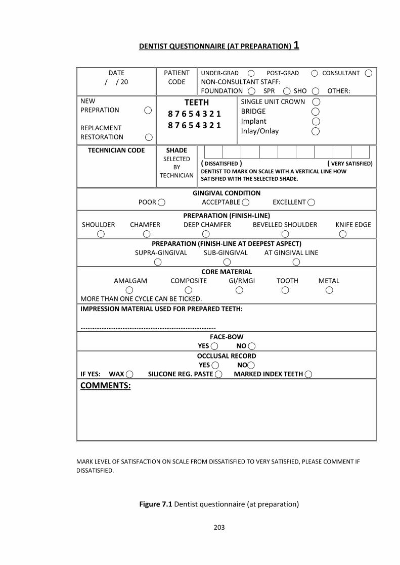
203
DENTIST QUESTIONNAIRE (AT PREPARATION) 1
MARK LEVEL OF SATISFACTION ON SCALE FROM DISSATISFIED TO VERY SATISFIED, PLEASE COMMENT IF
DISSATISFIED.
Figure 7.1 Dentist questionnaire (at preparation)
DATE / / 20
PATIENT CODE
UNDER-GRAD ⃝ POST-GRAD ⃝ CONSULTANT ⃝ NON-CONSULTANT STAFF: FOUNDATION ⃝ SPR ⃝ SHO ⃝ OTHER:
NEW PREPRATION ⃝ REPLACMENT RESTORATION ⃝
TEETH
8 7 6 5 4 3 2 1 8 7 6 5 4 3 2 1
SINGLE UNIT CROWN ⃝ BRIDGE ⃝ Implant ⃝ Inlay/Onlay ⃝
TECHNICIAN CODE SHADE SELECTED
BY TECHNICIAN
( DISSATISFIED ) ( VERY SATISFIED)
DENTIST TO MARK ON SCALE WITH A VERTICAL LINE HOW SATISFIED WITH THE SELECTED SHADE.
GINGIVAL CONDITION POOR ⃝ ACCEPTABLE ⃝ EXCELLENT ⃝
PREPARATION (FINISH-LINE) SHOULDER CHAMFER DEEP CHAMFER BEVELLED SHOULDER KNIFE EDGE ⃝ ⃝ ⃝ ⃝ ⃝
PREPARATION (FINISH-LINE AT DEEPEST ASPECT) SUPRA-GINGIVAL SUB-GINGIVAL AT GINGIVAL LINE
⃝ ⃝ ⃝
CORE MATERIAL AMALGAM COMPOSITE GI/RMGI TOOTH METAL
⃝ ⃝ ⃝ ⃝ ⃝ MORE THAN ONE CYCLE CAN BE TICKED.
IMPRESSION MATERIAL USED FOR PREPARED TEETH: …………………………………………………………………..
FACE-BOW YES ⃝ NO ⃝
OCCLUSAL RECORD YES ⃝ NO⃝
IF YES: WAX ⃝ SILICONE REG. PASTE ⃝ MARKED INDEX TEETH ⃝
COMMENTS:
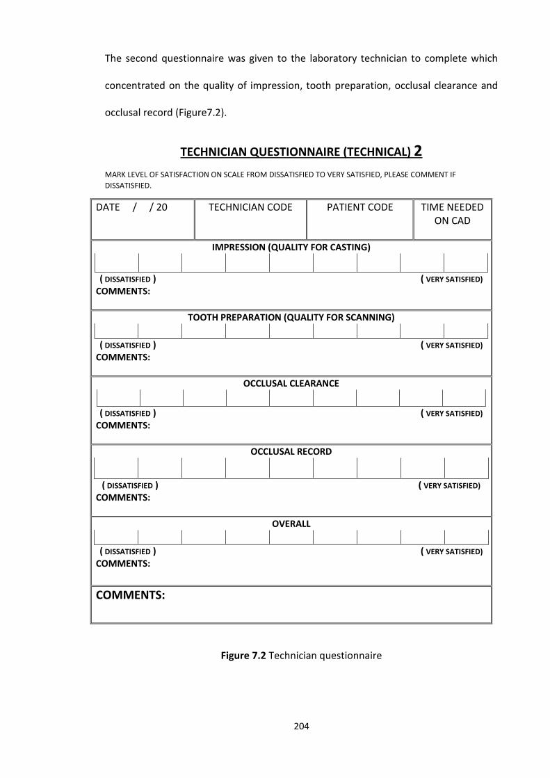
204
The second questionnaire was given to the laboratory technician to complete which
concentrated on the quality of impression, tooth preparation, occlusal clearance and
occlusal record (Figure7.2).
TECHNICIAN QUESTIONNAIRE (TECHNICAL) 2
MARK LEVEL OF SATISFACTION ON SCALE FROM DISSATISFIED TO VERY SATISFIED, PLEASE COMMENT IF
DISSATISFIED.
DATE / / 20
TECHNICIAN CODE PATIENT CODE TIME NEEDED ON CAD
IMPRESSION (QUALITY FOR CASTING)
( DISSATISFIED ) ( VERY SATISFIED) COMMENTS:
TOOTH PREPARATION (QUALITY FOR SCANNING)
( DISSATISFIED ) ( VERY SATISFIED) COMMENTS:
OCCLUSAL CLEARANCE
( DISSATISFIED ) ( VERY SATISFIED) COMMENTS:
OCCLUSAL RECORD
( DISSATISFIED ) ( VERY SATISFIED) COMMENTS:
OVERALL
( DISSATISFIED ) ( VERY SATISFIED) COMMENTS:
COMMENTS:
Figure 7.2 Technician questionnaire
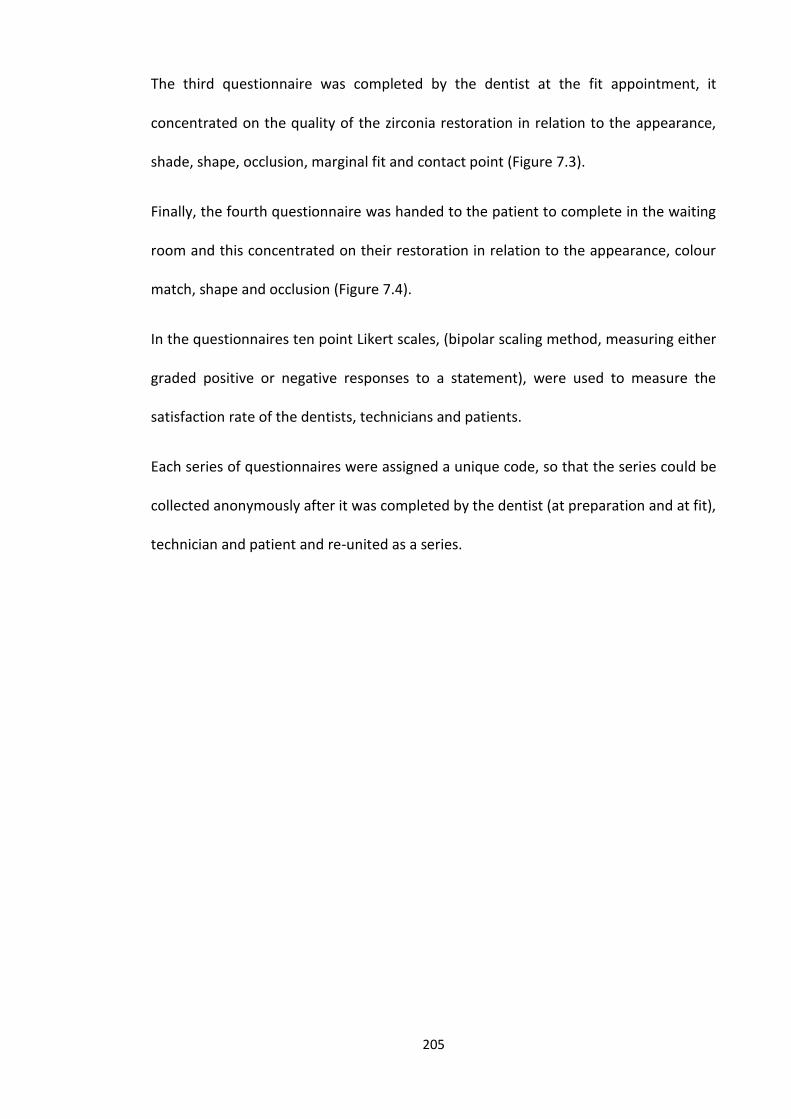
205
The third questionnaire was completed by the dentist at the fit appointment, it
concentrated on the quality of the zirconia restoration in relation to the appearance,
shade, shape, occlusion, marginal fit and contact point (Figure 7.3).
Finally, the fourth questionnaire was handed to the patient to complete in the waiting
room and this concentrated on their restoration in relation to the appearance, colour
match, shape and occlusion (Figure 7.4).
In the questionnaires ten point Likert scales, (bipolar scaling method, measuring either
graded positive or negative responses to a statement), were used to measure the
satisfaction rate of the dentists, technicians and patients.
Each series of questionnaires were assigned a unique code, so that the series could be
collected anonymously after it was completed by the dentist (at preparation and at fit),
technician and patient and re-united as a series.
206
DENTIST QUESTIONNAIRE (AT FIT) 3
MARK LEVEL OF SATISFACTION ON SCALE FROM VERY DISSATISFIED TO VERY SATISFIED, PLEASE COMMENT IF DISSATISFIED.
Figure 7.3 Dentist questionnaire (at fit)
DATE / / 20
CASE CODE
1 UNDER-GRAD ⃝ POST-GRAD ⃝ CONSULTANT ⃝ NON-CONSULTANT STAFF: FOUNDATION ⃝ SPR ⃝ SHO ⃝ OTHER:
NEW PREPRATION ⃝ REPLACMENT RESTORATION ⃝
TEETH 8 7 6 5 4 3 2 1 8 7 6 5 4 3 2 1
SINGLE UNIT CROWN ⃝ BRIDGE ⃝ Implant ⃝ Inlay/Onlay ⃝
APPEARANCE
(VERY DISSATISFIED ) ( VERY SATISFIED) COMMENTS:
SHADE MATCH
( VERY DISSATISFIED ) ( VERY SATISFIED) COMMENTS:
SHAPE AND CONTOUR
( VERY DISSATISFIED ) ( VERY SATISFIED) COMMENTS:
OCCLUSION (AT TRY-IN)
( VERY DISSATISFIED ) ( VERY SATISFIED) COMMENTS:
OCCLUSION (AFTER ADJUSTMENT AND CEMENTATION)
( VERY DISSATISFIED ) ( VERY SATISFIED) COMMENTS:
MARGINAL FIT
( VERY DISSATISFIED ) ( VERY SATISFIED) COMMENTS:
CONTACT POINT
( VERY DISSATISFIED ) ( VERY SATISFIED) COMMENTS:
OVERALL
( VERY DISSATISFIED ) ( VERY SATISFIED) COMMENTS:

207
PATIENT QUESTIONNAIRE 4
MARK LEVEL OF SATISFACTION ON SCALE FROM DISSATISFIED TO VERY SATISFIED, PLEASE COMMENT IF
DISSATISFIED.
DATE / / 20
AGE
GENDER MALE ⃝ FEMALE ⃝
PATIENT CODE
APPEARANCE
( DISSATISFIED ) ( VERY SATISFIED) COMMENTS:
COLOUR MATCH
( DISSATISFIED ) ( VERY SATISFIED)
COMMENTS:
SHAPE AND CONTOUR
( DISSATISFIED ) ( VERY SATISFIED)
COMMENTS:
BITE AND COMFORT (AFTER ADJUSTMENT AND CEMENTATION)
( DISSATISFIED ) ( VERY SATISFIED)
COMMENTS:
OVERALL
( DISSATISFIED ) ( VERY SATISFIED)
COMMENTS:
COMMENTS:
PLEASE RETURN TO RECPTION.
Figure 7.4 Patient questionnaire
208
Economical evaluation
In order to evaluate the impact of cost on manufacture of indirect restorations the cost
of gold and zirconia blocks needed for a defined number of units was calculated and
compared. A unit in terms of indirect restoration was regarded as either a crown,
inlay/onlay, bridge retainer or pontic.
As gold prices are fluctuant, this makes it difficult to determine the exact cost of dental
restoration made out of gold. By searching the prices of gold between the years 2011
and 2015, the minimum price was £20/g and the highest was £37/g
(http://goldprice.org/). In order to calculate the average cost of gold per unit of indirect
restoration, data was collected from Dundee Dental Hospital and School restorative
laboratory regarding the amount of gold (g) used to construct different indirect dental
restorations (single, two units, three units, four units, and five units) from 2010 to 2014
log books. Indirect units can be made from zirconia blocks of different dimensions and
costs. Depending on the size block used will depend on how many units can be milled
from the block. For each block size the cost per unit generated was calculated based
upon the cost of zirconia blocks in 2015. Hence the cost of each unit of indirect
restoration prepared using high fusing gold alloy and zirconia blocks could be compared.
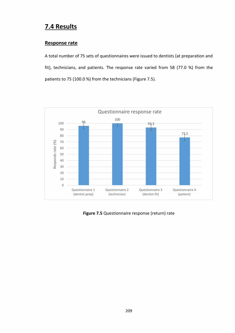
209
7.4 Results
Response rate
A total number of 75 sets of questionnaires were issued to dentists (at preparation and
fit), technicians, and patients. The response rate varied from 58 (77.0 %) from the
patients to 75 (100.0 %) from the technicians (Figure 7.5).
Figure 7.5 Questionnaire response (return) rate
96100
93.3
77.3
0
10
20
30
40
50
60
70
80
90
100
Questionnaire 1(dentist-prep)
Questionnaire 2(technician)
Questionnaire 3(dentist-fit)
Questionnaire 4(patient)
Res
po
nd
s ra
te (
%)
Questionnaire response rate
210
Questionnaire 1 (Dentist at preparation)
The dentist preparation questionnaire (72, 96.0 % returned) included mainly factual and
general questions. The responses are shown in (Figure 7.6). The responses were from
29 (40.0 %) under-graduate dental students, 7 (10.0 %) post-graduate dental students,
24 (33.0 %) consultants, 6 (8.0 %) non-consultant staff (foundation trainees) and 6 (8.0
%) speciality trainees. In total, the results from the questionnaires indicated that 127
teeth were prepared for indirect restorations, the majority of cases were new
preparations (n = 40, 55.5 %), 28 (38.8 %) were replacement restorations and finally 4
(5.7 %) were combined between new preparation and replacement restoration. The
majority of the questionnaires returned related to single crowns 56 (70.0 %), followed
by bridges 16 (20.0 %), 1 (1.2 %) implant, and finally 7 (8.8 %) inlay and onlay, some
responses had a combination of dental restorations (Figure 7.6).
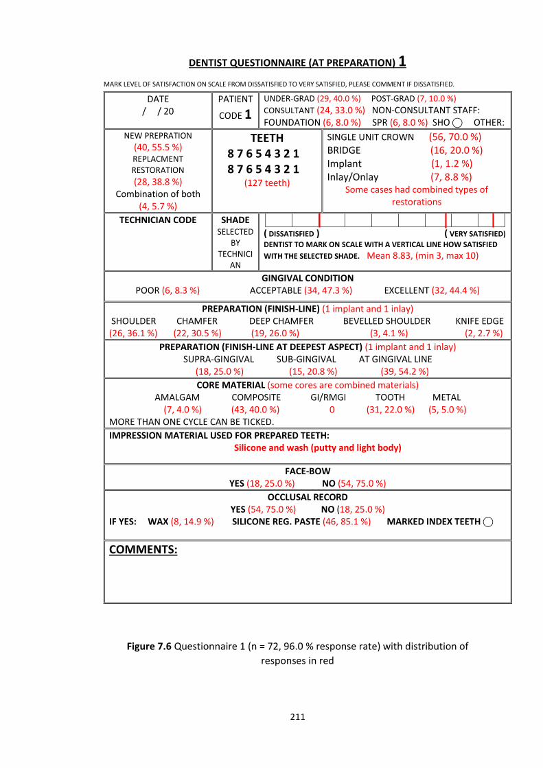
211
DENTIST QUESTIONNAIRE (AT PREPARATION) 1
MARK LEVEL OF SATISFACTION ON SCALE FROM DISSATISFIED TO VERY SATISFIED, PLEASE COMMENT IF DISSATISFIED.
Figure 7.6 Questionnaire 1 (n = 72, 96.0 % response rate) with distribution of
responses in red
DATE / / 20
PATIENT
CODE 1
UNDER-GRAD (29, 40.0 %) POST-GRAD (7, 10.0 %)
CONSULTANT (24, 33.0 %) NON-CONSULTANT STAFF: FOUNDATION (6, 8.0 %) SPR (6, 8.0 %) SHO ⃝ OTHER:
NEW PREPRATION (40, 55.5 %) REPLACMENT RESTORATION
(28, 38.8 %) Combination of both
(4, 5.7 %)
TEETH
8 7 6 5 4 3 2 1 8 7 6 5 4 3 2 1
(127 teeth)
SINGLE UNIT CROWN (56, 70.0 %) BRIDGE (16, 20.0 %) Implant (1, 1.2 %) Inlay/Onlay (7, 8.8 %)
Some cases had combined types of restorations
TECHNICIAN CODE SHADE SELECTED
BY TECHNICI
AN
( DISSATISFIED ) ( VERY SATISFIED)
DENTIST TO MARK ON SCALE WITH A VERTICAL LINE HOW SATISFIED
WITH THE SELECTED SHADE. Mean 8.83, (min 3, max 10)
GINGIVAL CONDITION POOR (6, 8.3 %) ACCEPTABLE (34, 47.3 %) EXCELLENT (32, 44.4 %)
PREPARATION (FINISH-LINE) (1 implant and 1 inlay) SHOULDER CHAMFER DEEP CHAMFER BEVELLED SHOULDER KNIFE EDGE (26, 36.1 %) (22, 30.5 %) (19, 26.0 %) (3, 4.1 %) (2, 2.7 %)
PREPARATION (FINISH-LINE AT DEEPEST ASPECT) (1 implant and 1 inlay) SUPRA-GINGIVAL SUB-GINGIVAL AT GINGIVAL LINE
(18, 25.0 %) (15, 20.8 %) (39, 54.2 %)
CORE MATERIAL (some cores are combined materials) AMALGAM COMPOSITE GI/RMGI TOOTH METAL
(7, 4.0 %) (43, 40.0 %) 0 (31, 22.0 %) (5, 5.0 %) MORE THAN ONE CYCLE CAN BE TICKED.
IMPRESSION MATERIAL USED FOR PREPARED TEETH: Silicone and wash (putty and light body)
FACE-BOW YES (18, 25.0 %) NO (54, 75.0 %)
OCCLUSAL RECORD YES (54, 75.0 %) NO (18, 25.0 %)
IF YES: WAX (8, 14.9 %) SILICONE REG. PASTE (46, 85.1 %) MARKED INDEX TEETH ⃝
COMMENTS:
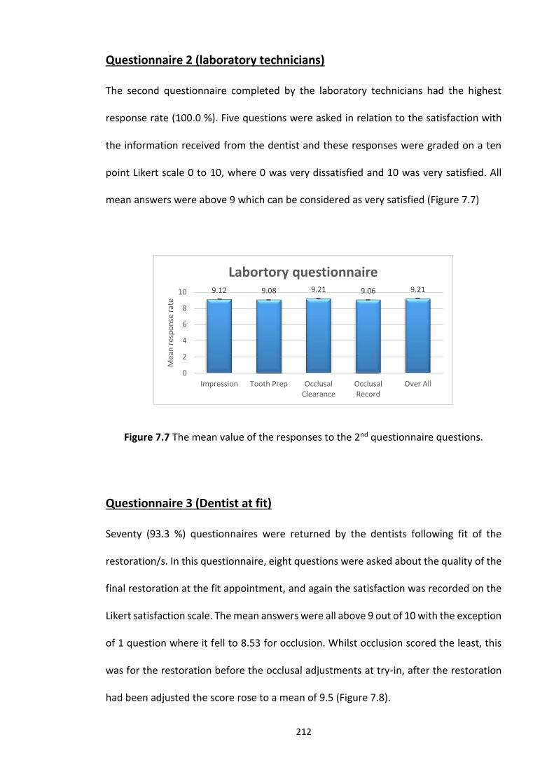
212
Questionnaire 2 (laboratory technicians)
The second questionnaire completed by the laboratory technicians had the highest
response rate (100.0 %). Five questions were asked in relation to the satisfaction with
the information received from the dentist and these responses were graded on a ten
point Likert scale 0 to 10, where 0 was very dissatisfied and 10 was very satisfied. All
mean answers were above 9 which can be considered as very satisfied (Figure 7.7)
Figure 7.7 The mean value of the responses to the 2nd questionnaire questions.
Questionnaire 3 (Dentist at fit)
Seventy (93.3 %) questionnaires were returned by the dentists following fit of the
restoration/s. In this questionnaire, eight questions were asked about the quality of the
final restoration at the fit appointment, and again the satisfaction was recorded on the
Likert satisfaction scale. The mean answers were all above 9 out of 10 with the exception
of 1 question where it fell to 8.53 for occlusion. Whilst occlusion scored the least, this
was for the restoration before the occlusal adjustments at try-in, after the restoration
had been adjusted the score rose to a mean of 9.5 (Figure 7.8).
9.12 9.08 9.21 9.06 9.21
0
2
4
6
8
10
Impression Tooth Prep OcclusalClearance
OcclusalRecord
Over All
Mea
n r
esp
on
se r
ate
Labortory questionnaire
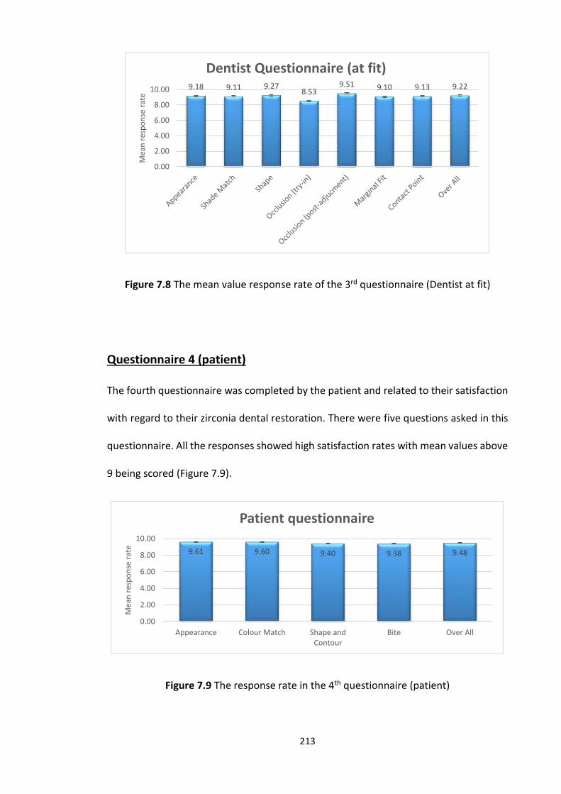
213
Figure 7.8 The mean value response rate of the 3rd questionnaire (Dentist at fit)
Questionnaire 4 (patient)
The fourth questionnaire was completed by the patient and related to their satisfaction
with regard to their zirconia dental restoration. There were five questions asked in this
questionnaire. All the responses showed high satisfaction rates with mean values above
9 being scored (Figure 7.9).
Figure 7.9 The response rate in the 4th questionnaire (patient)
9.18 9.11 9.278.53
9.51 9.10 9.13 9.22
0.00
2.00
4.00
6.00
8.00
10.00
Mea
n r
esp
on
se r
ate
Dentist Questionnaire (at fit)
9.61 9.60 9.40 9.38 9.48
0.00
2.00
4.00
6.00
8.00
10.00
Appearance Colour Match Shape andContour
Bite Over All
Mea
n r
esp
on
se r
ate
Patient questionnaire
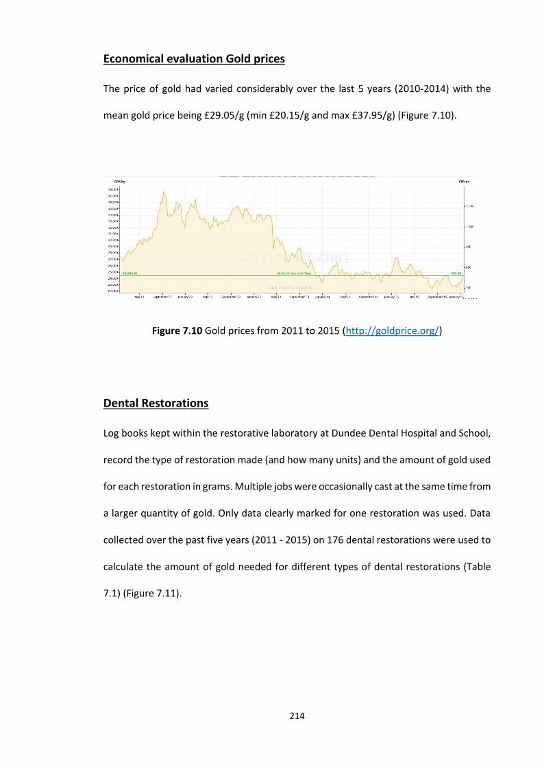
214
Economical evaluation Gold prices
The price of gold had varied considerably over the last 5 years (2010-2014) with the
mean gold price being £29.05/g (min £20.15/g and max £37.95/g) (Figure 7.10).
Figure 7.10 Gold prices from 2011 to 2015 (http://goldprice.org/)
Dental Restorations
Log books kept within the restorative laboratory at Dundee Dental Hospital and School,
record the type of restoration made (and how many units) and the amount of gold used
for each restoration in grams. Multiple jobs were occasionally cast at the same time from
a larger quantity of gold. Only data clearly marked for one restoration was used. Data
collected over the past five years (2011 - 2015) on 176 dental restorations were used to
calculate the amount of gold needed for different types of dental restorations (Table
7.1) (Figure 7.11).
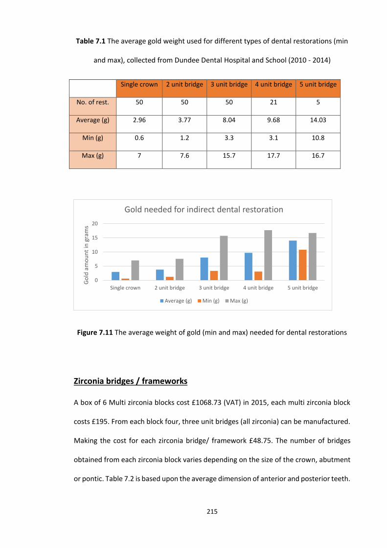
215
Table 7.1 The average gold weight used for different types of dental restorations (min
and max), collected from Dundee Dental Hospital and School (2010 - 2014)
Single crown 2 unit bridge 3 unit bridge 4 unit bridge 5 unit bridge
No. of rest. 50 50 50 21 5
Average (g) 2.96 3.77 8.04 9.68 14.03
Min (g) 0.6 1.2 3.3 3.1 10.8
Max (g) 7 7.6 15.7 17.7 16.7
Figure 7.11 The average weight of gold (min and max) needed for dental restorations
Zirconia bridges / frameworks
A box of 6 Multi zirconia blocks cost £1068.73 (VAT) in 2015, each multi zirconia block
costs £195. From each block four, three unit bridges (all zirconia) can be manufactured.
Making the cost for each zirconia bridge/ framework £48.75. The number of bridges
obtained from each zirconia block varies depending on the size of the crown, abutment
or pontic. Table 7.2 is based upon the average dimension of anterior and posterior teeth.
0
5
10
15
20
Single crown 2 unit bridge 3 unit bridge 4 unit bridge 5 unit bridge
Go
ld a
mo
un
t in
gra
ms
Gold needed for indirect dental restoration
Average (g) Min (g) Max (g)
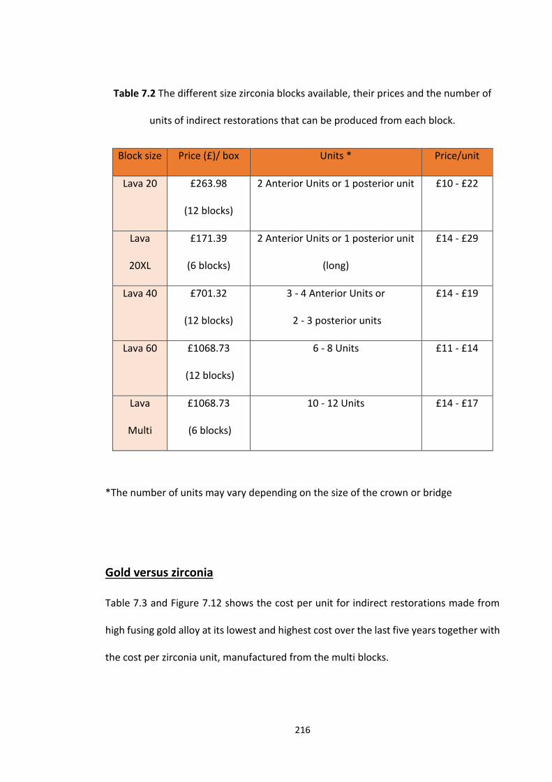
216
Table 7.2 The different size zirconia blocks available, their prices and the number of
units of indirect restorations that can be produced from each block.
Block size Price (£)/ box Units * Price/unit
Lava 20 £263.98
(12 blocks)
2 Anterior Units or 1 posterior unit £10 - £22
Lava
20XL
£171.39
(6 blocks)
2 Anterior Units or 1 posterior unit
(long)
£14 - £29
Lava 40 £701.32
(12 blocks)
3 - 4 Anterior Units or
2 - 3 posterior units
£14 - £19
Lava 60 £1068.73
(12 blocks)
6 - 8 Units £11 - £14
Lava
Multi
£1068.73
(6 blocks)
10 - 12 Units £14 - £17
*The number of units may vary depending on the size of the crown or bridge
Gold versus zirconia
Table 7.3 and Figure 7.12 shows the cost per unit for indirect restorations made from
high fusing gold alloy at its lowest and highest cost over the last five years together with
the cost per zirconia unit, manufactured from the multi blocks.

217
Table 7.3 The prices of dental restorations made from gold and zirconia
1 Unit 2 Units 3 Units 4 Units 5 Units
Gold at £20 £59.20 £75.40 £160 £193.60 £280.60
Gold at £37 £109.52 £139.49 £297.48 £358.16 £519.11
Zirconia £21.99 £29.22 £44.53 £89.06 £89.06
Figure 7.12 A comparison of gold prices versus zirconia for different dental
restorations
For the most commonly provided restoration, a single unit crown, gold (at its cheapest)
is 2.7 times more expensive than a zirconia restoration and, at its most expensive over
the last 5 years, it is 5 times more expensive. When longer span bridges are concerned,
for example the three unit conventional bridge, the differences in cost are 3.6 times and
6.7 times more expensive for gold based restorations (at its cheapest and most
expensive respectively) compared to zirconia.
£0.00
£200.00
£400.00
£600.00
1 Unit 2 Units 3 Units 4 Units 5 Units
Pri
ces
in G
BP
(£
)
Compare the prices of dental restorations (gold and zirconia)
Gold at £20 Gold at £37 Zirconia
218
7.5 Discussion
Due to the lack of literature on dentist, dental technician and patient satisfaction with
CAD CAM restorations, four questionnaires were designed to capture information on
different aspects of different stages in the process of providing such a restoration. Two
of the questionnaires were designed for the dentist, one to be filled in at tooth
preparation and one at fit, one questionnaire was for the dental technician and one for
the patient. The questionnaires were first piloted on the targeted population (dentists
and dental technicians) to check for clarity and to ensure that all the aspects relevant to
the preparation, fabrication and cementation of CAD CAM restorations were included.
According to Dillman, the response rate of questionnaires is calculated as follows:
Response rate = No. of questionnaire returned X 100/ No. of all questionnaires issued
(Dillman et al., 1984). In this survey 75 sets of questionnaires were issued, the overall
response rate was generally good for dentists (n = 72 first questionnaire (96.0 %) and n
= 70 second questionnaire (93.3 %)) and technicians (n = 75 (100.0 %)), however whilst
the response rate was worse for patients (n = 58 (77.0 %)) it is still regarded as good and
acceptable. The good response rate, of the dentist and technician questionnaire, is
probably a result of having a “captive target population” within the Dental School with
a vested interest in CAD CAM. However, the lower response rate of the patients, may
be due to many factors such as, the dentist did not hand the questionnaire to the
patients, time related issues for the dentist and patient or the patient simply was not
interested in participating in the survey and filling in the questionnaire.

219
In relation to the first questionnaire the majority of the operators carrying out the tooth
preparations were undergraduate students (n = 29 (40.0 %)) and consultants (n = 24
(33.0 %)) with smaller numbers of postgraduate students (n = 7 (10.0 %)), foundation
trainees (n = 6 (8.0 %)) and StRs (n = 6 (8.0 %)). This distribution is entirely expected
because the survey was carried out in a teaching hospital.
In relation to the type of preparation, new preparations were the most common (n = 40
(55.5 %)) compared with replacement restorations only (n = 28 (38.8 %)) and a
combination of both (n = 4 (5.7 %). A chamfer finish-line is the recommended
preparation margin for all ceramic restorations (Chadwick and Hall, 2011) and was the
most commonly prepared margin (chamfer (n = 22 (30.5 %)), deep chamfer (n = 19 (26.0
%)). Closer examination of the questionnaires revealed that the majority of chamfer
finish lines were obtained for the new preparations demonstrating that the operators
were conforming to the taught standard or at least responding to the questionnaire with
an answer which conforms to the taught standard. With hindsight, it would have been
good to include the same question about margin configuration in the technician’s
questionnaire for comparison and validation. This having been said, the technician’s
satisfaction with the tooth preparations was high. The preparation of a shoulder finish-
line was lower (n = 26 (36.1 %)), and this is due to the “inherited” finish lines in relation
to the replacement restoration cases which would have mainly been metal ceramic
crowns originally. It is difficult if not impossible to modify the old preparation and
change it from a shoulder which was used for the metal ceramic restoration to a chamfer
for the CAD CAM zirconia restorations.
220
Most of the prepared teeth were anterior, as CAD CAM restorations were chosen
because they can produce highly aesthetic outcomes. In relation to aesthetics it is also
important that the finish-line is equi-gingival, so that unsightly margins and root surfaces
are not visible (Nugala et al., 2012). In this survey 39 (54.1 %) of the restorations had
margins that were equi-gingival making them aesthetic and easy to clean (Khuller and
Sharma, 2009). Lip or smile line is also important to take into consideration and this may
explain why 18 (25.0 %) of margins were left supragingivally in cases where aesthetics
cervically was less important in patients with a low smile line. This aspect could not be
investigated through these questionnaires but since patient satisfaction with aesthetics
was extremely high it is assumed that these supragingival margins were all acceptable.
When it came to the core material, composite was the most commonly used (n = 43,
(40.0 %)), this can be explained by two points. Firstly, that composite was used as a filling
material in that tooth and it acted as a restoration for some time, due to its high
mechanical and aesthetic properties, making it the material of choice for restoring teeth
(Cramer et al., 2011). Secondly, during the treatment planning phase a decision to
restore the tooth with an all ceramic crown, would have dictated a tooth coloured
material to prevent shine through of metal through the ceramic, hence composite being
the ideal choice (Monticelli et al., 2005).
When the impression of the prepared teeth was carried out, almost all the participants
used silicone impression (putty and light body). This is mainly because of the accuracy
and stability of the silicone dental material. Digital imprisoning although it is becoming
the impression of choice for some practitioners due to its specification and ease of use
(Christensen, 2008), and was available for use at the Dental School, it was not used in
any of the cases. This is because students were not trained to use the Lava COS. However
221
the Consultant staff were all trained, but despite the fact that they accounted for 33.0
% of the restorations made in this survey, not one used the Lava COS scanner. The only
explanations for the staff not using the intraoral scanner is the long time between the
training and the patient’s appointment the fact that the staff were trained at the under
graduate level with conventional impressions making them more comfortable with this
technique and finding it easier to use. Perhaps repeated continual training in the use of
the scanner on phantom heads may raise the confidence levels with this new technique
and hence the frequency of use.
The laboratory technician’s questionnaire had the highest response rate (100.0 %), with
high satisfaction rates (> 9 out of 10) for all questions asked. The high response rate is
due to the fact that the technicians were central to the distribution of questionnaires in
the laboratory. The high satisfaction rates for the technicians reflects the high quality of
the clinical work carried out, because the dental technicians are essentially assessing the
work carried out by the clinicians (the impression, tooth preparation, occlusal clearance
and occlusal record (if provided)).
At the fit appointment, a questionnaire was completed in by the dentist in order to
assess the restoration and evaluate the laboratory work carried out. The questionnaire
covered different aspects, appearance, shade match, shape, occlusion (try-in), occlusion
(post-adjustment), marginal fit and contact point. The results indicated high satisfaction
rates (above 9 out of 10) in relation to all aspects of the restoration, with the exception
of the occlusion (try-in) which scored 8.53 out of 10. Usually minor adjustments are
required with most indirect dental restorations at the try-in stage (Wassell et al., 2002a),
and CAD CAM restorations are no exception. Most of the restorations made would have
been constructed using a zirconia coping or frame work veneered with ceramic,
222
therefore the occlusal scheme is down to human judgment and may account for the
satisfaction with the occlusion. This having been said, the satisfaction score of 8.53 may
still considered high and the amount of adjustment required probably minimal. After
the occlusal adjustment the satisfaction with the final occlusion, as assessed by the
patient, rose to 9.51 out of 10.
The patient’s questionnaire asked five questions relating to the appearance, colour
match, shape and contour and bite; for all parameters the satisfaction rate was over 9.
Previous patient satisfaction questionnaires have focused on the dental clinic, and
dental team skills (Burke and Croucher, 1996, Newsome and Wright, 1999). More
commonly, patient satisfaction rates have been investigated in retrospective studies,
when the survival rate is investigated (Kan et al., 2003, Gotfredsen, 2004, Meijndert et
al., 2007, De Rouck et al., 2008, Tartaglia et al., 2011, Shi et al., 2015). This is because
patient satisfaction is also based upon restoration survival and longevity. Unfortunately
the restorations in this audit cannot be followed up for longevity and traced back to the
outcomes of the four questionnaires, as for an audit and Caldicott Guardian approval,
all questionnaires have to be anonymised but this could be an interesting part of any
further research.
Economical (cost) analysis is discussed widely but less commonly so among dental
professionals or organisations (Walton and Layton, 2012). It is clear that discussing
treatments and costs with patients is of a great importance, because patients might
change their treatment options due to the cost. Therefore evidence of cost effectiveness
of restorations important to inform dentist patient discussion on treatment options. In
2004 Kelly and Smales investigated the long-term (15 years) cost effectiveness of using
direct restorations for restoring large tooth defects or indirect dental restoration (all
223
metal or metal ceramic crowns) in private dental practices. They concluded that direct
restorations were the most cost effective, followed by all metal and finally metal ceramic
indirect restorations (Kelly and Smales, 2004). The results of this study were not
surprising, as indirect restorations require more steps and materials which can be
expensive. These results were based on the dentists’ evaluation, but on the other hand,
cost satisfaction analysis (at treatment and at follow up) of fixed prosthodontic
restoration has been investigated among patients who have received this type of dental
restorations within the previous 20 years by sending a questionnaire (VAS) to the
patients. The results showed that, although the patients considered fixed dental
prostheses to be expensive at the time of treatment, in the long run, they felt that they
were good value (Walton and Layton, 2012). Such restorations may therefore be cost
effective in the long term.
In this audit, the difference between the materials (gold and zirconia) used to produce
indirect dental restorations were compared, mainly because gold has been the material
of choice for many years, due to its superior specifications (Liviu Steier et al., 2007) and
because high fusing gold alloy is the material of choice for metal ceramic restorations at
Dundee Dental School. By monitoring the prices of gold in the last 5 years, it is clear that
the prices fluctuate quite dramatically (min £20.15/g and max £37.95/g), this makes it
difficult to predict the exact cost of an indirect dental restoration at any given time. This
is also compounded by the size of any restoration. On the other hand zirconia blocks
generally have a set price (although might be subjected to some price increase), making
estimation of cost of zirconia based indirect dental restorations more predictable.
Using CAD CAM technology is more time and cost effective compared with conventional
practice, as it can produce dental restorations in less time and less man hours (Lee and
224
Gallucci, 2013). Zirconia is also cheaper compared with gold restorations as can be seen
from the results of this audit (where the material cost of gold based restorations could
reach nearly five to six times that of a CAD CAM zirconia based restoration) and the
study by Joda and Bragger (2015), where the cost of CAD CAM implant restorations are
compared with conventional implant prostheses. The results showed that the cost of
the digital workflow was significantly lower than that of the conventional workflow,
regardless of the price of the implant (Joda and Bragger, 2015).
It is ironic therefore that in private practice CAD CAM restorations cost more than gold
based restorations. This is probably due to the high start-up cost for the technicians in
buying the scanners and in particular the milling machines but could be overcome by a
number of laboratories/technicians having a centralized milling center. The return rates
for the questionnaires in this audit were generally good and satisfaction rates high from
all participants, but the results may have been very different if the same audit was
carried out in a busy private practice where time is inextricably linked to cost (unlike in
a teaching hospital) and perhaps greater patient expectations when paying large bills.
7.6 Conclusions
Within the limitation of this audit and results, the followings can be concluded:
1. Dentists and dental students are familiar with the preparation of zirconia based
restorations.
2. The tooth preparations, impressions and laboratory work were of a high standard at
Dundee Dental Hospital.
225
3. The patients were highly satisfied with the final outcome of the zirconia based dental
restoration.
4. Zirconia based restorations were more cost effective in the short term.
226
Chapter 8
Conclusion and further work
227
8.1 Principal Findings and further work
The principal findings of this PhD thesis are:
1. Lava COS and Lava CAD CAM system (Lava™, 3M, ESPE), produces highly precise and
highly aesthetic indirect zirconia based restorations.
2. Dentists apply different forces during cementation of indirect dental restorations, the
highest force being applied in the first 30 seconds, then dropping to a lower consistent
force with time. Despite the differences in force applied there was no impact on
accuracy of fit.
3. Additional firing cycles used with veneering ceramics onto zirconia frameworks can
lead to a significant increase in internal and marginal gaps (fit).
4. Increasing the span length of all zirconia bridges is unlikely to have an impact on the
internal and marginal fit of the all zirconia bridges.
5. Zirconia based restorations (all zirconia, veneered zirconia frameworks and un-
veneered zirconia frameworks) can withstand forces in excess of occlusal forces
normally achieved by patients in both the anterior and posterior regions of the mouth.
Whilst veneering a zirconia framework increases the strength of the frameworks, the all
zirconia restorations were the strongest.
6. The audit showed that, at Dundee Dental Hospital and School both dentists and dental
students are familiar with zirconia based restoration tooth preparation, this was
followed by a high standard and quality of the impression and laboratory work resulting
in dentists and patients being highly satisfied with the final zirconia based indirect dental
restoration provided. The cost analysis showed that zirconia based restorations are five
228
to six times cheaper than gold alloy based restorations, but we need to have in
consideration the set-up cost of the CAD CAM system.
8.2 Further work
Further work could be carried out to:
- investigate the seating pressure applied to different types of CAD CAM restorations
(different span bridges with differing configuration (curved arch or straight span),
veneers, inlays and onlays) using different types of luting cements with different
viscosities, and the impact that would have on fit.
- investigate the effect of veneering and firing cycles on the fit of zirconia based
restorations with full firing cycles (e.g. sintering, de-waxing, ceramic pressing, glazing
and finishing).
- investigate the effect of different types of veneering ceramics and different veneering
techniques (e.g. pressing, conventional, CAD on) on the fit and strength.
- investigate the strength of zirconia based restorations using different span lengths,
different configurations and different connector diameters and different thickness of
zirconia based restorations.
- investigate the accuracy of different types of conventional impression materials and
techniques can be compared with different types of digital impression systems.
- repeat the audit but with a tracking code, to allow investigation of the survival and
longevity of the restoration and to compare this with the satisfaction of the patient and
dentist in the long term.
229
References
ABDUO, J., LYONS, K. & SWAIN, M. 2010. Fit of zirconia fixed partial denture: a systematic review. Journal Oral Rehabilitation, 37, 866-76.
ABOUSHELIB, M. N., DE KLER, M., VAN DER ZEL, J. M. & FEILZER, A. J. 2008. Effect of veneering method on the fracture and bond strength of bilayered zirconia restorations. International Journal of Prosthodontics, 21, 237-40.
ADABO, G. L., ZANAROTTI, E., FONSECA, R. G. & CRUZ, C. A. D. S. 1999. Effect of disinfectant agents on dimensional stability of elastomeric impression materials. The Journal of Prosthetic Dentistry, 81, 621-624.
ADAIR, P. J. & GROSSMAN, D. G. 1984. The castable ceramic crown. International Journal of Periodontics Restorative Dentistry, 4, 32-46.
AGUSTÍN-PANADERO, R., ROMÁN-RODRÍGUEZ, J. L., FERREIROA, A., SOLÁ-RUÍZ, M. F. & FONS-FONT, A. 2014. Zirconia in fixed prosthesis. A literature review. Journal of Clinical and Experimental Dentistry, 6, e66-e73.
AHLGREN, C., AHNLIDE, I., BJÖRKNER, B., BRUZE, M., LIEDHOLM, R., MÖLLER, H. & NILNER, K. 2002. Contact allergy to gold is correlated to dental gold. Acta Dermato-Venereologica, 82, 41-44.
AHLGREN, C., AXÉLL, T., MÖLLER, H., ISAKSSON, M., LIEDHOLM, R. & BRUZE, M. 2014. Contact allergies to potential allergens in patients with oral lichen lesions. Clinical Oral Investigations, 18, 227-237.
AHRBERG, D., LAUER, H. C., AHRBERG, M. & WEIGL, P. 2015. Evaluation of fit and efficiency of CAD/CAM fabricated all-ceramic restorations based on direct and indirect digitalization: a double-blinded, randomized clinical trial. Clinical Oral Investigations.
AKARSLAN, Z. Z. & YILDIRIM BICER, A. Z. 2013. Influence of gag reflex on dental attendance, dental anxiety, self-reported temporomandibular disorders and prosthetic restorations. Journal of Oral Rehabilitation, 40, 932-9.
ALGHAZZAWI, T. F., LEMONS, J., LIU, P. R., ESSIG, M. E. & JANOWSKI, G. M. 2012. Evaluation of the optical properties of CAD-CAM generated yttria-stabilized zirconia and glass-ceramic laminate veneers. Journal of Prosthetic Dentistry, 107, 300-8.
ALKAN, A., KESKINER, I., ARICI, S. & SATO, S. 2006. The effect of periodontitis on biting abilities. Journal of Periodontology, 77, 1442-1445.
ALMEIDA E SILVA, J. S., ERDELT, K., EDELHOFF, D., ARAUJO, E., STIMMELMAYR, M., VIEIRA, L. C. & GUTH, J. F. 2014. Marginal and internal fit of four-unit zirconia fixed dental prostheses based on digital and conventional impression techniques. Clinical Oral Investigations
18, 515-23. ALMORTADI, N. & CHADWICK, R. G. 2010. Disinfection of dental impressions - compliance to
accepted standards. British Dental Journal, 209, 607-11. ANNERSTEDT, A., ENGSTROM, U., HANSSON, A., JANSSON, T., KARLSSON, S., LILJHAGEN, H.,
LINDQUIST, E., RYDHAMMAR, E., TYREMAN-BANDHEDE, M., SVENSSON, P. & WANDEL, U. 1996. Axial wall convergence of full veneer crown preparations. Documented for dental students and general practitioners. Acta Odontol Scand, 54, 109-12.
ANUNMANA, C., CHAROENCHITT, M. & ASVANUND, C. 2014. Gap comparison between single crown and three-unit bridge zirconia substructures. The Journal of Advanced Prosthodontics, 6, 253-258.
ANUSAVICE, K. J., SHEN, C. & RAWLS, H. R. 2012. Phillips' Science of Dental Materials, 12e (Anusavice Phillip's Science of Dental Materials).
APHOLT, W., BINDL, A., LUTHY, H. & MORMANN, W. H. 2001. Flexural strength of Cerec 2 machined and jointed InCeram-Alumina and InCeram-Zirconia bars. Dental Materials, 17, 260-7.
230
ARTHUR, R. 1855. A NEW METHOD OF USING GOLD FOIL. American Journal of Dental Science 600-605.
ARTHUR, R. 1977. A new method of using gold foil. Bulletin of the History of Denttistry, 25, 46-50.
ATT, W., KOMINE, F., GERDS, T. & STRUB, J. R. 2009. Marginal adaptation of three different zirconium dioxide three-unit fixed dental prostheses. Journal of Prosthetic Dentistry, 101, 239-247.
ATTARD, N. J., ZARB, G. A. & LAPORTE, A. 2005. Long-term treatment costs associated with implant-supported mandibular prostheses in edentulous patients. International Journal of Prosthodontics, 18, 117-23.
BAIG, M. R., TAN, K. B. & NICHOLLS, J. I. 2010. Evaluation of the marginal fit of a zirconia ceramic computer-aided machined (CAM) crown system. Journal of Prosthetic Dentistry, 104, 216-27.
BAKKE, M. 2006. Bite Force and Occlusion. Seminars in Orthodontics, 12, 120-126. BAKKE, M., HOLM, B., JENSEN, B. L., MICHLER, L. & MÖLLER, E. 1990. Unilateral, isometric bite
force in 8-68-year-old women and men related to occlusal factors. Scandinavian Journal of Dental Research, 98, 149-158.
BAROUDI, K. & IBRAHEEM, S. N. 2015. Assessment of Chair-side Computer-Aided Design and Computer-Aided Manufacturing Restorations: A Review of the Literature. Journal of International Oral Health, 7, 96-104.
BATES, J. F., STAFFORD, G. D. & HARRISON, A. 1975. Masticatory function: a review of the literature. (II) Speed of movement of the mandible, rate of chewing and forces developed in chewing. Journal of Oral Rehabilitation, 2, 349-361.
BEGUMA, Z. & CHHEDAT, P. 2014. Rapid prototyping--when virtual meets reality. International Journal of Computerized Dentistry, 17, 297-306.
BEHR, M., ROSENTRITT, M., LOHER, H., KOLBECK, C., TREMPLER, C., STEMPLINGER, B., KOPZON, V. & HANDEL, G. 2008. Changes of cement properties caused by mixing errors: the therapeutic range of different cement types. Dental Materials Journal
24, 1187-93. BENSEL, T., POLLAK, R., STIMMELMAYR, M. & HEY, J. 2013. Disinfection effect of dental
impression tray adhesives. The journal Clinical Oral Investigations, 17, 497-502. BESSING, C. 1988. Alternatives to high noble dental casting gold alloys type 3. An in vitro in
vivo study. Swedish Dental Journal. Supplement, 53, 1-56. BEUER, F., AGGSTALLER, H., EDELHOFF, D. & GERNET, W. 2008a. Effect of preparation design
on the fracture resistance of zirconia crown copings. Dental Materials Journal, 27, 362-367.
BEUER, F., AGGSTALLER, H., EDELHOFF, D., GERNET, W. & SORENSEN, J. 2009a. Marginal and internal fits of fixed dental prostheses zirconia retainers. Dental Materials Journal, 25, 94-102.
BEUER, F., AGGSTALLER, H., RICHTER, J., EDELHOFF, D. & GERNET, W. 2009b. Influence of preparation angle on marginal and internal fit of CAD/CAM-fabricated zirconia crown copings. Quintessence International (Berlin, Germany : 1985), 40, 243-250.
BEUER, F., EDELHOFF, D., GERNET, W. & NAUMANN, M. 2008b. Effect of preparation angles on the precision of zirconia crown copings fabricated by CAD/CAM system. Dental Materials Journal, 27, 814-820.
BEUER, F., EDELHOFF, D., GERNET, W. & SORENSEN, J. A. 2009c. Three-year clinical prospective evaluation of zirconia-based posterior fixed dental prostheses (FDPs). Journal Clinical Oral Investigations, 13, 445-51.
BEUER, F., NAUMANN, M., GERNET, W. & SORENSEN, J. A. 2009d. Precision of fit: Zirconia three-unit fixed dental prostheses. Journal Clinical Oral Investigations, 13, 343-349.
BEUER, F., NEUMEIER, P. & NAUMANN, M. 2009e. Marginal fit of 14-unit zirconia fixed dental prosthesis retainers. Journal of Oral Rehabilitation, 36, 142-149.
231
BEUER, F., SCHWEIGER, J. & EDELHOFF, D. 2008c. Digital dentistry: an overview of recent developments for CAD/CAM generated restorations. British Dental Journal, 204, 505-511.
BEUER, F., SCHWEIGER, J., EICHBERGER, M., KAPPERT, H. F., GERNET, W. & EDELHOFF, D. 2009f. High-strength CAD/CAM-fabricated veneering material sintered to zirconia copings--a new fabrication mode for all-ceramic restorations. Dental Materials Journal, 25, 121-8.
BEUER, F., STIMMELMAYR, M., GERNET, W., EDELHOFF, D., GUH, J. F. & NAUMANN, M. 2010. Prospective study of zirconia-based restorations: 3-year clinical results. Quintessence International, 41, 631-7.
BHOWMIK, H. & PARKHEDKAR, R. 2011. A comparison of marginal fit of glass infiltrated alumina copings fabricated using two different techniques and the effect of firing cycles over them. The Journal of Advanced Prosthodontics, 3, 196-203.
BINDL, A. & MORMANN, W. H. 2005. Marginal and internal fit of all-ceramic CAD/CAM crown-copings on chamfer preparations. Journal of Oral Rehabilitation, 32, 441-7.
BINDL, A. & MORMANN, W. H. 2007. Fit of all-ceramic posterior fixed partial denture frameworks in vitro. International Journal of Periodontics Restorative Dentistry, 27, 567-75.
BINDRA, B. & HEATH, J. R. 1997. Adhesion of elastomeric impression materials to trays. Journal of Oral Rehabilitation, 24, 63-9.
BLACK, G. V. 1917. A work on operavtive dentistry Medico-Dental Publishing company. BLACK, S. & AMOORE, J. N. 1993. Measurement of forces applied during the clinical
cementation of dental crowns. Physiological Measurement, 14, 387-392. BLAIR, F. M., WASSELL, R. W. & STEELE, J. G. 2002. Crowns and other extra-coronal
restorations:Preparations for full veneer crowns. British Dental Journal, 192, 561-571. BONAKDARCHIAN, M., ASKARI, N. & ASKARI, M. 2009. Effect of face form on maximal molar
bite force with natural dentition. Archives of Oral Biology, 54, 201-204. BONSOR, S. J. & PEARSON, G., J. 2013. A Clinical Guide to Applied Dental Materials. BOUCHARD, P., RENOUARD, F., BOURGEOIS, D., FROMENTIN, O., JEANNERET, M. H. &
BERESNIAK, A. 2009. Cost-effectiveness modeling of dental implant vs. bridge. Clinical Oral Implants Research, 20, 583-7.
BOWER, E. J., NEWTON, P. D., GIBBONS, D. E. & NEWTON, J. T. 2004. A national survey of dental technicians: career development, professional status and job satisfaction. British Dental Journal, 197, 144-148.
BRAGGER, U., KRENANDER, P. & LANG, N. P. 2005. Economic aspects of single-tooth replacement. Clinical Oral Implants Research, 16, 335-41.
BRANDAU, H. E., YAMAN, P. & MOLVAR, M. 1988. Effect of restorative procedures for a porcelain jacket crown on gingival health and height. American Journal of Dentistry, 1, 119-22.
BROSKY, M. E., PESUN, I. J., LOWDER, P. D., DELONG, R. & HODGES, J. S. 2002. Laser digitization of casts to determine the effect of tray selection and cast formation technique on accuracy. Journal of Prosthetic Dentistry, 87, 204-9.
BRULLMANN, D. & SCHULZE, R. K. 2015. Spatial resolution in CBCT machines for dental/maxillofacial applications-what do we know today? Dentomaxillofac Radiol, 44, 20140204.
BUONOCORE, M. G. 1955. A simple method of increasing the adhesion of acrylic filling materials to enamel surfaces. Journal of Dental Research, 34, 849-53.
BURKE, F. J. 1995. The effect of variations in bonding procedure on fracture resistance of dentin-bonded all-ceramic crowns. Quintessence Int, 26, 293-300.
BURKE, F. J., CRISP, R. J., COWAN, A. J., LAMB, J., THOMPSON, O. & TULLOCH, N. 2013. Five-year clinical evaluation of zirconia-based bridges in patients in UK general dental practices. J Dent, 41, 992-9.
232
BURKE, F. J. T. 1996. Fracture resistance of teeth restored with dentin-bonded crowns: The effect of increased tooth preparation. Quintessence International, 27, 115-121.
BURKE, F. J. T. 2007. Four year performance of dentine-bonded all-ceramic crowns. British Dental Journal, 202, 269-273.
BURKE, L. & CROUCHER, R. 1996. Criteria of good dental practice generated by general dental practitioners and patients. International Dental Journal, 46, 3-9.
BYRNE, G. 1992. Influence of finish-line form on crown cementation. The International Journal of Prosthodontics, 5, 137-144.
C. Â. M. VOLPATO, M. C. FREDEL, A. G. PHILIPPI & PETTER, C. O. 2010. Ceramic Material, Sciyo. CEYHAN, J. A., JOHNSON, G. H. & LEPE, X. 2003. The effect of tray selection, viscosity of
impression material, and sequence of pour on the accuracy of dies made from dual-arch impressions. Journal of Prosthetic Dentistry, 90, 143-9.
CHAAR, M. S., PASSIA, N. & KERN, M. 2015. Ten-year clinical outcome of three-unit posterior FDPs made from a glass-infiltrated zirconia reinforced alumina ceramic (In-Ceram Zirconia). Journal of Dentistry, 43, 512-7.
CHADWICK, G. & HALL, A. 2011. Chapter 11 - All-ceramic crowns. In: RICKETTS. D.N.J & BARTLETT. D (eds.) Advanced Operative Dentistry. Edinburgh: Churchill Livingstone.
CHADWICK, R. G. 1988. The durability of restorative materials PhD, University of Newcastle upon Tyne.
CHADWICK, R. G. 1989. A review: The assessment of the durability of composite resin restorative materials in vivo. Clinical Materials, 4, 241-253.
CHAN, D. C., FRAZIER, K. B., TSE, L. A. & ROSEN, D. W. 2004a. Application of rapid prototyping to operative dentistry curriculum. Journal of Dental Education, 68, 64-70.
CHAN, D. C. N., WILSON JR, A. H., BARBE, P., CRONIN JR, R. J., CHUNG, C. & CHUNG, K. 2004b. Effect of preparation convergence on retention and seating discrepancy of complete veneer crowns. Journal of Oral Rehabilitation, 31, 1007-1013.
CHEN, H. Y., HICKEL, R., SETCOS, J. C. & KUNZELMANN, K. H. 1999. Effects of surface finish and fatigue testing on the fracture strength of CAD-CAM and pressed-ceramic crowns. Journal of Prosthetic Dentistry, 82, 468-75.
CHEN, S. Y., LIANG, W. M. & CHEN, F. N. 2004. Factors affecting the accuracy of elastometric impression materials. Journal of Dentistry, 32, 603-9.
CHENG, R., YANG, H., SHAO, M. Y., HU, T. & ZHOU, X. D. 2009. Dental erosion and severe tooth decay related to soft drinks: a case report and literature review. Journal of Zheijang University SCIENCE, 10, 395-9.
CHEUNG, G. S., LAI, S. C. & NG, R. P. 2005. Fate of vital pulps beneath a metal-ceramic crown or a bridge retainer. International Endodontic Journal, 38, 521-30.
CHIEFFI, N., CHERSONI, S., PAPACCHINI, F., VANO, M., GORACCI, C., DAVIDSON, C. L., TAY, F. R. & FERRARI, M. 2007. The effect of application sustained seating pressure on adhesive luting procedure. Dental Materials, 23, 159-164.
CHO, S. H., NAGY, W. W., GOODMAN, J. T., SOLOMON, E. & KOIKE, M. 2012. The effect of multiple firings on the marginal integrity of pressable ceramic single crowns. Journal of Prosthetic Dentistry
107, 17-23. CHONG, K. H., CHAI, J., TAKAHASHI, Y. & WOZNIAK, W. 2002. Flexural strength of In-Ceram
alumina and In-Ceram zirconia core materials. International Journal of Prosthodontics, 15, 183-8.
CHRISTEL, P., MEUNIER, A., DORLOT, J. M., CROLET, J. M., WITVOET, J., SEDEL, L. & BOUTIN, P. 1988. Biomechanical Compatibility and Design of Ceramic Implants for Orthopedic Surgery. Annals of the New York Academy of Sciences, 523, 234-256.
CHRISTENSEN, G. J. 1997. What category of impression material is best for your practice? The Journal of the American Dental Association, 128, 1026-8.
CHRISTENSEN, G. J. 2005. How to kill a tooth. The Journal of the American Dental Association, 136, 1711-1713.
233
CHRISTENSEN, G. J. 2008. Will digital impressions eliminate the current problems with conventional impressions? Journal of the American Dental Association, 139, 761-3.
CHRISTENSEN, G. J. 2009. Impressions Are Changing: Deciding on Conventional, Digital or Digital Plus In-Office Milling. Journal of the American Dental Association, 140, 1301-1304.
COHEN, A., LAVIV, A., BERMAN, P., NASHEF, R. & ABU-TAIR, J. 2009. Mandibular reconstruction using stereolithographic 3-dimensional printing modeling technology. Oral Surg Oral Med Oral Pathol Oral Radiol Endod, 108, 661-6.
COMBE, E. C., BURKE, F. J. T. & DOUGLAS, W. H. 1999. Dental Biomaterials, Kluwer Academic Publishers.
COMLEKOGLU, M., DUNDAR, M., ÖZCAN, M., GUNGOR, M., GOKCE, B. & ARTUNC, C. 2009. Influence of cervical finish line type on the marginal adaptation of zirconia ceramic crowns. Operative Dentistry, 34, 586-592.
CONRAD, H. J., SEONG, W. J. & PESUN, I. J. 2007. Current ceramic materials and systems with clinical recommendations: a systematic review. Journal of Prosthetic Dentistry
98, 389-404. CORTELLINI, D., VALENTI, M. & CANALE, A. 2006. The metal-free approach to restorative
treatment planning. European Journal of Esthetic Dentistry, 1, 230-47. CRAMER, N. B., STANSBURY, J. W. & BOWMAN, C. N. 2011. Recent Advances and
Developments in Composite Dental Restorative Materials. Journal of Dental Research, 90, 402-416.
DE ROUCK, T., COLLYS, K. & COSYN, J. 2008. Immediate single-tooth implants in the anterior maxilla: a 1-year case cohort study on hard and soft tissue response. Journal of Clinical Periodontology, 35, 649-657.
DENRY, I. & HOLLOWAY, J. 2010. Ceramics for Dental Applications: A Review. Materials, 3, 351-368.
DENRY, I. & KELLY, J. R. 2008. State of the art of zirconia for dental applications. Dental Materials, 24, 299-307.
DESAI, V. & BUMB, D. 2013. Digital dental photography: a contemporary revolution. International Journal of Clinical Pediatric Dentistry, 6, 193-6.
DILLMAN, D. A., DILLMAN, J. J. & MAKELA, C. J. 1984. The importance of adhering to details of the Total Design Method (TDM) for mail surveys. New Directions for Program Evaluation, 1984, 49-64.
DITTMER, M. P., BORCHERS, L., STIESCH, M. & KOHORST, P. 2009. Stresses and distortions within zirconia-fixed dental prostheses due to the veneering process. Acta Biomater, 5, 3231-9.
DURET, F. & PRESTON, J. D. 1991. CAD/CAM imaging in dentistry. Current opinion in dentistry, 1, 150-154.
EDELHOFF, D., FLORIAN, B., FLORIAN, W. & JOHNEN, C. 2008. HIP zirconia fixed partial dentures--clinical results after 3 years of clinical service. Quintessence Int, 39, 459-71.
ENDER, A. & MEHL, A. 2013. Accuracy of complete-arch dental impressions: A new method of measuring trueness and precision. The Journal of Prosthetic Dentistry, 109, 121-128.
EUAN, R., FIGUERAS-ALVAREZ, O., CABRATOSA-TERMES, J., BRUFAU-DE BARBERA, M. & GOMES-AZEVEDO, S. 2012. Comparison of the marginal adaptation of zirconium dioxide crowns in preparations with two different finish lines. Journal of Prosthodontics, 21, 291-5.
FERRACANE, J. L. 2001. Materials in Dentistry: Principles and Applications, Lippincott Williams & Wilkins.
FERRANCANE, J. L. 1995. Materials in Dentistry Principles and Applications, J. B. Lippincott FISCHER, H. & MARX, R. 2002. Fracture toughness of dental ceramics: comparison of bending
and indentation method. Dental Materials, 18, 12-9.
234
FISCHER, J., STAWARCZYK, B., TOMIC, M., STRUB, J. R. & HAMMERLE, C. H. 2007. Effect of thermal misfit between different veneering ceramics and zirconia frameworks on in vitro fracture load of single crowns. Dental Material Journal, 26, 766-72.
FUSTER-TORRES, M. A., ALBALAT-ESTELA, S., ALCANIZ-RAYA, M. & PENARROCHA-DIAGO, M. 2009. CAD / CAM dental systems in implant dentistry: update. Med Oral Patol Oral Cir Bucal, 14, E141-5.
GABBERT, O., OHLMANN, B., SCHMITTER, M., GILDE, H., RUEF, T. & RAMMELSBERG, P. 2008. Fracture behaviour of zirconia ceramic cantilever fixed dental prostheses in vitro. Acta Odontologica Scandinavica, 66, 200-206.
GARG, A. K. 2008. Cadent iTero's digital system for dental impressions: the end of trays and putty? Dental implantology update, 19, 1-4.
GELLER, W. & KWIATKOWSKI, S. J. 1987. The Willi's glas crown: a new solution in the dark and shadowed zones of esthetic porcelain restorations. Quintessence Dental Technology, 11, 233-42.
GIBBS, C. H., MAHAN, P. E., MAUDERLI, A., LUNDEEN, H. C. & WALSH, E. K. 1986. Limits of human bite strength. The Journal of Prosthetic Dentistry, 56, 226-229.
GIORDANO, R. & MCLAREN, E. A. 2010. Ceramics overview: classification by microstructure and processing methods. The Compendium of Continuing Education Dental journal, 31, 682-4, 686, 688 passim; quiz 698, 700.
GJELVOLD, B., CHRCANOVIC, B. R., KORDUNER, E. K., COLLIN-BAGEWITZ, I. & KISCH, J. 2015. Intraoral Digital Impression Technique Compared to Conventional Impression Technique. A Randomized Clinical Trial. Journal of Prosthodontics, 1-6.
GLASSMAN, S. 2009. Digital impressions for the fabrication of aesthetic ceramic restorations: a case report. Pract Proced Aesthet Dent, 21, 60-4.
GOLDMAN, M., LAOSONTHORN, P. & WHITE, R. R. 1992. Microleakage-Full crowns and the dental pulp. Journal of Endodontics, 18, 473-475.
GONZALO, E., SUAREZ, M. J., SERRANO, B. & LOZANO, J. F. 2008. Marginal fit of Zirconia posterior fixed partial dentures. International Journal of Prosthodontics, 21, 398-9.
GONZALO, E., SUAREZ, M. J., SERRANO, B. & LOZANO, J. F. 2009. Comparative analysis of two measurement methods for marginal fit in metal-ceramic and zirconia posterior FPDs. International Journal of Prosthodontics, 22, 374-7.
GOODACRE, C. J., CAMPAGNI, W. V. & AQUILINO, S. A. 2001. Tooth preparations for complete crowns: an art form based on scientific principles. Journal of Prosthetic Dentistry, 85, 363-76.
GOTFREDSEN, K. 2004. A 5-Year Prospective Study of Single-Tooth Replacements Supported by the Astra Tech® Implant: A Pilot Study. Clinical Implant Dentistry and Related Research, 6, 1-8.
GRIGGS, J. A. 2007. Recent Advances in Materials for All-Ceramic Restorations. Dental Clinics of North America, 51, 713.
GROSSMAN, D. G. 1985. Processing a dental ceramic by casting methods. Ceramic Engineering and Science Proceedings, 54, 8-18.
GROTEN, M., AXMANN, D., PRÖBSTER, L. & WEBER, H. 2000. Determination of the minimum number of marginal gap measurements required for practical in vitro testing. Journal of Prosthetic Dentistry, 83, 40-49.
GRUNHEID, T., MCCARTHY, S. D. & LARSON, B. E. 2014. Clinical use of a direct chairside oral scanner: an assessment of accuracy, time, and patient acceptance. American Journal of Orthodontics and Dentofacial Orthopedics, 146, 673-82.
GUAZZATO, M., ALBAKRY, M., SWAIN, M. V. & IRONSIDE, J. 2002. Mechanical properties of In-Ceram Alumina and In-Ceram Zirconia. International Journl of Prosthodontics, 15, 339-46.
GUESS, P. C., KULIS, A., WITKOWSKI, S., WOLKEWITZ, M., ZHANG, Y. & STRUB, J. R. 2008. Shear bond strengths between different zirconia cores and veneering ceramics and their susceptibility to thermocycling. Dental Materials Journal, 24, 1556-67.

235
GUTH, J. F., KEUL, C., STIMMELMAYR, M., BEUER, F. & EDELHOFF, D. 2013. Accuracy of digital models obtained by direct and indirect data capturing. The Journal of Clinical Oral Investigations, 17, 1201-8.
HAFF, A., LOF, H., GUNNE, J. & SJOGREN, G. 2015. A retrospective evaluation of zirconia-fixed partial dentures in general practices: an up to 13-year study. Dental Materials Journal, 31, 162-70.
HAMALIAN, T. A., NASR, E. & CHIDIAC, J. J. 2011. Impression Materials in Fixed Prosthodontics: Influence of Choice on Clinical Procedure. Journal of Prosthodontics, 20, 153-160.
HAYNES, W. M. 2011-12. Handbook of Chemistry and Physics, CRC. HEFFERNAN, M. J., AQUILINO, S. A., DIAZ-ARNOLD, A. M., HASELTON, D. R., STANFORD, C. M. &
VARGAS, M. A. 2002a. Relative translucency of six all-ceramic systems. Part I: core materials. Journal of Prosthetic Dentistry, 88, 4-9.
HEFFERNAN, M. J., AQUILINO, S. A., DIAZ-ARNOLD, A. M., HASELTON, D. R., STANFORD, C. M. & VARGAS, M. A. 2002b. Relative translucency of six all-ceramic systems. Part II: core and veneer materials. Journal of Prosthetic Dentistry, 88, 10-5.
HELKIMO, E., CARLSSON, G. E. & HELKIMO, M. 1977. Bite force and state of dentition. Acta Odontologica Scandinavica, 35, 297-303.
HEMMINGS, K. & HARRINGTON, Z. 2004. Replacement of missing teeth with fixed prostheses. Dental Update, 31, 137-41.
HENKEL, G. L. 2007. A comparison of fixed prostheses generated from conventional vs digitally scanned dental impressions. Compendium of Continuing Education in Dentistry, 28, 422-424, 426-428, 430-431.
HESHMATI, R. H., NAGY, W. W., WIRTH, C. G. & DHURU, V. B. 2002. Delayed linear expansion of improved dental stone. The Journal of Prosthetic Dentistry, 88, 26-31.
HILDEBRAND, H. F., VERON, C. & MARTIN, P. 1989. Nickel, chromium, cobalt dental alloys and allergic reactions: an overview. Biomaterials, 10, 545-8.
HIRAGUCHI, H., KAKETANI, M., HIROSE, H. & YONEYAMA, T. 2012. Effect of immersion disinfection of alginate impressions in sodium hypochlorite solution on the dimensional changes of stone models. Dental Materials Journal, 31, 280-6.
HMAIDOUCH, R. & WEIGL, P. 2013. Tooth wear against ceramic crowns in posterior region: a systematic literature review. International Journal of Oral Science, 5, 183-190.
HO, S. P., BALOOCH, M., GOODIS, H. E., MARSHALL, G. W. & MARSHALL, S. J. 2004. Ultrastructure and nanomechanical properties of cementum dentin junction. The Journal of Biomedical Materials Research, 68, 343-51.
HOLAND, W., SCHWEIGER, M., FRANK, M. & RHEINBERGER, V. 2000. A comparison of the microstructure and properties of the IPS Empress 2 and the IPS Empress glass-ceramics. Journal of Biomedical Materials Research, 53, 297-303.
HOLLENBECK, K., ALLIN . T & VAN DER POEL. M 2012. Dental Lab 3D Scanners – How they work and what works best. 3Shape Technology Research, Copenhagen
HOYOS, A. & SODERHOLM, K. J. 2011. Influence of tray rigidity and impression technique on accuracy of polyvinyl siloxane impressions. International Journal of Prosthodontics, 24, 49-54.
HUNG, S. H., PURK, J. H., TIRA, D. E. & EICK, J. D. 1992. Accuracy of one-step versus two-step putty wash addition silicone impression technique. Journal of Prosthetic Dentistry, 67, 583-9.
IDA, K., TOGAYA, T., TSUTSUMI, S. & TAKEUCHI, M. 1982. Effect of magnesia investments in the dental casting of pure titanium or titanium alloys. Dental Material Journal, 1, 8-21.
JACOBS, M. S. & WINDELER, A. S. 1991. An investigation of dental luting cement solubility as a function of the marginal gap. The Journal of Prosthetic Dentistry, 65, 436-442.
JODA, T. & BRAGGER, U. 2015. Digital vs. conventional implant prosthetic workflows: a cost/time analysis. Clinical Oral Implants Research, 26, 1430-5.
236
JOHNSON, G. H., LEPE, X., ZHANG, H. & WATAHA, J. C. 2009. Retention of metal-ceramic crowns with contemporary dental cements. Journal of the American Dental Association, 140, 1125-1136.
JORGENSEN, K. D. 1955. The relationship between retention and convergence angle in cemented veneer crowns. Acta Odontologica Scandinavica, 13, 35-40.
JUNTAVEE, N. & MILLSTEIN, P. L. 1992. Effect of surface roughness and cement space on crown retention. Jornal of Prosthetic Dentistry, 68, 482-6.
KAN, J. Y., RUNGCHARASSAENG, K. & LOZADA, J. 2003. Immediate placement and provisionalization of maxillary anterior single implants: 1-year prospective study. International Journal of Oral and Maxillofacial Implants, 18, 31-9.
KANAT, B., COMLEKOGLU, E. M., DUNDAR-COMLEKOGLU, M., HAKAN SEN, B., OZCAN, M. & ALI GUNGOR, M. 2014a. Effect of various veneering techniques on mechanical strength of computer-controlled zirconia framework designs. Journal of Prosthodontics, 23, 445-55.
KANAT, B., COMLEKOGLU, E. M., DUNDAR-COMLEKOGLU, M., OZCAN, M. & GUNGOR, M. A. 2014b. Effect of Veneering Methods on Zirconia Framework-Veneer Ceramic Adhesion and Fracture Resistance of Single Crowns. Journal of Prosthodontics.
KELLY, J. R., NISHIMURA, I. & CAMPBELL, S. D. 1996. Ceramics in dentistry: Historical roots and current perspectives. Journal of Prosthetic Dentistry, 75, 18-32.
KELLY, J. R., TESK, J. A. & SORENSEN, J. A. 1995. Failure of all-ceramic fixed partial dentures in vitro and in vivo: analysis and modeling. Journal of Dental Research, 74, 1253-8.
KELLY, P. G. & SMALES, R. J. 2004. Long-term cost-effectiveness of single indirect restorations in selected dental practices. British Dental Journal, 196, 639-43; discussion 627.
KERNAN, B. T. & WIMSATT III, J. A. 2000. Use of a stereolithography model for accurate, preoperative adaptation of a reconstruction plate. Journal of Oral and Maxillofacial Surgery, 58, 349-351.
KHNG, K. Y. K. 2013. An in vitro evaluation of the marginal integrity of CAD/CAM interim crowns compared to conventional interim resin crowns. Master of Science, University of Iowa
KHULLER, N. & SHARMA, N. 2009. Biologic width: Evaluation and correction of its violation. Journal of Oral Health & Community Dentistry, 3.
KIKUCHI, M. & OKUNO, O. 2004. Machinability evaluation of titanium alloys. Dental Material Journal, 23, 37-45.
KILIARIDIS, S., KJELLBERG, H., WENNEBERG, B. & ENGSTRÖM, C. 1993. The relationship between maximal bite force, bite force endurance, and facial morphology during growth. A cross-sectional study. Acta Odontologica Scandinavica, 51, 323-331.
KIM, K. B., KIM, J. H. & KIM, S. H. 2015. Impact of surface roughness of gypsum materials on adaptation of zirconia cores. Journal of Advanced Prosthodontics, 7, 199-206.
KLEINFELDER, J. W. & LUDWIG, K. 2002. Maximal bite force in patients with reduced periodontal tissue support with and without splinting. Journal of Periodontology, 73, 1184-1187.
KLUGMAN, R., REVAH, A., KOHAVI, D., REHANY, A. & STERN, N. 1978. Finish lines in fixed prosthodontics. Refuat Hapeh Vehashinayim, 27, 31-5, 31-4.
KNOSP, H., HOLLIDAY, R. & CORTI, C. 2003. Gold in dentistry: Alloys, uses and performance. Gold Bulletin, 36, 93-102.
KOÇ, D., DOǦAN, A. & BEK, B. 2011. Effect of gender, facial dimensions, body mass index and type of functional occlusion on bite force. Journal of Applied Oral Science, 19, 274-279.
KOGAWA, E. M., CALDERON, P. S., LAURIS, J. R. P., ARAUJO, C. R. P. & CONTI, P. C. R. 2006. Evaluation of maximal bite force in temporomandibular disorders patients. Journal of Oral Rehabilitation, 33, 559-565.
KOHORST, P., BRINKMANN, H., DITTMER, M. P., BORCHERS, L. & STIESCH, M. 2010. Influence of the veneering process on the marginal fit of zirconia fixed dental prostheses. Journal of Oral Rehabilitation, 37, 283-291.
237
KOHORST, P., BRINKMANN, H., LI, J., BORCHERS, L. & STIESCH, M. 2009. Marginal accuracy of four-unit zirconia fixed dental prostheses fabricated using different computer-aided design/computer-aided manufacturing systems. European Journal of Oral Sciences, 117, 319-325.
KOHORST, P., JUNGHANNS, J., DITTMER, M. P., BORCHERS, L. & STIESCH, M. 2011. Different CAD/CAM-processing routes for zirconia restorations: influence on fitting accuracy. Clinical Oral Investigations, 15, 527-36.
KOMINE, F., BLATZ, M. B. & MATSUMURA, H. 2010. Current status of zirconia-based fixed restorations. Journal of Oral Science, 52, 531-9.
KOMINE, F., GERDS, T., WITKOWSKI, S. & STRUB, J. R. 2005. Influence of framework configuration on the marginal adaptation of zirconium dioxide ceramic anterior four-unit frameworks. Acta Odontologica Scandinavica, 63, 361-366.
KOMINE, F., IWAI, T., KOBAYASHI, K. & MATSUMURA, H. 2007. Marginal and internal adaptation of zirconium dioxide ceramic copings and crowns with different finish line designs. Dental Material Journal, 26, 659-64.
KONSTANTINIDIS, I. K., JACOBY, S., RÄDEL, M. & BÖNING, K. 2015. Prospective evaluation of zirconia based tooth- and implant-supported fixed dental prostheses: 3-Year results. Journal of Dentistry, 43, 87-93.
KU, C.-W., PARK, S.-W. & YANG, H.-S. 2002. Comparison of the fracture strengths of metal-ceramic crowns and three ceromer crowns. The Journal of Prosthetic Dentistry, 88, 170-175.
KUNII, J., HOTTA, Y., TAMAKI, Y., OZAWA, A., KOBAYASHI, Y., FUJISHIMA, A., MIYAZAKI, T. & FUJIWARA, T. 2007. Effect of sintering on the marginal and internal fit of CAD/CAM-fabricated zirconia frameworks. Dental Material Journal
26, 820-6. LAL, K., WHITE, G. S., MOREA, D. N. & WRIGHT, R. F. 2006. Use of stereolithographic templates
for surgical and prosthodontic implant planning and placement. Part I. The concept. Journal of Prosthodontics, 15, 51-8.
LAMEIRA, D. P., SILVA, W. A., SILVA, F. A. & DE SOUZA, G. M. 2015. Fracture Strength of Aged Monolithic and Bilayer Zirconia-Based Crowns. BioMed Research International, 2015, 418641.
LARSSON, C., HOLM, L., LÖVGREN, N., KOKUBO, Y. & VULT VON STEYERN, P. 2007. Fracture strength of four-unit Y-TZP FPD cores designed with varying connector diameter. An in-vitro study. Journal of Oral Rehabilitation, 34, 702-709.
LEE, H. H. & IBBETSON, R. J. 2000. Effect of die relief on the seating, fit and retention of cast gold crowns cemented on human teeth. Singapore dental journal, 23, 6-11.
LEE, J.-Y., CHOI, S.-J., KIM, M.-S., KIM, H.-Y., KIM, Y.-S. & SHIN, S.-W. 2013a. Effect of span length on the fit of zirconia framework fabricated using CAD/CAM system. The Journal of Advanced Prosthodontics, 5, 118-125.
LEE, K. B., PARK, C. W., KIM, K. H. & KWON, T. Y. 2008. Marginal and internal fit of all-ceramic crowns fabricated with two different CAD/CAM systems. Dental Material Journal, 27, 422-6.
LEE, S. J., BETENSKY, R. A., GIANNESCHI, G. E. & GALLUCCI, G. O. 2015. Accuracy of digital versus conventional implant impressions. Clinical Oral Implants Research, 26, 715-9.
LEE, S. J. & GALLUCCI, G. O. 2013. Digital vs. conventional implant impressions: efficiency outcomes. Clinical Oral Implants Research, 24, 111-5.
LEE, S. J., MACARTHUR, R. X. T. & GALLUCCI, G. O. 2013b. An evaluation of student and clinician perception of digital and conventional implant impressions. Journal of Prosthetic Dentistry, 110, 420-3.
LESSON, D. 2014. 4-Axis vs. 5-Axis Milling Machines: The Numbers Game. Lab Perspectives. Jim Glidewell, CDT.
LEVARTOVSKY, S., ZALIS, M., PILO, R., HAREL, N., GANOR, Y. & BROSH, T. 2014. The effect of one-step vs. two-step impression techniques on long-term accuracy and dimensional
238
stability when the finish line is within the gingival sulcular area. Journal of Prosthodontics, 23, 124-33.
LIU, Q., LEU, M. C. & SCHMITT, S. M. 2006. Rapid prototyping in dentistry: technology and application. The International Journal of Advanced Manufacturing Technology, 29, 317-335.
LIVIU STEIER, GIOVANNI DICRAN MEGHIGHIAN & GABRIELA STEIER 2007. Gold foil restoration: a never-ending beauty. Dentistry Clinical, 34.
LOGOZZO, S., ZANETTI, E. M., FRANCESCHINI, G., KILPELÄ, A. & MÄKYNEN, A. 2014. Recent advances in dental optics – Part I: 3D intraoral scanners for restorative dentistry. Optics and Lasers in Engineering, 54, 203-221.
LUND, P. S. & BARBER, B. A. 1992. The effect of porcelain veneer extension on strength of metal ceramic crowns. International Journal of Prosthodontics, 5, 237-43.
MAGNE, P. & BELSER, U. 1997. Esthetic improvements and in vitro testing of In-Ceram Alumina and Spinell ceramic. International Journal of Prosthodontics, 10, 459-66.
MAGNE, P., MAGNE, M. & BELSER, U. 1999. The esthetic width in fixed prosthodontics. Journal of Prosthodontics, 8, 106-18.
MAGNE, P., MAGNE, M. & MAGNE, I. 2010. Porcelain Jacket Crowns: Back to the Future Through Bonding. Quintessence of Dental Technology, 33.
MAGNUSSON, B., BERGMAN, M., BERGMAN, B. O. & SÖREMARK, R. 1982. Nickel allergy and nickel-containing dental alloys. European Journal of Oral Sciences, 90, 163-167.
MAK, M., QUALTROUGH, A. J. & BURKE, F. J. 1997. The effect of different ceramic materials on the fracture resistance of dentin-bonded crowns. Quintessence International, 28, 197-203.
MALAMENT, K. A. & SOCRANSKY, S. S. 1999. Survival of Dicor glass-ceramic dental restorations over 14 years: Part I. Survival of Dicor complete coverage restorations and effect of internal surface acid etching, tooth position, gender, and age. Journal of Prosthetic Dentistry, 81, 23-32.
MANDIKOS, M. N. 1998. Polyvinyl siloxane impression materials: An update on clinical use. Australian Dental Journal, 43, 428-434.
MANICONE, P. F., ROSSI IOMMETTI, P. & RAFFAELLI, L. 2007. An overview of zirconia ceramics: basic properties and clinical applications. Journal of Dentistry, 35, 819-26.
MANTE, F. K., OZER, F., WALTER, R., ATLAS, A. M., SALEH, N., DIETSCHI, D. & BLATZ, M. B. 2013. The current state of adhesive dentistry: a guide for clinical practice. Compendium of continuing education in dentistry, 34 Spec 9, 2-8.
MANTRI, S. S. & BHASIN, A. B. 2010. CAD/CAM IN DENTAL RESTORATIONS: AN OVERVIEW. Annals and Essences of Dentistry, 2, 123-128.
MARACHLIOGLOU, C. R., DOS SANTOS, J. F., CUNHA, V. P. & MARCHINI, L. 2010. Expectations and final evaluation of complete dentures by patients, dentist and dental technician. Journal of Oral Rehabilitation, 37, 518-24.
MARCELA HERRERA, ALFONSO CATALÁN, MARITZA FLORES & MARTÍNEZ, A. 2012. Marginal discrepancy and microleakage in crown-copings fabricated by three CAD/CAM systems: An in vitro study. Open Journal of Stomatology, 2, 163-169.
MARTIN ROSENTRITTA, M., MICHAEL BEHRB, D., PHD, CAROLA KOLBECKC, D. & GERHARD HANDELD, D., MS, PHD 2007. Marginal Integrity of CAD/CAM Fixed Partial Dentures. European Journal of Dentistry Vol 1, 25-30
MARTINEZ-RUS, F., SUAREZ, M. J., RIVERA, B. & PRADIES, G. 2011. Evaluation of the absolute marginal discrepancy of zirconia-based ceramic copings. Journal of Prosthetic Dentistry, 105, 108-14.
MARTINS, L. M., LORENZONI, F. C., DE MELO, A. O., DA SILVA, L. M., DE OLIVEIRA, J. L. G., DE OLIVEIRA, P. C. G. & BONFANTE, G. 2012. Internal fit of two all-ceramic systems and metal-ceramic crowns. Journal of Applied Oral Science, 20, 235-240.
239
MARUO, Y., NISHIGAWA, G., OKA, M., MINAGI, S., IRIE, M. & SUZUKI, K. 2007. Tensile bond strength between custom tray and elastomeric impression material. Dental Material Journal
26, 323-8. MATSUZAKI, F., SEKINE, H., HONMA, S., TAKANASHI, T., FURUYA, K., YAJIMA, Y. & YOSHINARI,
M. 2015. Translucency and flexural strength of monolithic translucent zirconia and porcelain-layered zirconia. Dental Materials Journal, 34, 910-917.
MATTIOLA, A., MORMANN, W. H. & LUTZ, F. 1995. [The computer-generated occlusion of Cerec-2 inlays and onlays]. Schweiz Monatsschr Zahnmed, 105, 1284-90.
MAXWELL, A. W., BLANK, L. W. & PELLEU, G. B., JR. 1990. Effect of crown preparation height on the retention and resistance of gold castings. General of Dentistry, 38, 200-2.
MCCABE, J. F. & WALLS, A. W. G. 2008. Applied Dental Materials, Blackwell Publishing Ltd. MCLAREN, E. A. 1998. All-ceramic alternatives to conventional metal-ceramic restorations.
Compendium of Continuing Education in Dentistry, 19, 307-8, 310, 312 passim; quiz 326.
MCLAREN, E. A. & CAO, P. T. 2009. Ceramics in Dentistry—Part I: Classes of Materials. Inside dentistry 94-103.
MCLEAN, J. W. 1997. Development of esthetics in aluminous porcelain restorations. Journal of Esthetic Dentistry, 9, 208-14.
MCLEAN, J. W. 2001. Evolution of dental ceramics in the twentieth century. Journal of Prosthetic Dentistry, 85, 61-66.
MCLEAN, J. W. & HUGHES, T. H. 1965. The reinforcement of dental porcelain with ceramic oxides. British Dental Journal, 119, 251-67.
MCLEAN, J. W., KEDGE, M. I. & HUBBARD, J. R. 1976. The bonded alumina crown. 2. Construction using the twin foil technique. Australian Dental Journal, 21, 262-8.
MCLEAN, J. W. & SCED, I. R. 1987. Reinforcement of aluminous dental porcelain crowns using a platinum alloy preformed coping technique. Br Dent J, 163, 347-52.
MCLEAN, J. W. & VON FRAUNHOFER, J. A. 1971. The estimation of cement film thickness by an in vivo technique. British Dental Journal, 131, 107-11.
MEHL, A., GLOGER, W., KUNZELMANN, K. H. & HICKEL, R. 1997. A new optical 3-D device for the detection of wear. Journal of Dental Restoration, 76, 1799-807.
MEIJNDERT, L., MEIJER, H. J. A., STELLINGSMA, K., STEGENGA, B. & RAGHOEBAR, G. M. 2007. Evaluation of aesthetics of implant-supported single-tooth replacements using different bone augmentation procedures: a prospective randomized clinical study. Clinical Oral Implants Research, 18, 715-719.
MIURA, S., INAGAKI, R., KASAHARA, S. & YODA, M. 2014. Fit of zirconia all-ceramic crowns with different cervical margin designs, before and after porcelain firing and glazing. Dental Materials Journal, 33, 484-9.
MIYAZAKI, T. & HOTTA, Y. 2011. CAD/CAM systems available for the fabrication of crown and bridge restorations. Australian Dental Journal, 56 Suppl 1, 97-106.
MIYAZAKI, T., HOTTA, Y., KUNII, J., KURIYAMA, S. & TAMAKI, Y. 2009. A review of dental CAD/CAM: current status and future perspectives from 20 years of experience. Dental Materials Journal, 28, 44-56.
MIYAZAKI, T., NAKAMURA, T., MATSUMURA, H., BAN, S. & KOBAYASHI, T. 2013. Current status of zirconia restoration. Journal of Prosthodontoc Research, 57, 236-61.
MIZRAHI, B. 2008. The anterior all-ceramic crown: a rationale for the choice of ceramic and cement. British Dental Journal, 205, 251-255.
MOFFA, J. P. 1988. Porcelain Materials. Advances in Dental Research, 2, 3-6. MOLIN, M. K. & KARLSSON, S. L. 2008. Five-year clinical prospective evaluation of zirconia-
based Denzir 3-unit FPDs. International Journal of Prosthodontics, 21, 223-7. MOLLER, H. 2002. Dental gold alloys and contact allergy. Contact Dermatitis, 47, 63-6.
240
MONTICELLI, F., GORACCI, C., GRANDINI, S., GARCIA-GODOY, F. & FERRARI, M. 2005. Scanning electron microscopic evaluation of fiber post-resin core units built up with different resin composites. American Journal of Dentistry, 18, 61-5.
MORITA, M., NISHI, K., KIMURA, T., FUKUSHIMA, M., WATANABE, T., YAMASHITA, F., ZHOU, R., YANG, J. & XU, X. 2003. Correlation between periodontal status and biting ability in Chinese adult population. Journal of Oral Rehabilitation, 30, 260-264.
MÖRMANN, W. H. 2006. The evolution of the CEREC system. Journal of the American Dental Association, 137, 7S-13S.
MÖRMANN, W. H., BRANDESTINI, M., LUTZ, F. & BARBAKOW, F. 1989. Chairside computer-aided direct ceramic inlays. Quintessence International, 20, 329-339.
MUSTAFA, Z., PıNAR, B., KEREM, K., EYLEM, O. & SULEYMAN, A. 2010. Effects of Finger Pressure Applied By Dentists during Cementation of All-Ceramic Crowns. European Journal of Dentistry., 4, 383–388.
NAKAOKA, M. M., NUNEZ-PANTOJA, J. M., TAKAHASHI, J. M., CONSANI, R. L. & MESQUITA, M. F. 2011. Misfit of pure titanium frameworks: effect of veneer coverage and spark erosion process. Acta Odontologica Scandinavica, 69, 238-42.
NAVEH, G. R. S., LEV-TOV CHATTAH, N., ZASLANSKY, P., SHAHAR, R. & WEINER, S. 2012. Tooth–PDL–bone complex: Response to compressive loads encountered during mastication – A review. Archives of Oral Biology, 57, 1575-1584.
NAWAFLEH, N. A., MACK, F., EVANS, J., MACKAY, J. & HATAMLEH, M. M. 2013. Accuracy and reliability of methods to measure marginal adaptation of crowns and FDPs: A literature review. Journal of Prosthodontics, 22, 419-428.
NAYAR, S., BHUMINATHAN, S. & BHAT, W. M. 2015. Rapid prototyping and stereolithography in dentistry. Journal of Pharmacy And Bioallied Sciences, 7, S216-9.
NEDELCU, R. G. & PERSSON, A. S. 2014. Scanning accuracy and precision in 4 intraoral scanners: an in vitro comparison based on 3-dimensional analysis. Journal of Prosthetic Dentistry, 112, 1461-71.
NEIVA, G., YAMAN, P., DENNISON, J. B., RAZZOOG, M. E. & LANG, B. R. 1998. Resistance to fracture of three all-ceramic systems. Journal of Esthetic Dentistry, 10, 60-6.
NEWSOME, P. R. & WRIGHT, G. H. 1999. A review of patient satisfaction: 2. Dental patient satisfaction: an appraisal of recent literature. British Dental Journal, 186, 166-70.
NG, J., RUSE, D. & WYATT, C. 2014. A comparison of the marginal fit of crowns fabricated with digital and conventional methods. Journal of Prosthetic Dentistry, 112, 555-60.
NICHOLLS, J. I. 1974. Crown retention. I. Stress analysis of symmetric restorations. Journal of Prosthetic Dentistry, 31, 179-84.
NISSAN, J., LAUFER, B. Z., BROSH, T. & ASSIF, D. 2000. Accuracy of three polyvinyl siloxane putty-wash impression techniques. Journal of Prosthetic Dentistry, 83, 161-5.
NITKIN, D. A. & ASGAR, K. 1976. Evaluation of alternative alloys to type III gold for use in fixed prosthodontics. The Journal of the American Dental Association, 93, 622-9.
NOONAN, J. E., JR. & GOLDFOGEL, M. H. 1991. Convergence of the axial walls of full veneer crown preparations in a dental school environment. Jornal of Prosthetic Dentistry, 66, 706-8.
NUGALA, B., KUMAR, B. B. S., SAHITYA, S. & KRISHNA, P. M. 2012. Biologic width and its importance in periodontal and restorative dentistry. Journal of Conservative Dentistry, 15, 12-17.
OH, W. S. & ANUSAVICE, K. J. 2002. Effect of connector design on the fracture resistance of all-ceramic fixed partial dentures. Journal of Prosthetic Dentistry, 87, 536-42.
ÖZCAN, M. & HÄMMERLE, C. 2012. Titanium as a Reconstruction and Implant Material in Dentistry:
Advantages and Pitfalls. Materials, 5, 1528-1545. PAK, H. S., HAN, J. S., LEE, J. B., KIM, S. H. & YANG, J. H. 2010. Influence of porcelain veneering
on the marginal fit of Digident and Lava CAD/CAM zirconia ceramic crowns. Journal of Advanced Prosthodontics, 2, 33-8.
241
PALACIOS, R. P., JOHNSON, G. H., PHILLIPS, K. M. & RAIGRODSKI, A. J. 2006. Retention of zirconium oxide ceramic crowns with three types of cement. Journal of Prosthetic Dentistry, 96, 104-114.
PALINKAS, M., NASSAR, M. S. P., CECÍLIO, F. A., SIÉSSERE, S., SEMPRINI, M., MACHADO-DE-SOUSA, J. P., HALLAK, J. E. C. & REGALO, S. C. H. 2010. Age and gender influence on maximal bite force and masticatory muscles thickness. Archives of Oral Biology, 55, 797-802.
PAMEIJER, C. H. 2012. A Review of Luting Agents. International Journal of Dentistry, 2012. PAPASPYRIDAKOS, P. & LAL, K. 2008. Complete arch implant rehabilitation using subtractive
rapid prototyping and porcelain fused to zirconia prosthesis: a clinical report. Journal of Prosthetic Dentistry, 100, 165-72.
PARK, S., QUINN, J. B., ROMBERG, E. & AROLA, D. 2008. ON THE BRITTLENESS OF ENAMEL AND SELECTED DENTAL MATERIALS. Dental Materials, 24, 1477-1485.
PASSON, C., LAMBERT, R. H., LAMBERT, R. L. & NEWMAN, S. 1992. The effect of multiple layers of die-spacer on crown retention. Operative Dentistry, 17, 42-49.
PATZELT, S. B., BISHTI, S., STAMPF, S. & ATT, W. 2014a. Accuracy of computer-aided design/computer-aided manufacturing-generated dental casts based on intraoral scanner data. Journal of the American Dental Association, 145, 1133-40.
PATZELT, S. B., EMMANOUILIDI, A., STAMPF, S., STRUB, J. R. & ATT, W. 2014b. Accuracy of full-arch scans using intraoral scanners. Clinical Oral Investigations, 18, 1687-94.
PAULUS, S., EICHERT, T., GOLDBACH, H. & KUHLMANN, H. 2014. Limits of Active Laser Triangulation as an Instrument for High Precision Plant Imaging. Sensors, 14, 2489.
PELAEZ, J., COGOLLUDO, P. G., SERRANO, B., SERRANO, J. F. L. & SUAREZ, M. J. 2012. A four-year prospective clinical evaluation of zirconia and metal-ceramic posterior fixed dental prostheses. The International Journal of Prosthodontics, 25, 451-458.
PERSSON, M., ANDERSSON, M. & BERGMAN, B. 1995. The accuracy of a high-precision digitizer for CAD/CAM of crowns. Journal of Prosthetic Dentistry, 74, 223-9.
PICONI, C. & MACCAURO, G. 1999. Zirconia as a ceramic biomaterial. Biomaterials, 20, 1-25. PIZOLATO, R. A., GAVIÃO, M. B. D., BERRETIN-FELIX, G., SAMPAIO, A. C. M. & TRINDADE JR, A.
S. 2007. Maximal bite force in young adults with temporomandibular disorders and bruxism. Brazilian Oral Research, 21, 278-283.
POTIKET, N., CHICHE, G. & FINGER, I. M. 2004. In vitro fracture strength of teeth restored with different all-ceramic crown systems. Journal of Prosthetic Dentistry, 92, 491-5.
PRADIES, G., ZARAUZ, C., VALVERDE, A., FERREIROA, A. & MARTINEZ-RUS, F. 2015. Clinical evaluation comparing the fit of all-ceramic crowns obtained from silicone and digital intraoral impressions based on wavefront sampling technology. Journal of Dentistry, 43, 201-8.
PROTHERO, J. H. 1923. Prosthetic dentistry, Chicago, IL, Medico-Dental Publishing Co. PROUSSAEFS, P. 2004. Crowns Cemented on Crown Preparations Lacking Geometric Resistance
Form. Part II: Effect of Cement. Journal of Prosthodontics, 13, 36-41. QUALTROUGH, A. J. & PIDDOCK, V. 2002. Dental ceramics: what's new? Dental Update, 29, 25-
33. QUTIESHAT, A. S. 2016. The design, build and validation of a realistic artifical mouth model for
dental erosion research. PhD, Univeristy of Dundee R. NARASIMHA RAGHAVAN 2012. Sintering of Ceramics - New Emerging Techniques, InTech. RAIGRODSKI, A. J. 2004. Contemporary materials and technologies for all-ceramic fixed partial
dentures: a review of the literature. Journal of Prosthetic Dentistry, 92, 557-62. RAIGRODSKI, A. J., CHICHE, G. J., POTIKET, N., HOCHSTEDLER, J. L., MOHAMED, S. E., BILLIOT, S.
& MERCANTE, D. E. 2006. The efficacy of posterior three-unit zirconium-oxide–based ceramic fixed partial dental prostheses: A prospective clinical pilot study. The Journal of Prosthetic Dentistry, 96, 237-244.
RAMESH BHARTI, KULVINDER KAUR WADHWANI, ASEEM PRAKASH TIKKU & CHANDRA, A. 2010. Dental amalgam: An update. Journal of Conservative Dentistry 13, 204-208.
242
REICH, S., KAPPE, K., TESCHNER, H. & SCHMITT, J. 2008. Clinical fit of four-unit zirconia posterior fixed dental prostheses. European Journal of Oral Sciences, 116, 579-584.
REICH, S., WICHMANN, M., NKENKE, E. & PROESCHEL, P. 2005a. Clinical fit of all-ceramic three-unit fixed partial dentures, generated with three different CAD/CAM systems. European Journal of Oral Sciences, 113, 174-179.
REICH, S. M., PELTZ, I. D., WICHMANN, M. & ESTAFAN, D. J. 2005b. A comparative study of two CEREC software systems in evaluating manufacturing time and accuracy of restorations. General Dentistry, 53, 195-8.
REITEMEIER, B., HANSEL, K., KASTNER, C., WEBER, A. & WALTER, M. H. 2013. A prospective 10-year study of metal ceramic single crowns and fixed dental prosthesis retainers in private practice settings. Journal of Prosthetic Dentistry, 109, 149-55.
REKOW, E. D. 2006. Dental CAD/CAM systems: a 20-year success story. The Journal of the American Dental Association, 137 Suppl, 5s-6s.
RICKETTS, D. & BARTLETT, D. 2011. Advanced operative dentistry, Edinburgh, Churchill Livingstone.
RICKMAN, L. J. & SATTERTHWAITE, J. D. 2010. Considerations for the selection of a luting cement. Dental Update, 37, 247-8, 251-2, 255-6 passim.
RINGQVIST, M. 1973. Isometric bite force and its relation to dimensions of the facial skeleton. Acta Odontologica Scandinavica, 31, 35-42.
RINKE, S. & FISCHER, C. 2013. Range of indications for translucent zirconia modifications: clinical and technical aspects. Quintessence International, 44, 557-66.
RINKE, S., GERSDORFF, N., LANGE, K. & ROEDIGER, M. 2013. Prospective evaluation of zirconia posterior fixed partial dentures: 7-year clinical results. International Journal of Prosthodontics, 26, 164-71.
RINKE, S., KRAMER, K., BURGERS, R. & ROEDIGER, M. 2015. A practice-based clinical evaluation of the survival and success of metal-ceramic and zirconia molar crowns: 5-year results. Journal of Oral Rehabilitation.
ROEDIGER, M., GERSDORFF, N., HUELS, A. & RINKE, S. 2010. Prospective evaluation of zirconia posterior fixed partial dentures: four-year clinical results. International Journal of Prosthodontics, 23, 141-8.
ROMEO, E., IORIO, M., STORELLI, S., CAMANDONA, M. & ABATI, S. 2009. Marginal adaptation of full-coverage CAD/CAM restorations: in vitro study using a non-destructive method. Minerva Stomatol, 58, 61-72.
ROSENSTIEL, S. F., LAND, M. F. & CRISPIN, B. J. 1998. Dental luting agents: A review of the current literature. The Journal of Prosthetic Dentistry, 80, 280-301.
ROSS, M. K., TURNER, S. & IBBETSON, R. J. 2012. The impact of General Dental Council registration and continuing professional development on UK dental care professionals: (2) dental technicians. British Dental Journal, 213, E13.
SAILER, I., FEHER, A., FILSER, F., GAUCKLER, L. J., LUTHY, H. & HAMMERLE, C. H. 2007a. Five-year clinical results of zirconia frameworks for posterior fixed partial dentures. International Journal of Prosthodontics, 20, 383-8.
SAILER, I., FEHER, A., FILSER, F., LUTHY, H., GAUCKLER, L. J., SCHARER, P. & FRANZ HAMMERLE, C. H. 2006. Prospective clinical study of zirconia posterior fixed partial dentures: 3-year follow-up. Quintessence Int, 37, 685-93.
SAILER, I., GOTTNERB, J., KANELB, S. & HAMMERLE, C. H. 2009. Randomized controlled clinical trial of zirconia-ceramic and metal-ceramic posterior fixed dental prostheses: a 3-year follow-up. International Journal of Prosthodontics, 22, 553-60.
SAILER, I., PJETURSSON, B. E., ZWAHLEN, M. & HÄMMERLE, C. H. F. 2007b. A systematic review of the survival and complication rates of all-ceramic and metal–ceramic reconstructions after an observation period of at least 3 years. Part II: fixed dental prostheses. Clinical Oral Implants Research, 18, 86-96.
243
SAUNDERS, W. P. & SAUNDERS, E. M. 1998. Prevalence of periradicular periodontitis associated with crowned teeth in an adult Scottish subpopulation. British Dental Journal, 185, 137-40.
SCHMITT, J., HOLST, S., WICHMANN, M., REICH, S., GOLLNER, M. & HAMEL, J. 2009. Zirconia posterior fixed partial dentures: a prospective clinical 3-year follow-up. International Journal of Prosthodontics, 22, 597-603.
SCHMITTER, M., MUSSOTTER, K., RAMMELSBERG, P., STOBER, T., OHLMANN, B. & GABBERT, O. 2009. Clinical performance of extended zirconia frameworks for fixed dental prostheses: two-year results. Journal of Oral Rehabilitation, 36, 610-5.
SCHWEITZER, D. M., GOLDSTEIN, G. R., RICCI, J. L., SILVA, N. R. F. A. & HITTELMAN, E. L. 2005. Comparison of Bond Strength of a Pressed Ceramic Fused to Metal versus Feldspathic Porcelain Fused to Metal. Journal of Prosthodontics, 14, 239-247.
SCOTTI, R., CARDELLI, P., BALDISSARA, P. & MONACO, C. 2011. WITHDRAWN: Clinical fitting of CAD/CAM zirconia single crowns generated from digital intraoral impressions based on active wavefront sampling. Journal of Dentistry.
SEELBACH, P., BRUECKEL, C. & WOSTMANN, B. 2013. Accuracy of digital and conventional impression techniques and workflow. Clinical Oral Investigations, 17, 1759-64.
SHARMA, A., RAHUL, G. R., PODUVAL, S. T. & SHETTY, K. 2012. Short clinical crowns (SCC) – treatment considerations and techniques. Journal of Clinical and Experimental Dentistry, 4, e230-e236.
SHENOY, A. & SHENOY, N. 2010. Dental ceramics: An update. Journal of Conservative Dentistry : JCD, 13, 195-203.
SHI, J. Y., LI, X., NI, J. & ZHU, Z. Y. 2015. Clinical Evaluation and Patient Satisfaction of Single Zirconia-Based and High-Noble Alloy Porcelain-Fused-to-Metal Crowns in the Esthetic Area: A Retrospective Cohort Study. Journal of Prosthodontics, 1-5.
SHILLINGBURG, H. T. 1997. Fundamentals of fixed prosthodontics., Quintessence Pub. Co. SHINOGAYA, T., BAKKE, M., THOMSEN, C. E., VILMANN, A., SODEYAMA, A. & MATSUMOTO, M.
2001. Effects of ethnicity, gender and age on clenching force and load distribution. Clinical Oral Investigations, 5, 63-68.
SILNESS, J. 1970. Periodontal conditions in patients treated with dental bridges. Journal of Periodontal Research, 5, 225-229.
SILVA, M. A., VITTI, R. P., CONSANI, S., SINHORETI, M. A., MESQUITA, M. F. & CONSANI, R. L. 2012. Linear dimensional change, compressive strength and detail reproduction in type IV dental stone dried at room temperature and in a microwave oven. Journal of Applied Oral Science, 20, 588-93.
SILVEY, R. G. & MYERS, G. E. 1977. Clinical study of dental cements. VI. A study of zinc phosphate, EBA-reinforced zinc oxide eugenol and polyacrylic acid cements as luting agents in fixed prostheses. Journal of Dental Research, 56, 1215-1218.
SMITH, B. G. N. 1986. Planning and making crowns and bridges / Bernard G.N. Smith ; foreword by Graham J. Mount, North Ryde, N.S.W, Methuen.
SMITH, C. T., GARY, J. J., CONKIN, J. E. & FRANKS, H. L. 1999. Effective taper criterion for the full veneer crown preparation in preclinical prosthodontics. Journal of Prosthodontics, 8, 196-200.
SON, Y. H., HAN, C. H. & KIM, S. 2012. Influence of internal-gap width and cement type on the retentive force of zirconia copings in pullout testing. Journal of Dentistry, 40, 866-72.
SONG, T. J., KWON, T. K., YANG, J. H., HAN, J. S., LEE, J. B., KIM, S. H. & YEO, I. S. 2013. Marginal fit of anterior 3-unit fixed partial zirconia restorations using different CAD/CAM systems. Journal of Advanced Prosthodontics, 5, 219-25.
SORIANI, N. C., LEAL, M. B., PAULINO, S. M., PAGNANO, V. O. & BEZZON, O. L. 2007. Effect of the use of die spacer on the marginal fit of copings cast in NiCr, NiCrBe and commercially pure titanium. Brazilian Dental Journal, 18, 225-30.
SREEDEVI, S., SANJEEV, R., RAGHAVAN, R., ABRAHAM, A., RAJAMANI, T. & GOVIND, G. K. 2015. An In Vitro Study on the Effects of Post-Core Design and Ferrule on the Fracture
244
Resistance of Endodontically Treated Maxillary Central Incisors. Journal of International Oral Health, 7, 37-41.
STAERKJAER, L. & MENNE, T. 1990. Nickel allergy and orthodontic treatment. European Journal of Orthodontics, 12, 284-9.
STAPPERT, C. F., CHITMONGKOLSUK, S., SILVA, N. R., ATT, W. & STRUB, J. R. 2008. Effect of mouth-motion fatigue and thermal cycling on the marginal accuracy of partial coverage restorations made of various dental materials. Dental Materials Journal, 24, 1248-57.
STOKER, N. G., MANKOVICH, N. J. & VALENTINO, D. 1992. Stereolithographic models for surgical planning: preliminary report. Journal of Oral and Maxillofacial Surgery, 50, 466-71.
SUAREZ, M. J., LOZANO, J. F., PAZ SALIDO, M. & MARTINEZ, F. 2004. Three-year clinical evaluation of In-Ceram Zirconia posterior FPDs. International Journal of Prosthodontics, 17, 35-8.
SUBASI, G., OZTURK, N., INAN, O. & BOZOGULLARI, N. 2012. Evaluation of marginal fit of two all-ceramic copings with two finish lines. European Journal of Dentistry, 6, 163-8.
SÜMER, E. & DEĞER, Y. 2011. Contemporary permanent luting agents used in dentistry: A literature review. International Dental Research, 1, 26-31.
SUNDH, A., MOLIN, M. & SJOGREN, G. 2005. Fracture resistance of yttrium oxide partially-stabilized zirconia all-ceramic bridges after veneering and mechanical fatigue testing. Dental Materials, 21, 476-82.
SUNDH, A. & SJOGREN, G. 2004. A comparison of fracture strength of yttrium-oxide- partially-stabilized zirconia ceramic crowns with varying core thickness, shapes and veneer ceramics. Journal of Oral Rehabilitation, 31, 682-8.
SUPRONO, M. S., KATTADIYIL, M. T., GOODACRE, C. J. & WINER, M. S. 2012. Effect of disinfection on irreversible hydrocolloid and alternative impression materials and the resultant gypsum casts. Journal of Prosthetic Dentistry, 108, 250-8.
SUTTOR, D., BUNKE, K., HOESCHELER, S., HAUPTMANN, H. & HERTLEIN, G. 2001. LAVA--the system for all-ceramic ZrO2 crown and bridge frameworks. International Journal of Computerized Dentistry, 4, 195-206.
SVANBORG, P., SKJERVEN, H., CARLSSON, P., ELIASSON, A., KARLSSON, S. & ORTORP, A. 2014. Marginal and internal fit of cobalt-chromium fixed dental prostheses generated from digital and conventional impressions. International Journal of Dentistry, 2014, 534382.
SWAIN, M. V. 2009. Unstable cracking (chipping) of veneering porcelain on all-ceramic dental crowns and fixed partial dentures. Acta Biomater, 5, 1668-77.
SYREK, A., REICH, G., RANFTL, D., KLEIN, C., CERNY, B. & BRODESSER, J. 2010. Clinical evaluation of all-ceramic crowns fabricated from intraoral digital impressions based on the principle of active wavefront sampling. Journal of Dentistry, 38, 553-559.
TAN, K., PJETURSSON, B. E., LANG, N. P. & CHAN, E. S. 2004. A systematic review of the survival and complication rates of fixed partial dentures (FPDs) after an observation period of at least 5 years. Clinical Oral Implants Research, 15, 654-66.
TAO, J. & HAN, D. 2009. The effect of finish line curvature on marginal fit of all-ceramic CAD/CAM crowns and metal-ceramic crowns. Quintessence International, 40, 745-52.
TARTAGLIA, G. M., SIDOTI, E. & SFORZA, C. 2011. A 3-year follow-up study of all-ceramic single and multiple crowns performed in a private practice: a prospective case series. Clinics, 66, 2063-2070.
TAY, W. M. 1992. Resin-bonded Bridges: A Practitioner's Guide, Martin Dunitz. TAYLOR, R. L., WRIGHT, P. S. & MARYAN, C. 2002. Disinfection procedures: their effect on the
dimensional accuracy and surface quality of irreversible hydrocolloid impression materials and gypsum casts. Dental Materials, 18, 103-110.
TING-SHU, S. & JIAN, S. 2015. Intraoral Digital Impression Technique: A Review. Journal of Prosthodontics 24, 313-21.
245
TINSCHERT, J., NATT, G., MAUTSCH, W., AUGTHUN, M. & SPIEKERMANN, H. 2001a. Fracture resistance of lithium disilicate-, alumina-, and zirconia-based three-unit fixed partial dentures: a laboratory study. International Journal of Prosthodontics, 14, 231-8.
TINSCHERT, J., NATT, G., MAUTSCH, W., SPIEKERMANN, H. & ANUSAVICE, K. J. 2001b. Marginal fit of alumina-and zirconia-based fixed partial dentures produced by a CAD/CAM system. Operative Dentistry, 26, 367-374.
TINSCHERT, J., SCHULZE, K. A., NATT, G., LATZKE, P., HEUSSEN, N. & SPIEKERMANN, H. 2008. Clinical behavior of zirconia-based fixed partial dentures made of DC-Zirkon: 3-year results. International Journal of Prosthodontics, 21, 217-22.
TJAN, A. H. & SARKISSIAN, R. 1986. Effect of preparation finish on retention and fit of complete crowns. Journal of Prosthetic Dentistry, 56, 283-8.
TORABI, K., FARJOOD, E. & HAMEDANI, S. 2015a. Rapid Prototyping Technologies and their Applications in Prosthodontics, a Review of Literature. Journal of Dentistry, Shiraz University 16, 1-9.
TORABI, K., VOJDANI, M., GITI, R., TAGHVA, M. & PARDIS, S. 2015b. The effect of various veneering techniques on the marginal fit of zirconia copings. The Journal of Advanced Prosthodontics, 7, 233-239.
TORTOPIDIS, D., LYONS, M. F. & BAXENDALE, R. H. 1998. Acoustic myography, electromyography and bite force in the masseter muscle. Journal of Oral Rehabilitation, 25, 940-945.
TOUCHSTONE, A., NIETING, T. & ULMER, N. 2010. Digital transition: the collaboration between dentists and laboratory technicians on CAD/CAM restorations. Journal of the American Dental Association, 141 Suppl 2, 15s-9s.
TUNCEL, İ., ÖZAT, P. & EROĞLU, E. 2014. Effects of coloring procedures on zirconia/veneer ceramics bond strength. The Journal of Advanced Prosthodontics, 6, 451-455.
UEDA, K., BEUER, F., STIMMELMAYR, M., ERDELT, K., KEUL, C. & GUTH, J. F. 2015. Fit of 4-unit FDPs from CoCr and zirconia after conventional and digital impressions. Clinical Oral Investigations.
VALDERHAUG, J. 1991. A 15-year clinical evaluation of fixed prosthodontics. Acta Odontologica Scandinavica, 49, 35-40.
VALDERHAUG, J. & BIRKELAND, J. M. 1976. Peridontal conditions in patients 5 years following insertion of fixed prostheses. Pocket depth and loss of attachment. Journal of Oral Rehabilitation, 3, 237-243.
VALDERHAUG, J., ELLINGSEN, J. E. & JOKSTAD, A. 1993. Oral hygiene, periodontal conditions and carious lesions in patients treated with dental bridges. A 15-year clinical and radiographic follow-up study. Journal of Clinical Periodontology, 20, 482-489.
VAN DER MEER, W. J., ANDRIESSEN, F. S., WISMEIJER, D. & REN, Y. 2012. Application of intra-oral dental scanners in the digital workflow of implantology. PLoS One, 7, e43312.
VAN NOORT, R. 2012. The future of dental devices is digital. Dental Materials Journal, 28, 3-12. VAN NOORT, R. 2013. Introduction to Dental Materials, Mosby; 4 edition. VIGOLO, P. & FONZI, F. 2008. An in vitro evaluation of fit of zirconium-oxide-based ceramic
four-unit fixed partial dentures, generated with three different CAD/CAM systems, before and after porcelain firing cycles and after glaze cycles. Journal of Prosthodontics, 17, 621-6.
VITTI, R. P., DA SILVA, M. A., CONSANI, R. L. & SINHORETI, M. A. 2013. Dimensional accuracy of stone casts made from silicone-based impression materials and three impression techniques. Brazilian Dental Journal 24, 498-502.
VLAAR, S. T. & VAN DER ZEL, J. M. 2006. Accuracy of dental digitizers. International Dental Journal, 56, 301-309.
VULT VON STEYERN, P., CARLSON, P. & NILNER, K. 2005. All-ceramic fixed partial dentures designed according to the DC-Zirkon technique. A 2-year clinical study. Journal of Oral Rehabilitation, 32, 180-7.
246
VULT VON STEYERN, P., JONSSON, O. & NILNER, K. 2001. Five-year evaluation of posterior all-ceramic three-unit (In-Ceram) FPDs. International Journal of Prosthodontics, 14, 379-84.
WAGNER, W. C. & CHU, T. M. 1996. Biaxial flexural strength and indentation fracture toughness of three new dental core ceramics. Journal of Prosthetic Dentistry, 76, 140-4.
WAKABAYASHI, N. & ANUSAVICE, K. J. 2000. Crack initiation modes in bilayered alumina/porcelain disks as a function of core/veneer thickness ratio and supporting substrate stiffness. Journal of Dental Research, 79, 1398-404.
WALTIMO, A., NYSTRÖM, M. & KÖNÖNEN, M. 1994. Bite force and dentofacial morphology in men with severe dental attrition. Scandinavian Journal of Dental Research, 102, 92-96.
WALTON, T. R. & LAYTON, D. M. 2012. Cost satisfaction analysis: a novel patient-based approach for economic analysis of the utility of fixed prosthodontics. Journal of Oral Rehabilitation, 39, 692-703.
WASSELL, R. W., BARKER, D. & STEELE, J. G. 2002a. Crowns and other extra-coronal restorations: try-in and cementation of crowns. British Dental Journal, 193, 17-20, 23-28.
WASSELL, R. W., BARKER, D. & WALLS, A. W. G. 2002b. Crowns and other extra-coronal restorations: Impression materials and technique. British Dental Journal, 192, 679-690.
WASSELL, R. W., WALLS, A. W. G. & STEELE, J. G. 2002c. Crowns and extra-coronal restorations: Materials selection. British Dental Journal, 192, 199-211.
WATAHA, J. C. 2000. Biocompatibility of dental casting alloys: a review. Journal of Prosthetic Dentistry, 83, 223-34.
WATT, R. G., STEELE, J. G., TREASURE, E. T., WHITE, D. A., PITTS, N. B. & MURRAY, J. J. 2013. Adult Dental Health Survey 2009: implications of findings for clinical practice and oral health policy. British Dental Jounal, 214, 71-5.
WENZEL, A. & GRÖNDAHL, H. G. 1995. Direct digital radiography in the dental office. International dental journal, 45, 27-34.
WETTSTEIN, F., SAILER, I., ROOS, M. & HÄMMERLE, C. H. F. 2008. Clinical study of the internal gaps of zirconia and metal frameworks for fixed partial dentures. European Journal of Oral Sciences, 116, 272-279.
WHITE, D. A., TSAKOS, G., PITTS, N. B., FULLER, E., DOUGLAS, G. V., MURRAY, J. J. & STEELE, J. G. 2012. Adult Dental Health Survey 2009: common oral health conditions and their impact on the population. British Dental Journal, 213, 567-72.
WIESENFELD, D., FERGUSON, M. M., FORSYTH, A. & MACDONALD, D. G. 1984. Allergy to dental gold. Oral Surgery, Oral Medicine, Oral Pathology, 57, 158-160.
WILLIAMS, W. N., LOW, S. B., COOPER, W. R. & CORNELL, C. E. 1987. The effect of periodontal bone loss on bite force discrimination. Journal of Periodontology, 58, 236-239.
WILSON, A. D. & KENT, B. E. 1971. The glass-ionomer cement, a new translucent dental filling material. Journal of Applied Chemistry and Biotechnology, 21, 313-313.
WINDER, J. & BIBB, R. 2005. Medical rapid prototyping technologies: state of the art and current limitations for application in oral and maxillofacial surgery. Journal of Oral and Maxillofacial Surgery, 63, 1006-15.
WOLFART, S., HARDER, S., ESCHBACH, S., LEHMANN, F. & KERN, M. 2009. Four-year clinical results of fixed dental prostheses with zirconia substructures (Cercon): end abutments vs. cantilever design. European Journal of Oral Sciences, 117, 741-9.
WOOLSEY, G. D. & MATICH, J. A. 1978. The effect of axial grooves on the resistance form of cast restorations. The Journal of the American Dental Association, 97, 978-80.
WU, G., ZHOU, B., BI, Y. & ZHAO, Y. 2008. Selective laser sintering technology for customized fabrication of facial prostheses. Journal of Prosthetic Dentistry, 100, 56-60.
XIE, H., GU, Y., LI, Q., QIAN, M., ZHANG, F., TAY, F. R. & CHEN, C. 2015. Effects of multiple firings on the low-temperature degradation of dental yttria-stabilized tetragonal zirconia. Journal of Prosthetic Dentistry.
247
YILMAZ, H., AYDIN, C. & GUL, B. E. 2007. Flexural strength and fracture toughness of dental core ceramics. The Journal of Prosthetic Dentistry, 98, 120-128.
YU, H., ZHENG, M., CHEN, R. & CHENG, H. 2014. Proper selection of contemporary dental cements. Journal of Oral Health and Dental Management, 13, 54-9.
YUZBASIOGLU, E., KURT, H., TURUNC, R. & BILIR, H. 2014. Comparison of digital and conventional impression techniques: evaluation of patients' perception, treatment comfort, effectiveness and clinical outcomes. BMC Oral Health, 14, 10.
ZAHRAN, M., EL-MOWAFY, O., TAM, L., WATSON, P. A. & FINER, Y. 2008. Fracture strength and fatigue resistance of all-ceramic molar crowns manufactured with CAD/CAM technology. Journal of Prosthodontics, 17, 370-7.
ZARONE, F., RUSSO, S. & SORRENTINO, R. 2011. From porcelain-fused-to-metal to zirconia: Clinical and experimental considerations. Dental Materials, 27, 83-96.
ZEIN, I., HUTMACHER, D. W., TAN, K. C. & TEOH, S. H. 2002. Fused deposition modeling of novel scaffold architectures for tissue engineering applications. Biomaterials, 23, 1169-1185.
ZHANG, D. & CHEN, X. 2011. [Research on the aging of all-ceramics restoration materials]. Sheng Wu Yi Xue Gong Cheng Xue Za Zhi, 28, 1048-51.
ZHANG, Y., CHAI, H., LEE, J.-W. & LAWN, B. R. 2012. Chipping Resistance of Graded Zirconia Ceramics for Dental Crowns. Journal of Dental Research, 91, 311-315.
ZIDAN, O. & FERGUSON, G. C. 2003. The retention of complete crowns prepared with three different tapers and luted with four different cements. Journal of Prosthetic Dentistry, 89, 565-571.
ZITZMANN, N. U., SENDI, P. & MARINELLO, C. P. 2005. An economic evaluation of implant treatment in edentulous patients-preliminary results. International Journal of Prosthodontics, 18, 20-7.

248
Appendix 1
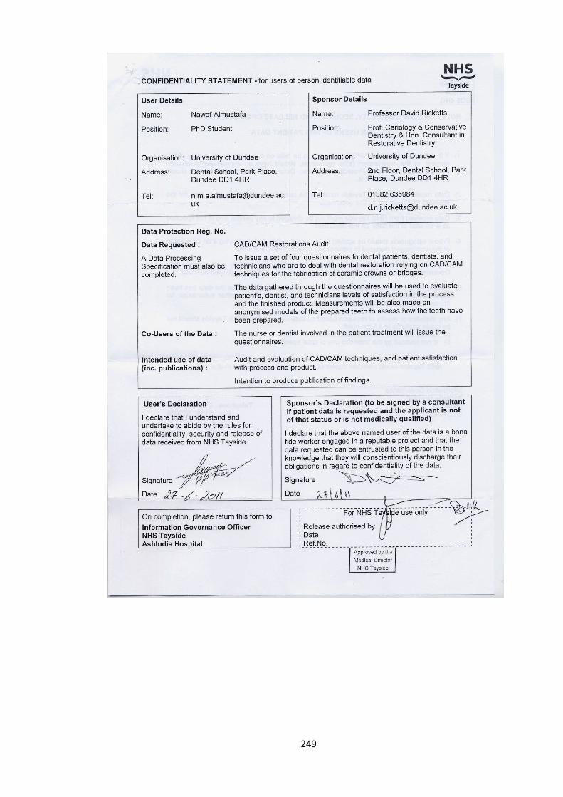
249
250
251