Embed Size (px)
Citation preview
University of Birmingham
Small Signal Stability of Fractional FrequencyTransmission System With Offshore Wind FarmsLi, Jing; Zhang, Xiao-ping
DOI:10.1109/TSTE.2016.2552540
License:Creative Commons: Attribution (CC BY)
Document VersionPublisher's PDF, also known as Version of record
Citation for published version (Harvard):Li, J & Zhang, X 2016, 'Small Signal Stability of Fractional Frequency Transmission System With Offshore WindFarms', IEEE Transactions on Sustainable Energy, vol. 7, no. 4, pp. 1538-1546.https://doi.org/10.1109/TSTE.2016.2552540
Link to publication on Research at Birmingham portal
General rightsUnless a licence is specified above, all rights (including copyright and moral rights) in this document are retained by the authors and/or thecopyright holders. The express permission of the copyright holder must be obtained for any use of this material other than for purposespermitted by law.
•Users may freely distribute the URL that is used to identify this publication.•Users may download and/or print one copy of the publication from the University of Birmingham research portal for the purpose of privatestudy or non-commercial research.•User may use extracts from the document in line with the concept of ‘fair dealing’ under the Copyright, Designs and Patents Act 1988 (?)•Users may not further distribute the material nor use it for the purposes of commercial gain.
Where a licence is displayed above, please note the terms and conditions of the licence govern your use of this document.
When citing, please reference the published version.
Take down policyWhile the University of Birmingham exercises care and attention in making items available there are rare occasions when an item has beenuploaded in error or has been deemed to be commercially or otherwise sensitive.
If you believe that this is the case for this document, please contact [email protected] providing details and we will remove access tothe work immediately and investigate.
Download date: 13. Jan. 2022
1538 IEEE TRANSACTIONS ON SUSTAINABLE ENERGY, VOL. 7, NO. 4, OCTOBER 2016
Small Signal Stability of Fractional FrequencyTransmission System With Offshore Wind Farms
Jing Li and Xiao-Ping Zhang, Senior Member, IEEE
Abstract—Fractional frequency transmission system (FFTS) is arelatively new transmission technology that can be used to deliverthe energy from remote offshore wind farms, and it can increase thetransmission capacity through the reduced transmission frequency.However, the dynamic performance of a FFTS with the wind farmmay be different from that of a traditional ac transmission with thewind farm. In this paper, a doubly fed induction generator (DFIG)-based wind farm is connected to the main grid via the FFTS. Thedetailed dynamic model of the FFTS with wind farm is establishedfirst, and then the eigenvalue analysis is carried out to evaluatethe system dynamic damping performance. To verify the results ofeigenvalue analysis, dynamic simulations are carried out on a singlemachine infinite bus and a multimachine system. Both eigenvalueanalysis and simulations demonstrate that the FFTS will have anegative influence on the damping of the DFIG-based wind farmin comparison to that of the wind farm with the traditional actransmission system. However, with the control of cycloconverter,this problem can be easily overcome, and the damping performanceof wind farm with FFTS can be even better.
Index Terms—Cycloconverter, DFIG, Fractional frequencytransmission system (FFTS), small signal stability.
I. INTRODUCTION
W IND energy is considered to be one of the widely usedrenewable energy sources. The delivery of energy from
remote offshore wind farms to the transmission grid becomesa big challenge. To cope with this challenge, a few transmis-sion system schemes have been proposed, such as high voltagealternating current system (HVAC), high voltage direct currentsystem (HVDC) and fractional frequency transmission system(FFTS).
The FFTS [1] is a relatively new option. The concept ofFFTS was first proposed in 1994 [1]. It was designed to deliverthe hydro-power from the West China to the East China wherethe transmission distance ranges from 1000 to 2500 km [2]. Theobjective of FFTS is to increase the transmission system capacityby using lower frequency, e.g. 50/3 Hz [3]. The feasibility of
Manuscript received May 31, 2015; revised August 23, 2015 and December10, 2015; accepted March 22, 2016. Date of publication May 13, 2016; date ofcurrent version October 7, 2016. This work was supported in part by the EPSRCunder Grant EP/L017725/1, in part by the China Scholarship Council, and inpart by the Birmingham Siguang Li Scholarship. Paper no. TSTE-00468-2015.
J. Li was with the Department of Electronic, Electrical, and Computer En-gineering, University of Birmingham, Birmingham B15 2TT, U.K. He is nowwith the State Grid Energy Research Institute, Future Science and TechnologyPark, Beijing 102209, China (e-mail: [email protected]).
X.-P. Zhang is with the Department of Electronic, Electrical, and ComputerEngineering, University of Birmingham, Birmingham B15 2TT, U.K. (e-mail:[email protected]).
Color versions of one or more of the figures in this paper are available onlineat http://ieeexplore.ieee.org.
Digital Object Identifier 10.1109/TSTE.2016.2552540
FFTS was initially analyzed in [2], and the experimental FFTSwas also established to confirm the advantages of FFTS [4].The core electrical component in a FFTS is the cycloconverter,which is used to convert the low frequency power to the nominalfrequency power. Initially, the cycloconverter was used to drivemachines in high power applications. The vector control ofcycloconverter in machine drives was introduced in [5], [6]. Thedynamics of cycloconverter and designed the feedback controlfor the cycloconverter were presented in [7]. In [8], [9], theapplication of cycloconverter in the FFTS was studied. Besides,the cycloconverter was also used to control the wind turbines inorder to achieve optimal speed control in the FFTS [10].
In case of the offshore wind power transmission, FFTS ismore suitable due to the following reasons:
1) As the speed of the wind generation remains in the rangefrom 12 Hz to 18 Hz [10], [11], wind turbine can generatepower at this frequency without gearbox [12] or with verysmall ratio gearbox.
2) Compared with HVAC, the FFTS costs less in long dis-tance transmission considering the investment, mainte-nance and power losses [3]. Specifically, in the offshorewind transmission, the breakeven distance is not exceed-ing 50 km via HVAC because of the submarine cable [13].
3) As for HVDC, though it can break through the bottleneckof the transmission distance, it still faces many economicaland technical challenges. The power converters at the twoends of HVDC are very expensive and difficult to main-tain, especially for the offshore wind farms [13]. In [14], acomprehensive evaluation between FFTS and HVDC wascarried out to support the above facts proposed in [13].In addition, the DC fault management for VSC HVDCsystem at present is still challenging and expensive.
4) On the other hand, the implementation of FFTS seemsto face no special technical difficulty. The key compo-nent, cycloconverter, which is used to transform powerfrequency, is a mature technology [4]. The single phaseFFTS have been developed for railway grid in Austriaand Switzerland [12]. There is comprehensive industrialknowledge available. Moreover, the FFTS can easily forma network as the conventional AC system does.
In this paper, the FFTS is chosen to deliver the remote off-shore wind energy to the main grid. The objectives of this paperare to carry out eigenvalue analysis to investigate the small sig-nal dynamics of such a system; analyze and improve the systemdamping performance; and use time domain simulations to val-idate the results.
This paper is organized as follows. In Section II, the prin-ciple of FFTS and the structure of the studied systems are
1949-3029 © 2016 IEEE. Translations and content mining are permitted for academic research only. Personal use is also permitted, but republication/redistributionrequires IEEE permission. See http://www.ieee.org/publications standards/publications/rights/index.html for more information.
LI AND ZHANG: SMALL SIGNAL STABILITY OF FRACTIONAL FREQUENCY TRANSMISSION SYSTEM 1539
introduced. The detailed mathematical models of the studiedsystems are depicted in Section III. Section IV conducts theeigenvalue analysis. Section V proposes a feedback control loopon the cycloconverter to improve the damping of the FFTS withwind farms. The time domain simulations are presented in Sec-tion VI to verify the results of the eigenvalue analysis and theproposed feedback control.
II. PRINCIPLE AND STRUCTURE
The FFTS, is also referred to as low frequency AC system, isanother method to increase the transmission capacity. Fractionalfrequency or low frequency means the transmission frequency islower than the nominal one. To make it more clear, the principleof the FFTS will be introduced as follows.
A. Basic Principle
In an AC transmission system, the active power transmittedvia the transmission line can be expressed as [15]
P =ES ER
Xsin δ (1)
where P is the positive power; ES and ER are the sending andreceiving end voltage, respectively; δ is the transmitting angle;X is the transmission line reactance and it is proportional to thepower frequency f,
X = 2πfL (2)
where L is the total inductance of the transmission line.According to (1), there are two methods to increase the trans-
mission capacity. One is to increase the voltage level, and theother one is to reduce the reactance. The strategy the FFTSadopts is the latter one. Due to the lower frequency, the totalreactance of the transmission line in FFTS can be reduced ap-parently according to (2). This is the basic operating principleof the FFTS.
Besides, the voltage drop of a transmission line can be eval-uated by [4]
ΔV % =QX
V 2 × 100 (3)
where Q is the reactive power of the transmission line.According to the above equation, the voltage drop of the trans-
mission line is proportional to the reactance of the transmissionline. So, the voltage fluctuation in the FFTS can be improved.
B. Structure of the Studied Systems
In the studied systems, the offshore wind farm is supposedto be composed of 100 2-MW, 0.69-kV doubly fed inductiongenerator (DFIG)-based wind turbines.
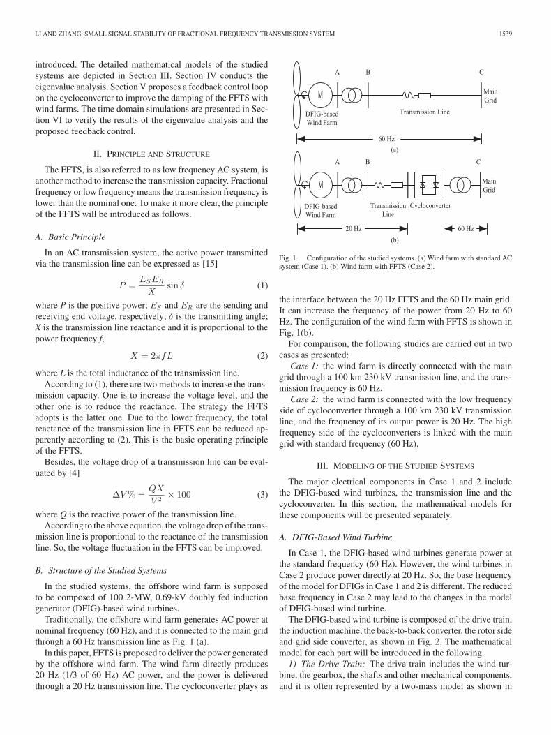
Traditionally, the offshore wind farm generates AC power atnominal frequency (60 Hz), and it is connected to the main gridthrough a 60 Hz transmission line as Fig. 1 (a).
In this paper, FFTS is proposed to deliver the power generatedby the offshore wind farm. The wind farm directly produces20 Hz (1/3 of 60 Hz) AC power, and the power is deliveredthrough a 20 Hz transmission line. The cycloconverter plays as
Fig. 1. Configuration of the studied systems. (a) Wind farm with standard ACsystem (Case 1). (b) Wind farm with FFTS (Case 2).
the interface between the 20 Hz FFTS and the 60 Hz main grid.It can increase the frequency of the power from 20 Hz to 60Hz. The configuration of the wind farm with FFTS is shown inFig. 1(b).
For comparison, the following studies are carried out in twocases as presented:
Case 1: the wind farm is directly connected with the maingrid through a 100 km 230 kV transmission line, and the trans-mission frequency is 60 Hz.
Case 2: the wind farm is connected with the low frequencyside of cycloconverter through a 100 km 230 kV transmissionline, and the frequency of its output power is 20 Hz. The highfrequency side of the cycloconverters is linked with the maingrid with standard frequency (60 Hz).
III. MODELING OF THE STUDIED SYSTEMS
The major electrical components in Case 1 and 2 includethe DFIG-based wind turbines, the transmission line and thecycloconverter. In this section, the mathematical models forthese components will be presented separately.
A. DFIG-Based Wind Turbine
In Case 1, the DFIG-based wind turbines generate power atthe standard frequency (60 Hz). However, the wind turbines inCase 2 produce power directly at 20 Hz. So, the base frequencyof the model for DFIGs in Case 1 and 2 is different. The reducedbase frequency in Case 2 may lead to the changes in the modelof DFIG-based wind turbine.
The DFIG-based wind turbine is composed of the drive train,the induction machine, the back-to-back converter, the rotor sideand grid side converter, as shown in Fig. 2. The mathematicalmodel for each part will be introduced in the following.
1) The Drive Train: The drive train includes the wind tur-bine, the gearbox, the shafts and other mechanical components,and it is often represented by a two-mass model as shown in

1540 IEEE TRANSACTIONS ON SUSTAINABLE ENERGY, VOL. 7, NO. 4, OCTOBER 2016
Fig. 2. Diagram of DFIG-based wind turbine.
Fig. 3. Two-mass model of drive train.
Fig. 3. The total moment of inertia of the drive train can beobtained by [16]
J =Jt
(NGB )2 + Jg (4)
where J is the total moment of inertia of the drive train; Jt isthe moment of inertia of the wind turbine; Jg is the moment ofinertia of the generator; NGB is the gearbox ratio.
Then, the total inertia constant of the drive train can be derivedas
H = Ht + Hg = Jt(ωb)
2
2S(NGB )2 + Jg(ωb)
2
2S(5)
where H is the total inertia constant of drive train; Ht is theinertia constant of the wind turbine; Hg is the inertia constant ofthe generator; ωb is the angular velocity of the base frequency;S is the nominal apparent power of the generator.
In Case 2, the DFIGs generate power at 1/3 of the standardfrequency, so the base frequency and the gearbox ratio bothdecrease to 1/3 of those in Case 1. According to (5), as for Case 2,the inertia constant of wind turbine Ht remains the same, and theinertia constant of generator Hg decrease greatly. Consequently,the total inertia constant of the drive train is reduced when theDFIGs are integrated via FFTS.
The mathematical model of the two-mass drive train can bedemonstrated as [17]
xwt = fwt (xwt, uwt) (6)
where xwt = [ωt, θtw , ωr ]T , uwt = [Te ]T ; ωt is the angle speedof the wind turbine; ωr is the angle speed of the ro-tor of generator; θtw is the shaft twist angle; Te is theelectromagnetic torque.
Fig. 4. Control block diagram of rotor-side converter.
Fig. 5. Control block diagram of grid-side converter.
2) Induction Generator: The generator of DFIG is a woundrotor induction machine. The 4th order model of the inductiongenerator, in the d-q reference, is given by [17]
xg = fg (xg ,zg ,u) (7)
where xg = [ids , iqs , Ed, Eq ]T , zg = [vdr , vqr ]T ,u = [vds ,vqs ]T , E′
d and E ′q are the d and q axis voltages behind the
transient reactance, respectively; ids and iqs are the d and qaxis stator currents, respectively; vds and vqs are the d and qaxis stator voltages, respectively; vdr and vqr are the d andq axis rotor voltages.
3) Back-to-Back Converter: The energy is balanced in thisconverter, so the following equations can be obtained,
CvDCdvDC
dt= vdg idg + vqg iqg − (vdr idr + vqr iqr ) (8)
where vdg and vqg are the d and q axis voltages of the grid-sideconverter; idg and iqg are the d and q axis currents of the grid-side converter; idr and iqr are the d and q axis rotor currents;vDC is the DC capacitor voltage; C is the capacitance of the DCcapacitor.
4) Converter Controls: The objective of the rotor side con-verter is to control the electromagnetic torque and the reactivepower of the DFIG. The grid side converter is responsible formaintaining the DC link voltage and controlling the reactivepower of the terminal.
The control block diagram of the rotor side converter and gridside converter are shown in Figs. 4 and 5 respectively. x1 , x2 , x3and x4 are the intermediate variables in the controller of rotor
LI AND ZHANG: SMALL SIGNAL STABILITY OF FRACTIONAL FREQUENCY TRANSMISSION SYSTEM 1541
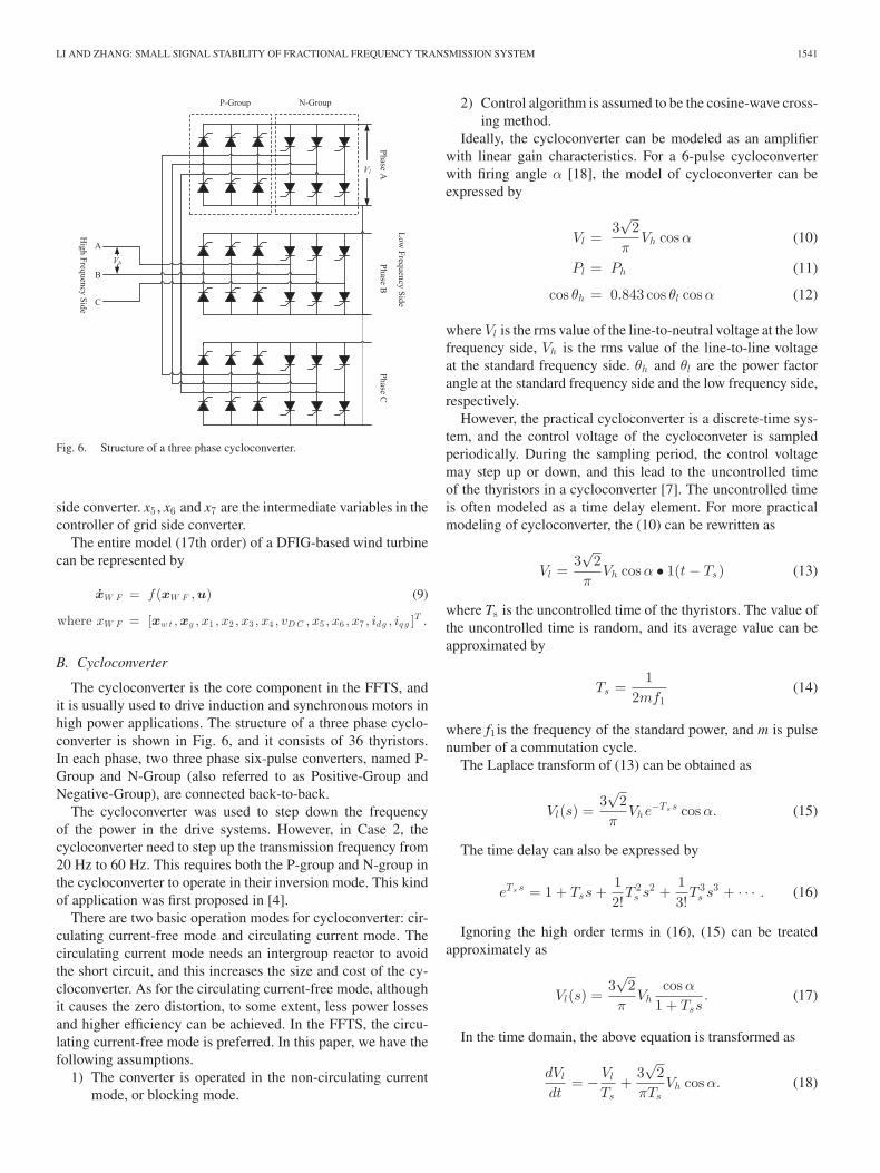
Fig. 6. Structure of a three phase cycloconverter.
side converter. x5 , x6 and x7 are the intermediate variables in thecontroller of grid side converter.
The entire model (17th order) of a DFIG-based wind turbinecan be represented by
xW F = f (xW F , u) (9)
where xW F = [xw t , xg , x1 , x2 , x3 , x4 , vD C , x5 , x6 , x7 , idg , iq g ]T .
B. Cycloconverter
The cycloconverter is the core component in the FFTS, andit is usually used to drive induction and synchronous motors inhigh power applications. The structure of a three phase cyclo-converter is shown in Fig. 6, and it consists of 36 thyristors.In each phase, two three phase six-pulse converters, named P-Group and N-Group (also referred to as Positive-Group andNegative-Group), are connected back-to-back.
The cycloconverter was used to step down the frequencyof the power in the drive systems. However, in Case 2, thecycloconverter need to step up the transmission frequency from20 Hz to 60 Hz. This requires both the P-group and N-group inthe cycloconverter to operate in their inversion mode. This kindof application was first proposed in [4].
There are two basic operation modes for cycloconverter: cir-culating current-free mode and circulating current mode. Thecirculating current mode needs an intergroup reactor to avoidthe short circuit, and this increases the size and cost of the cy-cloconverter. As for the circulating current-free mode, althoughit causes the zero distortion, to some extent, less power lossesand higher efficiency can be achieved. In the FFTS, the circu-lating current-free mode is preferred. In this paper, we have thefollowing assumptions.
1) The converter is operated in the non-circulating currentmode, or blocking mode.
2) Control algorithm is assumed to be the cosine-wave cross-ing method.
Ideally, the cycloconverter can be modeled as an amplifierwith linear gain characteristics. For a 6-pulse cycloconverterwith firing angle α [18], the model of cycloconverter can beexpressed by
Vl =3√
2π
Vh cos α (10)
Pl = Ph (11)
cos θh = 0.843 cos θl cos α (12)
where Vl is the rms value of the line-to-neutral voltage at the lowfrequency side, Vh is the rms value of the line-to-line voltageat the standard frequency side. θh and θl are the power factorangle at the standard frequency side and the low frequency side,respectively.
However, the practical cycloconverter is a discrete-time sys-tem, and the control voltage of the cycloconveter is sampledperiodically. During the sampling period, the control voltagemay step up or down, and this lead to the uncontrolled timeof the thyristors in a cycloconverter [7]. The uncontrolled timeis often modeled as a time delay element. For more practicalmodeling of cycloconverter, the (10) can be rewritten as
Vl =3√
2π
Vh cos α • 1(t − Ts) (13)
where Ts is the uncontrolled time of the thyristors. The value ofthe uncontrolled time is random, and its average value can beapproximated by
Ts =1
2mf1(14)
where f1 is the frequency of the standard power, and m is pulsenumber of a commutation cycle.
The Laplace transform of (13) can be obtained as
Vl(s) =3√
2π
Vhe−Ts s cos α. (15)
The time delay can also be expressed by
eTs s = 1 + Tss +12!
T 2s s2 +
13!
T 3s s3 + · · · . (16)
Ignoring the high order terms in (16), (15) can be treatedapproximately as
Vl(s) =3√
2π
Vhcos α
1 + Tss. (17)
In the time domain, the above equation is transformed as
dVl
dt= − Vl
Ts+
3√
2πTs
Vh cos α. (18)
1542 IEEE TRANSACTIONS ON SUSTAINABLE ENERGY, VOL. 7, NO. 4, OCTOBER 2016
TABLE ISELECTED EIGENVALUES OF DFIG-BASED WIND FARM
WITH FFTS AND STANDARD AC SYSTEM
Dominant States Case 1(60 Hz) Damping Case 2(20 Hz) Damping
id s , iq s –79.54 ± 383.67i 20.30% –26.50 ± 193.22i 13.60%id g , iq g –1.35 ± 377.30i 0.36% –0.03 ± 128.16i 0.02%E ′
d , E ′q –4.56 ± 17.66i 25.00% –0.70 ± 13.11i 5.33%
ωr –6.05 ± 18.58i 31.00% –2.41 ± 13.58i 17.10%vD C –1.09 ± 7.49i 14.40% –0.16 ± 4.40i 3.63%
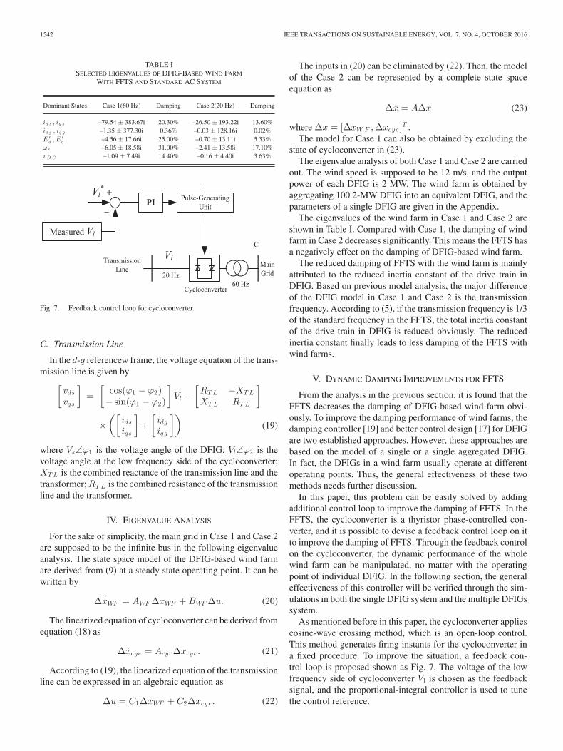
Fig. 7. Feedback control loop for cycloconverter.
C. Transmission Line
In the d-q referencew frame, the voltage equation of the trans-mission line is given by
[vds
vqs
]=
[cos(ϕ1 − ϕ2)− sin(ϕ1 − ϕ2)
]Vl −
[RT L −XT L
XT L RT L
]
×([
ids
iqs
]+
[idg
iqg
])(19)
where Vs∠ϕ1 is the voltage angle of the DFIG; Vl∠ϕ2 is thevoltage angle at the low frequency side of the cycloconverter;XT L is the combined reactance of the transmission line and thetransformer; RT L is the combined resistance of the transmissionline and the transformer.
IV. EIGENVALUE ANALYSIS
For the sake of simplicity, the main grid in Case 1 and Case 2are supposed to be the infinite bus in the following eigenvalueanalysis. The state space model of the DFIG-based wind farmare derived from (9) at a steady state operating point. It can bewritten by
ΔxWF = AWF ΔxWF + BWF Δu. (20)
The linearized equation of cycloconverter can be derived fromequation (18) as
Δxcyc = AcycΔxcyc . (21)
According to (19), the linearized equation of the transmissionline can be expressed in an algebraic equation as
Δu = C1ΔxWF + C2Δxcyc . (22)
The inputs in (20) can be eliminated by (22). Then, the modelof the Case 2 can be represented by a complete state spaceequation as
Δx = AΔx (23)
where Δx = [ΔxW F ,Δxcyc ]T .The model for Case 1 can also be obtained by excluding the
state of cycloconverter in (23).The eigenvalue analysis of both Case 1 and Case 2 are carried
out. The wind speed is supposed to be 12 m/s, and the outputpower of each DFIG is 2 MW. The wind farm is obtained byaggregating 100 2-MW DFIG into an equivalent DFIG, and theparameters of a single DFIG are given in the Appendix.
The eigenvalues of the wind farm in Case 1 and Case 2 areshown in Table I. Compared with Case 1, the damping of windfarm in Case 2 decreases significantly. This means the FFTS hasa negatively effect on the damping of DFIG-based wind farm.
The reduced damping of FFTS with the wind farm is mainlyattributed to the reduced inertia constant of the drive train inDFIG. Based on previous model analysis, the major differenceof the DFIG model in Case 1 and Case 2 is the transmissionfrequency. According to (5), if the transmission frequency is 1/3of the standard frequency in the FFTS, the total inertia constantof the drive train in DFIG is reduced obviously. The reducedinertia constant finally leads to less damping of the FFTS withwind farms.
V. DYNAMIC DAMPING IMPROVEMENTS FOR FFTS
From the analysis in the previous section, it is found that theFFTS decreases the damping of DFIG-based wind farm obvi-ously. To improve the damping performance of wind farms, thedamping controller [19] and better control design [17] for DFIGare two established approaches. However, these approaches arebased on the model of a single or a single aggregated DFIG.In fact, the DFIGs in a wind farm usually operate at differentoperating points. Thus, the general effectiveness of these twomethods needs further discussion.
In this paper, this problem can be easily solved by addingadditional control loop to improve the damping of FFTS. In theFFTS, the cycloconverter is a thyristor phase-controlled con-verter, and it is possible to devise a feedback control loop on itto improve the damping of FFTS. Through the feedback controlon the cycloconverter, the dynamic performance of the wholewind farm can be manipulated, no matter with the operatingpoint of individual DFIG. In the following section, the generaleffectiveness of this controller will be verified through the sim-ulations in both the single DFIG system and the multiple DFIGssystem.
As mentioned before in this paper, the cycloconverter appliescosine-wave crossing method, which is an open-loop control.This method generates firing instants for the cycloconverter ina fixed procedure. To improve the situation, a feedback con-trol loop is proposed shown as Fig. 7. The voltage of the lowfrequency side of cycloconverter Vl is chosen as the feedbacksignal, and the proportional-integral controller is used to tunethe control reference.

LI AND ZHANG: SMALL SIGNAL STABILITY OF FRACTIONAL FREQUENCY TRANSMISSION SYSTEM 1543
Fig. 8. Dynamic responses of wind farm for Case 1, 2, and 3 under fault.
To verify the effectiveness, the proposed control loop is im-plemented in the FFTS in the following simulations. It is testedin both SMIB and multi-machine system.
VI. DYNAMIC SIMULATIONS
To verify the results of eigenvalue analysis and the pro-posed controller, the dynamic simulations are carried out in
Fig. 9. Voltage profile at Bus B for Case 1, 2, and 3 under fault.
PSCAD/EMTDC. The following simulations are conducted ina single machine infinite bus (SMIB) and a multi-machine sys-tem, respectively. The dynamic responses are compared betweenthe FFTS with wind farms and the conventional AC system withwind farms.
A. Simulations on SMIB System
In this part, the wind farm is obtained by aggregating100 2-MW DFIG into an equivalent DFIG. The simulationsare carried out in SMIB to observe the dynamic responses in thefollowing three cases:
Case 1 and Case 2: as described in Section II. The main gridis substituted by an infinite bus.
Case 3: a control feedback loop is added to cycloconverterin the FFTS with DFIG-based wind farm (Case 2).
1) Dynamic Responses Against Disturbances: In order tostudy the dynamics of Case 1 and Case 2, a three-phase groundfault is applied to excite the corresponding dynamic responses.The three-phase ground fault happens at Bus Bin both cases asshown in Fig. 1. It starts at 6.0 s during the simulation, and thenit is cleared after 0.025 s.
Fig. 8 shows the dynamic responses of the active power,reactive power, rotor speed, DC-link voltage of the DFIG in Case1 and Case 2. From the dynamic responses, it can be concludedthat the damping of the wind farm with the FFTS decreasesignificantly compared with the wind farm with conventionalAC system.
Fig. 9 shows the voltage profile at Bus B after the fault. In theFFTS, the voltage fluctuation at Bus B is improved comparedwith that in the standard AC system. According to (3), the im-proved voltage fluctuation is attributed to the reduced reactanceof the transmission line in the FFTS.
2) Damping Improvement for FFTS: From previous simula-tions, it is observed that the FFTS reduces the damping of windfarms significantly compared with standard AC system. To im-prove the damping of FFTS, an additional feedback control loopon cycloconverter is proposed as Fig. 7, and its effectiveness isalso verified through the simulations in SMIB. The same faultin Case 1 and Case 2 is also applied in Case 3.

1544 IEEE TRANSACTIONS ON SUSTAINABLE ENERGY, VOL. 7, NO. 4, OCTOBER 2016
Fig. 10. Configuration of the simulations in four-machine system.
Fig. 8 compares the dynamic responses of the active power,reactive power, rotor speed, DC-link voltage in Case 3 with thosein Case 1 and Case 2. With the support from additional controlleron cycloconverter, the damping of the wind farm with FFTS isgreatly improved, and it can be even better than the wind farmwith standard AC system. The simulation results also indicatethat the problem of less damping in the FFTS can be easilysolved by adding feedback control loop.
Fig. 9 compares the voltage at Bus B in Case 3 with those inCase 1 and 2. The voltage fluctuation can be further improvedwith the additional controller on the cycloconverter.
B. Simulations on Multi-Machine System
To further verify the general effectiveness of the small signalanalysis and the proposed controller, the simulations will beconducted in the four-machine system. The four-machine sys-tem is shown as Fig. 10, and the details of system can be foundin [15].
Moreover, the wind farm in previous section is divided intotwo wind farms: WF1 and WF2. Each wind farm includes 50DFIG, but the wind speed is different for each one. The windspeed for WF1 is 10.903 m/s, and the output power for a singleDFIG is 1.5 MW. The WF2 is under 12 m/s wind speed, and theoutput power for a DFIG is 2 MW.
For comparison, simulations are carried out in the followingthree cases:
Case 4: the WF1 and WF2 are directly connected to B6 (asin Fig. 10) through a 100 km 230 kV standard AC transmissionline.
Case 5: the WF1 and WF2 are integrated with the four-machine system through a 100 km 230 kV low frequency trans-mission line. The low frequency side of the cycloconverter isconnected to B12, and the high frequency side is linked with B6in the four-machine system.
Case 6: based on Case 5, the proposed controller is imple-mented on cycloconverter as shown in Fig. 7.
In Case 4, 5 and 6, the total output power of WF1 and WF2is 175 MW. Consequently, the output of G1 is reduced by 175MW to guarantee the overall output from G1 and wind farmremain 900 MW.
1) Dynamic Responses Against Disturbances: The three-phase ground fault happens at B8 as shown in Fig. 9. It starts at6.0 s in both Case 4 and Case 5, and then it is cleared after 0.1 s.
Fig. 11. Dynamic responses of WF1 and WF2 for Case 4, 5, and 6 under fault.

LI AND ZHANG: SMALL SIGNAL STABILITY OF FRACTIONAL FREQUENCY TRANSMISSION SYSTEM 1545
TABLE IIEIGENVALUES OF DFIG-BASED WIND FARMS IN CASE 4 AND CASE 5
Dominant States Case 4 (60 Hz) Damping Case 5 (20 Hz) Damping
id s , iq s (WF1) –61.60 ± 377.84i 16.10% –24.10 ± 168.52i 14.20%id g , iq g (WF1) –5.06 ± 375.79i 1.35% –0.8 ± 125.23i 0.64%E ′
d , E ′q (WF1) –6.90 ± 33.89i 20.00% –1.83 ± 19.48i 9.35%
ωr (WF1) –2.87 ± 16.58i 17.10% –0.97 ± 9.67i 9.98%vD C (WF1) –1.64 ± 7.93i 20.30% –0.29 ± 5.18i 5.59%id s , iq s (WF2) –39.10 ± 377.84i 10.30% –13.90 ± 168.52i 8.22%id g , iq g (WF2) –5.04 ± 375.77i 1.34% –0.75 ± 125.24i 0.60%E ′
d , E ′q (WF2) –6.94 ± 33.92i 20.00% –1.84 ± 19.46i 9.41%
ωr (WF2) –2.87 ± 16.59i 17.00% –0.96 ± 9.67i 9.88%vD C (WF2) –1.77 ± 8.89i 19.5% –1.04 ± 5.78i 17.70%
Fig. 12. Voltage profile at Bus B12 for Case 4, 5, and 6 under fault.
Fig. 11 demonstrates the dynamic responses of the activepower and reactive power in both WF1 and WF2 for Case 4and Case 5. The state responses in the four-machine systemalso indicate that the damping of the DFIG-based wind farmwith the FFTS decrease significantly compared with that of thewind farm with traditional AC system, which is the same as thesimulation results in SMIB. The eigenvalues of the wind farmsin Case 4 and Case 5, as shown in Table II, also confirm theabove result.
Fig. 12 shows the voltage profile at Bus B12 in Case 4 andCase 5, and it also indicates that the voltage response is improvedin the FFTS.
2) Damping Improvement for FFTS: The effectiveness ofthe proposed controller on the cycloconverter is also tested inthe four-machine system.
Fig. 11 shows the dynamic responses of the active and reactivepower in both WF1 and WF2 in Case 6. From the dynamicresponses of Case 6, the cycloconverter with additional controlcan greatly improve the damping of the wind farm with FFTS.Meanwhile, with the help of cycloconverter, the damping ofwind farm with FFTS can perform better than that of the windfarm with the traditional AC transmission system.
Fig. 12 demonstrates that the feedback controller on thecycloconverter can further improve voltage fluctuation atBus B12.
VII. CONCLUSION
This paper has applied the FFTS to deliver the power gen-erated by a DFIG-based offshore wind farm to the main trans-mission grid. The mathematical model of the FFTS has beenproposed in detail. Based on the model established, eigenvalueanalysis has been conducted to investigate the dynamics of theDFIG-based wind farm with FFTS. The time domain simula-tions have also been conducted in the SMIB and four-machinesystem to verify the results of the eigenvalue analysis. Botheigenvalue analysis and time domain simulations have demon-strated that the damping of the DFIG-based wind farm is greatlydecreased by utilizing the FFTS in comparison with the windfarm with the traditional AC transmission system. However, thisproblem can be easily overcome by adding control loop to thecycloconverter. With the control loop, the damping of the windfarm with FFTS can perform better than that of the wind farmwith with traditional AC system.
APPENDIX
A. Data of the DFIG-Based Wind Turbine
1) Per unit system: Sb = 2.2 MW, Vb = 0.69 kV.2) Wind Turbine: Vw =12m/s, Cp =0.4382, R=37.049m,
ρ=1.225 kg/m3 ,Ht =1 s.3) The generator of DFIG:
Rs = 0.00462 pu, Lm = 4.348 pu, Lss = 4.450 pu,
Lrr = 4.459 pu, Rr = 0.006007 pu,Hg = 0.5 s.
4) Converter:C = 0.11F, vDC = 1.5 kV, Lg =0.3 pu, Rg = 0.003 pu.
5) Control parameter: Kp 1 = 0.5, Ti1 = 0.4,Kp 2 = 0.025,Ti2 = 0.075,Kp 3 = 0.5, Ti3 = 0.4,Kp 4 = 1, Ti4 =0.05,Kp 5 = 0.8, Ti5 = 0.032.
B. Data of the Transmission Line
Length of the transmission line: 100 kmLine-to-line RMS voltage: 230 kVCombined resistance of the transformer and transmission line:RT L = 5ΩCombined inductance of the transformer and transmission
line: LT L = 0.13H
C. Parameters of the Controller on Cycloconverter
Kp = 100, Ti = 0.01
REFERENCES
[1] X. Wang, “The fractional frequency transmission system,” in Proc. IEEEJpn. Power Energy, Tokyo, Japan, Jul. 1994, pp. 53–58.
[2] X. Wang and X. Wang, “Feasibility study of fractional transmission sys-tem,” IEEE Trans. Power Syst., vol. 11, no. 2, pp. 962–967, May 1996.
[3] X. Wang, X. Wang, and Y. Teng, “Fractional frequency transmission sys-tem and its application,” Proc. CSEE, vol. 32, no. 13, pp. 1–6, May 2012.
[4] X. Wang, C. Cao, and Z. Zhou, “Experiment on fractional frequencytransmission system,” IEEE Trans. Power Syst., vol. 21, no. 1, pp. 372–377, Feb. 2006.

1546 IEEE TRANSACTIONS ON SUSTAINABLE ENERGY, VOL. 7, NO. 4, OCTOBER 2016
[5] B. K. Bose, Modern Power Electronics and AC Drives. Englewood Cliffs,NJ, USA: Prentice-Hall, 2002.
[6] S. P. Da and A. K. Chattopadhyay, “Observer-based stator-flux-orientedvector control of cycloconverter-fed synchronous motor drive,” IEEETrans. Ind. Appl., vol. 33, no. 4, pp. 943–955, Jul./Aug. 1997.
[7] W. Hill, E. Ho, and I. Neuzil, “Dynamic behaviour of a cycloconvertersystem,” in Proc. IEEE Ind. Appl. Soc. Annu. Meet., 1990, pp. 1024–1030.
[8] Y. Cho, G. J. Cokkinides, and A. P. Meliopoulos, “Time domain simulationof a three-phase cycloconverter for LFAC transmission systems,” in Proc.Power Energy Soc. Trans. Distrib. Conf. Exhib., Orlando, FL, USA, May2012, pp. 1–7.
[9] Y. Teng and X. Wang, “Three-phase short-circuit fault on the lower fre-quency bus of cycloconverter in FFTS,” in Proc. Power Syst. Conf. Expo.,2009, pp. 1–5.
[10] Z. Song, X. Wang, Y. Teng, L. Ning, and Y. Meng, “Optimal control studyfor fractional frequency wind power system,” in Proc. Asia-Pacific PowerEnergy Eng. Conf., 2012, pp. 1–5.
[11] L. Ning, X. Wang, and Y. Teng, “Experiment on wind power grid inte-gration via fractional frequency transmission system: Realization of thevariable-speed variable-frequency power wind,” in Proc. 4th Int. Conf.Electr. Utility Deregulation Restruct. Power Technol., Jul. 2011, pp. 444–449.
[12] W. Fischer, R. Braun, and I. Erlich, “Low frequency high voltage off-shore grid for transmission of renewable power,” in Proc. IEEE 3rd PESInnovative Smart Grid Technol. Eur., Berlin, Germany, 2012, pp. 1–6.
[13] Q. Nan, Y. Shi, X. Zhao, and A. Vladislav, “Offshore wind farm connectionwith low frequency AC transmission technology,” in Proc. Power EnergySoc. General Meet., 2009, pp. 1–8.
[14] S. A. P. Meliopoulos, D. Aliprantis, Y. Cho, D. Zhao, A. Keeli, and H.Chen, “Low frequency transmission,” Final Project Report, PSERC Pub-lication 12-28, Oct. 2012, Power Systems Engineering Research Center,Arizona State Univ., 527 Engineering Research Center, Tempe, AZ, USA.
[15] P. Kundur, Power System Stability and Control. New York, NY, USA:McGraw-Hill, 1994.
[16] S.M. Muyeen, M. H. Ali, R. Takahashi, T. Murata, J. Tamura, Y. Tomaki,A. Sakahara, and E. Sasano, “Comparative study on transient stabilityanalysis of wind turbine generator system using different drive train mod-els,” IET Renewable Power Generation. vol. 1, no. 2, pp. 131–141, 2007.
[17] F. Wu, X.-P. Zhang, K. Godfrey, and P. Ju, “Small signal stability analysisand optimal control of a wind turbine with doubly fed induction generator,”IET Generation Transmiss. Distrib. vol. 1, no. 5, pp. 751–760, Sep. 2007.
[18] B. R. Pelly, Thyristor Phase-Controlled Converters and Cycloconverters.New York, NY, USA: Wiley, 1971.
[19] Y. Mishra, S. Mishra, M. Tripathy, N. Senroy, and Z. Y. Dong, “Im-proving stability of a DFIG-based wind power system with tuned damp-ing controller,” IEEE Trans. Power Syst., vol. 24, no. 3, pp. 650–660,Sep. 2009.
Jing Li received the B.Eng. degree from Chongqing University, Chongqing,China, and the M.Eng. degree from the University of Science and Technologyof China, Hefei, China, in 2009 and 2012, respectively. He obtained the Ph.D de-gree in electrical engineering from the University of Birmingham, Birmingham,U.K. in 2016. He is now with the Department of Corporate Strategy Research,State Grid Energy Research Institute.
Xiao-Ping Zhang (M’95–SM’06) received the B.Eng., M.Sc., and Ph.D. de-grees in electrical engineering from Southeast University, Nanjing, China, in1988, 1990, 1993, respectively. He is currently a Professor of electrical powersystems at the University of Birmingham, Birmingham, U.K. He is also theDirector of Smart Grid, Birmingham Energy Institute and the Co-Director ofBirmingham Energy Storage Centre. Before joining the University of Birm-ingham, he was an Associate Professor at the University of Warwick, England,U.K. From 1998 to 1999, he was visiting UMIST. From 1999 to 2000, he was anAlexander-von-Humboldt Research Fellow with the University of Dortmund,Germany. Between 1993 and 1998, he worked at the China State Grid EPRI(NARI Group) on EMS/DMS advanced application software research and de-velopment. He is the co-author of the 1st and 2nd edition of the monograph“Flexible AC Transmission Systems: Modeling and Control,” (Springer, 2006,2012) and “Restructured Electric Power Systems: Analysis of Electricity Mar-kets with Equilibrium Models,” (IEEE Press/Wiley, 2010). Internationally, hepioneered the concept of “Energy Union” and “UK’s Energy Valley.”