Embed Size (px)
Citation preview

MultiCraft International Journal of Engineering, Science and TechnologyVol. 8, No. 3, 2016, pp. 48-63
INTERNATIONALJOURNAL OF
ENGINEERING,SCIENCE ANDTECHNOLOGYwww.ijest-ng.com
www.ajol.info/index.php/ijest 2016 MultiCraft Limited. All rights reserved
Enhancement of small signal stability of a DFIG-based wind power systemusing fuzzy logic control
T. K. Renuka 1*, P. Reji 2, Sasidharan Sreedharan3
1*Department of Electrical & Electronics Engineering, M E S College of Engineering, Kuttippuram, Kerala, INDIA2 Department of Electrical & Electronics Engineering, Government Engineering College, Thrissur, Kerala, INDIA
3 Department of Electrical & Electronics Engineering, M E S College of Engineering, Kuttippuram, Kerala, INDIA*Corresponding Author: e-mail: [email protected], Tel +91-9446054391
Abstract
This paper proposes fuzzy logic controllers for enhancing the small signal stability of DFIG-based wind integrated powersystem. The test system used is single machine infinite bus system integrated with conventional proportional-integral controllers.The fuzzy logic controllers provide optimum proportional and integral gains under various operating conditions namely windspeed and grid strength. The effects of strong and weak grid strengths have been taken into account with short circuit level of 40MVA and 16 MVA, respectively. The obtained result justifies that the damping ratio and there by the small signal stability ofsuch a system have been enhanced considerably by the action of fuzzy logic controllers. The generalization can be enlarged tomulti-machine systems in various dynamic conditions.
Keywords : Doubly Fed Induction Generator, small signal stability, state space model, eigenvalue analysis, fuzzy logic basedtuning circuits
DOI: http://dx.doi.org/10.4314/ijest.v8i3.5
1. Introduction
Generally, wind energy is judged as a renewable energy resource with great potentials the world over. The variable-speed windturbine generating systems provided with a doubly fed induction generator (DFIG) has been given increased interest in the last fewyears because of its noticeable advantages of improved efficiency, smooth grid connection, compact size, less mechanical stress,reduced cost of power electronic components and better control of active as well as reactive power when compared with otherwind turbine generator concepts (Mehta et al., 2014).
A DFIG-based wind energy generation system, comprises gear-box, wind turbine, wound rotor induction generator, grid-sideconverter (GSC) as well as rotor-side converter (RSC). Grid-side converter injects voltage to the grid at power frequency, leadingor lagging while RSC works at slip frequency (Ekanayake et al., 2003).To maintain stator terminal voltage, dc voltage level, GSCreactive power level and maximum power point tracking, proportional-integral (PI) controllers are generally used. The gains ofconventional PI controllers need to be tuned for varying operating conditions to obtain good performance.
Recently the integration of DFIG type wind turbines in to the grid has increased considerably which led to a growing concernabout its impact on the transient, voltage and small signal stability. Small changes in operating parameters of a power system canresult in electromechanical oscillations and if the system is not adequately damped the synchronism may be lost (Ekanayake et al.,2003). The analysis of small signal stability of wind integrated power system is emerging as a promising area. To simulate theresponse of wind turbine, a dynamic model of DFIG with its control as well as protection circuits was developed by Ekanayake etal. (2003). It was established that the stability of DFIG has the potential to improve by the proper selection of the proportionalgains of the speed and power factor controllers. Holdsworth et al. (2003) discussed the dynamic modelling of large (MW) capacityfixed and variable speed induction generator wind turbines. Wu et al. (2007) optimized the parameters of the controllers of windturbine using the technique of particle swarm optimization. Improvement in the small signal as well as the system’s transient
Renuka et al./ International Journal of Engineering, Science and Technology, Vol. 8, No. 3, 2016, pp. 48-6349
stability employing optimized controller was reported. The work of Wang et al. (2008) discussed the eigenvalue analysis of theDFIG wind turbine system mainly focusing on the participation factor, frequency, and damping ratio. Elkington et al. (2008)obtained a third-order mathematical representation of DFIG and studied the behavioural patterns of the system when it is subjectedto disturbances. In their study, Tsourakis et al. (2009) introduced an extra damping to inter-area oscillations by incorporating awind power system stabilizer.
Mishra et al. (2009) proposed coordinated tuning of the damping controller using bacteria foraging technique for enhancing thedamping of the oscillatory modes of DFIG-based wind generation system. A thorough examination into the intrinsic attributes ofvarious types of induction generators using small-signal analyses was conducted by Kong et al. (2012). Cardenas at al. (2013)showcased a review of the DFIGs’ operation control systems as well as brushless DFIGs for applications in wind energy. Shawonet al. (2013) discussed small signal stability examination of a DFIG-based wind farm including series dynamic braking resistorconnected at the stator side. Bin et al. (2013) in their work analyzed the impacts of large scale integration of wind power on powersystem small-signal stability by modifying the 3-generator 9-bus WECC test system and Liao et al. (2013) modeled a DFIG-basedoffshore wind farm combined by the way of a voltage source converter–based high voltage direct current transmission system forsmall signal stability analysis. Mehta et al. (2014) analyzed the impact of penetration of DFIG-based wind power generation onoscillatory stability of two area interconnected power system and found that the oscillatory instability can be stabilized with thecoordinated operation of automatic voltage regulator (AVR) and power system stabilizer (PSS) equipped on synchronousgenerators. Mehta et al. (2015) found that the optimization of controller parameters of a DFIG-based wind generation systememploying particle swarm optimization technique minimized the oscillations in rotor currents and electromagnetic torque.Chatterjee et al. (2016) in their work used teaching learning based optimization (TLBO) algorithm to optimize the gains of PIcontrollers associated with DFIG and showed that the TLBO provides superior end results than PSO. Most of the works describedabove deals with the small signal stability enhancement of wind integrated system; however no such work points to an optimizedartificial intelligence based system with least computational cost. Even though PSO is computationally efficient, the expenseincurred is more due to the wide generalized search, whereas fuzzy logic method provides reasonable solution in least computationtime for such a system and hence being recommended and used in the current work. The advantage of Fuzzy logic controllers(FLC) are that they are knowledge based controllers and do not require a detailed mathematical modeling (Chauhan et al., 2016).In this paper simple fuzzy logic based tuning circuits are proposed which tune the controller gains under various operatingconditions and it seems to be more adequate for improving the small signal stability performance of system with DFIG.
This paper analyses the small signal stability performance of DFIG integrated to infinite bus under varying wind speed andvarying grid strength. The state space model of DFIG with torque and voltage controllers has been developed. The rest of thisarticle has been arranged in the following way. Section 2 describes the DFIG model while the controllers have been explained insection 3. Section 4 discusses the small-signal stability analysis with conventional controller parameters. The proposed fuzzy logictuning circuits have been explained in section 5. The results of eigenvalue analysis with tuned controller parameters andcomparison of the results with the performance using conventional controller parameters have been presented in Section 6 with theconclusion following in Section 7.
2. DFIG Model
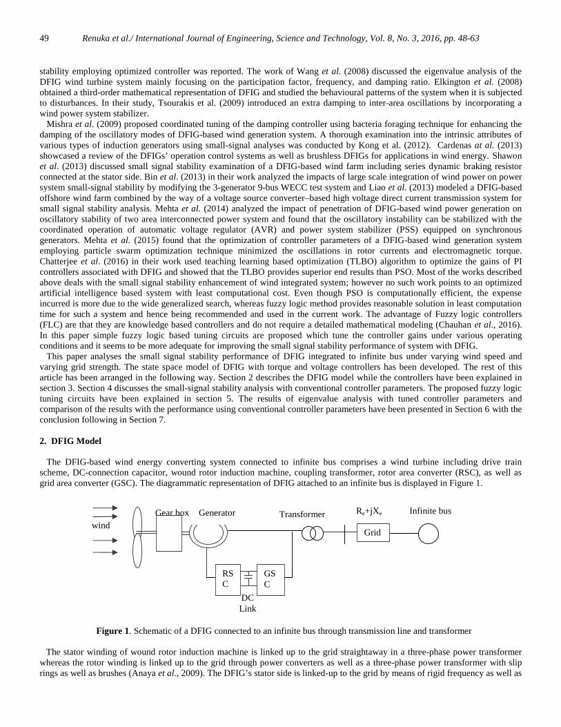
The DFIG-based wind energy converting system connected to infinite bus comprises a wind turbine including drive trainscheme, DC-connection capacitor, wound rotor induction machine, coupling transformer, rotor area converter (RSC), as well asgrid area converter (GSC). The diagrammatic representation of DFIG attached to an infinite bus is displayed in Figure 1.
Figure 1. Schematic of a DFIG connected to an infinite bus through transmission line and transformer
The stator winding of wound rotor induction machine is linked up to the grid straightaway in a three-phase power transformerwhereas the rotor winding is linked up to the grid through power converters as well as a three-phase power transformer with sliprings as well as brushes (Anaya et al., 2009). The DFIG’s stator side is linked-up to the grid by means of rigid frequency as well as
DCLink
windTransformerGear box Generator Re+jXe
Grid
Infinite bus
GSC
RSC

Renuka et al./ International Journal of Engineering, Science and Technology, Vol. 8, No. 3, 2016, pp. 48-6350
voltage, while the rotor area delivers an inconsistent frequency that is regulated with the power converters prior to connection tothe grid. The converters have the control ability for the real and the reactive power of generator by handling a part (25-30%) of thecomplete power (Kundur, 1994). The three-phase windings in the stator of the induction machine produce a synchronously revolving magnetic field. The dynamicequations for stator voltages in d–q reference frame rotating at synchronous speed are given by equations (1) and (2) and the rotorvoltages in d-q frame are given by equations (3) and (4).
)IX+)IX+((X+IR=V qrmqsmsdssds (1)
))(( drmdsmsqssqs IXIXXIRV (2)
)))((1( qsmqrmrrdrrdr IXIXXIRV (3)
)))((1( dsmdrmrrqrrqr IXIXXIRV (4)
where Ids and Iqs are direct and quadrature axes stator currents, Idr and Iqr are direct and quadrature axes rotor currents , Rs is thestator resistances, Rr is the rotor resistance , Xs is the stator reactance, Xm is the magnetising reactance , Xr is the rotor reactanceand ωr is the rotor speed. The wind turbine, generator shaft, and the gearbox are modelled in as a lumped inertia. The equation for motion can berepresented by equation (5).
emr TT=
dt
dω
tot2H
1 (5)
where Htot is the total inertia of generator rotor (Hgen) and wind turbine (Htur), Te is the electromagnetic torque and Tm is themechanical torque.The mechanical power Pm extracted from the wind (Wu et al., 2007) is given by equation (6).
3),(2
AVCP pm
(6)
where ρ is the air density, V is the wind speed, β is the pitch angle, A is the area swept by the rotor , λ is the blade tip speed ratioand Cp the power coefficient.Cp is given by equation (7).
iλ
ip eβc
λc
c=C/12.5
32
1 5
(7)
where λi is given by equation (8).
)1/(035.008.0/1
13
i (8)
C p (λ, β) has a maximum value for a particular tip speed ratio λopt and pitch angle β =0.
The mechanical Torque is given by equation (9).
mTm
mP
(9)
Also Tm can be written as given by equation (10) given below
)(
3)()(
pur
pupupm
VCT
(10)
Te - the electro-mechanical torque is given by equation (11)

Renuka et al./ International Journal of Engineering, Science and Technology, Vol. 8, No. 3, 2016, pp. 48-6351
)( dsqrqsdrme IIIIXT (11)
3. Controllers
The rotor-side converter (RSC) of DFIG, by using the quadrature axis and direct axis components of rotor currents regulates theelectromagnetic torque and terminal voltage of DFIG (Cardenas et al., 2013; Lihui et al., 2011). The idea of the torque controller isto adapt the electromagnetic torque of the generator according to wind speed so as to extract maximum power from wind. Figure 2shows the block diagram of the torque controller. For a particular rotor speed ωr , the reference torque Tref for maximum powerextraction can be obtained from wind turbine characteristics. With the computed value of Tref , a reference rotor current in q axisIqr_ref can be obtained as given by equation (12) (Mehta et al.,2015).
Figure 2. Torque control scheme of DFIG
refssm
srefqr T
VX
XI
_
(12)
The q axis component of rotor voltage Vqr required to operate DFIG at the torque Tref can be obtained by using a proportional-integral (PI) controller. The expression for q axis rotor voltage Vqr in terms of the parameters of PI controller is given by equation(13).
)()( __ qrrefqrptqrrefqritqr IIKdtIIKV (13)
where Kit and Kpt are the integral and proportional controller parameters respectively.The terminal voltage is directly proportional to the reactive power delivered to the grid. The complete block representation of the
DFIG terminal voltage controller is displayed in Figure 3. The terminal voltage (V) is compared with the reference voltage and thereference current (Idr_ref) get adjusted appropriately. The input to the PI controller is the difference between Idr_ref and Idr and theoutput is the required d-axis rotor voltage Vdr (Mehta et al., 2015).
Figure 3. Voltage control scheme of DFIG
X3 Idr_ref
(Vref –V)
V/(xmω)
KP ʃ+
-Kiv ʃ
Kpv
X2
Idr
++
Vdr
++
X1
Vqr (I qr_ref –Iqr)
Kpt
Kit ʃ ++

Renuka et al./ International Journal of Engineering, Science and Technology, Vol. 8, No. 3, 2016, pp. 48-6352
dtV)(VK=X refp 3 (14)
ωx
V+V)dt(VK=I
mrefprefdr (15)
dt)I(IK=X drrefdriv 2 (16)
)I(IK+X=V drrefdrpvdr 2 (17)
where Kpv and Kiv are the proportional and integral controller parameters of voltage controller respectively.
When integrating DFIG to the transmission network, the stator voltage can be written as given by equations (18) and (19).
dsTqsTdds IRIXVV (18)
qsTdsTqqs IRIXVV (19)
where Vd∞ and vq∞ are d and q axis components of infinite bus voltage. The total reactance XT and the total resistance RT is given by equations (20) and (21) respectively.
etrT XXX (20)
esT RRR (21)The small signal stability analysis of the system shown in Figure 1, can be done by linearization of the induction machineequations in the form
BUAXX (22)DUCXY (23)
where A - system matrix, B - control matrix , C - output matrix , D – feed forward matrix , X- state variables and U- controlinputs.The state variables of the DFIG integrated to transmission network is shown in equation (24) and the control inputs are shown inequation (25).
X=[ Ids, Iqs, Idr, Iqr, ωr , X2, X1, X3]T and (24)
U= [ Idr, Iqr, V, Vref, Tref ]T (25)
The complete system matrix (A) of DFIG connected to the infinite bus for small signal stability analysis can be representedby an 8 Χ 8 matrix as given in equation (26).
8887868584838281
7877767574737271
6867666564636261
5857565554535251
4847464544434241
3837363534333231
2827262524232221
1817161514131211
aaaaaaaa
aaaaaaaa
aaaaaaaa
aaaaaaaa
aaaaaaaa
aaaaaaaa
aaaaaaaa
aaaaaaaa
A (26)

Renuka et al./ International Journal of Engineering, Science and Technology, Vol. 8, No. 3, 2016, pp. 48-6353
4. Small Signal Stability Analysis
The modes of oscillations of system response can be derived from the eigenvalues of the system state matrix A. The dynamicperformance of DFIG is evaluated under three wind speed conditions, reflecting on different rotor speeds: ω r=0.8 p.u (low), 1.1 p.u(medium) and 1.3 p.u (high).
Table 1. Eigen Values, Damping ratio and Participation Factors with conventional controller parameters (Weak grid strength)
The effects of strong and weak grid strengths are considered with short circuit level of 40 MVA and 16 MVA, respectively. Thenumerical values of parameters of DFIG and the conventional controllers are taken in per unit (otherwise specified) and are givenin Appendix 1 and Appendix 2 respectively. The Tables 1 and 2 show the results of eigenvalue analysis. The results includedamping ratio, frequency of oscillation, most influential states in the control mode and their percentage participation. The system has five stable modes M1, M2 , M3 , M4 and M5 for all the operating conditions considered. M1, M2 and M3 areoscillating modes and M4 and M5 are non-oscillating modes. The percentage participation of oscillating modes reveal that M1 andM2 are associated with stator and rotor electrical dynamics and M3 is associated with torque controller in addition to electricaldynamics. M4 and M5 are non-oscillating modes and are associated with rotor speed controller and voltage controller respectively.It can be noticed that the maximum damping ratio of the oscillating modes is 0.31.
Type of Network : WEAK
% participation factorMode No. Eigenvalues
Dam-pingratio
Freq.of
oscilla-tions
(rad/Time
unit)
Ids Iqs Idr Iqr ωr x2 x1 x3
ωr=0.8 p.uM1(λ1, λ2) -85.2± 31i 0.158 538 23.98 23.92 25.76 25.72
M2(λ3, λ4) -20.6± 184i 0.11 185 25.73 23.14 26.83 26.75
M3(λ5, λ6) -11.9± 1.0i 0.228 52.4 20.58 19.33 22.38 21.0 8.3 8.1
M4(λ7) -0.106 1.0 - 98.9
M5(λ8) -1.19 1.0 - 99.1ωr=1.1 p.u
M1(λ1, λ2) -75.1±i 514 0.145 519 25.93 25.48 24.47 24.02M2(λ3, λ4) -22.6±128 0.174 130 24.30 23.51 25.75 25.15M3(λ5, λ6) -19.4±73.8 0.254 76.3 22.71 22.29 24.36 23.84 3.4 3.3
M4(λ7) -1.16 1.0 - 99.1
M5(λ8) -0.109 1.0 - 99.9ωr=1.3 p.u
M1(λ1, λ2) -69.9± 505i 0.137 510 26.03 25.31 24.65 23.93
M2(λ3, λ4) -25.5± 100i 0.247 104 24.94 22.37 26.01 23.81
M3(λ5, λ6) -21.2 ± 94i 0.220 96.4 24.41 23.25 25.75 24.3
M4(λ7) -1.15 1.0 1.15 99.1
M5(λ8) -0.0794 1.0 0.079 98.8

Renuka et al./ International Journal of Engineering, Science and Technology, Vol. 8, No. 3, 2016, pp. 48-6354
Table 2. Eigen Values, Damping ratio and Participation Factors with conventional controller parameters (Strong grid strength)
Type of Network : STRONG
% participation factorMode No. Eigenvalues
Damp-ing ratio
Freq.ofoscillations(rad/Time unit)
Ids Iqs Idr Iqr ωr x2 x1 x3
ωr=0.8 p.uM1(λ1, λ2) -55.9± 425i 0.131 428 25.67 25.55 24.39 24.27M2(λ3, λ4) -32 ± 180i 0.175 183 24.19 24.22 25.44 25.49
M3(λ5, λ6) -18.7± 3.8i 0.281 66.5 21.74 20.71 23.54 22.43 5.8 5.65M4(λ7) -0.106 1.0 - 98.9
M5(λ8) -.684 1.0 - 99.8
ωr=1.1 p.u
M1(λ1, λ2) -45.7± 417i 0.109 419 25.75 25.41 24.55 24.21
M2(λ3, λ4) -30.2± 122i 0.240 126 24.49 23.68 25.59 24.83
M3(λ5, λ6) -30.5± 3.2i 0.311 98 22.96 23.25 24.73 22.43 2.3 2.18
M4(λ7) -0.104 1.0 - 99.5M5(λ8) -0.677 1.0 - 99.7
ωr=1.3 p.uM1(λ1, λ2) -41.4 ±413i 0.095 416 25.86 25.28 24.68 24.1
M2(λ3, λ4) -40 ± 122i 0.311 128 24.46 22.87 25.87 24.32 1.2 1.24
M3(λ5, λ6) -24.8 ± 93i 0.257 96.2 23.68 24.11 24.75 25.14 1.4 1.13
M4(λ7) -0.0720 1.0 - 99.2
M5(λ8) -0.669 1.0 - 99.6
5. Tuning of Controller Parameters Using Fuzzy Logic
The gains of the controllers of DFIG play a vital role in the dynamic behaviour of DFIG and hence need to be tuned for betterperformance under different grid strengths and wide range of rotor speed variations. Matlab simulations are carried out for varyingoperating conditions. The most suitable PI controller parameters of the torque and voltage controllers were obtained for eachoperating condition by tuning the parameters. Based on these values of PI controller parameters two fuzzy logic tuning circuits aredesigned. Figure 4 shows the block diagram of fuzzy logic based tuning circuits for the torque controller.
Figure 4. Block diagram of fuzzy logic tuning circuits for tuning torque controller parameters
Input 1:error Iqr
Input 2:Rate of change oferror Iqr
Fuzzy logiccontroller
Output 1 :Kit
Output 2 : Kpt

Renuka et al./ International Journal of Engineering, Science and Technology, Vol. 8, No. 3, 2016, pp. 48-6355
-0.06 -0.05 -0.04 -0.03 -0.02 -0.01 0 0.01 0.02 0.03 0.04
0
0.2
0.4
0.6
0.8
1
Error-Iqr
Deg
ree
of m
embe
rshi
pNL NM N p PM
0.04 0.06 0.08 0.1 0.12 0.14 0.16 0.18 0.2 0.22 0.24
0
0.2
0.4
0.6
0.8
1
Kpt
Degr
ee o
f mem
bers
hip
VL L M H VH
(a) (b)
(c)
Figure 5. Membership functions for fuzzy logic tuning circuit of torque controller(a) input 1 & 2 (b) output 1 (Kit)
(c) output 2 (Kpt)
Table 3. Fuzzy Rules for tuning circuit of Torque controller
Rules for Kpt Rules for Kit
Input 2→
Input 1↓
NL NM N P PM Input 2→
Input 1↓
NL NM N P PM
NL VL VL VL L L NL AT ME BET AT AT
NM VL L L L L NM BET ME ME AT AT
N M M H H VH N BET BET BET MT MT
P H H H H VH P AT AT AT MT MT
PM M M H H H PM AT AT MT MT BTE
10 10.5 11 11.5
0
0.2
0.4
0.6
0.8
1
Kit
Degr
ee o
f mem
bers
hip
AT MT BTE ME BET

Renuka et al./ International Journal of Engineering, Science and Technology, Vol. 8, No. 3, 2016, pp. 48-6356
The membership functions used for the tuning circuit of torque controller are given in Figure 5 and rules used are given in Table3. The inputs of the fuzzy logic tuning circuit of torque controller are the error (Iqr_ref - Iq) and rate of change of error. The outputsare the controller parameters Kit and Kpt. Gaussian membership functions are used for both the inputs and the output Kit. For theother output (Kpt) trapezoidal membership functions are used. For the two inputs, five fuzzy linguistic subsets are assigned,namely, NL, NM, N, P and PM which stand for negative low, negative medium, negative, positive and positive mediumrespectively. For the output Kit, five fuzzy subsets are defined, namely, AT, MT, BTE, ME and BET which stand for around ten,more than ten, between ten and eleven, more than eleven, between eleven and twelve respectively. The fuzzy subsets assigned forthe output Kpt are VL, L, M, H and VH which stand for very low, low, medium, high and very high respectively. The rules are ofthe form if input 1 (error) is NL and input 2 (rate of change of error) is NL, then output 1 (Kit) is AT and output 2 (Kpt) is VL.Table 5 shows the values of Kpt and Kit obtained from the fuzzy tuning circuit for varying operating conditions. Figure 6 shows the block diagram of fuzzy logic based tuning circuit for voltage controller. The inputs of the fuzzy tuning circuitof voltage controller are the error (Idr_ref - Id) and rate of change of error and the outputs are the controller parameters Kiv and Kpv.The membership functions used are given in Figure 7 and rules used are given in Table 4. Gaussian membership functions are usedfor both the inputs and the outputs. Five fuzzy linguistic subsets are defined for the two inputs, namely, NL, NM, N, P and PMwhich stand for negative low, negative medium, negative, positive and positive medium respectively. The fuzzy subsets assignedfor the output Kpv are VL, L, M, H and VH which stand for very low, low, medium, high and very high respectively. For the outputKiv , five fuzzy linguistic subsets are defined, namely, AE, ME, BET MT and BTT which stand for around eleven, more thaneleven, between eleven and twelve, more than twelve, between twelve and thirteen respectively. The rules are of the form ifinput1 (error) is NL and input2 (rate of change of error) is NL , then output 1 (Kiv) is ME and output 2 (Kpv) is H . The Table 5shows the values of Kpv and Kiv obtained from the fuzzy tuning circuit for varying operating conditions.
Figure 6. Block diagram for fuzzy logic tuning circuits for tuning voltage controller parameters
-1 -0.5 0 0.5 1 1.5 2 2.5 3 3.5 4
x 10-4
0
0.2
0.4
0.6
0.8
1
Error-idr
Deg
ree
of m
embe
rshi
p
NL NM N p PM
10.9 11 11.1 11.2 11.3 11.4 11.5 11.6 11.7 11.8 11.9
0
0.2
0.4
0.6
0.8
1
Kiv
Deg
ree
of m
embe
rshi
p
AE ME BET MT BTT
(a) (b)
Input 1:error Idr
Input 2:Rate of change oferror Idr
Fuzzy logiccontroller
Output 1 :Kiv
Output 2 :Kpv

Renuka et al./ International Journal of Engineering, Science and Technology, Vol. 8, No. 3, 2016, pp. 48-6357
0.2 0.22 0.24 0.26 0.28 0.3 0.32 0.34 0.36 0.38 0.4
0
0.2
0.4
0.6
0.8
1
KpvDe
gree
of m
embe
rship
VL L M H VH
(c)
Figure 7. Membership functions for fuzzy logic tuning circuit of voltage controller(a) input 1 & 2 (b) output 1 (Kiv)
(c) output 2 (Kpv)
Table 4. Fuzzy Rules for tuning circuit of voltage controller
Table 5. The controller parameters from fuzzy logic blocks
6. Results and Discussions
The Tables 6 and 7 show the results of eigenvalue analysis for weak and strong grid strengths respectively with tuned controllerparameters from fuzzy logic blocks. The results include damping ratio, frequency of oscillation, most influential states in thecontrol mode and their percentage participation. The system has five stable modes at weak as well as at strong grid strengths and atlow wind speed (rotor speed: ωr=0.8 p.u). Out of the five stable modes, three modes are oscillating and two modes are non-oscillating, as the case with conventional controller parameters. For both the grid strengths and at medium wind speed (rotorspeed: ωr=1.1 p.u) and high wind speed (rotor speed: ωr=1.3 p.u), the system has only two oscillating modes with the tunedcontroller parameters.
Rules for Kpv Rules for Kiv
Input 2→
Input 1↓
NL NM N P PM Input 2→
Input 1↓
NL NM N P PM
NL H H M M L NL ME ME BET BET BET
NM H H H M M NM ME ME ME BET BET
N H H H H M N ME ME BET BET BET
P VH VH VH H H P BTT BTT BTT MT MT
PM M M M H VH PM BET BET BET MT BTT
ωr Kit Kpt Kiv Kpv
0.8 p.u 0.2024 10.32 0.3265 11.751.1 p.u 0.08 10.9 0.3272 11.77Weak Grid
1.3 p.u 0.06 11.3467 0.55 11.00.8 p.u 0.2024 10.32 0.2898 11.521.1 p.u 0.105 10.89 0.3498 11.93Strong Grid
1.3 p.u 0.065 11.38 0.2769 11.44

Renuka et al./ International Journal of Engineering, Science and Technology, Vol. 8, No. 3, 2016, pp. 48-6358
Table 6. Eigen Values, Damping ratio and Participation Factors with Tuned controller parameters (Weak grid strength)
Table 7. Eigen Values, Damping ratio and Participation Factors with Tuned controller parameters (Strong grid strength)
Type of Network : WEAK% participation factorMode
No.Eigen values Damp
-ingratio
Freq.ofoscillati-ons(rad/Timeunit)
Ids Iqs Idr Iqr ωr x2 x1 x3
ωr=0.8 p.u
Λ1, λ2 -342.0± 93i 0.656 521 26.6 23.7 26.5 22.9
Λ3, λ4 -88.0± 271i 0.309 285 23.1 26.0 24.1 26.5Λ5, λ6 -31.7±21.5i 0.827 38.3 17.0 17.9 18.5 19.5 13.2 13.4
λ7 -1.70 1 1.70 98.6λ8 -0.0436 1 0.043 99.2
ωr=1.1 p.uΛ1, λ2 -147 ± 427i 0.326 452 25.3 25.5 24.7 24.2
λ3 -274 1.0 - 45.3 3.22 48.42 2.21Λ4, λ5 -53.3± 101i 0.465 115 6.39 40.8 6.89 43.4 2.27
λ 6 -45.8 1.0 - 37.6 3.18 40.08 3.43 14.1 1.49λ7 -1.66 1.0 1.66 98.6λ8 -0.0655 1.0 0.065 99.1
ωr=1.3 p.uλ1 -774 1 - 36.0 11.3 41.85 10.63
Λ2, λ3 -95.2 ±407i 0.228 418 20.4 305 20.07 28.89Λ4, λ5 -28 ± 103i 0.262 107 46.8 49.52 2.59
λ6 -20.9 1 - 28.6 30.28 40.5λ7 -1.65 1 0 98.6λ8 -0.0513 1 0 98.6
Type of connection : STRONG
% participation factorModeNo.
Eigen values Damp-ingratio
Freq.ofoscilla-tions(rad/Timeunit)
Ids Iqs Idr Iqr ωr x2 x1 x3
ωr=0.8 p.u
Λ1, λ2 -328 ± 231i 0.817 401 26.8 22.54 27.6 22.7
Λ3, λ4 -58.2 ± 314i0.182 319 23.7 26.44 23.7 26.0
Λ5, λ6 -39.3 ± 19.8i0.893 44 18.5 19.04 19.8 20.5 10.90 11.1
λ7 -0.979 1 0.979 99.5λ8 -0.0419 1 0.041 99.2

Renuka et al./ International Journal of Engineering, Science and Technology, Vol. 8, No. 3, 2016, pp. 48-6359
Table 7 (cont’d). Eigen Values, Damping ratio and Participation Factors with Tuned controller parameters (Strong grid strength)
Figures 8, 9 and 10 show the comparative performance of the damping. From Fig. 8, it can be noticed that at low wind speed(ωr=0.8 p.u) and at weak grid strength the damping ratios of oscillating modes (M1, M2, M3) were less than 0.23 withconventional controller parameters, which improved to 0.656, 0.309 and 0.827 for modes M1, M2 and M3 respectively with tunedcontroller parameters. Similarly at low wind speed and at strong grid strength there is considerable improvement in damping ratiosof oscillating modes M1 and M3 and slight improvement in damping ratio of M2.
(a)
Type of connection : STRONG
% participation factorModeNo.
Eigen values Damp-ingratio
Freq.ofoscilla-tions(rad/Timeunit)
Ids Iqs Idr Iqr ωr x2 x1 x3
ωr=1.1 p.u
λ1 -470 1 470 39.0 9.07 42.9 8.56Λ2, λ3 -67.0 ± 357i 0.185 363 21.2 29.54 20.8 28.3
Λ4,λ5
-72.7 ± 97.6i 0.597 122 2.78 44.69 2.97 47.1 2.34
λ6 -37.4 1 37.4 39.5 22.3
λ7 -0..969 1 0.969 37.3 99.45
λ8 -0.0232 1 0.023 98.5
ωr=1.3 p.u
Λ1, λ2 -59.2 ±380 0.154 385 22.1 28.82 21.4 27.5
λ3 -357 1 357 44.1 3.97 47.7 3.67Λ4, λ5 -40.1 ± 110i 0.344 117 2.03 45.78 2.02 47.9 2.12
λ6 -47.5 1 47.5 42.1 44.3 13.4
λ7 -0.956 1 0.956 99.44
λ8 -0.0295 1 0.029 98.5

Renuka et al./ International Journal of Engineering, Science and Technology, Vol. 8, No. 3, 2016, pp. 48-6360
(b)
Figure 8. Comparison of damping performance at ωr=0.8 p.u(a) Weak grid (b) strong grid
Figure 9 shows that at medium wind speed and at weak grid strength the damping ratios of all the oscillating modes had increasedconsiderably with the tuned controller parameters. This improvement is desirable as the wind farms are located where wind isavailable in plenty at medium speed which will be generally far from demand centres where the network is relatively weak andcongested.
(a)

Renuka et al./ International Journal of Engineering, Science and Technology, Vol. 8, No. 3, 2016, pp. 48-6361
(b)
Figure 9. Comparison of damping performance at ωr=1.1 p.u(a)Weak grid (b) strong grid
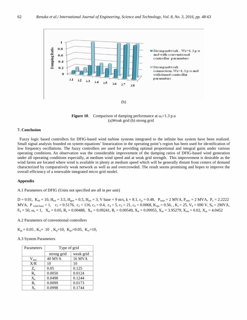
From Figure 10, it can be seen that at high wind speed (ωr=1.3 p.u) there is improvement in damping ratios with tuned controllerparameters. The design of proposed fuzzy logic controllers concentrate more on weak network strength and hence theimprovement in damping ratios is more prominent for weak network strength than for strong network strength.
(a)
Renuka et al./ International Journal of Engineering, Science and Technology, Vol. 8, No. 3, 2016, pp. 48-6362
(b)
Figure 10. Comparison of damping performance at ωr=1.3 p.u(a)Weak grid (b) strong grid
7. Conclusion
Fuzzy logic based controllers for DFIG-based wind turbine systems integrated to the infinite bus system have been realized.Small signal analysis founded on system equations’ linearization in the operating point’s region has been used for identification oflow frequency oscillations. The fuzzy controllers are used for providing optimal proportional and integral gains under variousoperating conditions. An observation was the considerable improvement of the damping ratios of DFIG-based wind generationunder all operating conditions especially, at medium wind speed and at weak grid strength. This improvement is desirable as thewind farms are located where wind is available in plenty at medium speed which will be generally distant from centers of demandcharacterized by comparatively weak network as well as and overcrowded. The result seems promising and hopes to improve theoverall efficiency of a renewable integrated micro grid model.
Appendix
A.1 Parameters of DFIG (Units not specified are all in per unit)
D = 0.01, Ksh = 10, Htot = 3.5, Hgen = 0.5, Htur = 3, V base = 9 m/s, k = 8.1, cp = 0.48, Pnom = 2 MVA, Pmec = 2 MVA, Pe = 2.2222MVA, P wind base = 1, c1 = 0.5176, c2 = 116, c3 = 0.4, c4 = 5, c5 = 21, c6 = 0.0068, Kopt = 0.56, , Ki = 25, Vb = 690 V, Sb = 2MVA,Fb = 50, ωs = 1, Xtr = 0.05, Rs = 0.00488, Xls = 0.09241, Rr = 0.00549, Xlr = 0.09955, Xm = 3.95279, Xrm = 0.02, Xss = 4.0452
A.2 Parameters of conventional controllers
Kpt = 0.05 , Kit= 10 , Kp=10, Kpv=0.05, Kiv=10,
A.3 System Parameters
Type of gridParameters
strong grid weak gridVAsc 40 MVA 16 MVAX/R 10 10Ze 0.05 0.125Re 0.0050 0.0124Xe 0.0498 0.1244Rt 0.0099 0.0173Xt 0.0998 0.1744

Renuka et al./ International Journal of Engineering, Science and Technology, Vol. 8, No. 3, 2016, pp. 48-6363
References
Anaya-Lara O, Jenkins N, Ekanayake JB, Cartwright P, Hughes M. 2009. Wind Energy Generation, Modelling and control.Hoboken, NJ, Wiley.
Cardenas R., Pena R., Alepuz S. and Asher G. 2013. Overview of control systems for the operation of DFIGs in wind energyapplications. IEEE Transactions on Industrial Electronics 60 (2013) 2776–2797.
Chauhan R. K., Rajpurohit B. S. , Hebner R.E., Singh S. N. and Longatt F. M. G. 2016. Design and analysis of PID and fuzzy-PID controller for voltage control of DC microgrid. Smart Grid Technologies - Asia (ISGT ASIA), 2015 IEEE Innovative,Bangkok, Vol. 5, pp. 1-6.
Chatterjee S., Naithani A. and Mukherjee V. 2016. Small-signal stability analysis of DFIG based wind power system usingteaching learning based optimization. International Journal of Electrical Power & Energy Systems, Vol. 78, pp. 672–689.
Elkington K., Knazkins V. and Ghandhari M. 2008. On the stability of power systems containing doubly fed induction generator-based generation. Electrical Power Systems Ressearch, Vol. 78, pp. 1477-1484.
Ekanayake J.B., Holdsworth L., Wu X, and Jenkins N. 2003. Dynamic modelling of doubly fed induction generator wind turbines.IEEE Transactions on Power Systems, Vol. 18, No. 2, pp. 803-809.
Holdsworth L., Wu X.G., Ekanayake J.B., and Jenkins N. 2003. Comparison of fixed-speed and doubly-fed induction windturbines during power system disturbances . IEE Proc Gener. Transm. Distrib., 150(3), pp. 343-352.
Kong S.Y., Bansal R.C., and Dong Z.Y. 2012. Comparative small-signal stability analyses of PMSG-, DFIG and SCIG-basedwind farms. International Journal of Ambient Energy, Vol. 33, No. 2, pp. 87-97.
Kundur P.1994. Power System Stability and Control. The EPRI Power System Engineering Series, New York, McGraw- Hill, Inc.Liao K., He Z., Sun B. and Jia Y. 2013. Small signal stability analysis for a DFIG-based offshore wind farms collected through
VSC-HVDC Transmission. Energy and Power Engineering, Vol. 5, pp. 429-433Mehta B., Bhatt P., and Pandya V. 2014. Small signal stability analysis of power systems with DFIG based wind power
penetration. International Journal of Electrical Power Energy Systems, Vol. 58, pp. 64-74.Mishra Y., Mishra S., Li F., Dong Z.Y. and Bansal R.C.. 2009. Small-signal stability analysis of a DFIG- based wind power
system under different modes of operation. IEEE Transactions on Energy Conversion, Vol.24, No.4, pp. 972-982.Mehta B., Bhatt P. and Pandya V. 2015. Small signal stability enhancement of DFIG based wind power system using optimized
controllers parameters. Electrical Power and Energy Systems, Vol. 70, pp. 70-82.Shawon M.H., Al-Durra A., Caruana C. and Muyeen S.M. 2013. Small signal stability analysis of doubly fed induction generator
including SDBR. Journal of International Conference on Electrical Machines and Systems, Vol.2, No.1, pp.31-39.Sun B., He Z., Jia Y. and Liao K.. 2013. Small-signal stability analysis of wind power system based on DFIG. Energy and Power
Engineering, Vol. 5, pp. 418-422.Tsourakis G. , Nomikos B. M. and Vournas C. D.2009. Effect of wind parks with doubly fed asynchronous generators on small-
signal stability. Electr.Power Syst. Res., Vol. 79, pp. 190-200.Wang C. and. Shi L. 2008. Small signal stability analysis considering grid connected wind farms of DFIG type. Proc. IEEE Power
and Energy Society General Meeting, Jul. 2008, pp. 20-24.Wu F, Zhang X-P, Godfrey K, and Ju P. 2007. Small signal stability analysis and optimal control of a wind turbine with doubly
fed induction generator. IET Generation Transmission and Distribution, Vol. 5, pp. 751-760.Yang L., Ma X. and Dai D.2009. Hopf bifurcation in doubly fed induction generator under vector control. Chaos, Solitons and
Fractals, Vol. 41, No. 5, pp. 2741-2749.Yang L., Østergaard J., Dong Z.Y., Wong K.P., and Ma X. 2011. Oscillatory stability and eigenvalue sensitivity analysis of a
DFIG wind turbine system. IEEE Transactions on Energy Conversion, Vol.26, No.1, pp. 328-339.
Biographical notes
T. K. Renuka received M. Tech. from Government Engineering College, Thrissur, Kerala, India in 2010. She is working as Assistant Professor in the Departmentof Electrical & Electronics Engineering, MES College of Engineering, Kuttippuram, Kerala, India. Presently she is pursuing Ph D (Part Time) at GovernmentEngineering College, Thrissur, Kerala affiliated to University of Calicut, India.
Dr. P. Reji is working as Associate Professor in the Department of Electrical & Electronics Engineering, Government Engineering College, Thrissur, Kerala, India.She received Ph.D from National Institute of Technology Calicut, India. She has more than 20 years of experience in teaching and presently she is guiding severalresearch works.
Dr. Sasidharan Sreedharan received his M.Tech in Electrical Power System from Govt Engineering College, Thrissur, Kerala, India in 1998 and Ph.D fromAsian Institute of Technology, Bangkok, in 2010 respectively. He was post-doctoral research fellow in RED Lab, Renewable Energy Design Laboratory,University of Hawaii, United Stated from 2014-2015. His Research interests are in grid integration of Renewable, AI applications to power systems and gridstability.
Received August 2016Accepted September 2016Final acceptance in revised form October 2016