Embed Size (px)
Citation preview
UNIVERSITI TEKNIKAL MALAYSIA MELAKA
STUDY ON COMPUTER AIDED MANUFACTURING (CAM) SOFTWARE FOR A XY TABLE POSITIONING SYSTEM
This report submitted in accordance with requirement of the Universiti Teknikal
Malaysia Melaka (UTeM) for the Bachelor Degree of Manufacturing Engineering
(Robotic & Automation) with Honours.
By
CHEN PICK WEI
FACULTY OF MANUFACTURING ENGINEERING
2009/2010
** Jika Laporan PSM ini SULIT atau TERHAD, sila lampirkan surat daripada pihak berkuasa/organisasi berkenaan dengan menyatakan sekali sebab dan tempoh laporan PSM ini perlu dikelaskan sebagai SULIT atau TERHAD.
Cop Rasmi: Tarikh: _______________________
Disahkan oleh:
Alamat Tetap: 350, TAMAN SERI INDAH FASA 5, JALAN LENCONG BARAT,______ 05150 ALOR SETAR_____________ KEDAH________________________ Tarikh: _________________________
TAJUK: Study on Computer Aided Manufacturing (CAM) software for a XY table positioning system
SESI PENGAJIAN: 2009/10 Semester 2 Saya CHEN PICK WEI mengaku membenarkan Laporan PSM ini disimpan di Perpustakaan Universiti Teknikal Malaysia Melaka (UTeM) dengan syarat-syarat kegunaan seperti berikut:
1. Laporan PSM adalah hak milik Universiti Teknikal Malaysia Melaka dan penulis. 2. Perpustakaan Universiti Teknikal Malaysia Melaka dibenarkan membuat salinan
untuk tujuan pengajian sahaja dengan izin penulis. 3. Perpustakaan dibenarkan membuat salinan laporan PSM ini sebagai bahan
pertukaran antara institusi pengajian tinggi. 4. **Sila tandakan (√)
UNIVERSITI TEKNIKAL MALAYSIA MELAKA
BORANG PENGESAHAN STATUS LAPORAN PROJEK SARJANA MUDA
SULIT
TERHAD
TIDAK TERHAD
(Mengandungi maklumat yang berdarjah keselamatan atau kepentingan Malaysia yang termaktub di dalam AKTA RAHSIA RASMI 1972) (Mengandungi maklumat TERHAD yang telah ditentukan oleh organisasi/badan di mana penyelidikan dijalankan)

i
DECLARATION
I hereby, declared this report entitled “Study on Computer Aided Manufacturing (CAM)
software for a XY table positioning system” is the results of my own research except as
cited in references.
Signature : ……………………………………………
Author’s name : CHEN PICK WEI
Date : 09 April 2010

ii
APPROVAL
This report is submitted to the Faculty of Manufacturing Engineering of UTeM as a
partial fulfillment of the requirements for the Degree of Bachelor of Manufacturing
Engineering (Robotic and Automation) with Honours. The member of the supervisory
committee is as follow.
..………………………………
Supervisor : Mr. Shariman Bin Abdullah
Date :
Stamp :
iii
ABSTRACT
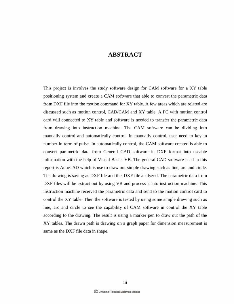
This project is involves the study software design for CAM software for a XY table
positioning system and create a CAM software that able to convert the parametric data
from DXF file into the motion command for XY table. A few areas which are related are
discussed such as motion control, CAD/CAM and XY table. A PC with motion control
card will connected to XY table and software is needed to transfer the parametric data
from drawing into instruction machine. The CAM software can be dividing into
manually control and automatically control. In manually control, user need to key in
number in term of pulse. In automatically control, the CAM software created is able to
convert parametric data from General CAD software in DXF format into useable
information with the help of Visual Basic, VB. The general CAD software used in this
report is AutoCAD which is use to draw out simple drawing such as line, arc and circle.
The drawing is saving as DXF file and this DXF file analyzed. The parametric data from
DXF files will be extract out by using VB and process it into instruction machine. This
instruction machine received the parametric data and send to the motion control card to
control the XY table. Then the software is tested by using some simple drawing such as
line, arc and circle to see the capability of CAM software in control the XY table
according to the drawing. The result is using a marker pen to draw out the path of the
XY tables. The drawn path is drawing on a graph paper for dimension measurement is
same as the DXF file data in shape.

iv
ABSTRAK
Projek ini melibatkan pengajian pada reka bentuk satu perisian CAM bagi mengawal
pergerakkan XY meja dan menciptakan satu perisian CAM yang dapat menukarkan
informasi dari DXF kepada arahan mesin untuk XY meja. Pengawalan gerakan,
“CAD/CAM” dan XY meja akan dibincang. Satu PC dengan kad pengawalan gerakan
akan disambung dengan XY meja dan perisian komputer diperlukan untuk menukarkan
dimensi data dari perisian kepada maklumat berguna menjadi arahan mesin. Perisian
CAM boleh dibahagikan kepada secara tangan dan secara automatik. Cara secara tangan
adalah masukan number secara diri sendiri. Bagi cara secara automatik pula, perisian
CAM dicipta dan menukarkan kepada perisian CAD dalam bentuk DXF dengan
menggunakan VB. Secara umumnya, perisian CAD yang digunakan adalah AutoCAD
untuk melukiskan lukisan yang mudah seperti bulat garisan, lengkungan dan bulat.
Lukisan ini dikehendaki simpan dalam bentuk DXF. Maklumat dari DXF akan
dikeluarkan dengan VB dan diproses menjadi arahan mesin. Arahan mesin ini akan
berkerjasama dengan kad pengawalan gerakan untuk mengerakkan XY meja. Kemudian,
perisian yang dicipta ini akan diuji dengan lukisan mudah untuk menunjukan kebolehan
perisian untuk menukarkan dimensi data dari lukisan kepada arahan mesin untuk XY
meja. Kemudian perisian itu diujikan untk melukis garisan, lengkungan dan bulatan
supaya perisian CAM itu boleh menggerakkan XY meja sama dengan lukisan. Pen
marker diggunakan untuk melukis di atas XY meja. Dimensi yang dapat dilukis di atas
graf adalah sama dengan bentuk data DXF.

v
DEDICATION
This report is dedication to my supervisor, Mr. Shariman Bin Abdullah and not forgotten
to my parents, and to all my friends who have help me in this project.

vi
ACKNOWLEDGEMENT
I would like to take this opportunity to thank my supervisor Mr. Shariman that give a lot
of supports, supervises, encouragement, patience and constructive opinions throughout
this project.
I am grateful for the cooperation and guidance which are given by my friends. First of
all, I really appreciate the kindness of my friends who gave me so much important
information about the project and willing to help me answering my entire question
without hesitation.
Last, I also would like to thank my parents for their support.

vii
TABLE OF CONTENTS
Declaration ..................................................................................................................... i Approval........................................................................................................................ii Abstract ....................................................................................................................... iii Abstrak ......................................................................................................................... iv
Dedication ..................................................................................................................... v
Acknowledgement ........................................................................................................ vi Table Of Contents ........................................................................................................ vii List Of Table ................................................................................................................. x
List Of Figures .............................................................................................................. xi List Of Abbreviations, Symbols, Specialized Nomenclature........................................xiii
CHAPTER 1 .................................................................................................................. 1
INTRODUCTION ..................................................................................................... 1
1.1 Introduction ................................................................................................ 1
1.2 Objective .................................................................................................... 2
1.3 Problem Statement ..................................................................................... 2
1.4 Scope ......................................................................................................... 2
1.5 Gantt chart .................................................................................................. 3 CHAPTER 2 .................................................................................................................. 4
LITERATURE REVIEW ........................................................................................... 4
2.1 Introduction ................................................................................................ 4
2.2 Computer Aided Design (CAD) .................................................................. 4
2.3 Computer Aided Manufacturing (CAM) ..................................................... 6
2.4 Computer-Aided Design and Manufacturing (CAD/CAM) ......................... 7
2.4.1 CAD/ CAM Approach .......................................................................... 8
2.4.2 Application CAD/CAM System for Deep Drawing Dies ....................... 9
2.4.3 CAD/CAM System for Tool Elements ................................................ 10
2.5 Numerical Control (NC) ........................................................................... 12
2.5.1 Step-NC Code to Be Generated ........................................................... 13
2.6 Motion Control ......................................................................................... 14
2.6.1 Introduction to Motion Control ........................................................... 14
viii
2.7 Motion Controller ..................................................................................... 16
2.7.1 Functions of a Motion Controller ........................................................ 16
2.7.2 Types of Motion Controller ................................................................. 17
2.7.3 Application for Motion Controller ....................................................... 20
2.7.3.1 Motion Controller for Construction Machinery ............................... 20
2.8 XY Table.................................................................................................. 21
2.8.1 XY Table with Non-rigid Ballscrew .................................................... 21 CHAPTER 3 ................................................................................................................ 22
METHODOLOGY .................................................................................................. 22
3.1 Flow Chart for the Whole Project ............................................................. 22
3.2 AutoCAD ................................................................................................. 24
3.2.1 Drawing Objects ................................................................................. 24
3.2.2 Lines ................................................................................................... 25
3.2.3 The Line Command ............................................................................ 25
3.2.4 The Rectangle Command .................................................................... 26
3.2.5 The Polygon Command ....................................................................... 27
3.26 The Circle Command .......................................................................... 28
3.2.7 The Arc Command .............................................................................. 29
Figure 3.9: Arc ......................................................................................... 29
3.3 AutoCAD DXF ...................................................................................... 29
3.3.1 DXF format of the drawing file ....................................................... 31
3.3.2 Automatic Generation of Graphic Entities ....................................... 32
3.3.3 Generation of Drawings Composed Of Several Entities ................... 33
3.4 Visual Basic ............................................................................................. 35
3.4.1 Creating First Application ................................................................... 35
3.4.2 Using If.....Then.....Else Statements with Operators .......................... 36
3.4.3 Select Case....End select Control Structure .......................................... 37
3.5 Graphical User Interface (GUI) ................................................................ 39
3.6 Motion Command..................................................................................... 40
3.6.1 2 Axes Linear Interpolation ................................................................. 41
3.7 Extract Data.............................................................................................. 44
3.8 Process Data ............................................................................................. 47
3.8.1 Declaration ......................................................................................... 47
3.8.2 Calculation for Line ............................................................................ 48
ix
3.8.3 Calculation for Arc ............................................................................. 48
3.8.4 Calculation for Circle .......................................................................... 50
3.9 Instruction Machine .................................................................................. 51
3.10 Testing Software ...................................................................................... 51
3.11 Result ....................................................................................................... 51 CHAPTER 4 ................................................................................................................ 52
RESULT .................................................................................................................. 52
4.1 Graphical User Interface (GUI) ................................................................ 52
4.2 Measurement Drawing.............................................................................. 58
4.2.1 Circle .................................................................................................. 58
4.2.2 Line .................................................................................................... 59
4.2.3 Triangle .............................................................................................. 60
4.2.4 Arc ...................................................................................................... 61
4.2.5 Arc Different Angle ............................................................................ 62
4.3 Flow Chart for the program ...................................................................... 64 CHAPTER 5 ................................................................................................................ 65
DISCUSSION .......................................................................................................... 65 CHAPTER 6 ................................................................................................................ 66
CONCLUSION ....................................................................................................... 66 CHAPTER 7 ................................................................................................................ 68
FUTURE WORK..................................................................................................... 68 REFERENCES ............................................................................................................ 69 APPENDIX ................................................................................................................. 71

x
LIST OF TABLES
Table 3.1: Arithmetic Operator .................................................................................... 50
xi
LIST OF FIGURES
1.1 The position of CAM Software in the process 1
1.2 Gantt chart PSM I and PSM II 3
2.1 Block diagram of the CAD/CAM system for deep drawing dies 11
2.2 Operator-controlled and numerically controlled machine tools 12
2.3 STEP-NC part program 13
2.4 Constitution of a typical motion control system 15
2.5 Motion Controller Architecture 17
2.6 Computer Standard Bus Based Motion Controller 18
2.7 Embedded Motion Controller 19
2.8 Table Positioning System 21
3.1 The Flow of Process in Whole Project 23
3.2 Toolbar of AutoCAD 24
3.3 Draw Toolbar 24
3.4 Straight Line 26
3.5 Rectangle 26
3.6 Polygon 27
3.7 Circle 28
3.8 3P and 2P option 28
3.9 Arc 29
3.10 Parametric Representation of the Rectangle 31
3.11 Representation of particular cases of a Rectangle 31
3.12 Excerpt from the DXF file of a rectangle 32
3.13 Structure of DXF data of Line and Arc entities 33
3.14 Instructions for writing data for LINE and ARC elements 34
3.15 Drawing consisting of three elements 34
3.16 Structure of DXF data for a sequence of entities 35
xii
3.17 Source Code Window 36
3.18 General Format of if..then..else Statement 37
3.19 Example of if..then..else Statement 37
3.20 General Format of the Select Case Control Structure 38
3.21 Example of the Select Case Control Structure 39
3.22 Graphical User Interface 40
3.23 Example of Program 41
3.24 2 Axis Linear Interpolation 42
3.25 The Speed Ratio 42
3.26 Location of DXF file is allocated 44
3.27 DXF file is selected 44
3.28 Command used in Search related information 45
3.29 Transferring parametric data into Array 45
3.30 The Parametric Data from DXF file 46
3.31 Drawing shown in Picture Box 46
3.32 Declaration of Variable used in Program 47
3.33 Method used in calculate Line 48
3.34 Method to Convert Degree to Radian 48
3.35 Method to calculate Arc 49
3.36 Method to calculate Circle 50
4.1 Graphical User Interface (GUI) 52
4.2 Result for Circle Drawing 58
4.3 Result for Line Drawing 59
4.4 Result for Triangle Drawing 60
4.5 Result for Arc Drawing 61
4.6 Result for Arc Different Angle Drawing 62
4.7 Program Flow Chart 63
xiii
LIST OF ABBREVIATIONS
CAD - Computer Aided Design
CAM - Computer Aided Manufacturing
CAE - Computer Aided Engineering
CNC - Computer Numerical Control
CPU - Computer Power User
DXF - Drawing Exchange File
EMC - Embedded Motion Controller
ISA - Industry Standard Architecture
NC - Numerical Control
PC - Personal Computer
PCI - Peripheral Component Interconnect
PLC - Programmable Logic Controller
UPL - User Programming Language
USB - Universal Serial Bus
VME - Versa Module Europa
1
CHAPTER 1 INTRODUCTION
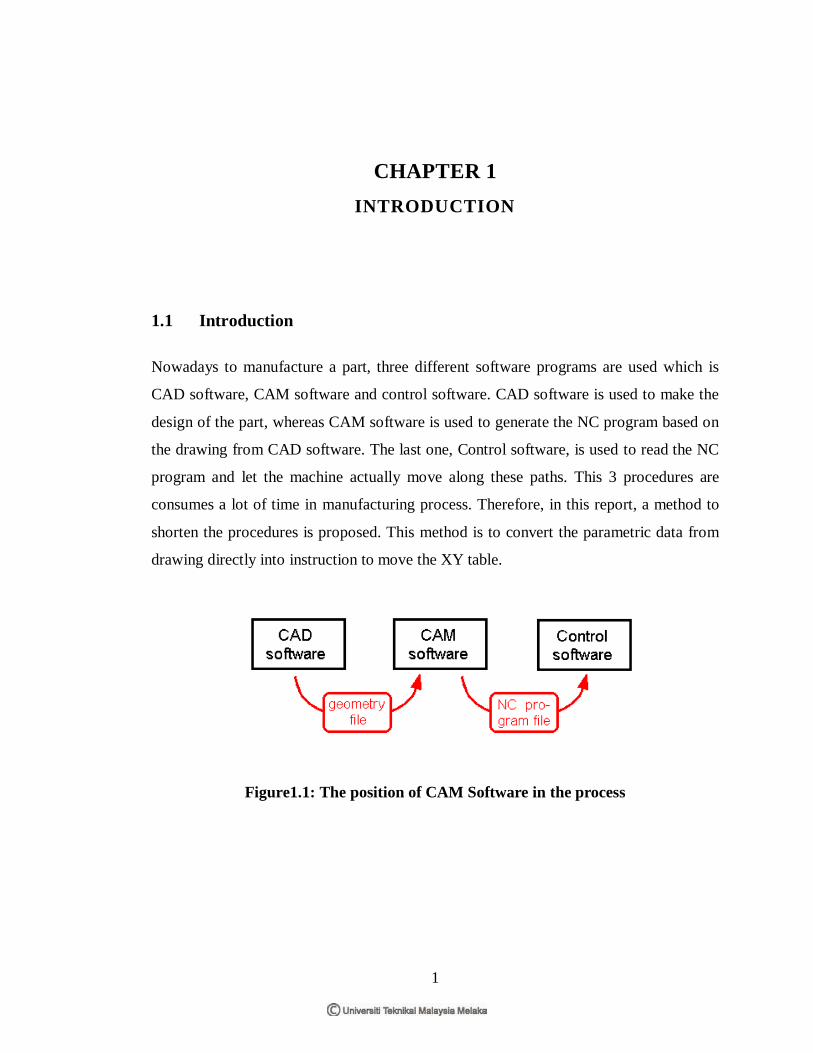
1.1 Introduction
Nowadays to manufacture a part, three different software programs are used which is
CAD software, CAM software and control software. CAD software is used to make the
design of the part, whereas CAM software is used to generate the NC program based on
the drawing from CAD software. The last one, Control software, is used to read the NC
program and let the machine actually move along these paths. This 3 procedures are
consumes a lot of time in manufacturing process. Therefore, in this report, a method to
shorten the procedures is proposed. This method is to convert the parametric data from
drawing directly into instruction to move the XY table.
Figure1.1: The position of CAM Software in the process
2
1.2 Objective
The objectives of this project are:
• To create software can convert CAD data to command for control XY table.
• To create a graphical user interfaces to easy use the software.
1.3 Problem Statement
Nowadays, in order to convert parametric data from drawing to instruction for machine,
CAM software is require converting the parametric data from drawing into NC
program file. This NC program file will later convert by control software of machine
into the instruction for machine such as XY table. All these procedures take times to
accomplish and are consider as a waste. Other than that, it is also troublesome and
inconvenient to use different software in converting a drawing into instruction for
machine.
1.4 Scope
This project is involves the software design for CAM software for a XY table
positioning system. In this project, the CAM software converts the parametric data from
CAD software. The CAD data is in the form of AUTOCAD DXF files whereas includes
CAD drawing parametric data. Other than that, CAD data convert the instruction data
such as line, circle and arc in the 2D data to motion controller card for move the XY
table positioning system to a position based on the CAD software. It is also to
understand the application of Visual Basic.
3
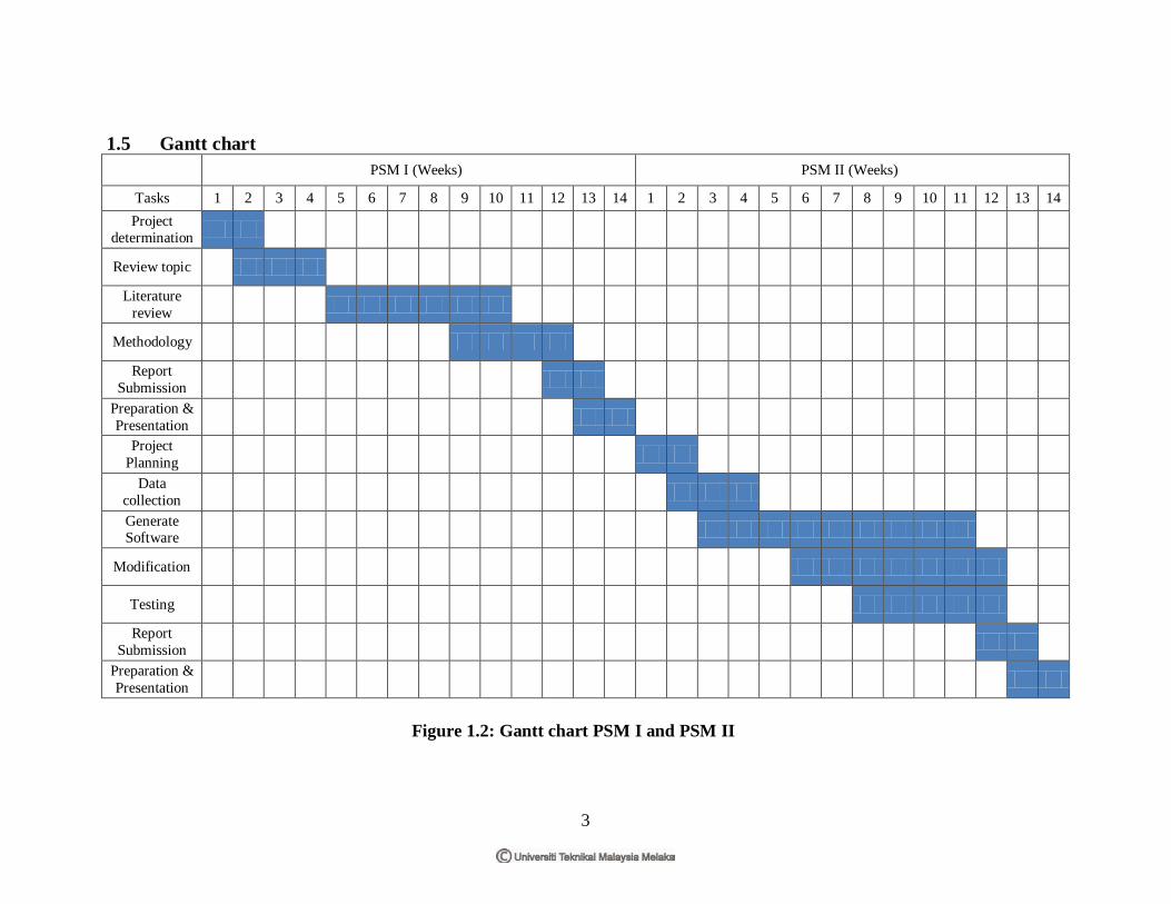
1.5 Gantt chart PSM I (Weeks) PSM II (Weeks)
Tasks 1 2 3 4 5 6 7 8 9 10 11 12 13 14 1 2 3 4 5 6 7 8 9 10 11 12 13 14 Project
determination
Review topic
Literature review
Methodology
Report Submission
Preparation & Presentation
Project Planning
Data collection
Generate Software
Modification
Testing
Report Submission
Preparation & Presentation
Figure 1.2: Gantt chart PSM I and PSM II

4
CHAPTER 2 LITERATURE REVIEW
2.1 Introduction
This project involves the study software design for CAM software for a XY table
positioning system. The CAM software will convert parametric data from General CAD
software to move the XY table by using the motion controller card. So, in this section
there are some field involving in this project such as CAD/CAM, motion controller and
XY table.
2.2 Computer Aided Design (CAD)
Computer Aided Design (CAD) is the technology concerned with the use of computer
systems to assist in the creation, modification, analysis, and optimization of a design.
The basic function of CAD is to define the geometry of design, such as a mechanical
part, a product assembly, an architectural structure, an electronic circuit and a building
layout.
An engineer would prepare a blueprint manually for the total product, including the
tooling to produce the product. Other than that, other engineers would provide the
drawings for their specialized area. These would be used throughout the product
development process and updated or changed as the process continued. This process was
very expensive in terms of time and money. CAD has improved the process a lot and
reduced dramatically the development costs and time. [Ed. Richard C. Dorf, 2000]

5
CAD allows different layers to be created, which is allows other software to take the
part geometry from each layer and assign different tools to machine it. Furthermore, the
computer also allows design to be viewed and tested before manufacturing. CAD
systems stress-test parts to meet the strength requirements of the application. Graphics
capabilities allow three-dimensional (3D) viewing of parts from any angle. The CAD
systems also can export the CAD part file in Drawing Exchange File (DXF) format. The
following is some advantages of using the CAD system. [Helmi A. Youssef, 2008]
i. Increase the productivity of the designers
ii. Create better designs
iii. Reduced design timescales
iv. Reduce redundant effort
v. Reuse of designs
vi. Allow easy and rapid modification of prints
vii. Drawing errors can be corrected easily.
6
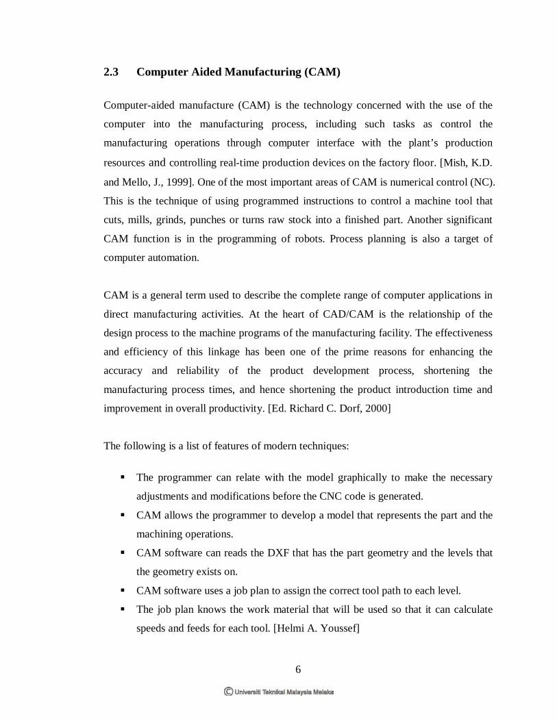
2.3 Computer Aided Manufacturing (CAM) Computer-aided manufacture (CAM) is the technology concerned with the use of the
computer into the manufacturing process, including such tasks as control the
manufacturing operations through computer interface with the plant’s production
resources and controlling real-time production devices on the factory floor. [Mish, K.D.
and Mello, J., 1999]. One of the most important areas of CAM is numerical control (NC).
This is the technique of using programmed instructions to control a machine tool that
cuts, mills, grinds, punches or turns raw stock into a finished part. Another significant
CAM function is in the programming of robots. Process planning is also a target of
computer automation.
CAM is a general term used to describe the complete range of computer applications in
direct manufacturing activities. At the heart of CAD/CAM is the relationship of the
design process to the machine programs of the manufacturing facility. The effectiveness
and efficiency of this linkage has been one of the prime reasons for enhancing the
accuracy and reliability of the product development process, shortening the
manufacturing process times, and hence shortening the product introduction time and
improvement in overall productivity. [Ed. Richard C. Dorf, 2000]
The following is a list of features of modern techniques:
The programmer can relate with the model graphically to make the necessary
adjustments and modifications before the CNC code is generated.
CAM allows the programmer to develop a model that represents the part and the
machining operations.
CAM software can reads the DXF that has the part geometry and the levels that
the geometry exists on.
CAM software uses a job plan to assign the correct tool path to each level.
The job plan knows the work material that will be used so that it can calculate
speeds and feeds for each tool. [Helmi A. Youssef]
7
2.4 Computer-Aided Design and Manufacturing (CAD/CAM)
The development of CAD/ CAM systems started in 1950s. A computer MIT was first
used to generate simple pictures on a Cathode Ray Tube (CRT) display. During late
1950s the Automatically Programmed Tools (APT) was developed and General Motors
began to explore the potential of interactive graphics. 1960s was the most critical
research period for interactive computer graphics. As computer graphics become more
developed, CAD began to establish as a technique when computer graphics was used in
the design process. [Y C Kao* and G C I Lin*, 1996]
In the early 1970s, CAD systems with drafting and modeling capabilities become
available. The new capabilities such as Finite Element, Analysis, and NC milling and
Turning were added to these systems to help productivity. In the 1980s, CAD/CAM
research took place, and new CAD/CAM systems the various elements of design and
manufacturing. Then, the CAD/CAM system is including more applications such as
mechanism and robotics analysis, and injection molding design and analysis. In the
1990s, when the new manufacturing algorithms and capabilities are developed, the
CAD/CAM technology will become more mature. The faster computer hardware such as
PC and workstation also are available.
Computer-aided design (CAD) and manufacturing (CAM) are defined by the use of
computer software and hardware to assist in the manufacturing process. Inasmuch as the
software is used to “drive” the production machinery in CAM, CAD is the use of
software and hardware to assist in the design process.
CAM is a simply of the computer’s use in the context of the manufacturing process.
According to the Automation Encyclopaedia, CAM involves many different activities,
including on-line planning, tool design and production, computer-numerical control
(CNC), automated assembly, computer-aided process planning, scheduling, automated
materials handling, and robotics. [Ed. Richard C. Dorf , 2000]
8
2.4.1 CAD/ CAM Approach
The integrated CAD/CAM approach prepares the part program directly from the CAD
part geometry by using NC programming commands. Other than that, the CAD/CAM
system also can by passing the CAD geometry into a dedicated CAM program. The
CAD drawings can be changed to CNC programs by using CAD/CAM systems. The
CAD/CAM approach has the following advantages: [Helmi A. Youssef, 2008]
i. Do not need to encode the part geometry and the tool motion
ii. Allows the use of interactive graphics for program editing and verification
iii. Displays the programmed motions of the cutter and allows visual verification of
the program
iv. Allows interactive editing of the tool path with the addition of the tool moves
and standard cycles
v. Includes the most sophisticated algorithms for part programming generation
The programming steps for CAD/CAM approach are as follows: [Helmi A. Youssef,
2008]
1. The aspects of the part geometry that are important for machining purposes are
identified; geometry may be edited or additional geometry added to define
boundaries for the tool motion.
2. Tool geometry is defined; for instance, by selecting tools from a library.
3. The desired sequence of machining operations is identified and tool paths are
defined interactively for the main machining operations.
4. The tool motion is displayed and may be edited to refine the tool motion, or other
details may be added for particular machining cycles or operations.
5. A CLDATA file is produced from the edited tool paths.
6. The CLDATA file is post processed to MCD, which is then transmitted to the
machine.
9
2.4.2 Application CAD/CAM System for Deep Drawing Dies In the middle of the methods of sheet metal forming, deep drawing is that most
commonly used. However, the traditional process design of deep drawing is performed
by human experts with their empirical knowledge. In recent years, some computer-aided
process and die design systems based on the empirical knowledge of the field experts
have been developed for axisymmetric deep drawing products. Tisza’s work describes a
modular CAD/CAM system, in process, for developing deep drawing process sequences
and designing tools for the manufacture of sheet-metal components having
axisymmetric and rectangular cross-sections [M. Tisza, 1987]. Furthermore, Sitaraman
et al. developed a hybrid computer-aided engineering (CAE) system for automatic
process sequence design for the manufacture of axisymmetric sheet-metal components.
[S.K. Sitaraman et al, 1991]
At here, a CAD/CAM system for axisymmetric deep drawing processes has been
developed. The inputs of the CAD/CAM system are the results of Pro–Deep [S.B. Park
et al, 1998]. The system, Pro–Deep, is the process design of a deep drawing system for
axisymmetric products [E. Doege et al, 1998]. A knowledge based approach is
employed for the system. Under the environment of CAD/CAM software of Personal
Designer, the system has been written in User Programming Language (UPL). The part
drawings of die sets for each process are generated in the tool design module of the
CAD/CAM system. Besides that, the die assembly drawings can be obtained. NC
commands for the machining of the part can be generated in the developed CAD/CAM
system. Other than that, the system can be applied to a blanking die set and deep
drawing in a simple-action press.