Embed Size (px)
Citation preview

This report submitted in accordance with requirement of the Universiti
Teknikal Malaysia Melaka (UTeM) for the Bachelor Degree of Manufacturing
Engineering
(Manufacturing Process) (Hons.)
By
HANIF BIN ASHA’RI
B051010175
890924-01-5577
FACULTY OF MANUFACTURING ENGINEERING
2013
UNIVERSITI TEKNIKAL MALAYSIA MELAKA
DESIGN AND MACHINING OF AEROSPACE COMPONENT

UNIVERSITI TEKNIKAL MALAYSIA MELAKA
BORANG PENGESAHAN STATUS LAPORAN PROJEK SARJANA MUDA
TAJUK: Design and Machining of Aerospace Component
SESI PENGAJIAN: 2012/13 Semester 2 Saya HANIF BIN ASHA’RI mengaku membenarkan Laporan PSM ini disimpan di Perpustakaan Universiti Teknikal Malaysia Melaka (UTeM) dengan syarat-syarat kegunaan seperti berikut:
1. Laporan PSM adalah hak milik Universiti Teknikal Malaysia Melaka dan penulis. 2. Perpustakaan Universiti Teknikal Malaysia Melaka dibenarkan membuat salinan
untuk tujuan pengajian sahaja dengan izin penulis. 3. Perpustakaan dibenarkan membuat salinan laporan PSM ini sebagai bahan
pertukaran antara institusi pengajian tinggi.
4. **Sila tandakan ( )
SULIT
TERHAD
TIDAK TERHAD
(Mengandungi maklumat yang berdarjah keselamatan atau kepentingan Malaysia sebagaimana yang termaktub dalam AKTA RAHSIA RASMI 1972)
(Mengandungi maklumat TERHAD yang telah ditentukan oleh organisasi/badan di mana penyelidikan dijalankan)
Alamat Tetap:
Pos 207, Kg Seri Menanti,
Jln Muar – Bt Pahat, 84160, Pt Jawa,
Muar, Johor.
Tarikh: ________________________
Disahkan oleh:
Cop Rasmi: Tarikh: _______________________
** Jika Laporan PSM ini SULIT atau TERHAD, sila lampirkan surat daripada pihak berkuasa/organisasi berkenaan dengan menyatakan sekali sebab dan tempoh laporan PSM ini perlu dikelaskan sebagai SULIT atau TERHAD.

DECLARATION
I hereby, declared this report entitled “Design and Machining of Aerospace
Component” is the results of my own research except as cited in references.
Signature : ………………………………
Author’s Name : Hanif bin Asha’ri
Date : 21/ 5/ 2013

APPROVAL
This report is submitted to the Faculty of Manufacturing Engineering of UTeM as
a partial fulfillment of the requirements for the degree of Bachelor of
Manufacturing Engineering (Manufacturing Process) (Hons.). The members of
the supervisory isas follow:
………………………………
(Project Supervisor)

i
ABSTRACT
This final year project entitled “Design and Machining of Aerospace Component”.
The project is to improve the surface finish of machining from the aerospace
component by getting the optimum cutting parameters. The component is fitting
hinge of landing gear door which is used to join the landing gear door with strut on
the aircraft. This problem is carried out based on the highlighted problems of aircraft
component manufacturer by IMAI AEROSPACE COMPONENT (IAC)
MALAYSIA. The problem occurred on the surface finish of the fitting hinge is
rough surface finish. These problems occurred due to the unsuitable cutting
parameters. To solve the problems, cutting parameter need to be improve. An
experiment was conducted to study the effect of cutting parameter on the surface
finish of the product. Surface roughness, surface integrity and material removal rate
(MRR) was measured for machining performance evaluation. Based on the result, the
significant finding of this study is the surface roughness more influenced by feed rate
and cutting speed. These parameters play a very important role on forming surface
roughness because surface roughness = 0.19µm can be improved when increase the
spindle speed = 3250 rpm and reduce the feed rate = 1000mm/min.
ii
ABSTRAK
Projek tahun akhir ini bertajuk “Design and Machining of Aerospace Component”.
Projek ini adalah untuk penambahbaikkan kemasan permukaan pemesinan pada
komponen aeroangkasa dengan membuat penambah baikkan pada parameter
pemotongan. Komponen tersebut adalah “fitting hinge” yang digunakan pada pintu
roda pendaratan dimana ia digunakan untuk menyambungkan pintu roda pendaratan
dengan topang pada pesawat. Masalah ini didapati daripada masalah yang
diketengahkan oleh IMAI AEROSPACE COMPONENT (IAC) MALAYSIA.
Masalah yang berlaku pada kemasan permukaan “fitting hinge” kemasan permukaan
yang kasar. Masalah ini berlaku kerana parameter pemotongan yang tidak
sesuai.Untuk mengatasi masalah tersebut, parameter pemotongan memerlukan
penambahbaikkan. Eksperiment telah dijalankan untuk mengkaji kesan parameter
pemotongan terhadap kemasan permukaan pada produk. Kekasaran permukaan,
integrity permukaan dan kadar pembuangan bahan (MRR) telah diukur untuk
penilaian prestasi pemesinan. Berdasarkan keputusan yang diperolehi, penemuan
yang ketara dalam kajian ini adalah kekasaran permukaan adalah lebih berhubung
kait dengan kelajuan spindal (spindle speed) dan kadar suapan (feed rate). Parameter
tersebut memainkan peranan yang sangat penting dalam penghasilan kekasaran
permukaan = 0.19µm kerana ia boleh diperbaiki dengan menambah kelajuan
spindal= 3250rpm serta mengurangkan kadar suapan = 1000mm/min.

iii
DEDICATION
Very thankful to Allah and special thanks to my beloved supervisor,
my friends, and
my beloved parent and family
iv
ACKNOWLEDGEMENT
First of all, thanks to my bachelor degree final year project supervisor, Dato’ Prof Dr.
Abu bin Abdullah for his guide, help and support toward this project. With his
advice, this project can be completed according to the plan.
Special thanks to Imai Aerospace Component (IAC) Malaysia that guide me with
technical advice during do this project. Thanks also to my family and friends for their
moral support and some advice, financial support, share the knowledge and idea to
finish this project.
Last but not least, thanks to everyone that involved in this project

v
TABLE OF CONTENT
Abstract i
Abstrak ii
Dedication iii
Acknowledgement iv
Table of Content v
List of Tables viii
List of Figures ix
CHAPTER 1: INTRODUCTION 1
1.1 Background 1
1.2 Problem Statement 2
1.3 Objectives 4
1.4 Scope 4
CHAPTER 2: LITERITURE REVIEW 5
2.1 Aircraft Structural Component 5
2.1.1 Wings 6
2.1.2 Fuselage 7
2.1.3 Empennage 8
2.1.4 Power Plant 9
2.1.5 Landing Gear 10
2.2 Fitting Hinge 11
2.3 Computer-Aided Design/ Computer-Aided Manufacture (CAD/CAM) 14
2.4 Machining 16
2.5 Machining Centre 17
vi
2.6 Milling 19
2.7 Cutting Parameter 20
2.8 Milling Cutter Path Strategies 24
2.9 Consideration in Machining Aluminium 25
2.10 Surface roughness 25
2.11 Material removal rate (MRR) 27
2.12 Surface integrity 28
CHAPTER 3: METHODOLOGY 30
3.1 Introduction 30
3.2 Project flow chart 31
3.3 Project approaches 33
3.3.1 Planning 33
3.3.2 Analysing 33
3.3.2.1 Material 34
3.3.2.2 Machining parameter 35
3.3.3 Designing 37
3.3.3.1 Step in solid modeling generation 37
3.3.3.2 Detail drawing and dimension 39
3.3.4 Machining 40
3.3.4.1 Drawing plane 41
3.3.4.2 Define machine: CNC milling 5-axis 42
3.3.4.3 Define axis 43
3.3.4.4 Define tool: Endmill 12 mm diameter 43
3.3.4.5 Define tool path 44
3.3.4.6 Generate NC code 45
3.3.4.7 Step on CNC machine 46
3.3.5 Surface analysis 46
3.3.5.1 Surface roughness 46
3.3.5.2 Surface integrity 47
vii
CHAPTER 4: RESULTS AND DISCUSSIONS 48
4.1 Surface roughness 49
4.1.1 Result of surface roughness 49
4.1.2 Discussion on surface roughness 52
4.2 Material Removal Rate data 53
4.2.1 Material Removal Rate data 53
4.2.2 Material Removal Rate discussion 54
4.3 Surface integrity 56
4.3.1 Optical micrograph 56
4.3.2 Discussion on optical micrograph 57
CHAPTER 5: CONCLUSION AND RECOMMENDATIONS 58
5.1 Conclusion 58
5.2 Recommendations 59
REFERENCES 60
APPENDICES

viii
LIST OF TABLES
2.1 Monocoque Fuselage and Semi-monocoque construction 8
2.2 Recommended Cutting Speed and Feeds for HSS Milling Cutter
on Aluminium 29
3.1 Aluminium alloy 7050 properties 34
3.2 Machining parameter used for HSS tool in IAC 36
3.3 Machining parameter used for the experiment by carbide tool 36
3.4 DMF 500 linear five-axis machine specifications 41
3.5 Mitutoyo SJ-402 Surftest Portable Surface Roughness
Tester Specifications 47
4.1 Machined surface roughness for HSS cutting tool 48
4.2 Experimental value of surface roughness on machined surface for
carbide cutting tool 49
4.3 Cutting conditions for different spindle speed and feed rate 53
ix
LIST OF FIGURES
1.1 Aircraft fleet growth 2010-2030 3
2.1 Part of an aiplane 5
2.1 Wing Components 7
2.3 The Warren Truss 7
2.4 Empennage Structure 9
2.5 Aircraft Engine
10
2.6 Landing Gear 11
2.7 Position of Nose Landing Gear and Main Landing Gear 12
2.8 Main Landing Gear 13
2.9 Nose Landing Gear 13
2.10 Gear Door’s Hinge 14
2.11 Design Process 15
2.12 Steps in CAM activity 15
2.13 Machining Centre 18
2.14a Peripheral milling 20
2.14b Face milling 20
2.15 A Frame Work For Simulation and Optimization of CNC Machining 22
2.16 An Influence Diagram for Determining Machining Parameter 22
2.17a Milling Cutter Path Strategies : Offset 24
2.17b Milling Cutter Path Strategies: Raster 24
2.17c Milling Cutter Path Strategies: Single-direction raster 24
2.18 The variation of surface roughness, Ra, between feed rate and
tool diameter 26
2.19 The Ra value and figure of surface roughness effect on
spindle speed 27
2.20a Fine Surface 29
2.20b Rough Surface 29

x
3.1 Process Flow Chart for Project Research 31
3.2 Process Flow Chart for Fitting Hinge Manufacturing 32
3.3 Aluminium Alloy 7050 35
3.4 Sketched part 38
3.5 Extrude the part 38
3.6 Detail drawing and dimension 39
3.7 Solid modeling drawing 39
3.8 DMF 500 linear five-axis machine 40
3.9 Create planes 41
3.10 Define the CNC milling machine 42
3.11 Define axis 43
3.12 Define tool 43
3.13 Define toolpath 44
3.14a Tool diameter ratio 44
3.14b Number of level 44
3.15a Define input, output and NC data type 45
3.15b Define machine, format and execute 45
3.16 Mitutoyo SJ-402 Surftest Portable Surface Roughness Tester 46
3.17 Stereo digital imaging 47
4.1 Different surface roughness on different parameters 50
4.2 Surface roughness, Ra (µm) versus Spindle speed, N (RPM) 51
4.3 Surface roughness, Ra (µm) versus Feed rate, v (mm/min) 51
4.4 HSS surface roughness versus Carbide tool surface 51
4.5 MRR for different machining parameters 55
4.6 Machined with spindle speed = 3250 rpm, feed rate =
1000 mm/min, with surface roughness = 0.19 µm 56
4.7 Machined with spindle speed = 2500 rpm, feed rate = 700 mm/min,
with surface roughness = 0.38 µm 56

1
1.1 Background
Manufacturing is concerned with making product. It is combination of processes to
produce object that consist of numerous individual pieces. Manufactured product is
also can be used to make other product like a drill is used for producing holes. There
are two types of product such as discrete product and continuous product. Discrete
product is an individual product such as bolts, nuts, and paper clips. Then,
continuous product is a product which is cut into individual pieces for other process
to create new product.
Manufactured item is start with raw material and following to the sequence of
process to make a single product. Each new form of the material takes on gives it
more use which is utility. The step of changing the form of material is done by a
series of act called process. There are two major types of manufacturing process
which are primary process and secondary process. Primary processing is the process
to changes raw material into standard industrial stock. Raw material can be mineral
ores, hydrocarbon liquid, plants, animal, or any of a number of basic material inputs.
These raw materials are subjected to various primary processing activities.
All the output of primary processing is called industrial standard stock and it is
needed to be further changes in form to be useful which is in the secondary
processing. For secondary processing, it is a form of utility activity. It changes
INTRODUCTION
CHAPTER 1
2
standard stock into useful finished products. The standard stock may be one of the
basic major types of materials which are metals, polymers, or ceramic. After that,
these materials are changed in shape, appearance, and internal properties through six
types of secondary processing which are casting, forming, separating, conditioning,
assembling and finishing. In addition, each of the six secondary process families is
different and they have their own common elements to contribute in their own way to
the form utility of the material.
In the aerospace industries, there are produce many part or aircraft. It is consist of
fuselage, wings, flaps, ailerons, tail, engines and others. To design an aircraft, the
important thing is find the optimal proportion of the weight of the aircraft and
payload. Each component of the aircraft must be strong and stiff enough to withstand
to the variety of situation which it has to operate.
Based on the project title is “Design and Machining of Aerospace Component (fitting
hinge for landing gear door)”. Fitting hinge for landing gear door is a component
that used to join the landing gear door with the strut. Strut will connect to the
hydraulic systems to pull up the fitting hinge and the same time will pull up the
landing gear door too. Fitting hinge is important because it is hold the landing gear
door. It is must be high strength to hold the heavy landing gear door to avoid the
landing gear door drop to the ground. It is also influence to the smooth operation of
the extent and retracts the landing gear door.
1.2 Problem Statement
Today the global aircraft traffic growth level is continuously growing fast in global
scale. The expected number of airplanes in the world will increase at an average of
3.6 % per year by referring to the Figure 1.1 that can shows the estimation number of
the aircraft in the world.

3
Figure 1.1: Aircraft fleet growth 2010-2030 (Gregor Kappmeyer, 2012)
Because of the increasing number of the aircraft, it will influence to the increasing of
number of new components and spare part demands. In order to the current and
future demands, the manufacturing sector had built up and developed more global
supply chain to cope with the production numbers and quality standards to make sure
the best deliveries of demands in the industry.
The machining of the aerospace component material is focused on the high stock
removal rates in roughing processes and also in the high surface finishing rates and
good surface finish and surface integrity in finish machining. The common problems
that occur on the machined part surface are vibration mark, mismatch and over
cutting. There are many factors that cause these entire problems happen such as the
cutting parameters is not suitable for the machining process, cutter wear and also
toolpath design.
In the other hands, future business requirements are considered. It is include on
robustness of machining solutions and control of boundary conditions to be met and
acceptable surface condition in machining. The key to achieve the overall quality and
productivity goal is by using modern machine tool concepts, advance machining
processes and methods.

4
1.3 Objectives
The aims of this project are:
1. To study the surface roughness of fitting hinge by changes the machining
parameters.
a) Spindle speed
b) Feed rate
2. To study the surface integrity of high and low surface roughness after
machined by different machining parameters.
3. To find the optimum machining parameters for the accepted surface
roughness from 0 to 0.5 µm.
1.4 Scope
This project focused on the improving the surface finish of part by modification on
the machining parameters in machining process by using CNC vertical machining
centre. Machining parameters are including of feed rate, and spindle seed. The
different surface roughness values will give different surface integrity. The surface
roughness value is in the range of 0 to 0.5 µm for the accepted value of surface
roughness.
5
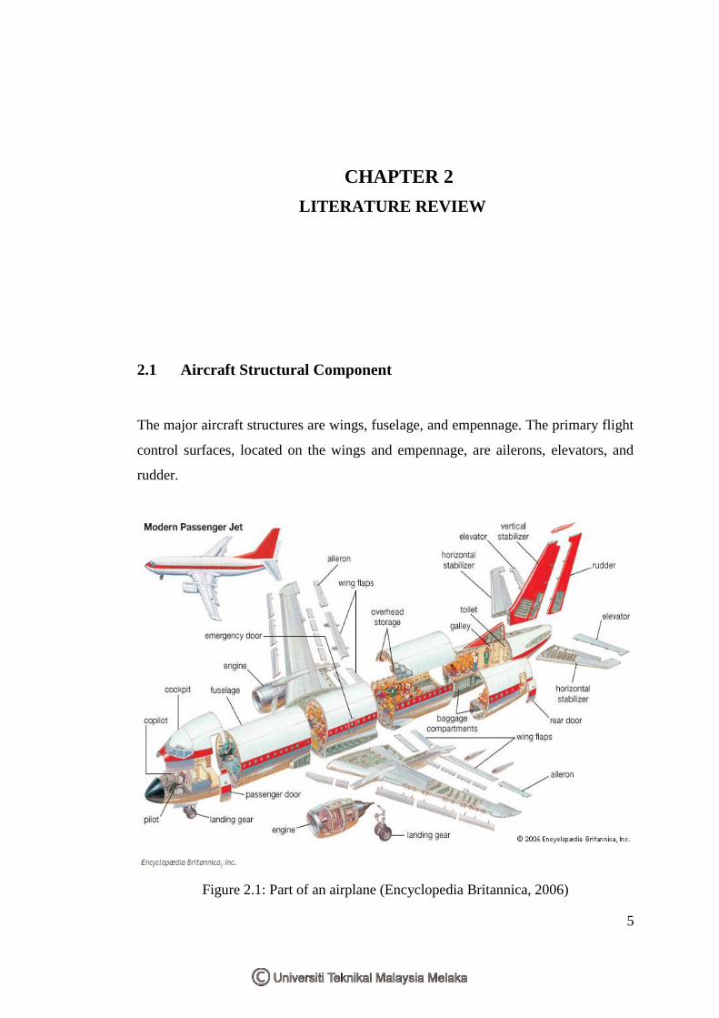
2.1 Aircraft Structural Component
The major aircraft structures are wings, fuselage, and empennage. The primary flight
control surfaces, located on the wings and empennage, are ailerons, elevators, and
rudder.
Figure 2.1: Part of an airplane (Encyclopedia Britannica, 2006)
LITERATURE REVIEW
CHAPTER 2
6
2.1.1 Wings
Aircraft wings have to be strong enough to withstand the positive forces of flight as
well as the negative forces of landing. Metal wings are of two types: Semicantilever
and full cantilever. Semicantilever, or braced, wings are used on light aircraft. They
are externally supported by struts or flying wires which connect the wing spar to the
fuselage. A full cantilever wing is usually made of stronger metal. It requires no
external bracing or support. The skin carries part of the wing stress. Parts common to
both wing designs are spars, compression ribs, former ribs, stringers, stress plates,
gussets. wing tips and wing skins (Routledge, 2010).
The principal structural parts of the wing are spars, ribs, and stringers. These are
reinforced by trusses, I-beams, tubing, or other devices, including the skin. The wing
ribs determine the shape and thickness of the wing (airfoil). In most modern
airplanes, the fuel tanks either are an integral part of the wing´s structure, or consist
of flexible containers mounted inside of the wing (Federal Aviation Administration,
2006).
Attached to the rear, or trailing, edges of the wings are two types of control surfaces
referred to as ailerons and flaps. Ailerons extend from about the midpoint of each
wing outward toward the tip and move in opposite directions to create aerodynamic
forces that cause the airplane to roll. Flaps extend outward from the fuselage to near
the midpoint of each wing. The flaps are normally flush with the wing´s surface
during cruising flight. When extended, the flaps move simultaneously downward to
increase the lifting force of the wing for takeoffs and landings (Federal Aviation
Administration, 2006).

7
Figure 2.2: Wing components (Federal Aviation Administration, 2006)
2.1.2 Fuselage
The fuselage includes the cabin and/or cockpit, which contains seats for the
occupants and the controls for the airplane. In addition, the fuselage may also
provide room for cargo and attachment points for the other major airplane
components. Some aircraft utilize an open truss structure. The truss-type fuselage is
constructed of steel or aluminium tubing. Strength and rigidity is achieved by
welding the tubing together into a series of triangular shapes, called trusses (U.S
Federal Aviation Administration, 2006).
Figure 2.3: The warren truss (Private Pilot Ground School, 2006).

8
There are two types of metal aircraft fuselages: Full monocoque and semi-
monocoque. The full monocoque fuselage has fewer internal parts and a more highly
stressed skin than the semi-monocoque fuselage, which uses internal bracing to
obtain its strength. The full monocoque fuselage is generally used on smaller aircraft,
because the stressed skin eliminates the need for stringers, former rings, and other
types of internal bracing, thus lightening the aircraft structure. The semi-monocoque
fuselage derives its strength from the following internal parts: Bulkheads, longerons,
keel beams, drag struts, body supports, former rings, and stringers (Routledge, 2010).
Table 2.1: Monocoque fuselage design and Semi-monocoque construction (Federal
Aviation Administration, 2006)
a) Monocoque fuselage design b) Semi-monocoque construction
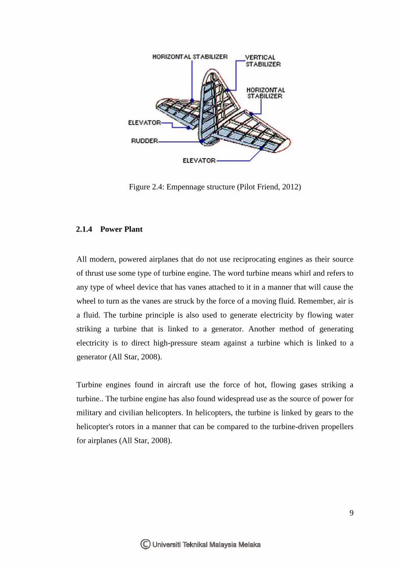
2.1.3 Empennage
The empennage consists of the stabilizing fins mounted on the tail section of the
fuselage. These include the vertical stabilizer on which is generally mounted the
rudder that is used to control yaw, or direction of the nose about the vertical axis; and
the horizontal stabilizer, on the trailing edge of which are the elevators that
determine the pitch (climb or dive).Some supersonic aircraft may have a full delta
wing. In that case, there is no horizontal stabilizer and the elevators and
ailerons are combined into control surfaces called elevons.
9
Figure 2.4: Empennage structure (Pilot Friend, 2012)
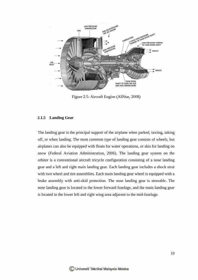
2.1.4 Power Plant
All modern, powered airplanes that do not use reciprocating engines as their source
of thrust use some type of turbine engine. The word turbine means whirl and refers to
any type of wheel device that has vanes attached to it in a manner that will cause the
wheel to turn as the vanes are struck by the force of a moving fluid. Remember, air is
a fluid. The turbine principle is also used to generate electricity by flowing water
striking a turbine that is linked to a generator. Another method of generating
electricity is to direct high-pressure steam against a turbine which is linked to a
generator (All Star, 2008).
Turbine engines found in aircraft use the force of hot, flowing gases striking a
turbine.. The turbine engine has also found widespread use as the source of power for
military and civilian helicopters. In helicopters, the turbine is linked by gears to the
helicopter's rotors in a manner that can be compared to the turbine-driven propellers
for airplanes (All Star, 2008).
10
Figure 2.5: Aircraft Engine (AllStar, 2008)
2.1.5 Landing Gear
The landing gear is the principal support of the airplane when parked, taxiing, taking
off, or when landing. The most common type of landing gear consists of wheels, but
airplanes can also be equipped with floats for water operations, or skis for landing on
snow (Federal Aviation Administration, 2006). The landing gear system on the
orbiter is a conventional aircraft tricycle configuration consisting of a nose landing
gear and a left and right main landing gear. Each landing gear includes a shock strut
with two wheel and tire assemblies. Each main landing gear wheel is equipped with a
brake assembly with anti-skid protection. The nose landing gear is steerable. The
nose landing gear is located in the lower forward fuselage, and the main landing gear
is located in the lower left and right wing area adjacent to the mid-fuselage.