Embed Size (px)
Citation preview
UNIVERSITI PUTRA MALAYSIA
DEVELOPMENT OF SCARA ROBOTIC ARM AND CONTROL SYSTEM FOR LABORATORY
AUTOMATION
JOHNNY KOH SIAW PAW
FK 2002 51
DEVELOPMENT OF SCARA ROBOTIC ARM AND CONTROL SYSTEM FOR LABORATORY AUTOMATION
By
JOHNNYKOBSIAWPAW
Thesis Submitted to the School of Graduate Studies, Universiti Putra Malaysia, in Fulfilment of the Requirement for the Degree of Master of Science
July 2002
Abstract of thesis presented to the Senate ofUniversiti Putra Malaysia in fulfilment of the requirements for the degree of Master of Science
DEVELOPMENT OF SCARA ROBOTIC ARM AND CONTROL SYSTEM FOR LABORATORY AUTOMATION
By
JOHNNYKOHSIAWPAW
July 2002
Chairman: Dr. Ishak Bin Aris
Faculty: Engineering
Recent developments in robotic system usage for material handlings, examine the
various benefits of its applications in the chemical industIy environment. In order
to avoid the risk factor in chemical handling, various steps can be taken. One of the
prominent methods is by substituting the human hands with the robotic ann in
handling dangerous and erosive chemicals. It is with these reasons that this study
was conducted with the primary objective to develop a system that would
contribute towards encouraging a safety way of chemical testing and processing.
This thesis provides an early analysis of robotic developments in the area
II

The objective of this project is to develop a SCARA robotic ann and the intelligent
control system. The design and development of this project involves three major
sections. First section concerns about software programming, while the second
section involves hardware construction and the final section deals with the graphic
user interfacing (GUI).
The hardware design can mainly be categorised into electrical design and
mechanical design. Electrical design involves proper electrical wiring of input and
output devices~ power distributions, safety devices, interfacing devices and control
components. The mechanical design is referred to the construction of the robot arm
structures. These comprise mechanical drawings, mechanical simulations,
mathematical calculations, as well as parts fabrication. On the other han~ the
design of software will consist of input and output assignments, program flow
charts, robot-learning method and MINT programming. Design of GUI will
involve Visual Basic (Professional Edition) programming.
Basically, this project comprises several subsystems, namely: a sensor system,
which is used to obtain data about the state of the mechanism and the environment,
a controller and drivers, to guide the mechanism and the sensors in a desired
manner, a planning and control system that decides on the actions and also consists
of a power distributions system. The specified function of the robotic system is
accomplished by intelligent interpretation of sensor infonnation and mechanical
actuations in tenn of plan, task and model.
111

The entire robotic system was carefully and meticulously designed, constructed
and tested. From the experimental results, it is proven that the proposed robotic
system was successfully developed. This robotic ann can handle hazardous tasks in
lab experiment specifically regarding chemical processing. Thus, reducing the risk
on human.
IV
Abstrak tesis yang dikemukakan kepada Senat Universiti Putra Malaysia sebagai memenuhi kepeduan untuk ijazah Master Sains
PEMBANGUNAN LENGAN ROBOT SCARA DAN SISTEM KA W ALAN UNTUKAUTOMAm~
Oleh
JOHNNY KOH SlAW PAW
Julai 2002
Pengerusi: Dr. Ishak Bin Aris
Falmlti: Kejuruteraan
Bam-bam ~ pembangunan dalam penggunaan sistem robotik untuk mengwuskan
bahan membuktikan pelbagai kebaikannya dalam industri bahan kimia. Demi
\Ultuk mengelak dari risiko pengendalian bahan kimia, pelbagai langkah boleh
diambil. Salah sam langkah penting ialah dengan menggantikan tangan manusia
dengan tangan robot untuk mengendalikan bahan-bahan kimia berbahaya dan
menghakis. Untuk tujuan inilah, kajian ini dijalankan dengan matlamat utama
untuk menghasilkan sebuah sistem yang dapat menyumbang kepada keselamatan
pemprosesan dan pengujian bahan kimia. Tesis ini menyediakan analisis awal
dalam pembangunan robot dalam bidang berkenaan.
v
Objektif projek adalah untuk menghasilkan sebuah robot jenis SCARA dengan
sistem kawalannya. Rekabentuk dan pembangunan projek akan melibatkan tiga
bahagian penting. Bahagian pertama menitikberatkan bidang perisian manakala
bahagian kedua meliputi pembinaan perkakasan, dan disusuIi dengan antaramuka
pengguna secara grafik.
Rekabentuk perkakasan bolehlah dikategorikan kepada rekabentuk elektrikal dan
rekabentuk mekanikal. Rekabentuk elektrikal merangkumi pendawaian alatan
masukan dan keluaran, pengagihan kuasa, peranti keselamatan dan komponen
kawalan. Rekabentuk mekanikal meliputi pembinaan struktur robot Ini termasuk
lukisan dan simulasi mekanikal, turut melibatkan pengiraan dan fabrikasi
bahagian-babagian robot Rekabentuk perisian pula akan meh1>atkan penugasan
masukan dan keluaran, carta-carta aliran program, teknik robot-bela jar dan
pengaturcaraan MINT. Semen tara, antaramuka grafik akan meliputi
pengaturcaraan Visual Basic.
Secara asasnya, projek ini membabitkan beberapa sub-sistem iaitu sistem penderia
yang digunakan untuk mendapatkan maklumat keadaan mekanisme dan
persekitaran, pengawal dan pemacu untuk mengawal mekanisme dan penderia,
sistem kawalan dan juga sistem pengagihan kuasa. Fungsi khas sistem robotik
dicapai dengan penterjemahan maklumat-maklumat penderia dan pemacuan
mekanikal.
VI

Keseluruhan sistem robotik ini telah direkabentuk, dibina dan diuji secara teliti.
Daripada keputusan ujikaji, temyata sistem robot yang dicadangkan telah berjaya
dihasilkan. Tangan robot ini berupaya untuk mengendalikan kerja-kerja berbahaya
dalam ujikaji makmal terutamanya pemprosesan bahan kimia. Pada masa yang
sarna, ini turut mengurangkan risiko kepada manusia.
vii
ACKNOWLEDGEMENTS
The success of this project involves many valued contributions from a
number of persons. I am grateful to my project supervisor, Dr. Ishak Aris for his
invaluable supervision, advice and guidance in the development of this project till
its completion. He has given me lot of encouragements, and supports that had
motivated me to successfully managed this project.
A word of thanks to the project co-supervisors, Dr. Sinan Mahmod and
Prof. Madya Jr. Dr. Norman Mariun, who gave us the opportunity and support to
handle this project. I would also like to thank the staffs of Faculty of Engineering,
especially to En. Tajul Ariffin and En. Muzamir for their contribution in providing
the related supporting materials.
I am deeply indebted to Mr. S. Y. Koh and Mr. S.K. Koh, the managers of
Autocomsign Enterprise, who have shared their expertise and comments. Mr. Y.S.
Chee, Mr. J.H. Ong and Mr. Y.K. Tai, whose professional careers have always
revolved around motion control, reviewed the motion systems chapter for me, and
participated in many more technical discussions. Finally, thanks to my colleague
Jenny Teh, who has given me great support on this project.
It is my hope that this report will contribute to the organisations in
furthering their research.
viii
I certify that an Examination Committee met on 11th July 2002 to conduct the final examination of Johnny Koh Siaw Paw on his Master of Science thesis entitled "Development of Scara Robotic Ann and Control System for Laboratory Automation" in accordance with Universiti Pertanian Malaysia (Higher Degree) Act 1980 and Universiti Pertanian Malaysia (Higher Degree) Regulations 1981. The Committee recommends that the candidate be awarded the relevant degree. Members of the Examination Committee are as follows:
NASRULLAH KHAN, Ph.D. Faculty of Engineering, Universiti Putra Malaysia (Chairman)
ISHAK BIN ARIS, Ph.D. Faculty of Engineering, Universiti Putra Malaysia (Member)
SINAN MAHMOD, Ph.D. Facuhy of Engineering, Universiti Putra Malaysia (Member)
NORMAN MARIUN, Ph.D. Associate Professor Faculty of Engineering, Universiti Putra Malaysia (Member)
~ -:J SHAMSHER MOHAMAD RAMADILI, Ph.D. ProfessorlDeputy Dean School of Graduate Studies Universiti Putra Malaysia
Date: 1 j SEP 2002
IX
This thesis submitted to the Senate of Universiti Putra Malaysia has been accepted as fulfillment of the requirement for the degree of Master of Science. The members of the Supervisory Committee are as follows:
ISHAK BIN ARIS, Ph.D. Faculty of Engineering, Universiti Putra Malaysia (Member)
SINAN MAHMOD, Ph.D. Faculty of Engineering, Universiti Putra Malaysia (Member)
NORMAN MARIUN, Ph.D. Associate Professor Faculty of Engineering, Universiti Putra Malaysia (Member)
AINI IDERIS, Ph.D. Professor/ Dean, School of Graduate Studies, Universiti Putra Malaysia
Date:
x
I hereby declare that the thesis is based on my original work except for quotations and citations, which have been duly acknowledged. I also declare that it has not been previously or concurrently submitted for any other degree at UPM or other institutions.
JOHNNYKOHSIAWPAW
Xl
TABLE OF CONTENTS
Page
ABSTRACT 11
ABSTRAK ACKNOWLEDGEMENTS APPROVAL SHEETS DECLARATION FORM LIST OF TABLES
v viii IX
Xl
xv XVI
XXI
XXll
LIST OF FIGURES LIST OF ABBREVIATIONS LIST OF SYMBOLS
CHAPTER
1 INTRODUCTION 1.1 Introduction 1.2 Objectives of the Project 1.3 Overview of the Project 1.4 Layout of the Thesis
l.1 l.4 l.5 l.9
2 LITERATURE REVIEW 2.1 Modem Technology of Robots 2.1 2.2 Applications of Robot 2.3 2.3 Laws of Robots 2.5 2.4 Classification of Robots 2.6 2.5 Robot Configurations 2.7 2.6 Drive Technology 2.9 2.7 Types of Robotic Controller and Programming Software 2.10
2.7.1 Smart Step Controller 2.11 2.7.2 Motion Interpreter (MINT) Language 2.13 2.7.3 Terminal Emulator (cTERM) 2.14 2.7.4 Programming Technique Using MINT and
Terminal Emulator for Developing the Control Software 2.14
2.7.5 Graphic User Interfacing (GUI) 2.16 2.7.6 Technique of Using Visual Basic for Development
ofGUI 2.17 2.8 Intelligent Robotic Systems 2.] 8 2.9 The Main Types of Robot-Learning 2.20
2.9.1 Learning Functions 2.21 2.9.2 Learning About the World 2.22 2.9.3 Learning to Coordinate Behaviours 2.22
XlI
2.9.4 Learning New Behaviours 2.10 Summary of Literature Review
3 METHODOLOGY
2.23 2.24
3.1 Overview 3.1 3.2 Software Design and Development 3.3
3.2.1 System Control Software 3.3 3.2.1.1 MainProgram 3.4 3.2.1.2 Process Routine 3.6 3.2.1.3 Learning Routine 3.8 3.2.1.4 Inputs and Outputs Assignment 3.13
3.2.2 Development of the GUI for the Proposed Robot 3.15 3.2.2.1 Graphical Design 3.16 3.2.2.2 Parallel Port Control 3.18
3.3 Hardware Development 3.20 3.3.1 Electrical Design 3.21
3.3.1.1 Electrical Protection System 3.21 3.3.1.2 Power Distribution System 3.23 3.3.1.3 Input and Output Module 3.25 3.3.1.4 Electro-Pneumatic Based Gripper System 3.32 3.3.1.5 Stepper Motor Control 3.35 3.3.1.6 110 Isolation Card for GUI 3.39 3.3.1.7 Controller Wiring 3.40
3.3.2 Mechanical Design 3.42 3.3.2.1 Elevation Module 3.43 3.3.2.2 Upper Arm and Fore Arm Modules 3.47 3.3.2.3 Gripper Module 3.52 3.3.2.4 Leadscrew, Belt and Bearing Systems 3.53 3.3.2.5 Jigs, Fixtures and Mechanical Base 3.54
3.4 System Integration 3.55
4 RESULTS AND DISCUSSION 4.1 Overview 4.1 4.2 Hardware Testing 4.1
4.2.1 Electrical Module 4.2 4.2.1.1 Electrical Protection System 4.2 4.2.1.2 Power Distribution System 4.3 4.2.1.3 Input and Output Module 4.4 4.2.1.4 Electro-Pneumatic Based Gripper System 4.7 4.2.1.5 Stepper Motor Control 4.8 4.2.1.6 GUl 110 Isolation Card 4.12
4.2.2 Mechanical Modules 4.14 4.2.2.1 Elevation Module 4.14 4.2.2.2 Upper Arm and Fore Arm Modules 4.17 4.2.2.3 Gripper System 4.30 4.2.2.4 Kinematics Analysis 4.31
XlII
5
4.3 Software Testing 4.3.1 Process Routine 4.3.2 Learning Routine 4.3.3 Graphical User Interfacing
4.4 System Integration
CONCLUSION 5.1 Conclusion 5.2 Recommendations
REFERENCES
APPENDICES
VITA
Appendix A: Mechanical Drawings Appendix B: Program Appendix C: Electrical Design Appendix D: Mechanical Components Appendix E: Electrical Components Appendix F: Pneumatic System
4.39 4.39 4.40 4.42 4.43
5.1 5.3
R.I
A.I B.1 C.1 D.1 E.1 F.l
V.I
XIV
Table
3.1
3.2
3.3
3.4
3.5
3.6
4.1
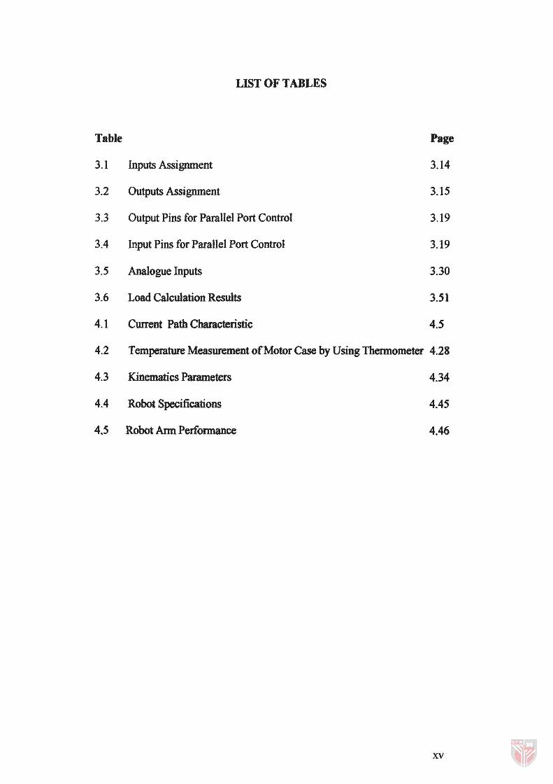
LIST OF TABLES
Inputs Assignment
Outputs Assignment
Output Pins for Parallel Port Control
Input Pins for Parallel Port Control
Analogue Inputs
Load Calculation Results
Current Path Characteristic
Page
3.14
3.15
3.l9
3.19
3.30
3.51
4.5
4.2 Temperature Measurement of Motor Case by Using Thermometer 4.28
4.3 Kinematics Parameters
4.4 Robot Specifications
4.5 Robot Arm Performance
4.34
4.45
4.46
xv
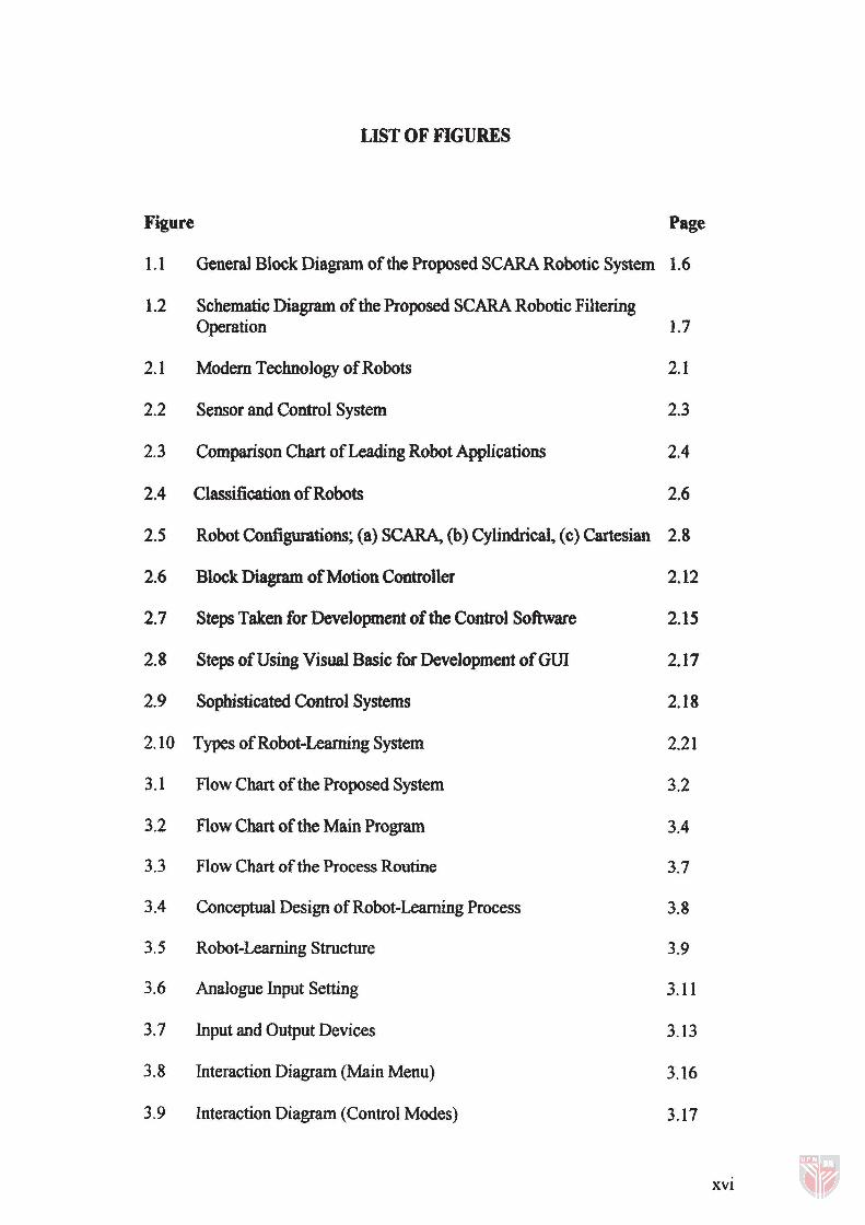
LIST OF FIGURES
Figure Page
1.1 General Block Diagram of the Proposed SCARA Robotic System 1.6
1.2 Schematic Diagram of the Proposed SCARA Robotic Filtering Operation 1.7
2.1 Modern Technology of Robots 2.1
2.2 Sensor and Control System 2.3
2.3 Comparison Chart of Leading Robot Applications 2.4
2.4 Classification of Robots 2.6
2.5 Robot Configurations; (a) SCARA, (b) Cylindrical, (c) Cartesian 2.8
2.6 Block Diagram of Motion Controller 2.12
2.7 Steps Taken for Development of the Control Software 2.15
2.8 Steps of Using Visual Basic for Development ofGUI 2.17
2.9 Sophisticated Control Systems 2.18
2.10 Types of Robot-Learning System 2.21
3.1 Flow Chart of the Proposed System 3.2
3.2 Flow Chart of the Main Program 3.4
3.3 Flow Chart of the Process Routine 3.7
3.4 Conceptual Design of Robot-Leaming Process 3.8
3.5 Robot-Learning Structure 3.9
3.6 Analogue Input Setting 3.11
3.7 Input and Output Devices 3.13
3.8 Interaction Diagram (Main Menu) 3.16
3.9 Interaction Diagram (Control Modes) 3.17
XVI
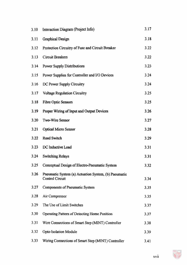
3.10 Interaction Diagram (Project Info) 3.17
3.11 Graphical Design 3.18
3.12 Protection Circuitry of Fuse and Circuit Breaker 3.22
3.13 Circuit Breakers 3.22
3.14 Power Supply Distributions 3.23
3.15 Power Supplies for Controller and I/O Devices 3.24
3.16 DC Power Supply Circuitry 3.24
3.17 Voltage Regulation Circuitry 3.25
3.18 Fibre Optic Sensors 3.25
3.19 Proper Wiring of Input and Output Devices 3.26
3.20 Two-Wire Sensor 3.27
3.21 Optical Micro Sensor 3.28
3.22 Reed Switch 3.29
3.23 DC Inductive Load 3.31
3.24 Switching Relays 3.31
3.25 Conceptual Design of Electro-Pneumatic System 3.32
3.26 Pneumatic System (a) Actuation System, (b) Pneumatic Control Circuit 3.34
3.27 Components of Pneumatic System 3.35
3.28 Air Compressor 3.35
3.29 The Use of Limit Switches 3.37
3.30 Operating Pattern of Detecting Home Position 3.37
3.31 Wire Connections of Smart Step (MINT) Controller 3.38
3.32 Opto-Isolation Module 3.39
3.33 Wiring Connections of Smart Step (MINT) Controller 3.41
XVlI
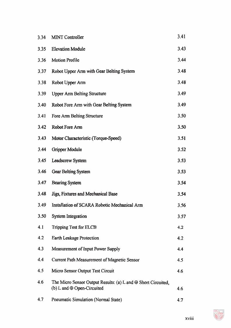
3.34 MINT Controller 3.41
3.35 Elevation Module 3.43
3.36 Motion Profile 3.44
3.37 Robot Upper Ann with Gear Belting System 3.48
3.38 Robot Upper Ann 3.48
3.39 Upper Ann Belting Structure 3.49
3.40 Robot Fore Ann with Gear Belting System 3.49
3.41 Fore Ann Belting Structure 3.50
3.42 Robot Fore Ann 3.50
3.43 Motor Characteristic (Torque-Speed) 3.51
3.44 Gripper Module 3.52
3.45 Leadscrew System 3.53
3.46 Gear Belting System 3.53
3.47 Bearing System 3.54
3.48 Ji~ Fixtures and Mechanical Base 3.54
3.49 Installation of SCARA Robotic Mechanical Arm 3.56
3.50 System Integration 3.57
4.1 Tripping Test for BLCB 4.2
4.2 Earth Leakage Protection 4.2
4.3 Measurement of Input Power Supply 4.4
4.4 Current Path Measurement of Magnetic Sensor 4.5
4.5 Micro Sensor Output Test Circuit 4.6
4.6 The Micro Sensor Output Results: (a) Land e Short Circuited, (b) L and e Open-Circuited 4.6
4.7 Pneumatic Simulation (Nonnal State) 4.7
xviii
4.8 Pneumatic Simulation (Active State) 4.8
4.9 MINT Controller Testing Circuit 4.9
4.10 Increment of Phase Current Effect on Torque 4.10
4.11 Pulse Train for Stepper Motor Driver 4.12
4.12 Opto-Isolation 4.13
4.13 Switching Circuit 4.14
4.14 Specification of Leadscrew for the Elevation Module 4.15
4.15 Motion Profile of Elevation Module 4.15
4.16 Torque-Speed Characteristic of Elevation Module 4.16
4.17 Positioning Accuracy 4.16
4.18 Specification of Gear Belting System for the Arm Modules 4.18
4.19 Motion Profile of Upper Arm and Fore Arm 4.19
4.20 Torque-Speed Characteristic of Upper Arm and Fore Arm 4.20
4.21 Stop Angle Accuracy 4.22
4.22 Step Angle Accuracy 4.22
4.23 Torque-Speed Characteristic 4.23
4.24 Measuring the Temperature of Motor Case Using Thermometer 4.26
4.25 Graph of Temperature Rise in Motor Case 4.28
4.26 Linkage Coordinates of a 3-Axis SCARA Robot 4.32
4.27 Elevation Module Linkage Mechanism 4.34
4.28 Upper Arm and Fore Arm Linkage Mechanism 4.35
4.29 Working Envelope of the SCARA Robotic System 4.38
4.30 Array Data File 4.41
4.31 GUlI/O Isolation Test Circuit 4.42
4.32 Graphical Control Testing 4.42
XIX
4.33 Mechanical Structure
4.34 Electrical Wiring
4.35 Teaching Unit and Control Pendant
4.36 Process of the Proposed Project
4.43
4.43
4.44
4.47
xx
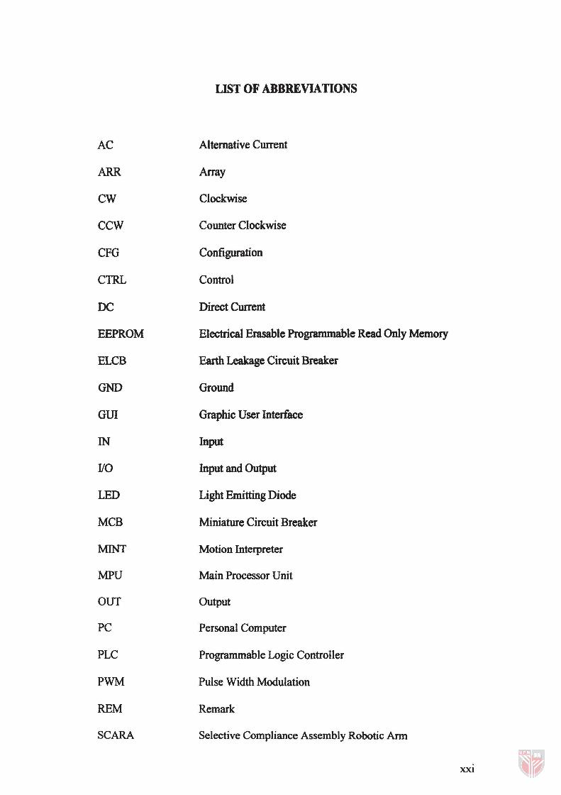
LIST OF ABBREVIATIONS
AC Alternative Current
ARR Array
CW Clockwise
CCW Counter Clockwise
CFG Configuration
CTRL Control
DC Direct Current
EEPROM Electrical Erasable Programmable Read Only Memory
ELCB Earth Leakage Circuit Breaker
GND Ground
GUI Graphic User Interface
IN Input
110 Input and Output
LED Light Emitting Diode
MCB Miniature Circuit Breaker
MINT Motion Interpreter
MPU Main Processor Unit
OUT Output
PC Personal Computer
PLC Programmable Logic Controller
PWM Pulse Width Modulation
REM Remark
SCARA Selective Compliance Assembly Robotic Arm
XXI
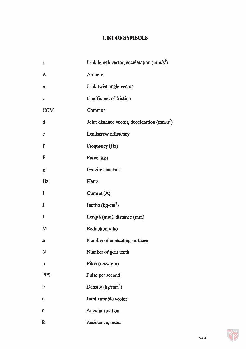
LIST OF SYMBOLS
a Link length vector, acceleration (mm/s2)
A Ampere
a Link twist angle vector
c Coefficient of friction
COM Common
d Joint distance vector, deceleration (mm/s2)
e Leadscrewefficiency
f Frequency (Hz)
F Force (kg)
g Gravity constant
Hz Hertz
I Current (A)
J Inertia (kg-cm2)
L Length (mm), distance (mm)
M Reduction ratio
n Number of contacting surfaces
N Number of gear teeth
p Pitch (revs/mm)
PPS Pulse per second
p Density (kglmm3)
q Joint variable vector
r Angular rotation
R Resistance, radius
XXIl
rpm Revolution per minute
s Second, safety factor
S Step angle C), sensing distance (mm)
T Torque (Nm), transfonnation
t Time (sec), temperature CC)
Ils Coefficient of static friction
V Voltage (volt)
v Velocity (mm1sec)
W Weight (kg)
Ol Angular velocity (rad/sec)
X Linear translation
n Ohm
xxiii
CHAPTER!
INTRODUCTION
1.1 Introduction
Science and technology pJay a major role in Malaysia's dynamic
industrialisation. In the spirit of~Malaysia incorporated' promulgated by the Prime
Minister Dr. Mahathir Mohammad since 1983, the public and private sectors have
been very supportive of science and technology developments in Malaysia.
National awareness and interest in science and techne>le>gy must be enhanced, as
this constitutes a prerequisite for an inventive society. Inventing is a suitable
approach to help make science and technology more interesting and relevant to the
industries and economy. The spirit of inventiveness should be inculcated among
Malaysians.
There are various types of inventions ranging from simple to complex base
on its functionality and needs by the various industries. One of the quite prominent
types is robotic invention. In an industrialisation era, robotics have certainly played
a very important role not only in minimising and easing work burden but also to
the extend of increasing productivity and not compromising on products quality.
This has certainly brought prosperity to many countries such as Japan and Korea.
In order to "mimic" this significant achievement, our Prime Minister had launched
1.1