Embed Size (px)
Citation preview
UNIVERSAL HYDRAULIC STEERING KITINSTALLATION GUIDE FOR CLOSEDCENTER, LOAD-SENSE W/SHUTTLE
CHECK, HYDRAULIC SYSTEMS117-9001-021
DISCLAIMERWhile every effort has been made to ensure the accuracy of this document, RavenIndustries assumes no responsibility for omissions and errors. Neither is any liabilityassumed for damages resulting from the use of information contained herein.
Raven Industries shall not be held responsible or liable for the effects of atmosphericconditions and sunspot activity on the performance of our products.
Raven Industries cannot guarantee the accuracy, integrity, continuity, or availability ofthe GPS signal from the US Department of Defense/NAVSTAR GPS satellites, theOmniSTAR correction service or the WAAS correction service.
Raven Industries accepts no responsibility for the use of the signal for other than thestated purpose. Raven Industries shall not be responsible or liable for incidental orconsequential damages or a loss of anticipated benefits or profits, work stoppage orloss or impairment of data arising out of the use or inability to use the Smartrax or anyof its components.
1
TABLE OF CONTENTS016-9001-019 04/05
INTRODUCTION .................................................................................................................................. 3ABOUT THIS GUIDE ........................................................................................................................... 4
WHO IT IS FOR ....................................................................................................................... 4WHAT IT COVERS .................................................................................................................. 4UPDATES................................................................................................................................. 4
INSTALLATION SAFETY REQUIREMENTS ...................................................................................... 5SAFETY PRECAUTIONS ........................................................................................................ 5HYDRAULIC SAFETY PRECAUTIONS .................................................................................. 6ELECTRICAL SAFETY PRECAUTIONS................................................................................. 6SAFETY SYMBOLS ................................................................................................................. 6
SAFETY WARNING LABELS .............................................................................................................. 7STEERING POSITION SENSOR WARNING LABEL ............................................................. 7HYDRAULIC WARNING LABEL.............................................................................................. 7
DRIVING SAFETY REQUIREMENTS ................................................................................................. 8AREAS OF OPERATION......................................................................................................... 8AVOIDANCE OF PEOPLE....................................................................................................... 8AVOIDANCE OF MACHINERY AND EQUIPMENT ................................................................ 8AVOIDANCE OF OBSTACLES ............................................................................................... 8RESPONSIBILITIES OF OPERATOR..................................................................................... 8DISENGAGING STEERING ASSIST ...................................................................................... 9OPERATIONAL EMERGENCY SAFETY STEPS ................................................................... 9
OTHER REFERENCES ....................................................................................................................... 9CONTACTING RAVEN INDUSTRIES ................................................................................................. 9INSTALLING HYDRAULIC COMPONENTS .................................................................................... 10INSTALLING THE HYDRAULIC BRACKET ...................................................................................... 11MOUNTING THE VALVE TO THE BRACKET .................................................................................. 12HYDRAULIC SYSTEM INSTALLATION............................................................................................ 16SAFETY PRECAUTIONS FOR CONNECTING HYDRAULIC HOSES ............................................ 16HYDRAULIC STEERING SETUP BEFORE AND AFTER INSTALLATION..................................... 17INSTALLING HYDRAULIC COMPONENTS ..................................................................................... 18INSTALLING THE SHUTTLE VALVE AND PRESSURE SWITCH .................................................. 22INSTALLING THE STEERING CONTROL VALVE HOSES ............................................................. 22HYDRAULIC SYSTEM CHECKS AND SETUP ................................................................................. 24SETTING THE VALVE SPOOL STOPS ............................................................................................ 24SETTING THE OVERRIDE PRESSURE SWITCH ........................................................................... 26CABLE CONNECTION AND ROUTING ........................................................................................... 27OVERVIEW OF CABLE CONNECTION AND ROUTING ................................................................. 28SMARTRAX LOOM ROUTING .......................................................................................................... 29SOLENOID CABLE CONNECTION & ROUTING ............................................................................. 30
SOLENOID CABLE CONNECTION - TYPE 1 ...................................................................... 30STEERING POSITION SENSOR (S.P.S.) CABLE CONNECTION AND ROUTING ....................... 32
2
Diagrams and Figures
Steering Position Sensor Warning label .....................................................................................................7Hydraulic Warning label ............................................................................................................................7Valve Mounting Bracket .......................................................................................................................... 11Bracket Mounting Plate .......................................................................................................................... 11Hydraulic Valve Mounting Holes ....................................................................................................... 12 - 15Steering Block Diagram before installation ..............................................................................................17Steering Block Diagram after installation .................................................................................................17Steering Control Valve Labelled ..............................................................................................................18Hydraulic System Layout ................................................................................................................. 20 - 21Steering Control Valve Spool Stop Screws Labelled .................................................................................24Pressure Switch.....................................................................................................................................26Solenoid cable connection type 1 to Smartrax Loom ................................................................................31
3
Introduction
About This GuideInstallation Safety Requirements
Safety Warning LabelsDriving Safety Requirements
Other ReferencesContacting RAVEN INDUSTRIES
4
About This Guide
The aim of this guide is to provide up to date reference information about installation of the SmarTraxproduct.
Who it is for
This guide is intended for use by distributors who install new SmarTrax systems for Raven Industries.
What it covers
This guide presents:
• a parts checklist for the steering installation;• installation procedures for the SMARTRAX hydraulic kit and cable routing
Updates
This guide will be updated periodically to reflect changes and additions to the range of SmarTraxproducts and to ensure that this guide fulfills users’ needs for reference information. Updates will besupplied as soon as they are available.
5
Installation Safety Requirements
This section is divided between general safety precautions, specific safety measures in respect of thehydraulic and electrical system, and safety symbols used in this document.
Safety Precautions
When working with or near a machine with SmarTrax installed, the following safety measures must beobserved. The operator must:
• Be alert and aware of surroundings.
• Not operate the SmarTrax while under the influence of alcohol or an illegal substance.
• Remain in the operator’s position in the machine at all times when the SmarTrax is engaged.
• Be in complete control of the machine at all times when the SmarTrax is engaged.
• Disengage the SmarTrax when exiting from the operator’s position and machine.
• Remain within the boundaries of a defined field when the SmarTrax is engaged.
• Not drive the machine with the SmarTrax engaged on any public thoroughfare or main road.
• Determine and remain a safe working distance from other machinery, equipment, and obstacles.The operator is responsible for disengaging the SmarTrax when the safe working distance hasdiminished.
• Determine and remain a safe working distance from other farm personnel or people. Theoperator is responsible for disengaging the SmarTrax when the safe working distance hasdiminished.
• Ensure the SmarTrax is disengaged prior to starting any maintenance work on the SmarTrax ormachine.
The machine must remain stationary and switched off, and Steering AssistTM disengagedwhile installation or maintenance is being carried out.
6
Hydraulic Safety Precautions
When disconnecting hydraulic hoses or when purging is required, be aware that the hydraulic oilwithin the machine system may be hot and under high pressure. Caution must be exercised.Any work carried out on the hydraulics system must be performed in accordance with the machinemanufacturer’s approved maintenance instructions.
Raven Industries recommend that appropriate protective equipment be worn when working on thehydraulics system.
It is imperative that, when installing the SmarTrax hydraulics, performing diagnostics, maintenance,or routine machine servicing, that installers and customers ensure all precautions are taken toprevent any foreign material or contaminants from being introduced into the machine’s hydraulicsystem.
Objects or materials that are able to bypass the machine’s hydraulic filtration system will adverselyreduce performance, and possibly damage the SmarTrax hydraulic valves.
Electrical Safety Precautions
Do not reverse the power leads. Doing so will cause severe damage to the equipment. Always checkto make sure that the power leads are connected to the right polarity as marked.Ensure that the power cable is the last cable to be connected.
Safety Symbols
WARNING: Identifies information about practices or circumstances that can lead topersonal injury or death, property damage or economic loss.
Warning statements help you to:
• Identify a hazard.• Avoid a hazard.• Recognize consequences.
NOTE: Identifies information that is critical for successful application and understandingof the product.
WARNING
7
Safety Warning Labels
Safety Warning Labels have been provided to highlight to users the importance of:
• Being aware not to damage the wheel angle sensor.• Not tampering with the SmarTrax hydraulics valves.
These warning labels are to be placed in the specified locations as indicated below.
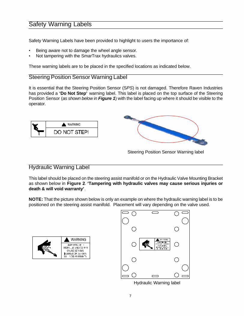
Steering Position Sensor Warning Label
It is essential that the Steering Position Sensor (SPS) is not damaged. Therefore Raven Industrieshas provided a ‘Do Not Step’ warning label. This label is placed on the top surface of the SteeringPosition Sensor (as shown below in Figure 1) with the label facing up where it should be visible to theoperator.
Steering Position Sensor Warning label
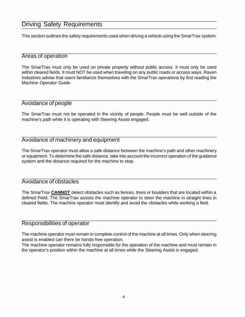
Hydraulic Warning Label
This label should be placed on the steering assist manifold or on the Hydraulic Valve Mounting Bracketas shown below in Figure 2. ‘Tampering with hydraulic valves may cause serious injuries ordeath & will void warranty’.
NOTE: That the picture shown below is only an example on where the hydraulic warning label is to bepositioned on the steering assist manifold. Placement will vary depending on the valve used.
Hydraulic Warning label
8
Driving Safety Requirements
This section outlines the safety requirements used when driving a vehicle using the SmarTrax system.
Areas of operation
The SmarTrax must only be used on private property without public access. It must only be usedwithin cleared fields. It must NOT be used when traveling on any public roads or access ways. RavenIndustries advise that users familiarize themselves with the SmarTrax operations by first reading theMachine Operator Guide.
Avoidance of people
The SmarTrax must not be operated in the vicinity of people. People must be well outside of themachine’s path while it is operating with Steering Assist engaged.
Avoidance of machinery and equipment
The SmarTrax operator must allow a safe distance between the machine’s path and other machineryor equipment. To determine the safe distance, take into account the incorrect operation of the guidancesystem and the distance required for the machine to stop.
Avoidance of obstacles
The SmarTrax CANNOT detect obstacles such as fences, trees or boulders that are located within adefined Field. The SmarTrax assists the machine operator to steer the machine in straight lines incleared fields. The machine operator must identify and avoid the obstacles while working a field.
Responsibilities of operator
The machine operator must remain in complete control of the machine at all times. Only when steeringassist is enabled can there be hands-free operation.The machine operator remains fully responsible for the operation of the machine and must remain inthe operator’s position within the machine at all times while the Steering Assist is engaged.
9
Disengaging steering assist
The operator must disengage the Steering Assist if an obstacle is in the line of travel. The operatormust disengage Steering Assist by using one of the following methods listed below.
Turning the steering wheel in the normal manner, stopping the machine, or pressing the remoteactivation switch can disengage steering Assist.
Operational emergency safety steps
In case of an emergency, take one of the following steps to disengage Steering Assist:
• Press the brake and decelerate to under 0.6 mph / 1 kph;• Turn the steering wheel in the normal manner; or• Pressing the remote activation switch.
Other References
Contacting RAVEN INDUSTRIES
We welcome your feedback about this guide.If you have any comments or suggestions for improvements, please let us know by contacting ourCustomer Support Center by any of the methods below:
By phone1-800-243-5435
By mail
Raven IndustriesFlow Controls Division205 E. 6th St.Sioux Falls, SD 57104
10
Installing Hydraulic Components
Installing the Hydraulic BracketMounting the Valve to the Bracket
Hydraulic System InstallationSafety Precautions for Connecting Hydraulic HosesHydraulic Steering Setup Before & After Installation
Installing Hydraulic ComponentsInstalling the Steering Control Valve Hoses
Hydraulic System Checks and SetupSetting the Valve Spool StopsAdjusting the Sequence Valve
Setting the Override Pressure SwitchInstalling the Rotary Steering Position Sensor (SPS)
11
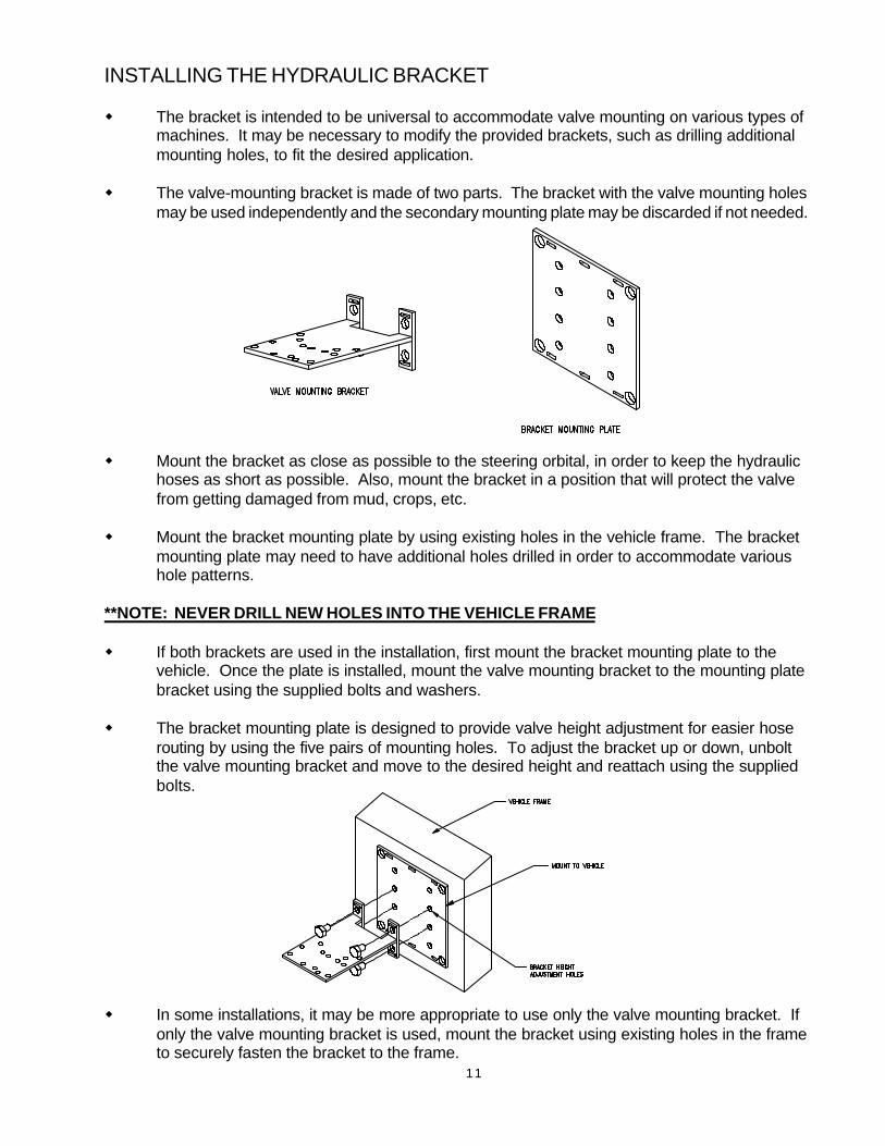
INSTALLING THE HYDRAULIC BRACKET
w The bracket is intended to be universal to accommodate valve mounting on various types ofmachines. It may be necessary to modify the provided brackets, such as drilling additionalmounting holes, to fit the desired application.
w The valve-mounting bracket is made of two parts. The bracket with the valve mounting holesmay be used independently and the secondary mounting plate may be discarded if not needed.
w Mount the bracket as close as possible to the steering orbital, in order to keep the hydraulichoses as short as possible. Also, mount the bracket in a position that will protect the valvefrom getting damaged from mud, crops, etc.
w Mount the bracket mounting plate by using existing holes in the vehicle frame. The bracketmounting plate may need to have additional holes drilled in order to accommodate varioushole patterns.
**NOTE: NEVER DRILL NEW HOLES INTO THE VEHICLE FRAME
w If both brackets are used in the installation, first mount the bracket mounting plate to thevehicle. Once the plate is installed, mount the valve mounting bracket to the mounting platebracket using the supplied bolts and washers.
w The bracket mounting plate is designed to provide valve height adjustment for easier hoserouting by using the five pairs of mounting holes. To adjust the bracket up or down, unboltthe valve mounting bracket and move to the desired height and reattach using the suppliedbolts.
w In some installations, it may be more appropriate to use only the valve mounting bracket. Ifonly the valve mounting bracket is used, mount the bracket using existing holes in the frameto securely fasten the bracket to the frame.
12
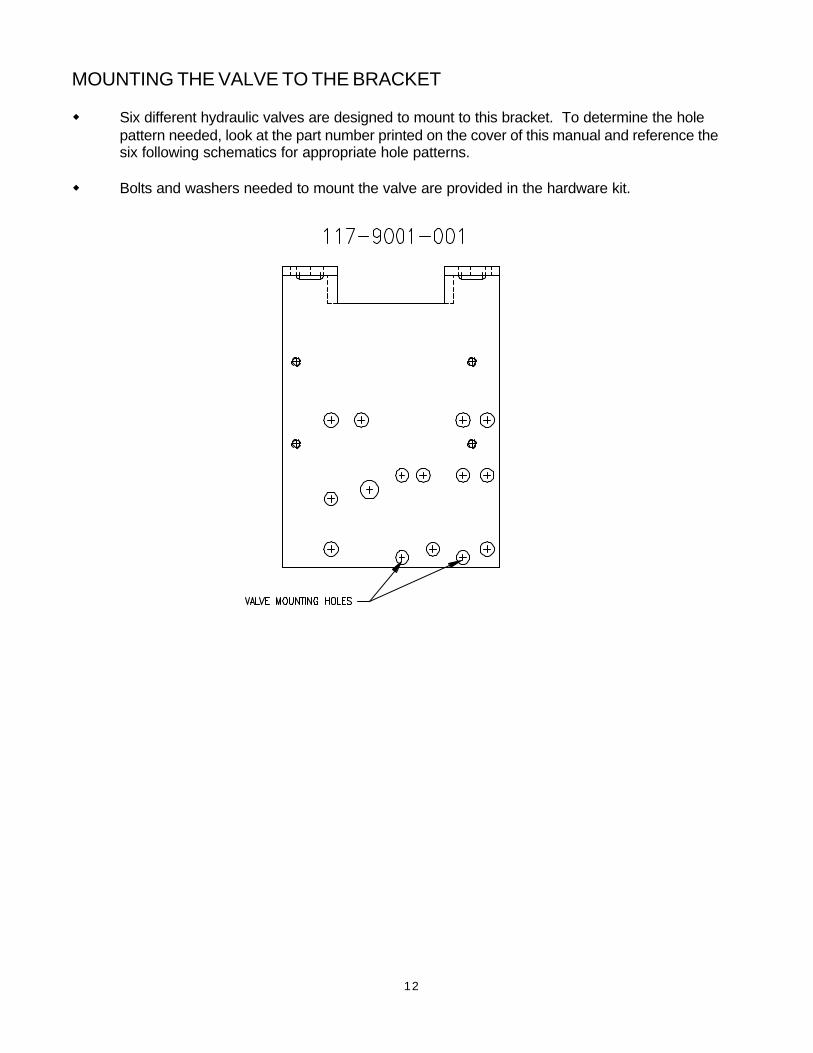
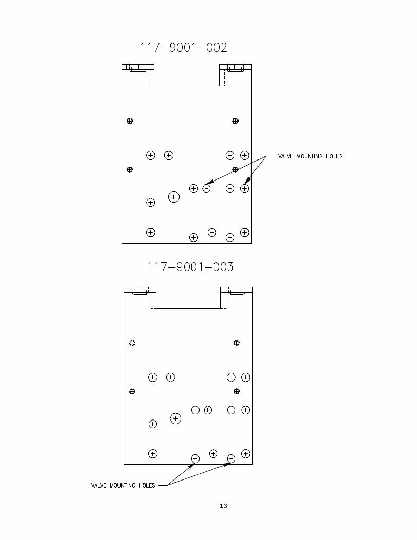
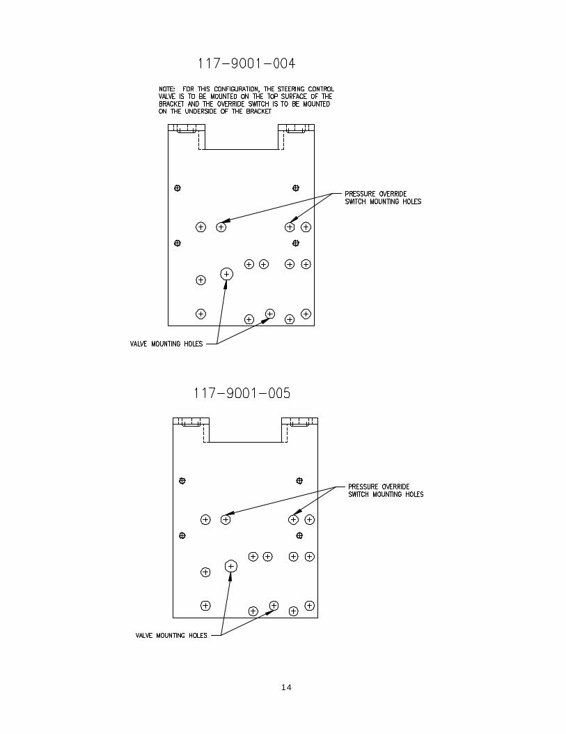
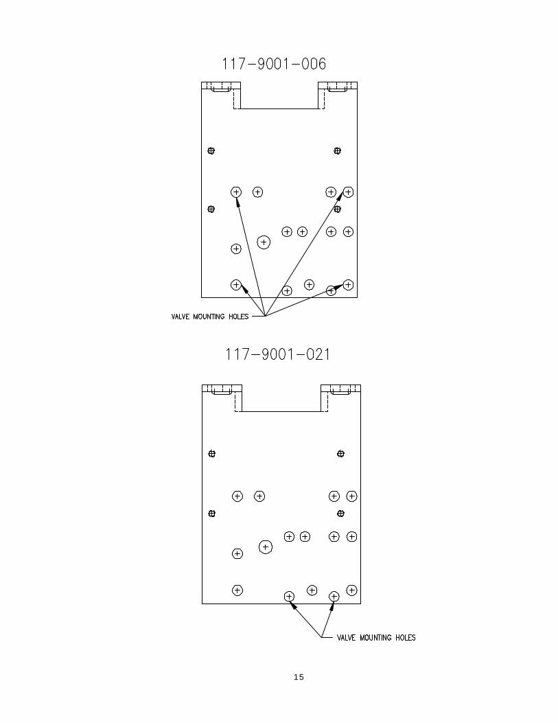
MOUNTING THE VALVE TO THE BRACKET
w Six different hydraulic valves are designed to mount to this bracket. To determine the holepattern needed, look at the part number printed on the cover of this manual and reference thesix following schematics for appropriate hole patterns.
w Bolts and washers needed to mount the valve are provided in the hardware kit.
13
14
15
16
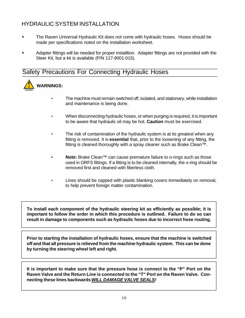
Safety Precautions For Connecting Hydraulic Hoses
WARNINGS:
• The machine must remain switched off, isolated, and stationary, while installationand maintenance is being done.
• When disconnecting hydraulic hoses, or when purging is required, it is importantto be aware that hydraulic oil may be hot. Caution must be exercised.
• The risk of contamination of the hydraulic system is at its greatest when anyfitting is removed. It is essential that, prior to the loosening of any fitting, thefitting is cleaned thoroughly with a spray cleaner such as Brake Clean™.
• Note: Brake Clean™ can cause premature failure to o-rings such as thoseused in ORFS fittings. If a fitting is to be cleaned internally, the o-ring should beremoved first and cleaned with fiberless cloth.
• Lines should be capped with plastic blanking covers immediately on removal,to help prevent foreign matter contamination.
WARNING
To install each component of the hydraulic steering kit as efficiently as possible; it isimportant to follow the order in which this procedure is outlined. Failure to do so canresult in damage to components such as hydraulic hoses due to incorrect hose routing.
Prior to starting the installation of hydraulic hoses, ensure that the machine is switchedoff and that all pressure is relieved from the machine hydraulic system. This can be doneby turning the steering wheel left and right.
It is important to make sure that the pressure hose is connect to the “P” Port on theRaven Valve and the Return Line is connected to the “T” Port on the Raven Valve. Con-necting these lines backwards WILL DAMAGE VALVE SEALS!
HYDRAULIC SYSTEM INSTALLATION
w The Raven Universal Hydraulic Kit does not come with hydraulic hoses. Hoses should bemade per specifications noted on the installation worksheet.
w Adapter fittings will be needed for proper installtion. Adapter fittings are not provided with theSteer Kit, but a kit is available (P/N 117-9001-015).
17
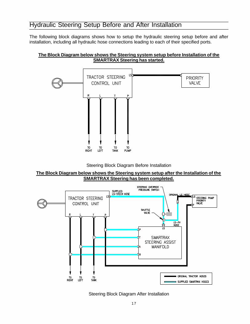
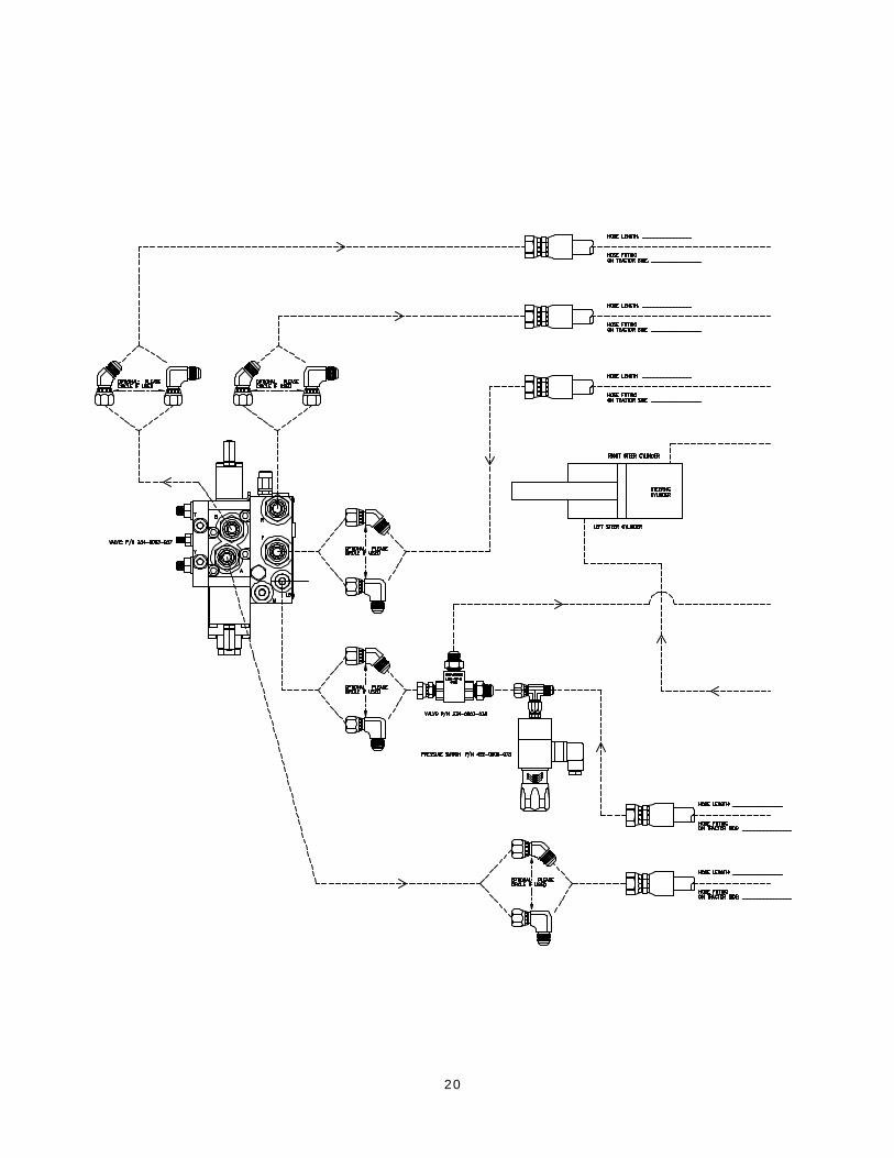
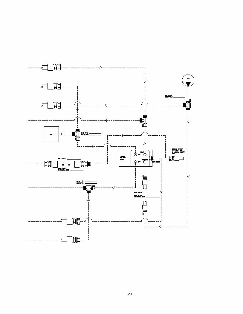
Hydraulic Steering Setup Before and After Installation
The following block diagrams shows how to setup the hydraulic steering setup before and afterinstallation, including all hydraulic hose connections leading to each of their specified ports.
The Block Diagram below shows the Steering system setup before Installation of theSMARTRAX Steering has started.
Steering Block Diagram Before Installation
The Block Diagram below shows the Steering system setup after the Installation of theSMARTRAX Steering has been completed.
Steering Block Diagram After Installation
18
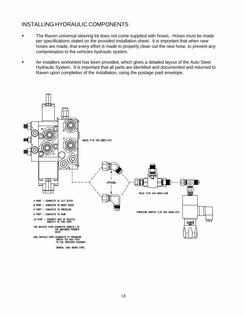
INSTALLING HYDRAULIC COMPONENTS
w The Raven universal steering kit does not come supplied with hoses. Hoses must be madeper specifications stated on the provided installation sheet. It is important that when newhoses are made, that every effort is made to properly clean out the new hose, to prevent anycontamination to the vehicles hydraulic system.
w An installers worksheet has been provided, which gives a detailed layout of the Auto SteerHydraulic System. It is important that all parts are identified and documented and returned toRaven upon completion of the installation, using the postage paid envelope.

19
THIS PAGE INTENTIONALLY LEFT BLANK
20
21
22
INSTALLING THE SHUTTLE VALVE AND PRESSURE SWITCHSEE HYDRAULIC DIAGRAM FOR SYSTEM LAYOUT
1. Connect 9/16” (F) JIC fitting coming out of the side of the check valve directly to the LS portof Smartrax Steering valve. NOTE: A 90o fitting may be used if desired.
2. Connect pressure switch to 9/16” (M) JIC port coming out of other side of check valve usingthe supplied run tee installed on the pressure switch. NOTE: The pressure switch can bemoved to the other fitting of the tee if desired.
INSTALLING THE STEERING CONTROL VALVE HOSES
See the diagram on pages 20 and 21 for hydraulic system layout.
Left Steer Hose1. Identify the left steer port on the tractor steering orbital. Hoses may need to be traced to the
hydraulic cylinders for proper identification. Once the port has been identified, remove thehose from the tractor steering orbital and install an appropriate tee fitting, found in the Ravenadapter kit, to the steering orbital. Once the tee fitting is installed reattach the original hose.
2. Construct a new hose to run from the A-Port on the Raven steering control valve to the openbranch on the installed tee fitting. (For more details, see the installers worksheet)
3. An additional 45 or 90 degree elbow may be installed on the Raven valve to help hose routing.These elbows will be found in the hydraulic fitting kit.
Right Steer Hose1. Identify the right steer port on the tractor steering orbital. Hoses may need to be traced to the
hydraulic cylinders for proper indentification. Once the port has been identified, remove thehose from the tractor steering orbital and install an appropriate tee fitting, found in the Ravenadapter kit, to the steering orbital. Once the tee fitting is installed, reattach the original hose.
2. Construct a new hose to run from the B-Port on the Raven steering control valve to the openbranch on the installed tee fitting. (For more details, see the installers worksheet)
3. An additional 45 or 90 degree elbow may be installed on the Raven valve to help hose routing.These elbows will be found in the hydraulic fitting kit.
Pressure Hose1. Identify the pressure port on the tractor steering orbital. Hose may need to be traced to the
hydraulic pump for proper identification. Once the port has been identified, remove the hosefrom the tractor steering orbital and install an appropriate tee fitting, found in the Raven adapterkit, to the steering orbital. Once the tee fitting is installed, reattach the original hose.
2. Construct a new hose to run from the P-Port on the Raven steering control valve to the openbranch on the installed tee fitting. (For more details, see the installers worksheet)
3. It is extremely important that the pressure line running to the Raven steering control valvegoes to the port designated “P”. Failure to do so will result in internal o-ring failure on thevalve.
23
4. An additional 45 or 90 degree elbow may be installed on the Raven valve to help hose routing.These elbows will be found in the hydraulic fitting kit.
Tank Hose1. Identify the tank port on the tractor steering orbital. Hose may need to be traced to the hydrau-
lic reservoir for proper identification. Once the port has been identified, remove the hose fromthe tractor steering orbital and install an appropriate tee fitting, found in the Raven adapter kit,to the steering orbital. Once the tee fitting is installed, reattach the original hose.
2. Construct a new hose to run from the T-Port on the Raven steering control valve to the openbranch on the installed tee fitting. (For more details, see the installers worksheet)
3. It is extremely important that the tank line running to the Raven steering control valve goes tothe port designated “T”. Failure to do so will result in internal o-ring failure on the valve.
4. An additional 45 or 90 degree elbow may be installed on the Raven valve to help hose routing.These elbows will be found in the hydraulic fitting kit.
LS-PV Hose1. Remove the load sense hose from the tractors steering orbital and connect the hose directly to
the top port of the shuttle check. To identify the load sense port on the valve, a general rule ofthumb is that the smallest hose on the orbital is the load sense hose. Once the hose isidentified, follow the hose to its origin and verify that the hose is running from the tractorspriority valve.
2. In some cases, an extension hose may need to be used to reach the Raven steering controlvalve. If an extension hose is made, be sure that the extension hose is the same insidediameter as the original hose. If the hose inside diameter is too large or too small, the vehicleshydraulic system will not perform as expected. (For more details, see the installers worksheet)
LS-Steer Hose1. Once the pressure switch is installed, run a new hose from the open port on the tee to the
Load Sense port on the tractors steering orbital. This port should be open as the original hosewas removed and run to the LS-PV port in the previous step.
2. When making the hose for this connection, it is important to use hose with the same insidediameter as the original load sense hose. Failure to use identical size hose will effect thevehicles hydraulic system. (For more details, see the installers worksheet)
24
HYDRAULIC SYSTEM CHECKS AND SETUP
w Once all of the hoses have been hooked up, go back and verify that all hose fittings andconnections are tight, and that the hoses are attached to their appropriate ports.
w Once the hydraulic system has been plumbed, it is important to start the tractor and verify thatthere are no leaks and that the hoses have been hooked up correctly.
w WARNING! Upon initial system start up, it is important that any person near themachine stand clear, in the case that a hose has not been completely tightened.
w Once the machine is started and running, a complete inspection of the hoses, fittings andvalves should be done to verify that the system is leak free.
w In some instances, it may be found that air has gotten into the hydraulic system. If thishappens, it is important to remove the air from the system by turning the steering wheel fromlock to lock several times.
w Once the valve is tested, attach the supplied warning label on or near the valve.
SETTING THE VALVE SPOOL STOPS
w The steering control valve will not come from the factory preset. Flow rates to the cylindersmust be set so that the wheels turn left and right at the same rate.
w It is recommended that lock to lock turning time achieved by the steering control valve shouldbe approximately 15 seconds in both directions. To verify this setting, the steering controlvalve must be manually stroked. (NOTE: If a vehicles operational speed, while usingSmartrax, is less than 10 mph, the lock to lock time can be set to 12-13 secs.)
w To manually stroke the steering control valve, the steering wheel should be turned all the wayto the left, and then manually stroked to the right by using the lever provided with the valve.
25
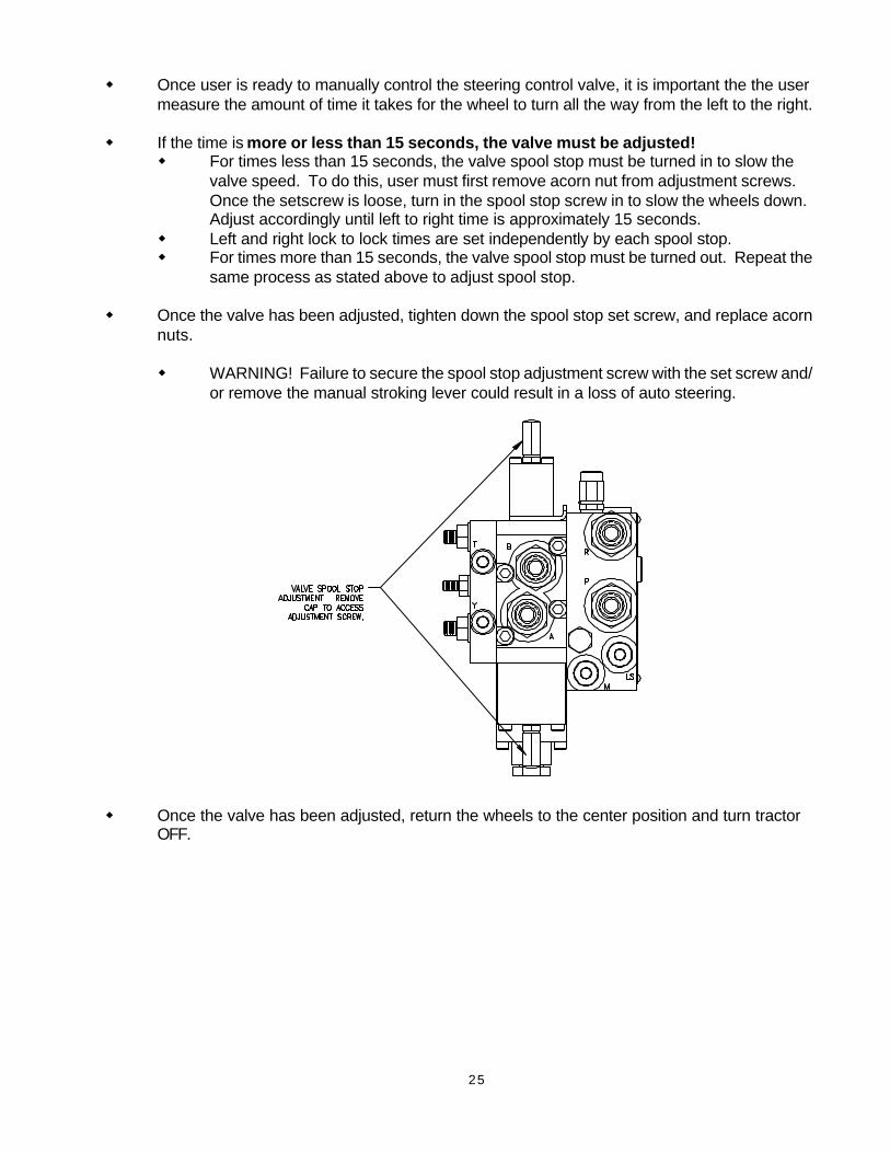
w Once user is ready to manually control the steering control valve, it is important the the usermeasure the amount of time it takes for the wheel to turn all the way from the left to the right.
w If the time is more or less than 15 seconds, the valve must be adjusted!w For times less than 15 seconds, the valve spool stop must be turned in to slow the
valve speed. To do this, user must first remove acorn nut from adjustment screws.Once the setscrew is loose, turn in the spool stop screw in to slow the wheels down.Adjust accordingly until left to right time is approximately 15 seconds.
w Left and right lock to lock times are set independently by each spool stop.w For times more than 15 seconds, the valve spool stop must be turned out. Repeat the
same process as stated above to adjust spool stop.
w Once the valve has been adjusted, tighten down the spool stop set screw, and replace acornnuts.
w WARNING! Failure to secure the spool stop adjustment screw with the set screw and/or remove the manual stroking lever could result in a loss of auto steering.
w Once the valve has been adjusted, return the wheels to the center position and turn tractorOFF.
26
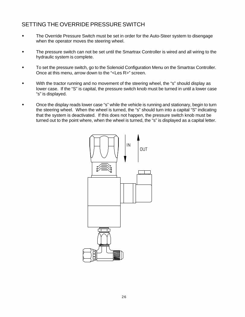
SETTING THE OVERRIDE PRESSURE SWITCH
w The Override Pressure Switch must be set in order for the Auto-Steer system to disengagewhen the operator moves the steering wheel.
w The pressure switch can not be set until the Smartrax Controller is wired and all wiring to thehydraulic system is complete.
w To set the pressure switch, go to the Solenoid Configuration Menu on the Smartrax Controller.Once at this menu, arrow down to the “<Les R>” screen.
w With the tractor running and no movement of the steering wheel, the “s” should display aslower case. If the “S” is capital, the pressure switch knob must be turned in until a lower case“s” is displayed.
w Once the display reads lower case “s” while the vehicle is running and stationary, begin to turnthe steering wheel. When the wheel is turned, the “s” should turn into a capital “S” indicatingthat the system is deactivated. If this does not happen, the pressure switch knob must beturned out to the point where, when the wheel is turned, the “s” is displayed as a capital letter.
27
Cable Connection and Routing
Overview of Cable Connection & RoutingSmartrax Loom Routing
Solenoid Cable Connection & RoutingSteering Position Sensor (SPS) Cable Connection and Routing
28
Overview of Cable Connection & Routing
Before starting the Cable Connection and Routing section of this document you should first ensurethat all components of the hydraulic steering kit are installed securely and neatly.
The cable connection and routing instructions that are included in this section consists of:
• Smartrax Loom connection and routing;
• Solenoid cable connection and routing
• Steering Position Sensor (SPS) cable connection and routing.
NOTE: The Cable Connection & Routing section of this manual is generic and has beendesigned to cover all tractor types currently available.
29
Smartrax Loom Routing
STEPS
1) Route the Smartrax Loom from the Valvetowards the tractor cab. It should lead into thetractor cab through a suitable entry point.
NOTE: Ensure Smartrax Loom is mountedneatly. Secure it (where possible) to existingpoints on the tractor using cable ties. Ensure itis not routed near heated areas such as theexhaust. Do not route it in close proximity tomoving parts.
KEY POINTS
NOTE: Ensure Smartrax Loom is securelyconnected to the Valve.
30
Solenoid Cable Connection & Routing
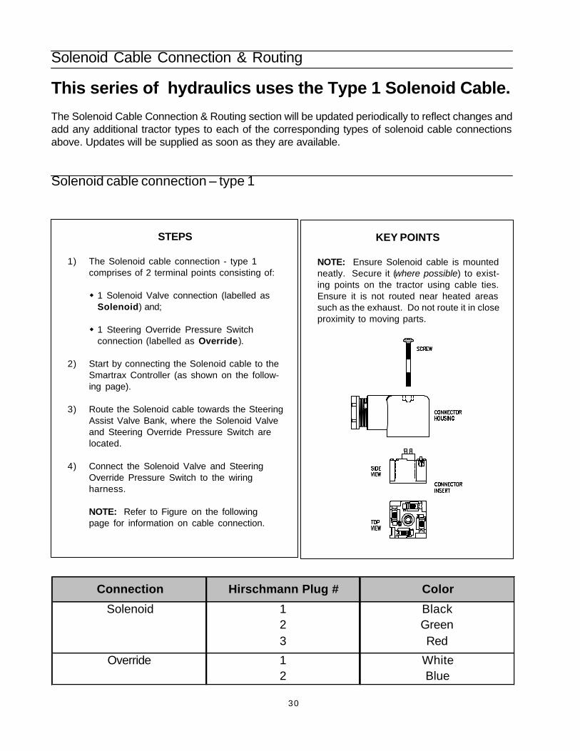
This series of hydraulics uses the Type 1 Solenoid Cable.
The Solenoid Cable Connection & Routing section will be updated periodically to reflect changes andadd any additional tractor types to each of the corresponding types of solenoid cable connectionsabove. Updates will be supplied as soon as they are available.
Solenoid cable connection – type 1
STEPS
1) The Solenoid cable connection - type 1comprises of 2 terminal points consisting of:
w 1 Solenoid Valve connection (labelled asSolenoid) and;
w 1 Steering Override Pressure Switchconnection (labelled as Override).
2) Start by connecting the Solenoid cable to theSmartrax Controller (as shown on the follow-ing page).
3) Route the Solenoid cable towards the SteeringAssist Valve Bank, where the Solenoid Valveand Steering Override Pressure Switch arelocated.
4) Connect the Solenoid Valve and SteeringOverride Pressure Switch to the wiringharness.
NOTE: Refer to Figure on the followingpage for information on cable connection.
KEY POINTS
NOTE: Ensure Solenoid cable is mountedneatly. Secure it (where possible) to exist-ing points on the tractor using cable ties.Ensure it is not routed near heated areassuch as the exhaust. Do not route it in closeproximity to moving parts.
Connection Hirschmann Plug # Color
1 Black2 Green
1 White2 Blue
Override
Solenoid
Red3
31
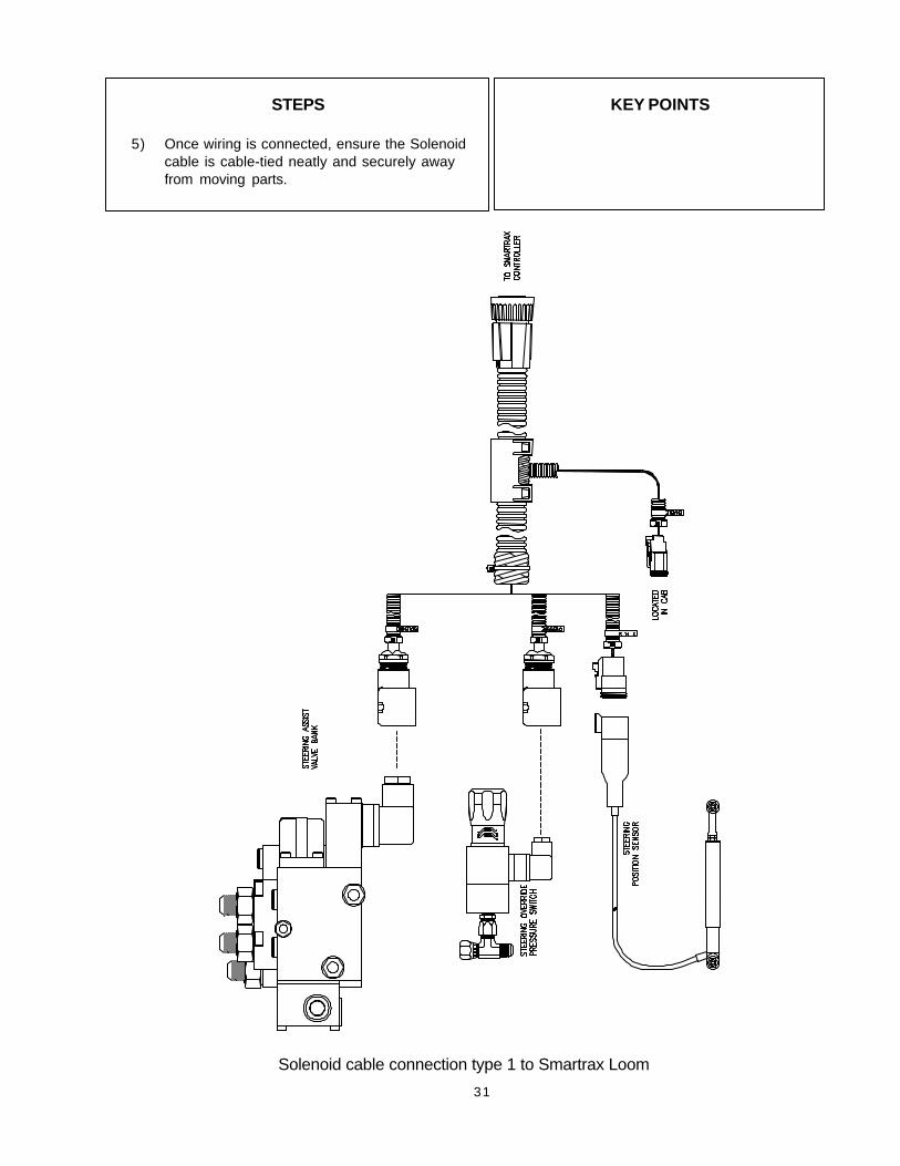
Solenoid cable connection type 1 to Smartrax Loom
STEPS
5) Once wiring is connected, ensure the Solenoidcable is cable-tied neatly and securely awayfrom moving parts.
KEY POINTS
32
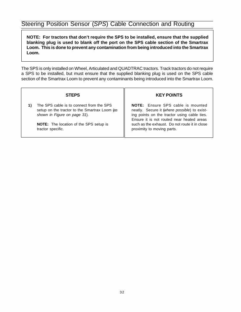
Steering Position Sensor (SPS) Cable Connection and Routing
The SPS is only installed on Wheel, Articulated and QUADTRAC tractors. Track tractors do not requirea SPS to be installed, but must ensure that the supplied blanking plug is used on the SPS cablesection of the Smartrax Loom to prevent any contaminants being introduced into the Smartrax Loom.
STEPS
1) The SPS cable is to connect from the SPSsetup on the tractor to the Smartrax Loom (asshown in Figure on page 31).
NOTE: The location of the SPS setup istractor specific.
NOTE: For tractors that don’t require the SPS to be installed, ensure that the suppliedblanking plug is used to blank off the port on the SPS cable section of the SmartraxLoom. This is done to prevent any contamination from being introduced into the SmartraxLoom.
KEY POINTS
NOTE: Ensure SPS cable is mountedneatly. Secure it (where possible) to exist-ing points on the tractor using cable ties.Ensure it is not routed near heated areassuch as the exhaust. Do not route it in closeproximity to moving parts.
RAVEN INDUSTRIES
LIMITED WARRANTY
WHAT IS COVERED?
This warranty covers all defects in workmanship or materials in your RavenFlow Control Product under normal use, maintenance, and service.
HOW LONG IS THE COVERAGE PERIOD?
This warranty coverage runs for 12 months from the purchase date of yourRaven Flow Control Product. This warranty coverage applies only to theoriginal owner and is not transferrable.
HOW CAN YOU GET SERVICE?
Bring the defective part, and proof of date of purchase, to your local dealer.If your dealer agrees with the warranty claim, he will send the part, andproof of purchase to his distributor or to Raven for final approval.
WHAT WILL RAVEN INDUSTRIES DO?
When our inspection proves the warranty claim, we will, at our option, repairor replace the defective part and pay for return freight.
WHAT DOES THIS WARRANTY NOT COVER?
Raven Industries will not assume any expense or liability for repairs madeoutside our plant without written consent. We are not responsible for damageto any associated equipment or product and will not be liable for loss ofprofit or other special damages. The obligation of this warranty is in lieu ofall other warranties, expressed or implied, and no person is authorized toassume for us any liability. Damages caused by normal wear and tear, mis-use, abuse, neglect, accident, or improper installation and maintenanceare not covered by this warranty.

RAVEN INDUSTRIES FLOW CONTROL DIVISION205 East Sixth Street - P.O. Box 5107 - Sioux Falls, South Dakota 57117-5107
E-mail: [email protected]
Toll-free: 800-243-5435 - Fax: 605-331-0426
Universal Hydraulic Steering Kit Installation Guide for Closed Centered, Load-Sensing Hydraulic Systems#016-9001-019 Rev A 04/05