Embed Size (px)
Citation preview
THTRMVMV
GND
FPHLOHLIPS
C
R
G
W
Y
EAC NHUM NXFMR NLINE NCIR N
IGNIND
IGN NIND N
HUMEAC
XFMRLINEPARKPARKHEATCOOL
IGNITOR
Y
W
G
R
THERMOSTAT
GASVALVE
HIGH LIMIT(N. C.)
ROLLOUT(N. C.)
AUX. HIGHLIMIT (N. C.)
PRESSURE SWITCH (N. O.)
FLAMESENSORPROBE
COMPRESSORCONTACTOR
ELECTRONICAIR CLEANER
HUMIDIFIER
INDUCER
CIRCULATORBLOWER
50A55
24 VAC
120 VAC
24 VAC CLASS IITRANSFORMER
HOT(LINE)
NEUTRAL(LINE)
TH TR
Low Voltage (24 VAC)
Line Voltage (120 VAC)
LEGEND
N. C. = Normally closed switchN. O. = Normally open switch
RO1
RO2
TYPICAL SYSTEM WIRING DIAGRAM
TWIN*TWIN*
50A55-843in other
furnace(s)—
TWINNINGAPPLICATIONS
ONLY
UNIVERSAL HOT SURFACEIGNITION CONTROLS (HSI)
WIRING ANDCONFIGURATION
Flame Current Requirements: Minimumcurrenttoinsureflamedetection.............1 µa DC➀ Maximum current for non-detection .....................0.1 µa DC➀ Maximumallowableleakageresistance ............. 100 M ohms Flame establishing time ......................0.8 seconds maximum Flame failure response time ...............2.0 seconds maximum➀MeasuredwithaDCmicroammeterintheflameprobelead
50A55-843
TEC
HN
ICA
L H
ELP
www.white-rodgers.com 195
HEAT delay-to-fan-off:
Set switch#3 #4
60 sec.90 sec.120 sec.180 sec.*
On OnOff OnOn OffOff Off
COOL delay-to-fan-off:
Set switch#1
45 sec.*90 sec.
OnOff
HEAT delay-to-fan-on:
Set switch#2
30 sec.*45 sec.
OnOff
OPTION SWITCH POSITIONS
* Factory setting
The 50A55-843 is an automatic gas interrupted ignition control that employs a microprocessor to continually monitor, analyze, and control the proper operation of the gas burner, inducer, and fan.Signals interpreted during continual surveillance of the ther-mostatandflamesensingelementinitiateautomaticignitionoftheburner,sensingoftheflame,andsystem shut-off during normal operation.
OPTION SWITCHES The option switches on the 50A55-843 control are used to determine the length of the cool delay-to-fan-off, heat delay-to-fan-on and heat delay-to-fan-off periods. The following table shows the time periods that will result from the various switch positions.
HEAT MODE In a typical system, a call for heat is initiated by closing the thermostat contacts. This starts the 50A55 control’s heating sequence.Theinducerblowerandoptionalhumidifierareenergized and the ignitor is powered within one second.
Thiscontrollerhasanadaptivealgorithmthatadjuststhedu-ration of the ignitor warm-up, to extend ignitor life. Upon initial application of power, the warm-up time is 17 seconds. The ignitor on-time will then be increased or decreased depend-ingonwhetherornotflameisachieved.Thewarm-uptimeislimitedtoamaximumof21seconds.Duringthefirst64warm-up periods following power-up, the warm-up time may not be less than 17 seconds.Uponacallforheat,ifthewarm-uptimehasnotbeenlocked,it will be decreased by one second. This reduction of the ignitoron-timewillcontinueuntilflamefailstobeachieved(resulting in a retry).In the event of a retry, the warm-up time will be increased by twosecondsandlockedinatthatduration.Oncethewarm-uptimeislocked,itremainsfixeduntilanothercallforheatresults in a retry, in which case the warm-up time is again increasedbytwosecondsandremainslocked.In the event of two successive retry attempts, the warm-up timewillbeunlockedandsetto21seconds.Ifflameisthenachieved, the warm-up time will begin adapting again with the next call for heat. If, however, this third attempt fails to achieveflame,thecontrolwillgointosystemlockout.At the end of the ignitor warm-up time, both valves in the 36E manifold gas valve are opened. Flame must be detected within 4 seconds. Seeinstallationinstructionsformoresystemsequencedetail.
COOL MODE In a typical system, a call for cool is initiated by closing the thermostat contacts. This energizes the 50A55 control and the compressor. The cool delay-to-fan-on period begins. After the delay period ends, the optional electronic air cleaner is energized, and the circulator fan is energized at cool speed. Afterthethermostatissatisfied,thecompressorisde-energized and the cool mode delay-to-fan-off period begins. After the delay-to-fan-off period ends, the circulator fan and electronic air cleaner (optional) are de-energized.MANUAL FAN ON MODE If the thermostat fan switch is moved to the ON position, the circulator fan (cool speed) and optional electronic air cleaner are energized. When the fan switch is returned to the AUTO position, the circulator fan and electronic air cleaner (optional) are de-energized.SYSTEM LOCKOUT FEATURES Whensystemlockoutoccurs,thegasvalveisde-energized,thecirculatorblowerisenergizedatheatspeed,and,ifflameis sensed, the inducer blower is energized. The diagnostic indicatorlightwillflashorglowcontinuouslytoindicatesystem status. (System lockout will never override the precautionary features.)
To reset the control after system lockout, do one of the following:1. Interrupt the call for heat or cool at the thermostat for at
leastonesecondbutlessthan20seconds(ifflameissensed with the gas valve de-energized, interrupting the call for heat at the thermostat will not reset the control).
2. Interrupt the 24 VAC power at the control for at least one second.Youmayalsoneedtoresettheflamerolloutsensor switch.
3. Afteronehourinlockout,thecontrolwillautomaticallyreset itself.
DIAGNOSTIC FEATURES The 50A55-843 control continuously monitors its own operation and the operation of the system. If a failure occurs, the LED will indicate a failure code as shown below. If the failure is internal to the control, the light will stay on continuously. In this case, the entire control should be replaced, as the control is not field-repairable.
If the sensed failure is in the system (external to the control), theLEDwillflashinthefollowingflash-pausesequencestoindicatefailurestatus(eachflashwilllastapproximately0.25seconds, and each pause will last approximately 2 seconds).1flash,thenpause Systemlockout2flashes,thenpause Pressureswitchstuckclosed3flashes,thenpause Pressureswitchstuckopen4flashes,thenpause Openlimitswitch5flashes,thenpause Openrolloutswitch6flashes,thenpause 115VoltACpowerreversed/
Improper ground7flashes,thenpause LowflamesensesignalContinuousflashing Flamehasbeensensedwhen (nopause) noflameshouldbepresent(no call for heat)TheLEDwillalsoflashonceatpower-up.
UNIVERSAL HOT SURFACEIGNITION CONTROLS (HSI)
WIRING ANDCONFIGURATION
www.white-rodgers.com196
TEC
HN
ICA
L H
ELP
UNIVERSAL HOT SURFACEIGNITION CONTROLS (HSI)
WIRING ANDCONFIGURATION
50A55TERMINAL
TERMINALTYPE
SYSTEM COMPONENTCONNECTION
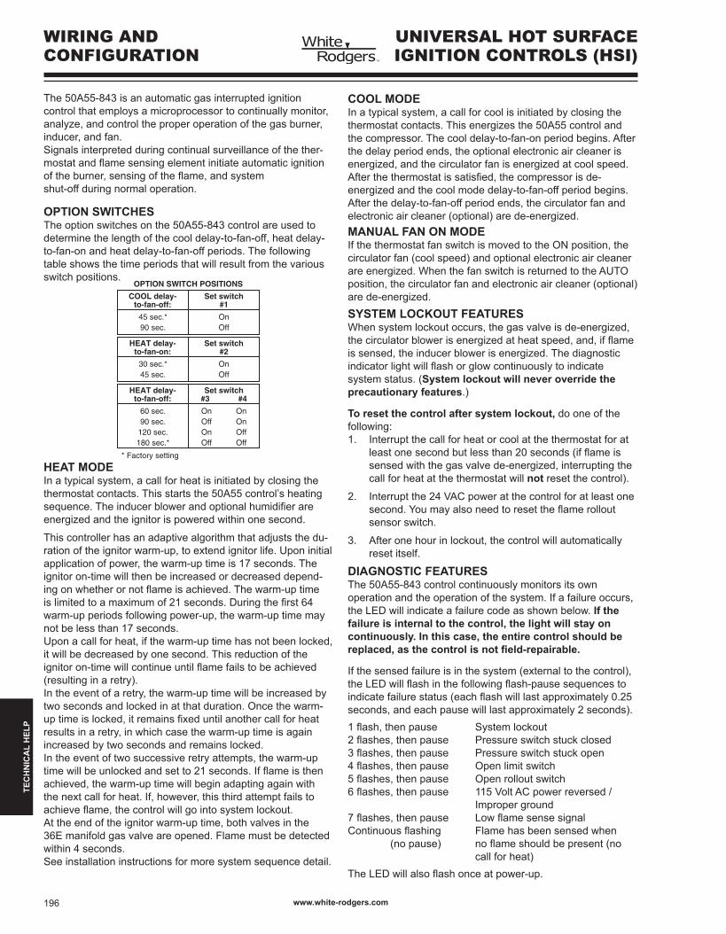
TYPICAL SYSTEM WIRING TABLE
W
G
R
Y
C
TWIN*
MV (2 terminals)
TR
TH
RO1
RO2
FP
PS
HLI
HLO
GND
(unused terminal)
IND
IGN
IND N
IGN N
COOL
HEAT
PARK (2 terminals)
LINE
XFMR
EAC (optional)
HUM (optional)
CIR N
LINE N
XFMR N
EAC N (optional)
HUM N (optional)
Terminal
block with
captive
screws
12-pin
connector
& harness
4-pin connector & harness
spade terminal
spade terminal
spade terminal
spade terminal
spade terminal
spade terminal
spade terminal
spade terminal
spade terminal
spade terminal
spade terminal
spade terminal
low voltage thermostat W terminal (or equivalent)
low voltage thermostat G terminal (or equivalent)
low voltage thermostat R terminal (or equivalent)
low voltage thermostat Y terminal (or equivalent)
(2nd wire from Y terminal goes to 24 VAC HOT side of
compressor contactor coil)
24 VAC COMMON side of compressor contactor coil
one wire twinning terminal
gas valve (both gas solenoids are connected in parallel)
24 VAC transformer (low voltage COMMON side)
24 VAC transformer (low voltage HIGH side)
rollout switch OUTPUT
rollout switch INPUT
flame sensor probe*
pressure switch INPUT
high limit INPUT
high limit OUTPUT
MUST BE RELIABLY GROUNDED TO CHASSIS
inducer HOT side
ignitor HOT side
inducer NEUTRAL side
ignitor NEUTRAL side
circulator blower COOL SPEED terminal
circulator blower HEAT SPEED terminal
unused circulator blower terminals
input voltage (120 VAC) HOT side
24 VAC transformer line voltage HOT side
electronic air cleaner HOT side
humidifier HOT side
circulator blower NEUTRAL terminal
input voltage (120 VAC) NEUTRAL side
24 VAC transformer line voltage NEUTRAL side
electronic air cleaner NEUTRAL side
humidifier NEUTRAL side
* The twinning feature is available only on models with six screw terminals; one of these terminals will be designated “TWIN”. All 50A55-843 controls used in twinning applications must have the “TWIN” terminal.
† Maximum recommended flame probe wire length is 36 inches.
The 50A55 has only one serviceable part–an automotive type fuse, which protects the low voltage transformer from damage if its output is short-circuited. If the fuse has opened up, remove whatever caused the short circuit and replace the fuse with only a 3 Amp automotive type fuse. If the fuse is not the cause of the control’s problem, replace the entire 50A55 control. There are no other user serviceable parts.Additionaljumperwiresareincludedinthispackageandshould be used if the original wiring does not reach the control after mounting. Refer to the furnace wiring diagram for proper connection of the wires.
An additional wiring harness (WR 115-0223) is included inthispackage.Ifthecontrolbeingreplacedhasa2-pin(inducer / ignitor) connector, this wiring harness will adapt the furnace wiring to the 4-pin connector of the replacement control.Trane application - Jumper wire 151-2906 (provided with control) must be installed on the furnace from R01 to R02 of the 12-pin connector.
TEC
HN
ICA
L H
ELP
www.white-rodgers.com 197


![11 DEPARTMENT OF DEFENCE AND MILITARY VETERANS (DOD&MV) (DEFENCE SECRETARIAT [DEF SEC] AND SOUTH AFRICAN NATIONAL DEFENCE FORCE [SANDF]) ANNUAL PERFORMANCE](https://img.pdfslide.us/doc/110x75/56649f445503460f94c64bc0/11-department-of-defence-and-military-veterans-dodmv-defence-secretariat.jpg)