Embed Size (px)
Citation preview

(12) United States Patent Ames et al.
(io) Patent No.: (45) Date of Patent:
US 7,095,504 B1 Aug. 22,2006
(54) APODIZATION OF BEAMS IN AN OPTICAL INTERFEROMETER
(75) Inventors: Lawrence L. Ames, San Jose, CA (US); Kalyan Dutta, Los Altos Hills, CA (US)
(73) Assignee: Lockheed Martin Corporation, Bethesda, MD (US)
Subject to any disclaimer, the term of this patent is extended or adjusted under 35 U.S.C. 154(b) by 311 days.
( * ) Notice:
(21) Appl. No.: 10/788,166
(22) Filed: Feb. 25, 2004
Related U.S. Application Data
(60) Provisional application No. 601449,995, filed on Feb. 25, 2003.
(51) Int. C1.
(52) U.S. C1. ....................................... 356/498; 3561486 (58) Field of Classification Search ................ 3561486,
3561487,493,498, 500, 450
GOlB 9/02 (2006.01)
See application file for complete search history.
(56) References Cited
U.S. PATENT DOCUMENTS
4,514,850 A 4/1985 Holmes et al 5,090,803 A 2/1992 Ames et al. 5,291,570 A 3/1994 Filgas et al. 5,452,392 A 9/1995 Baker et al. 6,483,982 B1 11/2002 Takahashi
6,646,723 B1 11/2003 Dubovitsky et a1 6,710,880 B1 3/2004 Zhao
FOREIGN PATENT DOCUMENTS
wo WO 3021319 A2 3/2003
OTHER PUBLICATIONS
US. Appl. No. 10/787,662, filed Feb. 25, 2004, Ames et al. US . Appl. No. 10/349,758, filed Jan. 22, 2003, Ames et al. US . Appl. No. 10/293,209, filed Nov. 12, 2002, Ames et al. US . Appl. No. 10/180,086 filed Jun. 27, 2002, Ames et al. Ames, Lawrence, et al., “SIM external metrology beam launcher (QP) development,” Lockheed Martin Advanced Technology Ctr./ Lockheed Martin Jet Propulsion Lab, SPIE Conference, Kona Hawaii, 2002 [4852-551. Halverson, Peter G., et al., “Techniques for the Reduction of Cyclic Errors in Laser Metrology Gauges for the Space Interferometry Mission,” presented at American Society for Precision Engineering ASPE’s 16th Annual Meeting, Nov. 10-15, 2001. Zhao, Feng, et al. “Development of Sub-nanometer Racetrack Laser Metrology for External Triangulation Measurement for the Space Interferometry Mission”, presented at American Society for Preci- sion Engineering ASPE’s 16th Annual Meeting, Nov. 10-15, 2001.
Primary Examiner--Gregory Toatley Assistant Examiner-Marissa J Detschel (74) Attorney, Agent, or Firm-McDermott Will & Emery LLP
(57) ABSTRACT
An interferometry apparatus comprises one or more beam generators, a detector, and a plurality of optical paths along which one or more beams of light propagate. Disposed along at least one of the optical paths is an apodization mask to shape one of the beams.
34 Claims, 12 Drawing Sheets
U.S. Patent Aug. 22,2006 Sheet 1 of 12
I
US 7,095,504 B1
1 ; * A- e cy h
m
e 2 h
f 0 0 m
U.S. Patent Aug. 22,2006 Sheet 2 of 12 US 7,095,504 B1
U.S. Patent Aug. 22,2006 Sheet 3 of 12 US 7,095,504 B1
ci a c3
10.5i0.5mm 162, \ 1 6 4 7
334
I REFLECTIVE ’ ABSORPTIVE UNCOATED APODIZED
1
I I I I
I I I REFLECTIVE I ABSORPTIVE UNCOATED APODIZED
I I I 0
CI
I I I I I I I . .
I I I I I ,, 100% (REFLECTIVE) h)
(A BSO R PT I v E)
I I I I I I
I I I
I I I I I I I I I I I I I
I I I I I I I I I I I I I I I I
I I I I I I I I
I I I I I I I
(REFLECTIVE)------ (ABS0 RPTl VE) I
I I I I I I I 0% 0%
I I I I I I DISTANCE [mm] I I t
2 ~~~~$ ON MINOR AXIS --e4
COSiNE I I I 1 1 1 I FROM CENTER I I 1
O t o 4 0 \o VI VI 0 P
U
U
FIG. 3B w Y
U.S. Patent Aug. 22,2006 Sheet 5 of 12 US 7,095,504 B1
LL
U.S. Patent Aug. 22,2006 Sheet 6 of 12
.. 2
US 7,095,504 B1
I I
h
Q h
U
2 h
e cy h h
e 2 h
f 0 0
104
'. I \
122a
FIG. 5
502
- 102a I
102b 1
I12a
rind LL I
4 0 \o VI VI 0 P
U
U
w Y
U.S. Patent Aug. 22,2006 Sheet 8 of 12 US 7,095,504 B1
U.S. Patent Aug. 22,2006 Sheet 9 of 12 US 7,095,504 B1
102a FIG. 7A
U.S. Patent Aug. 22,2006
0 .- E
Sheet 10 of 12 US 7,095,504 B1
0 cy h h h h
E E
0 , 9 U
0 0
U.S. Patent Aug. 22,2006
z I- W Dz
c v, W I- O c
I- W
I- v, W c
z
0 E
/ /
/
Sheet 11 of 12 US 7,095,504 B1
I’
/’
U.S. Patent Aug. 22,2006
Radii of Apodizers [in mm]
i I
I I
I I I I I I I I \ \ \ \ \ \ \ \ \ \ \ \ \
820
Sheet 12 of 12 US 7,095,504 B1
842c 32c
842d
Rodii of Guard bands 2 [in mm] pr
' \ \ \ \
I t
00
N C V 44
i \ \
I
I 1 /
/
0
pr) 0
0 Q, N
FIG. 88
US 7,095,504 B1 1
APODIZATION OF BEAMS IN AN OPTICAL INTERFEROMETER
CROSS-REFERENCES TO RELATED APPLICATIONS
The present invention claims priority to U.S. Provisional Application No. 601449,995, filed Feb. 25, 2003 and is herein incorporated by reference for all purposes.
The present invention is related to the following com- monly owned, co-pending applications: U.S. application Ser. No. 101180,086, filed Jun. 27, 2002), U.S. application Ser. No. 101349,758, filed Jan. 22, 2003), U.S. application Ser. No. 101293,209, filed Nov. 12, 2002), and U.S. appli- cation Ser. No. 101787,662, concurrently filed herewith, entitled “A Symmetric Periscope, Concentric Beam Con- figuration for an Ultra-high Precision Laser Interferometric Beam Launcher”, each of which are herein incorporated by reference for all purposes.
STATEMENT AS TO RIGHTS TO INVENTIONS MADE UNDER FEDERALLY SPONSORED
RESEARCH OR DEVELOPMENT
The U.S. Government has a paid-up license in this inven- tion and the right in limited circumstances to require the patent owner to license others on reasonable terms as provided for by the terms of NASA SIM Prime Contact No. NAS7-1407 awarded by the National Aeronautics and Space Administration (NASA).
BACKGROUND OF THE INVENTION
The present invention relates generally to interferometry and in particular to improved performance of interferometry by the patterning or otherwise shaping of one or more beams in an interferometric device.
Precision laser interferometry can be used to precisely determine (or monitor changes of) the distance to one or more fiducial points, such as a flat mirror, rooftop mirror, or corner-cube retro-reflector (“retro”), or between such fidu- cial points. An interferometer generally is composed of three components or subsystems: (1) a radiation source (e.g., a laser device or some other suitable beam generator), (2) an optics component for producing beams of light for reference, measurement, and so on (also referred to as a “beam launcher”), and (3) a signal processor (e.g., an observer or a photo-detector and associated electronic circuits) or other processing component to perform the interferometric deter- minations. In some configurations, the photo-detector is included in the optical component (beam launcher), while much of the supporting electronics (e.g., the phase meter(s) and computer) remain with the signal processor. As can be appreciated other subsystem configurations are possible.
Interferometers can be configured to operate in a number of ways. The present invention is applicable to optical interferometers in general, operating in the regions of the electromagnetic spectrum commonly referred to as the infra- red (IR) light region, visible light region, and ultra-violet (W) light region. Since there are many configurations of optical interferometers, only a small sampling of interfer- ometer configurations will be discussed for background purposes. It will therefore be understood that a “beam” in the context of the present invention can be IR, visible light, or W.
Some interferometers monitor the distance between two retros by directing a single beam towards a first one of the
5
10
15
20
25
30
35
40
45
50
55
60
6 5
2 retros. The single beam hits the first retro at a point that is offset from a vertex of the retro. The retro-reflected beam emerges from the first retro at a symmetrically located offset point, and the beam then is directed to a second retro. The beam and retros are positioned and aligned such the reflected beam hits the second retro also offset from the vertex, with the emerging beam doubly reflected back to an entrance point on the launcher. Such a circuitous configuration is sometimes referred to as a “racetrack” configuration.
Precision laser interferometry can be carried out in at least two modes, namely, the “homodyne” mode or the “hetero- dyne” mode. Either mode can be used for either the race- track configuration.
In the homodyne mode, a beam launcher splits a laser beam of a single frequency into two beams. One beam is directed out to the fiducial(s) to measure the distance. Upon returning to the beam launcher, the beam is aligned and collocated (and the polarization aligned, if needed) with the other portion of the original beam, and the resulting com- bined beam is directed onto a photo-detector. If the extra distance traveled by the measurement beam is an integer multiple of half the laser wavelength, then, when recom- bined, the two beams are in phase and add constructively, resulting in an increased signal from the photo-detector. If the measurement beam is an odd multiple of a quarter of the wavelength longer, the beams add destructively, resulting in a reduced signal from the photo-detector. If the distance between the retros changes, the signal fluctuates, and the fluctuations in the signal give a measure of the relative motion of the retros. A signal processor (e.g., an observer or a photo-detector and electronic circuit) “counts fringes” to determine the change in distance between the retros relative to an initial distance. The resolution of a homodyne inter- ferometer is limited, as it is difficult to measure changes in distance significantly smaller than the laser wavelength (typically a half to several micrometers) due to intensity fluctuations of the laser.
A heterodyne interferometer configuration uses two beams that are offset in frequency to slightly different frequencies. Typically, the beams originate from a single laser. The difference between the frequencies is chosen to be convenient for detectors and electronics. Typically, the fre- quency difference is in the range of about 10 liHz to about 100 MHz. Typically, one frequency-offset laser beam (the “measurement beam”) emanates from the beam launcher to interrogate the distance to the retro(s) while the second frequency-offset laser beam (the “local oscillator” or LO) beam remains internal to the beam launcher. When the measurement beam and the LO beam are aligned, collo- cated, and with aligned polarizations, and are directed onto the photo-detector, the photo-detector produces a “beat” signal. By comparing this beat signal to the known differ- ence of frequency offsets between the laser beams, it is possible to track changes in the relative phase of the signal to find the change in retro distance relative to the initial value. With precision phase meters, it is possible to resolve distances to small fractions of the laser wavelength, result- ing in measurements with sub-nanometer precision.
When measuring distances with fine precision, various error sources can affect the results. The laser intensity can fluctuate. The laser radiation is often routed to the beam launcher by means of optical fibers, where small effects such as a temperature variation or a strain on the fiber can affect the apparent optical length of the fiber and can result in a phase change that erroneously appears to be a measured displacement of the fiducial points. These errors can be reduced by replacing the “known difference” of the laser
US 7,095,504 B1 3
frequency offsets with a “reference signal” that measures the frequency difference directly. This reference signal is cre- ated by mixing a portion of the LO beam with the “reference beam”, which is a portion of the first laser beam that does not interrogate the distance between retros, and directing the combined beam onto a second photo-detector. The use of a reference beam significantly reduces the errors introduced by any common element (e.g., laser or fiber), but it cannot correct for elements that are unique to the measurement path or the reference path. Other errors can be reduced by sharing elements between the measurement and LO beams. The measurements are not affected by elements in the beam-path “downstream” from the point where the two laser beams are first combined (the point where they become aligned, like- polarized, and collocated), as the elements are common to both beams.
In the optical component referred to as the beam launcher, the various beams of light are bent in different directions (e.g., by the use of reflecting surface such as mirrors) and made to pass through various openings formed in the beam launcher. The diffraction of light that results when a wide beam of light passes through an opening that is narrower than the beam width is generally an undesirable artifact. When such a diffracted beam propagates a distance, the fringing effect becomes more pronounced. These optical artifacts may result in cross-talk if light rays from different beams go to the wrong detector channels, thus giving rise to “cyclic error” that can result in erroneous distance determi- nations. It is possible to model these diffractive affects and to introduce masks that reduce the effect, as disclosed in U.S. application Ser. No. 101293,209, for example. How- ever, it may be necessary to mask out more of the beam than is desirable from the point of view of laser power conser- vation.
Additionally, a beam may hit an optic surface at its edge (e.g., a hole in a separation mirror). It is difficult to maintain adequate mirror surface quality immediately adjacent to an edge. There are often chips in the surface, bevels, or other surface irregularities. These artifacts can also result in diffraction artifacts.
BRIEF SUMMARY OF THE INVENTION
The present invention comprises an optical interferometer device having one or more apodization masks disposed along optical paths in the device. An aspect of the invention is the use of one or more apodization masks to shape one or more beams to produce shaped beams as needed. A shaped beam can include a first beam portion having apodized edges to reduce diffraction during propagation over a distance. The shaped beam can include a shadow region between first and second beam portions. The shadow region can correspond to the shape of an edge of a optic element so that the edge can be enveloped by the shadow region when the shaped beam is transmitted to the optic element, thus avoiding diffraction that might arise from surface defects at the edge.
BRIEF DESCRIPTION OF THE DRAWINGS
The present invention is described in further detail by way of illustrative embodiments as shown in the following figures, wherein:
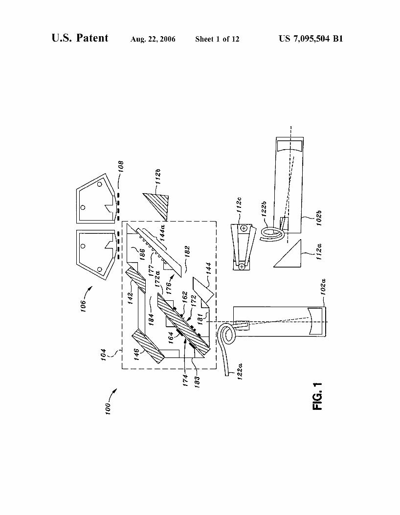
FIG. 1 is a simplified schematic showing an illustrative embodiment of an interferometer according to the present invention;
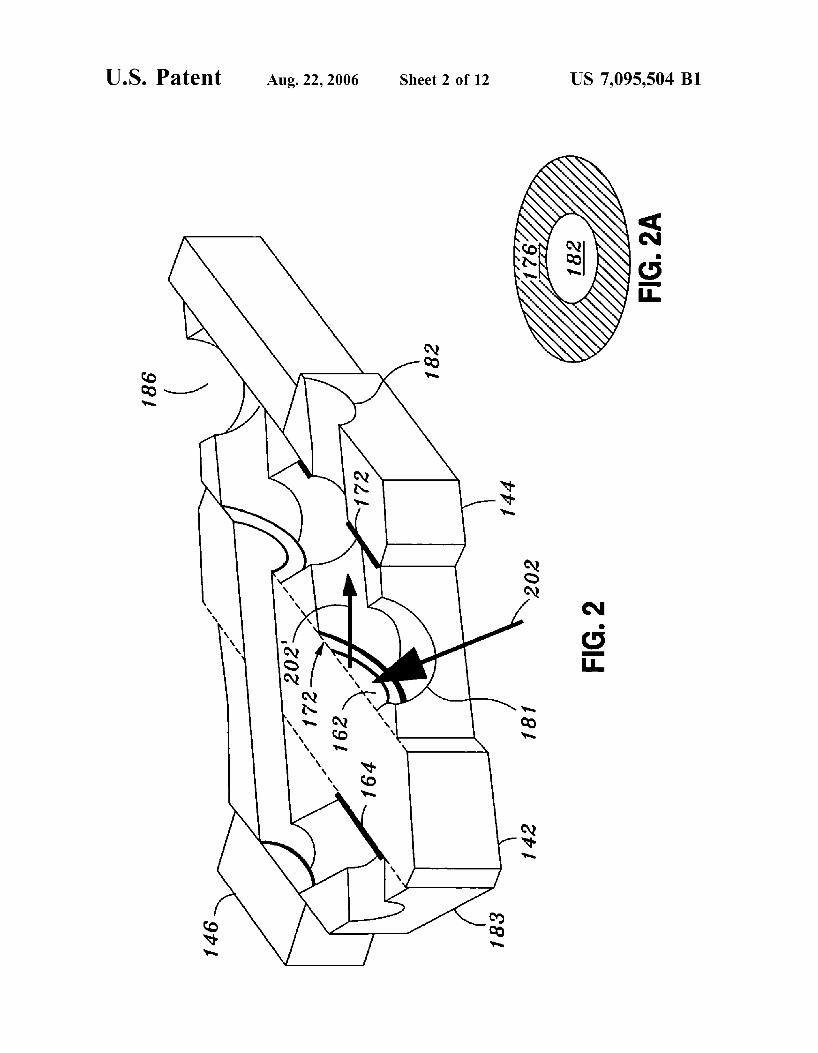
FIG. 2 is a cutaway view of the optical component (beam launcher) component shown in FIG. 1;
4 FIG. 2A shows a projected view as seen along the
direction of the reflected source beam 202’ shown in FIG. 2; FIG. 3A compares the performance of apodization masks
versus hard edges; FIG. 3B illustrates the apodization masks shown in FIG.
1; FIGS. 4A-4C illustrate various apodization mask place-
ments; FIG. 4D illustrates an alternative embodiment of the
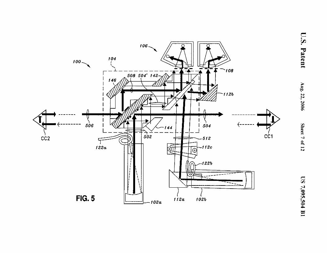
i o device shown in FIG. 1; FIG. 5 shows the optical paths of the interferometer
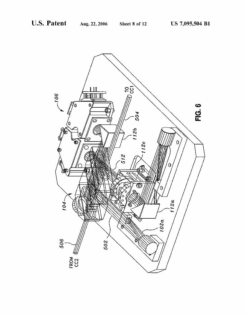
configuration shown in FIG. 1; FIG. 6 is a screen shot of a solid-model rendering of the
interferometer of FIG. 5, produced by a solid-modeling
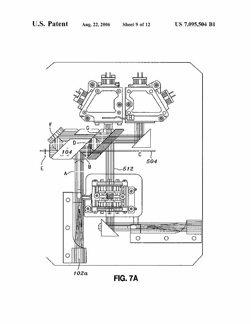
FIGS. 7A and 7B show beam intensity profiles along various points in the optical paths shown on a top view solid-model rendering of the interferometer of FIG. 5;
FIGS. SA and 8B illustrate another apodization mask
FIG. 9 shows yet another apodization mask pattern.
5
15 program, isometric view;
20 configuration; and
DETAILED DESCRIPTION OF THE INVENTION
25 The following description of the present invention is
presented with respect to a specific interferometer device that was under study at the time of the invention. However, it will be clear to one of ordinary skill, from the following
30 discussion, that the present invention can be adapted for use in any kind of optical interferometer.
FIG. 1 shows the basic components of an optical inter- ferometer in the context of a specific illustrative embodi- ment. The interferometer configurations that is shown in the
35 figure is known as a “common path heterodyne interferom- eter” (CoPHI). The CoPHI interferometer shown in FIG. 1 operates is arranged in a “racetrack” (RT) configuration. A source beam directed to the optical component 104 is provided by a collimator 102a. In the specific embodiment
40 shown, the collimator 102a is an off-axis parabolic collima- tor. This component is described in more detail in U.S. application Ser. No. 101349,758. It can be appreciated of course that any other suitable device for the collimator 102a can be used, and that the collimator shown in the figure is
45 shown merely as an illustrative example of a device that produces a beam that enters the optical component 104.
For heterodyne mode operation, a second collimator 102b is provided. In the specific embodiment shown, the second collimator is also an off-axis parabolic collimator. As with
50 collimator 102a, any other suitable device for the collimator 102b can be used.
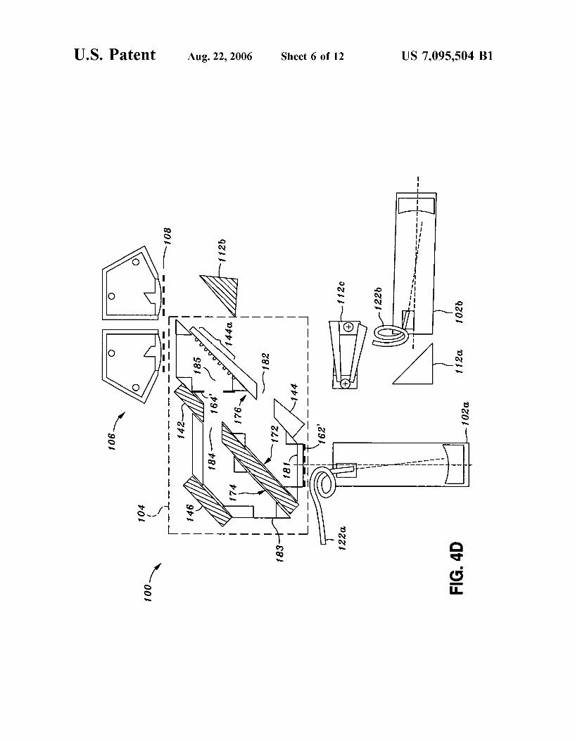
An optical component 104 collectively referred to herein as the beam launcher receives and directs the source beams produced by collimators 102a and 102b. The optical com-
55 ponent (beam launcher) 104 comprises various optic sur- faces and openings to define optical paths with the compo- nent. The openings are identified by the reference numerals 181-186. The surfaces of the optical component 104 include reflective surfaces 172,174 of a double-sided mirror 142. An
60 opening 184 is provided in the double-sided mirror 142 and a reflective surface 172a having an opening is aligned with opening 184. A mirror 144 is provided with an opening 182 and a reflective surface 176 having an opening aligned with the opening 182. The mirror 144 includes a beam combining
65 segment 144a that is semitransparent and includes a diffrac- tion grating 177. The optical component 104 also includes a fold mirror 146. In the embodiment described herein, the
US 7,095,504 B1 5
reflective surfaces comprise layers ofAu (gold) deposited by known thin film deposition methods. It can be appreciated that the reflective surfaces can be produced with other materials and using other fabrication techniques. Disposed on the reflective surface 172 is a first apodization mask 162. A second apodization mask 164 is disposed relative to the reflective surface 174.
To complete the discussion of FIG. 1, additional optics include fold mirrors 112a and 112b to direct the light produced by the collimator 102b to one of the photodetec- tors of a dual detector component 106. A pair of shallow wedge prisms form a “Risley pair” (Risley prism) 112c for increased precision alignment. The opening 186 of the optical component 104 is aligned with the other photode- tector. The photodetector 106 comprises known processing electronics such as detectors, pre-amps, phase meters, and so on to perform interferometric measurements. A mask 108 is provided at the entrances to each of the photodetectors of the dual detector component 106. The mask is to help reduce signal cross-talk, a cause of cyclic error. Additional detail of the mask 108 is provided in U.S. application Ser. No. 101293,209, filed Nov. 12, 2002.
Additional detail of the optical component (beam launcher) 104 is provided in a concurrently filed, commonly owned U.S. application Ser. No. 601449,993 entitled “A Symmetric Periscope, Concentric Beam Configuration for an Ultra-high Precision Laser Interferometric Beam Launcher”. The cutaway view of the optical component 104 shown in FIG. 2 is provided for purposes of explaining the present invention. A source beam 202 enters the opening 181 and is reflected off of the reflecting surface 172, which is shown in FIG. 2 with apodization mask 162. The reflected beam 202’ is then directed along the path shown by the arrow toward the mirrored opening comprising the reflecting sur- face 176 and opening 182.
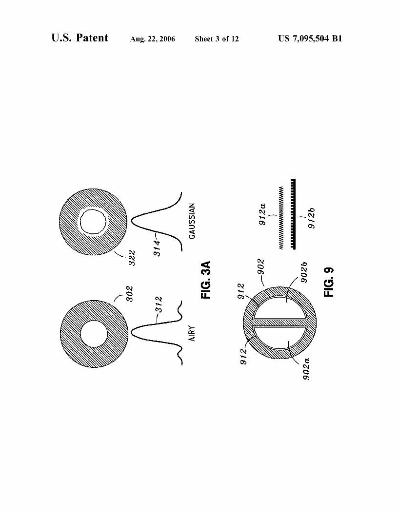
Refer for a moment to the diagrams shown in FIG. 3A. When a Gaussian beam of light passes through an aperture 302 that is smaller than the beam diameter, the Gaussian beam will be clipped by the hard edge of the aperture. Similarly, a beam reflected from a reflective surface that is smaller than the incident beam will be clipped. The clipping will create an intensity profile 312, such as an Airy fringe pattern, due to diffraction effects. As the beam propagates over a distance, the diffraction effects worsen. However, if a beam is shaped by a mask having a Gaussian or other similar soft, apodized edge, the resulting shaped beam can then be directed to the aperture 302 to produce an exit beam that exhibits a near-Gaussian intensity profile 314 having greatly reduced, or none, of the diffraction artifacts of the Airy-like profile 312. As an observation, a beam reflected from a surface that is narrower than the incident beam width will exhibit an Airy intensity profile as well. It is noted that while the beams shown are roughly Gaussian, this is not a requirement. Nonetheless, the problems presented by a hard edge of a transmissive or reflective surface may still apply.
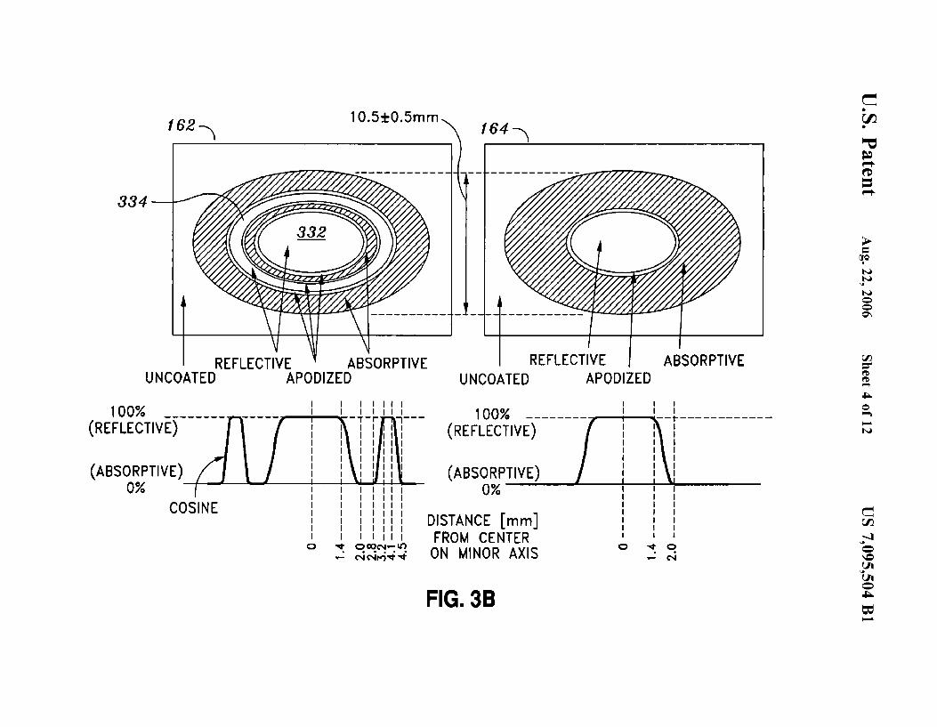
Returning to FIG. 2, it can be seen, therefore, that if the reflecting surface 172 did not have the apodization mask 162, then the reflected source beam 202’, as it passed through the opening 182, would exhibit an intensity profile such as the Airy fringe pattern shown in FIG. 3A. However, in accordance with this specific embodiment of the present invention, a first apodization mask 162 having the pattern shown in FIG. 3B is provided on surface 172. A second apodization mask 164 having the pattern shown in FIG. 3B is provided on reflective surface 174.
The purpose of the apodization masks (also, referred to as “optical apodizers”) is to take a wide high quality wave-
6 front-corrected beam (e.g., the beam from the first collimator 102a, FIG. 1) and excise a narrower, well-mannered, quasi- Gaussian-shaped beam which possesses diffraction rings of acceptably low intensity that would contribute negligibly to
5 instrument noise. Since the mirrored opening (182, 176) is on an angle (in this case a 45” angle) with respect to the incident beam 202’, the mirrored opening appears as an elliptical annulus surrounding an elliptical opening, as illus- trated in FIG. 2A. Therefore, the pattern of the apodization
As can be seen in FIG. 3B, the pattern for the apodization mask 162 comprises concentric areas of reflective and absorptive regions, with apodized regions formed between the reflective and absorptive regions. This particular mask
l5 pattern is adapted for improving cross-talk performance by improving spatial separation in concentric interferometer configurations, such as the configuration such as the “com- mon path heterodyne interferometer” (CoPHI) of FIG. 1.
Returning to FIG. 3B, the intensity profile of a beam shaped by the apodization mask 162 is shown in the chart below the pattern for the apodization mask. The concentric arrangement matches the mirrored opening (182,176) of the beam splitter. Thus, when source beam 202 is directed to the
25 apodized surface (162, 172), a central reflective region 332 of the apodization mask 162 reflects a core portion of the apodized source beam 202. The core portion has a Gaussian- like intensity profile and is smaller in breadth than the opening 182. Its edge is apodized and thus it’s intensity
3o quickly approaches zero toward the edge. Consequently, when the core portion passes through the opening 182 there is little or no diffraction.
An annular reflective region 334 of the apodization mask 162 reflects an annular portion of the apodized source beam
35 202 toward the reflective surface 176. The annular portion also exhibits a Gaussian-like intensity profile, having apodized inner and outer edges. Thus, the intensity approaches zero at both the inner and the outer edges of the annular portion. In addition, an annular shaped shadow
40 region between core portion and the annular portion forms a shadow that envelopes the edge of the opening 182 so that substantially none of the light from the source beam 202 will fall on the edge. Consequently, there is substantially no formation of diffraction patterns or other diffractive artifacts
45 that might arise due to surface defects common in optics near edges. The apodization mask 162 also shapes the core portion of the source beam, giving the beam a “fuzzy” (apodized) edge that propagates over distance with less diffraction. Thus in general, an apodization mask can be
50 patterned to produce a shaped beam that contains beam portions which have apodized edges so that those beam portions can propagate over a distance with less diffraction. Equally significant, is that the apodization mask can be patterned so that the shaped (apodized) beam can contain
55 shadow regions that can be aligned to envelope edge por- tions of an optic element on which the shaped beam is incident, thus avoiding or otherwise greatly reducing dif- fraction effects.
FIG. 3B also shows the pattern for apodization mask 164. 60 As will be seen in the discussion below, the beam that will
fall on the apodization mask 164 is a return beam. It may be desirable to shape the return beam to account for diffraction of the beam as it traverses the distance to and from a target comprising one or more fiducial points. Since the reflective
65 surface 174 is on angle relative to the incident return beam, the projection of the beam on the surface will be elliptical and hence the pattern is correspondingly elliptical.
10 mask 162 has a corresponding elliptical shape.
2o

US 7,095,504 B1 7
Specific design parameters for the apodization mask of FIG. 4D shows an alternate embodiment of the device of course will vary from one interferometer design to another, FIG. 1, illustrating alternative placement of apodization depending on the beam shapes used in the interferometer. masks. For example, the apodization mask 162 shown in Typical design considerations include the apodization gra- FIG. 1 can be positioned in a “upstream” location. FIG. 4D dient function. The apodization gradient used for the 5 shows a mask 162’ disposed in front of the opening 181 of apodization masks 162, 164 was a cosine function. How- the optic component 104, placed in the path of the incident ever, depending on a particular embodiment, it may be beam. In this embodiment, the apodization mask 162’ may desirable to use other functions. For example, a linear comprise a pattern formed on a transmissive substrate. The gradient might be more suitable. apodization mask 162’ may comprise a machined opaque
An apodization mask can be fabricated using known i o substrate. As mentioned above, a cutout having edges in the deposition techniques to form a pattern on a surface. Known shape of a starburst pattern or toothed gear pattern might be techniques include the use of partially-transmitting reflec- suitable. tors or absorbers (e.g., thin coatings) of varying thickness- FIG. 4D further shows that the apodization mask 164’ can this is the way they are normally made. Alternatively, an be formed on a transmissive substrate disposed in the opaque material (e.g., cutouts in thin metal) can be 15 opening 185. This placement is not dictated by the apodiza- machined. The edges of the cutouts can be a starburst tion mask itself, but rather is dictated by the nature of the pattern, or a toothed-gear pattern, for example, to achieve a particular configuration of interferometer disclosed. The desired intensity profile. location of the mask 164’ is along a path where the return
A salient aspect of the present invention is the use of one beam 506 and the reference beam 504’ lie along a common or more apodization masks suitably placed in the optical 20 path. In this way, any optical distortion artifacts introduced path to control diffraction effects. The apodization masks by the mask 164’ (e.g., thermal drift error due to temperature pattern and otherwise shape the beam as discussed above to variations) affect both the return beam 506 and the reference obtain a shaped beam having a desired intensity profile. This beam 504’. On the other hand, if the acceptable margin for may include forming shadow regions in the shaped beam error is sufficiently wide, then the mask 164’ can be placed which can then be aligned with edges of a hole or other 25 in the optical path of the return beam, e.g. in front of the vignetting optics. FIG. 2 shows the apodization mask 162 opening 183. This common path aspect of the interferometer being deposited on the reflecting surface 172. However, it is discussed in more detail in the concurrently filed, com- can be appreciated that placement of an apodization mask monly owned U.S. application No. 101787,662 entitled “A can be made anywhere along the optical path. FIGS. 4A-4C Symmetric Periscope, Concentric Beam Configuration for illustrate this aspect of the present invention. 30 an Ultra-high Precision Laser Interferometric Beam
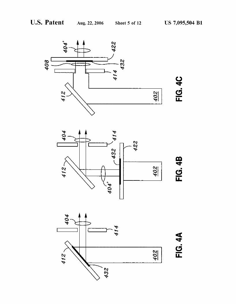
FIG. 4A shows mask placement as discussed in connec- Launcher”. tion with apodization mask 162. Here, an apodization mask FIG. 5 shows the beam paths in the illustrative interfer- 432 is formed on a reflective surface 412. When the incident ometer shown in FIG. 1. beam 402 is reflected, its intensity profile is suitable shaped. FIG. 6 is a screenshot taken from a solid-modeling FIG. 3B shows some examples of shaping. The shaped beam 35 program called IDEAS used to produce a solid-model ren- is then directed through an aperture 414, and if the intensity dering of the device and optical paths shown in FIG. 5. As profile is such that the beam is narrower than the aperture, noted above, the present invention has been embodied in a the exiting beam 404 will exhibit low diffraction artifacts. “racetrack” (RT) configured interferometer illustrated in
FIG. 4B shows a mask placement that is “upstream” in the FIG. 1 that operates in heterodyne mode and uses a “refer- incident beam; Le., the incident beam itself is shaped before 40 ence signal” against which the beat signal is compared to it falls on the optic element. Thus, a suitable transmissive determine changes in distance between the corner cube substrate 422 can be patterned with an appropriate apodiza- retro-reflector (“retros”) of the racetrack from their original tion mask 432. The apodization mask 432 in this case is separation distance. The “reference signal” is produced by therefore transmissive, rather than being reflective, so that taking a portion of the source beam that is used for mea- light can pass through and be shaped by the pattern formed 45 surement and mixing it with the local oscillator beam (LO on the substrate. Consequently, the apodized beam 404’ will beam). exhibit the desired intensity profile. When the apodized Referring to FIGS. 1 and 5, a first laser beam is provided beam 404’ is subsequently directed by the reflective surface to fiber optic 122a and is collimated by the collimator 102a 412 through the aperture 414, the exiting beam 404 will have to produce a source beam 502. The source beam 502 enters little or no diffraction artifacts. 50 the optic component 104 and is incident upon the double-
FIG. 4C shows a mask placement that is “downstream” in sided mirror 142. A second laser beam having a frequency an exit beam 408. Here, the incident beam 402 is directed different from the first laser beam is provide to fiber optic through the aperture 414 by reflective surface 412. Since the 122b and collimated by the collimator 102b to produce a width of the incident beam is greater than that of the aperture local oscillator beam (LO beam) 512. The LO beam also 414, the exit beam 408 will be subject to diffraction. The exit 55 enters the optic component 104 and is incident to the beam beam 408 is directed to an apodization mask 432 that is combining segment 144a of the mirror 144. The fold mirror patterned or otherwise formed on a substrate 422. The exit beam 408 is thereby shaped by the mask to produce an apodized beam 404’. Again, the substrate 422 is transmis- sive, with a suitable pattern to produce a transmissive 60 apodization mask.
It is noted that in FIGS. 4B and 4C, the substrate 422 itself can be machined (e.g., cutout) with an opening with a patterned edge. As mentioned above, the edge can be formed with a starburst pattern, or a tooth-gear pattern. Other 65 patterns can be used to obtain shaped beams having desired
112a may or may not be needed, depending on the physical location of the collimator 102b. The Risley prism pair 112c provides finely tuned alignment of that portion of the LO beam 512 that will be mixed with the reference beam.
The source beam 502 is directed to and reflected by the apodized surface (172, 162) to produce an apodized beam. According to the pattern shown in FIG. 3B for apodization mask 162, the apodized beam comprises a core beam portion which exits through the opening 182 with minimal or no diffraction distortions. This core beam portion constitutes a
intensity profiles. measurement beam 504 that propagates to a first retro (CC1
US 7,095,504 B1 9 10
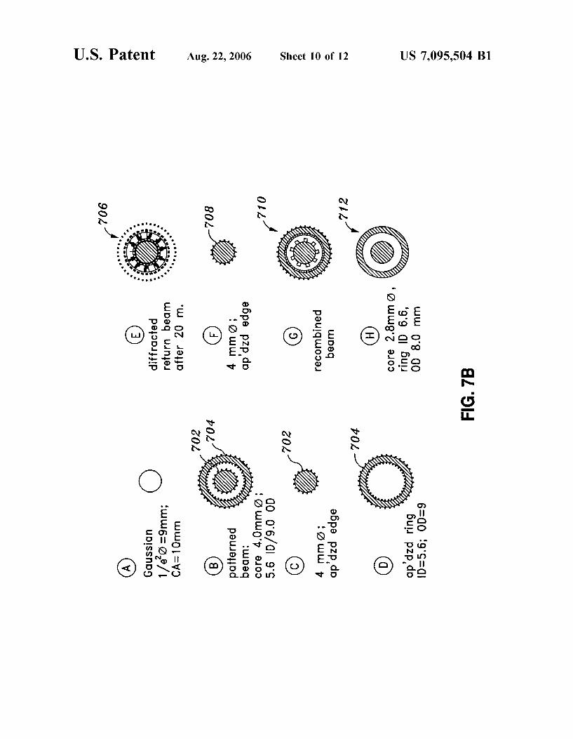
in FIG. 5A) and is reflected to a second retro CC2, returning the return beam, the return beam can be shaped and thus to the device as a return beam 506. The measurement beam cleaned up considerably to become the beam at location “F”. 504 in this interrogates the retros to be measured. The beam cross section 708 at location “F” represents the
The apodized beam also comprises a shadow region that apodized return beam. At location “G”, the reference beam falls on the edge between the reflective surface 176 and the 5 504’ is combined with the apodized return beam to produce opening 182. The apodized beam further comprises an concentric beam pattern 710 at “G”. The beams are com- annular beam portion that is incident upon the reflective bined with the LO beam 512 at the diffraction grating 177 surface 176 surrounding the opening 182. The annular beam (FIGS. 1 and 5) in order to create the heterodyne signal. The portion constitutes a reference beam 504’ that will be mixed resulting bundle of beams is cleaned up with a mask 108 to with a portion of the LO beam 512 to produce a “reference i o reduce signal cross-talk, resulting in beam pattern 712 at signal” used to compare against the beat signal. The refer- location “H’. ence beam 504’ is directed to a second reflective surface In order to highlight that an apodization mask can be 172a formed on the double-sided mirror 142. The second adapted in any interferometric device, FIG. SA shows an reflective surface 172a directs the reference beam toward the interferometer configuration based on a triple-axle-mirror diffraction grating 177. 15 design that is the subject of U.S. application Ser. No.
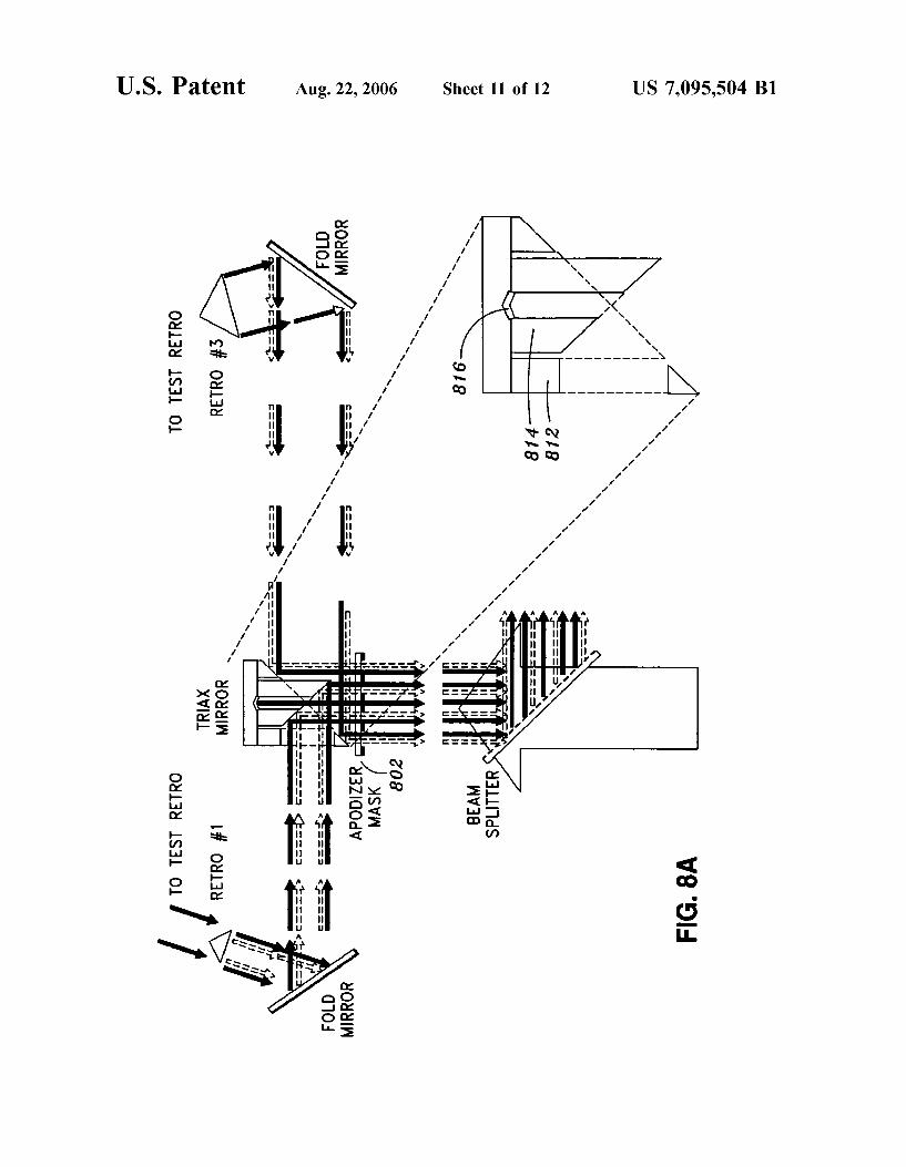
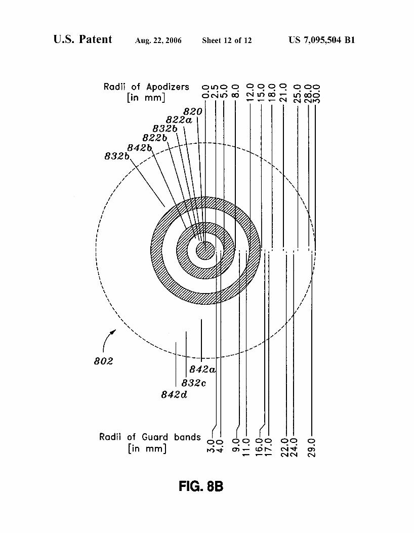
The return beam 506 enters the optic component 104 101180,086. The figure shows an improvement to the tri-ax through opening 183. The return beam 506 is apodized by mirror design disclosed in U.S. application Ser. No. 101180, the apodization mask 164 to produce an apodized return 086. The tri-ax mirror shown in FIG. SA comprises two beam 508. The apodized return beam 508 is then directed concentric annular mirrors, an outer annular mirror 812 and toward the diffraction grating 177 via the reflective surface 20 an inner annular mirror 814. The improvement includes the 174 and fold mirror 146. The reference beam and the a central mirror 816 about which the outer annular mirror apodized return beam 508 are recombined by the time the 812 and the inner annular mirror 814 are arranged. In the recombined beam is incident on the diffraction grating 177. embodiment shown in the figure, the central mirror 816 is a The diffraction grating mixes the LO beam 512 with the center cube retro-reflector. However, other mirror configu- recombined beam and are directed to a first photodetector of 25 rations are possible. The beam reflected by each annular the dual photodetector 106. The combining segment 144a is mirror comprises two concentric annular beams. FIG. SA configured as a beam splitter. Therefore, the mixed beams illustrates yet another embodiment of the present invention, (LO beam and recombined beam) propagate to the fold namely, a dual-sided apodization mask 802 disposed along mirror 1123, and are directed to a second photodetector of an optical path in the interferometer. the dual photodetector 106. FIG. 8B illustrates the pattern of the mask 802 shown in
Disposed in front of each of the two photodetectors is a FIG. SA. The pattern of the mask 802 has a central opening mask 108. This mask is provided to reduce signal cross-talk. 820 formed at the center of the mask 802, showing the Additional details of this mask are discussed in U.S. appli- central mirror 816 behind it. The pattern of mask 802 further cation Ser. No. 101293,209. comprises a number of concentric annular regions arranged
FIGS. 7A and 7B show cross-sectional views of the 35 about the central opening 820. Radial dimensions of the various beams shown in FIG. 5. A top view solid-model guard bands and the apodizers specific to an embodiment of rendering of the interferometer is shown in FIG. 7A. The the triax mirror (FIG. SA) are shown. various beams of interest are identified by reference letters There is an apodization region 822a to provide a transi- “A” through “H’. The cross-sectional views of the identified tion region from the central opening to a shadow region beams are shown in FIG. 7B. At location “A”, the collimated 40 (guard band) 832a. Referring to FIG. SA, an enlarged view source beam from the collimator 102a exhibits a standard of the triax mirror is provided to show that the dimensions Gaussian intensity cross section 702. At location “B”, the of the pattern of the mask 802 allow for the shadow region collimated source beam has been reflected off the patterned 832a to be aligned so as to envelope the inner edge of the mirror surface (162, 172) to become the patterned annular mirror 814 to reduce or eliminate diffraction arti- (apodized) beam seen at “B”. The cross section at “B’ shows 45 facts caused by edges. An apodization region 8223 provides a central core beam portion having an intensity cross section a transition from the shadow region 832a to a reflective 702. The central core beam portion constitutes the measure- region 842a. The reflective surface of the reflective region ment beam 504 in FIG. 5. The patterned beam at “B” also 842a faces into the page of the figure. This reflective surface shows an annular portion having an intensity cross section is aligned with one of the two annular beams incident to the 704. This annular portion constitutes the reference beam 50 inner annular mirror 814. Areflective region 8423 is aligned 504’ in FIG. 5. At location “C”, it can be seen that the with the other of the two annular beams incident to the inner intensity cross section 702 of the measurement beam 504, annular mirror 814 and, like the reflective region 842a, faces when it exits the optical component (beam launcher) 104, into the page. As can be seen in FIG. 8B, the reflective exhibits an apodized edge due to the beam shaping effect of surface 842a and 8423 are spaced apart by an apodization the apodization mask 162 (FIG. 1). The gear-teeth graphics 55 region, followed by a shadow region (guard band), followed in FIG. 7B are notational conventions used to represent an by an apodization region. apodized beam edges. The intensity cross section 704 of the A shadow region 8323 is formed between the reflective reference beam 504’ at location “D’ also shows apodized region 8423 and a reflective region 842c. The shadow region edges. 8323 blocks light from the space between the inner annular
The measurement beam 504 exits the optic component, 60 mirror 814 and the outer annular mirror 812. The reflective interrogates the two comer cube retro-reflector (retros) to be region 842c has its reflective surface facing out of the page. measured, and returns at location “E” as the return beam A shadow region 832c (and the corresponding apodization with an intensity cross section 706. The cross section 706 regions) separate the reflective region 842c from a reflective represents diffraction resulting from propagation of the region 842d. The reflective regions reflect the two annular measurement beam over a large distance and the reflection 65 beams which are incident on the outer annular mirror 812. of the measurement beam by the retros. However, by pro- FIG. 9 shows yet another apodization mask pattern, viding a suitable apodization mask 164 near the entrance for emphasizing that the pattern can be any suitable shape. Here,
30
US 7,095,504 B1 11
an apodization mask is formed with openings 902a and 902b. The apodization regions 912 in each opening are shown as gray regions. One technique for forming the apodization regions 912 is cutout “D’ shapes out of opaque material. The edges of the resulting “D’ shaped opening can be patterned with a zig-zag shaped edge 912a, or a gear- toothed edge 912b, or by some other similar pattern.
The above-described arrangements of apparatus and methods are merely illustrative of applications of the prin- ciples of this invention and many other embodiments and modifications may be made without departing from the spirit and scope of the invention as defined in the claims. The scope of the invention should, therefore, be determined not with reference to the above description, but instead should be determined with reference to the appended claims along with their full scope of equivalents.
What is claimed is: 1. An interferometry method of operation comprising
producing a reference beam of radiation; producing a measurement beam of radiation; directing said measurement beam of radiation to a target;
and receiving a reflected beam of radiation, said reflected
beam of radiation being a reflection of said measure- ment beam of radiation off of said target,
wherein at least one of said foregoing steps includes a step of apodizing a beam of radiation to produce a shaped beam.
2. The method of claim 1 wherein said shaped beam comprises a first beam portion, a second beam portion, and a shadow region that separates said first beam portion and said second beam portion, the method further comprising directing said shaped beam to an optical element that has an edge such that said edge lies within said shadow region.
3. The method of claim 1 wherein said shaped beam comprises a core beam portion, an annular beam portion that encircles said core beam portion, and an annular shadow region that separates said core beam portion and said annular beam portion, the method further comprising directing said shaped beam to a surface that that has an opening such that said core beam portion is transmitted through said opening, said annular shadow region envelopes an edge of said opening, and said annular beam portion is directed to an annular region of said surface that encircles said opening.
4. The method of claim 1 wherein said step of producing a measurement beam of radiation includes reflecting a source beam of radiation off of a reflecting surface to produce a first reflected beam of radiation.
5. The method of claim 4 wherein said reflecting surface includes an apodization mask formed thereon so that said first reflected beam of radiation is patterned by said apodiza- tion mask.
6. The method of claim 4 further comprises apodizing said source beam of radiation to shape said source beam of radiation prior to said step of reflecting said source beam of radiation.
7. The method of claim 4 further comprises apodizing said first reflected beam of radiation to shape said first reflected beam of radiation.
steps of:
8. The method of claim 1 further comprising: producing a local oscillator beam; mixing a portion of said local oscillator beam with said
reference beam of radiation to produce a reference signal; and
mixing a portion of said local oscillator beam with said reflected beam of radiation to produce a beat signal,
5
10
15
20
25
30
35
40
45
50
55
60
6 5
12 wherein interferometric measurements can be made by
comparing said reference signal with said beat signal, wherein said step of producing a reference beam of
radiation includes reflecting a source beam of radiation off of a reflecting surface to produce a first reflected beam of radiation.
9. The method of claim 8 wherein said reflecting surface includes an apodization mask formed thereon so that said first reflected beam of radiation is patterned by said apodiza- tion mask thereby producing a shaped beam.
10. The method of claim 9 wherein said shaped beam comprises a core beam portion, an annular shadow portion concentric with said core beam portion, and an annular beam portion concentric with said core beam portion, wherein said measurement beam of radiation comprises said core beam portion, wherein said reference beam of radiation comprises said annular beam portion.
11. The method of claim 8 further comprises apodizing said source beam of radiation to shape said source beam of radiation prior to said step of reflecting said source beam of radiation.
12. The method of claim 8 further comprises apodizing said first reflected beam of radiation to shape said first reflected beam of radiation.
13. The method of claim 8 wherein said source beam of radiation is one of infra-red (IR) light, visible light, and ultra-violet (w) light.
14. An interferometer comprising: means for generating one or more source beams; one or more first optic surfaces arranged to receive said
one or more source beams and to produce a reference beam and a measurement beam from said one or more source beams;
one or more second optic surfaces arranged to receive and to reflect a return beam, said measurement beam being directed to one or more targets and being reflected therefrom to produce said return beam;
a plurality of optical paths defined by said first optic surfaces and by said second optic surfaces;
a photodetector component disposed in line with one of said optical paths; and
at least one apodization mask disposed in line with one of said optical paths,
wherein a shaped beam can be produced from a beam incident upon said apodization mask.
15. The interferometer of claim 14 wherein said apodiza- tion mask comprises a pattern wherein said shaped beam comprises a first beam portion, a second beam portion, and a shadow region that separates said first beam portion and said second beam portion, wherein said shaped beam is directed to an optical element that has an edge and is incident upon said optical element such that said edge lies within said shadow region.
16. The interferometer of claim 14 wherein said shaped beam comprises a core beam portion, an annular beam portion that encircles said core beam portion, and an annular shadow region that separates said core beam portion and said annular beam portion, wherein said shaped beam is directed to a surface that that has an opening such that said core beam portion is transmitted through said opening, said annular shadow region envelopes an edge of said opening, and said annular beam portion is directed to an annular region of said surface that encircles said opening.
17. The interferometer of claim 14 wherein said first optic surfaces and said second optic surfaces are reflecting sur-
US 7,095,504 B1 13
faces, wherein said at least one apodization mask comprises an apodization pattern disposed on one of said reflecting surfaces.
18. The interferometer of claim 14 wherein said at least one apodization mask is disposed relative to an optic surface such that a beam incident upon said optic surface is shaped by said apodization mask before falling upon said optic surface.
19. The interferometer of claim 14 wherein said at least one apodization mask is disposed relative to an optic surface such that a beam leaving said optic surface is shaped by said apodization mask subsequent to leaving said optic surface.
20. The interferometer of claim 14 where said source beam is one of IR light, visible light, and W light.
21. An optical interferometer comprising: a source of a source beam; an optical component in alignment with respect to said
source to receive said source beam therefrom, said optical component configured to emit a measurement beam to a target, said measurement beam being obtained from said source beam; and
a detector in alignment with respect to said optical com- ponent, said optical component further configured to receive a return beam from said target, said optical component further configured to transmit one or more output beams to said detector whereby interferometric measurements can be performed, said one or more output beams being obtained from said return beam,
a first reflecting surface arranged to receive said source beam; and
an apodization mask disposed in proximity to said first reflecting surface to shape said source beam to produce a shaped source beam, wherein said mea- surement beam is obtained from said shaped source beam.
22. The optical interferometer of claim 21 wherein said optical component further comprises a second reflecting surface arranged in alignment with said return beam, and an additional apodization mask disposed in proximity to said second reflecting surface to shape said return beam to produce a shaped return beam.
23. The optical interferometer of claim 21 wherein said optical component further comprises a second reflecting surface having an opening formed therethrough and aligned with respect to said first reflecting surface so that said shaped source beam is transmitted to said second reflecting surface, wherein said shaped source beam comprises:
a core beam portion that can be transmitted through said opening with substantially no diffraction;
an annular shadow portion that envelopes the edge of said opening; and
an annular beam portion that is transmitted to an annular region of said second reflecting surface concentric with said opening.
24. The optical interferometer of claim 23 further com- prising a second source to produce a local oscillator beam, said optical component further being in alignment with said second source to receive said local oscillator beam, said optical component configured to mix said return beam with said local oscillator beam to produce a first output beam and to mix said annular beam portion with said local oscillator beam to produce a second output beam.
said optical component comprising:
5
10
15
20
25
30
35
40
45
50
55
60
14 25. The optical interferometer of claim 24 wherein said
apodization mask is deposited on said first reflecting surface. 26. The optical interferometer of claim 24 wherein said
apodization mask is formed on a transmissive substrate, said transmissive substrate being disposed along an optical path between said source and said first reflective surface.
27. The optical component of claim 24 wherein said source beam is one of W light, visible light, and IR light.
28. An interferometer comprising: one or more first optic surfaces arranged to receive one or
more source beams and to produce therefrom a plural- ity of beams, including a measurement beam;
one or more second optic surfaces arranged to receive and to reflect a return beam, said measurement beam being directed to one or more targets and being reflected therefrom to produce said return beam;
a plurality of optical paths defined by said first optic surfaces and by said second optic surfaces;
a photodetector component disposed in line with one of said optical paths; and
at least one apodization mask disposed in line with one of said optical paths,
wherein a shaped beam can be produced from a beam incident upon said apodization mask.
29. The interferometer of claim 28 wherein said apodiza- tion mask comprises a pattern wherein said shaped beam comprises a first beam portion, a second beam portion, and a shadow region that separates said first beam portion and said second beam portion, wherein said shaped beam is directed to an optical element that has an edge and is incident upon said optical element such that said edge lies within said shadow region.
30. The interferometer of claim 28 wherein said shaped beam comprises a core beam portion, an annular beam portion that encircles said core beam portion, and an annular shadow region that separates said core beam portion and said annular beam portion, wherein said shaped beam is directed to a surface that that has an opening such that said core beam portion is transmitted through said opening, said annular shadow region envelopes an edge of said opening, and said annular beam portion is directed to an annular region of said surface that encircles said opening.
31. The interferometer of claim 28 wherein said first optic surfaces and said second optic surfaces are reflecting sur- faces, wherein said at least one apodization mask comprises an apodization pattern disposed on one of said reflecting surfaces.
32. The interferometer of claim 28 wherein said at least one apodization mask is disposed relative to an optic surface such that a beam incident upon said optic surface is shaped by said apodization mask before falling upon said optic surface.
33. The interferometer of claim 28 wherein said at least one apodization mask is disposed relative to an optic surface such that a beam leaving said optic surface is shaped by said apodization mask subsequent to leaving said optic surface.
34. The interferometer of claim 28 where said source beam is one of IR light, visible light, and W light.
* * * * *


![(12) United States Patent US 8,346,887 B1 Kembel et a ... · (12) United States Patent Kembel et a]. US008346887B1 US 8,346,887 B1 *Jan. 1, 2013 (10) Patent N0.: (45) Date of Patent:](https://img.pdfslide.us/doc/110x75/5f51c9b29b67183a91659d37/12-united-states-patent-us-8346887-b1-kembel-et-a-12-united-states-patent.jpg)