Embed Size (px)
Citation preview
USOO8794072B2
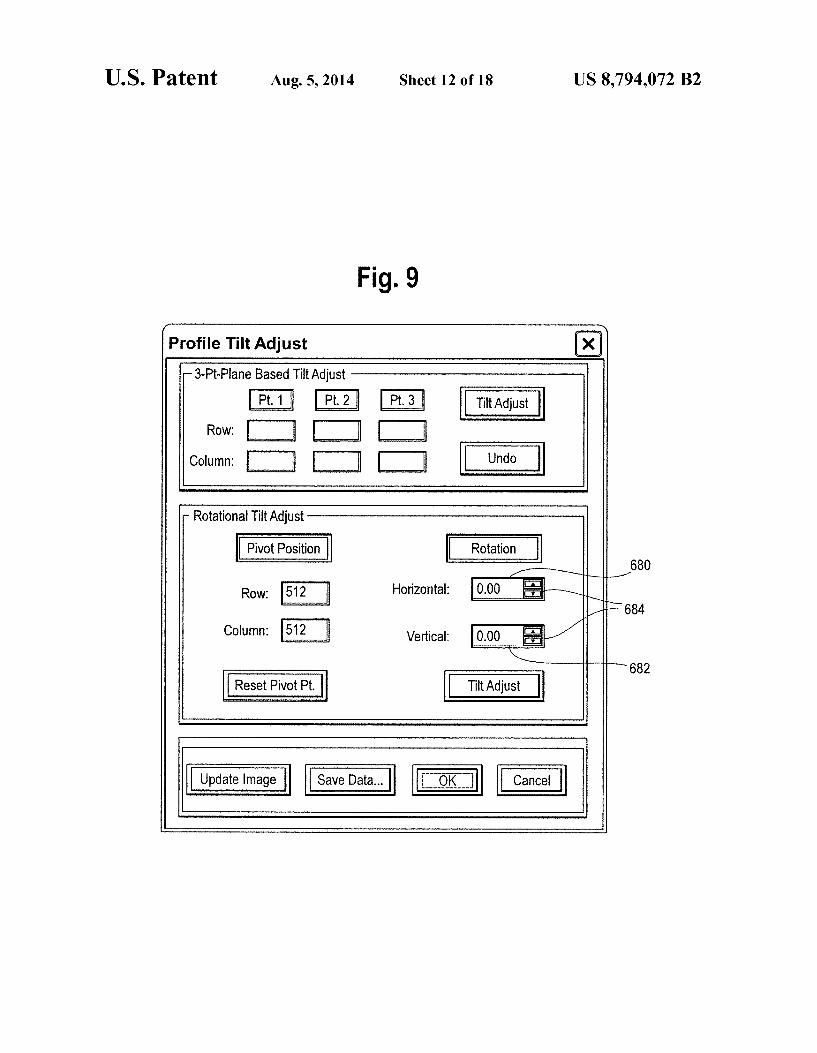
(12) United States Patent (10) Patent N0.: US 8,794,072 B2 Kessler et a1. (45) Date of Patent: Aug. 5, 2014
(54) SCANNING ACOUSTIC MICROSCOPE WITH 4,503,708 A * 3/1985 Kino et a1. .................... .. 73/628 PROFILOMETER FUNCTION 4,513,384 A * 4/1985 Rosencwaig .... .. 702/170
4,768,155 A * 8/1988 Takishita et al. 702/39 4,781,067 A * 11/1988 Cichanski . . . . . . . . . . . . . .. 73/620
(75) Inventors: Lawrence W. Kessler, Buffalo Grove, IL 5,029,476 A * 7/1991 Metala et al‘ N 73/620 (Us); Michael G- OraveCZ, Lombard, IL 5,241,287 A * 8/1993 Jen ................... .. .. 333/143 (US); Zhiqi Guo, Palatine, IL (US) 5,331,855 A * 7/1994 Takashita et a1. .. 73/602
5,475,613 A * 12/1995 Itoga et a1. . . . . . . . . . . . . .. 702/39
(73) Assignee: Sonoscan, Inc., Elk Grove Village, IL 5,602,336 A : 2/1997 TakeuChl et al' 73/624 Us) 5,641,706 A 6/1997 Tjaden et al. . . . . . . . . . .. 438/20
( 6,880,387 B2* 4/2005 Kessler et al. . . . . . . . . .. 73/105
_ _ _ _ _ 6,890,302 B2 * 5/2005 Oravecz et a1. .. 600/443
( * ) Notice: SubJeCI to any disclaimer, the term of this 6,981,417 B1 * 1/2006 OravecZ . . . . . . . . . . . . .. 73/619
patent is extended or adjusted under 35 7,132,617 B2* 11/2006 Lee et a1. ..... .. 219/109 U_S_C_ 154(b) by 697 day, 2003/0089171 A1* 5/2003 Kene?ck et a1. 73/597
2007/0180914 A1 * 8/2007 Kessler ......................... .. 73/607
(21) APP1-N0-I 12/2441460 OTHER PUBLICATIONS
(22) Filed: Oct, 2, 2008 DiStefano et 31., “Acoustic Contour Mapping”, IBM Technical Dis closure Bulletin, vol. 25, Issue 10, pp. 5103-5108, Mar. 1983*
(65) Prior Publication Data * cited by examiner
US 2009/0095086 A1 Apr. 16, 2009 Primary Examiner * Peter Macchiarolo
Related U-s- Application Data Assistant Examiner * Rose M Miller
(60) Provisional application No. 60/979,021, ?led on Oct. (74) Attorney) Agent) 0" Firm * MCCFaCken & Frank LLC 10, 2007, provisional application No. 61/038,460, ?led on Mar. 21, 2008. (57) ABSTRACT
A seaming acoustic microscope, includes an ultrasonic trans (51) Int- Cl- ducer, a data storage memory, a display, a scanner assembly,
G01N29/06 (2006-01) and a controller. The controller is adapted to cause the motor (52) U-s- CI- to move the transducer along a path With respect to a sample,
USPC ............................................. .. 73/634; 73/633 and cause the ultrasonic transducer to emit a pulse of acoustic
(58) Field of Classi?cation Search energy towards the sample at each point in a plurality of USPC .................................................. .. 73/ 633, 634 points along the path. In addition, the controller is adapted to See application ?le for complete search history. cause the ultrasonic transducer to receive a set of re?ection
signals that correspond to each of the pulses emitted there (56) References Cited from. The sets of re?ection signals are used to generate an
US. PATENT DOCUMENTS image of a pro?le of the sample and an image representative of acoustic impedance features in the interior of the sample. The image of the pro?le of the sample shows a variation in
DEPTH
GATE SELECTION
DETECTOR
SIGNAL SIGNAL 1 N
SIGMA AMPLITUDE PEAK
DETECTION DATA
238 1
AMPLITUDE PEAK
DETECTION ACQUISITION ALGORITHM
2,937,522 A * 5/1960 McGaughey ................. .. 73/633 _ 3,792,613 A * 2/1974 Couture ,,,,,,,, u 73/629 height across a surface ofthe sample. 4,021,771 A * 5/1977 Collins et a1. .... .. 367/8
4,455,872 A * 6/1984 Kossoffet a1. ................ .. 73/618 22 Claims, 18 Drawing Sheets
11 PHI
v ’ comib?m ‘—
TRIGGER——_I r 210 V f— 2“ comm" WAVEFORM
ZAXIS 108‘ l l ACQUISITIOFN d ACTUATOR “'“I‘ " 226
PULSERI r 218 RECEIVER PROFILE
ECHO TIME WAVEFORM m, —I DETECTION M X l V AXIS 224 ALGORITHM
ACTUATOR SIGN“ WAVEFDRMa momma DISPLAY
INTERNAL IMAGE N DATA
INTERNAL IMAGE 1 DATA
142 ’— COMPUTER NETWORK OR OTHER STORAGE
US 8,794,072 B2 Sheet 1 0f 18 Aug. 5, 2014 US. Patent
all:
MMAJOthOU ZOFOE .ilv. gamma Ewwwwx > .wgm
Q.
wwmuOmm +
.501 5k »
Emma 4“ £3
‘15
mUQw
v .QE
8wilW:

US. Patent Aug. 5, 2014 Sheet 3 0f 18 US 8,794,072 B2
308
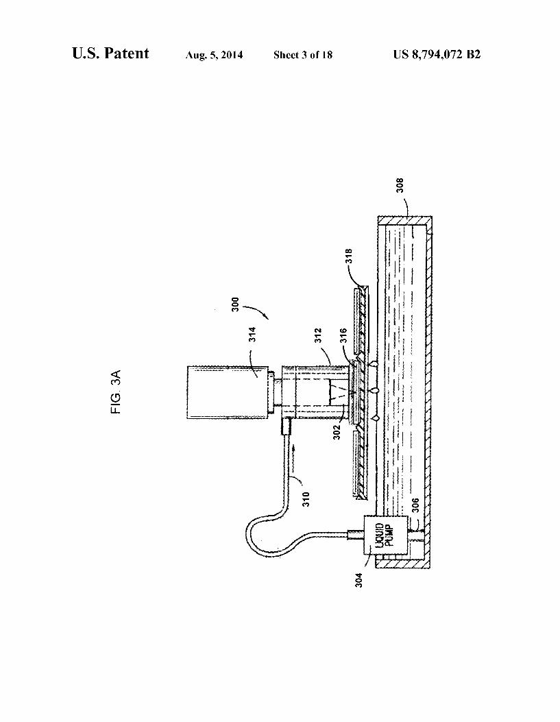
FIG. 3A

US. Patent Aug. 5, 2014 Sheet 4 0f 18 US 8,794,072 B2
352

US. Patent Au .5 2014 Sheet6 0f 18

US. Patent Aug. 5, 2014 Sheet 7 0f 18 US 8,794,072 B2
FlG. 5A
US. Patent Aug. 5, 2014 Sheet 8 0f 18 US 8,794,072 B2
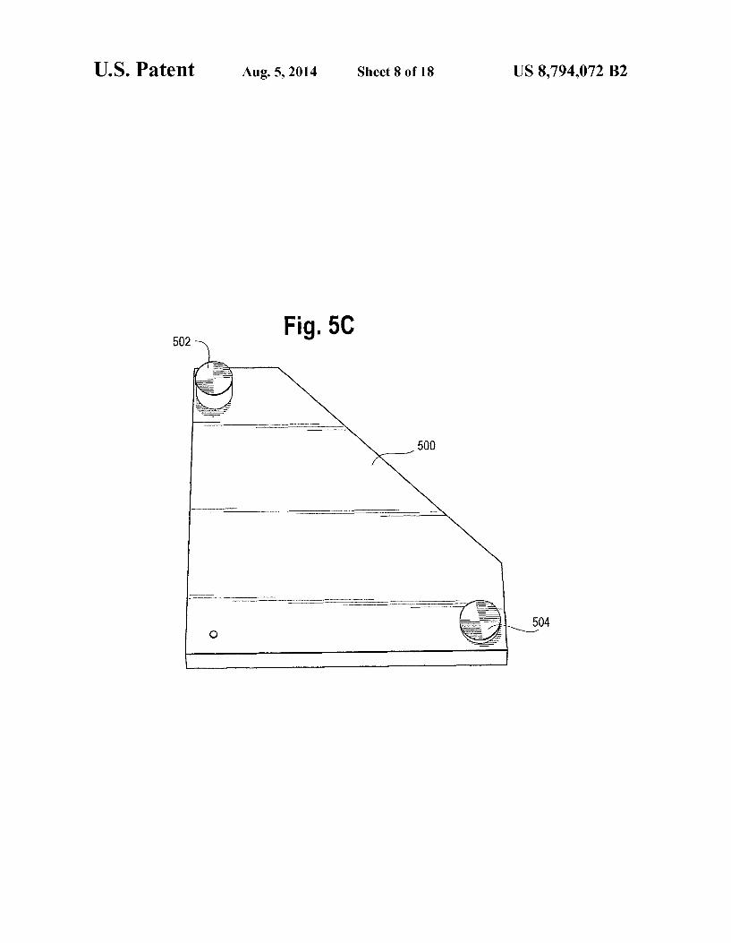
Fig. 50 502
504

US 8,794,072 B2 Sheet 9 0f 18 Aug. 5, 2014 US. Patent
02
www K

US. Patent Aug. 5, 2014 Sheet 10 0f 18 US 8,794,072 B2
FlG. 7
r 650 f 652
CONTROLLER <-—--—-—--> ROLL MOTOR
654 656 F F
PITCH MOTOR -—---———-————> TILT FIXTURE
US. Patent Au .5 2014 Sheet 11 0f 18
US. Patent Aug. 5, 2014 Sheet 12 0f 18 US 8,794,072 B2
Flg. 9 r’ ’ \
Profile Tilt Adjust
- 3-Pt-PIane Based Tilt Adjust
I PM I | P12 II I Pt-3 II TiItAdjust
Row: I II I II I II Column: I II I II I II Und"
— Rotational Tilt Adjust
Pivot Position 1 Rotation ‘ 680
t \_r,,/
ROW; 512 Horizontal: .000 _\ /1>684
comm": 512 Vertical: 10.00
I 682
I Reset Pivot Pt. ‘ Tilt Adjust
Update Image Save Data... {:Ip'Kj CanceI

US. Patent Aug. 5, 2014 Sheet 13 0f 18 US 8,794,072 B2
FIG. 10A FIG. 1GB

US. Patent Aug. 5, 2014 Sheet 14 0f 18 US 8,794,072 B2
Fig. 11
EgDia-Sllcoimage .. I: x
?fe Wm Enhance BO! Hall's-s SpedaMcldes ?ab
Angsiuand?ounl. . , _ Own amt-is: am
Rum ROI SENPM‘S) 9 Mrslzamdgum m Showhuvl?nduw Data 0 I
D snowkuQummDsm
[:I Show Ccmor Vul'd: E Show LagestVoid
[3 Shaw Siza Data @ Pixals
0 Sq- um ] 0 Sq. mm D Sq.in. Medwn Lama § Defect Rages: at urAbovu E [:1 E
E E Show Gaunt Window Data U Show Count Quadrant Data
B Show Curvature Dana 9 mm” '050
C] Sum??n E“
'I']\ Input A Filter: AEnhancu w Output / J ZoomFach?O [ a, 100? @2033, 209 [111, 255 [1

US. Patent Aug. 5, 2014 Sheet 15 0f 18 US 8,794,072 B2
FIG. 12 F m
START SCAN 702
‘ NEXT PIXEL
POSlTION ( 704 PIXEL TRIGGER
706 708
f— V V PULSER JREATES A WAVEFORM ACOUSTIC PULSE ACQUISITION BEGINS 710
+ SURFACE REFLECTION
ECHO RECEIVED * /'\712
WAVEFORM ACQUISITION ENDS
r /\ 714 SURFACE ECHO TOF
DETERMINED ‘ 716
SURFACE ECHO TIME STORED
718 _________--_-__-_I V
IMAGE DATA DISPLAYED
AVE ALL PIXELS BEE ‘
f 722 ACQUIRED?
END RASTER SCAN
SURFACE CURVATU '
ENABLED?
CALCULATE SURFACE CURVATURE
720
SURFACE CURVATU ‘
CEPTIREJECT ENABLE I
GET INPUT OF BOUNDS
SURFACE CURVATU '
OUTSIDE BOUNDS?
728
732 r 734 REJECT END
ACCEPT END

US. Patent IAug.5,2014 Sheetl60f18
FIG. 12A
738
AMPLITUDE PEAK ACQUISITION BEGINS
REFLECTION AND/OR
i r' 740 TRANSMISSION ECHO RECEIVED
I 742
PEAK SIGNAL ACQUIRED
I f - 744
PEAK SIGNAL STORED " 746
AMF’LITUDE PEAK ACQUISITION ENDS
US 8,794,072 B2

US. Patent Aug. 5, 2014 Sheet 17 0f 18 US 8,794,072 B2
l HI lamina
nil!
Miiiiiilllllllllu

US. Patent Aug. 5,2014 Sheet 18 0f 18 US 8,794,072 B2
FIG. 14 r 800
GATHER PROFILE AND INTERNAL DATA
REQUENCY DOMAI REPRESENTATION?
GET USER SELECTED DATA
‘P 806
v /
FOURIER TRANSFORM WITH USER DATA
v f’“ 808
DISPLAY FREQUENCY DOMAIN SIGNAL
810
TIME DOMAIN REPRESENTATION?
f 812
DISPLAY TIME DOMAIN SIGNAL
DISPLAY PROFILE?
GENERATE PROFILE AND DISPLAY
END
US 8,794,072 B2 1
SCANNING ACOUSTIC MICROSCOPE WITH PROFILOMETER FUNCTION
CROSS-REFERENCE TO RELATED APPLICATION
The content of US. provisional application Ser. No. 60/979,021, ?led Oct. 10, 2007 and 61/038,460, ?led Mar. 21, 2008 is incorporated by reference into this application as if fully set forth herein. The following US patents and applica tions are assigned to Sonoscan, and generally relate to various aspects of scanning acoustic microscopy: US. Pat. Nos. 4,518,992, 4,781,067, 4,866,986, 5,351,544, 5,684,252, 6,357,136, 6,460,414, 6,880,387, 6,890,302, 6,895,820, 6,981,417, and 7,000,475, as well as Ser. No. 11/626,177 ?led Jan. 23, 2007. All such patents and applications are incorpo rated by reference as if fully set forth herein.
DESCRIPTION OF RELATED ART
As is well known in the art a scanning acoustic microscope typically comprises a transducer which is driven by voltage pulses which may have amplitudes of, for example, 100 volts or more and are typically in the frequency range of tens of megahertz to 100 megahertz or higher.
The pulsed acoustic beam penetrates the target, which may be an IC package, for example. A fraction of the energy passes through the target, and the remainder is absorbed, scattered, or re?ected. In many applications su?icient energy is returned to the transducer (after a delay) to be sensed. Acoustic energy is almost totally re?ected by an air gap. Thus acoustic micro scopes have proven to be extremely useful in locating dis bonds (air gaps) between internal layers of a device such as an IC package.
The return signal is an echo composed of a range of fre quencies centered around the transducer’ s resonant fre quency. As described further in US. Pat. No. 6,981 ,417, the return signal is commonly known as the “A” waveform or “A-scan”, and in practice contains a great deal of information about acoustic impedance perturbations or features in the body of the IC package. As is well known in the art, a time domain signal received
by the acoustic microscope during a scanning session is con ventionally gated by a gating process. During the gating pro cess, a gate isolates a pixel-representative signal segment associated with a single pixel.
Gating of the signal permits a user to examine any chosen level in the target simply by selecting an appropriate delay time for the gate. For example, a single pixel segment might be captured with a gate 100 nanoseconds wide set at a delay of 384-484 nanoseconds. If a deeper level were to be visual ized, a longer delay would be employed.
SUMMARY OF THE DISCLOSURE
In accordance with the invention, there is provided a scan ning acoustic microscope capable of collecting and display ing any pro?le image of a sample including a surface pro?le, an internal pro?le or any combination of the two.
In accordance with another aspect of the invention, the scanning acoustic microscope may also be capable of simul taneously collecting and displaying an internal acoustic image of a sample.
In accordance with yet another aspect of the invention, the scanning acoustic microscope may be con?gured to simulta neously display a surface pro?le, a time domain signal rep
20
25
30
35
40
45
50
55
60
65
2 resentation, a frequency domain signal representation, or any representation of features on or within a sample.
BRIEF DESCRIPTION OF THE DRAWINGS
FIG. 1 is a schematic illustration of an acoustic imaging microscope.
FIG. 2 is a schematic illustration of an alternative acoustic imaging microscope.
FIGS. 3A and 3B illustrates alternative transducer assem blies which may be implemented in certain applications of the present invention.
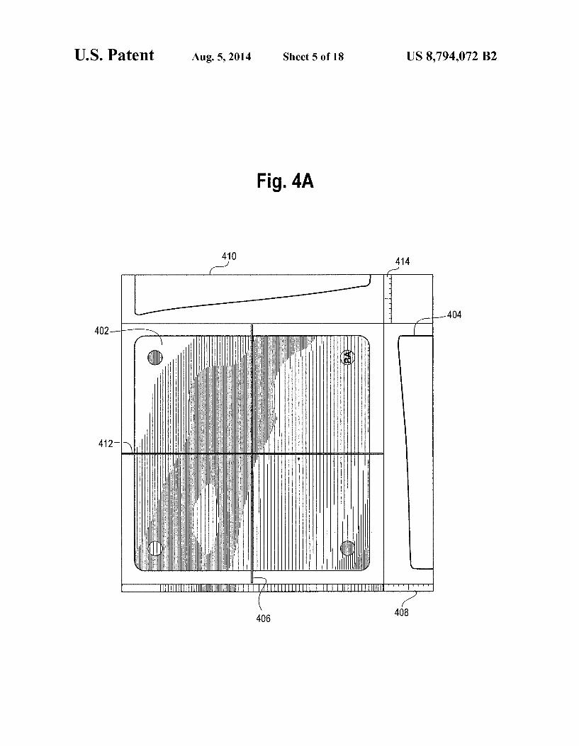
FIG. 4A is an illustration of a pro?le scan of an integrated chip useful in understanding an aspect of the present inven tion.
FIG. 4B is a 3-dimensional illustration of an integrated chip.
FIG. 5A illustrates a side view of an ultrasonic pulse that is directed towards a tilted part.
FIG. 5B is a schematic diagram showing how an exemplary tilt ?xture can be rotated about two different axes.
FIG. 5C is an annotated perspective view of an exemplary tilt ?xture shown with exemplary roll and pitch axes.
FIG. 6 is a ?owchart showing the steps of manually adjust ing a tilt ?xture.
FIG. 7 is a schematic block diagram of a system that allows a scanning acoustic microscope to perform tilt adjustment measurements under automatic control.
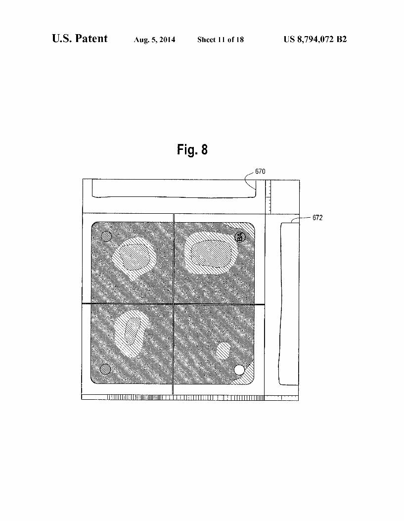
FIG. 8 is a normalized pro?le scan of the IC illustrated in FIG. 4A.
FIG. 9 is an illustration of a pro?le tilt adjust screen used to manually normalize a pro?le image.
FIGS. 10A and 10B is an illustration of excessive warpage of a part.
FIG. 11 illustrates a graphical user interface allowing a user to specify warpage information.
FIG. 12 is a ?owchart that shows program steps that are followed to allow a scanning acoustic microscope to collect acoustic pro?le information.
FIG. 12A is a ?ow chart used in conjunction with FIG. 12 to allow a scanning acoustic microscope to simultaneously collect internal and pro?le acoustic information.
FIG. 13A-13C is an illustration of a pro?le image, time domain image, and frequency domain image capable of being displayed simultaneously.
FIG. 14 is a ?ow chart illustrating how a user can cause visual indication of surface pro?le data to be simultaneously displayed with a time domain signal representation and/or a frequency domain signal representation.
DETAILED DESCRIPTION
FIG. 1 illustrates in highly schematic form an acoustic imaging microscope, shown as being adapted to inspect a sample, for example, an integrated circuit (“IC”) package 94 submerged in a coupling medium 96. Although an IC is used in the example, the sample may be any of a variety of tangible objects and is not restricted to an IC. A sample may be, for example, a ceramic plate, a diamond, a medical device, a machine plate, or an electrical component such as a capacitor or a transistor. A pulser 98, under the control of a motion controller 100 excites a transducer 102 to generate a pulsed ultrasonic probe 104, typically at frequencies ranging from 10 MHz or lower to 230 MHz or higher. The transducer 102 is scanned in X, Y, and Z coordinates by an X-Y-Z stage 106 through an X-Y-Z stage driver 108 under the control of motion controller 100.


![(12) Ulllted States Patent (10) Patent N0.: US 7,705,177 ... · US007705177B2 (12) Ulllted States Patent (10) Patent N0.: US 7,705,177 B2 Oniciu et a]. (45) Date of Patent: Apr. 27,](https://img.pdfslide.us/doc/110x75/60b0c9a58b545159f300a441/12-ulllted-states-patent-10-patent-n0-us-7705177-us007705177b2-12.jpg)
![(12) (10) Patent N0.: US 7,198,213 B2 United States Patent · 2017. 1. 19. · United States Patent US007198213B2 (12) (10) Patent N0.: US 7,198,213 B2 Kolbet et a]. (45) Date of](https://img.pdfslide.us/doc/110x75/60bfc79629246005d7520b44/12-10-patent-n0-us-7198213-b2-united-states-patent-2017-1-19-united.jpg)
![(12) United States Patent (10) Patent N0.: US 8,966,642 B2 ... · Quinn et a]. (45) Date of Patent: Feb. 24, 2015 ... Patent Feb. 24, 2015 Sheet 2 0f6 US 8,966,642 B2 202 \ ( TRUST](https://img.pdfslide.us/doc/110x75/5fdf168eff81f25e1d01d257/12-united-states-patent-10-patent-n0-us-8966642-b2-quinn-et-a-45.jpg)