Embed Size (px)
Citation preview
94
88
98
IMAGINGSIGNALS ^► , ,
72
f— HIFU IN
TRANSDUCER
U FOCUSHIFU
ULTRASOUNDIMAGINGPROBE
E_ 72
(12) United States PatentOwen et al.
(54) METHOD AND SYSTEM TO SYNCHRONIZEACOUSTIC THERAPY WITH ULTRASOUNDIMAGING
(75) Inventors: Neil Owen, Seattle, WA (US); MichaelR. Bailey, Seattle, WA (US); JamesHossack, Duvall, WA (US)
(73) Assignee: University of Washington, Seattle, WA(US)
(*) Notice: Subject to any disclaimer, the term of thispatent is extended or adjusted under 35U.S.C. 154(b) by 531 days.
(21) Appl. No.: 11/206,640
(22) Filed: Aug.17, 2005
(65) Prior Publication Data
US 2007/0055155 Al Mar. 8, 2007
(51) Int. Cl.
A61B 17122 (2006.01)(52) U.S. Cl . ............................... 600/459; 601/3; 601/2;
601/4; 310/311; 310/322; 310/334; 600/439(58) Field of Classification Search ................. 600/439,
600/443, 437, 459; 601/2, 3, 4; 607/72;29/59; 310/311, 322, 334
See application file for complete search history.
(56) References Cited
U.S. PATENT DOCUMENTS
125,623 A * 4/1872 Kelly et al . ................... 70/170
RE33,590 E 5/1991 Dory ..................... 128/660.03
5,039,774 A 8/1991 Shikinami et al .............. 528/60
5,065,742 A 11/1991 Belikan et al . ................ 128/24
5,080,101 A 1/1992 Dory ..................... 128/660.03
5,080,102 A 1/1992 Dory ..................... 128/660.03
5,150,712 A 9/1992 Dory ..................... 128/660.03
RR
^J INAGING- 96SIGNALS
94
"IFUFOCUS SCATTERED
98 ^ SIGNAL
(lo) Patent No.: US 7,621,873 B2(45) Date of Patent: Nov. 24, 2009
5,219,401 A 6/1993 Cathignol et al. ...... 128/660.03
5,311,869 A 5/1994 Okazaki................ 128/660.03
5,391,140 A 2/1995 Schaetzle et al ................ 601A
5,394,877 A 3/1995 Orr et al . .................... 600/459
(Continued)
FOREIGN PATENT DOCUMENTS
DE 04230415 Al 3/1994
(Continued)
OTHER PUBLICATIONS
Vaezy, Shahram et al. 2001. "Acoustic surgery." Physics World(August): 35-39.
(Continued)
Primary Examiner Long V LeAssistant Examiner Joel F Brutus(74) Attorney, Agent, or Firm Ronald M. Anderson
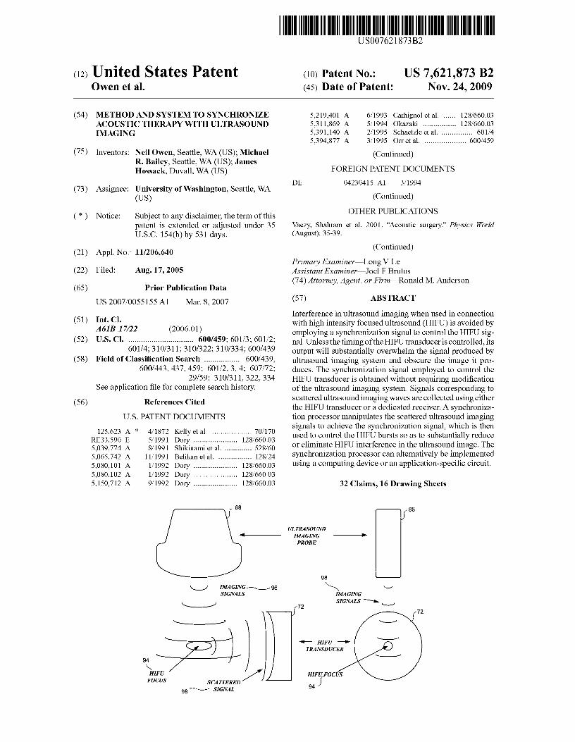
(57) ABSTRACT
Interference in ultrasound imaging when used in connectionwith high intensity focused ultrasound (HIFU) is avoided byemploying a synchronization signal to control the HIFU sig-nal. Unless the timing of the HIFU transducer is controlled, itsoutput will substantially overwhelm the signal produced byultrasound imaging system and obscure the image it pro-duces. The synchronization signal employed to control theHIFU transducer is obtained without requiring modificationof the ultrasound imaging system. Signals corresponding toscattered ultrasound imaging waves are collected using eitherthe HIFU transducer or a dedicated receiver. A synchroniza-tion processor manipulates the scattered ultrasound imagingsignals to achieve the synchronization signal, which is thenused to control the HIFU bursts so as to substantially reduceor eliminate HIFU interference in the ultrasound image. Thesynchronization processor can alternatively be implementedusing a computing device or an application-specific circuit.
32 Claims, 16 Drawing Sheets
US 7,621,873 B2Page 2
U.S. PATENT DOCUMENTS
5,471,988 A 12/1995 Fujio et al .............. 128/660.035,474,071 A 12/1995 Chapelon et al ............. 600/4395,492,126 A 2/1996 Hennigeetal . ............. 600/4395,507,790 A 4/1996 Weiss ......................... 607/1005,522,878 A 6/1996 Montecalvo et al. ........ 607/1525,526,815 A 6/1996 Granz et al. ........... 128/660.035,558,092 A 9/1996 Unger et al. ........... 128/660.035,573,497 A 11/1996 Chapelon ....................... 601/25,666,954 A 9/1997 Chapelon et al ............. 600/4395,720,286 A 2/1998 Chapelon et al ............. 600/4395,720,287 A 2/1998 Chapelon et al ............. 600/4395,769,790 A 6/1998 Watkins et al ............... 600/4395,817,021 A 10/1998 Reichenberger ............. 600/4395,823,962 A 10/1998 Schaetzle et al ............. 600/4395,827,204 A 10/1998 Grandia et al .................. 601/25,833,647 A 11/1998 Edwards ...................... 604/225,873,828 A 2/1999 Fujio et al ................... 600/4395,895,356 A 4/1999 Andrus et al ................ 600/4395,993,389 A 11/1999 Driscoll, Jr. et al.......... 600/3716,007,499 A 12/1999 Martin et al . .................. 601/36,039,694 A 3/2000 Larson et al . ............... 600/4596,050,943 A 4/2000 Slayton et al . .............. 600/4396,179,831 B1 1/2001 Bliweis ....................... 606/216,221,015 B1 4/2001 Yock .......................... 600/4396,409,720 B1 6/2002 Hissong et al . ............... 606/276,425,867 B1 7/2002 Vaezy ........................ 600/4396,491,672 B2 12/2002 Slepian et al . .............. 604/2676,595,934 B1 7/2003 Hissong et al . ................ 601/36,599,256 B1 7/2003 Acker et al . ................... 601/26,626,855 B1 * 9/2003 Weng et al . .................... 601/36,633,658 B1 10/2003 Dabney et al . .............. 382/1286,656,136 B1 12/2003 Weng et al . .................... 601/26,676,601 B1 * 1/2004 Lacoste et al . .............. 600/4396,685,639 B1 2/2004 Wang et al . ................. 600/4396,716,184 B2 * 4/2004 Vaezy et al . ................... 601/36,719,699 B2 4/2004 Smith ......................... 600/4596,726,627 B1 * 4/2004 Lizzi et al . .................. 600/4396,846,291 B2 1/2005 Smith et al .................. 600/459
2002/0193681 Al 12/2002 Vitek et al . ................. 600A I I2003/0069569 Al 4/2003 Burdette et al . ............... 606/272003/0125623 Al 7/2003 Kelly et al . ................. 600/4372004/0019278 Al 1/2004 Abend ........................ 600/5452004/0030268 Al* 2/2004 Weng et al . .................... 601/22004/0078034 Al 4/2004 Acker et al . .................. 606/272004/0097805 Al 5/2004 Verard et al ................. 600/4282004/0097840 Al 5/2004 Holmer ......................... 601/22004/0122493 Al* 6/2004 Ishibashi et al . .............. 607/962004/0143186 Al 7/2004 Anisimov et al. ........... 600/4372004/0153126 Al 8/2004 Okai ............................. 607/12004/0181178 Al 9/2004 Aldrich et al . ................. 601/32004/0234453 Al 11/2004 Smith ......................... 424/9.5
FOREIGN PATENT DOCUMENTS
EP 01265223 B1 11/2002WO WO 00/72919 12/2000
OTHER PUBLICATIONS
Vaezy, Shahram et al. 2001. "Experimental Investigations and DeviceDevelopment." First International Workshop on the Application ofHIFU in Medicine. (May 1-13): 4pp.Ostensen, Jonny, PhD; Bendiksen, Ragner, MSc. "Characterizationand Use of Ultrasound Contrast Agents." Acad Radiol 2002; 9(suppl2):S276-S278.Klibanov, Alexander L.; Rasche, Peter T.; Hughes, Michael S.;Wojdyla, Jolette K.; Galen, Karen P.; Wiblee, James H.;Brandenburger, Gary H. "Detection of Individual Microbubbles of anUltrasound contrast Agent: Fundamental and Pulse Inversion Imag-ing'." Acad Radiol 2002, 9(suppl 2):S279-S281.
Bauer, A.; Solbiati, L.; Weissman, N. "Ultrasound Imaging withSonoVue: Low Mechanical Index Real-time Imaging." Acad Radiol2002, 9(suppl 2):S282-S284.Watkin, Kenneth L., PhD; McDonald, Michael A., BS. "Multi-ModalContrast Agents: A First Step'." Acad Radiol 2002, 9(suppl 2): S285-S287.Watkin, Kenneth L., PhD; McDonald, Michael A., BS. "Schematic ofthe Tube, Cross Section Ultrasound Images of the Tube With Differ-ent Contrast Media (CM)." Acad Radiol2002,9(suppl 2):S288-S289.Wickline, Samuel A., MD; Hughes, Michael, PhD; Ngo, Francis C.,MD; Hall, Christopher, S., PhD; Marsh, Jon, N., PhD; Brown, PeggyA; Allen, John S., BS; McLean, Mark D.; Scott, Michael J., BS;Fuhrhop, Ralph W.; Lanza, Gregory M., MD, PhD. "Blood ContrastEnhancement with a Novel, Non-Gaseous Nanoparticle ContrastAgent'," Acad Radiol 2002, 9(suppl 2): S290-S293.Indman, Paul, MD, "Alternatives in Gynecology" Hysteroscopy2000 OBGYN.net <http://www.gynaltematives.com/hsc.html >.Kaczkowski, Peter J.; Vaezy, Shahram; Martin, Roy; Crum,Lawrence. "Development of a High Intensity Focused UltrasoundSystem for Image-Guided Ultrasonic Surgery." Ultrasound for Sur-gery 2001. <http://cimu.apl.washingion.edu/hifusurgerysystem .html>.Physicians. "Breast Cancer Insightec: focused ultrasound for noninvasive treatment." FAQ <http://www.exablate2000.com/physiciansfaq.html>.Owaki, T., Nakano, S. Arimura, K., Aikou, T. "The Ultrasonic Coagu-lating and Cutting System Injuries Nerve Function." First Depart-ment of Surgery, Kagoshima University School of Medicine,Kagoshima, Japan, Endoscopy. (2002): 575-579.Rivens, I.H., Rowland, I.J., Denbow, M., Fisk, N.M., Harr, G.R.,Leach, M.O. "Vascular Occlusion Using Focused Ultrasound Sur-gery for Use in Fetal Medicine." European Journal of Ultrasound 9(1999): pp. 89-97.Tachibana, Katsuro and Shunro MD, PhD. "The Use of Ultrasoundfor Drug Delivery." First Department of Anatomy, Fukuoka Univer-sity School of Medicine, Nanakuma, Japan,Echocardiography.(2001): 323-328.Ka-yun Ng, Yang Liu. "Therapeutic Ultrasound: Its Application inDrug Delivery." Medicinal Research Reviews, vol. 22, 204-223,2002.Porter, T.R., Xie, F. "Ultrasound, Microbubbles and Thrombolysis."Progress in Cardiovascular Diseases, vol. 44, No. 2, Oct. 2001: 101-110.Nobuki Kudo, Takehiro Miyaoka, Kengo Okada, and KatsuyukiYamamoto. "Study on Mechanism of Cell Damage Cased byMicrobubbles Exposed to Ultrasound." Graduate School of Engi-neering, Hokkaido University, Japan, Research Institute for Elec-tronic Science, Hokkaido University, 060-0812 Japan.Holt, Glynn R., Roy, Ronald A., Edson, Patrick A., Yang, Xinmai."Bubbles and Hifu: the Good, the Bad and the Ugly." Boston Uni-versity, Department ofAerospace and Mechanical Engineering, Bos-ton, MA 02215: 120-131.Everbach, Carr E. and Charles W. Francis. "Cavitational Mechanismsin Ultrasound-Accelerated Thrombolysis at 1 MHz." Ultrasound inMed. & Biol., vol. 26, No. 7, pp. 1153-1160, 2000.Brayman, Andrew A., Lizotte, Lynn M., Miller, Morton W. "Erosionof Artificial Endothelia In Vitro by Pulsed Ultrasound: AcousticPressure, Frequency, Membrane Orientation and Microbubble Con-trast Agent Dependence." Ultrasound in Med. & Biol., vol. 25, No. 8,pp. 1305-1320, 1999. Copyright 1999 World Federation forUltrasound in Medicine & Biology.Poliachik, Sandra L., et al. "Effect of High-Intensity FocusedUltrasound on Whole Blood With or Without Microbubble ContrastAgent." Ultrasound in Med. & Biol., vol. 25, No. 6, 1999: 991-998.Poliachik, Sandra L., et al. "Activation, Aggregation and Adhesion ofPlatelets Exposed to High-Intensity Focused Ultrasound."Ultrasound in Med. & Biol., vol. 27, No. 11, pp. 1567-1576, 2001.Rosenschein, Uri, et al. "Ultrasound Imaging-Guided NonivasiveUltrasound Thrombolysis-Preclinical Results." © 2000 AmericanHeart Association, Inc. (Circulation. 2000;102:238-245.) <http://www.circulationaha.com.org >.
US 7,621,873 B2Page 3
Tachibana, Katsuro, and Shunro MD, PhD. "Albumin MicrobubbleEcho-Contrast Material as an Enhancer for Ultrasound AcceleratedThrombolysis." (Circulation, 1995;92: 1148-1150.) © 1995 Ameri-can Heart Association, Inc.
Miller, Morton W. et al. "A Review of In Vitro Bioeffects of InertialUltrasonic Cavitation From a Mechanistic Perspective." Ultrasoundin Med. & Biol., vol. 22, No. 9, pp. 1131-1154, 1996.
Rosenschein, Uri, et al. "Shock-Wave Thrombus Ablation, A NewMethod for Noninvasive Mechanical Thrombolysis." The AmericanJournal of Cardiology, vol. 70, Issue 15, Nov. 1992: pp. 1358-1361.
Guzman, Hector R. et al. "Ultrasound-mediated disruption of cellmembranes. IL Heterogeneous effects on cells." J. Acoust. Soc. Am110 (1), Jul. 2001: pp. 597-606.Guzman, Hector R. et al. "Ultrasound-Mediated Disruption of CellMembranes. L Quantification of Molecular uptake and Cell Viabil-ity" J. Acoust Soc. Am. 110 (1), Jul. 2001: pp. 588-595.Hynynen, Kullervo et al. "Potential Adverse Effects of High-Inten-sity Focused Ultrasound Exposure on Blood Vessels In Vivo."Ultrasound in Med. & Biol., vol. 22, No. 2, pp. 193-201, 1996.Chen, Wen-Shiang et al. "A comparison of the fragmentation thresh-olds and inertial cavitation doses of different ultrasound contrastagents." J. Acoust Soc. Am. 113 (1), Jan. 2003: pp. 643-651.Dayton, Paul A. et al. "The magnitude of radiation force onultrasound contrast agents." J. Acoust Soc. Am. 112 (5) Pt. 1, Nov.2002: pp. 2183-2192."Mechanical Bioeffects in the Prescence of Gas-Carrier UltrasoundContrast Agents." J Ultrasound Med. 19: 120-142, 2000.
Chen, Wen-Shiang, et al. "Inertial Cavitation Dose and HemolysisProduced In Vitro with or Without Optison." Ultrasound in Med. &Biol., vol. 29, No. 5, pp. 725-737, 2003.Anand, Ajay et al. "Using the ALL 1000 to Collect Domodulated RFData for Monitoring HIFU Lesion Formation." Center for Industrialand Medical Ultrasound, University of Washington. Abstract. l 1pp.Bauer, A.; Solbiati, L.; Weissman, N. "Ultrasound Imaging with SonoVue: Low Mechanical Index Real-time Imaging." A cad Radiol 2002,9(suppl 2):S282-S284.Hatangadi, Ram Bansidhar. "A Novel Dual Axis MultiplanarTransesophageal Ultrasound Probe for Three-DimensionalEchocardiograph." University of Washington, Department of Sci-ences and Engineering. (1994), Abstract. vol. 55-11B: Ipg.Indman, Paul, MD,. "Alternatives in Gynecology." Hysteroscopy2000 OBGYN.net <http://www.gynaltematives.com/hsc.html >.Kaczkowski, Peter J., Vaezy, Shahram, Martin, Roy, Crum,Lawrence. "Development of a High Intensity Focused UltrasoundSystem for image-guided ultrasonic surgery." Ultrasound for Surgery2001. <http://cimu.apl.washingion.edu/hifusurgerysystem.htn l>.Klibanov, Alexander L; Rasche, Peter T.; Hughes, Michael S.;Wojdyla, Jolette K.; Galen, Karen P.; Wiblee, James H.;Brandenburger, Gary H.. "Detection of Individual Microbubbles ofan Ultrasound contrast Agent: Fundamental and Pulse InversionImaging'." Acad Radiol 2002, 9(suppl 2):S279-S281.Owaki, T., Nakano, S. Arimura, K., Aikou, T. "The Ultrasonic Coagu-lating and Cutting System Injuries Nerve Function." First Depart-ment of Surgery, Kagoshima University School of Medicine,Kagoshima, Japan, Endoscopy. (2002) 575-579.
* cited by examiner
38
U.S. Patent Nov. 24, 2009 Sheet 1 of 16 US 7,621,873 B2
lAf 10
FIG. IA(PRIOR ART)
20
24
28 -1 22
FIG. IB
(PRIOR ART)
3430
FIG. 1 C(PRIOR ART)
cch
bh
' O 'LY4
cq
W'i
iV
pq ^c
O
r^V
U.S. Patent Nov. 24, 2009 Sheet 2 of 16 US 7,621,873 B2
N ^ ^
^lm
U N
Con q
O
cz AW
Z4 44
W C^
Nh
1 a
A C^
N ^
O
0<r
aa
V ^
U.S. Patent Nov. 24, 2009 Sheet 3 of 16 US 7,621,873 B2
NI-
I W \^
^ A O
Z
N 1ti
WQ
U^
00rn
;Z)a
^o
ti 0-4V^
a)m
^ V ^h ^
M
v
00r-
U.S. Patent Nov. 24, 2009 Sheet 4 of 16 US 7,621,873 B2
O W Iy
W W O ^
^a'
O ^U
I
o I00
4,O
4
00
U O / co
cfl00
Nm
A I
O
yI
I
U.S. Patent Nov. 24, 2009 Sheet 5 of 16 US 7,621,873 B2
CC
_Oi CD
av TCD
ro 3
s € sa
aNO
a U .
U
C7 OQ OZ Q A
=ok
V
U.S. Patent Nov. 24, 2009 Sheet 6 of 16 US 7,621,873 B2
74T/R SWITCH/
DIPLEXER127
X129 /,131 -133
ENVELOPEAMP DETECTOR ('^ AMP
139 137 135
SIGNAL PULSE CLAMPCOMBINATION GENERATOR
80
POWER USER CONTROLLED FIG.AMPLIFIER SWITCH F
76
5 Volts
0 Volts 0 Volts
Detected Envelope TTLPulse of CompatibleTrain Pulse Trigger
FIG. 6B
U.S. Patent Nov. 24, 2009 Sheet 7 of 16
US 7,621,873 B2
....I .... I...1.. I. $ ,.1....1 . 121 ... 1.
123
125
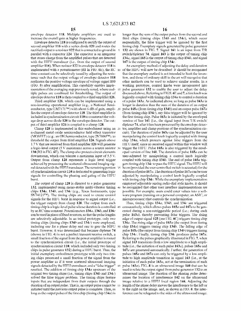
FIG. 6C
1,151
ConditionedTHger
1551.57
GatingSignal
Delay HI F -
; ( ,DN.
153 J '
FIG. 6D
111
^ Aa$
11
o Ih. 1
8N
II
o
(41
I
1
1^1
I
-----------
1
tcoOMr
T ^ N
1 II
1 NmI
I ^
11I '
1 I1 ^1IIII
11ONNIN F,
U.S. Patent Nov. 24, 2009 Sheet 8 of 16
US 7,621,873 B2
O
T
00
CN -^r r- ----------------- I1 a g^ 11 f9 y p 1
I ri b 11 U 1
^ 11 II I
__________ _____I
1^ 1
1
- 11
II' I NT---- -
QR
------ --1
IOr 'T i
1 g#
1 aM!
Nr 1
1 [q1 ,n
O ir 'n
r 1 fV O Ct
NV N
1 m1 •I a^I ^
j II1 .^1 I1 ^
1
1 ^b
1
I111
avN
ly a
r
1I ., 1
I fl 1
u '1 C ;" 1dI ^, , ^I o 1' tv W h' 11 r/ .,1 1
1 p, 1
1 q P 1
1 (-1 /1 1I 1I 1I Q 1I ^ 11 ^ 1
( O 11 a.xu 1
Si
1I p 11 N I
I N 1 co
1 d 1 V)
I „1 T
MI
I ^ 3 T T 1I
V1
1 rl .0 11 m u 1
1 r. w 11 ^ •^ 1
1 ^;, I1 ^' O I
I II1 1L ------- ----------------------1
r ------------11 a
I
1 ^11 U1 (^1 (T)
1111
i1
1
1
1 '^1
i
' N«4 g^
1 - F-11
1
1 N1 Q ^
1 }^ coa CO
I v r1 ^
1 ^ ^
1 ^
1 N
1 N
1 H
1 ?
I
LVVqII
1----------------
OMr
I
N vr 1 ^
II
I ^1 II1
I ^^ II a'
1--------- -N r---T ^ 1
' II1 W N1
6 r ^ /•, 1O rl U 1
P ? µ itC i
------------
1
1
I8 1
I11
^ 1
h' 1
^a0 I1I F 1
1
i1
- ---------------
-----------,1I
10 '1
^y1
47m I
UMr
i'Q w
I `^1
^o CO1 r
1
1
I
1
I
1
' Na ' coI
r1
1
I fa
ir
163
165
167
FIG. 7
U.S. Patent Nov. 24, 2009 Sheet 9 of 16 US 7,621,873 B2
"` r l v. 6
140
U.S. Patent Nov. 24, 2009 Sheet 10 of 16 US 7,621,873 B2
152
INPUT 150
DEVICE r154
156 x158
RAM
NON-
f 160 CPU
VOLATILEMEMORY
OUTPUT
162 J1 DEVICE
FIG. 9
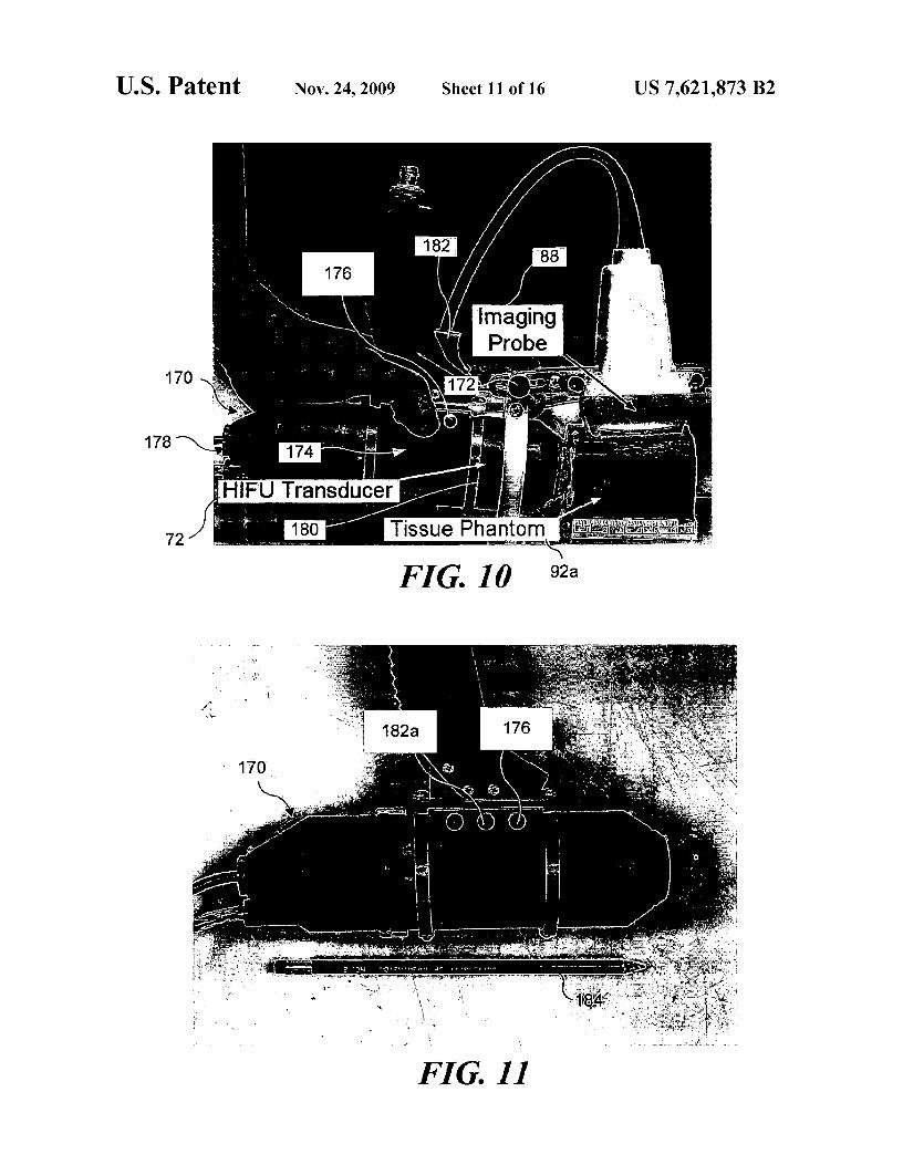
FIG. 10 92a
178
7
1'
U.S. Patent Nov. 24, 2009 Sheet 11 of 16 US 7,621,873 B2
FIG. 11
.FIG. 121
FIG. 12B
.FIG. 12C
U.S. Patent Nov. 24, 2009 Sheet 12 of 16 US 7,621,873 B2
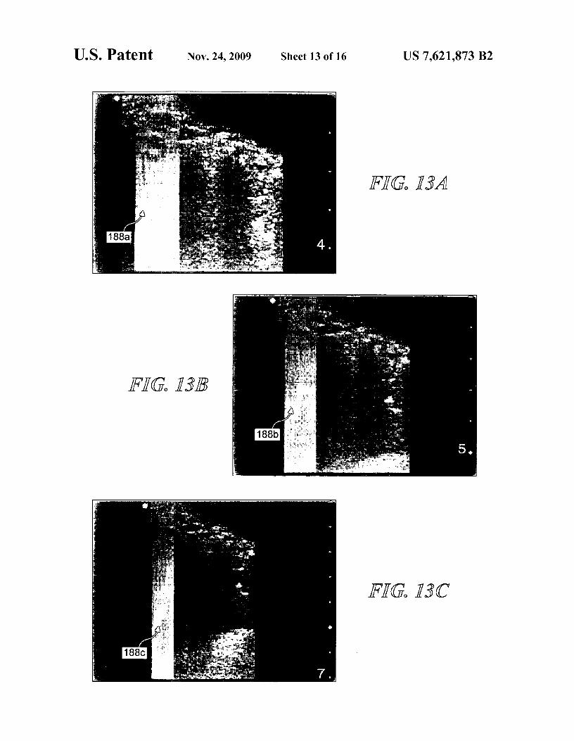
FIG. 13A
FY(G. 1313
FIG. 13C
U.S. Patent Nov. 24, 2009 Sheet 13 of 16 US 7,621,873 B2
IOVd
FIG. 14A
FIG. 14B
FIG. 14C
U.S. Patent Nov. 24, 2009 Sheet 14 of 16 US 7,621,873 B2
U.S. Patent Nov. 24, 2009 Sheet 15 of 16 US 7,621,873 B2
OD
rCD
O N
WC'noWO[V.,
a^^ II
I `'I oco
I w ^'o^w
IxI
^I
I ^ ico
xLolI ^^ I ^w I
I......_....... _^ I m ~
kn
VT
FIG® 161
FIG. 16B
U.S. Patent Nov. 24, 2009 Sheet 16 of 16 US 7,621,873 B2
^ a 2 $ >. Vim.
a E.a 6:^ i-- :3^ ^ ^, y,!ry9.^;.,^-
IT
FIG® 16C°1 ^CIA
US 7,621,873 B21
2METHOD AND SYSTEM TO SYNCHRONIZE sonic image generated is saturated with noise caused by theACOUSTIC THERAPY WITH ULTRASOUND
HIFU wave from the therapeutic transducer.
IMAGING
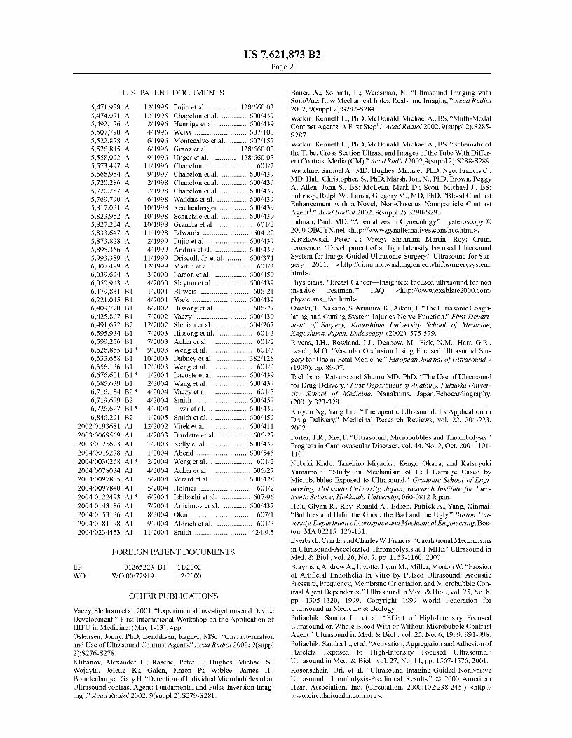
FIG. lA schematically illustrates a prior art ultrasound
image 10 in which a scanned field 12 is completely obscuredGOVERNMENT RIGHTS
5 by noise 14, caused by the simultaneous operation of an
ultrasound imaging pulse (i.e., an ultrasound imaging wave)This invention was made with U.S. Government support and a HIFU wave (neither shown). In ultrasound image 10, a
under grant No. SMS00203 awarded by NASA and the clinician may be attempting to focus the HIFU wave on aNational Space Biomedical Research Institute. The U.S. treatment site 18. However, because noise 14 completelyGovernment has certain rights in the invention. io saturates scanned field 12, it is impossible to accurately focus
the HIFU wave onto treatment site 18. If the therapy trans-FIELD OF THE INVENTION
duceris completely de-energized, noise 14 is eliminated fromthe scanned field. However, under these conditions, the focal
The present invention relates to apparatus and methods for point of the HIFU wave will not be seen, and thus, the HIFUsimultaneously using ultrasound imaging waves and ultra- 15 wave cannot be accurately focused on treatment site 18.sound therapy waves, and more specifically, to apparatus and
While some change in echogenicity at the HIFU focal point
method designed to enable real-time, noise-free ultrasound may persist for a time even after the HIFU wave is no longerimaging of a target area proximate a focal region associated active, any change in a position of the therapy transducer (orwith the ultrasound therapy waves.
treatment site 18) will not register until the therapeutic trans-2o ducer is re-energized. Thus, the HIFU wave cannot be
BACKGROUND OF THE INVENTION
focused in real time.Some prior art systems have included a targeting icon in an
Acoustic therapies include shock wave lithotripsy (SWL), ultrasound image to indicate where the known focal point ofhigh intensity focused ultrasound (HIFU), and ultrasound- a specific HIFU transducer would be located in a scannedenhanced drug delivery. HIFU is used for many therapeutic 25 image. While this icon may be helpful in determining a posi-applications, including hemostasis, tumor treatment, and tis- tion of the focal region of the HIFU transducer relative to thesue necrosis. These procedures are made possible by the scanned ultrasound image, such an icon based technique doesunique ability of such acoustic therapy technologies to selec- not enable a clinician to observe real-time results. Once thetively apply relatively large amounts of therapeutic energy HIFU therapeutic transducer is energized, the scanned ultra-(on the order of 1000 W/cm 2) to a treatment volume disposed 30 sound image is completely saturated with noise, and the cli-deep within a body mass, without adversely affecting tissue nician cannot monitor the progress of the treatment withoutdisposed between an acoustic therapy transducer that pro- again de-energizing the HIFU therapeutic transducer. Fur-duces the energy and the treatment volume. HIFU, in particu- thermore, it should be noted that the accuracy of such icon-lar, is a powerful medical technique with great potential and is based targeting systems generally degrades during treatmentcurrently being employed, both in the United States and 35 due to changes in refraction, temperature of the tissue, theabroad, to treat tumors. However, to safely implement non- presence bubbles in or near the target area, and patient move-invasive, HIFU-based transcutaneous acoustic surgery, a ment (including movement associated with respiration).medical imaging modality must be used to visualize the inter- FIG. 1B schematically illustrates a prior art technique dis-nal treatment site, for targeting the site and monitoring the closed in U.S. Pat. No. 6,425,867 (the disclosure, specifica-treatment process. Ultrasound imaging is an attractive modal- 40 tion and drawings of which are hereby specifically incorpo-ity for the following reasons: (a) images are available in rated by reference) for reducing the amount of noisereal-time; (b) portable imagers are commercially available; disrupting an ultrasound image during HIFU therapy. In FIG.(c) Doppler-based imaging modalities can be used to detect
113, the HIFU wave generated by the therapeutic transducer
bleeding; (d) ultrasound imaging is a relatively ubiquitous has been pulsed. This technique produces an ultrasoundmedical technology; and, (e) ultrasound imaging is relatively 45 image 20, in which the location of noise 24 in a scanned fieldinexpensive, compared to other medical imaging systems, 22 is a function of the interference between the pulsed HIFUsuch as magnetic resonance imaging (MRI). wave generated by the therapy transducer and the ultrasonic
A problem with combining HIFU therapy with ultrasound
imaging pulses generated by the scanning transducer. In FIG.imaging is that the high energy therapeutic waves introduces
113, noise 24 substantially masks a treatment site 28. This
a significant amount of noise into an ultrasound imaging 5o result would not occur in all cases, because to an observer,signal employed to monitor the treatment site, making simul- noise 24 would move across scanned field 22 as the interfer-taneous imaging and treatment difficult. Indeed, the high
ence between the HIFU waves and the imaging pulses varies
energy of the HIFU wave can completely overwhelm conven- in time. Pulsing of the HIFU wave alone would thus enabletional ultrasonic imaging systems. One analogy that might
the clinician to view a noise-free image of the treatment site
help to make this problem clear relates to relative intensities 55 only when noise 24 was randomly shifted to a different part ofof light. Consider the light coming from a star in the evening scanned field 22, away from the treatment site. However, suchsky to be analogous to the low power imaging ultrasound
pulsing alone generates an image that is extremely distracting
waves that are reflected from a target area toward the imaging to a clinician, because noise 24 flickers across scanned fieldtransducer, while the light from the sun is analogous to the
22, making it difficult to concentrate and difficult to consis-
HIFU waves generated by the therapy transducer. When the 60 tently determine where the focal point of the HIFU wave is,sun is out, the light from the stars is completely overwhelmed
relative to the treatment site, in real time.
by the light from the sun, and a person looking into the sky is
FIG. 1C schematically illustrates another prior art tech-unable to see any stars, because the bright light from the sun nique that is disclosed in U.S. Pat. No. 6,425,867 (referred tocompletely masks the dim light coming from the stars. Simi- hereafter as the '867 patent), also for reducing the amount oflarly, the HIFU waves emitted by the therapy transducer com- 65 noise disrupting an ultrasound image during HIFU therapy. Inpletely overwhelm the lower energy imaging ultrasound
an ultrasound image 30, a HIFU wave from a therapy trans-
waves produced by the imaging transducer, and any ultra- ducer has been both pulsed and synchronized with respect to
US 7,621,873 B23
4the ultrasonic imaging pulses from an imaging transducer, to machine to achieve modified ultrasound imaging machine 40,ensure that noise 34 does not obscure a treatment site 38. In which is capable of providing synchronization output signalultrasound image 30, noise 34 has been shifted to a location
48. The '867 patent notes that such a synchronization outputwithin a scanned field 32 that is spaced apart from treatment signal is not normally provided in prior art ultrasound imag-site 38, by selectively adjusting both the pulsing and the 5 ing machines. The '867 patent suggests that if an ultrasoundsynchronization of the HIFU wave. Preferably, noise 34 is
imaging machine capable of providing the synchronization
shifted completely away from treatment site 38, thus provid- output signal is not available, then a synchronization outputing the clinician a noise-free, stable image of treatment site 38 signal can be derived from the ultrasound imaging signalsthat clearly shows the location of the focal point of the HIFU
conveyed by cable 42. The '867 patent also suggests that an
wave relative to the treatment site. Thus, the HIFU wave can io optional stable synchronization signal generator 66 can bebe focused onto treatment site 38, in real time. By synchro- used to synchronize the HIFU wave to the imaging ultrasonicnizing the HIFU bursts within each imaging frame, the inter- wave, instead of using synchronization output signal 48 fromference can be relegated to certain portions of the image, such
ultrasound imaging machine 40. Stable synchronization sig-
as a fringe of the ultrasound image, enabling other portions of
nal generator 66 can be used to provide a stable synchronizingthe ultrasound image to remain useful for monitoring and 15 pulse to initiate the HIFU wave, and the timing of this stableguidance. If the imaging process and the HIFU bursts are not synchronizing pulse can be manually varied until a noise-freesynchronized, the interference will randomly obscure the
image of the treatment site has been obtained. A drawback of
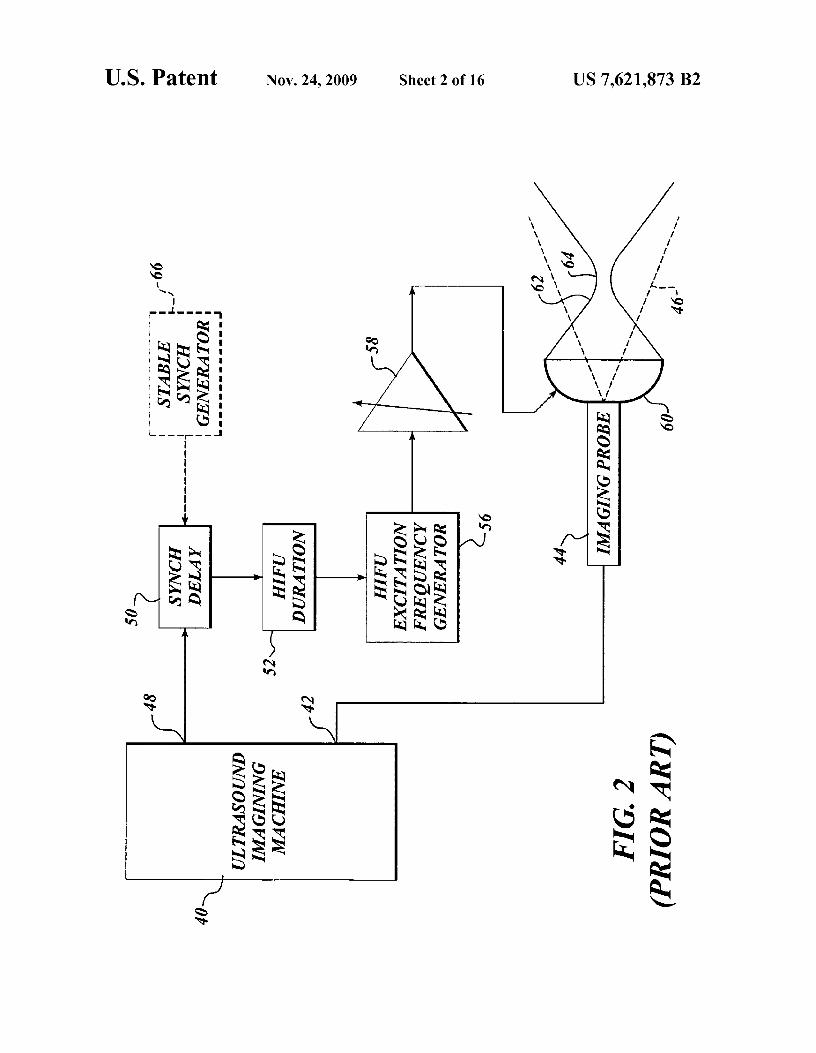
treatment site, as indicated in FIG. 1B. using stable synchronization signal generator 66 instead ofFIG. 2 is a block diagram from the '867 patent, schemati- synchronization output signal 48 is that any change in the
cally illustrating a system that synchronizes the ultrasound 20 timing of the ultrasound imaging pulses, such as is required toimage and HIFU waves required for the simultaneous imag- scan deeper within tissue, will require to the user to againing and therapy in real time. A conventional imaging probe 44
adjust stable synchronization signal generator 66. Such an
is connected to an ultrasound imaging machine 40 via a cable adjustment would not be required if synchronization output42. Imaging probe 44 generates ultrasonic imaging pulses signal 48 were used. It should be noted that one drawback ofthat propagate to the target area, are reflected from structure 25 using synchronization output signal 48 is that the ultrasoundand tissue within the body, and are received by the imaging
imaging system must be modified or custom built to provide
probe. The signal produced by the imaging probe in response such a synchronization signal. Furthermore, some imagingto the reflected ultrasound imaging waves is communicated to modalities, such as Doppler imaging, have very complexthe ultrasound imaging machine through cable 42 and pro- signals, and synchronization output signal 48 may not be verycessed to provide a visual representation of the structure and 30 effective for synchronizing such complex signals.tissue that reflected the ultrasonic imaging pulses. An imag- Essentially, the '867 patent addresses HIFU interference ofing beam sector 46 (indicated by dotted lines) from imaging ultrasound imaging by synchronizing the interference so thatprobe 44 is identified in the Figure by dash lines. The system the interference is stable and is located at the fringes of thedescribed in the '867 patent also includes a therapeutic trans- image. As a result, the region of interest in the image is notducer 60. When excited, this therapeutic transducer generates 35 obscured (as is schematically indicated in FIG. 1C). ThisHIFU waves that are focused at a particular point of interest, functionality requires knowledge of the frame rate and phasei.e., a treatment site within a patient's body. In FIG. 2, the path
of the imaging cycle, both of which vary with changes to user
of a HIFU beam 62 (indicated by solid lines) narrows to a control settings (particularly depth and switching modalityfocal point 64. from b-mode to Doppler). Once the frame rate and phase are
Synchronization output signal 48 is supplied to a synchro- 4o known, HIFU can be gated synchronously with the imagingnization delay 50, which enables the user to selectively vary cycle and the interference that is caused can be moved to thethe initiation of each HIFU wave with respect to each
fringes of the image. Unfortunately, there is no simple way of
sequence of ultrasonic imaging pulses that are generated to
determining the frame rate and phase of a stand-alone com-form an ultrasonic image. Referring to FIG. 1C, delay 50 mercial imager that has not been designed to provide suchenables a user to vary the position of noise 34 in scanned field 45 information (i.e., which has not been modified to provide32, so that the noise is moved away from treatment site 38, to synchronization output signal 48).a different portion of scanned field 32. A HIFU duration
As indicated in the '867 patent, ultrasound imaging sys-
circuit 52 is used to control the duration of the HIFU wave. A
tems can be designed to incorporate a synchronization outputlonger duration HIFU wave will apply more energy to the signal. However, even though ultrasound imaging systemstreatment site. If the HIFU wave is too long, the duration of 5o are significantly less expensive than MRI imaging systems,noise 34 as shown in ultrasound image 30 will increase and
high end ultrasound imaging systems can still cost in excess
can extend into the next ultrasound imaging pulse to obscure of $150,000, and it would be desirable to provide a synchro-treatment site 28, or may completely obscure ultrasound
nization technique that is compatible with ultrasound imag-
image 30, generating a display very similar to ultrasound
ing systems that do not provide a synchronization outputimage 10 in FIG. 1A. Thus, the user will have to selectively 55 signal (the majority of ultrasound imaging systems sold do(i.e., manually) adjust HIFU duration circuit 52 to obtain a not support the synchronization output signal as described innoise-free image of treatment site 38, while providing a suf- the '867 patent). The '867 patent also suggests that the syn-ficient level of energy to the treatment site to affect the desired
chronization signal (frame rate without phase information)
therapeutic effect in an acceptable time. A HIFU excitation could be obtained from the cable coupling an ultrasoundfrequency generator 56 is used to generate the desired fre- 60 imaging probe to ultrasound imaging machines. This theo-quency for the HIFU wave, and a power amplifier 58 is used
retically could be achieved by detecting current in the cable.
to amplify the signal produced by the HIFU excitation fre- However, such cables include many wires and currents, andquency generator to achieve the desired energy level of the such cables are well shielded to meet safety standards. Hence,HIFU wave. Power amplifier 58 is thus adjustable to obtain a obtaining the signal necessary for synchronization from adesired energy level for the HIFU wave. 65 shielded cable is challenging. The cable could be modified to
Significantly, the system disclosed in the '867 patent
facilitate extraction of the synchronization signal; however,requires modifying a conventional ultrasound imaging that modification is not likely to be supported by the manu-
US 7,621,873 B25
facturers of the ultrasound imaging equipment, and operatorsof medical equipment are not likely to pursue a modificationnot sanctioned by a manufacturer, particularly because ofliability and warranty concerns. Thus, it wouldbe desirable toprovide a technique for synchronizing HIFU interference inan ultrasound image, without requiring the use of a stablesynchronization signal generator as disclosed in the '867patent. The synchronization should also be achieved withoutmodifying an ultrasound imaging apparatus to provide a syn-chronization signal.
SUMMARY OF THE INVENTION
The present invention encompasses systems and methodsfor enabling a HIFU transducer to be synchronized to anultrasound imaging system, to facilitate ultrasound imageguided HIFU therapy. As noted above in the Background ofthe Invention, the ' 867 patent discloses that HIFU transducerscan be readily synchronized to ultrasound imaging systemswhen the ultrasound imaging system has been modified toprovide a synchronization signal. The present inventionfacilitates synchronization of a HIFU transducer and an ultra-sound imaging system without requiring the ultrasound imag-ing system itself to provide a separate synchronization signal.Most commercial ultrasound imaging systems do not providea separate synchronization signal, and as a result, implement-ing the synchronization technique disclosed in the '867 patentcan require modifying existing ultrasound imaging systems.However, a preferred embodiment of the present inventionenables gating HIFU synchronously with ultrasound imagingwithout requiring a customized ultrasound imaging system.An aspect of this embodiment is utilizing a HIFU transduceras a receiver, to detect scattered ultrasound waves generatedby the ultrasound imaging system, so that the scattered ultra-sound imaging wave received by the HIFU transducer can beused to synchronize the HIFU transducer to the ultrasoundimaging system. Alternatively, a separate, dedicated receivercould be used to receive scattered ultrasound imaging waves(instead of using the HIFU transducer as a receiver); however,using the HIFU transducer as a receiver is an elegant solution.Particularly, when an ultrasound imaging transducer and aHIFU transducer are coplanar (such a configuration facili-tates visualization of the treatment process), or coaxial, it ispossible to use the HIFU transducer as a focused receiver todetect scattered ultrasound imaging waves from the ultra-sound imaging transducer. The scattered ultrasound imagingwaves received by the HIFU transducer can then be processedto provide a control signal to be used in energizing the HIFUtransducer, the control signal being synchronized with theultrasound imaging waves to reduce the amount of interfer-ence introduced into the ultrasound image by the HIFUwaves.
In one embodiment, the processing of the scattered ultra-sound imaging waves received by the HIFU transducer (or adedicated receiver) is achieved using a computing device. Inanother embodiment, the processing of the scattered ultra-sound imaging waves received by the HIFU transducer (or adedicated receiver) is achieved by a hard-wired circuit. Thisapproach enables synchronization to be achieved withoutcustomizing an ultrasound imaging system to provide a sepa-rate synchronization signal, and without cataloging andreproducing frame rates with a function generator (a tech-nique that is also described in the '867 patent).
The approach described herein can be implemented when-ever the ultrasound imaging transducer and the HIFU trans-ducer are both coupled to a medium that scatters the ultra-sound imaging waves. Most tissue targeted during HIFU
6therapy will provide sufficient scattering. Note that if a sepa-rate receiver is used to collect the scattered ultrasound imag-ing waves, as opposed to using the HIFU transducer to collectthe scattered ultrasound imaging waves, the separate receiver
5 will similarly need to be coupled to the medium that scattersthe ultrasound imaging waves.
Another aspect of the present invention is directed to auto-matically determining the frame rate and phase of an ultra-sound imager in real time and employing the frame rate to
10 dynamically trigger the application of high intensity ultra-sound therapy. Consequently, as a user adjusts the controls ofthe imager, the ultrasound therapy not only remains synchro-nized with the frame rate, but also remains in phase, so that theHIFU waves only obscure regions outside the area of interest
15 in the imaging display.
BRIEF DESCRIPTION OF THE DRAWINGSFIGURES
20 The foregoing aspects and many of the attendant advan-tages of the various embodiments discussed below willbecome more readily appreciated as the same becomes betterunderstoodby reference to the following detailed description,when taken in conjunction with the accompanying drawings,
25 wherein:FIGS. 1A-1C (all depicting Prior Art) respectively illus-
trate ultrasonic images generated during the simultaneous useof ultrasound for imaging and therapy, the pulsing of the
30 HIFU in a conventional scanned image, and the synchronizedpulsing of the HIFU and the scan image so as to shift the noiseaway from a displayed treatment site;
FIG. 2 (Prior Art) is a block diagram illustrating the com-ponents of an earlier system that is capable of synchronizing
35 HIFU therapy in ultrasound imaging, which requires themodification of commercially available ultrasound imagingequipment to achieve a synchronization signal;
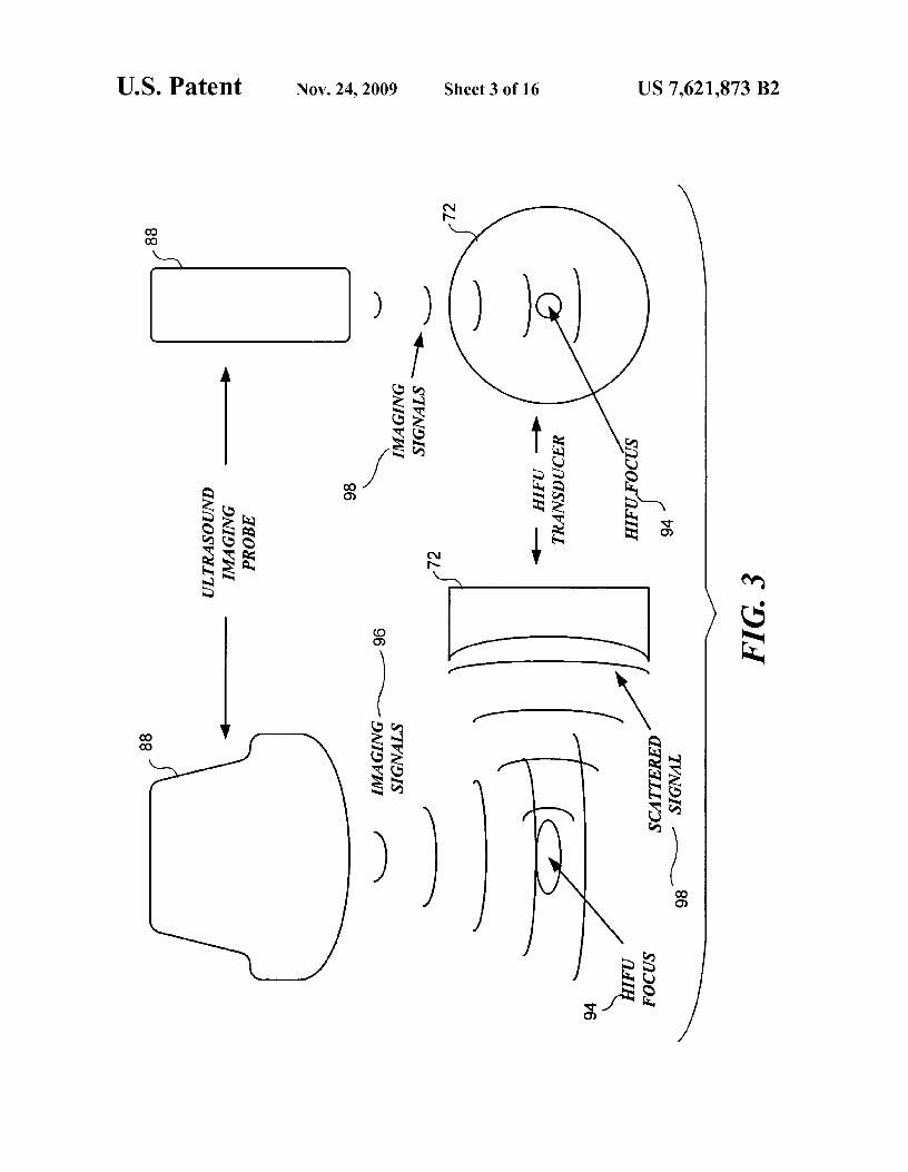
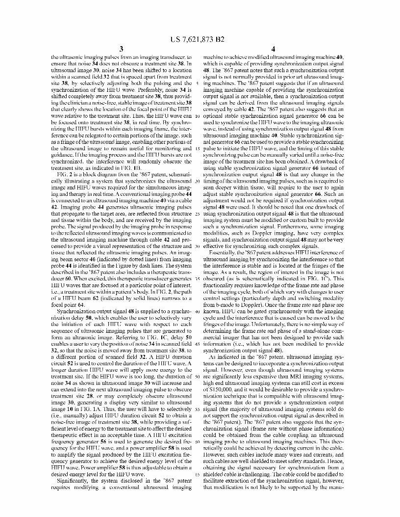
FIG. 3 schematically illustrates using a therapy transduceras a receiver to detect imaging signals from an ultrasound
40 imaging transducer, in accord with one embodiment of thepresent invention;
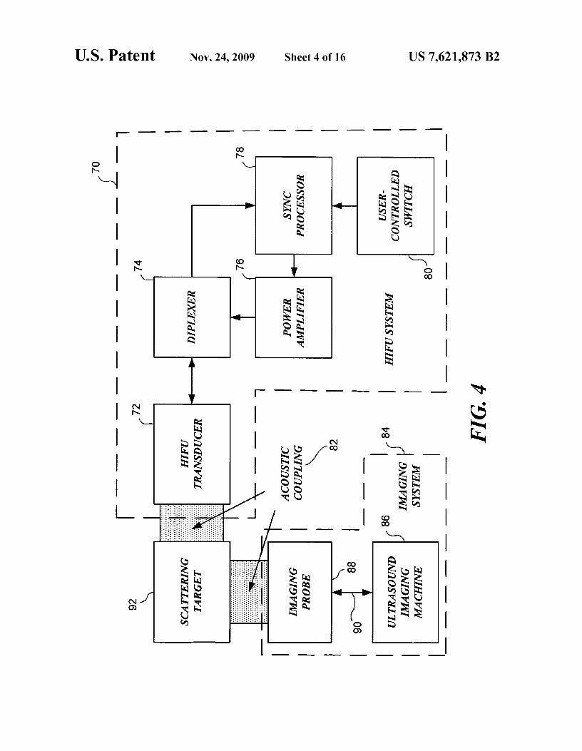
FIG. 4 is a block diagram illustrating one embodiment ofthe present invention, which enables an ultrasound imagingsystem to be synchronized with a HIFU therapy system, with-
45 out requiring the ultrasound imaging system to provide asynchronization signal;
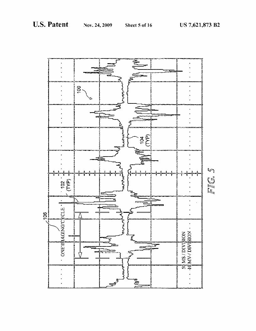
FIG. 5 graphically illustrates an exemplary voltage signalthat is generated by detecting B-mode imaging signals with aHIFU transducer;
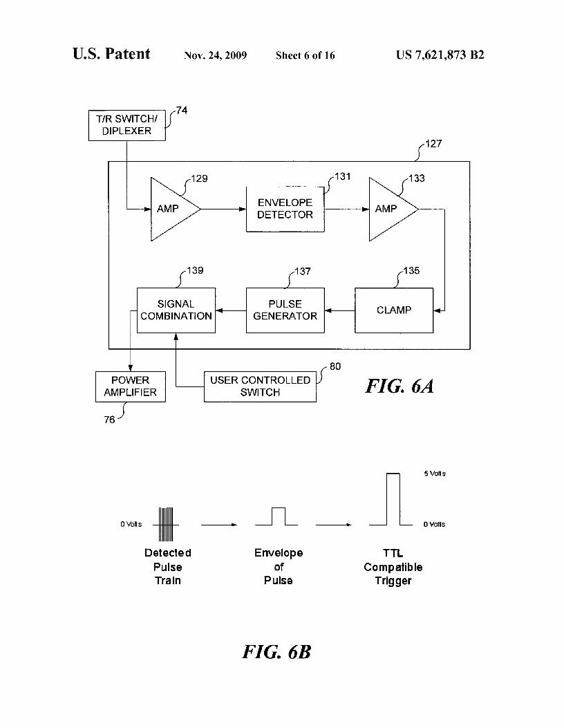
50 FIG. 6A schematically illustrates a basic synchronizationcircuit for implementing the synchronization processor ofFIG. 4;
FIG. 6B schematically illustrates a basic portion of thesignal conditioning performed by the synchronization circuit
55 of FIG. 6A;FIG. 6C and 6D graphically illustrate exemplary signals
associated with the synchronization circuit of FIG. 6A;FIG. 6E schematically illustrates an exemplary synchroni-
60 zation circuit used to implement the synchronization proces-sor of FIG. 4 in one embodiment of the present invention;
FIG. 7 graphically illustrates an exemplary synchroniza-tion signal generated by the synchronization circuit of FIG. 6;
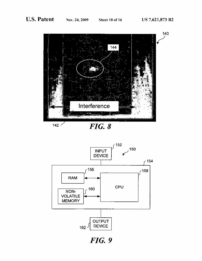
FIG. 8 is an ultrasound image in which interference from65 HIFU waves has been shifted to fringes of the ultrasound
image, enabling a focal region of the HIFU beam to be visu-alized in the ultrasound image;
US 7,621,873 B27
8FIG. 9 schematically illustrates an exemplary computing waves as a "beam," much in the way the science of optics
system used to implement the synchronization processor of
refers to light as a beam, even though light exhibits aspects ofFIG. 4 in another embodiment of the present invention;
both waves and particles. This dual nature is particularly true
FIGS. 10 and 11 are photographs of a prototype HIFU
with respect to HIFU waves, because HIFU waves can besystem tested in conjunction with the exemplary synchroni- 5 focused much in the way that light can be focused (i.e., a focalzation circuit of FIG. 6E; point is associated with HIFU waves, and the focal point
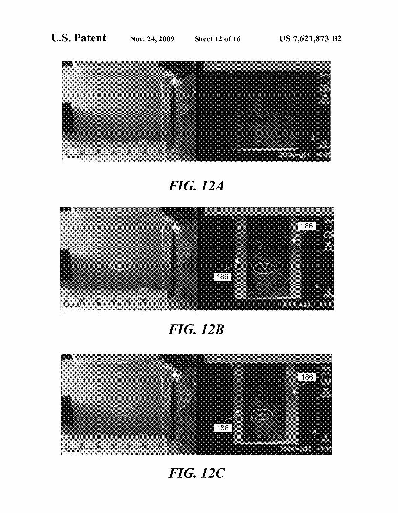
FIGS. 12A-12C are composite images, each respectively corresponds to a region where the HIFU waves are capable of
including both a photograph of a gel tissue phantom and an
delivering a maximum amount of acoustic energy).
ultrasound image, ultrasound each image representing vari- The term "signal" is often used in the electronic arts to referous stages of the application of HIFU waves to the gel tissue io to an impulse or a fluctuating electric quantity, such as volt-phantom; age, current, or electric field strength, whose variations con-
FIGS. 13A-13C are ultrasound images generated using vey information. It should be understood that as used herein,
synchronization techniques in accord with one embodiment, ultrasound waves, particularly ultrasound imaging waves,
wherein noise in each ultrasound image due to simultaneous can be considered to be a signal. Thus, ultrasound imagingHIFU application has been shifted to the fringes of the ultra- 15 waves generated by an ultrasound imaging transducer are atsound image; times referred to in the following discussion as a signal. The
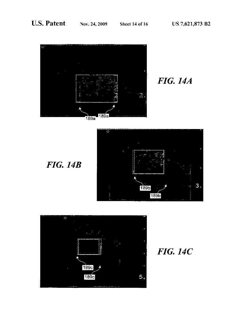
FIGS. 14A-14C are ultrasound images generated using term "synchronization signal," as used in the following dis-
synchronization techniques provided by one exemplary closure and the claims that follow, is to be understood to mean
embodiment, wherein noise in each ultrasound image due to an impulse or a fluctuating electric quantity, such as voltage,simultaneous HIFU application has been shifted to the fringes 20 current, or electric field strength, whose variations conveyof the ultrasound image;
information that can be used to synchronize pulses of HIFU
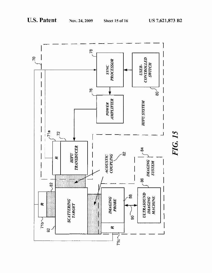
FIG. 15 is a block diagram illustrating an embodiment in waves with pulses of ultrasound imaging waves, so that inter-
which a dedicated receiver is employed to detect scattered
ference from the HIFU waves in an ultrasound image gener-
ultrasound imaging waves, producing a signal for processing ated using the ultrasound imaging waves can be reduced, orby a synchronization processor to enable a HIFU transducer 25 shifted to a portion of the ultrasound image that does not
to be synchronized with an ultrasound imaging transducer;
interfere with a particular area of interest in the ultrasoundand
image.
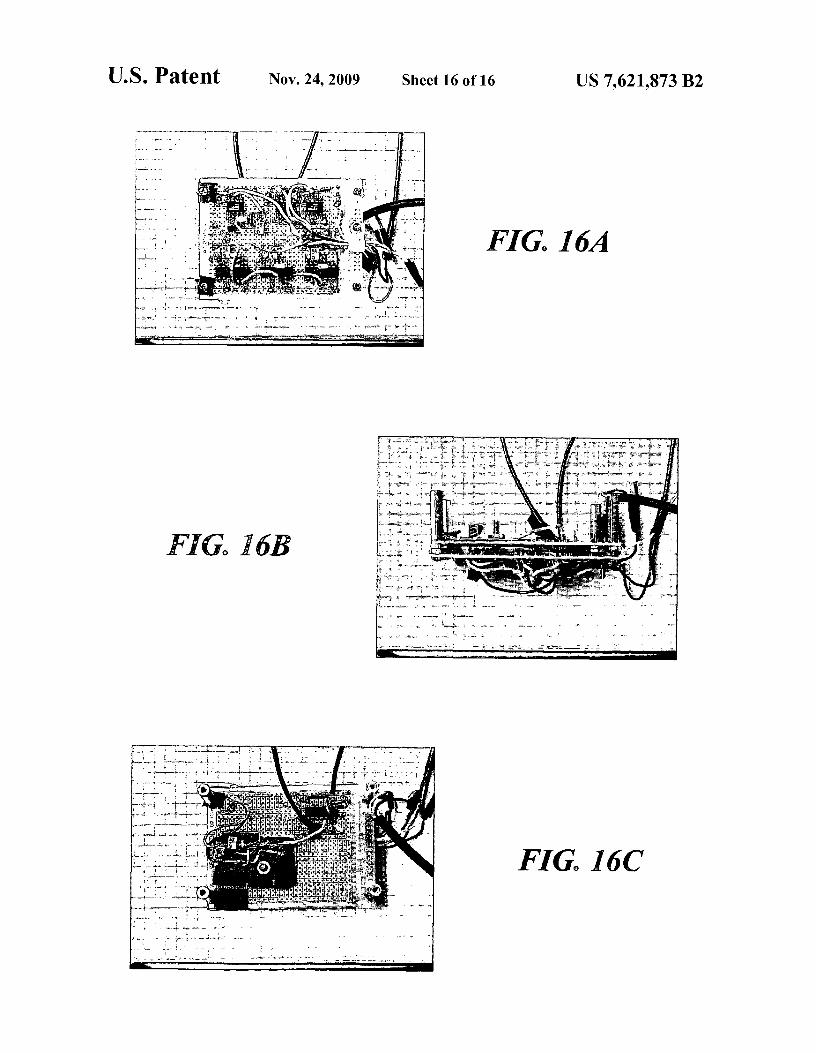
FIGS. 16A-16C illustrate an exemplary working prototype
To form an imaging frame, array elements in an ultrasoundof a synchronization circuit. imaging probe transmit and receive acoustic waves according
30 to a pattern that is determined by the manufacturer of theDESCRIPTION OF THE PREFERRED ultrasound imaging system. This pattern usually includes
EMBODIMENT some "quiet time," during which the received signals (i.e.,reflected ultrasound imaging waves) are processed by the
Prior art HIFU/imaging ultrasound synchronization tech- ultrasound imaging system to generate an ultrasound image.niques have relied on modification of the ultrasound imaging 35 The frame rate, which is independent of the video frame rate
system to provide a synchronization signal to react to operator (often available in NTSC format through an external connec-
controlled adjustments, such as image depth, to maintain tor), depends on several factors, including: imaging depth,
synchronization between the HIFU system and the ultrasound
imaging modality, and the signal processing capabilities of
imaging system. Embodiments of the present invention facili- the ultrasound imaging system.tate HIFU/imaging ultrasound synchronization with an arbi- 40 In accord with one exemplary embodiment of the present
trary, unmodified ultrasound imaging system (i.e., an ultra- invention, a HIFU transducer can be used as a focused
sound imaging system not modified to provide a receiver, to detect scattered ultrasound imaging waves gener-
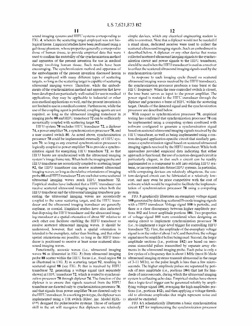
synchronization signal). Empirical studies indicate that ated by the ultrasound imaging probe. This concept is sche-
embodiments of the present invention facilitates ultrasound matically illustrated in FIG. 3. An ultrasound imaging probeimage guided application of HIFU using both Doppler and 45 88 (including an ultrasound imaging transducer, not sepa-
B-mode ultrasound imaging systems. The ability of the rately shown) produces pulses of ultrasound imaging waves
present invention to be used in connection with Doppler 96 directed towards a target region. A HIFU transducer 72 is
imaging is significant, as Dopplerimagingis crucial forblood positioned such that a focal region 94 of the HIFU transducer
flow imaging. Doppler imaging has a significantly more com- lies within an image plane corresponding to ultrasound imag-plicated signal pattern than B-mode imaging, and synchroni- 50 ing probe 88 (i.e., focal region 94 lies within the path of
zation of HIFU therapy with Doppler imaging requires more ultrasound imaging waves 96). Some portion of the ultra-
data to achieve stable synchronization than is required to sound imaging waves is reflected back towards ultrasound
achieve stable synchronization with B-mode imaging. imaging probe 88. Those ultrasound imaging waves are used
Embodiments of the present invention have been successfully by the ultrasound imaging system to generate an ultrasoundtested for compatibility with both Doppler imaging and 55 image. Another portion of the ultrasound imaging waves areB-mode imaging. reflected away from ultrasound imaging probe 88. Some por-
The terms "therapeutic transducer," "HIFU transducer,"
tion of the ultrasound imaging waves that are reflected away
and "high intensity transducer," as used herein and in the
from ultrasound imaging probe 88 are reflected towards
claims that follow all refer to a transducer that is capable of
HIFU transducer 72, as indicated by scattered signal 98.being energized to produce ultrasonic waves that are much 6o Because the HIFU transducer is most sensitive to imaging
more energetic than the ultrasonic waves produced by an signals that scatter from within its focus, and since the longi-
imaging transducer, and which can be focused or directed
tudinal cross-section of the HIFU focus is small compared to
onto a discrete location, such as a treatment site in a target
the sector width of a typical diagnostic ultrasound imaging
area. The term "HIFU beam" should be understood to refer to probe, the signal received by the HIFU transducer containsa characteristic pattern of HIFU waves emitted from a HIFU 65 two types of information that can be used to achieve synchro-
transducer. Ultrasound is a wave-based phenomenon; how- nization, including: (1) the imaging frame rate, and (2) the
ever, those of ordinary skill in the art often refer to HIFU
phasing of the imaging cycle. If the pulse repetition frequency
US 7,621,873 B29
10of the HIFU burst is controlled to be equal to the imaging sound imaging system and collected by the HIFU system.frame rate, then the interference will appear in the same place
That is, in an alternative embodiment, the HIFU system could
in each ultrasound image generated by the ultrasound imag- be logically coupled with a processor configured to generateing system. If the start of the HIFU burst is delayed from the a synchronization signal used to gate HIFU bursts based ontime at which the scattered ultrasound imaging waves (i.e., 5 scattered ultrasound imaging waves generated by the ultra-scattered signal 98) are detected, then the interference will not sound imaging system and collected by the HIFU transducer.obscure the treatment site within the ultrasound image, Thus, while the embodiment schematically illustrated in FIG.although a different (less critical) portion of the ultrasound
4 represents one preferred embodiment, it should be under-
image will be sacrificed (i.e., a different portion of the ultra- stood that FIG. 4 is not intended to limit the invention, par-sound image will be subject to interference from the HIFU io ticularly because the synchronization processor could bewaves). implemented as a component not contained within the HIFU
The imaging frame rate is important for synchronization, system. Of course, where the HIFU transducer is used tobut the value of the imaging frame rate is not used explicitly collect the scattered ultrasound imaging signals to be pro-in this exemplary embodiment of the present invention. That cessed to generate a synchronization signal, the HIFU trans-is, the frame rate is not measured, and the value of the imaging 15 ducer will be logically coupled to the synchronization pro-frame rate is not used in a calculation to generate the synchro- cessor, even if the synchronization processor is implementednization signal that gates the HIFU burst. Because imaging outside of the HIFU system.signals from each imaging cycle are detected, and because the
The synchronization can be achieved by using HIFU trans-
synchronization signal controlling the HIFU gating is gener- ducer 72 as a receiver, to detect scattered ultrasound imagingated in response to the detected scattered ultrasound imaging 20 waves signals generated by an ultrasound imaging transducersignals (i.e., scattered signal 98), the HIFU burst will be
(not separately shown) that is included in an ultrasound imag-
repeated at the imaging frame rate. As a result, it is not
ing probe 88. The synchronization enables the ultrasoundnecessary to measure or specify the frame rate, and, further, imaging system to be operated continuously, while noisethe system and method employed in this technique can adapt corresponding to HIFU waves is shifted away from a regioninstantly when imager settings that affect the imaging frame 25 of interest within an ultrasound image produced by ultra-rate are changed. For example, when either the imaging depth
sound imaging machine 86.
or the imaging modality is changed, the imaging frame rate is
Note that ultrasound imaging system 84 is intended toalso changed, but the HIFU burst will remain synchronized
represent conventional and commercially available ultra-
using the system and method of the embodiments discussed
sound imaging systems. Such conventional ultrasound imag-herein. Thus, a scattered ultrasound imaging signal detected 30 ing systems include an imaging probe (i.e., imaging probe 88)with the HIFU transducer can be processed into a trigger that
that generates ultrasound imaging waves, which propagate
controls a HIFU burst that is inherently synchronized with the
from the imaging probe to the target area. Such ultrasoundimaging cycle. imaging waves are reflected by structure and tissue within the
Note that if the HIFU transducer is positioned such that the
body. Some of the reflected ultrasound imaging waves arefocal region of the HIFU transducer is disposed outside of the 35 then received by the imaging probe. An electrical signal pro-imaging plane corresponding to the ultrasound imaging
duced by the imaging probe in response to the reflected ultra-
probe, it is likely that some scattered ultrasound imaging sound imaging waves is communicated to the ultrasoundsignals may still be received by the HIFU transducer. How- imaging machine (i.e., ultrasound imaging machine 86)ever, positioning the HIFU transducer (or a therapy probe through a cable (i.e., cable 90) and processed to provide aincorporating the HIFU transducer) relative to the ultrasound 40 visual representation of the structure and tissue that reflectedimaging probe such that the focal region of the HIFU trans- the ultrasonic imaging pulses. Many ultrasound imagingducer does lie within the imaging plane of the ultrasound
machines include an integrated monitor for display of the
imaging probe is particularly preferred, because such an ori- ultrasound image, or a separate monitor (not separatelyentation will enable the focal region of the HIFU transducer to shown) can be employed. Significantly, FIG. 4 represents abe visualized in the ultrasound image when both the ultra- 45 HIFU system that can be used with any arbitrary ultrasoundsound imaging transducer in the HIFU transducer are ener- imaging system (i.e., the ultrasound imaging systemgized in a synchronized fashion. Enabling the focal region of
employed does not need to be modified to provide a synchro-
the HIFU transducer to be visualized in an ultrasound image nization signal used to drive the HIFU system).represents a significant benefit of the present invention. When ultrasound imaging systems are used to generate an
A high-level functional block diagram of one embodiment 50 ultrasound image of an internal treatment site in a patient, anfor implementing the present invention is provided in FIG. 4. acoustic coupling is frequently disposed in between the ultra-As demonstrated in FIG. 4, the synchronization of a HIFU
sound imaging probe and the patient's skin layer, to enhance
therapy system 70 with an ultrasound imaging system 84 can the acoustic coupling of the ultrasound imaging waves to thebe achieved without requiring any electrical connection patient's tissue. Many different types of acoustic couplers canbetween the HIFU therapy system and the ultrasound imag- 55 be used, including coupling gels and semi solid hydrogel-ing system. Significantly, all synchronization signal process- based couplers. Referring to FIG. 4, an acoustic coupling 82ing occurs outside the ultrasound imaging system, and the
is preferably employed to acoustically couple imaging probe
only information required from the ultrasound imaging sys- 88 to a scattering target 92. In general, scattering target 92 willtem is a scattered ultrasound imaging wave (i.e., an acoustic
be a patient (i.e., biological tissue), because one of the most
imaging signal generated by the ultrasound imaging system, 60 widespread applications of ultrasound image guided HIFU isportions of which are of used by the ultrasound imaging
for medical therapy, although it should be understood that the
system to generate an ultrasound image). While in one pre- present invention is not limited to the synchronization offerred embodiment (the embodiment schematically illus- HIFU with ultrasound imaging solely in a medical context.trated in FIG. 4) the signal processing occurs within the HIFU
The same principles disclosed herein could be used to simul-
system, it should be understood that signal processing could 65 taneously image and apply HIFU to other types of scatteringalternatively occur externally of the HIFU system, based on a targets (i.e., scattering targets other than biological tissue).scattered ultrasound imaging wave generated by the ultra- Indeed, empirical studies have been performed using ultra-
US 7,621,873 B211
12sound imaging systems and HIFU systems corresponding to simple devices, which any electrical engineering student isFIG. 4, wherein the scattering target employed was not bio- able to construct. Note that a diplexer would not be needed iflogical tissue. Empirical studies have been performed using a a stand alone, dedicated receiver were used to collect thegel tissue phantom, whose properties generally correspond to scattered ultrasound imaging signals. Such an embodiment isthose of human tissue, to provide empirical data that were 5 described below. A diplexer, or any other device that routesused to confirm the suitability of the synchronization method
collected scattered ultrasound imaging signals to the synchro-
and apparatus of the present invention for use in medical
nization circuit and power signals to the HIFU transducer,therapy involving human tissue. Such results have been should be used when the HIFU transducer is used as a receiverencouraging. The synchronization method and apparatus of
to collect the scattered ultrasound imaging signals used by the
the embodiments of the present invention discussed herein io synchronization circuit.can be employed with many different types of scattering
In response to each imaging cycle (based on scattered
targets, so long as the scattering target is capable of scattering ultrasound imaging waves received by the HIFU transducer),ultrasound imaging waves. Therefore, while the embodi- the synchronization processor produces a tone burst at thements of the synchronization method and apparatus that have
HIFU frequency. When the user-controlled switch is closed,
been developed are particularly well-suited for use in medical 15 the tone burst serves as input to the power amplifier. Theapplications, they may be applicable to industrial or other power signal is routed to the HIFU transducer through thenon-medical applications as well, and the present invention is
diplexer and generates a burst of HIFU within the scattering
not limited to use in a medical context. Furthermore, while the target. Details of the detected signal and the synchronizationuse of the coupling agent is preferred, coupling agents are not processor are described below.required, so long as the ultrasound imaging transducer in 20 With respect to synchronization processor 78, empiricalimaging probe 88 and HIFU transducer 72 can be sufficiently testing has confirmed that synchronization processor 78 canacoustically coupled with scattering target 92. be implemented using a computing system combined with
HIFU system 70 includes HIFU transducer 72, a diplexer software configured to generate a synchronization signal74, a power amplifier 76, a synchronization processor 78, and
based on scattered ultrasound imaging signals received by the
a user control switch 80. As noted above, synchronization 25 HIFU transducer, as well as being implemented using a cus-processor 78 could be implemented externally of HIFU sys- tom-designed application-specific circuit that similarly gen-tem 70, so long as any external synchronization processor is erates a synchronization signal based on scattered ultrasoundlogically coupled to power amplifier 76 to provide a synchro- imaging signals received by the HIFU transducer. While bothnization signal for energizing HIFU transducer 72, so that approaches provided empirical data indicating that eitherHIFU bursts are synchronized with the ultrasound imaging 3o approach is functional, the use of a custom-designed circuit issystem's image frame rate. When both the imaging probe and
particularly elegant, in that such a circuit can be readily
HIFU transducer are acoustically coupled to scattering target
implemented as a component to add into existing HIFU sys-92, the HIFU transducer can receive scattered ultrasound
tems, or incorporated into future HIFU systems. In particular,
imaging waves, so long as the relative orientations of imaging while computing devices are relatively ubiquitous, the cus-probe 88 and HIFU transducer 72 are suchthat some scattered 35 tom-designed circuit can be fabricated at a relatively low-ultrasound imaging waves reach HIFU transducer 72. cost, and may even be price competitive with the cost ofEmpirical studies have indicated that a HIFU transducer can software which would be required to facilitate the implemen-receive scattered ultrasound imaging waves when both the tation of synchronization processor 78 using a computingHIFU transducer and the ultrasound imaging transducer gen- system.erating the ultrasound imaging waves are acoustically 40 FIG. 5 graphically illustrates an exemplary voltage signalcoupled to the same scattering target, and the HIFU trans- 100 generatedby detecting scattered B-mode imaging signalsducer and the ultrasound imaging transducer are generally with a HIFU transducer. Voltage signal 100 is periodic, andcoplanar, or coaxial. Empirical studies have also indicated
there is a clear discrepancy between higher amplitude por-
that disposing the HIFU transducer and the ultrasound imag- tions 102 and lower amplitude portions 104. Two propertiesing transducer at a spatial orientation of about 90° relative to 45 of voltage signal 100 were considered when designing aneach other can facilitate enabling the HIFU transducer to analog circuit to implement synchronization processor 78receive scattered ultrasound imaging waves. It should be
(i.e., to implement a logic-level trigger for controlling HIFU
understood, however, that such a spatial orientation is transducer 72). First, the amplitude of the exemplary voltageintended to be exemplary, rather than limiting, and that other signal is on the order of about 1 mV, and therefore, the voltagespatial orientations are possible, so long as the HIFU trans- 50 signal must be amplified before being used. Second, the largerducer is positioned to receive at least some scattered ultra- amplitude sections (i.e., portions 102) are based on zero-sound imaging waves. mean sinusoidal pulses transmitted by separate array ele-
Functionally, acoustic waves (i.e., ultrasound imaging ments in the ultrasound imaging probe. Each pulse is only awaves 96 as illustrated in FIG. 3) from ultrasound imaging
few cycles of a frequency that is about 1 MHz (most B-Mode
probe 88 scatter within the HIFU focus (i.e., focal region 94 55 ultrasound imaging systems transmit ultrasound in the rangeas illustrated in FIG. 3) in scattering target 92, resulting in of 3-11 MHz), so the pulse length is less than a few micro-scattered signal 98 (see FIG. 3) that is received by HIFU
seconds. The higher amplitude pulses are separated by peri-
transducer 72, generating a voltage signal (not separately ods of zero amplitude (i.e., portions 104) that last for hun-shown) at HIFU transducer 72, which is routed to synchroni- dreds of microseconds, during which the ultrasound imagingzation processor 78 through diplexer 74. The function of the 60 system is collecting echo data. Empirical studies have showndiplexer is to ensure that signals received from the HIFU
that a logic-level trigger can be generated reliably by ampli-
transducer are directed only to synchronization processor 78, fying voltage signal 100, averaging the high amplitudes por-and that signals from power amplifier 76 are directed only to tions (i.e., portions 102), and then applying a voltage thresh-the HIFU transducer. In a working prototype, the diplexer was old to eliminate amplitudes that might represent noise andimplemented using a T/R switch (Ritec, Inc. Model RDX- 65 should be excluded.6TM) designed for pulse/receive systems. Those of ordinary
FIG. 6A schematically illustrates a basic synchronization
skill in the art will recognize that diplexers are relatively circuit 127 for implementing the synchronization processor
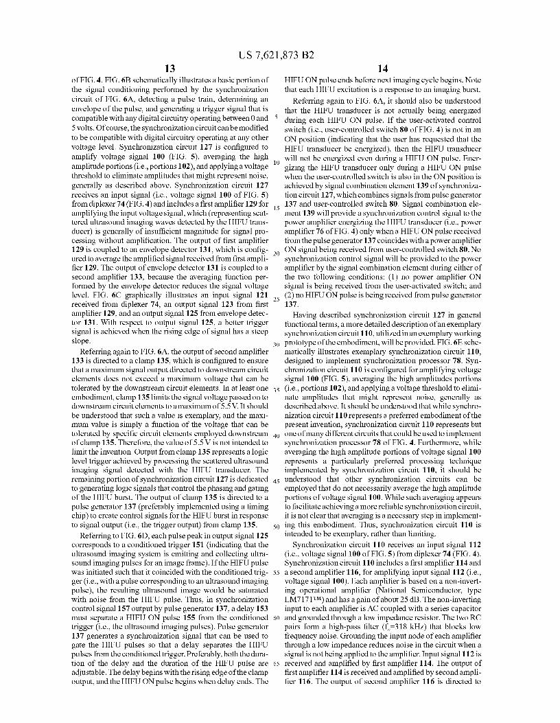
US 7,621,873 B213
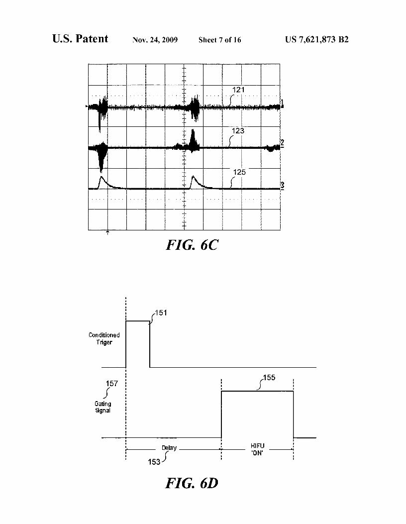
of FIG. 4. FIG. 6B schematically illustrates a basic portion ofthe signal conditioning performed by the synchronizationcircuit of FIG. 6A, detecting a pulse train, determining anenvelope of the pulse, and generating a trigger signal that iscompatible with any digital circuitry operating between 0 and5 volts. Of course, the synchronization circuit can be modifiedto be compatible with digital circuitry operating at any othervoltage level. Synchronization circuit 127 is configured toamplify voltage signal 100 (FIG. 5), averaging the highamplitude portions (i.e., portions 102), and applying a voltagethreshold to eliminate amplitudes that might represent noise,generally as described above. Synchronization circuit 127receives an input signal (i.e., voltage signal 100 of FIG. 5)from diplexer 74 (FIG. 4) and includes a first amplifier 129 foramplifying the input voltage signal, which (representing scat-tered ultrasound imaging waves detected by the HIFU trans-ducer) is generally of insufficient magnitude for signal pro-cessing without amplification. The output of first amplifier129 is coupled to an envelope detector 131, which is config-ured to average the amplified signal received from first ampli-fier 129. The output of envelope detector 131 is coupled to asecond amplifier 133, because the averaging function per-formed by the envelope detector reduces the signal voltagelevel. FIG. 6C graphically illustrates an input signal 121received from diplexer 74, an output signal 123 from firstamplifier 129, and an output signal 125 from envelope detec-tor 131. With respect to output signal 125, a better triggersignal is achieved when the rising edge of signal has a steepslope.
Referring again to FIG. 6A, the output of second amplifier133 is directed to a clamp 135, which is configured to ensurethat a maximum signal output directed to downstream circuitelements does not exceed a maximum voltage that can betolerated by the downstream circuit elements. In at least oneembodiment, clamp 135 limits the signal voltage passed on todownstream circuit elements to a maximum of 5.5 V. It shouldbe understood that such a value is exemplary, and the maxi-mum value is simply a function of the voltage that can betolerated by specific circuit elements employed downstreamof clamp 135. Therefore, the value of 5.5 V is not intended tolimit the invention. Output from clamp 135 represents a logiclevel trigger achieved by processing the scattered ultrasoundimaging signal detected with the HIFU transducer. Theremaining portion of synchronization circuit 127 is dedicatedto generating logic signals that control the phasing and gatingof the HIFU burst. The output of clamp 135 is directed to apulse generator 137 (preferably implemented using a timingchip) to create control signals for the HIFU burst in responseto signal output (i.e., the trigger output) from clamp 135.
Referring to FIG. 6D, each pulse peak in output signal 125corresponds to a conditioned trigger 151 (indicating that theultrasound imaging system is emitting and collecting ultra-sound imaging pulses for an image frame). If the HIFU pulsewas initiated such that it coincided with the conditioned trig-ger (i.e., with a pulse corresponding to an ultrasound imagingpulse), the resulting ultrasound image would be saturatedwith noise from the HIFU pulse. Thus, in synchronizationcontrol signal 157 output by pulse generator 137, a delay 153must separate a HIFU ON pulse 155 from the conditionedtrigger (i.e., the ultrasound imaging pulses). Pulse generator137 generates a synchronization signal that can be used togate the HIFU pulses so that a delay separates the HIFUpulses from the conditioned trigger. Preferably, both the dura-tion of the delay and the duration of the HIFU pulse areadjustable. The delay begins with the rising edge of the clampoutput, and the HIFU ON pulse begins when delay ends. The
14HIFU ON pulse ends before next imaging cycle begins. Notethat each HIFU excitation is a response to an imaging burst.
Referring again to FIG. 6A, it should also be understoodthat the HIFU transducer is not actually being energized
5 during each HIFU ON pulse. If the user-activated controlswitch (i.e., user-controlled switch 80 of FIG. 4) is not in anON position (indicating that the user has requested that theHIFU transducer be energized), then the HIFU transducer
10 will not be energized even during a HIFU ON pulse. Ener-gizing the HIFU transducer only during a HIFU ON pulsewhen the user-controlled switch is also in the ON position isachieved by signal combination element 139 of synchroniza-tion circuit 127, which combines signals from pulse generator
15 137 and user-controlled switch 80. Signal combination ele-ment 139 will provide a synchronization control signal to thepower amplifier energizing the HIFU transducer (i.e., poweramplifier 76 of FIG. 4) only when a HIFU ON pulse receivedfrom the pulse generator 137 coincides with a power amplifier
20 ON signal being received from user-controlled switch 80. Nosynchronization control signal will be provided to the poweramplifier by the signal combination element during either ofthe two following conditions: (1) no power amplifier ONsignal is being received from the user-activated switch; and
25 (2) no HIFU ON pulse is being received from pulse generator137.
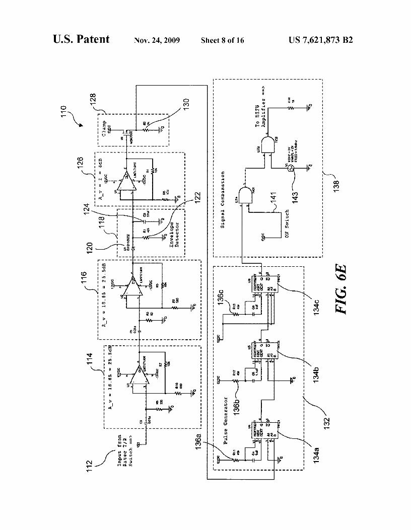
Having described synchronization circuit 127 in generalfunctional terms, a more detailed description of an exemplarysynchronization circuit 110, utilized in an exemplary working
30 prototype of the embodiment, will be provided. FIG. 6E sche-matically illustrates exemplary synchronization circuit 110,designed to implement synchronization processor 78. Syn-chronization circuit 110 is configured for amplifying voltagesignal 100 (FIG. 5), averaging the high amplitudes portions
35 (i.e., portions 102), and applying a voltage threshold to elimi-nate amplitudes that might represent noise, generally asdescribed above. It should be understood that while synchro-nization circuit 110 represents a preferred embodiment of thepresent invention, synchronization circuit 110 represents but
40 one of many different circuits that could be used to implementsynchronization processor 78 of FIG. 4. Furthermore, whileaveraging the high amplitude portions of voltage signal 100represents a particularly preferred processing techniqueimplemented by synchronization circuit 110, it should be
45 understood that other synchronization circuits can beemployed that do not necessarily average the high amplitudeportions of voltage signal 100. While such averaging appearsto facilitate achieving a more reliable synchronization circuit,it is not clear that averaging is a necessary step in implement-
50 ing this embodiment. Thus, synchronization circuit 110 isintended to be exemplary, rather than limiting.
Synchronization circuit 110 receives an input signal 112(i.e., voltage signal 100 of FIG. 5) from diplexer 74 (FIG. 4).Synchronization circuit 110 includes a first amplifier 114 and
55 a second amplifier 116, for amplifying input signal 112 (i.e.,voltage signal 100). Each amplifier is based on a non-invert-ing operational amplifier (National Semiconductor, typeLM7171 TM) and has a gain of about 25 dB. The non-invertinginput to each amplifier is AC coupled with a series capacitor
6o and grounded through a low impedance resistor. The two RCpairs form a high-pass filter (f,-318 kHz) that blocks lowfrequency noise. Grounding the input node of each amplifierthrough a low impedance reduces noise in the circuit when asignal is not being applied to the amplifier. Input signal 112 is
65 received and amplified by first amplifier 114. The output offirst amplifier 114 is received and amplified by second ampli-fier 116. The output of second amplifier 116 is directed to
US 7,621,873 B215
16envelope detector 118. Multiple amplifiers are used to
longer than the sum of the output pulses from the second and
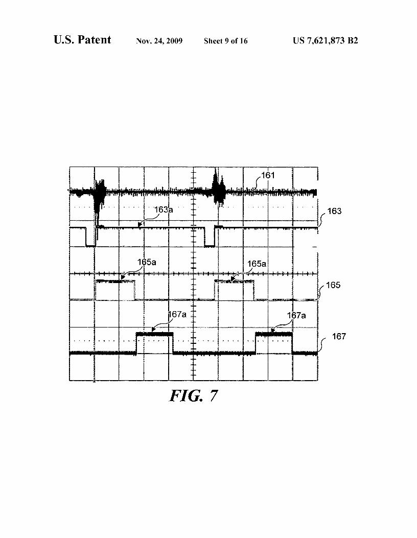
increase the overall gain at higher frequencies. third chips (timing chips 134b and 134c), which occurEnvelope detector 118 is configured to rectify the output of
sequentially, the false trigger will be ignored by the first
second amplifier 116 with a series diode 120 and routes the timing chip. Exemplary signals generated by pulse generatorrectified output to a resistor 122 that is connected to ground in 5 132 are shown in FIG. 7. Signal 161 is an input from T/Rparallel with a capacitor 124. The capacitor is an integrator switch/diplexer 74, signal 163 is the output of timing chipthat stores charge from the amplified pulses that are detected
134a, signal 165 is the output of timing chip 134b, and signal
with the HIFU transducer (i.e., from the output of second
167 is the output of timing chip 134c.amplifier 116). When resistor 122 in envelope detector 118 is
An exemplary method of adjusting the delay and duration
implemented with a potentiometer (Rl in FIG. 6E), the RC io of the HIFU will now be described. It should be recognizedtime constant can be selectively tuned by adjusting the resis- that the exemplary method is not intended to limit the inven-tance such that the output voltage of envelope detector 118
tion, and those of ordinary skill in the art will recognize that
replicates the positive voltage envelope of voltage signal 100
other methods can be used to achieve similar results. In a(FIG. 5) after amplification. This capability enables imple- working prototype, control knobs were incorporated intomentation of the averaging step previously noted, where mul- 15 pulse generator 132 to enable the user to adjust the delaytiple pulses are combined for thresholding. The output of
discussed above. Referring to FIGS. 6E and 7, a first knob was
envelope detector 118 is then coupled to a third amplifier 126. logically coupled with timing chip 134a to control a durationThird amplifier 126, which can be implemented using a of a pulse 163a. As indicated above, so long as pulse 163a is
non-inverting operational amplifier (e.g., a National Semi- longer in duration than the sum of the duration of an outputconductor, type LM7171 TM) with about 6 dB of gain, ampli- 20 pulse 165a (from timing chip 134b) and an output pulse 167afies the output of envelope detector 118. The third amplifier is
(from timing chip 134c), any false trigger will be ignored by
included in synchronization circuit 110 to counteract the volt- the first timing chip. Pulse 163a is initiated by the envelopedage drop across diode 120 in the envelope detector. The out- version of line 161 (i.e., the signal input from T/R switch/put of third amplifier 126 is coupled to a clamp 128. diplexer 74, after it has been processed by the envelope detec-
Clamp 128 is implemented in this embodiment using an 25 tor, amplifier and clamp portions of the synchronization cir-n-channel metal oxide semiconductor field effect transistor cuit). The duration of pulse 163a can be adjusted by the user(MOSFET) (e.g., an ON Semiconductor, type 2N7000 TM), to manipulating the control knob logically coupled with timingthreshold the output from third amplifier 126. Signals above chip 134a, which protects against false triggers from the1.7 V that are received from third amplifier 126 will generate
HIFU itself, since no received signal within this window will
a logic-level output (5 V maximum) across a source resistor 30 trigger the HIFU. Pulse 165a is also triggered by the envel-130 (R2 in FIG. 6E). The clamp also protects circuit elements oped version of line 161. The duration of pulse 165a can bedownstream, which can tolerate a maximum input of 5.5 V. user-adjusted by manipulating a control knob logicallyOutput from clamp 128 represents a logic level trigger coupled with timing chip 134b. The end of pulse 165a trig-achieved by processing the scattered ultrasound imaging sig- gers timing chip 134c to pass the HIFU signal. The HIFU willnal detected with the HIFU transducer. The remaining portion 35 be on (provided the user-controlled switch is actuated) for theof synchronization circuit 110 is dedicated to generating logic
duration of pulse 167a. The duration of pulse 167a can be user
signals for controlling the phasing and gating of the HIFU
adjusted by manipulating a control knob logically coupledburst. with timing chip 134c. While the exemplary implementation
The output of clamp 128 is directed to a pulse generator employed adjustable analog radio-dial style knobs, it should132, implemented using mono-stable multi-vibrator timing 4o be recognized that other user interface implementations arechips 134a, 134b, and 134c (e.g., Texas Instruments, type possible. For example, users could enter values into a soft-SN74121 TM). The timing chips are used to create control
ware program (running on a personal computer, an ASIC, or
signals for the HIFU burst in response to signal output (i.e., microprocessor) that controls the synchronization.the trigger output) from clamp 128. The output from each
Thus, timing chips 134a, 134b, and 134c are triggered
timing chip is a logic-level pulse whose duration is controlled 45 consecutively, which allows pulses 165a and 167a to be gen-by an RC time constant. Potentiometers 136a, 136b, and 136c erated during a non-retriggerable period (i.e.; during eachcan be used in place of fixed resistors, so that the pulse lengths pulse 163a), thereby preventing false triggers. The risingare selectively adjustable. In an initial prototype, only two edge of output signal 125 (see FIG. 6C) triggers timing chiptiming chips (timing chips 134b and 134c) were employed, 134a. The rising edge of pulse 163a (the output from timingincluding one for a phase delay and one to gate the HIFU 50 chip 134a) triggers timing chip 134b. The falling edge ofburst. However, it was determined that because diplexer 74
pulse 165a (the output from timing chip 134b) triggers timing
(shown in FIG. 4) is not a perfect transmit/receive switch, a chip 134c. Finally, timing chip 134c produces pulse 167a.small fraction of the signal from the power amplifier is routed
Referring to the pulses graphically illustrated in FIG. 7, when
to the synchronization circuit (i.e., the initial prototype of
signal 163 transitions from a low amplitude to a high ampli-synchronization circuit 110, which included only two timing 55 tude (i.e.; the initiation of each pulse 163a), pulses 165a andchips in pulse generator 132) during a HIFU burst. Thus, the
167a are generated automatically. Further, the generation of
initial exemplary embodiment prototype with only two tim- pulses 165a and 167a can only be triggered by a low ampli-ing chips processed a small fraction of the signal from the tude to high amplitude transition in signal 163 (i.e.; at thepower amplifier as if it were scattered ultrasound imaging
initiation of each pulse 163a, not at the termination of each
signals detected by the HIFU transducer, and a "false trigger" 60 pulse 163a). FIG. 8 is an ultrasound image 140 that can beresulted. The addition of timing chip 134a upstream of the used to relate the output signal from pulse generator 132 to anoriginal two timing chips (i.e., timing chips 134b and 134c)
ultrasound image. The duration of the phasing pulse deter-
solved the false trigger problem. The timing chips feature mines the location of interference 142 on the ultrasoundinputs that are independent from their outputs through the
image relative to a HIFU focal region 144. Adjusting the
duration of an output pulse. That is, an output pulse cannot be 65 length of the phase delay moves the interference to the left orinitiated until the previous output pulse is complete. Thus, as to the right on the image, and, as shown in FIG. 8, the inter-long as the output pulse of the first chip (timing chip 134a) is
ference can be relegated to the sides of the ultrasound image.
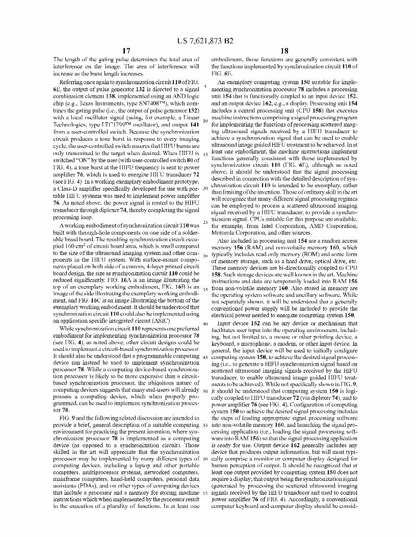
US 7,621,873 B217
The length of the gating pulse determines the total area ofinterference on the image. The area of interference willincrease as the burst length increases.
Referring once again to synchronization circuit 110 of FIG.6E, the output of pulse generator 132 is directed to a signalcombination element 138, implemented using an AND logicchip (e.g., Texas Instruments, type SN740S TM), which com-bines the gating pulse (i.e., the output of pulse generator 132)with a local oscillator signal (using, for example, a LinearTechnologies, type LTC1799 TM oscillator), and output 141from a user-controlled switch. Because the synchronizationcircuit produces a tone burst in response to every imagingcycle, the user-controlled switch ensures that HIFU bursts areonly transmitted to the target when desired. When HIFU isswitched "ON" by the user (with user-controlled switch 80 ofFIG. 4), a tone burst at the HIFU frequency is sent to poweramplifier 76, which is used to energize HIFU transducer 72(see FIG. 4). In a working exemplary embodiment prototype,a Class-D amplifier specifically developed for use with por-table HIFU systems was used to implement power amplifier76. As noted above, the power signal is routed to the HIFUtransducer through diplexer 74, thereby completing the signalprocessing loop.
A working embodiment of synchronization circuit 110 wasbuilt with through-hole components on one side of a solder-able bread board. The resulting synchronization circuit occu-pied 160 cm2 of circuit board area, which is small comparedto the size of the ultrasound imaging system and other com-ponents in the HIFU system. With surface-mount compo-nents placed on both side of a custom, 4-layer printed circuitboard design, the size as synchronization circuit 110 could bereduced significantly. FIG. 16A is an image illustrating thetop of an exemplary working embodiment, FIG. 16B is animage of the side illustrating the exemplary working embodi-ment, and FIG. 16C is an image illustrating the bottom of theexemplary working embodiment. It shouldbeunderstoodthatsynchronization circuit 110 could also be implemented usingan application specific integrated circuit (ASIC).
While synchronization circuit 110 represents one preferredembodiment for implementing synchronization processor 78(see FIG. 4), as noted above, other circuit designs could beused to implement a circuit-based synchronization processor.It should also be understood that a programmable computingdevice can instead be used to implement synchronizationprocessor 78. While a computing device-based synchroniza-tion processor is likely to be more expensive than a circuit-based synchronization processor, the ubiquitous nature ofcomputing devices suggests that many end-users will alreadypossess a computing device, which when properly pro-grammed, can be used to implement synchronization proces-sor 78.
FIG. 9 and the following related discussion are intended toprovide a brief, general description of a suitable computingenvironment for practicing the present invention, where syn-chronization processor 78 is implemented as a computingdevice (as opposed to a synchronization circuit). Thoseskilled in the art will appreciate that the synchronizationprocessor may be implemented by many different types ofcomputing devices, including a laptop and other portablecomputers, multiprocessor systems, networked computers,mainframe computers, hand-held computers, personal dataassistants (PDAs), and on other types of computing devicesthat include a processor and a memory for storing machineinstructions which when implemented by the processor resultin the execution of a plurality of functions. In at least one
18embodiment, those functions are generally consistent withthe functions implemented by synchronization circuit 110 ofFIG. 6E.
An exemplary computing system 150 suitable for imple-5 menting synchronization processor 78 includes a processing
unit 154 that is functionally coupled to an input device 152,and an output device 162, e.g., a display. Processing unit 154includes a central processing unit (CPU 158) that executes
10 machine instructions comprising a signal processing programfor implementing the functions of processing scattered imag-ing ultrasound signals received by a HIFU transducer toachieve a synchronization signal that can be used to enableultrasound image guided HIFU treatment to be achieved. In at
15 least one embodiment, the machine instructions implementfunctions generally consistent with those implemented bysynchronization circuit 110 (FIG. 6E), although as notedabove, it should be understood that the signal processingdescribed in connection with the detailed description of syn-
20 chronization circuit 110 is intended to be exemplary, ratherthan limiting of the invention. Those of ordinary skill in the artwill recognize that many different signal processing regimescan be employed to process a scattered ultrasound imagingsignal received by a HIFU transducer, to provide a synchro-
25 nization signal. CPUs suitable for this purpose are available,for example, from Intel Corporation, AMD Corporation,Motorola Corporation, and other sources.
Also included in processing unit 154 are a random accessmemory 156 (RAM) and non-volatile memory 160, which
30 typically includes read only memory (ROM) and some formof memory storage, such as a hard drive, optical drive, etc.These memory devices are bi-directionally coupled to CPU158. Such storage devices are well known in the art. Machineinstructions and data are temporarily loaded into RAM 156
35 from non-volatile memory 160. Also stored in memory arethe operating system software and ancillary software. Whilenot separately shown, it will be understood that a generallyconventional power supply will be included to provide theelectrical power needed to energize computing system 150.
40 Input device 152 can be any device or mechanism thatfacilitates user input into the operating environment, includ-ing, but not limited to, a mouse or other pointing device, akeyboard, a microphone, a modem, or other input device. Ingeneral, the input device will be used to initially configure
45 computing system 150, to achieve the desired signal process-ing (i.e., to generate a HIFU synchronization signal based onscattered ultrasound imaging signals received by the HIFUtransducer, to enable ultrasound image guided HIFU treat-ments to be achieved). While not specifically shown in FIG. 9,
50 it should be understood that computing system 150 is logi-cally coupled to HIFU transducer 72 (via diplexer 74), and topower amplifier 76 (see FIG. 4). Configuration of computingsystem 150 to achieve the desired signal processing includesthe steps of loading appropriate signal processing software
55 into non-volatile memory 160, and launching the signal pro-cessing application (i.e., loading the signal processing soft-ware into RAM 156) so that the signal processing applicationis ready for use. Output device 162 generally includes anydevice that produces output information, but will most typi-
60 cally comprise a monitor or computer display designed forhuman perception of output. It should be recognized that atleast one output provided by computing system 150 does notrequire a display; that output being the synchronization signal(generated by processing the scattered ultrasound imaging
65 signals received by the HIFU transducer and used to controlpower amplifier 76 of FIG. 4). Accordingly, a conventionalcomputer keyboard and computer display should be consid-

US 7,621,873 B219
20ered as exemplary, rather than as limiting on the scope of thisembodiment of the present invention.
As illustrated in FIG. 10, for testing purposes, a customHIFU transducer housing 170 was built specifically for usewith the HIFU system of FIG. 4. A single element transducerwas used to implement HIFU transducer 72 in the workingprototype of FIG. 10. The single element transducer, disposedin a distal portion 180 of housing 170, is coupled with astepper motor in a center portion 174. The stepper motoradjusts the depth of the HIFU focus within the scatteringtarget. The single element transducer employed in the work-ing prototype of this embodiment has a diameter of about 33mm, a radius of curvature of about 55 mm, and a beam widthof about 1 mm. The distal portion of the housing is filled withdegassed water, although other acoustic coupling materialscan alternatively be used, such as a gel. The housing iscoupled to a boundary layer (such as a skin layer), and thedegassed water filling the distal portion of the housing acous-tically couples the HIFU transducer to the housing. The distalend is enclosed by a thin acoustically-transparent plasticmembrane. In the working prototype, the plastic membranewas affixed to the distal end (implemented using a plasticcone) of custom HIFU transducer housing 170 with anO-ring, thereby securing the degassed water within the hous-ing. Standard sonography gel can be used to couple the plasticmembrane with the boundary layer, although oil, water, orblood could also be used as a coupling medium in clinicalpractice. The degassed water moves within the distal portionof the housing so that when the stepper motor is used tochange the position of the HIFU transducer, sufficient fluid isdisposed between the HIFU transducer and the housing toensure that good acoustic coupling is achieved, without rup-turing the thinplastic membrane. Button 176 in centerportion174 enables the user to actuate the stepper motor, and trigger182 is used to actuate user-controlled switch 80 of FIG. 4, forcontrolling the HIFU burst. The button configuration waslater modified such that a button 182a (see FIG. 11) was usedto actuate the user-controlled switch, so that the handle couldbe removed according to user preferences. Cables that supplypower to the HIFU transducer and control the stepper motorare disposed in a proximal portion 178 of housing 170. Axi-ally translating a single-element transducer to achieve adesired focal depth was chosen as an alternative to a phased-array transducer, to reduce overall complexity. However, itshould be understood that the present invention can be imple-mented using a phased array type HIFU transducer. Phasedarrays require a separate power amplifier for each array ele-ment and control circuitry to adjust focal depth, whichincreases the overall complexity of this system.
A frame 172 was employed to maintain a desired spatialorientation between the HIFU transducer and the ultrasoundimaging probe. The frame incorporates a variety of adjust-ment structures enabling the frame to accommodate a rangeof positions, so that once a desirable spatial orientation isachieved, the adjustment structures (e.g., clamps and screws,although other adjustment structures couldbe used instead, aswill be recognized by those of ordinary skill in the art) can betightened to maintain the desired spatial orientation. Theworking prototype of this exemplary embodiment was usedwith gel tissue phantom 92a as a scattering target. Gel tissuephantoms mimic the acoustic properties of human tissue, andare often used in testing ultrasound equipment. FIG. 11 is aphotograph of housing 170 and a standard pencil 184, toprovide an indication of the relative size of housing 170. Notethat FIGS. 10 and 11 do not show the synchronization circuit,the amplifier, or the ultrasound imaging system.
As indicated in FIG. 4, the HIFU system of this embodi-ment includes the synchronization processor, the poweramplifier, and the HIFU transducer. Such a HIFU system canreadily-be made portable (in the sense that such a HIFU
5 system can be made sufficiently small to be easily transportedby a single person), if a compact, lightweight amplifier isused. The working prototype of this embodiment used aClass-D amplifier measuring 30x23x16 cm and weighing 5kg, but this power amplifier could easily be replaced by a
io smaller and lighter unit. Thus, one aspect of the present inven-tion is directed to a portable HIFU system including a syn-chronization processor configured to process ultrasoundimaging signals received by the HIFU transducer to enablesynchronization between the HIFU transducer and a non-
15 specific ultrasound imaging system.Empirical studies were conducted using the working pro-
totype embodiment of synchronization circuit 110 discussedabove and a HIFU system enclosed in housing 170. Synchro-nized operation was tested by using a charge-coupled device
20 (CCD) camera and two different ultrasound imaging systems,including a SonoSite 1SOTM and an ATL/Phillips HDI1000TM, to monitor the formation of a lesion in gel tissuephantom 92a (see FIG. 10). When HIFU is applied, bovineserum albumin (BSA) in the gel tissue phantom thermally
25 denatures and becomes opaque, which provides an opticalvisualization of lesion formation. Plastic microspheres,approximately 10 µm in diameter, were added to the gel tissuephantom to make the scattering characteristics of the gel morelike those of human tissue.
30 The ultrasound imaging systemwassettoB-mode imagingmodality and to an imaging depth of 4.5 cm, which is approxi-mately the depth of the tissue equivalent gel tissue phantom.The phasing and duration of the HIFU gating signal wereadjusted prior to the experiment such that the interference was
35 relegated to the edges of the ultrasound image. An inductor-capacitor matching circuit transformed the impedance of theHIFU transducer to 50Q at its resonant frequency of 3.1 MHz,which is a load that the Class-D amplifier used in the empiri-cal studies can drive at 100 W of electrical power. The time-
4o averaged electrical power used to drive the transducer duringthe experiment was approximately 40 W, corresponding to a40% duty cycle for the HIFU burst. Images from the CCDcamera and the ultrasound imager were recorded during theexperiment, and then post processed into a single video file.
45 The start of the 60 second HIFU exposure was indicated bythe appearance of interference in the B-mode recording andindicated by an experimenter queue in the CCD recording.Thus, the two videos could be synchronized in time beforethey were combined into one file.
50 Selected frames of the empirical data are shown in FIGS.12A-12C to illustrate the performance of the empirical testsystem. Eachimageis a composite ofbothan optical image ofthe gel tissue phantom (i.e., gel phantom 92a of FIG. 10) andan ultrasound image. CCD-recorded optical images are on the
55 left of each Figure and B-mode ultrasound images are on theright of each Figure. In both the optical images and theB-mode images, the HIFU transducer is on the right and istransmitting to the left, and the imaging probe is on the topand transmitting downwardly. The sequence of the images is
6o as follows. The images in FIG. 12A were collected beforeHIFU began, the images in FIG. 12B were collected after 16seconds of HIFU exposure, and the images in FIG. 12C werecollected after 34 seconds of HIFU exposure. The lesion andthe bright spot are circled in the images of FIG. 12B and FIG.
65 12C. A bright spot is visible in the center of the B-modeimages in FIGS. 12B and 12C. The lesion in the gel tissuephantom is visible as a small, light-colored, cigar-shaped area
US 7,621,873 B221
in the center of the optical images in FIGS. 12B and 12C. Byvisual inspection, the size, shape, and location of the brightspot correlate well with the size, shape, and location of thelesion in the gel tissue phantom. This result agrees with pre-vious studies that compare the bright spot in an ultrasound 5
image (generally corresponding to the focal region of theHIFU burst) with physical lesions. Referring to the B-modeimage portion of FIG. 12B and FIG. 12C (i.e., the images onthe right of each Figure), interference 186 caused by theHIFU burst only appears on the sides (or fringes) of the ioB-mode images. The center portion of each ultrasound imageis unaffected and therefore available for target visualization.Enabling a portion of the ultrasound image (preferably acenter portion, although if desired noise could be shifted tothe center leaving the fringes free of noise) to be free of 15
interference from a HIFU waves during simultaneous ultra-sound imaging and HIFU treatment was the intended result ofthe empirical study. The synchronization technique of thisexemplary embodiment performed as intended.
Additional results were obtained from a similar method, 20
where a HIFU transducer and an imaging probe were bothsubmerged in water and a sponge was used to scatter ultra-sound. HIFU was synchronized with an imager that was oper-ating in B-mode and then using color Doppler. In both cases,the imaging depth was changed while the HIFU was synchro- 25
nized and transmitting. The sequence of ultrasound images inFIGS. 13A-13C and 14A-14C demonstrate the ability ofHIFU systems including a synchronization circuit in accordwith the present invention to adapt in real-time, so as toremain synchronized even when the imaging depth is 30
changed. The ultrasound images of FIGS. I3A-13 C representa sequence of B-mode ultrasound images as the imagingdepth changes. In particular, FIG. 13A is a B-mode ultra-sound image generated using an imaging depth of 4.5 cm,FIG. 13B is a B-mode ultrasound image generated using an 35
imaging depth of 5.5 cm, and FIG. 13C is a B-mode ultra-sound image generated using an imaging depth of 7.0 cm.Note that the total area of interference 188a, 188b, and 188cis different in each ultrasound image. As noted above, thelength of the gating pulse relative to the period of the frame 40
rate determines the total area of interference on the ultrasoundimage. The area of interference will increase as the burstlength increases, or as the frame period decreases (i.e., as therate increases). In this case, increasing the depth of the imagemeans more time is required to generate each frame. Because 45
the HIFU is on for the same amount of time at each depth, atgreater depths, the HIFU interference covers proportionatelyless of the image. The operator is not required to manuallycontrol the duration of the HIFU bursts to ensure that theinterference is limited to the fringes of the ultrasound image, 50
since the synchronization circuit automatically provides thatfunction.
FIG. 14A is a Color Power Doppler ultrasound imagegenerated using an imaging depth of 2.5 cm, FIG. 14B is aColor Power Doppler ultrasound image generated using an 55
imaging depth of 3.5 cm, and FIG. 14C is a Color PowerDoppler ultrasound image generated using an imaging depthof 5.5 cm. Again, note that the total area of interference 189a,189b, and 189c is different in each ultrasound image.
In a particularly preferred embodiment, the HIFU trans- 60
ducer is used as a receiver to detect scattered ultrasoundimaging waves. The scattered ultrasound imaging waves aremanipulated by a synchronization processor to achieve a syn-chronization signal used to synchronize HIFU bursts withultrasound imaging waves, so that acoustic interference pro- 65
duced in ultrasound image is stabilized and confined to theedges of the image. While the use of the HIFU transducer as
22a receiver is considered to be a particularly elegant solution, itshould be understood that a dedicated receiver could insteadbe incorporated into either in ultrasound, imaging probe or aHIFU therapy probe, or a stand-alone dedicated receivercould instead be used, so that the dedicated receiver coulddetect scattered ultrasound imaging waves for processing bythe synchronization circuit.
FIG. 15 is a high-level functional block diagram of anotherembodiment for implementing the present invention, inwhich a dedicated receiver is used to collect the scatteredultrasound imaging signals in place of using the HIFU trans-ducer for that purpose. It should be understood that FIG. 15 isbased on FIG. 4, and includes many of the same elements.Where the same elements in the two circuits serve an identicalpurpose, there is no need to discuss those elements in furtherdetail. Instead, the following description of FIG. 15 will focuson the differences between the block diagrams of FIG. 4(using the HIFU transducer is a receiver to collect scatteredultrasound imaging signals for processing by the synchroni-zation processor) and FIG. 15 (using a dedicated receiver tocollect scattered ultrasound imaging signals forprocessingbythe synchronization processor). FIG. 15 includes dedicatedreceivers 71a, 71b, and 71c. It should be understood thatwhile a plurality of dedicated receivers could be imple-mented, only a single receiver is required. Each receiveremployed is logically coupled to synchronization processor78, and there is no longer any need for diplexer 74. Receiver71a is disposed adjacent to HIFU transducer 72. Such aconfiguration can be achieved by incorporating receiver 71ainto a HIFU therapy probe (such as the HIFU therapy probedefined by housing 170, in FIGS. 10 and 11).
Receiver 71b is a stand-alone receiver (i.e., a receiver thatis not incorporated into either a HIFU therapy probe or inultrasound imaging probe). The position of receiver 71b isselected to ensure that the receiver can receive scattered ultra-sound imaging signals from the ultrasound imaging probe. Insome implementations, it will be desirable to secure receiver71b to frame 172 (see FIG. 10), to maintain a desired spatialorientation between the ultrasound imaging probe, the HIFUtherapy probe, and the receiver. Receiver 71c is disposedadjacent to ultrasound imaging probe 88. Such a configura-tion can be achieved by incorporating receiver 71b into theultrasound imaging probe (which would require a manufac-turer of ultrasound imaging equipment to recognize the needfor such an additional receiver to be incorporated into anultrasound imaging probe, or the modification of an existingultrasound imaging probe), or simply by attaching a separatereceiver to an existing ultrasound imaging probe. Regardlessof how the receiver is implemented (i.e., one of receivers71a-71c, or some combination thereof), the scattered ultra-sound imaging waves collected by the receiver(s) are manipu-lated by the synchronization processor to achieve a synchro-nization signal as described above.
Empirical testing can be performed to determine if a plu-rality of such receivers provide an advantage over a singlereceiver. Such testing can also be used to determine if it wouldbe beneficial to average the signals collected by a plurality ofreceivers, and then provide the averaged signal to the syn-chronization processor for further manipulation. The receiv-ers can be implemented using any conventional receiverdevice that is capable of collecting scattered ultrasound imag-ing waves, as described above. Preferably, any receiver willbe acoustically coupled to the scattering target using anacoustic coupling media, generally as described above,although such a preference is not intended to represent alimitation on the invention.
US 7,621,873 B223
It should be understood that yet another aspect of thepresent invention is directed to a receiver and synchronizationprocessor, which are configured to be used with a HIFUtherapy probe and an ultrasound imaging probe. The receiverand synchronization processor enable the activation of the 5
HIFU therapy probe to be synchronized to the ultrasoundimaging probe, such that at least part of an ultrasound imagegenerated using data collected by the ultrasound imagingprobe does not include interference due to HIFU waves gen-erated by the HIFU therapy probe. The receiver can comprise ioany suitable receiver device that is capable of collecting scat-tered ultrasound imaging waves, as described above. Thesynchronization processor can be implemented using a pro-grammable computing device, an application specific inte-grated circuit (ASIC), or a synchronization circuit, each of 15
which have been discussed above. The receiver can be posi-tioned independently of the ultrasound imaging probe and theHIFU therapy probe, as illustrated in FIG. 15, or the receivercan be incorporated into or coupled with either the ultrasoundimaging probe or the HIFU therapy probe (also as illustrated 20
in FIG. 15). The receiver is logically coupled to the synchro-nization processor. The synchronization processor will belogically coupled to a power amplifier that is used to energizethe HIFU transducer in the HIFU therapy probe. As discussedabove, in a particularly preferred embodiment, the synchro- 25
nization processor is also logically coupled to a user-activatedswitch for selectively controlling the HIFU therapy probe,although such a configuration should not be considered tolimit the invention. Thus, while a particularly preferredembodiment of the present invention comprises a HIFU 30
therapy probe that includes the synchronization processor inthe HIFU therapy probe, it should be understood that otherpreferred embodiments of the present invention are directedto a receiver and synchronization processor for use with exist-ing HIFU therapy probes and ultrasound imaging probes. 35
ADVANTAGES OF THE INVENTION
No modification of a clinical imager is required, and as aresult, the imager company has no added liability when 40used with therapy.
Any imager, any modality, and any user adjustment can beused, while still retaining synchronization between theimaging and therapy ultrasound sources. Thus, the bestimager for the application can be used. 45
There is no added complexity for the user. The synchroni-zation between the imaging and therapy ultrasoundsources is inherent in the system.
The synchronization adapts to user-adjustable controlsassociated with the imaging system (e.g., switching 50imaging modalities, or imaging depth).
The synchronization works with different imaging modali-ties (e.g., Doppler imaging and B-mode imaging).
The expense of the required components are minimal, andin fact, the added receiver electronics provide enhanced 55capability.
While the preferred embodiments discussed above havebeen described in terms of synchronizing therapeutic HIFUwith ultrasound imaging, it should be understood that thepresent invention encompasses synchronizing any type of 60
ultrasound with ultrasound used for imaging, such that ultra-sound imaging can be combined with ultrasound employed,for some other purpose, without the ultrasound used for non-imaging purposes interfering with the ultrasound imaging.For example, ultrasound can be used to provide physical 65
therapy (generally by warming tissue). The levels of ultra-sound used for such physical therapy generally are not suffi-
24ciently energetic to be described as HIFU. The synchroniza-tion techniques and apparatus of the present invention can beused to synchronize ultrasound used to provide physicaltherapy with ultrasound used for imaging. Ultrasound hasalso been investigated for use in conjunction with drug deliv-ery. Again, the synchronization techniques and apparatus ofthe present invention can be used to synchronize ultrasoundused in conjunction with drug delivery with ultrasound usedfor imaging, such that the ultrasound used in conjunction withdrug delivery does not interfere with the ultrasound used forimaging. Some applications of ultrasound involve using ultra-sound to excite micro-bubble based contrast agents, whilesimultaneously using ultrasound imaging to observe the con-trast agent's perfusion into a target region. Again, the syn-chronization techniques of the present invention can be usedto prevent ultrasound used to excite or activate such contrastagents (or other agents) from interfering with ultrasound usedto generate an image. Thus, it should be understood that thesynchronization techniques and apparatus of the presentinvention are not limited to preventing HIFU from interferingwith ultrasound imaging, as the same techniques can be usedto prevent other types of ultrasound from interfering withultrasound used for imaging purposes.
Although the present invention has been described in con-nection with the preferred form of practicing it and modifi-cations thereto, those of ordinary skill in the art will under-stand that many other modifications can be made to thepresent invention within the scope of the claims that follow.Accordingly, it is not intended that the scope of the inventionin any way be limited by the above description, but instead bedetermined entirely by reference to the claims that follow.
The invention in which an exclusive right is claimed isdefined by the following:
1. A method for synchronizing non-imaging ultrasoundwaves and ultrasound imaging waves produced by an ultra-sound imaging system, so at least a portion of an ultrasoundimage produced by the ultrasound imaging system is freefrom interference due to the non-imaging ultrasound waves,comprising the steps of:
(a) producing an output signal in response to receivingscattered ultrasound imaging waves independently ofthe ultrasound imaging system;
(b) manipulating the output signal to generate a synchro-nization signal; and
(c) using the synchronization signal to selectively controlgeneration of the non-imaging ultrasound waves, suchthat at least a portion of the ultrasound image is free frominterference due to the non-imaging ultrasound waves;
wherein the step of producing the output signal comprisesthe step of using a receiver to detect the scattered ultra-sound imaging waves, the receiver being independent ofan ultrasound imaging probe that generates the ultra-sound imaging waves and of a transducer generating thenon-imaging ultrasound waves.
2. The method of claim 1, wherein the non-imaging ultra-sound waves comprise high intensity focused ultrasound(HIFU) waves.
3. The method of claim 1, wherein the step of producing theoutput signal comprises the step of using at least one of areceiver disposed proximate to an ultrasound imaging trans-ducer of the ultrasound imaging system, and a receiver dis-posed proximate to a transducer generating the non-imagingultrasound waves.
4. The method of claim 1, wherein the step of manipulatingthe output signal to generate the synchronization signal com-prises the step of using a computing device to generate thesynchronization signal.
US 7,621,873 B225
5. The method of claim 1, wherein the step of manipulatingthe output signal to generate the synchronization signal com-prises the step of using a synchronization circuit to generatethe synchronization signal.
6. The method of claim 1, wherein the step of manipulatingthe output signal to generate the synchronization signal com-prises the step of automatically generating the synchroniza-tion signal using at least one of a computing device and asynchronization circuit.
7. The method of claim 1, wherein the step of manipulatingthe output signal to generate the synchronization signal com-prises the steps of:
(a) detecting the output signal;(b) determining an envelope of the output signal; and(c) generating a pulse for triggering a transducer that gen-
erates the non-imaging ultrasound waves.8. The method of claim 1, wherein the step of manipulating
the output signal to generate the synchronization signal com-prises the steps of:
(a) amplifying the output signal;(b) averaging a plurality of amplitudes defining the output
signal to generate an averaged output signal;(c) amplifying the averaged output signal;(d) clamping the averaged output signal to insure that the
averaged output signal does not exceed a maximumvalue, thereby generating a clamped signal;
(e)using the clamped signal to generate a pulsed signal fortriggering a transducer that generates the non-imagingultrasound waves; and
(f) combining the pulsed signal for triggering a transducerthat generates the non-imaging ultrasound waves with asignal from a user control switch to generate the syn-chronization signal, such that the synchronization signalis used to selectively control the transducer that gener-ates the non-imaging ultrasound waves only when a userhas activated the user control switch.
9. The method of claim 1, wherein the step of manipulatingthe output signal to generate the synchronization signal com-prises the step of eliminating false triggers.
10. The method of claim 2, wherein the step of producingthe output signal comprises the step of using a HIFU trans-ducer configured to generate the HIFU waves as a receiver todetect the scattered ultrasound imaging waves.
11. The method of claim 7, wherein the step of manipulat-ing the output signal to generate the synchronization signalfurther comprises the step of combining the pulse for trigger-ing the transducer that generates the non-imaging ultrasoundwaves with a signal from a user control switch to generate thesynchronization signal, such that the synchronization signalis used to selectively control the transducer that generates thenon-imaging ultrasound waves only when a user has activatedthe user control switch, regardless of the existence of a pulsethat has been generated based on the output signal.
12. A method for synchronizing non-imaging ultrasoundwaves and ultrasound imaging waves, so that interference inan ultrasound image due to the non-imaging ultrasoundwaves is limited to only a portion of the ultrasound image,comprising the steps of:
(a) using a transducer that generates non-imaging ultra-sound waves to detect scattered ultrasound imagingwaves, the transducer that generates non-imaging ultra-sound waves producing an output signal that is indica-tive of the ultrasound imaging waves that are detected;
(b) manipulating the output signal to generate a synchro-nization signal; and
(c) using the synchronization signal to selectively controlgeneration of the non-imaging ultrasound waves by the
26transducer that generates non-imaging ultrasoundwaves, such that interference in the ultrasound imagegenerated using the ultrasound imaging waves due to thenon-imaging ultrasound waves is limited to only a por-
n tion of the ultrasound image.13. The method of claim 12, wherein the step of manipu-
lating the output signal to generate the synchronization signalcomprises the step of automatically generating the synchro-nization signal using at least one of a computing device and a
10 synchronization circuit.14. The method of claim 12, wherein the step of manipu-
lating the output signal to generate the synchronization signalcomprises the steps of:
(a) amplifying the output signal;15 (b) averaging a plurality of amplitudes defining the output
signal to generate an averaged output signal;(c) amplifying the averaged output signal;(d) clamping the averaged output signal to insure that the
averaged output signal does not exceed a maximum20 value, thereby generating a clamped signal; and
(e) using the clamped signal to generate a pulsed signal fortriggering the transducer that generates the non-imagingultrasound waves.
15. The method of claim 12, wherein the non-imaging25 ultrasound waves comprise at least one of therapeutic ultra-
sound waves and high intensity focused ultrasound waves.16. A method for using ultrasound to simultaneously image
a target area and apply therapeutic ultrasound waves to a
30 treatment site disposed within said target area, comprising thesteps of:
(a) using an ultrasound imaging system to generate anultrasound image of the target area;
(b)without using the ultrasound imaging system, detecting35 the scattered ultrasound imaging waves generated by the
ultrasound imaging system, producing an output signalthat is indicative of the ultrasound imaging waves;
(c) manipulating the output signal to generate a synchro-nization signal; and
40 (d) using the synchronization signal to selectively control atransducer that generates the therapeutic ultrasoundwaves, such that:(i) the synchronization signal ensures that at least a
portion of the ultrasound image is free from interfer-45 ence due to the therapeutic ultrasound waves; and
(ii) a focal point of the therapeutic ultrasound transduceris able to be visualized in the ultrasound image gen-erated by the ultrasound imaging system withoutbeing obscured by interference caused by the thera-
50 peutic ultrasound waves as they induce a therapeuticeffect at the treatment site.
17. The method of claim 16, wherein the step of detectingthe scattered ultrasound imaging waves comprises the step ofusing the therapeutic ultrasound transducer as a receiver to
55 detect the scattered ultrasound imaging waves.18. The method of claim 16, wherein the therapeutic ultra-
sound waves comprise high intensity focused ultrasoundwaves.
19. A system for enabling non-imaging ultrasound to be6o applied to a target area while simultaneously imaging the
target area with an ultrasound imaging system, to enablereal-time ultrasound imaging of the target area to be achievedwhile applying non-imaging ultrasound to the target area,comprising:
65 (a) a receiver configured to detect scattered ultrasoundimaging waves generated by an ultrasound imagingtransducer included within the ultrasound imaging sys-
US 7,621,873 B227
tem, independently of the ultrasound imaging system,producing an output signal that is indicative of the ultra-sound imaging waves; and
(b) a synchronization processor logically coupled to thereceiver, the synchronization processor being config-ured to generate a synchronization signal to be used tocontrol a transducer employed for producing non-imag-ing ultrasound waves, so that at least a portion of anultrasound image generated using the ultrasound imag-ing transducer does not include interference due to thenon-imaging ultrasound waves;
wherein the receiver comprises the transducer that gener-ates the non-imaging ultrasound waves.
20. The system of claim 19, wherein the transducer thatgenerates the non-imaging ultrasound waves comprises atransducer configured to generate high intensity focusedultrasound waves.
21. The system of claim 19, wherein the receiver is config-ured to be coupled with at least one of an ultrasound imagingprobe of the ultrasound imaging system, and a probe thatincludes the transducer that generates the non-imaging ultra-sound waves.
22. The system of claim 19, wherein the synchronizationprocessor is configured to implement the following functions:
(a) detecting the output signal;(b) determining an envelope of the output signal; and(c) generating a pulse for triggering the transducer that
generates the non-imaging ultrasound waves.23. The system of claim 19, further comprising a user
control switch, wherein the synchronization processor is con-figured to implement the following functions:
(a) amplifying the output signal;(b) averaging a plurality of amplitudes defining the output
signal to generate an averaged output signal;(c) amplifying the averaged output signal, to produce an
amplified average output signal;(d) clamping the amplified averaged output signal to insure
that the amplified averaged output signal does notexceed a maximum value, thereby generating a clampedsignal;
(e)using the clamped signal to generate a pulsed signal fortriggering the transducer that generates the non-imagingultrasound waves; and
(f) combining the pulsed signal for triggering the trans-ducer that generates the non-imaging ultrasound waveswith a signal indicative of an active state of the usercontrol switch, to generate the synchronization signal,such that the synchronization signal is used to selec-tively control the transducer that generates the non-im-aging ultrasound waves only when a user has activatedthe user control switch.
24. The system of claim 19, wherein the synchronizationprocessor comprises at least one of a programmable comput-ing device, an application specific integrated circuit, and ahardware-based synchronization circuit.
25. The system of claim 19, wherein the synchronizationprocessor comprises a hardware-based synchronization cir-cuit that includes:
(a)an amplifier for amplifying the output signal, producingan amplified output signal;
(b) an envelope detector for averaging a plurality of ampli-tudes of the amplified output signal, to generate an aver-aged output signal;
(c) an amplifier for amplifying the averaged output signal;
28(d) a clamp for clamping the averaged output signal to
insure that the averaged output signal does not exceed amaximum value, thereby generating a clamped signal;and
5 (e) a pulse generator for using the clamped signal to gen-erate a pulsed signal for triggering the transducer thatgenerates the non-imaging ultrasound waves.
26. A synchronization processor configured to enable non-imaging ultrasound waves to be applied to a target area while
io imaging the target area with an ultrasound imaging system,and to prevent a real-time ultrasound image of the target areafrom being obscured due to interference caused by the non-imaging ultrasound waves, comprising:
(a) an input configured to be coupled to an output signal15 from a receiver that is independent of the ultrasound
imaging system, but which is configured to detect scat-tered ultrasound imaging waves generated by an ultra-sound imaging transducer that is included within theultrasound imaging system, the receiver producing the
20 output signal, which is indicative of the ultrasoundimaging waves; and
(b) an output configured to be coupled to control activationof a non-imaging transducer, so that the non-imagingtransducer is synchronized to produce non-imaging
25 ultrasound waves in regard to production of the ultra-sound imaging waves by the ultrasound imaging trans-ducer, so that at least a portion of an ultrasound imagegenerated using the ultrasound imaging transducer doesnot include interference due to the non-imaging ultra-
30 sound waves produced by the non-imaging transducer;and wherein the synchronization processor is configured
to implement the following functions:(a) amplifying the output signal, producing an amplified
output signal;35 (b) averaging a plurality of amplitudes of the amplified
output signal to generate an averaged output signal;(c) amplifying the averaged output signal to produce an
amplified averaged output signal;(d) clamping the amplified averaged output signal to
40 insure that the amplified averaged output signal doesnot exceed a maximum value, thereby generating aclamped signal; and
(e) using the clamped signal to generate a pulsed signalat the output of the synchronization processor, for
45 triggering the con imaging transducer to producenon-imaging ultrasound waves.
27. The synchronization processor of claim 26, wherein thesynchronization processor comprises at least one of a pro-grammable computing device, an application-specific inte-
50 grated circuit, and a hardware-based synchronization circuit.28. The synchronization processor of claim 26, wherein the
synchronization processor is further configured to implementthe function of combining the pulsed signal for triggering thecon imaging transducer with a signal from a user control
55 switch to generate the synchronization signal, such that thesynchronization signal is used to selectively control the non-imaging transducer only when a user has activated the usercontrol switch.
29. A therapeutic ultrasound system configured for auto-60 matic synchronization with an ultrasound imaging system, to
enable real-time ultrasound imaging of a target area to beachieved while applying therapeutic ultrasound to the targetarea, comprising:
(a) a therapeutic transducer configured to produce thera-65 peutic ultrasound waves;
(b) a receiver configured to detect scattered ultrasoundimaging waves generated by an ultrasound imaging
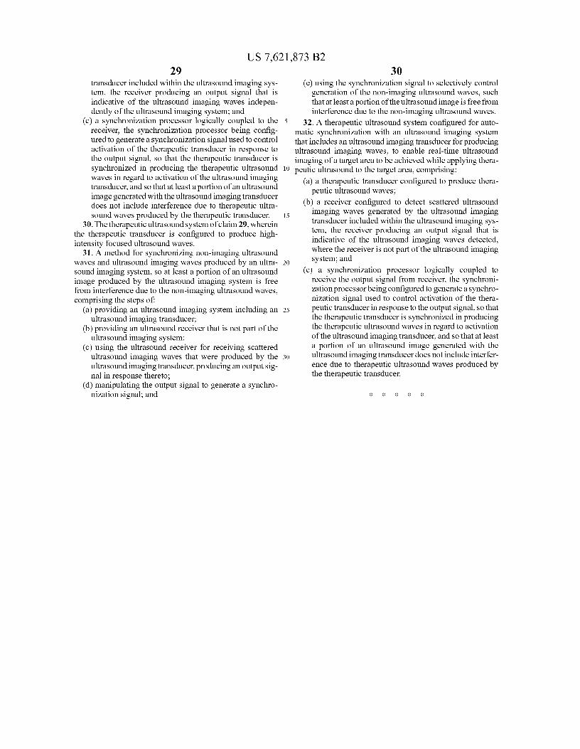
US 7,621,873 B229
transducer included within the ultrasound imaging sys-tem, the receiver producing an output signal that isindicative of the ultrasound imaging waves indepen-dently of the ultrasound imaging system; and
(c) a synchronization processor logically coupled to thereceiver, the synchronization processor being config-ured to generate a synchronization signal used to controlactivation of the therapeutic transducer in response tothe output signal, so that the therapeutic transducer issynchronized in producing the therapeutic ultrasoundwaves in regard to activation of the ultrasound imagingtransducer, and so that at least a portion of an ultrasoundimage generated with the ultrasound imaging transducerdoes not include interference due to therapeutic ultra-sound waves produced by the therapeutic transducer.
30.The therapeutic ultrasound system of claim 29, whereinthe therapeutic transducer is configured to produce high-intensity focused ultrasound waves.
31. A method for synchronizing non-imaging ultrasoundwaves and ultrasound imaging waves produced by an ultra-sound imaging system, so at least a portion of an ultrasoundimage produced by the ultrasound imaging system is freefrom interference due to the non-imaging ultrasound waves,comprising the steps of:
(a) providing an ultrasound imaging system including anultrasound imaging transducer;
(b) providing an ultrasound receiver that is not part of theultrasound imaging system;
(c) using the ultrasound receiver for receiving scatteredultrasound imaging waves that were produced by theultrasound imaging transducer, producing an output sig-nal in response thereto;
(d) manipulating the output signal to generate a synchro-nization signal; and
30(e) using the synchronization signal to selectively control
generation of the non-imaging ultrasound waves, suchthat at least a portion of the ultrasound image is free frominterference due to the non-imaging ultrasound waves.
5 32. A therapeutic ultrasound system configured for auto-matic synchronization with an ultrasound imaging systemthat includes an ultrasound imaging transducer for producingultrasound imaging waves, to enable real-time ultrasoundimaging of a target area to be achieved while applying thera-
10 peutic ultrasound to the target area, comprising:(a) a therapeutic transducer configured to produce thera-
peutic ultrasound waves;(b) a receiver configured to detect scattered ultrasound
15 imaging waves generated by the ultrasound imagingtransducer included within the ultrasound imaging sys-tem, the receiver producing an output signal that isindicative of the ultrasound imaging waves detected,where the receiver is not part of the ultrasound imaging
20 system; and(c) a synchronization processor logically coupled to
receive the output signal from receiver, the synchroni-zation processor being configured to generate a synchro-nization signal used to control activation of the thera-
25 peutic transducer in response to the output signal, so thatthe therapeutic transducer is synchronized in producingthe therapeutic ultrasound waves in regard to activationof the ultrasound imaging transducer, and so that at leasta portion of an ultrasound image generated with the
30 ultrasound imaging transducer does not include interfer-ence due to therapeutic ultrasound waves produced bythe therapeutic transducer.