Embed Size (px)
Citation preview
20
n, 49 9 v,%
mu uuuu ui iiui imi uui uiu mu mu mu lull iuui uu uii mi
(12) United States PatentMuradov et al.
(lo) Patent No.: US 8,147,765 B2(45) Date of Patent: Apr. 3, 2012
(54) APPARATUS FOR HYDROGEN AND CARBON 2,805,177 A 9/1957 KrebsPRODUCTION VIA CARBON 2,926,073 A 2/1960 Robinson et al.
AEROSOL -CATALYZED DISSOCIATION OF 3,284,161 A 11/1966 Pohlenz et al.4,056,602 A 11/1977 Marovich
HYDROCARBONS 5,650,132 A 7/1997 Murata et al.6,395,197 131* 5/2002 Detering et al . .............. 252/373
(75) Inventors: Nazim Z. Muradov, Melbourne, FL 6,670,058 132 12/2003 Muradov(US); Franklyn Smith, Orlando, FL 7,157,167 131* 1/2007 Muradov ...................... 429/411
(US); Ali Tabatabaie-Raissi, 7,622,693 132 * 11/2009 Foret ........................ 219/121.43
Melbourne, FL (US) (Continued)
(73) Assignee: University of Central Florida Research OTHER PUBLICATIONSFoundation, Inc., Orlando, FL (US)
Callahan, Michael "Catalytic Pyrolysis of Methane andOtherHydro-
(*) Notice: Subject to any disclaimer, the term of this carbons" Proc. Conf. Power Sources, vol. 26, (1974) pp. 181-184.
patent is extended or adjusted under 35 (Continued)U.S.C. 154(b) by 751 days.
Primary Examiner Nina Bhat(21) Appl. No.: 12/288,802 (74) Attorney, Agent, or Firm Brian S. Steinberger; Joyce
(22) Filed: Oct. 23, 2008 P. Morlin; Law Offices of Brian S. Steinberger, P.A.
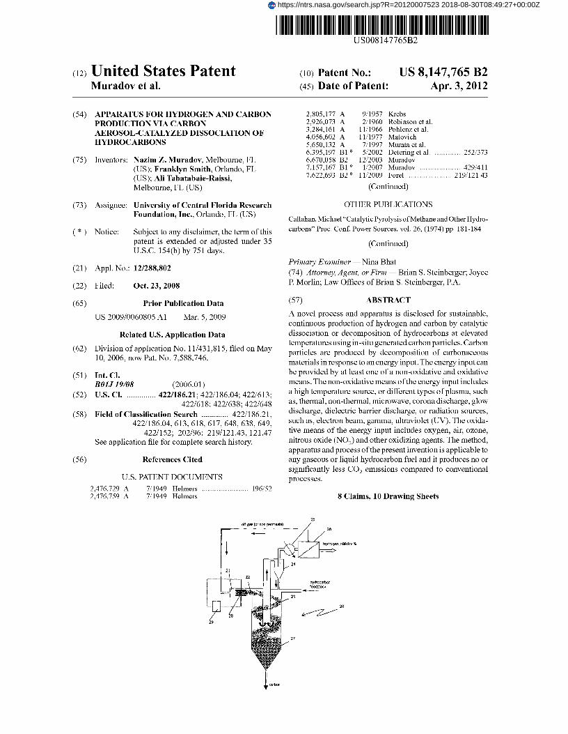
(65) Prior Publication Data (57) ABSTRACT
US 2009/0060805 Al Mar. 5, 2009 A novel process and apparatus is disclosed for sustainable,continuous production of hydrogen and carbon by catalytic
Related U.S. Application Data dissociation or decomposition of hydrocarbons at elevatedtemperatures using in-situ generated carbon particles. Carbon
Division application 11/431,815, filed on May(62)10,
particles are produced by decomposition of carbonaceousnow Pat. No. 588,746.n
7,52006, n7,
materials in response to an energy input. The energy input can
(51) Int. Cl. be provided by at least one of a non-oxidative and oxidative
BOIJ 19108 (2006.01) means. The non-oxidative means of the energy input includes
(52) U.S. Cl . .............. 422/186.21; 422/186.04; 422/613; a high temperature source, or different types of plasma, such
422/618; 422/638; 422/648 as, thermal, non-thermal, microwave, corona discharge, glow
(58) Field of Classification Search ............. 422/186.21, discharge, dielectric barrier discharge, or radiation sources,
422/186.04, 613, 618, 617, 648, 638, 649, such as, electron beam, gamma, ultraviolet (UV). The oxida-
422/152; 202/96; 219/121.43, 121.47 tive means of the energy input includes oxygen, air, ozone,
See application file for complete search history. nitrous oxide (NO2) and other oxidizing agents. The method,apparatus and process of the present invention is applicable to
(56) References Cited any gaseous or liquid hydrocarbon fuel and it produces no orsignificantly less COz emissions compared to conventional
U.S. PATENT DOCUMENTS processes.2,476,729 A 7/1949 Helmers ......................... 196/522,476,759 A 7/1949 Helmers 8 Claims, 10 Drawing Sheets
25
https://ntrs.nasa.gov/search.jsp?R=20120007523 2018-08-30T08:49:27+00:00Z

US 8,147,765 B2Page 2
U.S. PATENT DOCUMENTS
7,931,889 B2* 4/2011 Clark et al . ................... 423/6502007/0111051 Al 5/2007 Muradov
OTHER PUBLICATIONS
Kirk-Othmer, "Carbon (Carbon Black)" Encyclopedia of ChemicalTechnology, Third Edition, vol. 4, (1992) pp. 651-652.Lynum, S. et al., "KV Aerner Based Technologies for Environmen-tally Friendly Energy and Hydrogen Production" Hydrogen EnergyProgress XII, Proceedings of the 12th World Hydrogen Energy Con-ference, Buenos Aires, Argentina, vol. 1, Jun. 21-26, 1998, pp. 637-645.Muradov, Nazim, "Co2-Free Production of Hydrogen by CatalyticPyrolysis of Hydrocarbon Fuel" Energy & Fuels, American Chemi-cal Society, (1998), vol. 12, pp. 41-48.Steinberg, M., "Fossil Fuel Decarbonization Technology for Mitigat-ing Global Warming" International Journal of Hydrogen Energy, vol.24 (1999) pp. 771-777.
Muradov, N., "Catalysis of Methane Decomposition Over ElementalCarbon" Catalysis Communication, vol. 2 (2001) pp. 89-94.Callahan, Michael, "Catalytic Pyrolysis of Methane and OtherHydrocarbons," Proc. Conf. Power Sources, vol. 26, (1974) pp. 181-184.Kirk-Othmer, "Carbon (Carbon Black)," Encyclopedia of ChemicalTechnology, Third Edition, vol. 4, (1992) pp. 651-652.Lynum, S., Hildrum, R., Hox, K., Hugdahl, J., "KV Aerner BasedTechnologies for Environmentally Friendly Energy and HydrogenProduction," Hydogen Energy Progress XII, Proceedings of the 12'World Hydrogen Energy Conference, Buenos Aires, Argentina, vol. 1Jun. 21-25, 1998, pp. 637-645.Muradov, Nazim, "CO2-Free Production of Hydrogen by CatalyticPyrolysis of Hydrocarbon Fuel," Energy & Fuels, American Chemi-cal Society, (1998), vol, 12, pp. 41-48.Muradov, N., "Catalysis of Methane Decomposition Over ElementalCarbon," Catalysis Communication vol. 2, (2001) pp. 89-94.
* cited by examiner

6
2
la
Flig.1
U.S. Patent Apr. 3, 2012 Sheet 1 of 10 US 8,147,765 B2

11
10
15
Fig. 2
U.S. Patent Apr. 3, 2012 Sheet 2 of 10 US 8,147,765 B2

29
n, >99.9 v.%
20
25
U.S. Patent Apr. 3, 2012 Sheet 3 of 10 US 8,147,765 B2
Fig. 3
21A31
20
37
Fig. 4
U.S. Patent Apr. 3, 2012 Sheet 4 of 10 US 8,147,765 B2

35
,^1
20
J7
Fig. 5
21A
U.S. Patent Apr. 3, 2012 Sheet 5 of 10 US 8,147,765 B2

7
U.S. Patent Apr. 3, 2012 Sheet 6 of 10 US 8,147,765 B2
Hvdrnrarhnn
58
20
ex Pyrolysis1G U 4 l4r1
Fig. 6

U.S. Patent
Apr. 3, 2012 Sheet 7 of 10 US 8,147,765 B2
0,45-
0.4-
0,35-
0.3 -to6E: 0.25 -0EE 0.2 -
0.15-
0"1
0.05
0-
0
--*—Carbon (Ni-Cu electrodes)--w— Carbon (Fe electrodes)
* Carbon (SS electrodes)* Carbon (Ni electrodes)
Carbon (Graphite electrodes)Carbon Black (BP2000)
5 10
15
20Time (min.)
Fig. 7

U.S. Patent Apr. 3, 2012 Sheet 8 of 10 US 8,147,765 B2
3.5
NErC 2.5
OE 2
Cr 1.5VEL4
0.5
CB Graphite Ni SS
Fe Ni-Cu
Electrode Type
Fig. 8

U.S. Patent Apr. 3, 2012 Sheet 9 of 10 US 8,147,765 B2
Fig.9

U.S. Patent Apr. 3, 2012 Sheet 10 of 10 US 8,147,765 B2
Fig.1 0
US 8,147,765 B21
APPARATUS FOR HYDROGEN AND CARBONPRODUCTION VIA CARBON
AEROSOL-CATALYZED DISSOCIATION OFHYDROCARBONS
This is a Divisional of U.S. patent application Ser. No.11/431,815 filed May 10, 2006 now U.S. Pat. No. 7,588,746.
STATEMENT REGARDING FEDERALLYSPONSORED RESEARCH
The subject invention was funded in part by NASA GlennResearch Center, grant number NAG3-2751. The govern-ment has certain rights in this invention.
The present invention is related to hydrogen productionmethods, and, in particular, to a process and an apparatus forthe production of hydrogen and carbon via catalytic dissocia-tion of methane and other hydrocarbons.
BACKGROUND AND PRIOR ART
Hydrogen is universally considered a fuel of the future dueto environmental advantages over conventional (i.e., fossil-based) fuels. Another important advantage of using hydrogenstems from the fact that it could be electrochemically (i.e.,without Camot-cycle limitation) converted into electricitywith very high energy conversion efficiency using fuel cells(FC).
To be used in energy conversion devices, hydrogen has tobe produced and stored; however, each of these aspects ofhydrogen technology is associated with major technologicalchallenges.
With regard to production, hydrogen can be produced fromhydrocarbon fuels, such as, methane (CH4), and natural gas(NG), via oxidative reforming or thermal (thennocatalytic)decomposition processes.
Oxidative reforming involves the reaction of hydrocarbonswith oxidants: water, oxygen, or a combination thereof; thecorresponding processes are steam reforming, partial oxida-tion and autothermal reforming, respectively. As a first step,these processes produce a mixture of hydrogen with carbonmonoxide (synthesis-gas), which is followed by water gasshift and CO2 removal stages. The total CO 2 emissions fromthese processes exceed 0.4 m 3 per each m3 of hydrogen pro-duced.
Thermal (thennocatalytic) decomposition or dissociationof hydrocarbons occurs at elevated temperatures (500-1500°C.) in an inert (or oxidant-free) environment and results in theproduction of hydrogen and elemental carbon. Due to the lackof oxidants, no carbon oxides are produced in the process.This eliminates or greatly reduces carbon dioxide (CO2)emissions and obviates the need for water gas shift and CO2removal stages, which significantly simplifies the process.The process produces pure carbon as a valuable byproductthat can be marketed, thus reducing the net cost of hydrogenproduction. The following is a brief description of the prior artwith regard to hydrocarbon thermal (thennocatalytic) decom-position technologies.
Thermal decomposition of natural gas (NG), known as theThermal Black process, has been practiced for decades as ameans of production of carbon black (Kirk-Othmer Encyclo-pedia of Chemical Technology, vol. 4, pages 651-652, Wiley& Sons, 1992). In this process a hydrocarbon stream waspyrolyzed at high temperature (1400° C.) over the preheatedcontact (firebrick) into carbon black particles and hydrogen,which was utilized as a fuel for the process. The process was
2employed in a semi-continuous (i.e., cyclic pyrolysis-regen-eration) mode using two tandem reactors.
U.S. Pat. No. 2,926,073 to Robinson et al. describes theimproved continuous process for making carbon black and
5 byproduct hydrogen by thermal decomposition of natural gas(NG). In this process, NG is thermally decomposed to carbonblack and hydrogen gas is used as a process fuel in a bank ofheated tubes at 982° C.
Thus, both technological approaches described above, tar-io get the production of only one product: carbon black, with
hydrogen being a supplementary fuel for the process.Kvaerner Company of Norway has developed a methane
decomposition process, which produces hydrogen and car-bon black by using high temperature plasma (CB&H process
15 described in the Proceedings of 12th World Hydrogen EnergyConference, Buenos Aires, p. 637-645, 1998). The advan-tages of the plasmochemical process are high thermal effi-ciency (>90%) and simplicity, however, it is an energy inten-sive process.
20 Steinberg et al. proposed a methane decomposition reactorconsisting of a molten metal bath in Int. J. Hydrogen Energy.24, 771-777, 1999. Methane bubbles through molten tin orcopper bath at high temperatures (900° C. and higher). Theadvantages of this system are: an efficient heat transfer to a
25 methane gas stream and ease of carbon separation from theliquid metal surface by density difference.
Much research on methane decomposition over metal andcarbon-based catalysts has been reported in the literature.Transition metals (e.g. Ni, Fe, Co, Pd, and the like.) were
30 found to be very active in methane decomposition reaction;however, there was a catalyst deactivation problem due tocarbon build up on the catalyst surface. In most cases, surfacecarbon deposits were combusted by air (or gasified by steam)to regenerate the catalyst's original activity resulting in large
35 amounts of CO2 byproduct.For example, Callahan describes "a fuel conditioner"
designed to catalytically convert methane and other hydro-carbons to hydrogen for fuel cell applications in Proc. 26thPower Sources Symp. Red Bank, N.7, 181-184, 1974. A
40 stream of gaseous fuel entered one of two reactor beds, wherehydrocarbon decomposition to hydrogen took place at 870-980° C. and carbon was deposited on the Ni-catalyst. Simul-taneously, air entered the second reactor where the catalystregeneration occurred by burning coke off the catalyst sur-
45 face. The streams of fuel and air were reversed for anothercycle of decomposition-regeneration. The reported processdid not require water gas shift and gas separation stages,which was a significant advantage. However, due to cyclicnature of the process, hydrogen was contaminated with car-
5o bon oxides. Furthermore, no carbon byproduct was producedin this process.
U.S. Pat. No. 3,284,161 to Pohlenz et al. describes a pro-cess for continuous production of hydrogen by catalyticdecomposition of NG. Methane decomposition was carried
55 out in a fluidized bed catalytic reactor in the range of tem-peratures from 815° C. to 1093° C. Supported Ni, Fe and Cocatalysts (preferably, Ni/Al203) were used in the process. Thedeactivated (coked) catalyst was continuously removed fromthe reactor to the regenerator where carbon was burned off,
6o and the regenerated catalyst was recycled to the reactor.U.S. Pat. No. 2,476,729 to Helmers et al. describes the
improved method for catalytic cracking of hydrocarbon oils.It was suggested that air is added to the feedstock to partiallycombust the feed such that the heat supplied is uniformly
65 distributed throughout the catalyst bed. This, however, wouldcontaminate and dilute hydrogen with carbon oxides andnitrogen.

US 8,147,765 B23
4Use of carbon catalysts offers the following advantages process for the production of hydrogen and carbon from
over metal catalysts: (i) no need for the regeneration of cata- different hydrocarbons without catalyst regeneration andlysts by burning carbon off the catalyst surface, (ii) no con- with drastically reduced CO z emission when compared totamination of hydrogen by carbon oxides, and (iii) carbon is conventional processes.produced as a valuable byproduct of the process. Muradov 5 The present invention improves upon and overcomes manyhas reported on the feasibility of using different carbon cata- of the deficiencies of the prior art.lysts for methane decomposition reaction in Energy & Fuel,12, 41-48, 1998; Catalysis Communications. 2, 89-94, 2001. SUMMARY OF THE INVENTION
U.S. Pat. No. 2,805,177 to Krebs describes a process forproducing hydrogen and product coke via contacting a heavy 10 A primary objective of the present invention is to develop ahydrocarbon oil admixed with a gaseous hydrocarbon with
sustainable continuous process for hydrogen and carbon pro-
fluidized coke particles in a reaction zone at 927° C.-1371 ° C. duction by catalytic dissociation or decomposition of hydro-Gaseous products containing at least 70 volume % of hydro- carbons with drastically reduced CO 2 emission.gen were separated from the coke, and a portion of coke
A second objective of the present invention is to provide a
particles was burnt to supply heat for the process; the remain- 15 process for the continuous production of hydrogen and car-ing portion of coke was withdrawn as a product. bon via decomposition of hydrocarbon feedstock over carbon
U.S. Pat. No. 4,056,602 to Matovich teaches high tempera- aerosol particles acting as a catalyst for the process.ture thermal decomposition of hydrocarbons in the presence
A third objective of the present invention is to provide a
of carbon particles by utilizing fluid wall reactors. Thermal
process for continuous production of hydrogen and carbondecomposition of methane was conducted at 1260° C.-1871 ° 20 via catalytic decomposition of hydrocarbons over carbonC. utilizing carbon black particles as adsorbents of high flux aerosol particles produced from carbonaceous materialsradiation energy, and initiators of the pyrolytic dissociation of
including, but not limited to, hydrocarbons, carbon monox-
methane. It was reported that 100% conversion of methane
ide, alcohols, esters, carbohydrates, biomass, and the like.could be achieved at 1815° C. at a wide range of flow rates
A fourth objective of the present invention is to provide a
(28.3-141.51/min). 25 process for continuous production of hydrogen and carbonU.S. Pat. No. 5,650,132 to Murata et al. describes the via catalytic decomposition of hydrocarbons over carbon
production of hydrogen from methane and other hydrocar- aerosol particles produced from carbonaceous materials inbons by contacting them with fine particles of carbonaceous response to an energy input such as a high temperature source,materials. The carbonaceous materials included carbon nano- plasma, irradiation, and the like.tubes, activated charcoal, fullerenes C60 -C,o, finely divided 30 A fifth objective of the present invention is to provide adiamond powder as well as soot obtained by thermal decom- process for hydrogen production from any gaseous or liquidposition (or combustion) of different organic compounds or
hydrocarbon including, but not limited to, methane, natural
by arc discharge between carbon electrodes in vacuum. The gas, liquefied petroleum gas, gasoline, diesel fuel, sulfurousoptimal conditions for methane conversion included: prefer- hydrocarbon fuels.able methane concentration: 0.8-5 volume % (balance inert 35 A sixth objective of the present invention is to provide angas), the temperature range of 400° C.-1,200° C. and resi- apparatus for the continuous production of hydrogen anddence times 0.1 -50 sec. carbon via decomposition of hydrocarbon feedstock over in-
U.S. Pat. No. 6,670,058 to Muradov describes the continu- situ generated carbon aerosol particles acting as a catalyst forous process for hydrogen and carbon production using car- the process.bon-based catalysts. The process employs two fluid-solid 40 A seventh objective of the present invention is to provide anvessels: a reactor and a heater/regenerator with carbon par- apparatus that combines, in one continuous process, the oxi-ticles circulating between the vessels in a fluidized state. NG
dative and non-oxidative means of generation of carbon aero-
enters a fluidized bed reactor (FBR) where it is decomposed
sol particles from carbonaceous materials to catalyze aover a fluidized bed of catalytically active carbon particulates single-step, in-situ decomposition of hydrocarbon feedstockat the temperature range of 850° C.-900° C. The resulting 45 to produce hydrogen gas and elemental carbon.hydrogen-rich gas enters a gas separation unit where a stream
A preferred method for producing hydrogen and elemental
of hydrogen with a purity of >99.99 volume % is separated
carbon from hydrocarbon feedstock using a continuous pro-from the unconverted methane, which is recycled to the FBR. cess includes selecting a reactor vessel having a first reactionThe carbon particles are directed to a fluidized bed heater compartment for generating carbon particles connected to awhere they are heated to 1000-1100° C. by hot combustion 50 second reaction compartment that is a catalytic reactor forgases containing steam and CO 2, and simultaneously acti- dissociation of hydrocarbon feedstock into hydrogen gas andvated. The mainportion of carbonparticles is withdrawn from carbon, selecting a carbonaceous material that can be con-the system as a product. verted to carbon particles, transporting the carbonaceous
In summary, the major problem with respect to metal- and
material to the first reaction compartment where the carbon-carbon-catalyzed decomposition of hydrocarbons relates to 55 aceous material is exposedto an energy input that produces angradual deactivation of the catalysts during the process. The outgoing stream of carbon particles, then, directing the out-deactivation could mainly be attributed to the inhibition of the going stream of carbon particles to the second reaction com-catalytic process by the carbon deposits blocking the catalyst partment, then, sending a stream of hydrocarbon feedstock toactive sites. This necessitates the regeneration of the catalysts the second reaction compartment where dissociation of theeither by complete combustion or gasification of the carbon 6o hydrocarbon feedstock occurs over the surface of carbondeposits, in case of metal catalysts or partial gasification of
particles, and collecting hydrogen gas from a first outlet and
carbon deposits, in case of carbon-based catalysts. carbon product from a second outlet of the second reactionThe regeneration step significantly complicates the process compartment.
and results in contamination of hydrogen with carbon oxides, The preferred carbonaceous material is a substance rich innecessitating an elaborate hydrogen purification step and pro- 65 carbon and is readily converted to carbon particles whenduction of considerable amount of CO 2 emission. Thus, there exposed to an energy input that achieves temperatures in ais a need for a more efficient, simple, versatile and sustainable range from approximately 100° C. to approximately 5000°

US 8,147,765 B25
C., temperatures sufficient to convert carbonaceous materialsto carbon particles in the first reaction compartment.
The preferred energy input is provided by at least one of anon-oxidative means, an oxidative means, and mixturesthereof. The preferred non-oxidative means of energy input 5
includes, but is not limited to, at least one of a high tempera-ture source, plasma, and irradiation. The preferred oxidativemeans of energy input is an oxidant selected from at least oneof air, oxygen, ozone and nitrous oxide.
The preferred carbonaceous material is a substance with a ioformula of CPHgX,,, where X is an element including, at leastone of oxygen, nitrogen, sulfur, phosphorus, and p?1, q?0,r?0 The more preferred carbonaceous material includeshydrocarbons and oxygen-, nitrogen-, sulfur- and phospho-rus-containing organic compounds, including, at least one of 15
methane, ethylene, propylene, acetylene, benzene, toluene,acetic acid, propanol, carbon disulfide and mixtures thereof,carbon monoxide (CO), carbohydrates and biomass.
The preferred hydrocarbon feedstock is a hydrocarbonwith the formula C„H_ whereinn?1, and (2n+2)?m?n. The 20
more preferred hydrocarbon feedstock includes methane,natural gas, propane, liquefied petroleum gas (LPG), naphtha,gasoline, kerosene, jet-fuel and diesel fuel.
Another preferred method for producing hydrogen andcarbon from hydrocarbon feedstock using a continuous pro- 25
cess includes selecting a reactor vessel having a first reactioncompartment for generating carbon particles connected to asecond reaction compartment that is a catalytic reactor fordissociation of hydrocarbon feedstock into hydrogen gas andcarbon, selecting a hydrocarbon feedstock that is capable of 30
conversion to carbon particles and capable of dissociationinto hydrogen gas and carbon, dividing the hydrocarbon feed-stock into a first stream and a second stream, transporting thefirst stream of hydrocarbon feedstock to the first reactioncompartment where the hydrocarbon is exposed to an energy 35
input that produces an outgoing stream of carbon particles,directing the outgoing stream of carbon particles to the sec-ond reaction compartment, sending the second stream ofhydrocarbon feedstock to the second reaction compartmentwhere dissociation of the hydrocarbon feedstock occurs over 40
the surface of carbon particles flowing from the first reactioncompartment, and collecting hydrogen gas from a first outletand carbon product from a second outlet of the second reac-tion compartment.
The preferred hydrocarbon feedstock is a compound with 45
the formula C„H_ wherein n?1, and (2n+2)?m?n and ispreferably hydrocarbon feedstock of saturated hydrocarbons,unsaturated hydrocarbons, and aromatic hydrocarbons.
The preferred hydrocarbon feedstock is readily convertedto carbon particles when exposed to an energy input that 50
achieves temperatures in a range from approximately 100° C.to approximately 5000° C. in the first reaction compartment.The preferred energy input is provided by at least one of anon-oxidative means, an oxidative means and a mixturethereof. The non-oxidative means of the energy input 55
includes at least one of a high temperature source, plasma,and irradiation; whereas, the oxidative means of energy inputincludes an oxidant selected from at least one of air, oxygen,ozone and nitrous oxide.
A preferred apparatus for producing hydrogen and carbon 60
from hydrocarbon feedstock using a continuous processincludes a reactor vessel having a first reaction compartmentfor generating carbon particles connected to a second reactioncompartment that is a catalytic reactor for dissociation ofhydrocarbon feedstock into hydrogen gas and carbon, a 65
means for transporting a carbonaceous material that is con-verted to carbon particles to the first reaction compartment
6where the carbonaceous material is exposed to an energyinput that produces an outgoing stream of carbon particles, ameans for directing the outgoing stream of carbon particles tothe second reaction compartment, a means for transporting astream of hydrocarbon feedstock to the second reaction com-partment where dissociation of the hydrocarbon feedstockoccurs over the surface of carbon particles from the firstreaction compartment, and a means for collecting hydrogengas from a first outlet and carbon product from a second outletof the second reaction compartment.
The preferred energy input to the first reaction compart-ment achieves temperatures in a range from approximately100° C. to approximately 5000° C. and is provided by at leastone of a non-oxidative means, an oxidative means, and amixture thereof. The preferred non-oxidative means of theenergy input is at least one of a high temperature source,plasma, and irradiation. The preferred oxidative means of theenergy input is an oxidant selected from at least one of air,oxygen, ozone and nitrous oxide.
Another preferred apparatus for producing hydrogen andcarbon from hydrocarbon feedstock using a continuous pro-cess includes a reactor vessel having a first reaction compart-ment for generating carbon particles connected to a secondreaction compartment that is a catalytic reactor for dissocia-tion of hydrocarbon feedstock into hydrogen gas and carbon,a means for dividing a hydrocarbon feedstock into a firststream that is converted to carbon particles and a secondstream that is dissociated into hydrogen gas and elementalcarbon, a means for transporting the first stream of hydrocar-bon feedstock to the first reaction compartment where thehydrocarbon is exposed to an energy input that produces anoutgoing stream of carbon particles, a means for directing theoutgoing stream of carbon particles to the second reactioncompartment, a means for transporting the second stream ofhydrocarbon feedstock to the second reaction compartmentwhere dissociation of the hydrocarbon feedstock occurs overthe surface of carbon particles from the first reaction com-partment, and a means for collecting hydrogen gas from a firstoutlet and carbon product from a second outlet of the secondreaction compartment.
The preferred energy input achieves temperatures insidethe first reaction compartment in a range from approximately100° C. to approximately 5000° C. and is provided by at leastone of a non-oxidative means, an oxidative means, and amixture thereof. The preferred non-oxidative means of theenergy input is at least one of a high temperature source,plasma, and irradiation and the preferred oxidative means ofthe energy input is an oxidant selected from at least one of air,oxygen, ozone, and nitrous oxide.
Further objects and advantages of the present inventionwill be apparent from the following detailed description of apresently preferred embodiment which is illustrated sche-matically in the accompanying drawings.
BRIEF DESCRIPTION OF THE FIGURES
FIG.1 shows simplified schematics of the general conceptof the present invention.
FIG. 2 shows schematics of the present invention wherecarbonaceous material is a hydrocarbon.
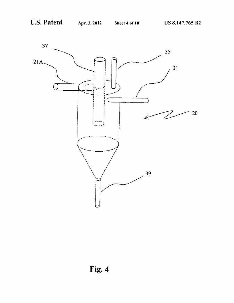
FIG. 3 is a schematic diagram of the process and apparatusfor the production of hydrogen and carbon from a hydrocar-bon feedstock.
FIG. 4 is a perspective view of the reactorFIG. 5 is a plan view of the reactorFIG. 6 shows schematics of the experimental unit for pro-
duction of carbon aerosol particles
US 8,147,765 B27
FIG. 7 is a graph of the kinetics of methane decompositionover carbon aerosol particles produced by non-thermalplasma using different electrode materials
FIG. 8 provides experimental data on methane catalyticdecomposition using carbon aerosol particles produced bynon-thermal plasma.
FIG. 9 is a scanning electron micrograph (SEM) image ofcarbon produced by non-thermal plasma-assisted decompo-sition of methane.
FIG. 10 is a transmission electron micrograph (TEM)image of carbon produced by non-thermal plasma-assisteddecomposition of methane
DESCRIPTION OF THE PREFERREDEMBODIMENTS
Before explaining the disclosed embodiments of thepresent invention in detail it is to be understood that theinvention is not limited in its application to the details of theparticular arrangements shown since the invention is capableof other embodiments. Also, the terminology used herein isfor the purpose of description and not of limitation.
The terms, "carbon" and "elemental carbon" are used inter-changeably herein when referring to the product of the dis-sociation of hydrocarbons.
The terms, "carbon particles" (CP), "carbon aerosol par-ticles" (CAP), and "carbon aerosols" are used interchange-ably herein when referring to the carbon particles produced inthe CAP generator that subsequently function as catalysts inthe catalytic converter portion of the apparatus of the presentinvention.
"Carbonaceous material" as used herein means any sub-stance rich in carbon, which is capable of yielding carbonparticles (CP) or carbon aerosol particles (CAP) with theapplication of energy. The energy input used to convert thecarbonaceous material (CM) to carbon particles that easilycan become airborne, can be applied via non-oxidative andoxidative means.
The non-oxidative means of the energy input implies thatno oxidizing agents are used during production of carbonparticles; this include the use of plasma, irradiation and vari-ous high temperature sources such as a hot filament, a heatingelement, a catalytic burner, and the like, wherein the tempera-tures obtained during the energy input is in a range fromapproximately 100° C. to approximately 5000° C. The irra-diation energy input occurs at lower temperatures, such asapproximately 100° C. and thermal plasma temperatures canbe as high as approximately 5000° C. or even higher.
The oxidative means of the energy input implies that theproduction of carbon particles occurs during high-tempera-ture transformation of carbonaceous (CM) in the presence ofoxidizing agents such as oxygen, air, ozone, hydrogen perox-ide, NO2, and the like, wherein the temperatures obtainedduring the energy input is in a range from approximately 400°C. to approximately 2000° C.
The present invention provides a continuous process for
producing hydrogen and carbon based on a single-step cata-lytic decomposition of hydrocarbons C„H_ over in-situ gen-erated catalytically active carbon aerosol particles (Cae1.)according to the generic equation as follows:
C„Hm+(C_)^C,,+m/2H2 (1)
whereinn?1, and (2n+2)?m?n. C„H_ is hydrocarbon feed-stock including, but is not limited to methane, natural gas,propane, liquefied petroleum gas (LPG), naphtha, gasoline,kerosene, jet-fuel and diesel fuel. Cp,, is carbon product,
8which comprises original CAP and carbon formed duringC„H_ decomposition and laid down on CAP surface.CAP can be produced from a great variety of carbonaceousmaterials (CM) with the general formula of CPHgX,,, where X
5 is an element including, but not limited to oxygen, nitrogen,sulfur, phosphorus, and p?1, q?0, r?0.
Non-limiting examples of carbonaceous materials (CM)include all classes of hydrocarbons (saturated, unsaturated,aromatic), and a variety of oxygen, nitrogen-, sulfur- and
to phosphorus-containing organic compounds, including, butlimited to ethylene, propylene, acetylene, benzene, toluene,acetic acid, propanol, carbon disulfide and mixture thereof,and carbon monoxide (CO).
According to the preferred embodiment of the present15 invention, CAP can be formed from CM upon exposure to an
energy input, as shown in the following generic equations:
C,H,X,+energy input—C,_+products (2)
The energy input to the reaction (2) can be provided by20 non-oxidative and oxidative means. The non-oxidative means
of the energy input includes, but is not limited to a hightemperature source, such as, a hot filament, a heating element,a catalytic burner, and the like, or plasma (thermal, non-thermal, microwave, a corona discharge, a glow discharge, a
25 dielectric barrier discharge), or a radiation source (electronbeam, gamma, X-ray, UV, and the like).
The oxidative means of the energy input includes, but is notlimited to, the use of various oxidizing agents such as oxygen,air, ozone, hydrogen peroxide, NO 21 C102, and the like. In the
30 presence of the oxidants, partial combustion of CM occurs atelevated temperatures, which results in decomposition of CMinto carbon particles and production of combustion productssuch as water and CO 2 and others according to the followinggeneric equation:
35C,H,X,+[Ox]—C,_+H2O+CO2+other products (3)
wherein, [OJ is an oxidant.After the carbonaceous material (CM) is exposed to an
energy input from oxidative or non-oxidative sources in a40 CAP generator with internal temperatures in a range of from
approximately 100° C. to approximately 5000° C., carbonparticles are formed that resemble carbon dust whichbecomes airborne and is directed to a catalytic reactor, tocatalyze the dissociation of hydrocarbon feedstock into
45 hydrogen gas and elemental carbon.A preferred embodiment of the invention is a process for
sustainable, continuous production of hydrogen and elemen-tal carbon via catalytic decomposition of hydrocarbons overin-situ generated carbon aerosol particles comprising the
50 steps of: generating carbon aerosol particles from carbon-aceous materials in response to an energy input in a firstcompartment of a reactor vessel; directing airborne carbonparticles to a second compartment of a reactor vessel forcatalytic decomposition of hydrocarbon feedstock over said
55 carbon aerosol particles at elevated temperatures in the reac-tor; recovering a stream of hydrogen-containing gas (HCG);directing said HCG to a gas separation unit where pure hydro-gen is separated from the stream; recovering carbon productfrom the second compartment of the reactor and collecting it
6o as a final product. An apparatus is also described for carryingout the above-identified process.
Reference is now made to FIG. 1, which illustrates thegeneral concept of the present invention. The stream of car-bonaceous material 5 enters the CAP generator 10 where
65 carbon particles or carbon aerosol particles are producedwhen carbonaceous material (CM) is exposed to an energyinput 15, which can be provided by non-oxidative, or oxida-

US 8,147,765 B29
tive means or a combination thereof. A stream of carbonaerosol particles 11 is introduced into the catalytic reactor 12.The stream of hydrocarbon feedstock 6 enters the catalyticreactor 12 where its dissociation occurs during contact withthe surface of carbon aerosol particles (CAP) thereby produc-ing hydrogen 16 and carbon 18. Hydrogen gas 16 exits thereactor. Solid carbon particles lay down on the surface of CAPand form a final carbonproduct 18, which exits the reactor 12.
FIG. 2 illustrates the invention for the first embodimentwhere carbonaceous material (CM) is hydrocarbon, morespecifically, a hydrocarbon that is a source of carbon aerosolparticles. In this embodiment of the invention, the hydrocar-bon stream 7 is split into two streams 7A and 7B. Smallerstream 7A enters the CAP generator 10, where carbon aerosolparticles are produced upon hydrocarbon exposure to anenergy input 15. A stream of carbon aerosol particles 11 isintroduced into the catalytic reactor 12, where dissociation ofhydrocarbon feedstock from stream 7B occurs during contactwith the surface of carbon aerosol particles (CAP) therebyproducing hydrogen 16 and carbon 18. Hydrogen gas 16 exitsthe reactor. Solid carbon particles lay down on the surface ofCAP and form a final carbon product 18, which exits thereactor 12. It should be apparent to one skilled in the art thatthe concept can be applied not only to hydrocarbons, but toany other carbonaceous material that can produce carbonaerosols upon exposure to an energy input.
The invention is further illustrated by FIG. 3, which pro-vides a simplified schematic diagram of the process for pro-duction of hydrogen and carbon from hydrocarbon feedstock.Carbon aerosol particles are produced in the aerosol produc-tion section 21 of the reactor 20. The stream of carbon aero-sols 22 enters the catalytic section 23 of the reactor 20 wherecarbon-catalyzed decomposition of hydrocarbon feedstockoccurs at 700-1200° C., preferably, 850-1000° C., and pres-sure 1-50 atm, preferably, 2-25 atm.
The vortex configuration of the reactor 20 allows for anadequate mixing and contact time between the carbon aerosolparticles and the hydrocarbon feedstock. The residence timewithin the reaction zone is 0.01-600 seconds (s), preferably,1-60 s. The concentration of hydrogen in the effluent gas fromthe reactor 20 depends on the nature of hydrocarbon feed-stock, temperature, residence time and varies in the range of10-90 volume %, with the balance being mostly methane andhigher hydrocarbons, such as, C2+ 1 including ethylene andother light unsaturated hydrocarbons.
The hydrogen-rich gas exits the reactor 20, through a seriesof cyclones 24 and a heat exchanger 25 and is then directed toa gas separation unit (GSU) 26, where a stream of hydrogenwith the purity of 99.99 volume % is separated from thegaseous stream. The GSU can include a gas separation mem-brane, a pressure swing adsorption (PSA) system, a cryogenicadsorption unit, or any other system capable of separatinghydrogen from hydrocarbons.
Non-permeate gas or PSA off-gas is directed to the aerosolproduction section 21 of the catalytic reactor 20 where it isdecomposed in the presence of a non-thermal plasma with theproduction of hydrogen-rich gas and carbon aerosols 22 thatenter the reaction zone 23. The recycle gas (or PSA off-gas)consists mainly of unconverted hydrocarbons and pyrolysisproducts: olefins and aromatics Alternatively, a portion ofhydrocarbon feedstock could be directed to the aerosol-gen-erator 21 to produce carbon aerosol particles (this option isnot shown in FIG. 3). The non-thermal plasma is produced bymeans of electrodes 28 made of graphite or metals and apower source 29.
One of the important findings of this invention is that thedecomposition of olefins and aromatic hydrocarbons gener-
10ates carbon particles with particularly high catalytic activitytoward hydrocarbon decomposition. In FIG. 3, carbon prod-uct 27 is collected in the bottom section of the vortex reactor20 in the form of carbon particles approximately 100 microns
5 in diameter, and can be continuously withdrawn from thereactor and stored in a carbon collector (not shown in the FIG.3). Due to low thermal energy requirements (i.e., endother-micity) of the hydrocarbon decomposition process and elimi-nation of several gas conditioning and catalyst regeneration
10 stages, the overall CO z emission from the proposed processwould be significantly less than from conventional processes,such as, steam methane reforming.
FIG. 4 is a perspective view of the reactor of the present15 invention showing the inlet tube 21A connected to the aerosol
generating section 21 (shown in FIG. 3), the outlet for hydro-gen gas 37, the inlet 35 for carbon particles collected in thecyclone 24 (shown in FIG. 3), inlet for the hydrocarbon feed-stock 31, and the carbon product outlet 39.
20 FIG. 5 depicts the plan view of the reactor 20 for carbonaerosol-catalyzed decomposition of hydrocarbons. FIG. 5 is aview of the top side showing the inlet for carbon aerosolparticles 21A which is connected to the aerosol generatingsection 21 (shown in FIG. 3), the hydrogen gas outlet 37, the
25 inlet 35 for carbon particles from the cyclone 24 (shown inFIG. 3), carbon product outlet 39, and the hydrocarbon feed-stock inlet 31.
In the second embodiment of the invention an oxidant (e.g.,oxygen or air) is introduced to the carbon aerosol particle
30 (CAP) generating section 21 of the reactor 20 resulting in theproduction of a stream of carbon aerosols via partial combus-tion of the hydrocarbon feedstock or the recycle gas (off-gas).Input of energy in the form of non-thermal plasma or otherenergy source for the production of CAP in this case is not
35 necessary. The rest of the procedure is similar to thatdescribed for the first embodiment. It is apparent to oneskilled in the art that the invention is capable of other embodi-ments, for example, any combination of a non-oxidative andoxidative means of the energy input, such as a combination of
40 non-thermal plasma with oxygen.Thus, the present invention significantly simplifies the
catalytic hydrocarbon decomposition process by eliminatingthe catalyst regeneration step, and, thus, improves its effi-ciency and sustainability. The improvement is achieved by
45 continuous in-situ generation of catalytically active carbonparticles that efficiently decompose hydrocarbon feedstocksinto constituent elements: hydrogen and carbon. This alsoallows the elimination or significant reduction in overall COzemissions from the process.
50
EXAMPLES
Experiments demonstrated technical feasibility of thepresent invention. FIG. 6 depicts the schematics of the carbon
55 aerosol generator 21 consisting of at least two electrodes 52placed inside a tubular or other shape vessel 58. Electrodesare made of graphite or a variety of metals and/or their alloys,such as iron (Fe), nickel (Ni), copper (Cu), stainless steel,nickel-copper (Ni--Cu) alloy, and the like. Apower source 54
60 supplies high voltage to the electrodes resulting in the gen-eration of non-thermal plasma discharge 50.
Hydrocarbon feed 7 enters the CAP generator 21, and isexposed to the non-thermal plasma 50 which can create tem-peratures above 900° C. causing hydrocarbon dissociation
65 and formation of carbon aerosol particles 56 that becomeairborne and are carried away by the gaseous stream or dropvia gravitational pull into the vortex pyrolysis reactor 20.

US 8,147,765 B211
12FIG. 7 is a graph of experimental results of methane ments as may be suggested by the teachings herein are par-
decomposition at 850° C. using carbon aerosol particles as a ticularly reserved especially as they fall within the breadthcatalyst. Carbon aerosol particles were produced by non- and scope of the claims here appended.thermal plasma-assisted decomposition of methane using
We claim:
graphite and metal (Fe, Ni, stainless steel, Ni—Cu) elec- 5 1. An apparatus for producing hydrogen and carbon fromtrodes. The catalytic activity is expressed as a rate of methane
hydrocarbon feedstock using a continuous process consisting
decomposition per unit of weight of carbon. The carbon aero- of:sols produced were compared to that of carbon black BP2000, a) a reactor vessel consisting of two compartments,which is a state-of-the-art carbon catalyst exhibiting highest ai) a first reaction compartment with two inlets and onecatalytic activity within the carbon black family; it has a 10 outlet, a first inlet for an energy source, a second inletsurface area of 1500 m2/g. for a carbonaceous material and an outlet for a stream
It is evident from kinetic curves presented in FIG. 7 that all
of catalytically active aerosol carbon particles gener-samples of carbon aerosol particles produced demonstrated
ated in-situ,
higher initial catalytic activity in methane decomposition aii) a second reaction compartment that is a catalyticcompared to the baseline catalysts BP2000. Carbon aerosols 15 reactor with two inlets and two outlets, a first inlet forproduced in the non-thermal plasma device with Ni Cu
hydrocarbon feedstock, a second inlet for catalyti-
electrodes showed the highest catalytic activity during the cally active aerosol carbon particles, a first outlet fortime interval from approximately 1 minute to approximately
hydrogen gas and a second outlet for elemental car-
13 minutes. The significantly high catalytic activity occurs
bon produced by in-situ dissociation of a hydrocarbonwith no need for regeneration of the catalyst. 20 feedstock into hydrogen gas and carbon, and
FIG. 8 is a bar graph of the experimental results of methane aiii) a connection between the outlet of the first reactiondecomposition at 850° C. using carbon aerosol particles as a compartment and the second inlet of the second reac-catalyst. In this example, carbon aerosol particles were also tion compartment;produced by non-thermal plasma-assisted decomposition of
b) a means for transporting a carbonaceous material to the
methane using graphite and metal (Fe, Ni, stainless steel, 25 second inlet of the first reaction compartment where theNi--Cu) electrodes. The catalytic activity is expressed as a carbonaceous material is exposed to an energy inputrate of methane decomposition per unit of surface area of
provided to the first inlet of the first reaction compart-
carbon. The carbon aerosols produced are compared to that of
ment wherein an outgoing stream of catalytically activecarbon black BP2000 which is shown on the graph as CB. aerosol carbon particles is produced and becomes air-BP2000 is a state-of-the-art carbon catalyst exhibiting high- 30 borne;est catalytic activity within the carbon black family; it has c) a means for directing the outgoing stream of airborne,surface area of 1500 m2/g. catalytically active aerosol carbon particles from the
FIG. 8 shows that carbon aerosols differ in catalytic activ- outlet of the first reaction compartment through the con-ity depending on the material of the electrode used. All
nection to the second inlet of the second reaction com-
samples of carbon aerosols were catalytically more active 35 partment;than carbon black BP2000 despite the fact that their average
d) a means for transporting a stream of hydrocarbon feed-
surface area of approximately 100 m2/g, was one order of
stock to the first inlet of the second reaction compart-magnitude less that that of BP2000. Ni—Cu electrodes show ment where in-situ dissociation of the hydrocarbon feed-a higher level of catalytic activity. stock occurs over the surface of catalytically active
FIG. 9 is a scanning electron microscope (SEM) image of 40 aerosol carbon particles entering the second inlet of thecarbon particles produced from methane exposed to a non- second reaction compartment wherein the aerosol car-thermal plasma source. The SEM image shows that carbon
bon particles act as catalyst for the dissociation of the
particles are in the form of spherical agglomerates with the
hydrocarbon feedstock into hydrogen gas and elementalparticle size dimension of approximately 0.1 µm to approxi- carbon; andmately 0.3 µm. 45 e) a means for collecting hydrogen gas from the first outlet
FIG. 10 is a transmission electron microscope (TEM)
of the second reaction compartment and elemental car-image of carbon particles produced from methane exposed to
bon from the second outlet of the second reaction com-
a non-thermal plasma source. The TEM image shows that partment in a continuous process without catalyst regen-carbon produced is structurally disordered. eration.
For the first time, a process and apparatus combine the 50 2. The apparatus of claim 1, wherein the energy inputgeneration of carbon aerosol particles that are used as cata- directed to the first inlet of the first reaction compartmentlysts in a single-step, catalytic reactor where the in-situ dis- achieves temperatures in a range from approximately 100° C.sociation of hydrocarbon feedstock occurs in the production to approximately 5000° C. and is provided by at least one ofof hydrogen gas and elemental carbon. The combination of
a non-oxidative means, an oxidative means, and a mixture
the two processes, namely, the generation of carbon aerosol 55 thereof.particles and dissociation of hydrocarbon feedstock, in one
3. The apparatus of claim 2, wherein the non-oxidative
apparatus resulted in a significant improvement in existing means of the energy input is at least one of a high temperatureprocesses for the catalytic dissociation of hydrocarbon into source, non-thermal plasma, and irradiation.hydrogen gas and carbon. The need for catalysts regeneration
4. The apparatus of claim 2, wherein the oxidative means of
is eliminated, the process is continuous and sustainable and 60 the energy input is an oxidant selected from at least one of air,the generation of undesirable carbon oxides by-products is oxygen, ozone and nitrous oxide.substantially reduced. 5. An apparatus for producing hydrogen and carbon from a
While the invention has been described, disclosed, illus- hydrocarbon that is a source of carbon aerosol particles usingtrated and shown in various terms of certain embodiments or a continuous process consisting of:modifications which it has presumed in practice, the scope of 65 a) a reactor vessel consisting of two compartments,the invention is not intended to be, nor should it be deemed to ai) a first reaction compartment with two inlets and onebe, limited thereby and such other modifications or embodi- outlet, a first inlet for an energy source, a second inlet

US 8,147,765 B213
for a carbonaceous material and an outlet for catalyti-cally active aerosol carbon particles generated in-situ,
aii) a second reaction compartment that is a catalyticreactor with two inlets and two outlets, a first inlet forhydrocarbon feedstock, a second inlet for catalyti-cally active aerosol carbon particles, a first outlet forhydrogen gas and a second outlet for elemental car-bon produced by in-situ dissociation of a hydrocarbonfeedstock into hydrogen gas and elemental carbon,and
aiii) a connection between the outlet of the first reactioncompartment and the second inlet of the second reac-tion compartment;
b) a means for dividing the hydrocarbon feedstock into afirst stream and a second stream;
c) a means for transporting the first stream of hydrocarbonfeedstock of b) to the second inlet of the first reactioncompartment where the hydrocarbon is exposed to anenergy input directed to the first inlet of the first reactioncompartment wherein an outgoing stream of catalyti-cally active carbon aerosol particles is produced andbecomes airborne;
d) a means for directing the outgoing stream of airbornecatalytically active carbon aerosol particles from theoutlet of the first reaction compartment through the con-nection to the second inlet of the second reaction com-partment;
14e) a means for transporting the second stream of hydrocar-
bon feedstock of b) to the first inlet of the second reac-tion compartment where in situ dissociation of thehydrocarbon feedstock occurs over the surface of cata-
5 lytically active carbon aerosol particles from d) produc-ing hydrogen gas and elemental carbon; and
f) a means for collecting hydrogen gas from the first outletof the second reaction compartment and elemental car-bon from the second outlet of the second reaction com-
bo partment in a continuous process without catalyst regen-eration.
6. The apparatus of claim 5, wherein the energy inputdirected to the first inlet of the first reaction compartmentachieves temperatures in a range from approximately 100° C.
15 to approximately 5000° C. and is provided by at least one ofa non-oxidative means, an oxidative means, and a mixturethereof.
7. The apparatus of claim 6, wherein the non-oxidativemeans of the energy input is at least one of a high temperature
20 source, non-thermal plasma, and irradiation.8. The apparatus of claim 6, wherein the oxidative means of
the energy input is an oxidant selected from at least one of air,oxygen, ozone, and nitrous oxide.
25


![[] Kirk-Othmer Encyclopedia of Chemical Technology(BookZZ.org)-18](https://img.pdfslide.us/doc/110x75/56d6bd641a28ab30168dcd8c/-kirk-othmer-encyclopedia-of-chemical-technologybookzzorg-18.jpg)


![CHLORINATED PARAFFINS [ASSESSMENT]echa.europa.eu/.../orats_summary_2-nitrotoluene_en.pdfMelting point - 9.55 ºC Kirk-Othmer, 1996 Boiling point 221.7 ºC Kirk-Othmer, 1996 Relative](https://img.pdfslide.us/doc/110x75/60e045b44c3f5a4210771b47/chlorinated-paraffins-assessmentecha-melting-point-955-c-kirk-othmer-1996.jpg)