Embed Size (px)
Citation preview

UNITED STATES PATENT AND TRADEMARK OFFICE
______________________
IN THE UNITED STATES PATENT TRIAL AND APPEAL BOARD
______________________
ENDOLOGIX, INC. Petitioner
v.
LIFEPORT SCIENCES LLC Patent Owner
______________________
CASE IPR: 2015-01722
U.S. PATENT NO. 8,192,482 ______________________
PETITION FOR INTER PARTES REVIEW
Mail Stop Patent Board Patent Trial and Appeal Board U.S. Patent and Trademark Office P.O. Box. 1450 Alexandria, VA 22313-1450

Petition for Inter Partes Review of U.S. Patent No. 8,192,482
i
Table of Contents
I. INTRODUCTION ........................................................................................... 1
II. PAYMENT OF FEES (37 C.F.R. §§ 42.15 and 42.103) ................................ 1
III. MANDATORY NOTICES (37 C.F.R. § 42.8) ............................................... 1
A. Real Parties-In-Interest (37 C.F.R. § 42.8(b)(1)) .................................. 1
B. Related Matters (37 C.F.R. § 42.8(b)(2)) .............................................. 1
C. Lead and Backup Counsel (37 C.F.R. § 42.8(b)(3)) ............................. 2
D. Service Information (37 C.F.R. § 42.8(b)(4)) ....................................... 2
IV. GROUNDS FOR STANDING (37 C.F.R. § 42.104(a)) ................................. 3
V. RELIEF REQUESTED ................................................................................... 3
VI. REASONS FOR THE REQUESTED RELIEF .............................................. 3
A. Summary of ‘482 Petition ..................................................................... 3
B. Overview of the Prior Art Specifically Cited Below ............................ 4
1. U.S. Patent No. 8,317,854 (“Ryan”) ........................................... 4
2. U.S. Patent No. 5,405,377 (“Cragg”) ......................................... 4
3. U.S. Patent No. 5,064,435 (“Porter”) ......................................... 4
4. U.S. Patent No. 4,994,071 (“MacGregor”) ................................. 4
5. U.S. Patent No. 5,135,536 (“Hillstead”) ..................................... 5
6. U.S. Patent No. 4,733,665 (“Palmaz”) ....................................... 5
7. U.S. Patent No. 5,370,683 (“Fontaine”) ..................................... 5
8. U.S. Patent No. 5,707,386 (“Schnepp-Pesch”) ........................... 5
9. U.S. Patent No. 5,421,955 (“Lau”) ............................................. 6
10. U.S. Patent No. 5,234,457 (“Andersen”) .................................... 6

Petition for Inter Partes Review of U.S. Patent No. 8,192,482
ii
C. Background of the Technology and Summary of ‘482 Patent .............. 6
1. Well Known Prior Art Prosthesis Designs ................................. 7
2. The Patent Owner Only Overcame Previous Rejections By Arguing That The Disclosed Non-Helical Design Was Novel ......................................................................................... 11
3. Elements from Helical and Non-Helical Stents Were Known To be Interchangeable .................................................. 12
4. Well Known, Interchangeable Prior Art Securing Means ........ 13
D. Summary of the Prosecution of the ‘482 Patent ................................. 16
E. The ‘482 Patent Cannot Claim Priority to EP 94400284 or EP 94401306 ............................................................................................. 16
F. Related ‘167 Patent IPR and Institution Decision .............................. 18
VII. PERSON OF ORDINARY SKILL IN THE ART ........................................ 18
VIII. CLAIM CONSTRUCTION .......................................................................... 19
A. Additional Terms for Construction ..................................................... 20
1. “segment” (Claims 2-5,8-9, and 12) ......................................... 20
IX. STATEMENT OF THE PRECISE RELIEF REQUESTED AND THE REASONS THEREFORE (37 C.F.R. § 42.22(a) AND 42.104(b)) .............. 21
A. Ground 1: Claims 1-9, 12-13, 21-22, and 30 Are Anticipated by Ryan ..................................................................................................... 21
B. Ground 2: Claims 1-9, 12-13, 21-22, and 30 Are Obvious Over Ryan ..................................................................................................... 37
C. Ground 3: Claims 1-9, 12-13, 21-22, and 30 Are Obvious Over Ryan In View Of Cragg ...................................................................... 38
D. Ground 4: Claim 2-4, 6-7, and 12 Are Obvious Over Ryan In View Of Porter .................................................................................... 40

Petition for Inter Partes Review of U.S. Patent No. 8,192,482
iii
E. Ground 5: Claims 2, 5, 7-9 Are Obvious Over Ryan In View Of MacGregor ........................................................................................... 43
F. Ground 6: Claims 1-3, 5-6, 12-13, 21, and 30 Are Anticipated by Hillstead ............................................................................................... 45
G. Ground 7: Claims 1-3, 5-6, 12-13, 21 and 30 Are Obvious Over Hillstead In View Of Palmaz .............................................................. 55
H. Ground 8: Claims 1-9, 12-13, 21-22, and 30 Are Obvious Over Hillstead In View Of Palmaz and Ryan .............................................. 57
X. CONCLUSION .............................................................................................. 60

Petition for Inter Partes Review of U.S. Patent No. 8,192,482
iv
List of Exhibits
Ex. 1001 U.S. Patent No. 8,192,482 (“‘482 Patent”)
Ex. 1002 Declaration of Richard A. Hillstead, Ph.D
Ex. 1003 Curriculum Vitae of Richard A. Hillstead, Ph.D
Ex. 1004 U.S. Patent No. 8,317,854 (“Ryan”)
Ex. 1005 U.S. Patent No. 5,405,377 (“Cragg”)
Ex. 1006 U.S. Patent No. 5,064,435 (“Porter”)
Ex. 1007 U.S. Patent No. 4,994,071 (“MacGregor”)
Ex. 1008 U.S. Patent No. 5,135,536 (“Hillstead”)
Ex. 1009 U.S. Patent No. 4,733,665 (“Palmaz”)
Ex. 1010 U.S. Patent No. 5,370,683 (“Fontaine”)
Ex. 1011 U.S. Patent No. 5,707,386 (“Schnepp-Pesch”)
Ex. 1012 U.S. Patent No. 5,421,955 (“Lau”)
Ex. 1013 U.S. Patent No. 5,234,457 (“Andersen”)
Ex. 1014 Prosecution History of U.S. Patent No. 8,192,482
Ex. 1015 Amended Complaint in Case No. 1:12-cv-01791-GMS, filed on
August 12, 2014
Ex. 1016 Excerpts from the Deposition of Dr. George Goicoechea on July 8,
2015
Ex. 1017 Board of Patent Appeals and Interferences Decision in Interference

Petition for Inter Partes Review of U.S. Patent No. 8,192,482
v
No. 104,192 (April 7, 2000)
Ex. 1018 Memorandum Opinion, Case No. 1:01-cv-2015 (D.D.C. March 31,
2006)
Ex. 1019 Federal Circuit decision in Boston Scientific Scimed, Inc. v. Medtronic
Vascular, Inc., 497 F.3d 1293 (Fed. Cir. 2007)
Ex. 1020 U.S. Patent No. 6,117,167
Ex. 1021 IPR2014-01319, Paper No. 7, Institution Decision (PTAB Feb. 23,
2015)
Ex. 1022 Excerpts from LifePort LLC’s Disclosure of Initial Claim Charts,
dated September 10, 2014

Petition for Inter Partes Review of U.S. Patent No. 8,192,482
1
I. INTRODUCTION
Endologix, Inc. (“Petitioner” or “Endologix”) hereby petitions for inter
partes review of claims 1-9, 12-13, 21-22, and 30 of U.S. Patent No. 8,192,482
(“‘482 Patent”) (Ex. 1001) under 35 U.S.C. §§ 311–319 and 37 C.F.R. § 42.
II. PAYMENT OF FEES (37 C.F.R. §§ 42.15 and 42.103)
Petitioner authorizes the USPTO to charge the required fees for inter partes
review of 14 claims, and any additional fees, to Deposit Account No. 02–1818.
III. MANDATORY NOTICES (37 C.F.R. § 42.8)
A. Real Parties-In-Interest (37 C.F.R. § 42.8(b)(1))
Endologix, located at 2 Musick, Irvine, California 92618, is the real party-in-
interest.
B. Related Matters (37 C.F.R. § 42.8(b)(2))
The ‘482 Patent is the subject of an infringement lawsuit brought by
LifePort Sciences LLC (“LifePort” or “PO”) against Petitioner in the United States
District Court for the District of Delaware, Case No. 1:12-cv-01791-GMS
(“District Court Case”). The ‘482 Patent was asserted against Endologix on
August 12, 2014, in the Amended Complaint (Dkt. 34) served via the CM/ECF
system after the Court granted LifePort’s Motion to Amend Complaint (Dkt. 33).
See Ex. 1015.
Petition for Inter Partes Review of U.S. Patent No. 8,192,482
2
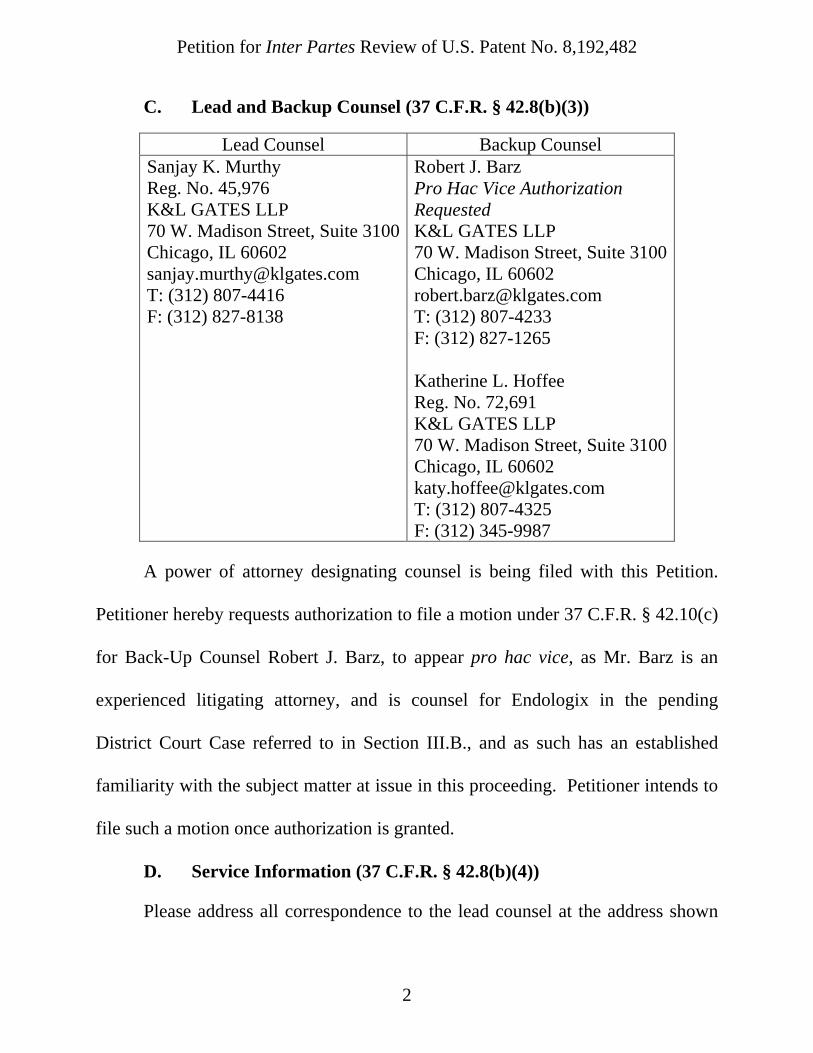
C. Lead and Backup Counsel (37 C.F.R. § 42.8(b)(3))
Lead Counsel Backup Counsel Sanjay K. Murthy Reg. No. 45,976 K&L GATES LLP 70 W. Madison Street, Suite 3100Chicago, IL 60602 [email protected] T: (312) 807-4416 F: (312) 827-8138
Robert J. Barz Pro Hac Vice Authorization Requested K&L GATES LLP 70 W. Madison Street, Suite 3100Chicago, IL 60602 [email protected] T: (312) 807-4233 F: (312) 827-1265 Katherine L. Hoffee Reg. No. 72,691 K&L GATES LLP 70 W. Madison Street, Suite 3100Chicago, IL 60602 [email protected] T: (312) 807-4325 F: (312) 345-9987
A power of attorney designating counsel is being filed with this Petition.
Petitioner hereby requests authorization to file a motion under 37 C.F.R. § 42.10(c)
for Back-Up Counsel Robert J. Barz, to appear pro hac vice, as Mr. Barz is an
experienced litigating attorney, and is counsel for Endologix in the pending
District Court Case referred to in Section III.B., and as such has an established
familiarity with the subject matter at issue in this proceeding. Petitioner intends to
file such a motion once authorization is granted.
D. Service Information (37 C.F.R. § 42.8(b)(4))
Please address all correspondence to the lead counsel at the address shown

Petition for Inter Partes Review of U.S. Patent No. 8,192,482
3
above. Petitioner also consents to electronic service by email.
IV. GROUNDS FOR STANDING (37 C.F.R. § 42.104(a))
Petitioner certifies that (1) the ‘482 Patent, issued on June 5, 2012, is
available for inter partes review; (2) under 35 U.S.C. § 315(b), Petitioner is not
barred or estopped from requesting inter partes review of the ‘482 Patent on the
grounds identified herein (see Amneal Pharm., LLC v. Endor Pharm. Inc.,
IPR2014-00360, Paper 15 at 7-10 (PTAB June 27, 2014)); and (3) Petitioner has
not filed a complaint relating to the ‘482 Patent. This Petition is filed in
accordance with 37 C.F.R. § 42.106(a).
V. RELIEF REQUESTED
Petitioner asks that the Board review the accompanying prior art and
analysis, institute a trial for Inter Partes Review of claims 1-9, 12-13, 21-22, and
30 of the ‘482 Patent, and cancel those claims as invalid under 35 U.S.C. § 102 or
35 U.S.C. § 103.
VI. REASONS FOR THE REQUESTED RELIEF
A. Summary of ‘482 Petition
Claims 1-9, 12-13, 21-22, and 30 of the ‘482 Patent are anticipated by the
prior art, or at best, cover nothing more than obvious combinations of well known
endoluminal prosthesis designs and/or very well known features of such
endoluminal prostheses. Indeed, the first named inventor testified that the claimed
features added to obtain allowance were merely a matter of “design choice” that

Petition for Inter Partes Review of U.S. Patent No. 8,192,482
4
required nothing more than “routine engineering.” Ex. 1016 (Goicoechea Dep.) at
144:6-20; see also id. at 139:14-25.
B. Overview of the Prior Art Specifically Cited Below
1. U.S. Patent No. 8,317,854 (“Ryan”)
U.S. Patent No. 8,317,854 (“Ryan”) (Ex. 1004) was filed on July 19, 1996,
claims priority to June 19, 1994, and issued on November 27, 2012. Ryan is prior
art under 35 U.S.C. § 102(e). Ryan discloses a bifurcated stent with a graft used
for treating aneurysms.
2. U.S. Patent No. 5,405,377 (“Cragg”)
U.S. Patent No. 5,405,377 (“Cragg”) (Ex. 1005) was filed on February 21,
1992, and issued on April 11, 1995. Cragg is prior art under 35 U.S.C. § 102(e).
Cragg discloses an intraluminal stent that includes hoops that are connected by
adjacent apices. The stent is compressible and self-expanding.
3. U.S. Patent No. 5,064,435 (“Porter”)
U.S. Patent No. 5,064,435 (“Porter”) (Ex. 1006) was filed on June 28, 1990,
and issued on November 12, 1991. Porter is prior art under 35 U.S.C. § 102(b).
Porter discloses a non-helical stent.
4. U.S. Patent No. 4,994,071 (“MacGregor”)
U.S. Patent No. 4,994,071 (“MacGregor”) (Ex. 1007) was filed on May 22,
1989, and issued on February 19, 1991. MacGregor is prior art under 35 U.S.C. §
102(b). MacGregor discloses an expandable bifurcated stent that is made of a

Petition for Inter Partes Review of U.S. Patent No. 8,192,482
5
series of interconnected wire loops.
5. U.S. Patent No. 5,135,536 (“Hillstead”)
U.S. Patent No. 5,135,536 (“Hillstead”) (Ex. 1008) was filed on February 5,
1991, and issued on August 4, 1992. Hillstead is prior art under 35 U.S.C. §
102(b). Hillstead discloses a non-helical stent.
6. U.S. Patent No. 4,733,665 (“Palmaz”)
U.S. Patent No. 4,733,665 (“Palmaz”) (Ex. 1009) was filed on November 7,
1985, and issued on March 29, 1988. Palmaz is prior art under 35 U.S.C. § 102(b).
Palmaz discloses expandable intraluminal vascular graft that is non-helical in
shape and can be expanded using a balloon.
7. U.S. Patent No. 5,370,683 (“Fontaine”)
U.S. Patent No. 5,370,683 (“Fontaine”) (Ex. 1010) was filed on February 4,
1994, claims priority to March 25, 1992, and issued on December 6, 1994.
Fontaine is prior art under 35 U.S.C. § 102(e). Fontaine discloses a vascular stent
for reducing hemodynamic disturbances caused by angioplasty.
8. U.S. Patent No. 5,707,386 (“Schnepp-Pesch”)
U.S. Patent No. 5,707,386 (“Schnepp-Pesch”) (Ex. 1011) was a PCT
application filed on January 22, 1994, claims priority to February 4, 1993, and
issued on January 13, 1998. Schnepp-Pesch is prior art under 35 U.S.C. § 102(e).
Schnepp-Pesch discloses a stent that has high flexibility because of successively
arranged hoops in the axial direction which extend over its circumference.

Petition for Inter Partes Review of U.S. Patent No. 8,192,482
6
9. U.S. Patent No. 5,421,955 (“Lau”)
U.S. Patent No. 5,421,955 (“Lau”) (Ex. 1012) was filed on March 17, 1994,
claims priority to October 28, 1991, and issued on June 6, 1995. Lau is prior art
under 35 U.S.C. § 102(e). Lau discloses an expandable stent for implantation in
the body and a method for making such a stent from a single length of wire.
10. U.S. Patent No. 5,234,457 (“Andersen”)
U.S. Patent No. 5,234,457 (“Andersen”) (Ex. 1013) was filed on October 9,
1991, and issued on August 10, 1993. Andersen is prior art under 35 U.S.C. §
102(b). Andersen discloses a stent assembly, delivery system and method of
manufacture therefor.
C. Background of the Technology and Summary of ‘482 Patent
The ‘482 Patent describes an endoluminal prosthesis for use in a blood
vessel. ‘482 Patent, 1:14-15; Declaration of Richard A. Hillstead, Ph.D, Ex. 1002,
¶ 22 (hereinafter, “Hillstead Decl.”). For decades before the ‘482 Patent, doctors
had used stents, grafts and prostheses for the treatment of angeological diseases.
Id. A prosthesis is a stent (the wire portion) with a graft (the fabric portion)
covering it. Id. at ¶ 23. A prosthesis is used to provide a prosthetic intraluminal
wall because it allows the blood flow to flow within it. ‘482 Patent, 1:23-25;
Hillstead Decl. ¶ 23. A prosthesis is used to treat an aneurysm by removing the
pressure on a weakened part of an artery, thus reducing the risk of embolism, or of
the natural artery wall bursting. ‘482 Patent, 1:27-29; Hillstead Decl. ¶ 24.
Petition for Inter Partes Review of U.S. Patent No. 8,192,482
7
1. Well Known Prior Art Prosthesis Designs
Stents, grafts and prostheses date back to 1980’s. See, e.g., Palmaz;
Hillstead Decl. ¶ 25. By the time of the effective filing date of the ‘482 Patent, a
wide variety of stent designs were well known in the art. The well known stents
were typically tubular and could include extensions, bifurcations, and extensions
for the bifurcations. Hillstead Decl. ¶ 25. The well known tubular structures were
made out of a filament (typically wire) that could take on a variety of patterns to
provide various advantages such as strength, stability, and flexibility. Id.
One way to categorize the well known patterns was to classify a design as
helical or non-helical. Id. at ¶ 26. Both helical and non-helical patterns often took
on a well known zig-zag pattern whereby the wire forming the stent looped around
an axis in a repeating zig-zag pattern to form a cylinder. Id. The ‘482 Patent
explicitly recognized the existence of this well known prior art pattern. ‘482 Patent
at 1:40-59; Hillstead Decl. ¶ 27. The ‘482 Patent also recognized that this prior art
zig-zagging pattern was commonly utilized in prior art helical (e.g., EP-A-
0556850) and non-helical (U.S. Patent No. 4,733,655) stents. Id.
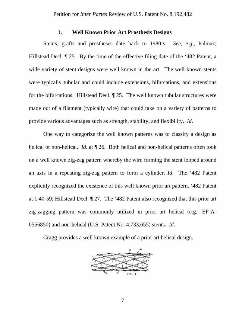
Cragg provides a well known example of a prior art helical design.

Petition for Inter Partes Review of U.S. Patent No. 8,192,482
8
Cragg at Fig. 1; Hillstead Decl. ¶ 28. The zig-zaging pattern in Cragg gradually
works its way down the length of the cylinder in helical fashion. Id. The apices of
the zigs and zags are not aligned perpendicular to the longitudinal axis of the stent.
Fontaine also discloses a helical pattern. Id. at ¶ 29. To illustrate, Figure 7 of
Fontaine depicts a partially unwound helical pattern:
Fontaine at Fig. 7; Hillstead Decl. ¶ 29.
Non-helical patterns were also very well known at the time. Hillstead Decl.
¶ 30. For example, Hillstead, Palmaz, Ryan, and Schnepp-Pesch all disclose stents
that include non-helical zig-zaging patterns that make a series of loops around the
longitudinal axis, where each loop is in a plane perpendicular to the axis:
longitudinal axis
Zig-zags are not perpendicular to the longitudinal axis; they wind to form a helix around the axis
Helical Stent

Petition for Inter Partes Review of U.S. Patent No. 8,192,482
9
Well Known Prior Art Non-Helical Stent Designs
longitudinal axis longitudinal axis
Ryan
Hillstead
Palmaz
Schnepp-Pesch
longitudinal axis
longitudinal axis
Zig-zags/Hoops are perpendicular to the longitudinal axis; they do not form a helix around the axis

Petition for Inter Partes Review of U.S. Patent No. 8,192,482
10
Hillstead at Fig. 2; Palmaz at Fig. 1A; Schnepp-Pesch at Fig.2; Ryan at Fig. 2;
Hillstead Decl. ¶ 30. The ‘482 Patent attempts to claim this well known non-
helical stent design. The background of the specification of the ‘482 Patent
acknowledges both helical and non-helical designs, but the summary of the
invention only focuses on differentiating the alleged invention of the ‘482 Patent
from the well known helical designs without giving credence to the cited non-
helical designs (e.g., Palmaz). Compare ‘482 Patent at 1:48-59 with ‘482 Patent at
3:62-4:7; see also Hillstead Decl. ¶ 31. Specifically, it states: “the wire may be of
an entirely novel configuration, namely one in which the wire forms a plurality of
hoops such that the plane of the circumference of each hoop is substantially
perpendicular to the longitudinal axis of the stent.” ‘482 Patent at 3:63-67.
longitudinal axis
Like the four prior art examples above, the zig-zags/hoops of the ‘482 Patent are
perpendicular to the longitudinal axis; they do not form a helix around the axis
‘482 Patent Non-Helical Stent
Petition for Inter Partes Review of U.S. Patent No. 8,192,482
11
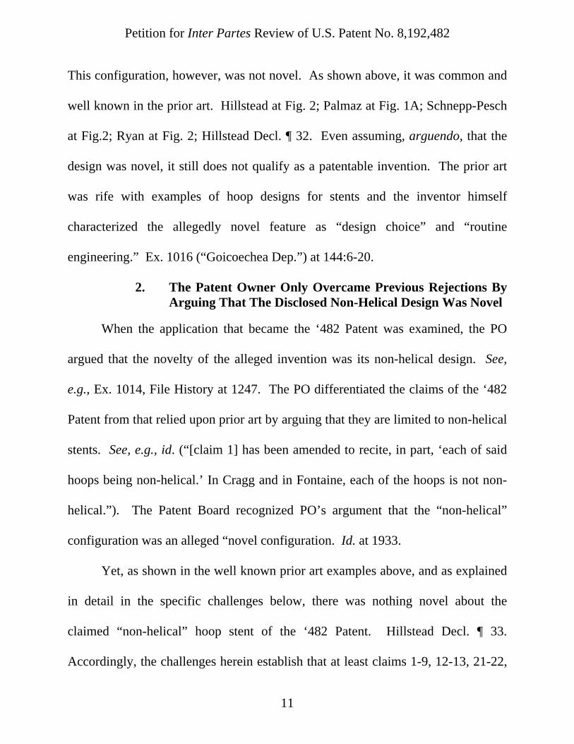
This configuration, however, was not novel. As shown above, it was common and
well known in the prior art. Hillstead at Fig. 2; Palmaz at Fig. 1A; Schnepp-Pesch
at Fig.2; Ryan at Fig. 2; Hillstead Decl. ¶ 32. Even assuming, arguendo, that the
design was novel, it still does not qualify as a patentable invention. The prior art
was rife with examples of hoop designs for stents and the inventor himself
characterized the allegedly novel feature as “design choice” and “routine
engineering.” Ex. 1016 (“Goicoechea Dep.”) at 144:6-20.
2. The Patent Owner Only Overcame Previous Rejections By Arguing That The Disclosed Non-Helical Design Was Novel
When the application that became the ‘482 Patent was examined, the PO
argued that the novelty of the alleged invention was its non-helical design. See,
e.g., Ex. 1014, File History at 1247. The PO differentiated the claims of the ‘482
Patent from that relied upon prior art by arguing that they are limited to non-helical
stents. See, e.g., id. (“[claim 1] has been amended to recite, in part, ‘each of said
hoops being non-helical.’ In Cragg and in Fontaine, each of the hoops is not non-
helical.”). The Patent Board recognized PO’s argument that the “non-helical”
configuration was an alleged “novel configuration. Id. at 1933.
Yet, as shown in the well known prior art examples above, and as explained
in detail in the specific challenges below, there was nothing novel about the
claimed “non-helical” hoop stent of the ‘482 Patent. Hillstead Decl. ¶ 33.
Accordingly, the challenges herein establish that at least claims 1-9, 12-13, 21-22,

Petition for Inter Partes Review of U.S. Patent No. 8,192,482
12
and 30 are unpatentable.
3. Elements from Helical and Non-Helical Stents Were Known To be Interchangeable
The ‘482 Patent specification describes both helical and non-helical
embodiments. ‘482 Patent at 3:62-4:7. Importantly, the ‘482 Patent and the prior
art make clear that well known elements disclosed as part of helical stents could be
simply substituted into non-helical stents. Hillstead Decl. ¶ 33; see also Ex. 1016
(“Goicoechea Dep.”) at 144:6-20; see also Ex. 1014, File History at 1693.
For example, as shown above, both helical and non-helical prior art stents
could have zig-zag patterns whereby adjacent apices abut.
Cragg at Fig. 1; Ryan at Fig. 2; Hillstead Decl. ¶ 34. These patterns were well
known in the prior art and, as discussed below, various means for securing abutting
apices was also well known in the prior art. Hillstead Decl. ¶¶ 34, 46. Further, it
was well known that those securing means were interchangeable not only with one
Helical Prior Art (Cragg) Apices abut and are connected/secured
Non- Helical Prior Art (Ryan) Apices abut and are connected/secured

Petition for Inter Partes Review of U.S. Patent No. 8,192,482
13
another, but between helical and non-helical designs. Id. at ¶ 35. Specifically, one
of skill in the art would have been capable of implementing the securing means
from the non-helical design of Cragg into the helical design of Ryan because it
would have been nothing more than a simple substitution of one well known
securing means for another well known securing means that would have achieved a
predictable result. Id.
In sum, at the time of the alleged invention of the ‘482 Patent there was
nothing novel about using a helical design, nothing novel about using a non-helical
design, and nothing novel about implementing well known prior art elements into
either helical or non-helical designs. Id. at ¶ 36.
4. Well Known, Interchangeable Prior Art Securing Means
In addition to claiming a non-helical stent design, the ‘482 Patent claims
“means for securing an apex of one hoop to an abutting a juxtaposed apex of a
neighboring hoop.” This too was a well known prior art feature of both helical and
non-helical stent designs. Id. at ¶ 37.
As briefly described above, it was well known to align the apices of one
layer of zig-zags with the apices of an adjacent layer of zig-zags in both helical and
non-helical designs. Id. at ¶ 38. It was common to align apices in order to secure
the layers together at the apices where the securing means would be most effective.
This practice was well known as early as the 1980s by virtue of, at least, Palmaz.

Petition for Inter Partes Review of U.S. Patent No. 8,192,482
14
Palmaz at 6:36-52. Because this practice was so common well before the ‘482
Patent, a variety of well known means for securing apices had been established
prior to the filing date of the ‘482 Patent. Hillstead Decl. ¶ 39. The various
securing means all shared a common function: to secure an apex of one hoop to an
abutting juxtaposed apex of a neighboring hoop. Id.
The ‘482 Patent recognized that such means for securing were well known
prior art elements at the time of the alleged invention and did not characterize them
as new or novel. Id. at ¶ 40. Specifically, the ‘482 Patent states: “Typically, the
stents of this invention whether of the helical or perpendicular variety, also
comprise a securing means for securing an apex of the sinuous wire in one hoop to
a juxtaposed apex of a neighboring hoop so that each hoop is supported by its
neighbors.” ‘482 Patent at 4:21-25.
The following prior art examples not only disclose several of the well known
prior art structures for securing apices, they also recognize the interchangeability
of such structures. Hillstead Decl. ¶ 41.
Palmaz discloses use of “welding, soldering, or gluing” or any other
“conventional manner” for securing apices in order to provide “a relatively high
resistance to radial collapse” and to allow the stent to retain its shape. Palmaz at
6:36-49; Hillstead Decl. ¶ 42.
Fontaine discloses using a loop or a staple-like bracket to secure apices in

Petition for Inter Partes Review of U.S. Patent No. 8,192,482
15
addition to brazing, welding or gluing: “In practice, the connection between the
loop and the filament is slidable along the filament 11, thereby allowing for radial
expansion. Although this connection can be easily made using a loop as shown, it
can also be made by, for example, using a bracket. The connector could also be
made by brazing, welding, or gluing the end to the filament.” Fontaine at 4:59-63;
Hillstead Decl. ¶ 43.
Cragg discloses using “loops which connect adjacent apices of the wire.”
Cragg at Abstract; Hillstead Decl. ¶ 44. Cragg further discloses “loop members 12
which connect adjacent apices of adjacent helix hoops to help define the tubular
stent. The loop members 12 may connect all or some of the pairs of adjacent
apices.” Cragg at 2:42-47; Hillstead Decl. ¶ 44. This disclosure is further depicted
in the figures of Cragg.
Cragg at Figs. 2-4; Hillstead Decl. ¶ 44.
Lau discloses that the apices may be secured integrally or by independent
means: “The interconnecting elements may be formed in a unitary structure with
the expandable cylindrical elements from the same intermediate product, such as a

Petition for Inter Partes Review of U.S. Patent No. 8,192,482
16
tubular element, or they may be formed independently and connected by suitable
means, such as by welding or by mechanically securing the ends of the
interconnecting elements to the ends of the expandable cylindrical elements.” Lau
at 2:59-66; Hillstead Decl. ¶ 45.
Andersen discloses that “an improved stent structure that is formed of a self-
expending filament material in loosely interlocked loops.” Andersen at 3:16-18.
D. Summary of the Prosecution of the ‘482 Patent
The application that issued as the ‘482 Patent, U.S. Application No.
09/977,826, filed October 15, 2001, is a continuation of U.S. Application No.
09/313,593, now U.S. Patent No. 6,302,906 (“‘906 Patent”), filed May 18, 1999,
which is a continuation of U.S. Application No. 08/662,484, now U.S. Patent No.
5,916,263, filed June 13, 1995, which is a continuation of U.S. Application No.
08/317,763, now U.S. Patent No. 5,609,627, filed Oct. 4, 1994, which is a
continuation of U.S. Application No. 08/312,881, now abandoned, filed Sept. 27,
1994. The examiner did not use Ryan, Hillstead or any other combinations offered
herein as the basis for any rejection. See Ex. 1014, File History.
E. The ‘482 Patent Cannot Claim Priority to EP 94400284 or EP 94401306
The ‘482 Patent is a continuation of the ‘906 Patent, which is a continuation
of U.S. Application No. 08/662,484, now U.S. Patent No. 5,916,263, (“‘484
Application”), which is a continuation of U.S. Application No. 08/317,763, now

Petition for Inter Partes Review of U.S. Patent No. 8,192,482
17
U.S. Patent No. 5,609,627 (“‘763 Application”). Another division of the ‘763
Application, U.S. Application No. 08/461,402 (the “‘402 Application,” or
“Goicoechea”), was the subject of an interference before the BPAI, No. 104,192
(“‘192 Interference”). Based on this interference and subsequent district court and
Federal Circuit litigation, it is conclusive that the ‘482 Patent cannot claim priority
to EP 94400284 (“EP ‘284”) or EP 94401306 (“EP ‘306”).
The ‘192 Interference was declared on April 23, 1998, among Goicoechea
and (1) U.S. Application No. 08/463,836 (“the Ryan Patent”), and (2) U.S. Patent
No. 5,575,817 to Eric Martin (“the Martin Patent”).1 In the course of the ‘192
Interference, the BPAI found that the Goicoechea ‘402 Application was not
entitled to claim priority to the MinTec EPO Applications under 35 U.S.C. § 119.
The BPAI determined that because two of the inventors on the Goicoechea ‘402
Application, Michael Dake and Andrew Cragg, did not assign their rights to
MinTec SARL until after the filing of the MinTec EPO Applications, the MinTec
EPO Applications were not filed on Dake’s or Cragg’s behalf as required by 35
U.S.C. § 119, and thus the Goicoechea ‘402 Application could not claim priority to
the MinTec EPO Applications. Ex. 1017, BPAI Decision, April 7, 2000, at 6.
1 Because of corrections of inventorship, Goicoechea is often referred to in the
‘192 Interference as “Cragg,” and Ryan is referred to as “Fogarty.” The Ryan
‘836 application ultimately issued as U.S. Patent No. 8,206,427.

Petition for Inter Partes Review of U.S. Patent No. 8,192,482
18
This determination was affirmed by the United States District Court for the District
of Columbia and the Federal Circuit. Exs. 1018, 1019. Accordingly, all patents in
the Goicoechea patent family that list Dake or Cragg as an inventor cannot claim
priority to the EP applications.
F. Related ‘167 Patent IPR and Institution Decision
On August 18, 2014, W.L. Gore & Associates, Inc., filed a petition for Inter
Partes Review of U.S. Patent No. 6,117,167 (“‘167 Patent”). The ‘167 Patent
claims priority back to the same application at the ‘482 Patent, U.S. Application
No. 08/312,881, now abandoned, filed Sept. 27, 1994. On February 23, 2015, the
Patent Trial and Appeal Board (“PTAB”) instituted the inter partes review on
claims 1-82 (i.e. all the claims). That proceeding included instituted grounds for
claims similar to the claims of the ‘482 Patent. Compare claim 1 of the ‘482
Patent with claims 35-37 of the ‘167 Patent (Ex. 1020) and IPR2014-01319, Paper
No. 7, Institution Decision at 16 (PTAB Feb. 23, 2015) (Ex. 1021).
VII. PERSON OF ORDINARY SKILL IN THE ART
A person of ordinary skill in the art is a hypothetical person presumed to
know the relevant prior art. Gnosis S.p.A. v. South Alabama Med. Sci. Found.,
IPR2013-00116, Final Written Decision (Paper 68) at 9. Such a person is of
ordinary creativity, not merely an automaton, and is capable of combining
teachings of the prior art. Id. (citing KSR Int’l Co. v. Teleflex Inc., 550 U.S. 398,

Petition for Inter Partes Review of U.S. Patent No. 8,192,482
19
420-21 (2007).) Petitioner submits that a person of ordinary skill in the art of the
‘482 Patent as of September 27, 1994, would have had a bachelor of science
degree in mechanical engineering, or the equivalent, or would have had at least
five years of experience in designing stents. Hillstead Decl. ¶¶ 1-20.
VIII. CLAIM CONSTRUCTION
In the pending district court litigation, the parties agreed to constructions for
some terms in the ‘482 Patent. Normally, a claim in inter partes review is given
the “broadest reasonable construction in light of the specification.” See 37 C.F.R §
42.100(b). However, the ‘482 Patent expired on September 27, 2014. 35 U.S.C. §
154(a). Accordingly, where a challenged patent is expired, the standard set forth in
Phillips applies. See Toyota Motor Corp. v. Leroy G. Hagenbuch, Case IPR2013-
00483, Paper 37 (PTAB Dec. 5, 2014).
Here, a person of ordinary skill in the art at the time of the alleged invention
would have understood each term of each claim of the ‘482 Patent to have its plain
and ordinary meaning, or alternatively, that which was agreed to in the Joint Claim
Chart filed in the District Court Case (Dkt. No. 57). The agreed constructions are
as follows:
Claim(s) Claim Term Construction
1-9, 12-13, 21-22
“non-helical” non-spiral
1-9, 12-13, “means for Function: Securing the apex of one hoop to a juxtaposed apex of a

Petition for Inter Partes Review of U.S. Patent No. 8,192,482
20
21-22 securing” neighboring hoop.
Structure: (1) loop formed of thermoplastic material; (2) a suture; (3) bead formed of a thermoplastic material; (4) loop formed of wire; (5) ring formed of wire; and (6) staple formed of wire; and equivalents.
Patent Owner has further argued for a broad interpretation of equivalent structures that includes a wire structure that is integral with the apices of juxtaposed hoops. See Infringement Contentions at 009-010 (Ex. 1022).
A. Additional Terms for Construction
1. “segment” (Claims 2-5,8-9, and 12)
In addition to the agreed constructions, Petitioner submits that the claim
term “segment” (see Claims 2-5, 8-9, and 12) means “portion.” The ‘482 Patent
makes clear that those terms are synonymous when used to describe a segment or
portion of a stent: “straight stent 400 comprises proximal stent portion (or
segment) 401, distal stent portion 402, and an intermediate portion 403.” ‘482
Patent at 16:33-35 (emphasis added).
Petition for Inter Partes Review of U.S. Patent No. 8,192,482
21
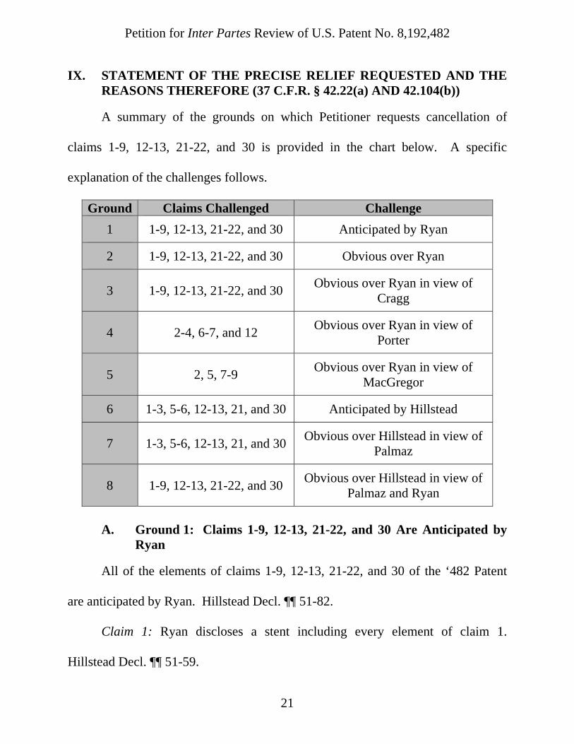
IX. STATEMENT OF THE PRECISE RELIEF REQUESTED AND THE REASONS THEREFORE (37 C.F.R. § 42.22(a) AND 42.104(b))
A summary of the grounds on which Petitioner requests cancellation of
claims 1-9, 12-13, 21-22, and 30 is provided in the chart below. A specific
explanation of the challenges follows.
Ground Claims Challenged Challenge
1 1-9, 12-13, 21-22, and 30 Anticipated by Ryan
2 1-9, 12-13, 21-22, and 30 Obvious over Ryan
3 1-9, 12-13, 21-22, and 30 Obvious over Ryan in view of
Cragg
4 2-4, 6-7, and 12 Obvious over Ryan in view of
Porter
5 2, 5, 7-9 Obvious over Ryan in view of
MacGregor
6 1-3, 5-6, 12-13, 21, and 30 Anticipated by Hillstead
7 1-3, 5-6, 12-13, 21, and 30 Obvious over Hillstead in view of
Palmaz
8 1-9, 12-13, 21-22, and 30 Obvious over Hillstead in view of
Palmaz and Ryan
A. Ground 1: Claims 1-9, 12-13, 21-22, and 30 Are Anticipated by
Ryan
All of the elements of claims 1-9, 12-13, 21-22, and 30 of the ‘482 Patent
are anticipated by Ryan. Hillstead Decl. ¶¶ 51-82.
Claim 1: Ryan discloses a stent including every element of claim 1.
Hillstead Decl. ¶¶ 51-59.

Petition for Inter Partes Review of U.S. Patent No. 8,192,482
22
Claim 1 Ryan
[1.0] A stent comprising:
[1.1] a plurality of hoops aligned along a common axis,
[1.2] each of said hoops being non-helical and oriented in a plane substantially perpendicular to the longitudinal axis of the stent, and
[1.3] each of said hoops including a plurality of elongate elements joined to one another and forming apices that point in a direction along the longitudinal axis of the stent, and
[1.4] wherein at least one elongate element in each hoop is a continuation of an elongate element of an adjacent hoop; and
[1.5] means for securing an apex of one hoop to an abutting a juxtaposed apex of a neighboring hoop.
Ryan describes a stent comprised of either non-helical or helical elements.
Ryan at 5:24-30; Hillstead Decl. ¶ 52. Specifically, Ryan discloses that “[t]he
radially compressible frame can take a variety of forms, usually comprising or
[1.5] means for securing 13 apices of neighboring hoops
[1.1] hoops 11
[1.3] elongate element
[1.2] non-helical hoop 11 in
perpendicular plane
[1.3] apex pointing in direction along stent axis
[1.0] Tubular Stent Frame (Ryan, Fig. 2)
[1.1] common axis
[1.3/1.4] elongate element continues from one hoop
to an adjacent hoop

Petition for Inter Partes Review of U.S. Patent No. 8,192,482
23
consisting of a plurality of independent or interconnected structural elements, such
as rings, bands, helical elements, serpentine elements, axial struts, parallel bars,
and the like.” Ex. 1004 at 5:24-30; Hillstead Decl. ¶ 53. The preferred
embodiments of Ryan depict and describe non-helical rings (i.e., hoops). Ryan
explicitly discloses that “[t]he tubular frame preferably comprises a plurality of
radially compressible band or ring structures.” Ryan at 3:16-17; Hillstead Decl. ¶
53. Ryan depicts its “band or ring structures” as non-helical rings that are each
oriented in a plane perpendicular to the axis of the stent. See, eg., Ryan at Fig. 2;
Hillstead Decl. ¶ 53. Ryan discloses that “band members 11, each [] comprise[] a
zig-zag or Z-shaped element which forms a continuous circular ring.” Ryan at
7:49-52; Hillstead Decl. ¶ 53. For example, as shown above, Figure 2 of Ryan
depicts nine axially aligned hoops (“band members 11”), each oriented in a plane
perpendicular to the longitudinal axis of the stent. Ryan at Fig. 2; Hillstead Decl. ¶
54. Ryan also describes and shows that its hoops are oriented in a conventional
“zig-zag” pattern constructed of elongate elements that meet at apices and shows
that the apices point in a direction along the longitudinal axis of the stent. Ryan at
7:49-51, Figs. 1-5; Hillstead Decl. ¶ 54. Accordingly, Ryan discloses claim 1’s
limitations of [1.1] “a plurality of hoops aligned along a common axis,” [1.2] “each
of said hoops being non-helical and oriented in a plane substantially perpendicular
to the longitudinal axis of the stent,” and [1.3] “each of said hoops including a
Petition for Inter Partes Review of U.S. Patent No. 8,192,482
24
plurality of elongate elements joined to one another and forming apices that point
in a direction along the longitudinal axis of the stent.” Ryan at 3:16-19, 7:49-61,
Figs. 1-5; Hillstead Decl. ¶¶ 52-55.
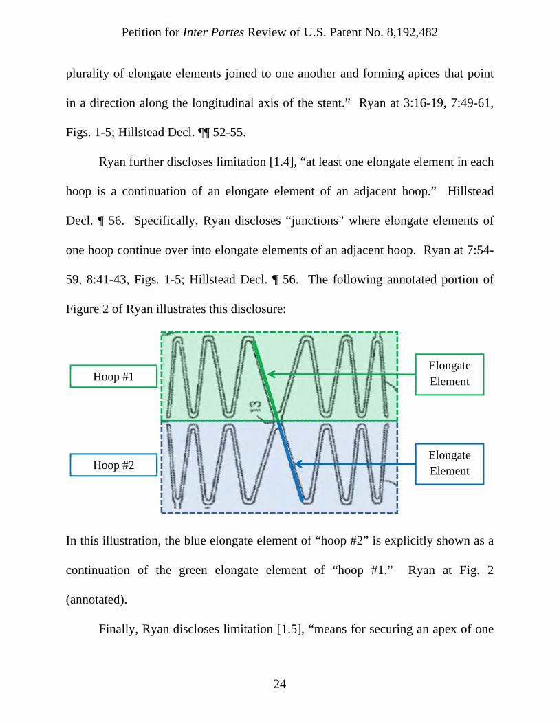
Ryan further discloses limitation [1.4], “at least one elongate element in each
hoop is a continuation of an elongate element of an adjacent hoop.” Hillstead
Decl. ¶ 56. Specifically, Ryan discloses “junctions” where elongate elements of
one hoop continue over into elongate elements of an adjacent hoop. Ryan at 7:54-
59, 8:41-43, Figs. 1-5; Hillstead Decl. ¶ 56. The following annotated portion of
Figure 2 of Ryan illustrates this disclosure:
In this illustration, the blue elongate element of “hoop #2” is explicitly shown as a
continuation of the green elongate element of “hoop #1.” Ryan at Fig. 2
(annotated).
Finally, Ryan discloses limitation [1.5], “means for securing an apex of one
Hoop #1
Hoop #2
Elongate Element
Elongate Element

Petition for Inter Partes Review of U.S. Patent No. 8,192,482
25
hoop to an abutting juxtaposed apex of a neighboring hoop.” Specifically Ryan is
clear that “[a]djacent compressible band members . . . may be joined at one or
more locations therebetween.” Ryan at 3:19-21; Hillstead Decl. ¶ 57. Ryan also
discloses that “the bands are preferably joined at [] diametrically opposed points,”
i.e., apices. Ryan at 3:22-23; Hillstead Decl. ¶57. Ryan’s “bridge element”
preforms an identical function as claim 1’s “means for securing,” i.e., it secures the
apex of one hoop to a juxtaposed apex of a neighboring hoop. Ryan at 3:19-23,
7:49-57, Figs. 1-5; Hillstead Decl. ¶ 57. While the structure of Ryan’s “bridge
element 13” may not identical to the structures disclosed in the ‘482 Patent, the
‘482 Patent does not make any statements that would foreclose on Ryan’s “bridge
element 13” being an equivalent structure such that it anticipates this element. 35
U.S.C. §112(f); Hillstead Decl. ¶¶ 58-59; see also Ex. 1022. Indeed, as explained
above, PO has argued that an integral wire connecting the apex of one hoop to a
juxtaposed apex meets this limitation. Ex. 1022, Infringement Contentions at 009-
010.
Claim 2: Claim 2 depends from claim 1 and requires that “at least one stent
segment in combination with one or more additional stent segments.” Ryan
discloses several variations of a stent segment in combination with additional stent
segments. Hillstead Decl. ¶¶ 60-62.
First, Ryan discloses that its “tubular frame” (stent) may be constructed of

Petition for Inter Partes Review of U.S. Patent No. 8,192,482
26
multiple stent segments with varying properties. Ryan at 6:62-7:39; Hillstead
Decl. ¶ 61. For example, Ryan discloses that “some circumferentially spaced-apart
segments of the tubular frame could be malleable while the remaining
circumferential segments would be elastic.” Ryan at 7:19-22; Hillstead Decl. ¶ 61.
This can be achieved “by forming circumferential segments of the frame from
different materials having different elastic/malleable properties.” Ryan at 7:32-36;
Hillstead Decl. ¶ 61. By this disclosure alone, Ryan anticipates claim 2. Id.
Second, in Figure 12 for example, Ryan discloses a bifurcated stent structure
where a base stent segment 20 is used in combination with additional leg segments
10. Ryan at 10:23-50, Figs. 7-12. Hillstead Decl. ¶ 62. By this disclosure alone,
Ryan anticipates claim 2. Id.
Claim 3: Claim 3 depends from claim 2 and requires that “said one or more
additional segments are axially aligned with one another.” Ryan’s disclosure of
segments of its tubular member with “different elastic or other mechanical
properties at different regions along its length” anticipates claim 3. Ryan at 6:62-
7:39; Hillstead Decl. ¶ 63. Ryan provides a specific example of a “malleable” end
segment and an “elastic” middle segment. Ryan at 6:67-7:8; Hillstead Decl. ¶ 64.
Ryan contemplates these segments would be part of the same tubular member and
thus share a longitudinal axis. Ryan at 6:62-7:39; Hillstead Decl. ¶ 64. Thus Ryan
discloses that “said one or more additional segments are axially aligned with one

Petition for Inter Partes Review of U.S. Patent No. 8,192,482
27
another.” Hillstead Decl. ¶¶ 63-64.
Additionally, as shown in Figure 12 of Ryan, the additional leg segments 10
of the bifurcated device are axially aligned with the body segment 20. This
disclosure of Ryan also anticipates claim 3. Hillstead Decl. ¶ 65.
Claim 4: Claim 4 depends from claim 3 and requires that “said axially
aligned segments are connected to one another by a tubular fabric element.”
Ryan’s stent segments with “different elastic or other mechanical properties,”
described above, are connected by a tubular fabric element(s). Hillstead Decl. ¶
66. Ryan discloses tubular fabric elements traversing the interior and exterior of
its stent. Ryan at 7:62-9:5, Figs. 1, 1A; Hillstead Decl. ¶ 66. Specifically, Ryan
discloses “fabric liner 12” depicted in Figure 1. Ryan at 7:40-48, Fig. 1. Ryan
also discloses an “outer liner 110” in conjunction with “inner liner 108” as
depicted in Figure 1A. Ryan at 8:47-9:5, Fig. 1A; Hillstead Decl. ¶ 67. In each of
these embodiments, the stent segments are connected by the inner and/or outer
“tubular fabric element” which are “stitched or otherwise secured to the band
members 11, preferably at the junctions or nodes.” Ryan at 7:64-67, Figs. 1, 1A;
Hillstead Decl. ¶ 67. Ryan also discloses that the additional leg segments 10 of the
bifurcated device shown in Figure 12 are connected to the body segment 20 by
tubular fabric elements 26, 28. Ryan at 10:23-50, Figs 7-12; Hillstead Decl. ¶67.
Each of these disclosures anticipates claim 4. Hillstead Decl. ¶¶ 66-67.

Petition for Inter Partes Review of U.S. Patent No. 8,192,482
28
Claim 5: Claim 5 depends from claim 2 and requires that “said one or more
additional segments are secured to one another by connecting means connecting at
least some of the apices of hoops at mating ends of said stent and said additional
segments.” Ryan’s stent segments with “different elastic or other mechanical
properties,” described above, may be secured to one another by connecting means
connecting at least some of the apices of hoops at mating ends, as depicted in
Figures 1-5 of Ryan. Hillstead Decl. ¶ 68. For example, Ryan discloses that
“some circumferentially spaced-apart segments of the tubular frame could be
malleable while the remaining circumferential segments would be elastic.” Ryan
at 7:19-22; Hillstead Decl. ¶ 69. The end most hoops or bands of each segment are
connected in the same manner as generally disclosed hoops or bands, i.e., by
connecting elements 13. Ryan at 7:54-57, Figures 1-2; Hillstead Decl. ¶ 69.

Petition for Inter Partes Review of U.S. Patent No. 8,192,482
29
Ryan at 6:67-7:17, Figs. 1-5; Hillstead Decl. ¶ 69.
Claim 6: Claim 6 depends from claim 2 and requires that “adjacent hoops
are of the same diameter.” This claim does not modify the elements added by
claim 2, but rather refers to the claimed “hoops” of claim 1. Hillstead Decl. ¶ 70.
As shown throughout, the main tubular member of Ryan is depicted as having
adjacent hoops (band members 11) of the same diameter. Ryan at Figs. 1-5;
Hillstead Decl. ¶ 70. Ryan also discloses that adjacent hoops of separate segments
Malleable end segment
Elastic middle segment
Malleable end segment
Embodiment disclosed by Ryan at
6:67-7:17
Connecting means 13
Connecting means 13

Petition for Inter Partes Review of U.S. Patent No. 8,192,482
30
are of the same diameter. See analysis of claim 5 above; Ryan at 6:67-7:17, Figs.
1-5; Hillstead Decl. ¶¶ 68-70.
Claim 7: Claim 7 depends from claim 2 and requires that “adjacent hoops
are of a different diameter.” Figure 12 of Ryan depicts integrally larger hoop
diameters from the proximal end to the distal end of stent 10. Hillstead Decl. ¶ 71.
Ryan at Fig. 12. Because the diameters of the proximal-most hoop and the distal-
most hoop are different, at least one set of adjacent hoops must be of a different
diameter. Hillstead Decl. ¶ 71. It appears that the diameter of the hoops increases
gradually, and thus, each set of adjacent hoops are of a different diameter in this
Proximal hoop diameter
Distal hoop diameter

Petition for Inter Partes Review of U.S. Patent No. 8,192,482
31
embodiment. Ryan at Fig. 12; Hillstead Decl. ¶ 71.
Claim 8: Claim 8 depends from claim 2 and requires that “a first additional
segment is axially parallel to, but non-common co-axial with, said stent segment.”
As described above with respect to claim 3, in Figure 12 of Ryan, the additional
leg segments 10 of the bifurcated device are axially aligned with the body segment
20. Hillstead Decl. ¶ 72. Those leg segments 10 are axially parallel to, but non-
common co-axial with, the body stent segment 20. Id.
Claim 9: Claim 9 depends from claim 8 and requires that “a second
additional segment axially parallel to said stent segment, but non-co-axial with
either said stent segment or said first additional stent segment.” As described
above with respect to claims 3 and 8, in Figure 12 of Ryan, the additional leg
segments 10 of the bifurcated device are axially parallel to the body segment 20.
Hillstead Decl. ¶ 73. Those leg segments 10 are axially parallel to, but non-
common co-axial with, the body stent segment 20. Ryan at Fig. 12; Hillstead Decl.
¶ 73. Additionally, the two leg segments 10, 10 are non-co-axial with each other.
Hillstead Decl. ¶ 74. Thus if the leg segment 10 in LI of Figure 12 is the first
additional stent segment and the leg segment 10 in RI of Figure 12 is the second
additional stent segment, the “second additional segment axially parallel to said
stent segment, but non-co-axial with either said stent segment or said first
additional stent segment.” Ryan at Fig. 12; Hillstead Decl. ¶ 74.

Petition for Inter Partes Review of U.S. Patent No. 8,192,482
32
Claim 12: Claim 12 depends from claim 2 and requires that “at least one of
said additional stent segments comprises:
[12.1] a plurality of hoops aligned along a common axis,
[12.2] each of said hoops oriented in a plane substantially perpendicular to
the longitudinal axis of the additional stent segment,
[12.3] and each of said hoops including a plurality of elongate elements
joined to one another and forming apices that point in a direction along the
longitudinal axis of the additional stent segment; and
All three segments have parallel axes, but none of
them are co-axial

Petition for Inter Partes Review of U.S. Patent No. 8,192,482
33
[12.4] means for securing an apex of one hoop to a juxtaposed apex of a
neighboring hoop.”
As discussed above with respect to claims 2-5 and as shown in the
discussion of claim 5, Ryan’s additional stent segments with “different elastic or
other mechanical properties,” may be constructed in the same way as the main
stent segment such that they meet the additional limitations of claim 12 for the
same reasons the stent limitations claimed in claim 1 are disclosed by Ryan.
Hillstead Decl. ¶ 75. The additional limitations of claim 12, [12.1], [12.2], [12.3],
[12.4], mirror limitations [1.1], [1.2], [1.3], [1.5] of claim 1. Thus, claim 12 is also
anticipated by Ryan. Hillstead Decl. ¶ 75.
Claim 13: Claim 13 depends from claim 1 and requires that “said hoops are
formed of a single continuous wire.” Ryan depicts a stent with hoops are formed
of a single continuous wire. Hillstead Decl. ¶ 76. Specifically, Ryan discloses that
its hoops (band members 11) “comprise a zig-zag or Z-shaped element which
forms a continuous circular ring.” Ryan at 7:49-52, Fig. 1-3; Hillstead Decl. ¶ 76.
That continuous circular ring is depicted as a single zig-zaging wire in Figures 1-3.
Claim 21: Claim 21 depends from claim 1 and requires that “each
longitudinal end of the stent is substantially perpendicular square to the
longitudinal axis of the stent.” Ryan depicts and describes that “each longitudinal
end of the stent is substantially perpendicular square to the longitudinal axis of the

Petition for Inter Partes Review of U.S. Patent No. 8,192,482
34
stent.” See, e.g., Ryan at Figure 2 (annotated); Hillstead Decl. ¶ 77.
Claim 22: Claim 22 depends from claim 1 and requires that “said stent is at
least partially covered in fabric.” Ryan discloses that its stent is at least partially
covered by outer liner 110 in Figure 1A. Ryan at 8:47-9:5, Fig. 1A; Hillstead
Decl. ¶ 78. Outer liner 110 is a fabric. Ryan at 8:64-66; Hillstead Decl. ¶ 78.
Claim 30: Claim 30 is an independent claim that includes limitations from
claim 1, but does not include the means plus function language of element 1.5.
Rather, it merely requires “wherein at least some of said vertices axially abut and
are individually connected to oppositely pointed vertices of elongate elements of
an adjacent hoop.” Hillstead Decl. ¶ 79. Thus, there is no need to look to the ‘482
longitudinal axis
longitudinal end
longitudinal end

Petition for Inter Partes Review of U.S. Patent No. 8,192,482
35
Patent specification’s specifically disclosed and equivalent securing structures to
determine anticipation. Id. As shown above, Ryan discloses that abutting vertices
are individually connected by “junctions 13,” satisfying element [30.3] of claim 30
(listed below) for the reasons stated herein. Id. at ¶ 80.
Claim 1 Claim 30
[1.0] A stent comprising: [30.0] A stent comprising a tubular member having
[1.1] a plurality of hoops aligned along a common axis,
[30.1] a plurality of hoops aligned adjacent one another along the longitudinal axis of the tubular member,
[1.2] each of said hoops being non-helical and oriented in a plane substantially perpendicular to the longitudinal axis of the stent, and
[1.3] each of said hoops including a plurality of elongate elements joined to one another and forming apices that point in a direction along the longitudinal axis of the stent, and
[30.2] said hoops comprising a plurality of elongate elements, with pairs of said elongate elements meeting one another and forming vertices axially pointing in a direction along the longitudinal axis of the stent
[1.5] means for securing an apex of one hoop to an abutting a juxtaposed apex of a neighboring hoop.
[30.3] wherein at least some of said vertices axially abut and are individually connected to oppositely pointed vertices of elongate elements of an adjacent hoop,
[30.4] wherein the vertices of each hoop pointed in the axial direction lie in a common plane perpendicular to the longitudinal axis of the tubular member
[1.4] wherein at least one elongate element in each hoop is a continuation of an elongate element of an adjacent hoop; and
[30.5] and wherein at least one elongate element in each hoop is a continuation of an elongate element of an adjacent hoop.

Petition for Inter Partes Review of U.S. Patent No. 8,192,482
36
Elements [30.1], [30.2], [30.3], and [30.5] of claim 30 correspond to
elements claimed in claim 1. Hillstead Decl. ¶ 80. For the same reasons Ryan
discloses the corresponding elements of claim 1, it discloses elements [30.1],
[30.2], [30.3], and [30.5] of claim 30. Id. Claim 30 also requires element [30.4]:
“the vertices of each hoop pointed in the axial direction lie in a common plane
perpendicular to the longitudinal axis of the tubular member.” Ryan discloses this
additional element. Ryan at 7:49-54, Fig 2; Hillstead Decl. ¶ 81.
For this reason and for those stated regarding the limitations of claim 1, Ryan
anticipates claim 30. Hillstead Decl. ¶¶ 79-81.
longitudinal axis
Vertices in a common plane perpendicular to the longitudinal axis

Petition for Inter Partes Review of U.S. Patent No. 8,192,482
37
B. Ground 2: Claims 1-9, 12-13, 21-22, and 30 Are Obvious Over Ryan
To the extent any claim is not anticipated by Ryan, it is at least rendered
obvious by Ryan in view of the well known prior art. Hillstead Decl. ¶¶ 83-87.
One of skill in the art would have found it obvious to implement predictable
variations of Ryan that cover every claim of the ‘482 Patent. See Sciele Pharma,
Inc. v. Lupin Ltd., 684 F.3d 1253, 1260 (Fed. Cir. 2012) (“The obviousness
analysis entails ‘an expansive and flexible approach.’. . . ‘If a person of ordinary
skill can implement a predictable variation, § 103 likely bars its patentability.’”)
(quoting KSR Int’l Co. v. Teleflex, Inc., 550 U.S. 398, 416); Hillstead Decl. ¶ 83.
Element [1.5]/[30.3] of Claims 1 and 30 - As discussed above, Ryan
discloses a “means for securing an apex of one hoop to an abutting a juxtaposed
apex of a neighboring hoop.” Ryan at 3:19-23, 7:49-57, Figs. 1-5; Hillstead Decl.
¶ 84. To the extent Ryan does not disclose a structure equivalent to the structures
disclosed in the ‘482 Patent “for securing an apex of one hoop to an abutting a
juxtaposed apex of a neighboring hoop,” one of skill in the art would have known
to make the simple modification using one of the well known prior art securing
structures at the junctions 13 of Ryan. Hillstead Decl. ¶ 85. As discussed above, a
number of securing structures were well know to be used to “secur[e] an apex of
one hoop to an abutting a juxtaposed apex of a neighboring hoop.” Id. at ¶ 86.
These well know prior art structures for securing included loops formed of

Petition for Inter Partes Review of U.S. Patent No. 8,192,482
38
thermoplastic material or wire, sutures, wire rings, and wire staples. Id. Each of
those well know prior art structures are disclosed by the ‘482 Patent as structures
capable of preforming the claimed function of “securing an apex of one hoop to an
abutting a juxtaposed apex of a neighboring hoop.” Id.
C. Ground 3: Claims 1-9, 12-13, 21-22, and 30 Are Obvious Over Ryan In View Of Cragg
To the extent any claim is not anticipated by Ryan, it is at least rendered
obvious by Ryan in view of Cragg. Hillstead Decl. ¶¶ 88-93.
Element [1.5]/[30.3] of Claims 1 and 30 - Cragg is a prior art stent design
wherein a zig-zag pattern is wrapped around a longitudinal axis such that adjacent
apices pointed in the axial direction abut one another. Cragg at 2:20-65, Figs. 1-4;
Hillstead Decl. ¶ 89. Cragg discloses “means for securing an apex of one hoop to
an abutting a juxtaposed apex of a neighboring hoop” for the same reasons as Ryan
and to provide the same function claimed in claim 1 of the ‘482 Patent. Hillstead
Decl. ¶ 89. Specifically, the claimed function of the “means for securing” of claim
1 of the ‘482 Patent is to “secur[e] the apex of one hoop to a juxtaposed apex of a
neighboring hoop.” Id.
Ryan discloses and shows that “bridge elements 13” secure “diametrically
opposed points” (i.e., abutting apices). Ryan at 5:34-37, 7:7:54-57, Figs. 1-3;
Hillstead Decl. ¶ 90. While Ryan’s “bridge elements 13” are equivalents to the
securing structures disclosed in the ‘482 Patent, Cragg discloses several of the

Petition for Inter Partes Review of U.S. Patent No. 8,192,482
39
explicitly defined securing structures of ‘482 Patent. Hillstead Decl. ¶ 90. Cragg
discloses: “loop members 12 which connect adjacent apices of adjacent helix
hoops to help define the tubular stent.” Cragg at 2:45-49; Hillstead Decl. ¶ 91.
Cragg discloses several well known securing structures that are common with
those defined in the ‘482 Patent: “[a]lthough sutures are the preferred connecting
means, other connecting means such as staples and rings made of metal or plastic
may provide the same function.” Cragg at 3:1-4; Hillstead Decl. ¶ 91. The
“function” of the securing means disclosed by Cragg is to “connect all or some of
the pairs of adjacent apices.” Cragg at 2:60-62, Figs. 2-4; Hillstead Decl. ¶91.
It would have been a simple substitution for one of skill in the art to use the
securing means disclosed in Cragg to achieve the predictable result of “securing
the apex of one hoop to a juxtaposed apex of a neighboring hoop” in place of the
equivalent “bridge elements 13” of Ryan. Hillstead Decl. ¶ 92.
Cragg’s apices abut and are connected/secured by
loops or sutures
Ryan’s apices abut and are integrally connected/secured

Petition for Inter Partes Review of U.S. Patent No. 8,192,482
40
D. Ground 4: Claim 2-4, 6-7, and 12 Are Obvious Over Ryan In View Of Porter
To the extent any claim is not anticipated by Ryan alone, it is at least
rendered obvious by Ryan in view of Porter. Hillstead Decl. ¶¶ 94-103. Under the
construction that “segment” means “portion” as defined in the ‘482 Patent
specification, Ryan certainly discloses multiple interacting stent segments that
meet the limitations of the claims at issue, as shown above. Id. at ¶ 95. Yet, one of
skill in the art would have also known that the stents described in Ryan could be
used in the alternative segmented structures disclosed by Porter. Id. The teachings
of Porter would not require Ryan’s stents to be constructed any differently, but
rather merely suggest obvious ways to utilize various stent segments, each of
which could be constructed in accordance Ryan. Id.
Claim 2: Porter is directed to “[a] body implantable stent consists of two or
more generally tubular, coaxial and slidably connected stent segments.” Porter at
Abstract; Hillstead Decl. ¶ 96. As shown above, Ryan discloses that its stent(s)
It would have been obvious to substitute Cragg’s sutures/loops 12 for Ryan’s junctions 13
Ryan’s securing means in view of Cragg

Petition for Inter Partes Review of U.S. Patent No. 8,192,482
41
may have multiple segments. Hillstead Decl. ¶ 96. Porter similarly discloses “at
least one stent segment in combination with one or more additional stent
segments” as claimed in claim 2. Porter at Abstract, 2:57-61, 5:13-14, 7:25-28,
Figs.1, 6-11; Hillstead Decl. ¶ 96. Thus the combination of Ryan and Porter
discloses all elements in claim 2. Hillstead Decl. ¶ 96.
Claim 3: Porter discloses “[a] stent as recited in claim 2 wherein said one or
more additional segments are axially aligned with one another.” See Porter at
Abstract, 2:57-61, 5:13-14, 7:25-28, Figs.1, 6-11; Hillstead Decl. ¶ 97.
The combination of Ryan and Porter discloses claim 3. Hillstead Decl. ¶ 97.
Claim 4: The combination of Ryan and Porter discloses “[a] stent as recited
in claim 3 wherein said axially aligned segments are connected to one another by a
tubular fabric element.” Hillstead Decl. ¶ 98. Specifically, Porter discloses that
“[s]tent 16 is particularly well suited for use as a prosthesis or graft in a blood
vessel or other body cavity.” Porter at 5:63-64, Fig. 1; Hillstead Decl. ¶ 98. Ryan
discloses a prosthesis that uses tubular fabric elements 26, 28 to connect axially
aligned stent segments for use in a blood vessel(s). Ryan at 9:27-49, Figs. 5, 9-12;
Two segments axially aligned (Fig. 1) Three segments axially aligned (Fig. 9)

Petition for Inter Partes Review of U.S. Patent No. 8,192,482
42
Hillstead Decl. ¶ 98. It would have been obvious to one of skill in the art to
connect the segments described in Porter using a tubular fabric element in the
manner disclosed by Ryan in order to form the “prosthesis or graft in a blood
vessel” suggested by Porter. Hillstead Decl. ¶ 99.
Claim 6: Claim 6 depends from claim 2 and requires that “adjacent hoops
are of the same diameter.” This claim does not modify the elements added by
claim 2, but rather refers to the claimed “hoops” of claim 1. Hillstead Decl. ¶ 100.
As discussed above, Ryan discloses this element. Porter also discloses this
element. Porter at 8:25-28; Hillstead Decl. ¶ 100. Specifically Porter discloses that
“all segments preferably have substantially the same radius” which would
necessitate that adjacent hoops of the Ryan/Porter combination have the same
diameter. Hillstead Decl. ¶ 100.
Claim 7: Claim 7 depends from claim 2 and requires that “adjacent hoops
are of a different diameter.” As shown above, Ryan’s figures disclose this
element. Hillstead Decl. ¶ 101. Porter’s specification similarly discloses that “[a]t
opposite ends of the stent are flared ends 34 and 36, each having a greater radius
than the nominal radius over the majority of the stent length.” Porter at 5:18-25;
Hillstead Decl. ¶ 101.
Claim 12: As discussed above, the Ryan/Porter combination does not require
altering Ryan’s stent structure. Hillstead Decl. ¶ 102. Thus, the claimed structure

Petition for Inter Partes Review of U.S. Patent No. 8,192,482
43
for an “additional stent segment” was disclosed by the Ryan/Porter combination
for the same reasons set forth with regard to Ryan alone. Id.
E. Ground 5: Claims 2, 5, 7-9 Are Obvious Over Ryan In View Of MacGregor
To the extent any claim is not anticipated by Ryan, it is at least rendered
obvious by Ryan in view of MacGregor. Hillstead Decl. ¶¶ 104-111. MacGregor
discloses a non-helical “bifurcating stent for insertion into a bifurcating vessel such
as a blood vessel” similar to that of Ryan. MacGregor at Abstract, Fig 1; Hillstead
Decl. ¶ 105. One of skill in the art would have known that MacGregor’s bifurcated
stent design was an alternative to the bifurcated stent design of Ryan and that it
would have been a simple substitution to replace the fabric legs 26 and 28 of Ryan
with the “cylindrical lattices 20, 22” of MacGregor to arrive at the predictable
result of a branched prosthesis for “insertion into a branching blood vessel.”
MacGregor at 2:50-52; Hillstead Decl. ¶ 105.
MacGregor Fig. 1 Ryan Fig. 5
Petition for Inter Partes Review of U.S. Patent No. 8,192,482
44
MacGregor discloses bifurcated stent segments constructed from non-helical
hoops that are interconnected by wire at various apices of a zig-zagging pattern.
MacGregor 3:54-68, Fig. 1; Hillstead Decl. ¶ 106. It would have been obvious in
view of MacGregor to extend the non-helical wire stent 22 of Ryan down the legs
of Ryan by connecting the main segment of Ryan to additional leg segments as
taught by MacGregor. Hillstead Decl. ¶ 106. The segments would be constructed
as disclosed by Ryan, but configured and connected as disclosed by MacGregor.
Id. As MacGregor suggests, one of skill in the art would have known to connect
such segments together at apices at the end of each segment. MacGregor 4:1-13,
Fig. 1; Hillstead Decl. ¶ 106. This obvious alternative bifurcated structure renders
at least claims 2, 5 and 7-9 of the ‘482 Patent obvious. Hillstead Decl. ¶ 106.
Claim 2: The Ryan/MacGregor combination discloses “a stent as recited in
claim 1 comprising at least one stent segment in combination with one or more
additional stent segments” because it would include at least a “main or trunk”
segment and two additional leg segments. MacGregor at 3:54-4:15, Fig. 1; Ryan at
9:27-49, Fig. 5; Hillstead Decl. ¶ 107.
Claim 5: The Ryan/MacGregor combination discloses a “stent as recited in
claim 2 wherein said one or more additional segments are secured to one another
by connecting means connecting at least some of the apices of hoops at mating
ends of said stent and said additional segments.” Hillstead Decl. ¶ 108.

Petition for Inter Partes Review of U.S. Patent No. 8,192,482
45
MacGregor discloses that the combined Ryan/MacGregor stent would be
connected at apices of adjacent segments. MacGregor at 4:1-18, Fig. 1; Hillstead
Decl. ¶ 108. Such a connection would be expected and simple to implement in
view of Ryan’s disclosure of securing hoops to one another at their apices. Ryan at
5:34-37, 7:54-57; Hillstead Decl. ¶ 108.
Claim 7: The Ryan/MacGregor combination discloses a “stent as recited in
claim 2 wherein adjacent hoops are of a different diameter.” Hillstead Decl. ¶ 109.
MacGregor specifically states that the leg segments 20, 22 have “diameters less
than the [trunk] 16.” MacGregor at 3:62-68, Fig. 1; Hillstead Decl. ¶ 109.
Claims 8 and 9: The Ryan/MacGregor combination discloses a “stent as
recited in claim 2 wherein a first additional segment is axially parallel to, but non-
common co-axial with, said stent segment” and “a stent as recited in claim 8
further comprising a second additional segment axially parallel to said stent
segment, but non-co-axial with either said stent segment or said first additional
stent segment.” Hillstead Decl. ¶ 110. As shown above regarding the disclosure of
Ryan alone, the bifurcation of a stent creates multiple longitudinal axes through the
legs that are parallel to, but non-common co-axial with the longitudinal axis of the
trunk. Ryan at Fig. 12; Hillstead Decl. ¶ 110.
F. Ground 6: Claims 1-3, 5-6, 12-13, 21, and 30 Are Anticipated by Hillstead
All of the elements of claims 1-3, 5-6, 12-13, 21, and 30 of the ‘482 Patent

Petition for Inter Partes Review of U.S. Patent No. 8,192,482
46
are anticipated by Hillstead. Hillstead Decl. ¶¶ 112-130.
Claim 1: Hillstead discloses a stent including every element of claim 1.
Hillstead Decl. ¶113-120.
Claim 1 Hillstead
[1.0] A stent comprising:
[1.1] a plurality of hoops aligned along a common axis,
[1.2] each of said hoops being non-helical and oriented in a plane substantially perpendicular to the longitudinal axis of the stent, and
[1.3] each of said hoops including a plurality of elongate elements joined to one another and forming apices that point in a direction along the longitudinal axis of the stent, and
[1.4] wherein at least one elongate element in each hoop is a continuation of an elongate element of an adjacent hoop; and
[1.5] means for securing an apex of one hoop to an abutting a juxtaposed apex of a neighboring hoop.
[1.5] means for securing 26 apices of neighboring hoops
[1.0] Tubular Stent Frame (Hillstead, Fig. 5)
[1.1] common axis
[1.3] elongate element
[1.1/1.2] non-helical hoops in
perpendicular planes
[1.3] apex pointing in direction along stent
[1.3/1.4] elongate element continues
from one hoop to an adjacent hoop
(Hillstead at 3:28-33)

Petition for Inter Partes Review of U.S. Patent No. 8,192,482
47
Hillstead discloses a non-helical cylindrical stent design. Hillstead at 3:14-27,
Figs. 2, 5; Hillstead Decl. ¶ 113. Specifically, Hillstead discloses “a stent 10 built
from an elongated filament 17, typically a wire” and the wire includes “series of
bends 18.” Hillstead at 3:14-15; Hillstead Decl. ¶ 113. The preferred embodiment
of Hillstead depicts and describes that each series of bends 18 forms a non-helical
hoop. Hillstead at 3:19-22, Figs. 2, 5, 7; Hillstead Decl. ¶ 113. Specifically,
Hillstead states “[b]ending both ends 21 of each straight segment 19 forms a
generally planar form defined by a series of transverse portions having a width C
equal to the circumference of the stent 10 (See FIG. 5).” Hillstead at 3:19-22, Fig.
5; Hillstead Decl. ¶ 114. Each bend in Hillstead has an apex where adjacent
elongate elements are joined to one another. Hillstead at Figs 5-7; Hillstead Decl.
¶ 114. Each series of bends (i.e., each hoop) in Hillstead is connected to an
adjacent hoop by an elongate element 19 that continues from one hoop to the next.
Id. Hillstead depicts its hoops (series of bends) as non-helical rings that are each
oriented in a plane perpendicular to the axis of the stent. Hillstead at Figs. 2, 7;
Hillstead Decl. ¶ 114. Accordingly, Hillstead discloses claim 1’s limitations of
[1.1] “a plurality of hoops aligned along a common axis,” [1.2] “each of said hoops
being non-helical and oriented in a plane substantially perpendicular to the
longitudinal axis of the stent,” [1.3] “each of said hoops including a plurality of
elongate elements joined to one another and forming apices that point in a direction

Petition for Inter Partes Review of U.S. Patent No. 8,192,482
48
along the longitudinal axis of the stent,” and [1.4], “at least one elongate element in
each hoop is a continuation of an elongate element of an adjacent hoop.” Hillstead
at 3:14-40, Figs. 2, 5-7; Hillstead Decl. ¶ 115.
Hillstead also discloses limitation [1.5], “means for securing an apex of one
hoop to an abutting juxtaposed apex of a neighboring hoop.” Hillstead Decl. ¶
116. Specifically Hillstead discloses that the filament (wire) must be attached to
itself at junctions by “welding, soldering, tying or suturing” to provide stability to
the stent. Hillstead at 3:28-40, 3:66-4:6, 4:20-24, 4:29-36; Hillstead Decl. ¶ 116.
Hillstead describes an embodiment where the junctions are not necessarily at
abutting apices, but rather that they are “regularly spaced along a length portion of
said stent and are permanently adhered and aligned along said length portion of
said stent to form a relatively straight backbone to said stent.” Hillstead at 3:36-
40, 4:20-24 (claim 6); Hillstead Decl. ¶ 117. Hillstead claimed such an
embodiment as a dependent claim, leaving the independent claim limitation–i.e.,
“closely spaced filament portions permanently adhered together to form junctions
that prevent unrolling of said filament”–to include and inherently disclose
junctions at the apices. Hillstead at 3:66-4:6; Hillstead Decl. ¶ 117. Hillstead also
discloses and claims that the junctions may be “permanently adhered together by
tying or suturing.” Hillstead at 4:29-36; Hillstead Decl. ¶ 117.
To be clear, the figures of Hillstead show “means for securing . . . one hoop

Petition for Inter Partes Review of U.S. Patent No. 8,192,482
49
to an abutting . . . neighboring hoop,” but do not explicitly show “means for
securing an apex of one hoop to an abutting juxtaposed apex of a neighboring
hoop.” Hillstead at Figs. 1-8; Hillstead Decl. ¶ 118. Yet, Hillstead’s written
specification and claims disclose securing one hoop to an abutting neighboring
hoop at the apices by broadly claiming its junction limitation and explicitly
incorporating by reference art that discloses forming the claimed junctions at the
apices. Hillstead at 1:39-59, 3:66-4:6; Hillstead Decl. ¶ 118. For example, in
“U.S. Patent No. 4,733,665 to Palmaz,” (incorporated in Hillstead at 1:39-50) the
stent configuration is similar to that of Hillstead in that it is a non-helical design
having multiple hoops and the hoops are interconnected at junctions that provide
stability to the stent. Palmaz at 3:20-51, Figs. 1A, 1B; Hillstead Decl. ¶ 119.
Palmaz explicitly discloses that the junction claimed in Hillstead may be at an apex
of one hoop and an abutting juxtaposed apex of a neighboring hoop. Palmaz at
6:36-47, Figs. 1A, 1B; Hillstead Decl. ¶ 119. Specifically Palmaz teaches:
[I]t is preferable that the plurality of elongate members 75, 76 are
fixedly secured to one another where the elongate members 75, 76
intersect with one another, such as at the [apices] intersection points
77. Elongate members 75, 76 could be fixedly secured to one another
in any conventional manner . . . [b]y fixedly securing the elongate
members 75, 76, to one another, tubular member 71 is provided with a

Petition for Inter Partes Review of U.S. Patent No. 8,192,482
50
relatively high resistance to radial collapse.
Id. Palmaz very clearly shows that where it refers to “fixedly securing” at
“intersection points 77” it refers to “means for securing an apex of one hoop to an
abutting juxtaposed apex of a neighboring hoop.” Palmaz at Figs. 1A, 1B;
Hillstead Decl. ¶ 119.
Thus, element [1.5] of the ‘482 Patent is anticipated, explicitly and
inherently, by Hillstead in light of Hillstead’s disclosure of “a cylindrical shape
having closely spaced filament portions permanently adhered together to form
junctions that prevent unrolling of said filament,” Hillstead’s disclosure and
depiction of closely spaced filament hoops with apices that abut one another and
Hillstead’s incorporation of Palmaz’s teaching to adhere the apices to prevent
collapse of the filament. Hillstead Decl. ¶ 120.
Claim 2: Claim 2 depends from claim 1 and requires that “at least one stent
segment in combination with one or more additional stent segments.” Hillstead
Hillstead’s abutting apices
In view of Hillstead’s incorporation of Palmaz, Hillstead’s claims (e.g., claims 1, 8, and 14) disclose that the junctions may be located where the apices

Petition for Inter Partes Review of U.S. Patent No. 8,192,482
51
discloses a stent with multiple stent segments in combination with one another.
Hillstead at 3:53-60, Fig. 8; Hillstead Decl. ¶ 121. Specifically, Hillstead
discloses, a multiple segment “construction [that] would accommodate, for
example, the use of the stent wherein side or branch vessels are encountered and
would allow unimpeded fluid flow to those side or branching vessels through
judicious placement of the stent.” Hillstead at 3:53-60; Hillstead Decl. ¶ 121. The
multiple segment embodiment is shown in Figure 8:
One stent segment
Additional stent segment
Segments are axially aligned
Segments are connected by connecting means at apices

Petition for Inter Partes Review of U.S. Patent No. 8,192,482
52
Hillstead at Fig. 8; Hillstead Decl. ¶ 121. This figure also demonstrates that
Hillstead anticipates claims 3 and 5 as described below. Hillstead Decl. ¶ 121.
Claim 3: Claim 3 depends from claim 2 and requires that “said one or more
additional segments are axially aligned with one another.” As shown above,
Hillstead’s stent segments are axially aligned with one another. Hillstead at Fig. 8;
Hillstead Decl. ¶ 122.
Claim 5: Claim 5 depends from claim 2 and requires that “said one or more
additional segments are secured to one another by connecting means connecting at
least some of the apices of hoops at mating ends of said stent and said additional
segments.” As shown above, Hillstead’s additional segments are secured to one
another by connecting means connecting at least some of the apices of hoops at
mating ends of said stent and said additional segments. Hillstead at Fig. 8;
Hillstead Decl. ¶ 123.
Claim 6: Claim 6 depends from claim 2 and requires that “adjacent hoops
are of the same diameter.” This claim does not modify the elements added by
claim 2, but rather refers to the claimed “hoops” of claim 1. Hillstead Decl. ¶ 124.
As shown throughout, the main tubular member of Hillstead is depicted as having
adjacent hoops of the same diameter and circumference. Hillstead at 3:19-24;
Figs. 2, 6-8; Hillstead Decl. ¶ 124.
Claim 12: Claim 12 depends from claim 2 and requires that “at least one of

Petition for Inter Partes Review of U.S. Patent No. 8,192,482
53
said additional stent segments comprises:
[12.1] a plurality of hoops aligned along a common axis,
[12.2] each of said hoops oriented in a plane substantially perpendicular to
the longitudinal axis of the additional stent segment,
[12.3] and each of said hoops including a plurality of elongate elements
joined to one another and forming apices that point in a direction along the
longitudinal axis of the additional stent segment; and
[12.4] means for securing an apex of one hoop to a juxtaposed apex of a
neighboring hoop.”
As discussed above with respect to claims 2-3 and 5 and as shown in the
discussion of claim 2, Hillstead’s additional stent segment is constructed in the
same way as the main stent segment such that it meets the additional limitations of
claim 12 for the same reasons the stent limitations claimed in claim 1 are disclosed
by Hillstead. Hillstead Decl. ¶¶ 125-126. The additional limitations of claim 12,
[12.1], [12.2], [12.3], [12.4], mirror limitations [1.1], [1.2], [1.3], [1.5] of claim 1.
Hillstead Decl. ¶ 126. Thus, claim 12 is also anticipated by Hillstead. Id.
Claim 13: Claim 13 depends from claim 1 and requires that “said hoops are
formed of a single continuous wire.” Hillstead depicts a stent, in which the hoops
formed of a single continuous wire. Hillstead at 2:9-11, 3:14-27; Figs. 3-7;
Hillstead Decl. ¶ 127. Hillstead discloses that its stent, and thus the hoops of the

Petition for Inter Partes Review of U.S. Patent No. 8,192,482
54
stent, are “built from an elongated filament 17, typically a wire, in accordance with
this invention.” Hillstead at 3:14-16, Figs. 3-7; Hillstead Decl. ¶ 127.
Claim 21: Claim 21 depends from claim 1 and requires that “each
longitudinal end of the stent is substantially perpendicular square to the
longitudinal axis of the stent.” Hillstead depicts and describes that “each
longitudinal end of the stent is substantially perpendicular square to the
longitudinal axis of the stent.” See, e.g., Hillstead at Figure 2 (annotated);
Hillstead Decl. ¶ 128.
Claim 30: As discussed above regarding Ryan, claim 30 is an independent
claim that varies slightly from claim 1. Of note, it includes the limitation of “the
vertices of each hoop pointed in the axial direction lie in a common plane
longitudinal axis
longitudinal end
longitudinal end

Petition for Inter Partes Review of U.S. Patent No. 8,192,482
55
perpendicular to the longitudinal axis of the tubular member.” Hillstead Decl. ¶
129. Hillstead discloses this additional element. Hillstead at 3:14-27, Figs. 2, 5-7;
Hillstead Decl. ¶ 129. Hillstead discloses the remaining elements of claim 30 for
the reasons provided above regarding Hillstead’s anticipation of claim 1. Id.
G. Ground 7: Claims 1-3, 5-6, 12-13, 21 and 30 Are Obvious Over Hillstead In View Of Palmaz
As shown above, Hillstead discloses all of the limitations of claims 1, 2-3, 5-
6, 12-13, 21 and 30. Hillstead Decl. ¶¶ 112-130. To the extent Hillstead does not
disclose the claimed “attachment means for securing an apex of one hoop to an
abutting a juxtaposed apex of a neighboring hoop” of claims 1, 12 and 30, one of
skill in the art would have known to make a simple modification of Hillstead’s
stent to include attachment means at the intersection points 77 disclosed by Palmaz
in order to provide increased stability and resistance to radial collapse. Palmaz at
Vertices in a common plane perpendicular to the longitudinal axis
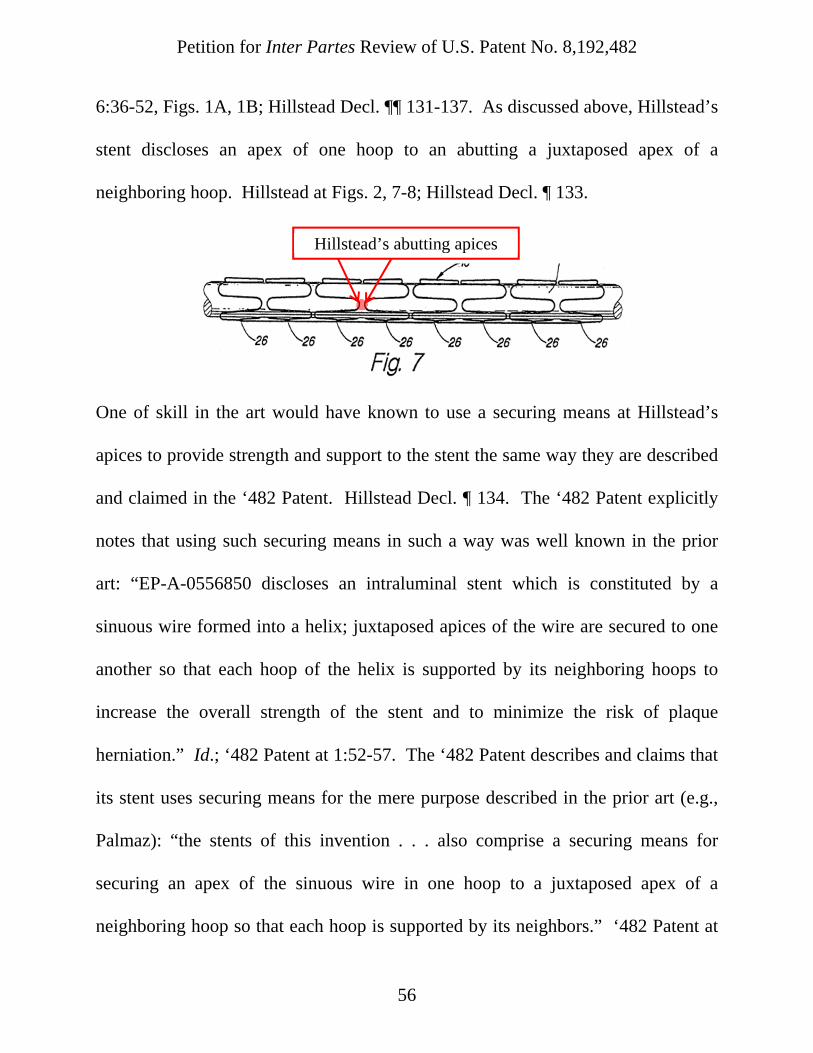
Petition for Inter Partes Review of U.S. Patent No. 8,192,482
56
6:36-52, Figs. 1A, 1B; Hillstead Decl. ¶¶ 131-137. As discussed above, Hillstead’s
stent discloses an apex of one hoop to an abutting a juxtaposed apex of a
neighboring hoop. Hillstead at Figs. 2, 7-8; Hillstead Decl. ¶ 133.
One of skill in the art would have known to use a securing means at Hillstead’s
apices to provide strength and support to the stent the same way they are described
and claimed in the ‘482 Patent. Hillstead Decl. ¶ 134. The ‘482 Patent explicitly
notes that using such securing means in such a way was well known in the prior
art: “EP-A-0556850 discloses an intraluminal stent which is constituted by a
sinuous wire formed into a helix; juxtaposed apices of the wire are secured to one
another so that each hoop of the helix is supported by its neighboring hoops to
increase the overall strength of the stent and to minimize the risk of plaque
herniation.” Id.; ‘482 Patent at 1:52-57. The ‘482 Patent describes and claims that
its stent uses securing means for the mere purpose described in the prior art (e.g.,
Palmaz): “the stents of this invention . . . also comprise a securing means for
securing an apex of the sinuous wire in one hoop to a juxtaposed apex of a
neighboring hoop so that each hoop is supported by its neighbors.” ‘482 Patent at
Hillstead’s abutting apices

Petition for Inter Partes Review of U.S. Patent No. 8,192,482
57
4:21-25; Hillstead Decl. ¶ 135. Further, Hillstead explicitly discloses that sutures
are a suitable securing means. Hillstead at 3:31-36; Hillstead Decl. ¶ 136. Sutures
are one of the securing means described and claimed in the ‘482 Patent. ‘482
Patent at 4:25-29; Hillstead Decl. ¶ 136. Accordingly, the modification of
Hillstead’s stent to include sutures to secure “an apex of one hoop to an abutting a
juxtaposed apex of a neighboring hoop” would have been a simple modification in
view of Palmaz and the well known prior art that would achieve a predictable
result, i.e., increased support and stability of the stent. Hillstead Decl. ¶ 136.
H. Ground 8: Claims 1-9, 12-13, 21-22, and 30 Are Obvious Over Hillstead In View Of Palmaz and Ryan
To the extent claims 1-9, 12-13, 21-22, and 30 are not anticipated by
Hillstead, they are rendered obvious by Hillstead in view of Palmaz and Ryan.
Hillstead Decl. ¶¶ 138-144. As discussed above, it would have been obvious to
one of skill in the art to combine certain disclosures of Palmaz with Hillstead or to
make simple substitutions or modifications of the Hillstead stent based on Palmaz.
Id. at ¶ 139. It would have also been obvious for one of skill in the art at the time
to make further simple modifications to the Hillstead/Palmaz stent based on the
disclosures of Ryan related to the orientation of stent segments and inclusion of a
fabric to connect stent segments. Id.
Specifically, the combined Hillstead/Palmaz/Ryan prosthesis would include
the non-helical hoop structure disclosed by Hillstead where the apices of abutting

Petition for Inter Partes Review of U.S. Patent No. 8,192,482
58
hoops would be secured as disclosed by Palmaz. Id. at ¶ 140. Further the
prosthesis could be bifurcated with a body/trunk segment and two leg segments
connected to the trunk segment by fabric as disclosed by Ryan. Id. One of skill in
the art at the time would have recognized the Hillstead/Palmaz stent structure as a
suitable design for a bifurcated prosthesis, particularly in view of Ryan’s
suggestion that a bifurcated structure employ a sturdy, flexible stent structure and
Hillstead’s goal of a “sturdy, yet flexible” stent. Hillstead at 2:24; Ryan at 5:34-
37; Hillstead Decl. ¶ 140.
Demonstrative of a variation of the obvious
Hillstead/Palmaz/Ryan prosthesis (“H/P/R Figure”)
Stent segments of Hillstead
Securing means of Hillstead/Palmaz
Bifurcated fabric graft connector with trunk
and legs of Ryan

Petition for Inter Partes Review of U.S. Patent No. 8,192,482
59
As shown above, Hillstead and Ryan each, individually disclose and claims
1-3, 5-6, 12-13, 21 and 30 and the combination of Hillstead and Palmaz discloses
claims 1-3, 5-6, 12-13, 21 and 30. Hillstead Decl. ¶¶ 51-82, 112-137. For the
reasons stated above, the Hillstead/Palmaz/Ryan combination would similarly
disclose every element of claims 1-3, 5-6, 12-13, 21 and 30. Id. at ¶¶ 138-141.
The Hillstead/Palmaz/Ryan combination additionally discloses the dependent
claim limitations of claims 4, 7-9 and 22. Id. at ¶¶ 142-144.
Claims 4 and 22: The Hillstead/Palmaz/Ryan combination discloses “a stent
as recited in claim 3 wherein said axially aligned segments are connected to one
another by a tubular fabric element” and “an endoluminal stent as claimed in claim
1 wherein said stent is at least partially covered in fabric.” Hillstead Decl. ¶ 142.
As shown in the H/P/R figure above, it would have been obvious to attach a
Hillstead-like trunk segment to Hillstead-like leg segments using a tubular fabric
element as disclosed in Ryan. Id.
Claim 7: The Hillstead/Palmaz/Ryan (“H/P/R”) combination discloses a
“stent as recited in claim 2 wherein adjacent hoops are of a different diameter.”
Hillstead Decl. ¶ 143. As shown in the H/P/R figure above, it would have been
obvious to use a stent with hoops having a smaller diameter in the leg segments
than the diameter of the trunk segment. Id. Additionally, as shown above, the

Petition for Inter Partes Review of U.S. Patent No. 8,192,482
60
proximal most leg segments are adjacent to the distal most trunk segment, and
thus, adjacent hoops would have different diameters. Id.
Claims 8 and 9: The Hillstead/Palmaz/Ryan combination discloses a “stent
as recited in claim 2 wherein a first additional segment is axially parallel to, but
non-common co-axial with, said stent segment” and a “stent as recited in claim 8
further comprising a second additional segment axially parallel to said stent
segment, but non-co-axial with either said stent segment or said first additional
stent segment.” Hillstead Decl. ¶ 144. As shown above regarding the disclosure of
Ryan alone, the bifurcation of a stent creates multiple longitudinal axes through the
legs that are parallel to, but non-common co-axial with the longitudinal axis of the
trunk. Ryan at Fig. 12; Hillstead Decl. ¶ 144.
X. CONCLUSION
Petitioner requests cancellation of claims 1-9, 12-13, 21-22, and 30 for the
reasons herein.
Respectfully submitted by K&L Gates LLP,
By: /Sanjay K. Murthy/ Reg. No. 45,976 Sanjay K. Murthy Customer No. 24573 Date: August 12, 2015 K&L Gates LLP e-mail: [email protected] telephone number: (312) 807-4416 fax number: (312) 827-8138 70 W. Madison Street, Suite 3100 Chicago, IL 60602

Certification of Service Under 37 C.F.R. § 42.6(e)(4)
A copy of this Petition for Inter Partes Review and supporting materials
have been served to counsel for the Patent Owner at the following electronic mail
address, pursuant to an agreement between the parties, on this 12th day of August,
2015:
Kevin G. Waddick - [email protected] Jeffery L. Cameron - [email protected] Edward J. Brooks III - [email protected]
By: /Sanjay K. Murthy/ Reg. No. 45,976 Sanjay K. Murthy Customer No. 24573 Date: August 12, 2015 K&L Gates LLP e-mail: [email protected] telephone number: (312) 807-4416 fax number: (312) 827-8138 70 W. Madison Street, Suite 3100 Chicago, IL 60602